WO2021220571A1 - Automatic analysis device - Google Patents
Automatic analysis device Download PDFInfo
- Publication number
- WO2021220571A1 WO2021220571A1 PCT/JP2021/003959 JP2021003959W WO2021220571A1 WO 2021220571 A1 WO2021220571 A1 WO 2021220571A1 JP 2021003959 W JP2021003959 W JP 2021003959W WO 2021220571 A1 WO2021220571 A1 WO 2021220571A1
- Authority
- WO
- WIPO (PCT)
- Prior art keywords
- reagent
- reagent bottle
- nozzle
- stopper
- automatic analyzer
- Prior art date
Links
- 238000004458 analytical method Methods 0.000 title claims abstract description 16
- 239000003153 chemical reaction reagent Substances 0.000 claims abstract description 365
- 238000009434 installation Methods 0.000 claims abstract description 46
- 230000001174 ascending effect Effects 0.000 claims description 3
- 230000007246 mechanism Effects 0.000 description 45
- 239000000523 sample Substances 0.000 description 34
- 238000001514 detection method Methods 0.000 description 31
- 239000000243 solution Substances 0.000 description 23
- 238000004140 cleaning Methods 0.000 description 19
- 239000007788 liquid Substances 0.000 description 18
- 238000000034 method Methods 0.000 description 15
- 238000007885 magnetic separation Methods 0.000 description 14
- 230000008569 process Effects 0.000 description 13
- 238000012546 transfer Methods 0.000 description 12
- 238000010586 diagram Methods 0.000 description 10
- 230000032258 transport Effects 0.000 description 7
- 239000006249 magnetic particle Substances 0.000 description 6
- 238000005259 measurement Methods 0.000 description 5
- 238000000926 separation method Methods 0.000 description 5
- 238000003756 stirring Methods 0.000 description 5
- 239000000126 substance Substances 0.000 description 5
- 238000003780 insertion Methods 0.000 description 4
- 230000037431 insertion Effects 0.000 description 4
- 230000007723 transport mechanism Effects 0.000 description 4
- 238000003556 assay Methods 0.000 description 3
- 239000000463 material Substances 0.000 description 3
- 239000000427 antigen Substances 0.000 description 2
- 102000036639 antigens Human genes 0.000 description 2
- 108091007433 antigens Proteins 0.000 description 2
- 239000008280 blood Substances 0.000 description 2
- 210000004369 blood Anatomy 0.000 description 2
- 238000007599 discharging Methods 0.000 description 2
- 230000000694 effects Effects 0.000 description 2
- 238000003018 immunoassay Methods 0.000 description 2
- 239000003960 organic solvent Substances 0.000 description 2
- 230000002265 prevention Effects 0.000 description 2
- 238000012545 processing Methods 0.000 description 2
- 210000002700 urine Anatomy 0.000 description 2
- 239000007864 aqueous solution Substances 0.000 description 1
- 239000011324 bead Substances 0.000 description 1
- 239000012472 biological sample Substances 0.000 description 1
- 230000004397 blinking Effects 0.000 description 1
- 238000004590 computer program Methods 0.000 description 1
- 230000006866 deterioration Effects 0.000 description 1
- 230000002489 hematologic effect Effects 0.000 description 1
- 230000010365 information processing Effects 0.000 description 1
- 150000002632 lipids Chemical class 0.000 description 1
- 239000004973 liquid crystal related substance Substances 0.000 description 1
- 238000012986 modification Methods 0.000 description 1
- 230000004048 modification Effects 0.000 description 1
- 102000004169 proteins and genes Human genes 0.000 description 1
- 108090000623 proteins and genes Proteins 0.000 description 1
- 238000003908 quality control method Methods 0.000 description 1
- 230000009257 reactivity Effects 0.000 description 1
- 230000000630 rising effect Effects 0.000 description 1
- 150000003839 salts Chemical class 0.000 description 1
- 239000004065 semiconductor Substances 0.000 description 1
- 238000012360 testing method Methods 0.000 description 1
- 238000005406 washing Methods 0.000 description 1
Images


Classifications
-
- G—PHYSICS
- G01—MEASURING; TESTING
- G01N—INVESTIGATING OR ANALYSING MATERIALS BY DETERMINING THEIR CHEMICAL OR PHYSICAL PROPERTIES
- G01N35/00—Automatic analysis not limited to methods or materials provided for in any single one of groups G01N1/00 - G01N33/00; Handling materials therefor
- G01N35/00584—Control arrangements for automatic analysers
- G01N35/00722—Communications; Identification
- G01N35/00732—Identification of carriers, materials or components in automatic analysers
-
- G—PHYSICS
- G01—MEASURING; TESTING
- G01N—INVESTIGATING OR ANALYSING MATERIALS BY DETERMINING THEIR CHEMICAL OR PHYSICAL PROPERTIES
- G01N35/00—Automatic analysis not limited to methods or materials provided for in any single one of groups G01N1/00 - G01N33/00; Handling materials therefor
- G01N35/02—Automatic analysis not limited to methods or materials provided for in any single one of groups G01N1/00 - G01N33/00; Handling materials therefor using a plurality of sample containers moved by a conveyor system past one or more treatment or analysis stations
- G01N35/026—Automatic analysis not limited to methods or materials provided for in any single one of groups G01N1/00 - G01N33/00; Handling materials therefor using a plurality of sample containers moved by a conveyor system past one or more treatment or analysis stations having blocks or racks of reaction cells or cuvettes
-
- G—PHYSICS
- G01—MEASURING; TESTING
- G01N—INVESTIGATING OR ANALYSING MATERIALS BY DETERMINING THEIR CHEMICAL OR PHYSICAL PROPERTIES
- G01N35/00—Automatic analysis not limited to methods or materials provided for in any single one of groups G01N1/00 - G01N33/00; Handling materials therefor
- G01N35/10—Devices for transferring samples or any liquids to, in, or from, the analysis apparatus, e.g. suction devices, injection devices
- G01N35/1002—Reagent dispensers
-
- G—PHYSICS
- G01—MEASURING; TESTING
- G01N—INVESTIGATING OR ANALYSING MATERIALS BY DETERMINING THEIR CHEMICAL OR PHYSICAL PROPERTIES
- G01N35/00—Automatic analysis not limited to methods or materials provided for in any single one of groups G01N1/00 - G01N33/00; Handling materials therefor
- G01N35/10—Devices for transferring samples or any liquids to, in, or from, the analysis apparatus, e.g. suction devices, injection devices
- G01N35/1009—Characterised by arrangements for controlling the aspiration or dispense of liquids
-
- G—PHYSICS
- G01—MEASURING; TESTING
- G01N—INVESTIGATING OR ANALYSING MATERIALS BY DETERMINING THEIR CHEMICAL OR PHYSICAL PROPERTIES
- G01N35/00—Automatic analysis not limited to methods or materials provided for in any single one of groups G01N1/00 - G01N33/00; Handling materials therefor
- G01N35/00584—Control arrangements for automatic analysers
- G01N35/00722—Communications; Identification
- G01N35/00732—Identification of carriers, materials or components in automatic analysers
- G01N2035/00742—Type of codes
-
- G—PHYSICS
- G01—MEASURING; TESTING
- G01N—INVESTIGATING OR ANALYSING MATERIALS BY DETERMINING THEIR CHEMICAL OR PHYSICAL PROPERTIES
- G01N35/00—Automatic analysis not limited to methods or materials provided for in any single one of groups G01N1/00 - G01N33/00; Handling materials therefor
- G01N35/00584—Control arrangements for automatic analysers
- G01N35/00722—Communications; Identification
- G01N35/00732—Identification of carriers, materials or components in automatic analysers
- G01N2035/00792—Type of components bearing the codes, other than sample carriers
- G01N2035/00811—Type of components bearing the codes, other than sample carriers consumable or exchangeable components other than sample carriers, e.g. detectors, flow cells
-
- G—PHYSICS
- G01—MEASURING; TESTING
- G01N—INVESTIGATING OR ANALYSING MATERIALS BY DETERMINING THEIR CHEMICAL OR PHYSICAL PROPERTIES
- G01N35/00—Automatic analysis not limited to methods or materials provided for in any single one of groups G01N1/00 - G01N33/00; Handling materials therefor
- G01N35/02—Automatic analysis not limited to methods or materials provided for in any single one of groups G01N1/00 - G01N33/00; Handling materials therefor using a plurality of sample containers moved by a conveyor system past one or more treatment or analysis stations
- G01N35/04—Details of the conveyor system
- G01N2035/0401—Sample carriers, cuvettes or reaction vessels
- G01N2035/0403—Sample carriers with closing or sealing means
- G01N2035/0405—Sample carriers with closing or sealing means manipulating closing or opening means, e.g. stoppers, screw caps, lids or covers
-
- G—PHYSICS
- G01—MEASURING; TESTING
- G01N—INVESTIGATING OR ANALYSING MATERIALS BY DETERMINING THEIR CHEMICAL OR PHYSICAL PROPERTIES
- G01N35/00—Automatic analysis not limited to methods or materials provided for in any single one of groups G01N1/00 - G01N33/00; Handling materials therefor
- G01N35/02—Automatic analysis not limited to methods or materials provided for in any single one of groups G01N1/00 - G01N33/00; Handling materials therefor using a plurality of sample containers moved by a conveyor system past one or more treatment or analysis stations
- G01N35/04—Details of the conveyor system
- G01N2035/0401—Sample carriers, cuvettes or reaction vessels
- G01N2035/0406—Individual bottles or tubes
Definitions
- the present invention relates to an automatic analyzer that analyzes the concentration of a predetermined component in a biological sample (hereinafter referred to as a sample) such as blood or urine using a reagent.
- a biological sample hereinafter referred to as blood or urine
- Patent Document 1 describes a container installation unit on which a reagent bottle can be installed and an opening / closing unit provided in the reagent bottle installation unit.
- a possible cover, a solenoid that locks the cover in the open position, and an information processing unit that controls locking and unlocking of the cover in the open position by the solenoid are provided, and the cover is locked in the open position when exchanging reagents. Is described.
- An automatic analyzer that analyzes a sample using a reagent installed in the device is known.
- reagents used in the automatic analyzer: reagents that are individually prepared for each measurement target item (hereinafter, assay reagents) and reagents that are commonly used for various measurement target items (hereinafter, system reagents). Reagents are often used.
- a container installation portion in which a reagent bottle containing a reagent used for analysis can be installed and a cover for opening or closing the container installation portion are installed, and the cover portion. Describes how to lock or unlock.
- this cover and the nozzle part inserted into the reagent are linked.
- the reagent type is recognized, and if it is recognized as the correct reagent type, the cover and nozzle are allowed to descend, and if it is not recognized as the correct reagent type, the nozzle is prohibited from descending to prevent erroneous installation.
- the cover and nozzle are prohibited from rising except when the reagent should be replaced, thereby preventing the user from accidentally removing the reagent.
- the present invention has been made to solve the above problems, and provides an automatic analyzer that realizes prevention of misplacement of reagent types and prevention of reagent removal at incorrect timings with less space and components.
- the present invention includes a plurality of means for solving the above problems.
- the reagent suction nozzle of the nozzle unit is arranged on the moving path of the reagent suction nozzle, and the reagent suction nozzle is a reagent. It is characterized by having a stopper that prevents it from being inserted into the bottle.
- FIG. 5 it is a figure which shows the whole structure of the automatic analyzer in embodiment of this invention. It is a figure which shows an example of the outline of the reagent bottle which contains the system reagent used in the automatic analyzer of this invention. It is a figure which shows the schematic structure of the reagent bottle installation part and the nozzle unit of the automatic analyzer of this invention. It is a figure which shows the schematic structure of the reagent bottle installation part and the nozzle unit of the automatic analyzer of this invention. It is a flowchart at the time of setting the reagent bottle in the automatic analyzer of this invention. In FIG. 5, it is a figure which shows the positional relationship between the reagent bottle and the stopper at the time of step S4. In FIG.
- FIG. 5 it is a figure which shows the positional relationship between the reagent bottle and the stopper at the time of step S6.
- FIG. 5 it is a figure which shows the positional relationship between the reagent bottle and the stopper at the time of step S7.
- FIG. 5 is a diagram showing a positional relationship between the reagent bottle and the stopper after step S8. It is a flowchart at the time of removing a reagent bottle by the automatic analyzer of this invention.
- FIG. 10 it is a figure which shows the positional relationship between the reagent bottle and the stopper at the time of step S11.
- FIG. 10 it is a figure which shows the positional relationship between the reagent bottle and the stopper at the time of step S12.
- an immunoassay device will be described as an example.
- the automatic analyzer to which the reagent bottle installation configuration disclosed in the present invention is applied is not limited to the immunoassay device, and all automatic analyzers using system reagents, such as biochemical automatic analyzer, hematological test device, and liquid. It can be applied to a chromatograph mass spectrometer or the like.
- FIG. 1 is a diagram showing an overall configuration of an immunoautomatic analyzer of this embodiment.
- the immunoautomatic analyzer 1 shown in FIG. 1 is a device for reacting a sample and a reagent and measuring the reacted reaction solution, and is a transfer line 100, a sample dispensing mechanism 103, an incubator 109, a magazine 108, and a transfer.
- the transport line 100 is a line for transporting a rack 100A on which a plurality of sample containers 100B containing a sample can be placed to a sample dispensing position or the like.
- the sample dispensing mechanism 103 is a nozzle for sucking the sample contained in the sample container 100B and discharging it to the reaction container 106 on the incubator 109.
- the incubator 109 is a disk for carrying out the reaction between the sample and the reagent at a constant temperature, and by keeping the temperature at a predetermined temperature by a heater (not shown), the reaction between the sample and the reagent is promoted.
- a plurality of reaction vessels 106 are held in the incubator 109, and serve as a place for mixing and reacting a sample and a reagent.
- the magazine 108 reacts by inserting a disposable dispensing chip 107 that is attached to the tip of the sample dispensing mechanism 103 and used when dispensing and dispensing the sample, and the sample and the reagent separated by the sample dispensing mechanism 103.
- the reaction vessel 106 for carrying out the above is stored.
- the transport mechanism 113 transports the unused reaction vessel 106 held in the magazine 108 to the incubator 109, and the used reaction vessel 106 to the reaction vessel disposal unit 110, and the unused reaction vessel 106 held in the magazine 108.
- the dispensing tip 107 is transported to the dispensing tip mounting position 111, and the used dispensing tip 107 is transported to the dispensing tip disposal site 112.
- the reagent disk 102 is a disk for storing the reagent bottle 101 containing the assay reagent, and is kept cold in order to suppress deterioration of the assay reagent.
- the reagent dispensing mechanism 104 is a nozzle for sucking the reagent stored in the reagent bottle 101 in the reagent disk 102 and discharging it to the reaction vessel 106.
- the magnetic particle stirring mechanism 105 stirs the magnetic particle solution among the reagents in the reagent disk 102.
- the BF separation transfer mechanism 115 transports the reaction vessel 106 into which the magnetic particle solution is dispensed from the incubator 109 to the magnetic separation section 114.
- the magnetic separation unit 114 performs a magnetic separation process on the reaction vessel 106 into which the magnetic particle solution is dispensed.
- the reaction solution suction mechanism 116 sucks the reaction solution from the reaction vessel 106 conveyed to the magnetic separation unit 114.
- the cleaning liquid A discharge mechanism 117 discharges the cleaning liquid A to the reaction vessel 106 conveyed to the magnetic separation unit 114.
- the cleaning liquid B discharge mechanism 118 discharges the cleaning liquid B to the reaction vessel 106 conveyed to the magnetic separation unit 114.
- the detection unit transport mechanism 121 transports the reaction vessel 106 from the incubator 109 to the detection unit 120, or from the detection unit 120 to the incubator 109.
- the detection solution discharge mechanism 119 discharges the reagent for detection to the reaction vessel 106 transported to the detection unit 120 by the detection unit transfer mechanism 121.
- the detection unit 120 detects the substance to be measured in the reaction solution in the reaction vessel 106 in which the detection reagent is discharged by the detection solution discharge mechanism 119.
- the cleaning step performed in the magnetic separation unit 114 is carried out in order to remove the substance derived from the sample remaining in the reaction solution.
- cleaning is performed using two types of cleaning solutions in sequence.
- An aqueous solution is used as the cleaning liquid A, and mainly removes coexisting substances such as inorganic salts.
- a solution containing an organic solvent is used as the cleaning liquid B, and mainly removes coexisting substances such as lipids and proteins.
- the detection reagent discharged from the detection solution discharge mechanism 119 is used to adjust the pH and the like in order to obtain a liquid property suitable for detection after the washing step.
- the cleaning solutions A and B and the detection solution are collectively called system reagents.
- the control unit 131 is a computer that controls various operations of the above-mentioned members and performs arithmetic processing for obtaining the concentration of a predetermined component in the sample from the detection result performed by the detection unit 120, and is one or a plurality of computers. It is composed of the processor, CPU, etc.
- the control unit 131 controls the operation of each device by various programs. This program is stored in a recording device 132 or the like, is read by a CPU, and is executed.
- control processing executed by the control unit 131 may be integrated into one program, may be divided into a plurality of programs, or may be a combination thereof. Further, a part or all of the program may be realized by dedicated hardware or may be modularized.
- the recording device 132 is a recording medium for recording data related to a sample input into the immunoautomatic analyzer 1 and analysis results, and is composed of a semiconductor memory such as a flash memory, a magnetic disk such as an HDD, or the like.
- the recording device 132 also records various computer programs and the like for controlling the operation of each device in the immune automatic analyzer 1 and executing various display processes described later.
- the display device 133 is a display device such as a liquid crystal display that displays information related to the analysis result and the progress of the analysis.
- the input device 134 is composed of a keyboard and a mouse for inputting data.
- the transport mechanism 113 transports the unused reaction vessel 106 and the dispensing tip 107 to the incubator 109 and the dispensing tip mounting position 111.
- the reagent dispensing mechanism 104 accesses the reagent disk 102, the reagent stored in the reagent bottle 101 is dispensed into the reaction vessel 106 on the incubator 109.
- the reaction referred to here means, for example, binding a sample to a luminescent labeled substance by an antigen-antibody reaction using a luminescent labeled antibody that reacts only with a specific antigen of the sample as a reagent.
- the used dispensing tip 107 is conveyed to the dispensing tip disposal site 112 by the conveying mechanism 113 and discarded.
- reaction vessel 106 placed in the incubator 109 for a predetermined time is transported to the magnetic separation unit 114 by the BF separation transfer mechanism 115.
- the sample is magnetically separated, then an unnecessary solution is discharged from the reaction solution suction mechanism 116, and a system reagent called a cleaning liquid is discharged from the cleaning liquid A discharge mechanism 117 and the cleaning liquid B discharge mechanism 118. Will be done.
- reaction vessel 106 is transferred from the magnetic separation unit 114 to the incubator 109 again by the BF separation transfer mechanism 115.
- the reaction vessel 106 that has been placed in the incubator 109 for a predetermined time is conveyed to the detection unit 120 by the detection unit transfer mechanism 121, and the detection reagent is discharged by the detection solution discharge mechanism 119. After that, the detection unit 120 detects the signal from the reaction solution, and the detection result is output to the control unit 131.
- the control unit 131 obtains the concentration of a predetermined component in the sample, and the result is displayed on the display device 133 and notified to the user, and is recorded on the recording device 132.
- reaction vessel 106 is conveyed to the reaction vessel disposal unit 110 by the detection unit transfer mechanism 121 and the transfer mechanism 113 and discarded.
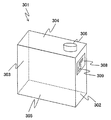
- FIG. 2 is a diagram showing an outline of an outline of a reagent bottle containing a system reagent used in an automatic analyzer as shown in FIG.
- the reagent bottle 301 shown in FIG. 2 is a plastic container having a shape having a long depth with respect to the width.
- each surface shown in FIG. 2 will be described as a front surface 302, a side surface 303, an upper surface 304, and a bottom surface 305 in the insertion direction.
- a columnar screw lid 306 is provided on the upper surface 304 of the reagent bottle 301 at a position where the reagent suction nozzle 400 of the nozzle unit 210 of the reagent bottle installation portion 200, which will be described later, can be inserted.
- a label 308 on which the type of reagent, expiration date, etc. are described is affixed to the front 302 in the insertion direction of the reagent bottle 301.
- An RFID tag 309 is attached to the label 308.
- the RFID tag 309 records information about the system reagent such as reagent type, lot number, expiration date, whether it has been used, and the number of remaining uses.
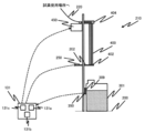
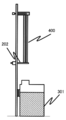
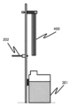
- FIGS. 3 and 4 are diagrams showing a schematic configuration of the reagent bottle installation unit 200 and the nozzle unit 210.
- a plurality of reagent bottle installation portions 200 as shown in FIG. 3 are installed on the back side of the front cover.
- the reagent bottle installation unit 200 is a portion for installing the reagent bottle 301 containing the reagent used for analysis, and is a stopper 202, a stopper drive unit 250, a nozzle unit 210, and an RFID. It has a reader 350. Further, among the control units 131, as a part related to the reagent bottle installation unit 200, there are a reagent determination unit 131a, a stopper drive control unit 131b, and a nozzle drive control unit 131c in the control unit 131.
- the nozzle unit 210 is a unit for joining the supply flow path 220 that connects the place where the reagent is used and the inside of the reagent bottle 301 installed in the reagent bottle installation unit 200 to the reagent bottle 301, and sucks the reagent. It is composed of a nozzle 400 and a nozzle drive unit 450.
- the reagent suction nozzle 400 is a device for joining the supply flow path 220 connecting the location where the reagent is used and the reagent bottle 301 installed in the reagent bottle installation unit 200 to the reagent bottle 301, and is a nozzle drive control unit.
- the nozzle drive unit 450 of a motor or the like under the control of 131c, the reagent suction nozzle 400 is inserted into the reagent in the reagent bottle 301 installed in the reagent bottle installation unit 200, or is removed from the reagent bottle 301. It is configured.
- the reagent suction nozzle 400 is connected to a liquid drive device such as a supply flow path 220 and a syringe (not shown), and the reagent can be supplied from the reagent bottle 301 to a place of use on the device.
- a liquid drive device such as a supply flow path 220 and a syringe (not shown)
- the reagent can be supplied from the reagent bottle 301 to a place of use on the device.
- the stopper 202 is a space between the lower end 402 of the reagent suction nozzle 400 and the reagent bottle 301 as a position on the movement path of the reagent suction nozzle 400 that prevents the reagent suction nozzle 400 from being inserted into the reagent bottle 301. Is located in.
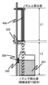
- the stopper 202 is shown in FIGS. 3 and 3 so as to prevent the reagent in the reagent suction nozzle 400 from adhering to the hands of an operator performing the replacement work by any chance when the reagent bottle 301 is replaced.
- the lower end 402 of the reagent suction nozzle 400 and the upper surface side of the stopper 202 are arranged at positions where they come into contact with each other.
- the stopper 202 is arranged at a position where the length L1 from the upper end 404 to the lower end 402 of the reagent suction nozzle 400 and the moving distance L2 of the reagent suction nozzle 400 are equal to each other.
- L1 may be shorter than L2.
- the reagent suction nozzle 400 is joined to the reagent bottle 301, and when it is determined that the reagent is being used, the reagent suction nozzle 400 is arranged at a position where it interferes with the removal even if it is attempted to be removed. There is.
- the material of the stopper 202 is not particularly limited, but it is preferably a material having poor reactivity with the reagent. Further, the rigidity and the like are not particularly limited, but when the lower end 402 of the reagent suction nozzle 400 and the upper surface side of the stopper 202 come into contact with each other, the flexibility is intended to surely prevent the reagent suction nozzle 400 from being deformed. It may be desirable to use a material that has.
- the shape is not particularly limited, and various shapes such as a flat plate can be used.
- the stopper 202 protrudes from the side surface of the reagent bottle installation unit 200 by driving the stopper drive unit 250 such as a motor under the control of the stopper drive control unit 131b, or retracts to the side surface to suck the reagent into the reagent bottle 301. It is configured to prevent the nozzle 400 from being set or removed from the reagent bottle 301.
- the reagent determination unit 131a determines whether or not the reagent bottle 301 installed in the reagent bottle installation unit 200 is appropriate from the reagent information read by the RFID reader 350, and determines the determination result by the stopper drive control unit 131b or the nozzle. Output to the drive control unit 131c.
- stopper drive control unit 131b fixes the stopper 202 except for the timing of replacing the reagent bottle 301, and drives and controls the stopper drive unit 250 so as to prevent the reagent suction nozzle 400 from moving.
- the stopper drive control unit 131b drives the stopper 202 to suck the reagent into the reagent bottle 301 when it is determined from the reagent information that the reagent bottle 301 installed in the reagent bottle installation unit 200 is correct. It is desirable not to interfere with the access of the nozzle 400. Further, when it is not determined that the reagent bottle 301 is correct, it is desirable to prevent the reagent suction nozzle 400 from moving without driving the stopper 202.
- the nozzle drive control unit 131c is a portion that controls the ascending and descending operations of the reagent suction nozzle 400, and the nozzle drive unit 450 is used to fix the reagent suction nozzle 400 except for the timing of replacing the reagent bottle 301. It is desirable to drive and control.
- the nozzle drive control unit 131c drives the reagent suction nozzle 400 when it is determined from the reagent information that the reagent bottle 301 installed in the reagent bottle installation unit 200 is correct, and the reagent bottle 301 is correct. If it is not determined, it is desirable to keep the reagent suction nozzle 400 fixed without driving it.
- the RFID reader 350 is a device that reads the reagent information recorded on the RFID tag 309 attached to the label 308 of the reagent bottle 301, and the front side 302 of the reagent bottle installation unit 200 in the insertion direction of the reagent bottle 301 is inserted.
- the RFID tag 309 is installed in a readable position at the stopped position.
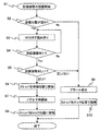
- FIG. 5 is a flowchart at the time of installing the reagent bottle.
- FIG. 6 is a diagram showing the positional relationship between the reagent bottle and the stopper at the time of step S4 in FIG.
- FIG. 7 is a diagram showing the positional relationship between the reagent bottle and the stopper at step S6 in FIG.
- FIG. 8 is a diagram showing the positional relationship between the reagent bottle and the stopper at the time of step S7 in FIG.
- FIG. 9 is a diagram showing the positional relationship between the reagent bottle and the stopper after step S8 in FIG.
- step S1 When starting the installation of the reagent bottle 301 (FIG. 5, step S1), first, the control unit 131 is set by the reagent bottle installation unit 200 in which the user intends to install the reagent bottle 301 based on the information from the RFID reader 350. It is determined whether or not it is empty (step S2). When it is determined that the reagent bottle setting unit 200 is empty, the process proceeds to step S3. On the other hand, when it is determined that the reagent bottle is not empty, it means that the reagent bottle 301 already in use exists, and the user cannot install the reagent bottle 301. At this time, the process proceeds to step S9.
- the reagent bottle 301 to be installed by the user is placed in the reagent bottle installation unit 200.
- the stopper drive control unit 131b fixes the stopper 202 at the locked position
- the nozzle drive unit 450 fixes the reagent suction nozzle 400 at the raised position.
- the stopper 202 is maintained between the lower end 402 of the reagent suction nozzle 400 and the reagent bottle 301, and the reagent suction nozzle 400 cannot be lowered until the correctness of the installed reagent is confirmed. It is possible to prevent the reagent bottle 301 from being installed and to prevent dripping from the lower end 402 of the reagent suction nozzle 400.
- the information on the RFID tag 309 can be read by the RFID reader 350, so that the RFID reader 350 attempts to read the RFID tag 309 at regular intervals (step). S3).
- control unit 131 determines whether or not the information of the RFID tag 309 can be read by the RFID reader 350, that is, whether or not the reagent bottle 301 is arranged in the reagent bottle installation unit 200 (step S4).
- the process proceeds to step S5.
- the process is returned to step S3 until it is installed, and it waits for it to be installed.
- steps S2 and S3 are not limited to the case where the RFID tag 309 is read by the RFID reader 350, and the determination can be made based on the information from the reagent bottle detection sensor.
- the reagent determination unit 131a determines whether or not the reagent bottle 301 installed by the user is correct (step). S5).
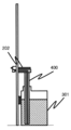
- step S5 When it is determined in step S5 that the reagent bottle 301 installed by the user may be installed, the stopper drive control unit 131b moves the stopper 202 to the standby position and fixes it as shown in FIG. 7 (step S6). ).
- the nozzle drive control unit 131c starts lowering the reagent suction nozzle 400 (step S7), and stops lowering when connected to the reagent bottle 301 as shown in FIG. In this state, the reagent can be sucked.
- the stopper drive control unit 131b moves the stopper 202 to the lock position and fixes it as shown in FIG. 9 (step S8).
- the stopper drive control unit 131b moves the stopper 202 to the lock position and fixes it as shown in FIG. 9 (step S8).
- step S5 it is determined that the reagent should not be installed if the reagent type is different, the expiration date has expired, or the reagent bottle 301 has already been used in another device. Is. Further, even if the information read from the RFID tag 309 deviates from the information that should be read originally, it is determined that the information should not be installed. These determinations are made by the reagent determination unit 131a of the control unit 131 based on the information read from the RFID tag 309 by the RFID reader 350. When the reagent determination unit 131a determines that the reagent bottle 301 to be installed by the user should not be installed, the process proceeds to step S9.
- step S2 If it is determined that the reagent bottle 301 that the user is trying to install should not be installed, it is desirable to notify the user. Therefore, when it is determined in step S2 that the reagent bottle installation unit 200 is not empty, or when it is determined in step S5 that the reagent information is incorrect, the reagent determination unit 131a issues an alarm (step S9), and the user Notify to.
- the notification method includes, for example, turning on the indicator lamp, displaying an alarm on the user interface, and the like.
- the indicator lamp is composed of a button or the like with a built-in LED, which is often arranged in the upper part of the reagent bottle installation unit 200 in the reagent bottle installation unit 200. Depending on how this indicator lamp is lit, it is often used to notify the user of the slot in which the reagent bottle that needs to be replaced is located, or to notify the user that an inappropriate reagent has been installed. .. Further, as described above, this indicator lamp also serves as a button, and when the user presses the reagent bottle 301 when the reagent bottle 301 has been installed in the reagent bottle installation unit 200, the apparatus side has completed the installation of the reagent bottle 301. Can be recognized.
- step S10 the stopper drive control unit 131b fixes the stopper 202 in the locked position (step S10), and ends the process. Therefore, the stopper 202 interferes with the reagent suction nozzle 400 and remains prevented from being lowered to the connection position with the reagent bottle 301. This makes it possible to prevent the user from installing the reagent bottle 301 which should not be installed originally.
- the order of steps S9 and S10 may be reversed.
- the user confirms whether or not the reagent bottle 301 to be installed can be installed before the reagent suction nozzle 400 is connected to the reagent bottle 301.
- the reagent suction nozzle 400 When the reagent suction nozzle 400 is lowered to the connection position, the reagent suction nozzle 400 is already in contact with the reagent in the reagent bottle 301. Therefore, even if the user notices that the reagent bottle 301 is mistaken by the notification from the apparatus, the reagent is mixed through the reagent suction nozzle 400 and the supply flow path 220 beyond the reagent suction nozzle 400. Mixing with reagents that should not be installed may affect analytical performance, so complicated additional operations such as cleaning the reagent suction nozzle 400 and the supply flow path 220 are required before replacement with the correct reagent.
- the reagent determination unit 131a also issue an alarm in this case as well.
- FIG. 10 is a flowchart when the reagent bottle is removed.
- FIG. 11 is a diagram showing the positional relationship between the reagent bottle and the stopper at the time of step S11 in FIG.
- FIG. 12 is a diagram showing the positional relationship between the reagent bottle and the stopper at the time of step S12 in FIG.
- the reagent bottle 301 needs to be replaced, if the reagent bottle 301 is empty, if the reagent has expired, or if the user explicitly instructs the device to replace the reagent, the device. However, there are cases where it is determined that the installed reagents cannot be used based on the quality control results. These determinations are made by the reagent determination unit 131a of the control unit 131.
- control unit 131 When it is determined that the replacement is necessary, the control unit 131 notifies the user of the reagent replacement by blinking the indicator lamp or the like, and as shown in FIG. 11, the stopper drive control unit 131b puts the stopper 202 in the standby position. And fix it (step S11).
- the reagent suction nozzle 400 can be raised, so the nozzle driving unit 450 raises the reagent suction nozzle 400, and after completion, stops and fixes the reagent suction nozzle 400.
- the stopper drive control unit 131b moves the stopper 202 to the locked position and fixes it (step S12). This allows the user to pull out the reagent bottle 301. The user can easily recognize whether or not the reagent bottle 301 can be removed by whether or not the reagent suction nozzle 400 is raised and the stopper 202 is located between the lower end 402 and the reagent bottle 301. be able to.
- step S12 If the reagent bottle 301 remains connected to the connection position within a predetermined time after step S12, there is a possibility that the replacement operation of the reagent bottle 301 has been forgotten, and thus the control unit. It is desirable that 131 issues an alarm.
- the automatic analyzer 1 of the present embodiment described above has a stopper 202, which is arranged on the movement path of the reagent suction nozzle 400 of the nozzle unit 210 and prevents the reagent suction nozzle 400 from being inserted into the reagent bottle 301. I have.
- the stopper 202 located between the reagent suction nozzle 400 and the reagent bottle 301 has the two purposes of erroneously installing the reagent bottle 301 and accidentally removing the reagent bottle 301 while using the reagent.
- This can be realized by the configuration and operation of the drive mechanism, and the device configuration can be simplified while saving space as compared with the conventional case.
- the stopper 202 can prevent the liquid from being received and contacting the user. Also plays.
- the configuration is particularly suitable for a place where a container containing an organic solvent is used as a reagent.
- the stopper 202 is arranged at a position where the length L1 from the upper end 404 to the lower end 402 of the reagent suction nozzle 400 and the moving distance L2 of the reagent suction nozzle 400 are equal to each other, when the reagent bottle 301 is replaced, It is possible to prevent the dripping from the lower end 402 of the reagent suction nozzle 400 by any chance, and it is possible to more reliably prevent the reagent from coming into contact with the user.
- a stopper drive control unit 131b for driving and controlling the stopper 202 is further provided, and the stopper drive control unit 131b fixes the stopper 202 except for the timing of replacing the reagent bottle 301 to prevent the reagent suction nozzle 400 from moving. It is possible to surely prevent the wrong reagent bottle 301 from being installed, and more stable sample analysis becomes possible.
- an RFID reader 350 for reading the reagent information recorded on the RFID tag 309 attached to the reagent bottle 301 is further provided, and the stopper drive control unit 131b uses the stopper 202 when it is determined that the reagent bottle 301 is correct.
- the stopper drive control unit 131b uses the stopper 202 when it is determined that the reagent bottle 301 is correct.
- a nozzle drive control unit 131c for controlling the ascending operation and the descending operation of the reagent suction nozzle 400 is further provided, and the nozzle drive control unit 131c fixes the reagent suction nozzle 400 except for the timing of replacing the reagent bottle 301.
- the nozzle drive control unit 131c fixes the reagent suction nozzle 400 except for the timing of replacing the reagent bottle 301.
- an RFID reader 350 for reading the reagent information recorded on the RFID tag 309 attached to the reagent bottle 301 is further provided, and the nozzle drive control unit 131c is a reagent suction nozzle when it is determined that the reagent bottle 301 is correct.
- the reagent installed when the reagent bottle 301 is installed in the reagent bottle installation unit 200 is appropriate. It is possible to automatically determine whether or not there is a reagent and notify the user, and the burden on the user can be further reduced.
- Detection solution discharge mechanism 120 ... Detection unit 121 ... Detection unit Conveying mechanism 131 ... Control unit 131a ... Reagent judgment unit 131b ... Stopper drive control unit (stopper control unit) 131c ... Nozzle drive control unit (nozzle control unit) 132 ... Recording device 133 ... Display device 134 ... Input device 200 ... Reagent bottle installation unit 202 ... Stopper 210 ... Nozzle unit 220 ... Supply flow path 250 ... Stopper drive unit 301 ... Reagent bottle 302 ... Insertion direction Front 303 ... Side side 304 ... Top surface 305 ... Bottom surface 306 ... Lid 308 ... Label 309 ... RFID tag 350 ... RFID reader 400 ... Reagent suction nozzle 402 ... Lower end 404 ... Upper end 450 ... Nozzle drive unit
Landscapes
- Chemical & Material Sciences (AREA)
- Physics & Mathematics (AREA)
- Health & Medical Sciences (AREA)
- Life Sciences & Earth Sciences (AREA)
- Analytical Chemistry (AREA)
- Biochemistry (AREA)
- General Health & Medical Sciences (AREA)
- General Physics & Mathematics (AREA)
- Immunology (AREA)
- Pathology (AREA)
- Chemical Kinetics & Catalysis (AREA)
- Automatic Analysis And Handling Materials Therefor (AREA)
Abstract
An automatic analysis device 1 comprises a reagent bottle installation part 200 where a reagent bottle 301 containing a reagent to be used for analysis is installed, and a nozzle unit 210 for joining, to the reagent bottle 301, a supply flow path 220 connecting the location where the reagent is used to the inside of the reagent bottle 301 installed at the reagent bottle installation part 200, wherein, disposed on a movement path of a reagent suction nozzle 400 of the nozzle unit 210 is a stopper 202 which prevents the reagent suction nozzle 400 from being inserted into the reagent bottle 301. The foregoing provides an automatic analysis device configured to prevent erroneous reagent type placement and the removal of a reagent at the wrong time, with a smaller amount of space and fewer components.
Description
本発明は、試薬を使用して、血液や尿等の生体試料(以下検体と記載)中の所定成分の濃度を分析する自動分析装置に関する。
The present invention relates to an automatic analyzer that analyzes the concentration of a predetermined component in a biological sample (hereinafter referred to as a sample) such as blood or urine using a reagent.
従来に比して試薬ボトルの交換を円滑に行うことが可能な検体分析装置の一例として、特許文献1には、試薬ボトルを設置可能な容器設置部と、試薬ボトル設置部に設けられた開閉可能なカバーと、カバーを開放位置においてロックするソレノイドと、ソレノイドによるカバーの開放位置におけるロック及びロック解除を制御する情報処理ユニットとを備え、試薬交換の際に、カバーを開放位置でロックすることが記載されている。
As an example of a sample analyzer capable of smoothly exchanging reagent bottles as compared with the conventional case, Patent Document 1 describes a container installation unit on which a reagent bottle can be installed and an opening / closing unit provided in the reagent bottle installation unit. A possible cover, a solenoid that locks the cover in the open position, and an information processing unit that controls locking and unlocking of the cover in the open position by the solenoid are provided, and the cover is locked in the open position when exchanging reagents. Is described.
装置内に設置した試薬を用いて検体を分析する自動分析装置が知られている。
An automatic analyzer that analyzes a sample using a reagent installed in the device is known.
自動分析装置で用いられる試薬には、測定対象項目ごとに個別に用意される試薬(以下、アッセイ試薬)と、各種の測定対象項目で共通に使用される試薬(以下、システム試薬)の2種別の試薬を用いることが多い。
There are two types of reagents used in the automatic analyzer: reagents that are individually prepared for each measurement target item (hereinafter, assay reagents) and reagents that are commonly used for various measurement target items (hereinafter, system reagents). Reagents are often used.
このうち、システム試薬は、装置の測定原理や装置の洗浄方法等によって複数搭載することが多い。
Of these, multiple system reagents are often installed depending on the measurement principle of the device and the cleaning method of the device.
ここで、使用中のシステム試薬をユーザが誤って取り外してしまうことが想定される。この場合、装置はシステム試薬が供給されないために測定を継続することができず、停止する。ユーザは再度試薬を設置し、測定をやり直す必要が生じ、分析結果が得られるまでの時間が伸びてしまう。
Here, it is assumed that the user accidentally removes the system reagent in use. In this case, the device will not be able to continue the measurement due to the lack of system reagents and will be shut down. The user has to install the reagent again and repeat the measurement, which increases the time until the analysis result is obtained.
上述した特許文献1に開示された自動分析装置では、分析に用いる試薬が収容された試薬ボトルを設置可能な容器設置部と、容器設置部を開放あるいは閉鎖状態にするカバーを設置し、カバー部をロックする、あるいはロック解除する方法を記載している。
In the automatic analyzer disclosed in Patent Document 1 described above, a container installation portion in which a reagent bottle containing a reagent used for analysis can be installed and a cover for opening or closing the container installation portion are installed, and the cover portion. Describes how to lock or unlock.
さらに、このカバーと試薬に挿入されるノズル部が連動する構成としている。試薬を置いた時に試薬種を認識し、正しい試薬種と認識された場合はカバーおよびノズルが下降することを許可し、正しい試薬種と認識されない場合はノズル下降を禁止し、誤設置を防ぐ。試薬が設置された後は、試薬を交換すべきタイミング以外ではカバーおよびノズルの上昇を禁止することで、ユーザが誤って試薬を取り外すことを防いでいる。
Furthermore, this cover and the nozzle part inserted into the reagent are linked. When the reagent is placed, the reagent type is recognized, and if it is recognized as the correct reagent type, the cover and nozzle are allowed to descend, and if it is not recognized as the correct reagent type, the nozzle is prohibited from descending to prevent erroneous installation. After the reagent is installed, the cover and nozzle are prohibited from rising except when the reagent should be replaced, thereby preventing the user from accidentally removing the reagent.
しかしながら、上記特許文献1に開示された自動分析装置では、試薬を装置に設置する目的では必須ではないカバーを用いる必要がある。このため、試薬設置部が大型化、複雑化するとの課題がある。
However, in the automatic analyzer disclosed in Patent Document 1, it is necessary to use a cover that is not essential for the purpose of installing the reagent in the device. Therefore, there is a problem that the reagent installation part becomes large and complicated.
本発明は上記の課題を解決するためになされたもので、より少ないスペースと構成部品で、試薬種の置き間違え防止と誤ったタイミングでの試薬取り外しの防止を実現する自動分析装置を提供する。
The present invention has been made to solve the above problems, and provides an automatic analyzer that realizes prevention of misplacement of reagent types and prevention of reagent removal at incorrect timings with less space and components.
本発明は、上記課題を解決する手段を複数含んでいるが、その一例を挙げるならば、自動分析装置において、ノズルユニットの試薬吸引ノズルの移動経路上に配置されており、試薬吸引ノズルが試薬ボトル内に挿入されることを妨げるストッパ、を備えていることを特徴とする。
The present invention includes a plurality of means for solving the above problems. For example, in an automatic analyzer, the reagent suction nozzle of the nozzle unit is arranged on the moving path of the reagent suction nozzle, and the reagent suction nozzle is a reagent. It is characterized by having a stopper that prevents it from being inserted into the bottle.
本発明によれば、より少ないスペースと構成部品で、試薬種の置き間違え防止と誤ったタイミングでの試薬取り外しの防止を実現することができる。上記した以外の課題、構成および効果は、以下の実施例の説明により明らかにされる。
According to the present invention, it is possible to prevent the reagent type from being misplaced and the reagent from being removed at the wrong timing with less space and components. Issues, configurations and effects other than those mentioned above will be clarified by the description of the following examples.
本発明の自動分析装置の実施例について図1乃至図12を用いて説明する。
Examples of the automatic analyzer of the present invention will be described with reference to FIGS. 1 to 12.
ここで、以下の実施例では、免疫分析装置を例として説明する。ただし、本発明で開示する試薬ボトル設置の構成が適用される自動分析装置は免疫分析装置に限られず、システム試薬を使用する自動分析装置全般、例えば生化学自動分析装置や血液学検査装置、液体クロマトグラフ質量分析装置等に適用することが可能である。
Here, in the following examples, an immunoassay device will be described as an example. However, the automatic analyzer to which the reagent bottle installation configuration disclosed in the present invention is applied is not limited to the immunoassay device, and all automatic analyzers using system reagents, such as biochemical automatic analyzer, hematological test device, and liquid. It can be applied to a chromatograph mass spectrometer or the like.
最初に、本実施例の免疫自動分析装置の全体構成について図1を用いて説明する。図1は、本実施例の免疫自動分析装置の全体構成を示す図である。
First, the overall configuration of the immune automatic analyzer of this example will be described with reference to FIG. FIG. 1 is a diagram showing an overall configuration of an immunoautomatic analyzer of this embodiment.
図1に示す免疫自動分析装置1は、検体と試薬を反応させ、この反応させた反応液を測定するための装置であり、搬送ライン100、検体分注機構103、インキュベータ109、マガジン108、搬送機構113、試薬ディスク102、試薬分注機構104、磁性粒子撹拌機構105、磁気分離部114、BF分離用搬送機構115、反応溶液吸引機構116、洗浄液A吐出機構117、洗浄液B吐出機構118、検出部搬送機構121、検出用溶液吐出機構119、検出部120、制御部131、記録装置132、表示装置133、入力装置134を備えている。
The immunoautomatic analyzer 1 shown in FIG. 1 is a device for reacting a sample and a reagent and measuring the reacted reaction solution, and is a transfer line 100, a sample dispensing mechanism 103, an incubator 109, a magazine 108, and a transfer. Mechanism 113, reagent disk 102, reagent dispensing mechanism 104, magnetic particle stirring mechanism 105, magnetic separation unit 114, BF separation transfer mechanism 115, reaction solution suction mechanism 116, cleaning liquid A discharge mechanism 117, cleaning liquid B discharge mechanism 118, detection It includes a unit transport mechanism 121, a detection solution discharge mechanism 119, a detection unit 120, a control unit 131, a recording device 132, a display device 133, and an input device 134.
搬送ライン100は、検体を収容した検体容器100Bを複数載置可能なラック100Aを検体分注位置等へ搬送するためのラインである。
The transport line 100 is a line for transporting a rack 100A on which a plurality of sample containers 100B containing a sample can be placed to a sample dispensing position or the like.
検体分注機構103は、検体容器100Bに収容された検体を吸引し、インキュベータ109上の反応容器106に対して吐出するためのノズルである。
The sample dispensing mechanism 103 is a nozzle for sucking the sample contained in the sample container 100B and discharging it to the reaction container 106 on the incubator 109.
インキュベータ109は、検体と試薬の反応を恒温で行うためのディスクであり、その温度をヒータ(図示省略)によって所定の温度に保つことで、検体と試薬との反応を促進させている。反応容器106は、インキュベータ109に複数保持されており、検体と試薬を混合して反応させる場となる。
The incubator 109 is a disk for carrying out the reaction between the sample and the reagent at a constant temperature, and by keeping the temperature at a predetermined temperature by a heater (not shown), the reaction between the sample and the reagent is promoted. A plurality of reaction vessels 106 are held in the incubator 109, and serve as a place for mixing and reacting a sample and a reagent.
マガジン108は、検体の分取・分注を行う際に検体分注機構103の先端に取り付けて用いる使い捨ての分注チップ107や、検体分注機構103により分取された検体および試薬を入れ反応を行う反応容器106を保管する。
The magazine 108 reacts by inserting a disposable dispensing chip 107 that is attached to the tip of the sample dispensing mechanism 103 and used when dispensing and dispensing the sample, and the sample and the reagent separated by the sample dispensing mechanism 103. The reaction vessel 106 for carrying out the above is stored.
搬送機構113は、マガジン108に保持された未使用の反応容器106をインキュベータ109へ搬送し、また使用済の反応容器106を反応容器廃棄部110に搬送し、マガジン108に保持された未使用の分注チップ107を分注チップ装着位置111へ搬送し、使用済の分注チップ107を分注チップ廃棄場所112へ搬送する。
The transport mechanism 113 transports the unused reaction vessel 106 held in the magazine 108 to the incubator 109, and the used reaction vessel 106 to the reaction vessel disposal unit 110, and the unused reaction vessel 106 held in the magazine 108. The dispensing tip 107 is transported to the dispensing tip mounting position 111, and the used dispensing tip 107 is transported to the dispensing tip disposal site 112.
試薬ディスク102は、アッセイ試薬を収容する試薬ボトル101を保管するディスクであり、アッセイ試薬の劣化を抑制するために保冷されている。
The reagent disk 102 is a disk for storing the reagent bottle 101 containing the assay reagent, and is kept cold in order to suppress deterioration of the assay reagent.
試薬分注機構104は、試薬ディスク102内の試薬ボトル101に保管された試薬を吸引し、反応容器106に対して吐出するためのノズルである。
The reagent dispensing mechanism 104 is a nozzle for sucking the reagent stored in the reagent bottle 101 in the reagent disk 102 and discharging it to the reaction vessel 106.
磁性粒子撹拌機構105は、試薬ディスク102内の試薬のうち、磁性粒子溶液を撹拌する。
The magnetic particle stirring mechanism 105 stirs the magnetic particle solution among the reagents in the reagent disk 102.
BF分離用搬送機構115は、磁性粒子溶液が分注された反応容器106をインキュベータ109から磁気分離部114に搬送する。
The BF separation transfer mechanism 115 transports the reaction vessel 106 into which the magnetic particle solution is dispensed from the incubator 109 to the magnetic separation section 114.
磁気分離部114は、磁性粒子溶液が分注された反応容器106の磁気分離処理を行う。
The magnetic separation unit 114 performs a magnetic separation process on the reaction vessel 106 into which the magnetic particle solution is dispensed.
反応溶液吸引機構116は、磁気分離部114に搬送された反応容器106から反応溶液を吸引する。洗浄液A吐出機構117は、磁気分離部114に搬送された反応容器106に洗浄液Aを吐出する。洗浄液B吐出機構118は、磁気分離部114に搬送された反応容器106に洗浄液Bを吐出する。
The reaction solution suction mechanism 116 sucks the reaction solution from the reaction vessel 106 conveyed to the magnetic separation unit 114. The cleaning liquid A discharge mechanism 117 discharges the cleaning liquid A to the reaction vessel 106 conveyed to the magnetic separation unit 114. The cleaning liquid B discharge mechanism 118 discharges the cleaning liquid B to the reaction vessel 106 conveyed to the magnetic separation unit 114.
検出部搬送機構121は、インキュベータ109から検出部120に、あるいは検出部120からインキュベータ109に反応容器106を搬送する。
The detection unit transport mechanism 121 transports the reaction vessel 106 from the incubator 109 to the detection unit 120, or from the detection unit 120 to the incubator 109.
検出用溶液吐出機構119は、検出部搬送機構121により検出部120に搬送された反応容器106に対して検出のための試薬を吐出する。
The detection solution discharge mechanism 119 discharges the reagent for detection to the reaction vessel 106 transported to the detection unit 120 by the detection unit transfer mechanism 121.
検出部120は、検出用溶液吐出機構119により検出用試薬が吐出された反応容器106内の反応液の測定対象物質の検出を行う。
The detection unit 120 detects the substance to be measured in the reaction solution in the reaction vessel 106 in which the detection reagent is discharged by the detection solution discharge mechanism 119.
磁気分離部114において実行される洗浄工程は、反応液中に残存している検体由来の物質を除去するために実施する。ここでは、2種類の洗浄液を順次用いて洗浄を行う。洗浄液Aには水溶液が用いられ、主に無機塩類などの共存物質を除去する。洗浄液Bには有機溶媒を含む溶液が用いられ、主に脂質やタンパク質などの共存物質を除去する。
The cleaning step performed in the magnetic separation unit 114 is carried out in order to remove the substance derived from the sample remaining in the reaction solution. Here, cleaning is performed using two types of cleaning solutions in sequence. An aqueous solution is used as the cleaning liquid A, and mainly removes coexisting substances such as inorganic salts. A solution containing an organic solvent is used as the cleaning liquid B, and mainly removes coexisting substances such as lipids and proteins.
検出用溶液吐出機構119から吐出される検出用試薬は、洗浄工程の後で検出に適した液性にするためにpH等を調整するために用いる。
The detection reagent discharged from the detection solution discharge mechanism 119 is used to adjust the pH and the like in order to obtain a liquid property suitable for detection after the washing step.
洗浄液A,Bと検出用溶液とを総称してシステム試薬と呼ぶ。
The cleaning solutions A and B and the detection solution are collectively called system reagents.
制御部131は、上記の各部材の様々な動作を制御するとともに、検出部120で行われた検出結果から、検体中の所定成分の濃度を求める演算処理を行うコンピュータであり、1つまたは複数のプロセッサ、CPU等で構成される。制御部131による各機器の動作の制御は各種プログラムで実行される。このプログラムは記録装置132等に格納されており、CPUによって読み出され、実行される。
The control unit 131 is a computer that controls various operations of the above-mentioned members and performs arithmetic processing for obtaining the concentration of a predetermined component in the sample from the detection result performed by the detection unit 120, and is one or a plurality of computers. It is composed of the processor, CPU, etc. The control unit 131 controls the operation of each device by various programs. This program is stored in a recording device 132 or the like, is read by a CPU, and is executed.
なお、制御部131で実行される動作の制御処理は、1つのプログラムにまとめられていても、それぞれが複数のプログラムに別れていてもよく、それらの組み合わせでもよい。また、プログラムの一部または全ては専用ハードウェアで実現してもよく、モジュール化されていても良い。
Note that the operation control processing executed by the control unit 131 may be integrated into one program, may be divided into a plurality of programs, or may be a combination thereof. Further, a part or all of the program may be realized by dedicated hardware or may be modularized.
記録装置132は、免疫自動分析装置1内に投入された検体に関するデータや、分析結果を記録している記録媒体であり、フラッシュメモリ等の半導体メモリやHDD等の磁気ディスク等で構成される。この記録装置132は、また、免疫自動分析装置1内の各機器の動作の制御や後述する各種表示処理等を実行するための様々なコンピュータプログラム等を記録している。
The recording device 132 is a recording medium for recording data related to a sample input into the immunoautomatic analyzer 1 and analysis results, and is composed of a semiconductor memory such as a flash memory, a magnetic disk such as an HDD, or the like. The recording device 132 also records various computer programs and the like for controlling the operation of each device in the immune automatic analyzer 1 and executing various display processes described later.
表示装置133は、分析結果や分析の進行状況に関係する情報を表示する液晶ディスプレイ等の表示機器である。
The display device 133 is a display device such as a liquid crystal display that displays information related to the analysis result and the progress of the analysis.
入力装置134は、データを入力するためのキーボードやマウスで構成される。
The input device 134 is composed of a keyboard and a mouse for inputting data.
次に、図1に示す本実施例の免疫自動分析装置1における全体的な分析の流れについて概略を説明する。なお、分析に先立ち、分析に必要な試薬ボトル101、分注チップ107や反応容器106などの消耗品が装置内の試薬ディスク102やマガジン108にそれぞれ設置される。
Next, the overall flow of analysis in the immunoautomatic analyzer 1 of this embodiment shown in FIG. 1 will be outlined. Prior to the analysis, consumables such as the reagent bottle 101, the dispensing tip 107 and the reaction vessel 106 necessary for the analysis are installed in the reagent disk 102 and the magazine 108 in the apparatus, respectively.
まず、ユーザは分析対象の血液や尿等の検体を検体容器100Bに入れた状態で、ラック100Aを自動分析装置に投入する。ここで、搬送機構113により、未使用の反応容器106や分注チップ107がインキュベータ109および分注チップ装着位置111に搬送される。
First, the user puts the rack 100A into the automatic analyzer with the sample such as blood or urine to be analyzed put in the sample container 100B. Here, the transport mechanism 113 transports the unused reaction vessel 106 and the dispensing tip 107 to the incubator 109 and the dispensing tip mounting position 111.
その後、試薬分注機構104が試薬ディスク102内にアクセスすることにより、試薬ボトル101内に保管された試薬がインキュベータ109上の反応容器106に分注される。
After that, when the reagent dispensing mechanism 104 accesses the reagent disk 102, the reagent stored in the reagent bottle 101 is dispensed into the reaction vessel 106 on the incubator 109.
その後、ラック100Aが搬送ライン100を通過して検体分注位置に到達すると、検体分注機構103により検体が反応容器106に分注され、検体と試薬の反応が開始する。ここでいう反応とは、例えば、検体の特定抗原のみと反応する発光標識化抗体を試薬として、抗原抗体反応により検体と発光標識物質を結合することをいう。
After that, when the rack 100A passes through the transport line 100 and reaches the sample dispensing position, the sample is dispensed into the reaction vessel 106 by the sample dispensing mechanism 103, and the reaction between the sample and the reagent starts. The reaction referred to here means, for example, binding a sample to a luminescent labeled substance by an antigen-antibody reaction using a luminescent labeled antibody that reacts only with a specific antigen of the sample as a reagent.
この動作が完了した後、使用済みの分注チップ107は搬送機構113により分注チップ廃棄場所112に搬送され、廃棄される。
After this operation is completed, the used dispensing tip 107 is conveyed to the dispensing tip disposal site 112 by the conveying mechanism 113 and discarded.
撹拌により検体と試薬の反応が開始した後に、更に特定のタイミングで別の試薬を加えて反応を行う場合がある。例えば、抗体を表面に結合させた磁性ビーズを上述の抗原に更に結合するプロセスがある。そのために、所定時間だけインキュベータ109に置かれた反応容器106がBF分離用搬送機構115によって磁気分離部114に搬送される。
After the reaction between the sample and the reagent started by stirring, another reagent may be added at a specific timing to carry out the reaction. For example, there is a process of further binding magnetic beads with an antibody bound to the surface to the above-mentioned antigen. Therefore, the reaction vessel 106 placed in the incubator 109 for a predetermined time is transported to the magnetic separation unit 114 by the BF separation transfer mechanism 115.
磁気分離部114においては、検体の磁気分離が行われ、次に反応溶液吸引機構116から不要な溶液が排出され、更に洗浄液A吐出機構117や洗浄液B吐出機構118から洗浄液と呼ばれるシステム試薬が吐出される。
In the magnetic separation unit 114, the sample is magnetically separated, then an unnecessary solution is discharged from the reaction solution suction mechanism 116, and a system reagent called a cleaning liquid is discharged from the cleaning liquid A discharge mechanism 117 and the cleaning liquid B discharge mechanism 118. Will be done.
磁気分離のプロセス終了後、BF分離用搬送機構115により、反応容器106が磁気分離部114から再びインキュベータ109へ搬送される。
After the magnetic separation process is completed, the reaction vessel 106 is transferred from the magnetic separation unit 114 to the incubator 109 again by the BF separation transfer mechanism 115.
磁気分離の有無にかかわらず、インキュベータ109に置かれた状態で所定時間経過した反応容器106は、検出部搬送機構121により検出部120に搬送され、検出用溶液吐出機構119により検出用試薬が吐出された後、検出部120により反応液からの信号の検出が行われ、検出結果が制御部131に出力される。
Regardless of the presence or absence of magnetic separation, the reaction vessel 106 that has been placed in the incubator 109 for a predetermined time is conveyed to the detection unit 120 by the detection unit transfer mechanism 121, and the detection reagent is discharged by the detection solution discharge mechanism 119. After that, the detection unit 120 detects the signal from the reaction solution, and the detection result is output to the control unit 131.
制御部131では、検体中の所定成分の濃度を求め、結果は表示装置133に表示されてユーザに通知されるとともに、記録装置132に記録される。
The control unit 131 obtains the concentration of a predetermined component in the sample, and the result is displayed on the display device 133 and notified to the user, and is recorded on the recording device 132.
検出動作が完了した後、反応容器106は、検出部搬送機構121および搬送機構113により反応容器廃棄部110に搬送され、廃棄される。
After the detection operation is completed, the reaction vessel 106 is conveyed to the reaction vessel disposal unit 110 by the detection unit transfer mechanism 121 and the transfer mechanism 113 and discarded.
次に、本実施例の免疫自動分析装置1で用いられるシステム試薬を収容する試薬ボトルの概要について図2を用いて説明する。図2は図1に示すような自動分析装置で用いられるシステム試薬を収容する試薬ボトルの概要の一例を示す図である。
Next, the outline of the reagent bottle containing the system reagent used in the immunoautomatic analyzer 1 of this embodiment will be described with reference to FIG. FIG. 2 is a diagram showing an outline of an outline of a reagent bottle containing a system reagent used in an automatic analyzer as shown in FIG.
図2に示す試薬ボトル301は、幅に対して奥行きが長い形状のプラスチック製の容器である。
The reagent bottle 301 shown in FIG. 2 is a plastic container having a shape having a long depth with respect to the width.
試薬ボトル301の面のうち、図2に示す各々の面を挿入方向前面302、側面303、上面304、底面305として説明をする。
Of the surfaces of the reagent bottle 301, each surface shown in FIG. 2 will be described as a front surface 302, a side surface 303, an upper surface 304, and a bottom surface 305 in the insertion direction.
試薬ボトル301の上面304のうち、後述する試薬ボトル設置部200のノズルユニット210の試薬吸引ノズル400を挿入可能な位置には円柱状のねじ蓋306が設けられている。
A columnar screw lid 306 is provided on the upper surface 304 of the reagent bottle 301 at a position where the reagent suction nozzle 400 of the nozzle unit 210 of the reagent bottle installation portion 200, which will be described later, can be inserted.
試薬ボトル301の挿入方向前面302には、試薬の種類や使用期限等が記載されたラベル308が貼り付けられている。またラベル308にはRFIDタグ309が貼り付けられている。RFIDタグ309には、試薬種、ロット番号、使用期限、使用済みかどうか、残使用回数といった当該システム試薬に関する情報が記録されている。
A label 308 on which the type of reagent, expiration date, etc. are described is affixed to the front 302 in the insertion direction of the reagent bottle 301. An RFID tag 309 is attached to the label 308. The RFID tag 309 records information about the system reagent such as reagent type, lot number, expiration date, whether it has been used, and the number of remaining uses.
次に、本実施例の免疫自動分析装置1の主要部である試薬ボトル設置部200やノズルユニット210の詳細について、図3および図4を用いて説明する。図3および図4は、試薬ボトル設置部200やノズルユニット210の概略構成を示す図である。
Next, the details of the reagent bottle installation unit 200 and the nozzle unit 210, which are the main parts of the immunoautomatic analyzer 1 of this embodiment, will be described with reference to FIGS. 3 and 4. 3 and 4 are diagrams showing a schematic configuration of the reagent bottle installation unit 200 and the nozzle unit 210.
本実施例の免疫自動分析装置1では、図3に示すような試薬ボトル設置部200がそのフロントカバーの裏側に複数個所設置されている。
In the immunoautomatic analyzer 1 of this embodiment, a plurality of reagent bottle installation portions 200 as shown in FIG. 3 are installed on the back side of the front cover.
システム試薬はそれぞれの試薬ボトルを複数本ずつ設置場所を設けることができる。これにより、片方の試薬ボトルが空になった場合に、自動的に他方の試薬ボトルを使用することができ、システム試薬設置のために装置を停止させることなく、連続的に運用することが可能となる。
For system reagents, it is possible to set up multiple installation locations for each reagent bottle. As a result, when one reagent bottle is emptied, the other reagent bottle can be used automatically, and continuous operation is possible without stopping the device for system reagent installation. It becomes.
図3および図4に示すように、試薬ボトル設置部200は、分析に使用される試薬が収容された試薬ボトル301を設置する部分であり、ストッパ202、ストッパ駆動部250、ノズルユニット210、RFIDリーダ350を有している。また、制御部131のうち、試薬ボトル設置部200に関係する部分として、制御部131内に、試薬判断部131a、ストッパ駆動制御部131b、ノズル駆動制御部131cがある。
As shown in FIGS. 3 and 4, the reagent bottle installation unit 200 is a portion for installing the reagent bottle 301 containing the reagent used for analysis, and is a stopper 202, a stopper drive unit 250, a nozzle unit 210, and an RFID. It has a reader 350. Further, among the control units 131, as a part related to the reagent bottle installation unit 200, there are a reagent determination unit 131a, a stopper drive control unit 131b, and a nozzle drive control unit 131c in the control unit 131.
ノズルユニット210は、試薬が使用される箇所と試薬ボトル設置部200に設置された試薬ボトル301内とを接続する供給流路220を、当該試薬ボトル301に接合するためのユニットであり、試薬吸引ノズル400、およびノズル駆動部450から構成される。
The nozzle unit 210 is a unit for joining the supply flow path 220 that connects the place where the reagent is used and the inside of the reagent bottle 301 installed in the reagent bottle installation unit 200 to the reagent bottle 301, and sucks the reagent. It is composed of a nozzle 400 and a nozzle drive unit 450.
試薬吸引ノズル400は、試薬が使用される箇所と試薬ボトル設置部200に設置された試薬ボトル301とを接続する供給流路220を試薬ボトル301に接合するための機器であり、ノズル駆動制御部131cの制御によりモータ等のノズル駆動部450が駆動することで試薬ボトル設置部200に設置された試薬ボトル301内の試薬内に試薬吸引ノズル400を挿入させる、あるいは試薬ボトル301からの取り外すように構成されている。
The reagent suction nozzle 400 is a device for joining the supply flow path 220 connecting the location where the reagent is used and the reagent bottle 301 installed in the reagent bottle installation unit 200 to the reagent bottle 301, and is a nozzle drive control unit. By driving the nozzle drive unit 450 of a motor or the like under the control of 131c, the reagent suction nozzle 400 is inserted into the reagent in the reagent bottle 301 installed in the reagent bottle installation unit 200, or is removed from the reagent bottle 301. It is configured.
試薬吸引ノズル400は供給流路220、シリンジ(図示省略)等の液体駆動機器に接続されており、試薬ボトル301から装置上の使用場所に試薬を供給することができる。
The reagent suction nozzle 400 is connected to a liquid drive device such as a supply flow path 220 and a syringe (not shown), and the reagent can be supplied from the reagent bottle 301 to a place of use on the device.
ストッパ202は、試薬吸引ノズル400の移動経路上のうち、試薬吸引ノズル400が試薬ボトル301内に挿入されることを妨げる位置として、試薬吸引ノズル400の下端402と試薬ボトル301との間の空間に配置されている。
The stopper 202 is a space between the lower end 402 of the reagent suction nozzle 400 and the reagent bottle 301 as a position on the movement path of the reagent suction nozzle 400 that prevents the reagent suction nozzle 400 from being inserted into the reagent bottle 301. Is located in.
本実施例では、ストッパ202は、試薬ボトル301の交換時に試薬吸引ノズル400内の試薬が万が一にたれて交換作業を行っているオペレータの手などに付着することを妨げるように、図3および図4に示すように、試薬吸引ノズル400の下端402とストッパ202の上面側とが接触する位置に配置されている。特には、ストッパ202は、試薬吸引ノズル400の上端404から下端402までの長さL1と、試薬吸引ノズル400の移動距離L2とが等しくなる位置に配置されていることが望ましいが、特にこの位置に限定されず、L1がL2に比べて短い構成としてもよい。
In this embodiment, the stopper 202 is shown in FIGS. 3 and 3 so as to prevent the reagent in the reagent suction nozzle 400 from adhering to the hands of an operator performing the replacement work by any chance when the reagent bottle 301 is replaced. As shown in 4, the lower end 402 of the reagent suction nozzle 400 and the upper surface side of the stopper 202 are arranged at positions where they come into contact with each other. In particular, it is desirable that the stopper 202 is arranged at a position where the length L1 from the upper end 404 to the lower end 402 of the reagent suction nozzle 400 and the moving distance L2 of the reagent suction nozzle 400 are equal to each other. However, L1 may be shorter than L2.
更には、試薬ボトル301に試薬吸引ノズル400が接合されており、試薬が使用されていると判断される状態では試薬吸引ノズル400を取り外そうとしても干渉して取り外しを妨げる位置に配置されている。
Further, the reagent suction nozzle 400 is joined to the reagent bottle 301, and when it is determined that the reagent is being used, the reagent suction nozzle 400 is arranged at a position where it interferes with the removal even if it is attempted to be removed. There is.
ストッパ202の材質には特に限定はないが、好適には試薬との反応性が乏しい材料であることが望ましい。また、剛性等についても特に限定はないが、試薬吸引ノズル400の下端402とストッパ202の上面側とが接触する場合は、試薬吸引ノズル400の変形を確実に防ぐことを目的として、可撓性を有する材質とすることが望ましい場合がある。形状についても特に限定はなく、平板状等の様々な形状とすることができる。
The material of the stopper 202 is not particularly limited, but it is preferably a material having poor reactivity with the reagent. Further, the rigidity and the like are not particularly limited, but when the lower end 402 of the reagent suction nozzle 400 and the upper surface side of the stopper 202 come into contact with each other, the flexibility is intended to surely prevent the reagent suction nozzle 400 from being deformed. It may be desirable to use a material that has. The shape is not particularly limited, and various shapes such as a flat plate can be used.
このストッパ202は、ストッパ駆動制御部131bの制御によりモータ等のストッパ駆動部250が駆動することで試薬ボトル設置部200の側面から突出する、あるいは側面に後退することで試薬ボトル301への試薬吸引ノズル400のセット、あるいは試薬ボトル301からの取り外しを妨げるように構成されている。
The stopper 202 protrudes from the side surface of the reagent bottle installation unit 200 by driving the stopper drive unit 250 such as a motor under the control of the stopper drive control unit 131b, or retracts to the side surface to suck the reagent into the reagent bottle 301. It is configured to prevent the nozzle 400 from being set or removed from the reagent bottle 301.
試薬判断部131aは、RFIDリーダ350により読み取られた試薬情報から、試薬ボトル設置部200に設置された試薬ボトル301が適切であるか否かを判断し、判断結果をストッパ駆動制御部131bやノズル駆動制御部131cへ出力する。
The reagent determination unit 131a determines whether or not the reagent bottle 301 installed in the reagent bottle installation unit 200 is appropriate from the reagent information read by the RFID reader 350, and determines the determination result by the stopper drive control unit 131b or the nozzle. Output to the drive control unit 131c.
ストッパ駆動制御部131bは、試薬ボトル301を交換するタイミング以外はストッパ202を固定し、試薬吸引ノズル400の移動を妨げるよう、ストッパ駆動部250を駆動制御することが望ましい。
It is desirable that the stopper drive control unit 131b fixes the stopper 202 except for the timing of replacing the reagent bottle 301, and drives and controls the stopper drive unit 250 so as to prevent the reagent suction nozzle 400 from moving.
特に、本実施例では、ストッパ駆動制御部131bは、試薬情報から試薬ボトル設置部200に設置された試薬ボトル301が正しいと判断されたときはストッパ202を駆動して試薬ボトル301への試薬吸引ノズル400のアクセスを妨げないようにすることが望ましい。また、試薬ボトル301が正しいと判断されなかったときはストッパ202を駆動せずに試薬吸引ノズル400の移動を妨げることが望ましい。
In particular, in this embodiment, the stopper drive control unit 131b drives the stopper 202 to suck the reagent into the reagent bottle 301 when it is determined from the reagent information that the reagent bottle 301 installed in the reagent bottle installation unit 200 is correct. It is desirable not to interfere with the access of the nozzle 400. Further, when it is not determined that the reagent bottle 301 is correct, it is desirable to prevent the reagent suction nozzle 400 from moving without driving the stopper 202.
同様に、ノズル駆動制御部131cは、試薬吸引ノズル400の上昇動作、および下降動作を制御する部分であり、試薬ボトル301を交換するタイミング以外は試薬吸引ノズル400を固定するよう、ノズル駆動部450を駆動制御することが望ましい。
Similarly, the nozzle drive control unit 131c is a portion that controls the ascending and descending operations of the reagent suction nozzle 400, and the nozzle drive unit 450 is used to fix the reagent suction nozzle 400 except for the timing of replacing the reagent bottle 301. It is desirable to drive and control.
特に、本実施例では、ノズル駆動制御部131cは、試薬情報から試薬ボトル設置部200に設置された試薬ボトル301が正しいと判断されたときは試薬吸引ノズル400を駆動し、試薬ボトル301が正しいと判断されなかったときは試薬吸引ノズル400を駆動せずに固定したままとすることが望ましい。
In particular, in this embodiment, the nozzle drive control unit 131c drives the reagent suction nozzle 400 when it is determined from the reagent information that the reagent bottle 301 installed in the reagent bottle installation unit 200 is correct, and the reagent bottle 301 is correct. If it is not determined, it is desirable to keep the reagent suction nozzle 400 fixed without driving it.
RFIDリーダ350は、試薬ボトル301のラベル308に取り付けられているRFIDタグ309に記録されている試薬情報を読み取る機器であり、試薬ボトル設置部200のうち、試薬ボトル301の挿入方向前面302が挿入され、停止した位置でRFIDタグ309が読み取り可能な位置に設置されている。
The RFID reader 350 is a device that reads the reagent information recorded on the RFID tag 309 attached to the label 308 of the reagent bottle 301, and the front side 302 of the reagent bottle installation unit 200 in the insertion direction of the reagent bottle 301 is inserted. The RFID tag 309 is installed in a readable position at the stopped position.
次に図5乃至図12を用いて、本発明を適用した自動分析装置のうち、試薬ボトル設置部200へのシステム試薬の設置、取り外しのプロセスについて説明する。
Next, with reference to FIGS. 5 to 12, the process of installing and removing the system reagent in the reagent bottle installation unit 200 among the automatic analyzers to which the present invention is applied will be described.
最初にシステム試薬の設置のプロセスについて図5乃至図9を用いて説明する。図5は試薬ボトル設置時のフローチャートである。図6は、図5中、ステップS4時の試薬ボトルとストッパの位置関係を示す図である。図7は、図5中、ステップS6時の試薬ボトルとストッパの位置関係を示す図である。図8は、図5中、ステップS7時の試薬ボトルとストッパの位置関係を示す図である。図9は、図5中、ステップS8後の試薬ボトルとストッパの位置関係を示す図である。
First, the process of installing the system reagent will be described with reference to FIGS. 5 to 9. FIG. 5 is a flowchart at the time of installing the reagent bottle. FIG. 6 is a diagram showing the positional relationship between the reagent bottle and the stopper at the time of step S4 in FIG. FIG. 7 is a diagram showing the positional relationship between the reagent bottle and the stopper at step S6 in FIG. FIG. 8 is a diagram showing the positional relationship between the reagent bottle and the stopper at the time of step S7 in FIG. FIG. 9 is a diagram showing the positional relationship between the reagent bottle and the stopper after step S8 in FIG.
試薬ボトル301の設置を始める(図5、ステップS1)際、最初に、制御部131は、RFIDリーダ350からの情報に基づいて、ユーザが試薬ボトル301を設置しようとしている試薬ボトル設置部200が空であるか否かを判断する(ステップS2)。試薬ボトル設置部200が空であると判断された時は処理をステップS3に進める。これに対し、空でないと判断される場合は、すでに使用中の試薬ボトル301が存在する場合であり、ユーザが試薬ボトル301を設置することができない。この時は、処理をステップS9に進める。
When starting the installation of the reagent bottle 301 (FIG. 5, step S1), first, the control unit 131 is set by the reagent bottle installation unit 200 in which the user intends to install the reagent bottle 301 based on the information from the RFID reader 350. It is determined whether or not it is empty (step S2). When it is determined that the reagent bottle setting unit 200 is empty, the process proceeds to step S3. On the other hand, when it is determined that the reagent bottle is not empty, it means that the reagent bottle 301 already in use exists, and the user cannot install the reagent bottle 301. At this time, the process proceeds to step S9.
その後、図6に示すように、ユーザが設置しようとする試薬ボトル301を試薬ボトル設置部200に置く。この際、ストッパ駆動制御部131bはストッパ202をロック位置で固定しておくともに、ノズル駆動部450は試薬吸引ノズル400を上昇位置で固定しておく。
After that, as shown in FIG. 6, the reagent bottle 301 to be installed by the user is placed in the reagent bottle installation unit 200. At this time, the stopper drive control unit 131b fixes the stopper 202 at the locked position, and the nozzle drive unit 450 fixes the reagent suction nozzle 400 at the raised position.
これにより、試薬吸引ノズル400の下端402と試薬ボトル301との間にストッパ202が存在する状態を保ち、設置した試薬の正否を確認するまで試薬吸引ノズル400を下げられないようにして、誤った試薬ボトル301が設置されることを抑制するとともに、試薬吸引ノズル400の下端402からの液だれを防止することができる。
As a result, the stopper 202 is maintained between the lower end 402 of the reagent suction nozzle 400 and the reagent bottle 301, and the reagent suction nozzle 400 cannot be lowered until the correctness of the installed reagent is confirmed. It is possible to prevent the reagent bottle 301 from being installed and to prevent dripping from the lower end 402 of the reagent suction nozzle 400.
ユーザにより試薬ボトル301が試薬ボトル設置部200に置かれると、RFIDリーダ350によるRFIDタグ309の情報の読み取りが可能となるため、RFIDリーダ350は一定の間隔でRFIDタグ309の読み取りを試みる(ステップS3)。
When the reagent bottle 301 is placed on the reagent bottle installation unit 200 by the user, the information on the RFID tag 309 can be read by the RFID reader 350, so that the RFID reader 350 attempts to read the RFID tag 309 at regular intervals (step). S3).
その後、制御部131は、RFIDリーダ350によりRFIDタグ309の情報の読み取りが可能であったか否か、すなわち試薬ボトル301が試薬ボトル設置部200に配置されたか否かを判断する(ステップS4)。試薬ボトル設置部200に試薬ボトル301が設置されたと判断された時は処理をステップS5に進める。これに対し、設置されていないと判断される場合は、設置されるまで処理をステップS3に戻し、設置されるのを待つ。
After that, the control unit 131 determines whether or not the information of the RFID tag 309 can be read by the RFID reader 350, that is, whether or not the reagent bottle 301 is arranged in the reagent bottle installation unit 200 (step S4). When it is determined that the reagent bottle 301 has been installed in the reagent bottle installation unit 200, the process proceeds to step S5. On the other hand, if it is determined that it is not installed, the process is returned to step S3 until it is installed, and it waits for it to be installed.
なお、ステップS2やステップS3ではRFIDリーダ350によるRFIDタグ309の読み取りによって行う場合に限られず、試薬ボトル検知センサからの情報に基づいて判断を行うものとすることができる。
Note that steps S2 and S3 are not limited to the case where the RFID tag 309 is read by the RFID reader 350, and the determination can be made based on the information from the reagent bottle detection sensor.
RFIDタグ309によって試薬ボトル301のRFIDタグ309の情報が読み取られたことを認識した後は、試薬判断部131aは、ユーザが設置した試薬ボトル301が正しいものであるか否かを判断する(ステップS5)。
After recognizing that the information of the RFID tag 309 of the reagent bottle 301 has been read by the RFID tag 309, the reagent determination unit 131a determines whether or not the reagent bottle 301 installed by the user is correct (step). S5).
ステップS5においてユーザが設置した試薬ボトル301が設置してよいものと判断された場合は、ストッパ駆動制御部131bは、図7に示すようにストッパ202を待機位置に移動させ、固定する(ステップS6)。
When it is determined in step S5 that the reagent bottle 301 installed by the user may be installed, the stopper drive control unit 131b moves the stopper 202 to the standby position and fixes it as shown in FIG. 7 (step S6). ).
ストッパ202が待機位置で固定されると、ノズル駆動制御部131cは試薬吸引ノズル400の下降を開始し(ステップS7)、図8に示すように試薬ボトル301と接続されたら下降を停止する。この状態になると、試薬が吸引可能な状態になる。
When the stopper 202 is fixed in the standby position, the nozzle drive control unit 131c starts lowering the reagent suction nozzle 400 (step S7), and stops lowering when connected to the reagent bottle 301 as shown in FIG. In this state, the reagent can be sucked.
その後、ストッパ駆動制御部131bは、図9に示すようにストッパ202をロック位置に移動させて、固定する(ステップS8)。ストッパ202をロック位置に固定することで、ユーザが試薬ボトル301を取り外そうと試みても、試薬吸引ノズル400がストッパ202に干渉して試薬吸引ノズル400を試薬ボトル301から取り外されることが妨げられる。これにより試薬ボトル301が使用中にユーザが誤ってその試薬ボトル301を取り外すことを防ぐことができる。
After that, the stopper drive control unit 131b moves the stopper 202 to the lock position and fixes it as shown in FIG. 9 (step S8). By fixing the stopper 202 in the locked position, even if the user attempts to remove the reagent bottle 301, the reagent suction nozzle 400 interferes with the stopper 202 to prevent the reagent suction nozzle 400 from being removed from the reagent bottle 301. Be done. This prevents the user from accidentally removing the reagent bottle 301 while the reagent bottle 301 is in use.
ステップS5に戻り、設置すべきものでないと判断されるのは、試薬種が異なっている場合、有効期限が切れている場合、すでに他の装置で使用された試薬ボトル301である場合、のいずれかである。また、RFIDタグ309から読み取られた情報が、本来読み取られるべき情報と乖離している場合も、設置すべきものでないと判断する。これらの判断は、RFIDリーダ350によりRFIDタグ309から読み取られた情報に基づき、制御部131の試薬判断部131aによって行われる。試薬判断部131aは、ユーザが設置しようとしている試薬ボトル301が設置すべきものでないと判断された場合は、処理をステップS9に進める。
Returning to step S5, it is determined that the reagent should not be installed if the reagent type is different, the expiration date has expired, or the reagent bottle 301 has already been used in another device. Is. Further, even if the information read from the RFID tag 309 deviates from the information that should be read originally, it is determined that the information should not be installed. These determinations are made by the reagent determination unit 131a of the control unit 131 based on the information read from the RFID tag 309 by the RFID reader 350. When the reagent determination unit 131a determines that the reagent bottle 301 to be installed by the user should not be installed, the process proceeds to step S9.
ユーザが設置しようとしている試薬ボトル301が設置すべきものでないと判断された場合には、ユーザに報知することが望ましい。そこで、ステップS2において試薬ボトル設置部200が空でないと判断される場合や、ステップS5において試薬情報が正しくないと判断されたときは、試薬判断部131aはアラームを発して(ステップS9)、ユーザに報知する。
If it is determined that the reagent bottle 301 that the user is trying to install should not be installed, it is desirable to notify the user. Therefore, when it is determined in step S2 that the reagent bottle installation unit 200 is not empty, or when it is determined in step S5 that the reagent information is incorrect, the reagent determination unit 131a issues an alarm (step S9), and the user Notify to.
報知の方法には、例えば、インジケータランプを点灯させる、ユーザインターフェース上にアラームを表示する、などの方法がある。
The notification method includes, for example, turning on the indicator lamp, displaying an alarm on the user interface, and the like.
例えばインジケータランプは、試薬ボトル設置部200のうち、試薬ボトル設置部200の上部などに配置されることが多い、LEDが内蔵されたボタン等から構成されるものである。このインジケータランプの点灯の仕方によって、交換が必要な試薬ボトルが置かれているスロットをユーザに通知したり、適切でない試薬が設置されたことをユーザに通知したりする際に用いられることが多い。また、このインジケータランプは上述のようにボタンも兼ねており、ユーザが試薬ボトル設置部200に試薬ボトル301を設置し終えた際に押下することで、装置側が試薬ボトル301の設置が完了したことを認識できるようになっている。
For example, the indicator lamp is composed of a button or the like with a built-in LED, which is often arranged in the upper part of the reagent bottle installation unit 200 in the reagent bottle installation unit 200. Depending on how this indicator lamp is lit, it is often used to notify the user of the slot in which the reagent bottle that needs to be replaced is located, or to notify the user that an inappropriate reagent has been installed. .. Further, as described above, this indicator lamp also serves as a button, and when the user presses the reagent bottle 301 when the reagent bottle 301 has been installed in the reagent bottle installation unit 200, the apparatus side has completed the installation of the reagent bottle 301. Can be recognized.
その後、ストッパ駆動制御部131bは、ストッパ202をロック位置のままで固定して(ステップS10)、処理を終了する。このため、ストッパ202が試薬吸引ノズル400に干渉し、試薬ボトル301との接続位置まで下降されることが妨げられたままとなる。これにより、ユーザが本来設置すべきでない試薬ボトル301を設置してしまうことを防ぐことができる。なお、ステップS9とステップS10との順序は逆でもよい。
After that, the stopper drive control unit 131b fixes the stopper 202 in the locked position (step S10), and ends the process. Therefore, the stopper 202 interferes with the reagent suction nozzle 400 and remains prevented from being lowered to the connection position with the reagent bottle 301. This makes it possible to prevent the user from installing the reagent bottle 301 which should not be installed originally. The order of steps S9 and S10 may be reversed.
ユーザが設置しようとしている試薬ボトル301の設置可否の確認は、試薬ボトル301内に試薬吸引ノズル400が接続される前になされることが望まれる。
It is desirable that the user confirms whether or not the reagent bottle 301 to be installed can be installed before the reagent suction nozzle 400 is connected to the reagent bottle 301.
接続位置に試薬吸引ノズル400が下降した時には、すでに試薬吸引ノズル400が試薬ボトル301内の試薬と接触している状態である。そのため、たとえ装置からの報知によりユーザが試薬ボトル301を誤ったことに気づいたとしても、試薬吸引ノズル400やその先の供給流路220を通じて、試薬の混合が発生する。設置すべきでない試薬との混合は分析性能に影響を与える可能性があるため、試薬吸引ノズル400や供給流路220の洗浄など、正しい試薬への交換前に煩雑な追加操作が必要となる。
When the reagent suction nozzle 400 is lowered to the connection position, the reagent suction nozzle 400 is already in contact with the reagent in the reagent bottle 301. Therefore, even if the user notices that the reagent bottle 301 is mistaken by the notification from the apparatus, the reagent is mixed through the reagent suction nozzle 400 and the supply flow path 220 beyond the reagent suction nozzle 400. Mixing with reagents that should not be installed may affect analytical performance, so complicated additional operations such as cleaning the reagent suction nozzle 400 and the supply flow path 220 are required before replacement with the correct reagent.
これを防ぐために、試薬吸引ノズル400の下降前の段階で、試薬ボトル301の設置可否を判断し、設置不可と判断された場合に試薬吸引ノズル400と試薬とを接触させない仕組みは非常に有用である。
In order to prevent this, it is very useful to determine whether or not the reagent bottle 301 can be installed before the reagent suction nozzle 400 is lowered, and if it is determined that the reagent bottle 301 cannot be installed, the reagent suction nozzle 400 and the reagent are not brought into contact with each other. be.
なお、ステップS3およびステップS4において所定時間以内に試薬情報が読み取られない場合は、試薬ボトル301が適切な向きに設置されていない、試薬ボトルの交換が忘れられている、あるいはまったく異なる試薬ボトルが設置されている、等の何かしらの不都合が生じている可能性がある。そこで、試薬判断部131aは、この場合もアラームを発することが望ましい。
If the reagent information is not read within the predetermined time in steps S3 and S4, the reagent bottle 301 is not installed in an appropriate orientation, the reagent bottle is forgotten to be replaced, or a completely different reagent bottle is used. There may be some inconvenience such as being installed. Therefore, it is desirable that the reagent determination unit 131a also issue an alarm in this case as well.
次に、試薬ボトル設置部200からのシステム試薬の取り外しのプロセスについて図10乃至図12を用いて説明する。
Next, the process of removing the system reagent from the reagent bottle installation unit 200 will be described with reference to FIGS. 10 to 12.
図10は試薬ボトル取り外し時のフローチャートである。図11は、図10中、ステップS11時の試薬ボトルとストッパの位置関係を示す図である。図12は、図10中、ステップS12時の試薬ボトルとストッパの位置関係を示す図である。
FIG. 10 is a flowchart when the reagent bottle is removed. FIG. 11 is a diagram showing the positional relationship between the reagent bottle and the stopper at the time of step S11 in FIG. FIG. 12 is a diagram showing the positional relationship between the reagent bottle and the stopper at the time of step S12 in FIG.
試薬ボトル301の交換が必要になる場合には、試薬ボトル301が空になった場合、試薬の使用期限が切れた場合、ユーザが試薬を交換することを装置に明示的に指示した場合、装置が精度管理結果等に基づき設置されている試薬が使用不可であると判断された場合、などがある。これらの判断は制御部131の試薬判断部131aによって行われる。
If the reagent bottle 301 needs to be replaced, if the reagent bottle 301 is empty, if the reagent has expired, or if the user explicitly instructs the device to replace the reagent, the device. However, there are cases where it is determined that the installed reagents cannot be used based on the quality control results. These determinations are made by the reagent determination unit 131a of the control unit 131.
交換の必要が生じたと判断されたときは、制御部131は、インジケータランプの点滅などによってユーザに試薬交換を通知するとともに、図11に示すように、ストッパ駆動制御部131bはストッパ202を待機位置に移動させ、固定する(ステップS11)。
When it is determined that the replacement is necessary, the control unit 131 notifies the user of the reagent replacement by blinking the indicator lamp or the like, and as shown in FIG. 11, the stopper drive control unit 131b puts the stopper 202 in the standby position. And fix it (step S11).
この状態となると、試薬吸引ノズル400を上昇させることができるようになるため、ノズル駆動部450は試薬吸引ノズル400を上昇させ、完了した後には停止させ、固定する。
In this state, the reagent suction nozzle 400 can be raised, so the nozzle driving unit 450 raises the reagent suction nozzle 400, and after completion, stops and fixes the reagent suction nozzle 400.
所定時間経過後、図12に示すように、ストッパ駆動制御部131bはストッパ202をロック位置に移動させ、固定する(ステップS12)。これにより、ユーザは、試薬ボトル301を引き抜くことができる。ユーザは、試薬ボトル301を取り外して良いかどうかは、試薬吸引ノズル400が上昇しており、その下端402と試薬ボトル301との間にストッパ202が位置しているか否かなどにより簡単に認識することができる。
After the lapse of a predetermined time, as shown in FIG. 12, the stopper drive control unit 131b moves the stopper 202 to the locked position and fixes it (step S12). This allows the user to pull out the reagent bottle 301. The user can easily recognize whether or not the reagent bottle 301 can be removed by whether or not the reagent suction nozzle 400 is raised and the stopper 202 is located between the lower end 402 and the reagent bottle 301. be able to.
この状態で、先に説明したような、次の試薬ボトル301の設置に備える。
In this state, prepare for the installation of the next reagent bottle 301 as described above.
なお、ステップS12以降、所定時間以内に試薬ボトル301が接続位置に接続されたままである場合、試薬ボトル301の交換作業が忘れられている等の不都合が生じている可能性があるため、制御部131は、アラームを発することが望ましい。
If the reagent bottle 301 remains connected to the connection position within a predetermined time after step S12, there is a possibility that the replacement operation of the reagent bottle 301 has been forgotten, and thus the control unit. It is desirable that 131 issues an alarm.
次に、本実施例の効果について説明する。
Next, the effect of this embodiment will be described.
上述した本実施例の自動分析装置1は、ノズルユニット210の試薬吸引ノズル400の移動経路上に配置されており、試薬吸引ノズル400が試薬ボトル301内に挿入されることを妨げるストッパ202、を備えている。
The automatic analyzer 1 of the present embodiment described above has a stopper 202, which is arranged on the movement path of the reagent suction nozzle 400 of the nozzle unit 210 and prevents the reagent suction nozzle 400 from being inserted into the reagent bottle 301. I have.
これにより、誤った試薬ボトル301の設置や、試薬使用中に誤って試薬ボトル301が取り外される、との2つの目的を、試薬吸引ノズル400と試薬ボトル301との間に位置するストッパ202とその駆動機構の構成と動作により実現することができ、従来に比べて省スペースでありながら、簡略な装置構成とすることができる。
As a result, the stopper 202 located between the reagent suction nozzle 400 and the reagent bottle 301 has the two purposes of erroneously installing the reagent bottle 301 and accidentally removing the reagent bottle 301 while using the reagent. This can be realized by the configuration and operation of the drive mechanism, and the device configuration can be simplified while saving space as compared with the conventional case.
更には、試薬ボトル301の交換時に、試薬吸引ノズル400の下端402からの液だれが生じた場合にも、ストッパ202がその液を受け止めてユーザへ接触することを防ぐことができる、との効果も奏する。特に、試薬として有機溶媒を含む容器を用いている箇所に特に好適な構成となる。
Further, even if a liquid drips from the lower end 402 of the reagent suction nozzle 400 when the reagent bottle 301 is replaced, the stopper 202 can prevent the liquid from being received and contacting the user. Also plays. In particular, the configuration is particularly suitable for a place where a container containing an organic solvent is used as a reagent.
また、ストッパ202が、試薬吸引ノズル400の上端404から下端402までの長さL1と、試薬吸引ノズル400の移動距離L2とが等しくなる位置に配置されているため、試薬ボトル301の交換時に、試薬吸引ノズル400の下端402からの液だれが万が一にも生じることを抑制することができ、ユーザへの試薬接触をより確実に防ぐことができる。
Further, since the stopper 202 is arranged at a position where the length L1 from the upper end 404 to the lower end 402 of the reagent suction nozzle 400 and the moving distance L2 of the reagent suction nozzle 400 are equal to each other, when the reagent bottle 301 is replaced, It is possible to prevent the dripping from the lower end 402 of the reagent suction nozzle 400 by any chance, and it is possible to more reliably prevent the reagent from coming into contact with the user.
更に、ストッパ202を駆動制御するストッパ駆動制御部131bを更に備え、ストッパ駆動制御部131bは、試薬ボトル301を交換するタイミング以外はストッパ202を固定し、試薬吸引ノズル400の移動を妨げることで、誤った試薬ボトル301が設置されることを確実に防ぐことができ、更に安定した検体分析が可能となる。
Further, a stopper drive control unit 131b for driving and controlling the stopper 202 is further provided, and the stopper drive control unit 131b fixes the stopper 202 except for the timing of replacing the reagent bottle 301 to prevent the reagent suction nozzle 400 from moving. It is possible to surely prevent the wrong reagent bottle 301 from being installed, and more stable sample analysis becomes possible.
また、試薬ボトル301に取り付けられているRFIDタグ309に記録されている試薬情報を読み取るRFIDリーダ350を更に備え、ストッパ駆動制御部131bは、試薬ボトル301が正しいと判断されたときはストッパ202を駆動して試薬吸引ノズル400の移動を妨げず、試薬ボトル301が正しいと判断されなかったときはストッパ202を駆動せずに試薬吸引ノズル400の移動を妨げることにより、試薬ボトル設置部200に試薬ボトル301が設置された際に設置された試薬が適切であるか否かを自動で判断してユーザに通知することができ、ユーザの負担をより軽減することができる。
Further, an RFID reader 350 for reading the reagent information recorded on the RFID tag 309 attached to the reagent bottle 301 is further provided, and the stopper drive control unit 131b uses the stopper 202 when it is determined that the reagent bottle 301 is correct. By driving and not hindering the movement of the reagent suction nozzle 400 and preventing the movement of the reagent suction nozzle 400 without driving the stopper 202 when the reagent bottle 301 is not determined to be correct, the reagent is placed in the reagent bottle installation unit 200. When the bottle 301 is installed, it can be automatically determined whether or not the reagent installed is appropriate and notified to the user, and the burden on the user can be further reduced.
更に、試薬吸引ノズル400の上昇動作、および下降動作を制御するノズル駆動制御部131cを更に備え、ノズル駆動制御部131cは、試薬ボトル301を交換するタイミング以外は試薬吸引ノズル400を固定することによっても、誤った試薬ボトル301が設置されることを確実に防ぐことができ、更に安定した検体分析が可能となる。
Further, a nozzle drive control unit 131c for controlling the ascending operation and the descending operation of the reagent suction nozzle 400 is further provided, and the nozzle drive control unit 131c fixes the reagent suction nozzle 400 except for the timing of replacing the reagent bottle 301. However, it is possible to surely prevent the wrong reagent bottle 301 from being installed, and more stable sample analysis becomes possible.
また、試薬ボトル301に取り付けられているRFIDタグ309に記録されている試薬情報を読み取るRFIDリーダ350を更に備え、ノズル駆動制御部131cは、試薬ボトル301が正しいと判断されたときは試薬吸引ノズル400を駆動し、試薬ボトル301が正しいと判断されなかったときは試薬吸引ノズル400を駆動しないことによっても、試薬ボトル設置部200に試薬ボトル301が設置された際に設置された試薬が適切であるか否かを自動で判断してユーザに通知することができ、ユーザの負担をより軽減することができる。
Further, an RFID reader 350 for reading the reagent information recorded on the RFID tag 309 attached to the reagent bottle 301 is further provided, and the nozzle drive control unit 131c is a reagent suction nozzle when it is determined that the reagent bottle 301 is correct. By driving the 400 and not driving the reagent suction nozzle 400 when the reagent bottle 301 is not determined to be correct, the reagent installed when the reagent bottle 301 is installed in the reagent bottle installation unit 200 is appropriate. It is possible to automatically determine whether or not there is a reagent and notify the user, and the burden on the user can be further reduced.
<その他>
なお、本発明は上記の実施例に限られず、種々の変形、応用が可能なものである。上述した実施例は本発明を分かりやすく説明するために詳細に説明したものであり、必ずしも説明した全ての構成を備えるものに限定されない。 <Others>
The present invention is not limited to the above examples, and various modifications and applications are possible. The above-described examples have been described in detail in order to explain the present invention in an easy-to-understand manner, and are not necessarily limited to those having all the described configurations.
1…免疫自動分析装置
100…搬送ライン
100A…ラック
100B…検体容器
101…試薬ボトル
102…試薬ディスク
103…検体分注機構
104…試薬分注機構
105…磁性粒子撹拌機構
106…反応容器
107…分注チップ
108…マガジン
109…インキュベータ
110…反応容器廃棄部
111…分注チップ装着位置
112…分注チップ廃棄場所
113…搬送機構
114…磁気分離部
115…BF分離用搬送機構
116…反応溶液吸引機構
117…洗浄液A吐出機構
118…洗浄液B吐出機構
119…検出用溶液吐出機構
120…検出部
121…検出部搬送機構
131…制御部
131a…試薬判断部
131b…ストッパ駆動制御部(ストッパ制御部)
131c…ノズル駆動制御部(ノズル制御部)
132…記録装置
133…表示装置
134…入力装置
200…試薬ボトル設置部
202…ストッパ
210…ノズルユニット
220…供給流路
250…ストッパ駆動部
301…試薬ボトル
302…挿入方向前面
303…側面
304…上面
305…底面
306…蓋
308…ラベル
309…RFIDタグ
350…RFIDリーダ
400…試薬吸引ノズル
402…下端
404…上端
450…ノズル駆動部 1 ...Automatic immunoanalyzer 100 ... Transport line 100A ... Rack 100B ... Specimen container 101 ... Reagent bottle 102 ... Reagent disk 103 ... Specimen dispensing mechanism 104 ... Reagent dispensing mechanism 105 ... Magnetic particle stirring mechanism 106 ... Reaction vessel 107 ... Minutes Note chip 108 ... Magazine 109 ... Incubator 110 ... Reaction vessel disposal unit 111 ... Dispensing chip mounting position 112 ... Dispensing chip disposal location 113 ... Transfer mechanism 114 ... Magnetic separation unit 115 ... BF separation transfer mechanism 116 ... Reaction solution suction mechanism 117 ... Cleaning liquid A discharge mechanism 118 ... Cleaning liquid B discharge mechanism 119 ... Detection solution discharge mechanism 120 ... Detection unit 121 ... Detection unit Conveying mechanism 131 ... Control unit 131a ... Reagent judgment unit 131b ... Stopper drive control unit (stopper control unit)
131c ... Nozzle drive control unit (nozzle control unit)
132 ...Recording device 133 ... Display device 134 ... Input device 200 ... Reagent bottle installation unit 202 ... Stopper 210 ... Nozzle unit 220 ... Supply flow path 250 ... Stopper drive unit 301 ... Reagent bottle 302 ... Insertion direction Front 303 ... Side side 304 ... Top surface 305 ... Bottom surface 306 ... Lid 308 ... Label 309 ... RFID tag 350 ... RFID reader 400 ... Reagent suction nozzle 402 ... Lower end 404 ... Upper end 450 ... Nozzle drive unit
100…搬送ライン
100A…ラック
100B…検体容器
101…試薬ボトル
102…試薬ディスク
103…検体分注機構
104…試薬分注機構
105…磁性粒子撹拌機構
106…反応容器
107…分注チップ
108…マガジン
109…インキュベータ
110…反応容器廃棄部
111…分注チップ装着位置
112…分注チップ廃棄場所
113…搬送機構
114…磁気分離部
115…BF分離用搬送機構
116…反応溶液吸引機構
117…洗浄液A吐出機構
118…洗浄液B吐出機構
119…検出用溶液吐出機構
120…検出部
121…検出部搬送機構
131…制御部
131a…試薬判断部
131b…ストッパ駆動制御部(ストッパ制御部)
131c…ノズル駆動制御部(ノズル制御部)
132…記録装置
133…表示装置
134…入力装置
200…試薬ボトル設置部
202…ストッパ
210…ノズルユニット
220…供給流路
250…ストッパ駆動部
301…試薬ボトル
302…挿入方向前面
303…側面
304…上面
305…底面
306…蓋
308…ラベル
309…RFIDタグ
350…RFIDリーダ
400…試薬吸引ノズル
402…下端
404…上端
450…ノズル駆動部 1 ...
131c ... Nozzle drive control unit (nozzle control unit)
132 ...
Claims (6)
- 分析に使用される試薬が収容された試薬ボトルを設置する試薬ボトル設置部と、
前記試薬が使用される箇所と前記試薬ボトル設置部に設置された前記試薬ボトル内とを接続する供給流路を、当該試薬ボトルに接合するためのノズルユニットと、を備えた自動分析装置において、
前記ノズルユニットのノズルの移動経路上に配置されており、前記ノズルが前記試薬ボトル内に挿入されることを妨げるストッパ、を備えた
ことを特徴とする自動分析装置。 A reagent bottle installation unit that installs a reagent bottle containing reagents used for analysis,
In an automatic analyzer provided with a nozzle unit for joining a supply flow path connecting a place where the reagent is used and the inside of the reagent bottle installed in the reagent bottle installation portion to the reagent bottle.
An automatic analyzer which is arranged on the movement path of the nozzle of the nozzle unit and includes a stopper which prevents the nozzle from being inserted into the reagent bottle. - 請求項1に記載の自動分析装置において、
前記ストッパが、前記ノズルの上端から下端までの長さと、前記ノズルの移動距離とが等しくなる位置に配置されている
ことを特徴とする自動分析装置。 In the automatic analyzer according to claim 1,
An automatic analyzer characterized in that the stopper is arranged at a position where the length from the upper end to the lower end of the nozzle is equal to the moving distance of the nozzle. - 請求項1に記載の自動分析装置において、
前記ストッパを駆動制御するストッパ制御部を更に備え、
前記ストッパ制御部は、前記試薬ボトルを交換するタイミング以外は前記ストッパを固定し、前記ノズルの移動を妨げる
ことを特徴とする自動分析装置。 In the automatic analyzer according to claim 1,
A stopper control unit for driving and controlling the stopper is further provided.
The stopper control unit is an automatic analyzer that fixes the stopper except for the timing of replacing the reagent bottle and hinders the movement of the nozzle. - 請求項3に記載の自動分析装置において、
前記試薬ボトルに取り付けられているRFIDタグに記録されている試薬情報を読み取るRFIDリーダを更に備え、
前記ストッパ制御部は、前記試薬ボトルが正しいと判断されたときは前記ストッパを駆動して前記ノズルの移動を妨げず、前記試薬ボトルが正しいと判断されなかったときは前記ストッパを駆動せずに前記ノズルの移動を妨げる
ことを特徴とする自動分析装置。 In the automatic analyzer according to claim 3,
An RFID reader that reads reagent information recorded on an RFID tag attached to the reagent bottle is further provided.
The stopper control unit drives the stopper when it is determined that the reagent bottle is correct and does not hinder the movement of the nozzle, and does not drive the stopper when it is not determined that the reagent bottle is correct. An automatic analyzer characterized by hindering the movement of the nozzle. - 請求項1に記載の自動分析装置において、
前記ノズルの上昇動作、および下降動作を制御するノズル制御部を更に備え、
前記ノズル制御部は、前記試薬ボトルを交換するタイミング以外は前記ノズルを固定する
ことを特徴とする自動分析装置。 In the automatic analyzer according to claim 1,
A nozzle control unit that controls the ascending and descending operations of the nozzle is further provided.
The nozzle control unit is an automatic analyzer characterized in that the nozzle is fixed except when the reagent bottle is replaced. - 請求項5に記載の自動分析装置において、
前記試薬ボトルに取り付けられているRFIDタグに記録されている試薬情報を読み取るRFIDリーダを更に備え、
前記ノズル制御部は、前記試薬ボトルが正しいと判断されたときは前記ノズルを駆動し、前記試薬ボトルが正しいと判断されなかったときは前記ノズルを駆動しない
ことを特徴とする自動分析装置。 In the automatic analyzer according to claim 5,
An RFID reader that reads reagent information recorded on an RFID tag attached to the reagent bottle is further provided.
The nozzle control unit is an automatic analyzer characterized in that the nozzle is driven when the reagent bottle is determined to be correct, and the nozzle is not driven when the reagent bottle is not determined to be correct.
Priority Applications (4)
| Application Number | Priority Date | Filing Date | Title |
|---|---|---|---|
| CN202180027211.2A CN115398242A (en) | 2020-04-27 | 2021-02-03 | Automatic analyzer |
| US17/996,602 US20230204612A1 (en) | 2020-04-27 | 2021-02-03 | Automatic analyzer |
| JP2022518608A JP7281600B2 (en) | 2020-04-27 | 2021-02-03 | automatic analyzer |
| EP21797547.3A EP4145135A4 (en) | 2020-04-27 | 2021-02-03 | Automatic analysis device |
Applications Claiming Priority (2)
| Application Number | Priority Date | Filing Date | Title |
|---|---|---|---|
| JP2020-078414 | 2020-04-27 | ||
| JP2020078414 | 2020-04-27 |
Publications (1)
| Publication Number | Publication Date |
|---|---|
| WO2021220571A1 true WO2021220571A1 (en) | 2021-11-04 |
Family
ID=78331921
Family Applications (1)
| Application Number | Title | Priority Date | Filing Date |
|---|---|---|---|
| PCT/JP2021/003959 WO2021220571A1 (en) | 2020-04-27 | 2021-02-03 | Automatic analysis device |
Country Status (5)
| Country | Link |
|---|---|
| US (1) | US20230204612A1 (en) |
| EP (1) | EP4145135A4 (en) |
| JP (1) | JP7281600B2 (en) |
| CN (1) | CN115398242A (en) |
| WO (1) | WO2021220571A1 (en) |
Citations (11)
| Publication number | Priority date | Publication date | Assignee | Title |
|---|---|---|---|---|
| JPH05162335A (en) * | 1991-12-11 | 1993-06-29 | Ricoh Co Ltd | Recording apparatus and cartridge |
| JPH11271312A (en) * | 1998-03-23 | 1999-10-08 | Japan Tobacco Inc | Automatic opening and shutting apparatus for test tube with gound stopper |
| JP2003246079A (en) * | 2002-02-25 | 2003-09-02 | Konica Corp | Inkjet recorder |
| JP2008096221A (en) * | 2006-10-10 | 2008-04-24 | Sysmex Corp | Analyzer and reagent storing device |
| JP2008298590A (en) * | 2007-05-31 | 2008-12-11 | Olympus Corp | Analyzing apparatus and reagent bottle management method |
| US20100203573A1 (en) * | 2007-06-12 | 2010-08-12 | Wallac Oy | Automated instrumentation and method for measurements of samples |
| JP2011209207A (en) * | 2010-03-30 | 2011-10-20 | Sysmex Corp | Specimen analyzer |
| JP2013039732A (en) * | 2011-08-17 | 2013-02-28 | Seiko Epson Corp | Device for preventing erroneous insertion of liquid storage container, liquid storage container, liquid consuming device, and method for preventing erroneous insertion of liquid storage container |
| JP2014134484A (en) * | 2013-01-11 | 2014-07-24 | Hitachi High-Technologies Corp | Automatic analyzer |
| JP2016540221A (en) * | 2013-12-13 | 2016-12-22 | エフ・ホフマン・ラ・ロッシュ・アー・ゲーF. Hoffmann La Roche Ag | Reagent container holder for analytical instrument, reagent supply system for analytical instrument, and analytical instrument |
| WO2020145389A1 (en) * | 2019-01-11 | 2020-07-16 | 株式会社日立ハイテク | Automated analyzer |
Family Cites Families (3)
| Publication number | Priority date | Publication date | Assignee | Title |
|---|---|---|---|---|
| US7186378B2 (en) * | 2003-07-18 | 2007-03-06 | Dade Behring Inc. | Liquid sampling probe and cleaning fluidics system |
| JP7093188B2 (en) * | 2018-01-25 | 2022-06-29 | シスメックス株式会社 | Reagent container, reagent suction method and sample measuring device |
| JP7234216B2 (en) * | 2018-04-12 | 2023-03-07 | 株式会社日立ハイテク | electrolyte analyzer |
-
2021
- 2021-02-03 JP JP2022518608A patent/JP7281600B2/en active Active
- 2021-02-03 EP EP21797547.3A patent/EP4145135A4/en active Pending
- 2021-02-03 US US17/996,602 patent/US20230204612A1/en active Pending
- 2021-02-03 WO PCT/JP2021/003959 patent/WO2021220571A1/en unknown
- 2021-02-03 CN CN202180027211.2A patent/CN115398242A/en active Pending
Patent Citations (11)
| Publication number | Priority date | Publication date | Assignee | Title |
|---|---|---|---|---|
| JPH05162335A (en) * | 1991-12-11 | 1993-06-29 | Ricoh Co Ltd | Recording apparatus and cartridge |
| JPH11271312A (en) * | 1998-03-23 | 1999-10-08 | Japan Tobacco Inc | Automatic opening and shutting apparatus for test tube with gound stopper |
| JP2003246079A (en) * | 2002-02-25 | 2003-09-02 | Konica Corp | Inkjet recorder |
| JP2008096221A (en) * | 2006-10-10 | 2008-04-24 | Sysmex Corp | Analyzer and reagent storing device |
| JP2008298590A (en) * | 2007-05-31 | 2008-12-11 | Olympus Corp | Analyzing apparatus and reagent bottle management method |
| US20100203573A1 (en) * | 2007-06-12 | 2010-08-12 | Wallac Oy | Automated instrumentation and method for measurements of samples |
| JP2011209207A (en) * | 2010-03-30 | 2011-10-20 | Sysmex Corp | Specimen analyzer |
| JP2013039732A (en) * | 2011-08-17 | 2013-02-28 | Seiko Epson Corp | Device for preventing erroneous insertion of liquid storage container, liquid storage container, liquid consuming device, and method for preventing erroneous insertion of liquid storage container |
| JP2014134484A (en) * | 2013-01-11 | 2014-07-24 | Hitachi High-Technologies Corp | Automatic analyzer |
| JP2016540221A (en) * | 2013-12-13 | 2016-12-22 | エフ・ホフマン・ラ・ロッシュ・アー・ゲーF. Hoffmann La Roche Ag | Reagent container holder for analytical instrument, reagent supply system for analytical instrument, and analytical instrument |
| WO2020145389A1 (en) * | 2019-01-11 | 2020-07-16 | 株式会社日立ハイテク | Automated analyzer |
Non-Patent Citations (1)
| Title |
|---|
| See also references of EP4145135A4 * |
Also Published As
| Publication number | Publication date |
|---|---|
| JP7281600B2 (en) | 2023-05-25 |
| US20230204612A1 (en) | 2023-06-29 |
| CN115398242A (en) | 2022-11-25 |
| EP4145135A1 (en) | 2023-03-08 |
| EP4145135A4 (en) | 2024-05-15 |
| JPWO2021220571A1 (en) | 2021-11-04 |
Similar Documents
| Publication | Publication Date | Title |
|---|---|---|
| US11150256B2 (en) | Reagent management system | |
| US9128072B2 (en) | Apparatus for automatically performing analyses | |
| EP0593735B1 (en) | Method and device for automatic chemical analysis | |
| JP5178830B2 (en) | Automatic analyzer | |
| US9606133B2 (en) | Specimen analyzer and specimen analyzing method | |
| JP7080391B2 (en) | Automatic analyzer | |
| WO2021220571A1 (en) | Automatic analysis device | |
| JP5839987B2 (en) | Automatic analyzer | |
| JP6564016B2 (en) | Automatic analyzer | |
| US20220341956A1 (en) | Automatic analyzer | |
| US20220065886A1 (en) | Automatic Analyzer | |
| JP2011007719A (en) | Automatic analyzer | |
| JP5258090B2 (en) | Automatic analyzer | |
| JP6724598B2 (en) | Automatic analyzer equipped with multi-functional dispensing mechanism | |
| WO2023008069A1 (en) | Automatic analysis device, and guidance method used in automatic analysis device | |
| CN118871789A (en) | Automatic analysis device |
Legal Events
| Date | Code | Title | Description |
|---|---|---|---|
| 121 | Ep: the epo has been informed by wipo that ep was designated in this application |
Ref document number: 21797547 Country of ref document: EP Kind code of ref document: A1 |
|
| ENP | Entry into the national phase |
Ref document number: 2022518608 Country of ref document: JP Kind code of ref document: A |
|
| NENP | Non-entry into the national phase |
Ref country code: DE |
|
| ENP | Entry into the national phase |
Ref document number: 2021797547 Country of ref document: EP Effective date: 20221128 |