WO2021215124A1 - 制御方法、投影装置、及び制御プログラム - Google Patents
制御方法、投影装置、及び制御プログラム Download PDFInfo
- Publication number
- WO2021215124A1 WO2021215124A1 PCT/JP2021/008306 JP2021008306W WO2021215124A1 WO 2021215124 A1 WO2021215124 A1 WO 2021215124A1 JP 2021008306 W JP2021008306 W JP 2021008306W WO 2021215124 A1 WO2021215124 A1 WO 2021215124A1
- Authority
- WO
- WIPO (PCT)
- Prior art keywords
- projection
- image
- range
- projected
- control method
- Prior art date
- Legal status (The legal status is an assumption and is not a legal conclusion. Google has not performed a legal analysis and makes no representation as to the accuracy of the status listed.)
- Ceased
Links
Images


Classifications
-
- H—ELECTRICITY
- H04—ELECTRIC COMMUNICATION TECHNIQUE
- H04N—PICTORIAL COMMUNICATION, e.g. TELEVISION
- H04N9/00—Details of colour television systems
- H04N9/12—Picture reproducers
- H04N9/31—Projection devices for colour picture display, e.g. using electronic spatial light modulators [ESLM]
- H04N9/3179—Video signal processing therefor
- H04N9/3185—Geometric adjustment, e.g. keystone or convergence
-
- G—PHYSICS
- G03—PHOTOGRAPHY; CINEMATOGRAPHY; ANALOGOUS TECHNIQUES USING WAVES OTHER THAN OPTICAL WAVES; ELECTROGRAPHY; HOLOGRAPHY
- G03B—APPARATUS OR ARRANGEMENTS FOR TAKING PHOTOGRAPHS OR FOR PROJECTING OR VIEWING THEM; APPARATUS OR ARRANGEMENTS EMPLOYING ANALOGOUS TECHNIQUES USING WAVES OTHER THAN OPTICAL WAVES; ACCESSORIES THEREFOR
- G03B21/00—Projectors or projection-type viewers; Accessories therefor
- G03B21/14—Details
- G03B21/26—Projecting separately subsidiary matter simultaneously with main image
-
- G—PHYSICS
- G09—EDUCATION; CRYPTOGRAPHY; DISPLAY; ADVERTISING; SEALS
- G09G—ARRANGEMENTS OR CIRCUITS FOR CONTROL OF INDICATING DEVICES USING STATIC MEANS TO PRESENT VARIABLE INFORMATION
- G09G5/00—Control arrangements or circuits for visual indicators common to cathode-ray tube indicators and other visual indicators
- G09G5/08—Cursor circuits
-
- G—PHYSICS
- G09—EDUCATION; CRYPTOGRAPHY; DISPLAY; ADVERTISING; SEALS
- G09G—ARRANGEMENTS OR CIRCUITS FOR CONTROL OF INDICATING DEVICES USING STATIC MEANS TO PRESENT VARIABLE INFORMATION
- G09G5/00—Control arrangements or circuits for visual indicators common to cathode-ray tube indicators and other visual indicators
- G09G5/36—Control arrangements or circuits for visual indicators common to cathode-ray tube indicators and other visual indicators characterised by the display of a graphic pattern, e.g. using an all-points-addressable [APA] memory
- G09G5/37—Details of the operation on graphic patterns
- G09G5/377—Details of the operation on graphic patterns for mixing or overlaying two or more graphic patterns
-
- G—PHYSICS
- G09—EDUCATION; CRYPTOGRAPHY; DISPLAY; ADVERTISING; SEALS
- G09G—ARRANGEMENTS OR CIRCUITS FOR CONTROL OF INDICATING DEVICES USING STATIC MEANS TO PRESENT VARIABLE INFORMATION
- G09G5/00—Control arrangements or circuits for visual indicators common to cathode-ray tube indicators and other visual indicators
- G09G5/36—Control arrangements or circuits for visual indicators common to cathode-ray tube indicators and other visual indicators characterised by the display of a graphic pattern, e.g. using an all-points-addressable [APA] memory
- G09G5/38—Control arrangements or circuits for visual indicators common to cathode-ray tube indicators and other visual indicators characterised by the display of a graphic pattern, e.g. using an all-points-addressable [APA] memory with means for controlling the display position
-
- H—ELECTRICITY
- H04—ELECTRIC COMMUNICATION TECHNIQUE
- H04N—PICTORIAL COMMUNICATION, e.g. TELEVISION
- H04N9/00—Details of colour television systems
- H04N9/12—Picture reproducers
- H04N9/31—Projection devices for colour picture display, e.g. using electronic spatial light modulators [ESLM]
- H04N9/3179—Video signal processing therefor
- H04N9/3188—Scale or resolution adjustment
-
- G—PHYSICS
- G09—EDUCATION; CRYPTOGRAPHY; DISPLAY; ADVERTISING; SEALS
- G09G—ARRANGEMENTS OR CIRCUITS FOR CONTROL OF INDICATING DEVICES USING STATIC MEANS TO PRESENT VARIABLE INFORMATION
- G09G2320/00—Control of display operating conditions
- G09G2320/06—Adjustment of display parameters
- G09G2320/0606—Manual adjustment
-
- G—PHYSICS
- G09—EDUCATION; CRYPTOGRAPHY; DISPLAY; ADVERTISING; SEALS
- G09G—ARRANGEMENTS OR CIRCUITS FOR CONTROL OF INDICATING DEVICES USING STATIC MEANS TO PRESENT VARIABLE INFORMATION
- G09G2340/00—Aspects of display data processing
- G09G2340/04—Changes in size, position or resolution of an image
-
- G—PHYSICS
- G09—EDUCATION; CRYPTOGRAPHY; DISPLAY; ADVERTISING; SEALS
- G09G—ARRANGEMENTS OR CIRCUITS FOR CONTROL OF INDICATING DEVICES USING STATIC MEANS TO PRESENT VARIABLE INFORMATION
- G09G2354/00—Aspects of interface with display user
-
- G—PHYSICS
- G09—EDUCATION; CRYPTOGRAPHY; DISPLAY; ADVERTISING; SEALS
- G09G—ARRANGEMENTS OR CIRCUITS FOR CONTROL OF INDICATING DEVICES USING STATIC MEANS TO PRESENT VARIABLE INFORMATION
- G09G3/00—Control arrangements or circuits, of interest only in connection with visual indicators other than cathode-ray tubes
- G09G3/001—Control arrangements or circuits, of interest only in connection with visual indicators other than cathode-ray tubes using specific devices not provided for in groups G09G3/02 - G09G3/36, e.g. using an intermediate record carrier such as a film slide; Projection systems; Display of non-alphanumerical information, solely or in combination with alphanumerical information, e.g. digital display on projected diapositive as background
- G09G3/002—Control arrangements or circuits, of interest only in connection with visual indicators other than cathode-ray tubes using specific devices not provided for in groups G09G3/02 - G09G3/36, e.g. using an intermediate record carrier such as a film slide; Projection systems; Display of non-alphanumerical information, solely or in combination with alphanumerical information, e.g. digital display on projected diapositive as background to project the image of a two-dimensional display, such as an array of light emitting or modulating elements or a CRT
Definitions
- the present invention relates to a control method, a projection device, and a control program.
- Patent Document 1 regarding the geometric correction related to the projection on the cylindrical surface, the range of the image area including the image in the projection range is specified by the user with a corner marker or the like, and the image area is matched with the target area of the cylinder.
- the projection device configured in is described.
- Patent Document 2 when an image is projected so as to straddle two surfaces intersecting each other at an angle, each of the two parts obtained by dividing the projected image by a straight line is individually distorted. An image processing apparatus configured to do so is described.
- One embodiment according to the technique of the present disclosure provides a control method, a projection device, and a control program that facilitates setting of a range for projecting a content image.
- the projection method of one embodiment according to the technique of the present disclosure is a control method of a projection system including a projection unit and a processor and projecting a content image into a set first range of the projection ranges of the projection unit.
- the processor projects a first image for the user to indicate the first range from the projection unit so as to overlap the projected image at a position corresponding to the user operation, and responds to the user operation on the first image.
- the control for setting the first range is executed.
- the projection device of one embodiment according to the technique of the present disclosure is a projection device including a projection unit and a processor, and projects a content image in a set first range of the projection range of the projection unit.
- the first image for the user to indicate the first range is projected from the projection unit at a position corresponding to the user operation so as to overlap the projected image, and the first image is projected according to the user operation on the first image. It executes the control to set one range.
- the control program of one embodiment according to the technique of the present disclosure is a control program of a projection device including a projection unit and a processor and projecting a content image into a set first range of the projection ranges of the projection unit.
- the processor is projected from the projection unit so as to overlap the projected image at a position corresponding to the user operation, and the first image for the user instructing the first range is projected from the projection unit in response to the user operation on the first image.
- the purpose is to execute the process of setting the first range.
- Another projection method of one embodiment according to the technique of the present disclosure is a control method of a projection system including a projection unit and a processor and projecting a content image into a set first range of the projection ranges of the projection unit. Therefore, the processor projects the first image for the user to indicate the first range from the projection unit so as to overlap the projected image at a position other than the end portion, and the user operates the first image.
- the control for setting the first range is executed accordingly.
- Another projection device of one embodiment according to the technique of the present disclosure is a projection device that includes a projection unit and a processor and projects a content image into a set first range of the projection ranges of the projection unit.
- the processor projects a first image for the user to indicate the first range from the projection unit so as to overlap the projected image at a position other than the end portion, and responds to the user's operation on the first image. It executes the control to set the first range.
- Another control program of one embodiment according to the technique of the present disclosure is a control program of a projection device that includes a projection unit and a processor and projects a content image in a set first range of the projection ranges of the projection unit. Therefore, the processor is made to project the first image for the user to indicate the first range from the projection unit so as to overlap the projected image at a position other than the end portion, and the user can operate the first image. The purpose is to execute the process of setting the first range accordingly.
- FIG. 3 is a schematic cross-sectional view of the optical unit 106 of the projection device 10 shown in FIG. It is a figure (the 1) which shows an example of the projection procedure of the content image by the projection apparatus 10. It is a figure (the 2) which shows an example of the projection procedure of the content image by the projection apparatus 10.
- FIG. 3 is a diagram (No. 3) showing an example of a procedure for projecting a content image by the projection device 10.
- FIG. 5 is a diagram (No. 5) showing an example of a procedure for projecting a content image by the projection device 10.
- FIG. 6 is a diagram (No. 6) showing an example of a procedure for projecting a content image by the projection device 10.
- FIG. 7 is a diagram (No. 7) showing an example of a procedure for projecting a content image by the projection device 10. It is a flowchart which shows an example of the projection processing of the content image by the control device 4. It is a figure which shows the modification of the projection of the content image by the projection device 10.
- the 1 which shows an example of the range setting with respect to the modification 1 of the projection object 6 by a projection apparatus 10.
- the 2 which shows an example of the range setting with respect to the modification 1 of the projection object 6 by a projection apparatus 10.
- the 1 which shows an example of the range setting with respect to the modification 2 of the projection object 6 by a projection apparatus 10.
- the 2 which shows an example of the range setting with respect to the modification 2 of the projection object 6 by a projection apparatus 10.
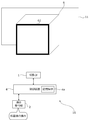
- FIG. 1 is a schematic view showing a schematic configuration of the projection device 10 of the first embodiment.
- the projection device 10 includes a projection unit 1, a control device 4, and an operation reception unit 2.
- the projection unit 1 is composed of, for example, a liquid crystal projector, a projector using LCOS (Liquid Crystal On Silicon), or the like. Hereinafter, it is assumed that the projection unit 1 is a liquid crystal projector.
- the control device 4 includes a control unit composed of various processors, a communication interface (not shown) for communicating with each unit, and a storage medium such as a hard disk, SSD (Solid State Drive), or ROM (Read Only Memory). It is a device including 4a, and controls the projection unit 1 in an integrated manner.
- a control unit composed of various processors, a communication interface (not shown) for communicating with each unit, and a storage medium such as a hard disk, SSD (Solid State Drive), or ROM (Read Only Memory). It is a device including 4a, and controls the projection unit 1 in an integrated manner.
- the circuit configuration is changed after manufacturing the CPU (Central Processing Unit), FPGA (Field Programmable Gate Array), etc., which are general-purpose processors that execute programs and perform various processes.
- a dedicated electric circuit or the like which is a processor having a circuit configuration specially designed to execute a specific process such as a programmable logic device (PLD) or an ASIC (Application Special Integrated Circuit), which is a possible processor. Is included.
- the structure of these various processors is an electric circuit that combines circuit elements such as semiconductor elements.
- the control unit of the control device 4 may be composed of one of various processors, or a combination of two or more processors of the same type or different types (for example, a combination of a plurality of FPGAs or a combination of a CPU and an FPGA). It may be composed of.
- the operation reception unit 2 detects an instruction (user instruction) from the user by receiving various operations from the user.
- the operation receiving unit 2 may be a button, a key, a joystick, or the like provided in the control device 4, or may be a receiving unit or the like that receives a signal from a remote controller that remotely controls the control device 4.
- the projected object 6 is an object having a projection surface on which a projected image is displayed by the projection unit 1.
- the projected object 6 is a rectangular parallelepiped having only one surface facing the projection device 10, and this one surface is the projection surface. It is assumed that the top, bottom, left, and right of the projected object 6 in FIG. 1 are the top, bottom, left, and right of the actual projected object 6. Further, in the example of FIG. 1, there is a wall on a plane behind the projected object 6 (in the depth direction of FIG. 1).
- the projection range 11 is a range in which the projected light is irradiated by the projection unit 1.
- the projection range 11 is rectangular. Further, in the example shown in FIG. 1, the projection range 11 is a wider range than the projection surface of the projected object 6 including the projection surface of the projected object 6.
- the content projection range is an example of the first range of the present invention.
- the user wants to set the content projection range on which the projection device 10 projects the content image over the entire projection surface of the projected object 6.
- it is necessary to set which range of the projection range 11 is the content projection range projected on the projection surface of the projection device 10 with respect to the projection device 10.
- the projection unit 1, the control device 4, and the operation reception unit 2 are realized by, for example, one device (see, for example, FIGS. 3 and 4).
- the projection unit 1, the control device 4, and the operation reception unit 2 may be separate devices that cooperate with each other by communicating with each other.
- FIG. 2 is a schematic view showing an example of the internal configuration of the projection unit 1 shown in FIG.
- the projection unit 1 includes a light source 21, an optical modulation unit 22, a projection optical system 23, and a control circuit 24.
- the light source 21 includes a light emitting element such as a laser or an LED (Light Emitting Diode), and emits white light, for example.
- a light emitting element such as a laser or an LED (Light Emitting Diode), and emits white light, for example.
- the light modulation unit 22 modulates each color light emitted from the light source 21 and separated into three colors of red, blue, and green by a color separation mechanism (not shown) based on image information, and emits each color image. It is composed of a liquid crystal panel. Red, blue, and green filters may be mounted on each of the three liquid crystal panels, and the white light emitted from the light source 21 may be modulated by each liquid crystal panel to emit each color image.
- the projection optical system 23 receives light from the light source 21 and the light modulation unit 22, and includes, for example, a relay optical system including at least one lens. The light that has passed through the projection optical system 23 is projected onto the object to be projected 6.
- the control circuit 24 controls the light source 21, the optical modulation unit 22, and the projection optical system 23 based on the display data input from the control device 4, so that the projected object 6 has an image based on the display data.
- the display data input to the control circuit 24 is composed of three components: red display data, blue display data, and green display data.
- control circuit 24 expands or contracts the projection range 11 (see FIG. 1) of the projection unit 1 by changing the projection optical system 23 based on the command input from the control device 4. Further, the control device 4 may move the projection range 11 of the projection unit 1 by changing the projection optical system 23 based on the operation from the user received by the operation reception unit 2.
- the projection device 10 includes a shift mechanism that mechanically or optically moves the projection range 11 while maintaining the image circle of the projection optical system 23.
- the image circle of the projection optical system 23 is a region in which the projected light incident on the projection optical system 23 appropriately passes through the projection optical system 23 from the points of light loss, color separation, peripheral curvature, and the like.
- the shift mechanism is realized by at least one of an optical system shift mechanism that shifts the optical system and an electron shift mechanism that performs electron shift.
- the optical system shift mechanism is, for example, a mechanism for moving the projection optical system 23 in a direction perpendicular to the optical axis (see, for example, FIGS. 3 and 4), or an optical modulation unit 22 instead of moving the projection optical system 23. It is a mechanism that moves in the direction perpendicular to the axis. Further, the optical system shift mechanism may be a combination of the movement of the projection optical system 23 and the movement of the optical modulation unit 22.
- the electronic shift mechanism is a mechanism that shifts the pseudo projection range 11 by changing the range through which light is transmitted in the optical modulation unit 22.
- the projection device 10 may include a projection direction changing mechanism that moves the projection range 11 together with the image circle of the projection optical system 23.
- the projection direction changing mechanism is a mechanism that changes the projection direction of the projection unit 1 by changing the direction of the projection unit 1 by mechanical rotation (see, for example, FIGS. 3 and 4).
- FIG. 3 is a schematic view showing an external configuration of the projection device 10.
- FIG. 4 is a schematic cross-sectional view of the optical unit 106 of the projection device 10 shown in FIG.
- FIG. 4 shows a cross section of the light emitted from the main body 101 shown in FIG. 3 along the optical path.
- the projection device 10 includes a main body portion 101 and an optical unit 106 provided so as to project from the main body portion 101.
- the operation reception unit 2, the control device 4, the light source 21, the light modulation unit 22, and the control circuit 24 in the projection unit 1 are provided in the main body 101.
- the projection optical system 23 in the projection unit 1 is provided in the optical unit 106.
- the optical unit 106 includes a first member 102 supported by the main body 101 and a second member 103 supported by the first member 102.
- the first member 102 and the second member 103 may be integrated members.
- the optical unit 106 may be detachably configured (in other words, interchangeable) on the main body 101.
- the main body 101 has a housing 15 (see FIG. 4) in which an opening 15a (see FIG. 4) for passing light is formed in a portion connected to the optical unit 106.
- a light source 21 and an optical modulation unit 22 Inside the housing 15 of the main body 101, as shown in FIG. 3, a light source 21 and an optical modulation unit 22 (a light modulation unit 22 that spatially modulates the light emitted from the light source 21 based on input image data to generate an image).
- An optical modulation unit 12 including (see FIG. 2) is provided inside the housing 15 of the main body 101.
- the light emitted from the light source 21 is incident on the optical modulation unit 22 of the optical modulation unit 12, and is spatially modulated by the optical modulation unit 22 and emitted.
- the image formed by the light spatially modulated by the light modulation unit 12 passes through the opening 15a of the housing 15 and is incident on the optical unit 106, and the projected object 6 as a projection object 6
- the image G1 becomes visible to the observer.
- the optical unit 106 includes a first member 102 having a hollow portion 2A connected to the inside of the main body 101, a second member 103 having a hollow portion 3A connected to the hollow portion 2A, and a hollow portion 2A.
- the first optical system 121 and the reflecting member 122 arranged, the second optical system 31, the reflecting member 32, the third optical system 33, and the lens 34 arranged in the hollow portion 3A, the shift mechanism 105, and the projection direction change.
- the mechanism 104 is provided.
- the first member 102 is a member having a rectangular cross-sectional outer shape as an example, and the openings 2a and 2b are formed on surfaces perpendicular to each other.
- the first member 102 is supported by the main body 101 in a state where the opening 2a is arranged at a position facing the opening 15a of the main body 101.
- the light emitted from the light modulation unit 22 of the light modulation unit 12 of the main body 101 passes through the openings 15a and 2a and is incident on the hollow portion 2A of the first member 102.
- the incident direction of the light incident on the hollow portion 2A from the main body portion 101 is described as the direction X1, the opposite direction of the direction X1 is described as the direction X2, and the direction X1 and the direction X2 are collectively referred to as the direction X.
- the direction from the front to the back of the paper and the opposite direction are described as the direction Z.
- the direction from the front to the back of the paper is described as the direction Z1
- the direction from the back to the front of the paper is described as the direction Z2.
- the direction perpendicular to the direction X and the direction Z is described as the direction Y, and among the directions Y, the upward direction in FIG. 4 is described as the direction Y1, and the downward direction in FIG. 4 is described as the direction Y2. ..
- the projection device 10 is arranged so that the direction Y2 is the vertical direction.
- the projection optical system 23 shown in FIG. 2 is composed of a first optical system 121, a reflection member 122, a second optical system 31, a reflection member 32, a third optical system 33, and a lens 34.
- FIG. 4 shows the optical axis K of the projection optical system 23.
- the first optical system 121, the reflective member 122, the second optical system 31, the reflective member 32, the third optical system 33, and the lens 34 are arranged along the optical axis K in this order from the optical modulation unit 22 side.
- the first optical system 121 includes at least one lens, and guides light traveling from the main body 101 to the first member 102 in the direction X1 to the reflecting member 122.
- the reflecting member 122 reflects the light incident from the first optical system 121 in the direction Y1.
- the reflective member 122 is composed of, for example, a mirror or the like.
- the first member 102 has an opening 2b formed on the optical path of the light reflected by the reflecting member 122, and the reflected light passes through the opening 2b and proceeds to the hollow portion 3A of the second member 103.
- the second member 103 is a member having a substantially T-shaped cross section, and an opening 3a is formed at a position facing the opening 2b of the first member 102.
- the light from the main body 101 that has passed through the opening 2b of the first member 102 is incident on the hollow portion 3A of the second member 103 through the opening 3a.
- the cross-sectional outer shape of the first member 102 and the second member 103 is arbitrary, and is not limited to the above.
- the second optical system 31 includes at least one lens, and guides the light incident from the first member 102 to the reflecting member 32.
- the reflecting member 32 reflects the light incident from the second optical system 31 in the direction X2 and guides it to the third optical system 33.
- the reflective member 32 is composed of, for example, a mirror or the like.
- the third optical system 33 includes at least one lens, and guides the light reflected by the reflecting member 32 to the lens 34.
- the lens 34 is arranged at this end so as to close the opening 3c formed at the end of the second member 103 on the direction X2 side.
- the lens 34 projects the light incident from the third optical system 33 onto the projected object 6.
- the projection direction changing mechanism 104 is a rotation mechanism that rotatably connects the second member 103 to the first member 102.
- the second member 103 is rotatably configured around a rotation axis (specifically, an optical axis K) extending in the direction Y.
- the projection direction changing mechanism 104 is not limited to the arrangement position shown in FIG. 4, as long as the optical system can be rotated. Further, the number of rotation mechanisms is not limited to one, and a plurality of rotation mechanisms may be provided.
- the shift mechanism 105 is a mechanism for moving the optical axis K (in other words, the optical unit 106) of the projection optical system in the direction perpendicular to the optical axis K (direction Y in FIG. 4). Specifically, the shift mechanism 105 is configured so that the position of the first member 102 in the direction Y with respect to the main body 101 can be changed.
- the shift mechanism 105 may be one in which the first member 102 is manually moved, or one in which the first member 102 is electrically moved.
- FIG. 4 shows a state in which the first member 102 is moved to the direction Y1 side as much as possible by the shift mechanism 105. From the state shown in FIG. 4, the first member 102 is moved in the direction Y2 by the shift mechanism 105, so that the center of the image (in other words, the center of the display surface) formed by the optical modulation unit 22 and the optical axis K are aligned with each other. The relative position changes, and the image G1 projected on the projected object 6 can be shifted (translated) in the direction Y2.
- the shift mechanism 105 may be a mechanism that moves the optical modulation unit 22 in the direction Y instead of moving the optical unit 106 in the direction Y. Even in this case, the image G1 projected on the projected object 6 can be moved in the direction Y2.
- ⁇ Procedure for projecting content image by projection device 10> 5 to 11 are diagrams showing an example of a procedure for projecting a content image by the projection device 10.
- the projection range 11 of the projection device 10 includes the projection surface of the projected object 6 as in the example of FIG. It shall be adjusted so as to.
- the projection device 10 receives the setting start operation instructing the start of setting the content projection range from the operation reception unit 2, the projection device 10 projects the numerical image 51 onto the projection range 11.
- the numerical image 51 is an example of a second image divided into a plurality of ranges.
- the numerical image 51 is divided into nine ranges in a 3 ⁇ 3 matrix. Further, in the numerical image 51, each of the plurality of divided ranges includes an identifier for the user to select the range.
- the number image 51 is an image in which the numbers “1” to “9” are included in each of the nine ranges.
- the arrangement of the numbers “1” to “9” is arbitrary. Further, the number of divisions of the numerical image 51 is not limited to 9, and can be any number of 2 or more. Further, the divided shape of the numerical image 51 is not limited to the matrix shape, and may be another divided shape. Further, the identifier is not limited to numbers such as “1” to “9", and may be various identifiers that do not overlap with each other, such as alphabets such as "A" to "I”.
- the projected object 6 is located near the center of the projection range 11, and as a result, the entire range of “5” in the center of the numerical image 51 and each other than “5”. A part of the range is a state in which is projected on the projection surface of the object to be projected 6.
- the user who adjusts the projection device 10 looks at the numerical image 51, and since the range of “5” is near the center of the projection surface of the projected object 6, “1”. -The operation of selecting "5" from “9” is performed on the operation reception unit 2. On the other hand, the projection device 10 projects the cursor 61 at a predetermined position (for example, the center) within the range of "5" of the numerical image 51.
- the projection device 10 does not project the numerical image 51 shown in FIG. 5 when projecting the cursor 61, but the cursor 61 may be projected while the numerical image 51 is projected. Then, the cursor 61 may be projected by non-projecting only a part of the numerical image 51 (for example, the number "5").
- the cursor 61 is an image that moves in the projected image according to the user operation.
- the projection of the cursor 61 can be performed, for example, by including the cursor 61 in the projected image projected on the projection range 11. As a result, the cursor 61 can be projected so as to overlap the projected image.
- the cursor 61 is a cross-shaped cursor, but the shape of the cursor 61 is not limited to this, and may be various shapes such as a quadrangle and a circle.
- the projection device 10 projects the projection image including the cursor 61 at the position of the range selected by the user operation in the numerical image 51. As a result, it is possible to prevent the cursor 61 from being projected to a position other than the projected object 6 and making it difficult for the user to find the cursor 61.
- the cursor 61 projects onto the projected object 6 by performing an operation of selecting a number projected on the projected object 6 from each of the numbers of the numerical image 51. Therefore, it is possible to prevent the cursor 61 from being projected at a position other than the projected object 6.
- the user performs a movement operation for moving the cursor 61 on the operation reception unit 2.
- the user performs a movement operation so that the cursor 61 moves to the lower left of the projection surface of the projection object 6.
- the projection device 10 moves the cursor 61 in the direction and amount according to the received movement operation.
- the movement of the cursor 61 can be performed, for example, by changing the position including the cursor 61 in the projected image projected on the projection range 11.
- the user performs a duplication operation for duplicating the cursor 61 on the operation reception unit 2.
- the projection device 10 duplicates the cursor 61.
- the duplication of the cursor 61 can be performed, for example, by adding the cursor 61 to be included in the projected image projected on the projection range 11.
- the processing corresponding to the above-mentioned movement operation and duplication operation is performed on the cursor 61 selected as the selection cursor among the plurality of cursors 61.
- the user can switch the selection cursor among the plurality of cursors 61 by performing the selection cursor switching operation instructing the operation reception unit 2 to switch the selection cursor among the plurality of cursors 61.
- the user repeatedly performs the cursor operation including the above-mentioned movement operation, duplication operation, and selection cursor switching operation, thereby arranging the cursors 61 at the four corners of the projection surface of the projected object 6. do.
- the user performs a confirmation operation instructing the operation reception unit 2 to determine the range specified by the current cursor 61 as the content projection range.
- the projection device 10 sets a rectangular range having four corners at each position where the four cursors 61 are arranged in FIG. 9 as the content projection range 11a.
- the content projection range 11a is virtually shown by a thick line.
- the user performs a content projection operation instructing the operation reception unit 2 to start projecting the content image onto the content projection range 11a.
- the projection device 10 generates a content image 111 that matches the set content projection range 11a, and starts projecting the generated content image 111 onto the content projection range 11a.
- the content image 111 is a moving image showing a state in which a large number of fish are swimming.
- the content image 111 is not limited to this, and may be any still image or moving image.
- FIG. 12 is a flowchart showing an example of the content image projection process by the control device 4.
- the control device 4 executes, for example, the projection process shown in FIG.
- the control device 4 starts the projection process shown in FIG. 12 triggered by the above setting start operation.
- the projection range 11 of the projection device 10 is adjusted to include the projection surface of the object to be projected 6, as in the examples of FIGS. 5 to 10.
- control device 4 sets a range in which the numerical image 51 (second image) is projected out of the projection range 11 (step S1201). For example, the control device 4 sets the entire range of the projection range 11 as the range in which the projection unit 1 projects the numerical image 51.
- control device 4 may set a part of the projection range 11 as a range for projecting the numerical image 51 according to a user operation or the like.
- the control device 4 receives the designation of a part of the projection range 11 such as the upper half, the lower half, the right half, and the left half from the operation reception unit 2, and projects the received range with the numerical image 51. It may be set as a range to be used.
- the user grasps the approximate position of the projection surface of the projected object 6 in the projection range 11 by projecting the numerical image 51 into the range selected by the user operation in the projection range 11.
- the numerical image 51 can be projected in a limited range, and the initial display position of the cursor 61 can be efficiently set.
- control device 4 generates the numerical image 51 (step S1202). That is, the control device 4 sets the shape of the number image 51, the number of divisions of the range of the number image 51, the identifier attached to each range of the number image 51, and the like.
- the information of the numerical image 51 is stored in the memory of the control device 4 in advance, and the control device 4 generates the numerical image 51 by reading this information.
- control device 4 may generate a numerical image 51 divided according to the user operation.
- the projection device 10 generates the numerical image 51 by receiving the setting of the maximum number of the numerical image 51 or the number of divisions of the range in the numerical image 51 from the operation reception unit 2.
- the operation reception unit 2 As a result, it is possible to flexibly generate a numerical image 51 divided according to the user operation with respect to the projection surface of the object 6 having various sizes and shapes.
- control device 4 may generate a numerical image 51 divided based on the size of the projection range 11. For example, the control device 4 generates a numerical image 51 divided into many ranges as the projection range 11 becomes larger. As a result, for example, when the projection range 11 is large, the numerical image 51 divided into many ranges can be projected, so that each range of the numerical image 51 becomes too large and it becomes difficult to specify the range on which the cursor 61 is projected. Can be avoided.
- the control device 4 may generate a numerical image 51 divided based on the shape of the projection range 11. For example, in the control device 4, when the projection range 11 is a vertically long rectangular shape, the number of divisions in the vertical direction is larger than the number of divisions in the horizontal direction (that is, the number of division lines in the horizontal direction is larger than the number of division lines in the vertical direction). 51 is generated. Further, when the projection range 11 is a horizontally long rectangle, the control device 4 generates a numerical image 51 in which the number of divisions in the horizontal direction is larger than the number of divisions in the vertical direction.
- the projection range 11 is a vertically long rectangle
- the numerical image 51 divided into many ranges in the vertical direction can be projected, so that the cursor 61 becomes too large in the vertical direction of each range of the numerical image 51. It is possible to avoid difficulty in specifying the projection range.
- control device 4 controls the projection unit 1 to project the numerical image 51 generated in step S1202 into the range determined in step S1201 (step S1203).
- control device 4 receives the number selected by the user from the numbers included in the number image 51 projected in step S1203 from the operation reception unit 2 (step S1204).
- the control device 4 controls the projection unit 1 to project the cursor 61 (first image) on the range corresponding to the number received in step S1204 in each range of the number image 51 (step S1205). ..
- control device 4 determines whether or not the operation reception unit 2 has accepted the cursor operations such as the above-mentioned movement operation, duplication operation, and selection cursor switching operation (step S1206).
- the control device 4 processes the cursor 61 according to the accepted cursor operation (step S1207), and proceeds to step S1208.
- step S1206 determines whether or not the above confirmation operation has been accepted from the operation reception unit 2 (step S1208). If the confirmation operation is not accepted (step S1208: No), the control device 4 returns to step S1206.
- step S1208 When the confirmation operation is accepted in step S1208 (step S1208: Yes), the control device 4 sets the content projection range (first range) based on the cursor 61 at that time (step S1209).
- control device 4 generates a content image that matches the content projection range set in step S1209 (step S1210).
- the control device 4 generates a content image that matches the content projection range by performing processing such as enlargement, reduction, and trimming on the original content image.
- control device 4 controls the projection unit 1 to start projecting the content image generated in step S1210 onto the content projection range set in step S1209 (step S1211), and ends a series of processes. ..
- control device 4 may project the content image after receiving the above-mentioned content projection operation from the operation reception unit 2.
- control device 4 may, for example, project the cursor 61 in step S1205, then receive an operation instructing the reception of numbers to be redone from the operation reception unit 2, and if this operation is received, return to step S1203. .
- the control device 4 receives, for example, an operation for instructing the setting of the content projection range 11a to be redone after starting the projection of the content image 111 by the reflective member 122, and accepting this operation, the control device 4 receives the operation. You may return to step S1203 or step S1206.
- FIG. 13 is a diagram showing a modified example of the projection of the content image by the projection device 10.
- the projection device 10 may project an image that is uniformly black in the peripheral range 11c other than the content projection range 11a in the projection range 11.
- the control device 4 makes the portion corresponding to the peripheral range 11c in the projected image projected on the projection range 11 black.
- no light is projected from the projection unit 1 onto the peripheral range 11c, and the peripheral range 11c is uniformly black. Therefore, even if there is an object such as a wall behind the projected object 6, the observer can easily recognize the range of the content image 111.
- the projection device 10 does not transmit light to the peripheral range 11c, but may project an image different from the content image 111 on the peripheral range 11c.
- the projection device 10 sets a portion of the projected image projected on the projection range 11 corresponding to the peripheral range 11c as an image of a uniform color (for example, gray) or a fixed pattern (for example, a fine lattice pattern). It may be an image.
- a uniform color for example, gray
- a fixed pattern for example, a fine lattice pattern
- ⁇ Range setting for deformation example 1 of the projected object 6 by the projection device 10> 14 and 15 are diagrams showing an example of range setting for the modified example 1 of the projected object 6 by the projection device 10.
- the projected object 6 is a rectangular parallelepiped
- the shape of the projected object 6 is not limited to this.
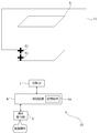
- the projected object 6 may be a cylindrical object as shown in FIG.
- the side surface (curved surface) of the object to be projected 6 that can be seen from the side of the projection device 10 is used as the projection surface
- the user sets the shape of the side surface (for example, the side surface of a cylinder) for the projection device 10 with respect to the projection device 10.
- the projection device 10 first projects the number image 51 and projects the cursor 61 based on the result of receiving the designation of the number from the user.
- the user arranges the cursor 61 so as to surround the desired projection surface on the projected object 6 by performing the above-mentioned various cursor operations on the operation receiving unit 2.
- ten cursors 61 are used to enclose the entire range of the projected object 6 that can be seen from the side of the projection device 10.
- the projection device 10 sets the range surrounded by the cursor 61 as the content projection range 11a.
- the projection device 10 sets the content projection range 11a, which is a curved surface, by using linear interpolation based on each position of the plurality of cursors 61.
- the projection device 10 generates the content image 111 in accordance with the content projection range 11a, and projects the generated content image 111 onto the content projection range 11a.
- the projection device 10 may perform distortion correction according to the curved surface of the content projection range 11a according to the user operation.
- ⁇ Range setting for deformation example 2 of the projected object 6 by the projection device 10> 16 and 17 are diagrams showing an example of range setting for the second modification of the projected object 6 by the projection device 10.
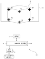
- the projected object 6 is a rectangular parallelepiped, and two surfaces of the projected object 6 face the projection device 10, and these two surfaces may be used as projection surfaces.
- the user sets the shape of this side surface (for example, two adjacent faces of a rectangular parallelepiped) with respect to the projection device 10.
- the projection device 10 first projects the number image 51 and projects the cursor 61 based on the result of receiving the designation of the number from the user.
- the user arranges the cursor 61 so as to surround the desired projection surface on the projected object 6 by performing the above-mentioned various cursor operations on the operation receiving unit 2.
- six cursors 61 are used to enclose a range of the projected object 6 including two surfaces that can be seen from the side of the projection device 10.
- the projection device 10 sets the range surrounded by the cursor 61 as the content projection range 11a. Then, the projection device 10 generates the content image 111 in accordance with the content projection range 11a, and projects the generated content image 111 onto the content projection range 11a. When the content image 111 is generated, the projection device 10 may perform distortion correction according to the angle of each of the two surfaces included in the content projection range 11a according to the user operation.
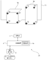
- FIG. 18 is a diagram showing another example of range setting for the modified example 2 of the projected object 6 by the projection device 10.
- the projection device 10 sets the content projection ranges 11a and 11b for projecting the two content images 111 based on the respective positions of the cursor 61. You may.
- the content projection ranges 11a and 11b are two surfaces of the projected object 6 facing the projection device 10.
- the projection device 10 generates two content images 111 according to the content projection ranges 11a and 11b, and projects the generated two content images 111 onto the content projection ranges 11a and 11b, respectively.
- the two content images 111 may be each image obtained by dividing the image of one content image into two, or may be content images independent of each other.
- the projection device 10 can instruct a plurality of first ranges (for example, content projection ranges 11a and 11b) by the cursor 61, and different images may be projected as content images on the plurality of first ranges. ..
- the two content images 111 projected on the content projection ranges 11a and 11b may be the same content image.
- the projection device 10 may perform distortion correction according to the angle of each of the two surfaces of the content projection ranges 11a and 11b according to the user operation when generating the two content images 111.
- FIG. 16 which of FIG. 17 and FIG. 18 is the setting result of the content projection range when the user performs the confirmation operation may be set according to the user operation. ..
- the setting result shown in FIG. 17 and the setting result shown in FIG. 18 may be switched according to the user operation.
- the content image 111 may be projected on a plurality of projected objects.
- the projection device 10 may perform projection on one surface of each of the objects to be projected 6a and 6b.
- the projected objects 6a and 6b are rectangular parallelepipeds having different shapes from each other.
- the user sets the shape of the side surface of the projection device 10 (for example, one side of each of the two rectangular parallelepipeds) with respect to the projection device 10.
- the projection device 10 first projects the number image 51 and projects the cursor 61 based on the result of receiving the designation of the number from the user.
- the user arranges the cursor 61 so as to surround the desired projection plane on the projected objects 6a and 6b by performing the above-mentioned various cursor operations on the operation receiving unit 2.
- eight cursors 61 are used to enclose one surface of each of the projected objects 6a and 6b.
- the projection device 10 sets each range surrounded by the cursor 61 as the content projection ranges 11a and 11b. Then, the projection device 10 generates two content images 111 according to the content projection ranges 11a and 11b, and projects the generated two content images 111 onto the content projection ranges 11a and 11b, respectively. When the content image 111 is generated, the projection device 10 may perform distortion correction according to the angle of each of the two surfaces of the content projection ranges 11a and 11b according to the user operation.
- ⁇ Modification example of the first image for the user to indicate the content projection range> 21 and 22 are diagrams showing a modified example of the first image for the user to indicate the content projection range.
- the cursor 61 has been described as an example as the first image for the user to indicate the content projection range, the first image is not limited to the cursor 61.
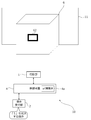
- the first image may be the frame image 62 shown in FIG.
- the projection device 10 moves to a predetermined position (for example, the center) within the range of "5" of the numerical image 51.
- the frame image 62 is projected onto the image.
- the frame image 62 is an image that can be moved, enlarged, enlarged / reduced, deformed, and the like by user operation.
- the user adjusts the frame image 62 to the four sides of the projection surface of the projected object 6 by performing the operation of the frame image 62 on the operation receiving unit 2.
- the projection device 10 sets the rectangular range surrounded by the frame image 62 as the content projection range 11a.
- the projection surface of the object to be projected 6 is set as the content projection range 11a, as in the example of FIG.
- the operation reception unit 2 may be able to perform a duplication operation for duplicating the frame image 62 so that a plurality of content projection ranges (for example, content projection ranges 11a and 11b) can be set.
- the projection device 10 positions the first image for the user to indicate the first range for projecting the content image at a position corresponding to the user operation (for example, the operation of selecting a number based on the numerical image 51). It is projected from the projection unit 1 so as to overlap the projected image, and the first range is set according to the user operation on the first image. This prevents the first image for the user to indicate the first range on which the content image is projected to be projected at a position different from the projected object, which makes it difficult for the user to find the first image. be able to. Therefore, it is possible to easily set the range for projecting the content image.
- the second image divided into a plurality of ranges a numerical image 51 in which an identifier such as a number is attached to each range has been described as an example, but the second image is not limited to this.
- the second image may be an image that is divided into a plurality of ranges and has no identifier.
- the projection device 10 highlights one of the plurality of ranges of the second image and instructs the user to switch the highlighted range, and the highlighted range is the numerical image 51. Accepts a user operation instructing to select as the initial projection range.
- the initial projection range of the numerical image 51 can be set even if there is no identifier.
- the first image for the user to indicate the first range for projecting the content image is projected from the projection unit 1 at a position other than the end portion of the projection range 11 so as to overlap the projected image. Let me.
- FIG. 23 is a flowchart showing an example of the content image projection process by the control device 4 of the second embodiment.
- the control device 4 executes, for example, the projection process shown in FIG. 23.
- the control device 4 starts the projection process shown in FIG. 23, triggered by the above setting start operation.
- the projection range 11 of the projection device 10 is adjusted to include the projection surface of the object to be projected 6, as in the examples of FIGS. 5 to 10.
- control device 4 controls the projection unit 1 to project the cursor 61 at the center of the projection range 11 (step S231). In this case, the control device 4 does not have to perform the process of projecting the above-mentioned numerical image 51.
- Steps S232 to S237 shown in FIG. 23 are the same as steps S1206 to S1211 shown in FIG.
- the projection device 10 projects the cursor 61 (first image) for the user to indicate the content projection range 11a for projecting the content image 111 to the center of the projection range 11.
- the cursor 61 is projected to a position other than the projection surface of the projection object 6 by roughly aligning the center of the projection range 11 and the center of the projection surface of the projection object 6.
- the projection position of the cursor 61 is not limited to the center of the projection range 11, but may be a predetermined position other than the center of the projection range 11 (for example, a position slightly below the center of the projection range 11). can.
- the above processor A first image for the user to indicate the first range is projected from the projection unit at a position corresponding to the user operation so as to overlap the projected image.
- a control for setting the first range is executed according to a user operation on the first image. Control method.
- the second image is a projection image in which each of the plurality of ranges includes an identifier for the user to select the range. Control method.
- the control method according to (2) or (3) The second image is a projected image divided according to the user operation. Control method.
- the second image is a projection image divided according to the size of the projection range. Control method.
- the control method according to any one of (2) to (5) is a projection image divided according to the shape of the projection range. Control method.
- the control method according to any one of (2) to (6).
- the processor executes control to project the second image from the projection unit in a range selected by the user operation in the projection range. Control method.
- the control method according to any one of (1) to (7).
- the first image includes a cursor that moves within the projected image in response to a user operation. Control method.
- the cursor is a cursor that can be duplicated in the projected image according to a user operation. Control method.
- control method according to any one of (1) to (9).
- a plurality of first ranges can be specified by the first image.
- the processor executes control for projecting different images as the content images on the plurality of first ranges. Control method.
- the control method according to any one of (1) to (10).
- the processor executes control that does not project light from the projection unit or projects an image different from the content image on a range of the projection range that is different from the first range. Control method.
- a projection device that includes a projection unit and a processor and projects a content image into a set first range of the projection range of the projection unit.
- the above processor A first image for the user to indicate the first range is projected from the projection unit at a position corresponding to the user operation so as to overlap the projected image.
- a control for setting the first range is executed according to a user operation on the first image. Projection device.
- a control program for a projection device that includes a projection unit and a processor and projects a content image onto a set first range of the projection ranges of the projection unit.
- a first image for the user to indicate the first range is projected from the projection unit at a position corresponding to the user operation so as to overlap the projected image.
- the first range is set according to the user operation for the first image.
- the above processor A first image for the user to indicate the first range is projected from the projection unit at a position other than the end portion so as to overlap the projected image.
- a control for setting the first range is executed according to a user operation on the first image. Control method.
- a projection device that includes a projection unit and a processor and projects a content image into a set first range of the projection range of the projection unit.
- the above processor A first image for the user to indicate the first range is projected from the projection unit at a position other than the end portion so as to overlap the projected image.
- a control for setting the first range is executed according to a user operation on the first image. Projection device.
- a control program for a projection device that includes a projection unit and a processor and projects a content image onto a set first range of the projection ranges of the projection unit.
- a first image for the user to indicate the first range is projected from the projection unit at a position other than the end portion so as to overlap the projected image.
- the first range is set according to the user operation for the first image.
- Projection unit 2 Operation reception unit 2A, 3A Hollow part 2a, 2b, 3a, 3c, 15a Opening 4 Control device 4a Storage medium 6,6a, 6b Projected object 10 Projecting device 11 Projection range 11a, 11b Content projection range 11c Peripheral Range 12
- Optical modulation unit 15 Housing 21
- Light source 22 Optical modulation unit 23
- Projection optical system 24 Control circuit 31
- Third optical system 34 Lens 51 Numerical image 61 Cursor 62 Frame image 101 Main body 102 First member 103 Second member 104
- Projection direction change mechanism 105 Shift mechanism 106
- Optical unit 111 Content image 121 First optical system G1 image
Landscapes
- Engineering & Computer Science (AREA)
- Physics & Mathematics (AREA)
- General Physics & Mathematics (AREA)
- Computer Hardware Design (AREA)
- Theoretical Computer Science (AREA)
- Multimedia (AREA)
- Signal Processing (AREA)
- Geometry (AREA)
- Transforming Electric Information Into Light Information (AREA)
- Controls And Circuits For Display Device (AREA)
- Projection Apparatus (AREA)
Priority Applications (2)
| Application Number | Priority Date | Filing Date | Title |
|---|---|---|---|
| JP2022516879A JP7336027B2 (ja) | 2020-04-24 | 2021-03-03 | 制御方法、投影装置、及び制御プログラム |
| US18/047,074 US20230064575A1 (en) | 2020-04-24 | 2022-10-17 | Control method, projection apparatus, and control program |
Applications Claiming Priority (2)
| Application Number | Priority Date | Filing Date | Title |
|---|---|---|---|
| JP2020-077533 | 2020-04-24 | ||
| JP2020077533 | 2020-04-24 |
Related Child Applications (1)
| Application Number | Title | Priority Date | Filing Date |
|---|---|---|---|
| US18/047,074 Continuation US20230064575A1 (en) | 2020-04-24 | 2022-10-17 | Control method, projection apparatus, and control program |
Publications (1)
| Publication Number | Publication Date |
|---|---|
| WO2021215124A1 true WO2021215124A1 (ja) | 2021-10-28 |
Family
ID=78270480
Family Applications (1)
| Application Number | Title | Priority Date | Filing Date |
|---|---|---|---|
| PCT/JP2021/008306 Ceased WO2021215124A1 (ja) | 2020-04-24 | 2021-03-03 | 制御方法、投影装置、及び制御プログラム |
Country Status (3)
| Country | Link |
|---|---|
| US (1) | US20230064575A1 (https=) |
| JP (1) | JP7336027B2 (https=) |
| WO (1) | WO2021215124A1 (https=) |
Citations (6)
| Publication number | Priority date | Publication date | Assignee | Title |
|---|---|---|---|---|
| JP2004048694A (ja) * | 2002-05-20 | 2004-02-12 | Seiko Epson Corp | 投写型画像表示システム、プロジェクタ、プログラム、情報記憶媒体および画像投写方法 |
| JP2007215029A (ja) * | 2006-02-10 | 2007-08-23 | Sharp Corp | 画像投影方法及びプロジェクタ |
| JP2009225432A (ja) * | 2008-02-22 | 2009-10-01 | Panasonic Electric Works Co Ltd | 光投影装置、照明装置 |
| JP2010130385A (ja) * | 2008-11-28 | 2010-06-10 | Sharp Corp | 画像表示方法及び画像表示装置 |
| JP2013140266A (ja) * | 2012-01-05 | 2013-07-18 | Seiko Epson Corp | 表示装置、及び、表示制御方法 |
| JP2014103518A (ja) * | 2012-11-19 | 2014-06-05 | Casio Comput Co Ltd | 投影装置、投影状態調整方法、及び投影状態調整プログラム |
Family Cites Families (3)
| Publication number | Priority date | Publication date | Assignee | Title |
|---|---|---|---|---|
| JP2009048022A (ja) * | 2007-08-21 | 2009-03-05 | Funai Electric Co Ltd | プロジェクタ |
| KR101526995B1 (ko) * | 2008-10-15 | 2015-06-11 | 엘지전자 주식회사 | 이동 단말기 및 이것의 디스플레이 제어 방법 |
| JP2011170296A (ja) * | 2010-02-22 | 2011-09-01 | Panasonic Electric Works Co Ltd | 光投影装置 |
-
2021
- 2021-03-03 WO PCT/JP2021/008306 patent/WO2021215124A1/ja not_active Ceased
- 2021-03-03 JP JP2022516879A patent/JP7336027B2/ja active Active
-
2022
- 2022-10-17 US US18/047,074 patent/US20230064575A1/en not_active Abandoned
Patent Citations (6)
| Publication number | Priority date | Publication date | Assignee | Title |
|---|---|---|---|---|
| JP2004048694A (ja) * | 2002-05-20 | 2004-02-12 | Seiko Epson Corp | 投写型画像表示システム、プロジェクタ、プログラム、情報記憶媒体および画像投写方法 |
| JP2007215029A (ja) * | 2006-02-10 | 2007-08-23 | Sharp Corp | 画像投影方法及びプロジェクタ |
| JP2009225432A (ja) * | 2008-02-22 | 2009-10-01 | Panasonic Electric Works Co Ltd | 光投影装置、照明装置 |
| JP2010130385A (ja) * | 2008-11-28 | 2010-06-10 | Sharp Corp | 画像表示方法及び画像表示装置 |
| JP2013140266A (ja) * | 2012-01-05 | 2013-07-18 | Seiko Epson Corp | 表示装置、及び、表示制御方法 |
| JP2014103518A (ja) * | 2012-11-19 | 2014-06-05 | Casio Comput Co Ltd | 投影装置、投影状態調整方法、及び投影状態調整プログラム |
Also Published As
| Publication number | Publication date |
|---|---|
| JP7336027B2 (ja) | 2023-08-30 |
| JPWO2021215124A1 (https=) | 2021-10-28 |
| US20230064575A1 (en) | 2023-03-02 |
Similar Documents
| Publication | Publication Date | Title |
|---|---|---|
| US20150077645A1 (en) | Image-projection module | |
| CN103731621A (zh) | 图像显示装置及其的图像调整方法 | |
| CN115113216A (zh) | 检测装置、检测方法以及空间投影装置 | |
| CN111816103A (zh) | 投影装置及影像调整方法 | |
| JP2008287114A (ja) | 画像投射装置及び画像投射方法 | |
| JP6019810B2 (ja) | 表示装置、撮影方法、および表示方法 | |
| US11889238B2 (en) | Projection apparatus, projection method, and control program | |
| JP7379676B2 (ja) | 制御方法、投影装置、及び制御プログラム | |
| JP7336027B2 (ja) | 制御方法、投影装置、及び制御プログラム | |
| US12041392B2 (en) | Projection system, projection method, and control program | |
| JP7350898B2 (ja) | 投影装置、投影方法、及び制御プログラム | |
| JP7300054B2 (ja) | 投影装置、投影方法、及び制御プログラム | |
| JP2008052063A (ja) | 光源装置及びプロジェクタ | |
| JP2017227803A (ja) | 画像投写装置及び画像位置調整装置 | |
| JP7721342B2 (ja) | 投影装置、投影方法、制御装置、及び制御プログラム | |
| JP4967573B2 (ja) | 画像投影装置 | |
| JP2014109610A (ja) | プラネタリウム装置 | |
| JP3515539B2 (ja) | 微小凹面鏡アレイ及び三次元映像表示装置 | |
| JP2019132939A (ja) | プロジェクターおよびプロジェクターの制御方法 | |
| JP7623893B2 (ja) | 投影装置及び制御方法 | |
| US20240004209A1 (en) | Multi-aperture projector | |
| US20250286983A1 (en) | Projection apparatus, projection system, control method, and control program | |
| JP2015118199A (ja) | 投影装置及び投影方法 | |
| JP2008170760A (ja) | プロジェクタ | |
| JP2009284135A (ja) | 投影像の台形歪み補正方法およびプロジェクタ |
Legal Events
| Date | Code | Title | Description |
|---|---|---|---|
| 121 | Ep: the epo has been informed by wipo that ep was designated in this application |
Ref document number: 21793273 Country of ref document: EP Kind code of ref document: A1 |
|
| ENP | Entry into the national phase |
Ref document number: 2022516879 Country of ref document: JP Kind code of ref document: A |
|
| NENP | Non-entry into the national phase |
Ref country code: DE |
|
| 122 | Ep: pct application non-entry in european phase |
Ref document number: 21793273 Country of ref document: EP Kind code of ref document: A1 |