WO2021215124A1 - Control method, projection device, and control program - Google Patents
Control method, projection device, and control program Download PDFInfo
- Publication number
- WO2021215124A1 WO2021215124A1 PCT/JP2021/008306 JP2021008306W WO2021215124A1 WO 2021215124 A1 WO2021215124 A1 WO 2021215124A1 JP 2021008306 W JP2021008306 W JP 2021008306W WO 2021215124 A1 WO2021215124 A1 WO 2021215124A1
- Authority
- WO
- WIPO (PCT)
- Prior art keywords
- projection
- image
- range
- projected
- control method
- Prior art date
Links
Images


Classifications
-
- H—ELECTRICITY
- H04—ELECTRIC COMMUNICATION TECHNIQUE
- H04N—PICTORIAL COMMUNICATION, e.g. TELEVISION
- H04N9/00—Details of colour television systems
- H04N9/12—Picture reproducers
- H04N9/31—Projection devices for colour picture display, e.g. using electronic spatial light modulators [ESLM]
- H04N9/3179—Video signal processing therefor
- H04N9/3185—Geometric adjustment, e.g. keystone or convergence
-
- G—PHYSICS
- G03—PHOTOGRAPHY; CINEMATOGRAPHY; ANALOGOUS TECHNIQUES USING WAVES OTHER THAN OPTICAL WAVES; ELECTROGRAPHY; HOLOGRAPHY
- G03B—APPARATUS OR ARRANGEMENTS FOR TAKING PHOTOGRAPHS OR FOR PROJECTING OR VIEWING THEM; APPARATUS OR ARRANGEMENTS EMPLOYING ANALOGOUS TECHNIQUES USING WAVES OTHER THAN OPTICAL WAVES; ACCESSORIES THEREFOR
- G03B21/00—Projectors or projection-type viewers; Accessories therefor
- G03B21/14—Details
- G03B21/26—Projecting separately subsidiary matter simultaneously with main image
-
- G—PHYSICS
- G09—EDUCATION; CRYPTOGRAPHY; DISPLAY; ADVERTISING; SEALS
- G09G—ARRANGEMENTS OR CIRCUITS FOR CONTROL OF INDICATING DEVICES USING STATIC MEANS TO PRESENT VARIABLE INFORMATION
- G09G5/00—Control arrangements or circuits for visual indicators common to cathode-ray tube indicators and other visual indicators
- G09G5/08—Cursor circuits
-
- G—PHYSICS
- G09—EDUCATION; CRYPTOGRAPHY; DISPLAY; ADVERTISING; SEALS
- G09G—ARRANGEMENTS OR CIRCUITS FOR CONTROL OF INDICATING DEVICES USING STATIC MEANS TO PRESENT VARIABLE INFORMATION
- G09G5/00—Control arrangements or circuits for visual indicators common to cathode-ray tube indicators and other visual indicators
- G09G5/36—Control arrangements or circuits for visual indicators common to cathode-ray tube indicators and other visual indicators characterised by the display of a graphic pattern, e.g. using an all-points-addressable [APA] memory
- G09G5/37—Details of the operation on graphic patterns
- G09G5/377—Details of the operation on graphic patterns for mixing or overlaying two or more graphic patterns
-
- G—PHYSICS
- G09—EDUCATION; CRYPTOGRAPHY; DISPLAY; ADVERTISING; SEALS
- G09G—ARRANGEMENTS OR CIRCUITS FOR CONTROL OF INDICATING DEVICES USING STATIC MEANS TO PRESENT VARIABLE INFORMATION
- G09G5/00—Control arrangements or circuits for visual indicators common to cathode-ray tube indicators and other visual indicators
- G09G5/36—Control arrangements or circuits for visual indicators common to cathode-ray tube indicators and other visual indicators characterised by the display of a graphic pattern, e.g. using an all-points-addressable [APA] memory
- G09G5/38—Control arrangements or circuits for visual indicators common to cathode-ray tube indicators and other visual indicators characterised by the display of a graphic pattern, e.g. using an all-points-addressable [APA] memory with means for controlling the display position
-
- H—ELECTRICITY
- H04—ELECTRIC COMMUNICATION TECHNIQUE
- H04N—PICTORIAL COMMUNICATION, e.g. TELEVISION
- H04N9/00—Details of colour television systems
- H04N9/12—Picture reproducers
- H04N9/31—Projection devices for colour picture display, e.g. using electronic spatial light modulators [ESLM]
- H04N9/3179—Video signal processing therefor
- H04N9/3188—Scale or resolution adjustment
-
- G—PHYSICS
- G09—EDUCATION; CRYPTOGRAPHY; DISPLAY; ADVERTISING; SEALS
- G09G—ARRANGEMENTS OR CIRCUITS FOR CONTROL OF INDICATING DEVICES USING STATIC MEANS TO PRESENT VARIABLE INFORMATION
- G09G2320/00—Control of display operating conditions
- G09G2320/06—Adjustment of display parameters
- G09G2320/0606—Manual adjustment
-
- G—PHYSICS
- G09—EDUCATION; CRYPTOGRAPHY; DISPLAY; ADVERTISING; SEALS
- G09G—ARRANGEMENTS OR CIRCUITS FOR CONTROL OF INDICATING DEVICES USING STATIC MEANS TO PRESENT VARIABLE INFORMATION
- G09G2340/00—Aspects of display data processing
- G09G2340/04—Changes in size, position or resolution of an image
-
- G—PHYSICS
- G09—EDUCATION; CRYPTOGRAPHY; DISPLAY; ADVERTISING; SEALS
- G09G—ARRANGEMENTS OR CIRCUITS FOR CONTROL OF INDICATING DEVICES USING STATIC MEANS TO PRESENT VARIABLE INFORMATION
- G09G2354/00—Aspects of interface with display user
-
- G—PHYSICS
- G09—EDUCATION; CRYPTOGRAPHY; DISPLAY; ADVERTISING; SEALS
- G09G—ARRANGEMENTS OR CIRCUITS FOR CONTROL OF INDICATING DEVICES USING STATIC MEANS TO PRESENT VARIABLE INFORMATION
- G09G3/00—Control arrangements or circuits, of interest only in connection with visual indicators other than cathode-ray tubes
- G09G3/001—Control arrangements or circuits, of interest only in connection with visual indicators other than cathode-ray tubes using specific devices not provided for in groups G09G3/02 - G09G3/36, e.g. using an intermediate record carrier such as a film slide; Projection systems; Display of non-alphanumerical information, solely or in combination with alphanumerical information, e.g. digital display on projected diapositive as background
- G09G3/002—Control arrangements or circuits, of interest only in connection with visual indicators other than cathode-ray tubes using specific devices not provided for in groups G09G3/02 - G09G3/36, e.g. using an intermediate record carrier such as a film slide; Projection systems; Display of non-alphanumerical information, solely or in combination with alphanumerical information, e.g. digital display on projected diapositive as background to project the image of a two-dimensional display, such as an array of light emitting or modulating elements or a CRT
Definitions
- the present invention relates to a control method, a projection device, and a control program.
- Patent Document 1 regarding the geometric correction related to the projection on the cylindrical surface, the range of the image area including the image in the projection range is specified by the user with a corner marker or the like, and the image area is matched with the target area of the cylinder.
- the projection device configured in is described.
- Patent Document 2 when an image is projected so as to straddle two surfaces intersecting each other at an angle, each of the two parts obtained by dividing the projected image by a straight line is individually distorted. An image processing apparatus configured to do so is described.
- One embodiment according to the technique of the present disclosure provides a control method, a projection device, and a control program that facilitates setting of a range for projecting a content image.
- the projection method of one embodiment according to the technique of the present disclosure is a control method of a projection system including a projection unit and a processor and projecting a content image into a set first range of the projection ranges of the projection unit.
- the processor projects a first image for the user to indicate the first range from the projection unit so as to overlap the projected image at a position corresponding to the user operation, and responds to the user operation on the first image.
- the control for setting the first range is executed.
- the projection device of one embodiment according to the technique of the present disclosure is a projection device including a projection unit and a processor, and projects a content image in a set first range of the projection range of the projection unit.
- the first image for the user to indicate the first range is projected from the projection unit at a position corresponding to the user operation so as to overlap the projected image, and the first image is projected according to the user operation on the first image. It executes the control to set one range.
- the control program of one embodiment according to the technique of the present disclosure is a control program of a projection device including a projection unit and a processor and projecting a content image into a set first range of the projection ranges of the projection unit.
- the processor is projected from the projection unit so as to overlap the projected image at a position corresponding to the user operation, and the first image for the user instructing the first range is projected from the projection unit in response to the user operation on the first image.
- the purpose is to execute the process of setting the first range.
- Another projection method of one embodiment according to the technique of the present disclosure is a control method of a projection system including a projection unit and a processor and projecting a content image into a set first range of the projection ranges of the projection unit. Therefore, the processor projects the first image for the user to indicate the first range from the projection unit so as to overlap the projected image at a position other than the end portion, and the user operates the first image.
- the control for setting the first range is executed accordingly.
- Another projection device of one embodiment according to the technique of the present disclosure is a projection device that includes a projection unit and a processor and projects a content image into a set first range of the projection ranges of the projection unit.
- the processor projects a first image for the user to indicate the first range from the projection unit so as to overlap the projected image at a position other than the end portion, and responds to the user's operation on the first image. It executes the control to set the first range.
- Another control program of one embodiment according to the technique of the present disclosure is a control program of a projection device that includes a projection unit and a processor and projects a content image in a set first range of the projection ranges of the projection unit. Therefore, the processor is made to project the first image for the user to indicate the first range from the projection unit so as to overlap the projected image at a position other than the end portion, and the user can operate the first image. The purpose is to execute the process of setting the first range accordingly.
- FIG. 3 is a schematic cross-sectional view of the optical unit 106 of the projection device 10 shown in FIG. It is a figure (the 1) which shows an example of the projection procedure of the content image by the projection apparatus 10. It is a figure (the 2) which shows an example of the projection procedure of the content image by the projection apparatus 10.
- FIG. 3 is a diagram (No. 3) showing an example of a procedure for projecting a content image by the projection device 10.
- FIG. 5 is a diagram (No. 5) showing an example of a procedure for projecting a content image by the projection device 10.
- FIG. 6 is a diagram (No. 6) showing an example of a procedure for projecting a content image by the projection device 10.
- FIG. 7 is a diagram (No. 7) showing an example of a procedure for projecting a content image by the projection device 10. It is a flowchart which shows an example of the projection processing of the content image by the control device 4. It is a figure which shows the modification of the projection of the content image by the projection device 10.
- the 1 which shows an example of the range setting with respect to the modification 1 of the projection object 6 by a projection apparatus 10.
- the 2 which shows an example of the range setting with respect to the modification 1 of the projection object 6 by a projection apparatus 10.
- the 1 which shows an example of the range setting with respect to the modification 2 of the projection object 6 by a projection apparatus 10.
- the 2 which shows an example of the range setting with respect to the modification 2 of the projection object 6 by a projection apparatus 10.
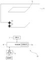
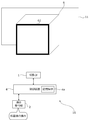
- FIG. 1 is a schematic view showing a schematic configuration of the projection device 10 of the first embodiment.
- the projection device 10 includes a projection unit 1, a control device 4, and an operation reception unit 2.
- the projection unit 1 is composed of, for example, a liquid crystal projector, a projector using LCOS (Liquid Crystal On Silicon), or the like. Hereinafter, it is assumed that the projection unit 1 is a liquid crystal projector.
- the control device 4 includes a control unit composed of various processors, a communication interface (not shown) for communicating with each unit, and a storage medium such as a hard disk, SSD (Solid State Drive), or ROM (Read Only Memory). It is a device including 4a, and controls the projection unit 1 in an integrated manner.
- a control unit composed of various processors, a communication interface (not shown) for communicating with each unit, and a storage medium such as a hard disk, SSD (Solid State Drive), or ROM (Read Only Memory). It is a device including 4a, and controls the projection unit 1 in an integrated manner.
- the circuit configuration is changed after manufacturing the CPU (Central Processing Unit), FPGA (Field Programmable Gate Array), etc., which are general-purpose processors that execute programs and perform various processes.
- a dedicated electric circuit or the like which is a processor having a circuit configuration specially designed to execute a specific process such as a programmable logic device (PLD) or an ASIC (Application Special Integrated Circuit), which is a possible processor. Is included.
- the structure of these various processors is an electric circuit that combines circuit elements such as semiconductor elements.
- the control unit of the control device 4 may be composed of one of various processors, or a combination of two or more processors of the same type or different types (for example, a combination of a plurality of FPGAs or a combination of a CPU and an FPGA). It may be composed of.
- the operation reception unit 2 detects an instruction (user instruction) from the user by receiving various operations from the user.
- the operation receiving unit 2 may be a button, a key, a joystick, or the like provided in the control device 4, or may be a receiving unit or the like that receives a signal from a remote controller that remotely controls the control device 4.
- the projected object 6 is an object having a projection surface on which a projected image is displayed by the projection unit 1.
- the projected object 6 is a rectangular parallelepiped having only one surface facing the projection device 10, and this one surface is the projection surface. It is assumed that the top, bottom, left, and right of the projected object 6 in FIG. 1 are the top, bottom, left, and right of the actual projected object 6. Further, in the example of FIG. 1, there is a wall on a plane behind the projected object 6 (in the depth direction of FIG. 1).
- the projection range 11 is a range in which the projected light is irradiated by the projection unit 1.
- the projection range 11 is rectangular. Further, in the example shown in FIG. 1, the projection range 11 is a wider range than the projection surface of the projected object 6 including the projection surface of the projected object 6.
- the content projection range is an example of the first range of the present invention.
- the user wants to set the content projection range on which the projection device 10 projects the content image over the entire projection surface of the projected object 6.
- it is necessary to set which range of the projection range 11 is the content projection range projected on the projection surface of the projection device 10 with respect to the projection device 10.
- the projection unit 1, the control device 4, and the operation reception unit 2 are realized by, for example, one device (see, for example, FIGS. 3 and 4).
- the projection unit 1, the control device 4, and the operation reception unit 2 may be separate devices that cooperate with each other by communicating with each other.
- FIG. 2 is a schematic view showing an example of the internal configuration of the projection unit 1 shown in FIG.
- the projection unit 1 includes a light source 21, an optical modulation unit 22, a projection optical system 23, and a control circuit 24.
- the light source 21 includes a light emitting element such as a laser or an LED (Light Emitting Diode), and emits white light, for example.
- a light emitting element such as a laser or an LED (Light Emitting Diode), and emits white light, for example.
- the light modulation unit 22 modulates each color light emitted from the light source 21 and separated into three colors of red, blue, and green by a color separation mechanism (not shown) based on image information, and emits each color image. It is composed of a liquid crystal panel. Red, blue, and green filters may be mounted on each of the three liquid crystal panels, and the white light emitted from the light source 21 may be modulated by each liquid crystal panel to emit each color image.
- the projection optical system 23 receives light from the light source 21 and the light modulation unit 22, and includes, for example, a relay optical system including at least one lens. The light that has passed through the projection optical system 23 is projected onto the object to be projected 6.
- the control circuit 24 controls the light source 21, the optical modulation unit 22, and the projection optical system 23 based on the display data input from the control device 4, so that the projected object 6 has an image based on the display data.
- the display data input to the control circuit 24 is composed of three components: red display data, blue display data, and green display data.
- control circuit 24 expands or contracts the projection range 11 (see FIG. 1) of the projection unit 1 by changing the projection optical system 23 based on the command input from the control device 4. Further, the control device 4 may move the projection range 11 of the projection unit 1 by changing the projection optical system 23 based on the operation from the user received by the operation reception unit 2.
- the projection device 10 includes a shift mechanism that mechanically or optically moves the projection range 11 while maintaining the image circle of the projection optical system 23.
- the image circle of the projection optical system 23 is a region in which the projected light incident on the projection optical system 23 appropriately passes through the projection optical system 23 from the points of light loss, color separation, peripheral curvature, and the like.
- the shift mechanism is realized by at least one of an optical system shift mechanism that shifts the optical system and an electron shift mechanism that performs electron shift.
- the optical system shift mechanism is, for example, a mechanism for moving the projection optical system 23 in a direction perpendicular to the optical axis (see, for example, FIGS. 3 and 4), or an optical modulation unit 22 instead of moving the projection optical system 23. It is a mechanism that moves in the direction perpendicular to the axis. Further, the optical system shift mechanism may be a combination of the movement of the projection optical system 23 and the movement of the optical modulation unit 22.
- the electronic shift mechanism is a mechanism that shifts the pseudo projection range 11 by changing the range through which light is transmitted in the optical modulation unit 22.
- the projection device 10 may include a projection direction changing mechanism that moves the projection range 11 together with the image circle of the projection optical system 23.
- the projection direction changing mechanism is a mechanism that changes the projection direction of the projection unit 1 by changing the direction of the projection unit 1 by mechanical rotation (see, for example, FIGS. 3 and 4).
- FIG. 3 is a schematic view showing an external configuration of the projection device 10.
- FIG. 4 is a schematic cross-sectional view of the optical unit 106 of the projection device 10 shown in FIG.
- FIG. 4 shows a cross section of the light emitted from the main body 101 shown in FIG. 3 along the optical path.
- the projection device 10 includes a main body portion 101 and an optical unit 106 provided so as to project from the main body portion 101.
- the operation reception unit 2, the control device 4, the light source 21, the light modulation unit 22, and the control circuit 24 in the projection unit 1 are provided in the main body 101.
- the projection optical system 23 in the projection unit 1 is provided in the optical unit 106.
- the optical unit 106 includes a first member 102 supported by the main body 101 and a second member 103 supported by the first member 102.
- the first member 102 and the second member 103 may be integrated members.
- the optical unit 106 may be detachably configured (in other words, interchangeable) on the main body 101.
- the main body 101 has a housing 15 (see FIG. 4) in which an opening 15a (see FIG. 4) for passing light is formed in a portion connected to the optical unit 106.
- a light source 21 and an optical modulation unit 22 Inside the housing 15 of the main body 101, as shown in FIG. 3, a light source 21 and an optical modulation unit 22 (a light modulation unit 22 that spatially modulates the light emitted from the light source 21 based on input image data to generate an image).
- An optical modulation unit 12 including (see FIG. 2) is provided inside the housing 15 of the main body 101.
- the light emitted from the light source 21 is incident on the optical modulation unit 22 of the optical modulation unit 12, and is spatially modulated by the optical modulation unit 22 and emitted.
- the image formed by the light spatially modulated by the light modulation unit 12 passes through the opening 15a of the housing 15 and is incident on the optical unit 106, and the projected object 6 as a projection object 6
- the image G1 becomes visible to the observer.
- the optical unit 106 includes a first member 102 having a hollow portion 2A connected to the inside of the main body 101, a second member 103 having a hollow portion 3A connected to the hollow portion 2A, and a hollow portion 2A.
- the first optical system 121 and the reflecting member 122 arranged, the second optical system 31, the reflecting member 32, the third optical system 33, and the lens 34 arranged in the hollow portion 3A, the shift mechanism 105, and the projection direction change.
- the mechanism 104 is provided.
- the first member 102 is a member having a rectangular cross-sectional outer shape as an example, and the openings 2a and 2b are formed on surfaces perpendicular to each other.
- the first member 102 is supported by the main body 101 in a state where the opening 2a is arranged at a position facing the opening 15a of the main body 101.
- the light emitted from the light modulation unit 22 of the light modulation unit 12 of the main body 101 passes through the openings 15a and 2a and is incident on the hollow portion 2A of the first member 102.
- the incident direction of the light incident on the hollow portion 2A from the main body portion 101 is described as the direction X1, the opposite direction of the direction X1 is described as the direction X2, and the direction X1 and the direction X2 are collectively referred to as the direction X.
- the direction from the front to the back of the paper and the opposite direction are described as the direction Z.
- the direction from the front to the back of the paper is described as the direction Z1
- the direction from the back to the front of the paper is described as the direction Z2.
- the direction perpendicular to the direction X and the direction Z is described as the direction Y, and among the directions Y, the upward direction in FIG. 4 is described as the direction Y1, and the downward direction in FIG. 4 is described as the direction Y2. ..
- the projection device 10 is arranged so that the direction Y2 is the vertical direction.
- the projection optical system 23 shown in FIG. 2 is composed of a first optical system 121, a reflection member 122, a second optical system 31, a reflection member 32, a third optical system 33, and a lens 34.
- FIG. 4 shows the optical axis K of the projection optical system 23.
- the first optical system 121, the reflective member 122, the second optical system 31, the reflective member 32, the third optical system 33, and the lens 34 are arranged along the optical axis K in this order from the optical modulation unit 22 side.
- the first optical system 121 includes at least one lens, and guides light traveling from the main body 101 to the first member 102 in the direction X1 to the reflecting member 122.
- the reflecting member 122 reflects the light incident from the first optical system 121 in the direction Y1.
- the reflective member 122 is composed of, for example, a mirror or the like.
- the first member 102 has an opening 2b formed on the optical path of the light reflected by the reflecting member 122, and the reflected light passes through the opening 2b and proceeds to the hollow portion 3A of the second member 103.
- the second member 103 is a member having a substantially T-shaped cross section, and an opening 3a is formed at a position facing the opening 2b of the first member 102.
- the light from the main body 101 that has passed through the opening 2b of the first member 102 is incident on the hollow portion 3A of the second member 103 through the opening 3a.
- the cross-sectional outer shape of the first member 102 and the second member 103 is arbitrary, and is not limited to the above.
- the second optical system 31 includes at least one lens, and guides the light incident from the first member 102 to the reflecting member 32.
- the reflecting member 32 reflects the light incident from the second optical system 31 in the direction X2 and guides it to the third optical system 33.
- the reflective member 32 is composed of, for example, a mirror or the like.
- the third optical system 33 includes at least one lens, and guides the light reflected by the reflecting member 32 to the lens 34.
- the lens 34 is arranged at this end so as to close the opening 3c formed at the end of the second member 103 on the direction X2 side.
- the lens 34 projects the light incident from the third optical system 33 onto the projected object 6.
- the projection direction changing mechanism 104 is a rotation mechanism that rotatably connects the second member 103 to the first member 102.
- the second member 103 is rotatably configured around a rotation axis (specifically, an optical axis K) extending in the direction Y.
- the projection direction changing mechanism 104 is not limited to the arrangement position shown in FIG. 4, as long as the optical system can be rotated. Further, the number of rotation mechanisms is not limited to one, and a plurality of rotation mechanisms may be provided.
- the shift mechanism 105 is a mechanism for moving the optical axis K (in other words, the optical unit 106) of the projection optical system in the direction perpendicular to the optical axis K (direction Y in FIG. 4). Specifically, the shift mechanism 105 is configured so that the position of the first member 102 in the direction Y with respect to the main body 101 can be changed.
- the shift mechanism 105 may be one in which the first member 102 is manually moved, or one in which the first member 102 is electrically moved.
- FIG. 4 shows a state in which the first member 102 is moved to the direction Y1 side as much as possible by the shift mechanism 105. From the state shown in FIG. 4, the first member 102 is moved in the direction Y2 by the shift mechanism 105, so that the center of the image (in other words, the center of the display surface) formed by the optical modulation unit 22 and the optical axis K are aligned with each other. The relative position changes, and the image G1 projected on the projected object 6 can be shifted (translated) in the direction Y2.
- the shift mechanism 105 may be a mechanism that moves the optical modulation unit 22 in the direction Y instead of moving the optical unit 106 in the direction Y. Even in this case, the image G1 projected on the projected object 6 can be moved in the direction Y2.
- ⁇ Procedure for projecting content image by projection device 10> 5 to 11 are diagrams showing an example of a procedure for projecting a content image by the projection device 10.
- the projection range 11 of the projection device 10 includes the projection surface of the projected object 6 as in the example of FIG. It shall be adjusted so as to.
- the projection device 10 receives the setting start operation instructing the start of setting the content projection range from the operation reception unit 2, the projection device 10 projects the numerical image 51 onto the projection range 11.
- the numerical image 51 is an example of a second image divided into a plurality of ranges.
- the numerical image 51 is divided into nine ranges in a 3 ⁇ 3 matrix. Further, in the numerical image 51, each of the plurality of divided ranges includes an identifier for the user to select the range.
- the number image 51 is an image in which the numbers “1” to “9” are included in each of the nine ranges.
- the arrangement of the numbers “1” to “9” is arbitrary. Further, the number of divisions of the numerical image 51 is not limited to 9, and can be any number of 2 or more. Further, the divided shape of the numerical image 51 is not limited to the matrix shape, and may be another divided shape. Further, the identifier is not limited to numbers such as “1” to “9", and may be various identifiers that do not overlap with each other, such as alphabets such as "A" to "I”.
- the projected object 6 is located near the center of the projection range 11, and as a result, the entire range of “5” in the center of the numerical image 51 and each other than “5”. A part of the range is a state in which is projected on the projection surface of the object to be projected 6.
- the user who adjusts the projection device 10 looks at the numerical image 51, and since the range of “5” is near the center of the projection surface of the projected object 6, “1”. -The operation of selecting "5" from “9” is performed on the operation reception unit 2. On the other hand, the projection device 10 projects the cursor 61 at a predetermined position (for example, the center) within the range of "5" of the numerical image 51.
- the projection device 10 does not project the numerical image 51 shown in FIG. 5 when projecting the cursor 61, but the cursor 61 may be projected while the numerical image 51 is projected. Then, the cursor 61 may be projected by non-projecting only a part of the numerical image 51 (for example, the number "5").
- the cursor 61 is an image that moves in the projected image according to the user operation.
- the projection of the cursor 61 can be performed, for example, by including the cursor 61 in the projected image projected on the projection range 11. As a result, the cursor 61 can be projected so as to overlap the projected image.
- the cursor 61 is a cross-shaped cursor, but the shape of the cursor 61 is not limited to this, and may be various shapes such as a quadrangle and a circle.
- the projection device 10 projects the projection image including the cursor 61 at the position of the range selected by the user operation in the numerical image 51. As a result, it is possible to prevent the cursor 61 from being projected to a position other than the projected object 6 and making it difficult for the user to find the cursor 61.
- the cursor 61 projects onto the projected object 6 by performing an operation of selecting a number projected on the projected object 6 from each of the numbers of the numerical image 51. Therefore, it is possible to prevent the cursor 61 from being projected at a position other than the projected object 6.
- the user performs a movement operation for moving the cursor 61 on the operation reception unit 2.
- the user performs a movement operation so that the cursor 61 moves to the lower left of the projection surface of the projection object 6.
- the projection device 10 moves the cursor 61 in the direction and amount according to the received movement operation.
- the movement of the cursor 61 can be performed, for example, by changing the position including the cursor 61 in the projected image projected on the projection range 11.
- the user performs a duplication operation for duplicating the cursor 61 on the operation reception unit 2.
- the projection device 10 duplicates the cursor 61.
- the duplication of the cursor 61 can be performed, for example, by adding the cursor 61 to be included in the projected image projected on the projection range 11.
- the processing corresponding to the above-mentioned movement operation and duplication operation is performed on the cursor 61 selected as the selection cursor among the plurality of cursors 61.
- the user can switch the selection cursor among the plurality of cursors 61 by performing the selection cursor switching operation instructing the operation reception unit 2 to switch the selection cursor among the plurality of cursors 61.
- the user repeatedly performs the cursor operation including the above-mentioned movement operation, duplication operation, and selection cursor switching operation, thereby arranging the cursors 61 at the four corners of the projection surface of the projected object 6. do.
- the user performs a confirmation operation instructing the operation reception unit 2 to determine the range specified by the current cursor 61 as the content projection range.
- the projection device 10 sets a rectangular range having four corners at each position where the four cursors 61 are arranged in FIG. 9 as the content projection range 11a.
- the content projection range 11a is virtually shown by a thick line.
- the user performs a content projection operation instructing the operation reception unit 2 to start projecting the content image onto the content projection range 11a.
- the projection device 10 generates a content image 111 that matches the set content projection range 11a, and starts projecting the generated content image 111 onto the content projection range 11a.
- the content image 111 is a moving image showing a state in which a large number of fish are swimming.
- the content image 111 is not limited to this, and may be any still image or moving image.
- FIG. 12 is a flowchart showing an example of the content image projection process by the control device 4.
- the control device 4 executes, for example, the projection process shown in FIG.
- the control device 4 starts the projection process shown in FIG. 12 triggered by the above setting start operation.
- the projection range 11 of the projection device 10 is adjusted to include the projection surface of the object to be projected 6, as in the examples of FIGS. 5 to 10.
- control device 4 sets a range in which the numerical image 51 (second image) is projected out of the projection range 11 (step S1201). For example, the control device 4 sets the entire range of the projection range 11 as the range in which the projection unit 1 projects the numerical image 51.
- control device 4 may set a part of the projection range 11 as a range for projecting the numerical image 51 according to a user operation or the like.
- the control device 4 receives the designation of a part of the projection range 11 such as the upper half, the lower half, the right half, and the left half from the operation reception unit 2, and projects the received range with the numerical image 51. It may be set as a range to be used.
- the user grasps the approximate position of the projection surface of the projected object 6 in the projection range 11 by projecting the numerical image 51 into the range selected by the user operation in the projection range 11.
- the numerical image 51 can be projected in a limited range, and the initial display position of the cursor 61 can be efficiently set.
- control device 4 generates the numerical image 51 (step S1202). That is, the control device 4 sets the shape of the number image 51, the number of divisions of the range of the number image 51, the identifier attached to each range of the number image 51, and the like.
- the information of the numerical image 51 is stored in the memory of the control device 4 in advance, and the control device 4 generates the numerical image 51 by reading this information.
- control device 4 may generate a numerical image 51 divided according to the user operation.
- the projection device 10 generates the numerical image 51 by receiving the setting of the maximum number of the numerical image 51 or the number of divisions of the range in the numerical image 51 from the operation reception unit 2.
- the operation reception unit 2 As a result, it is possible to flexibly generate a numerical image 51 divided according to the user operation with respect to the projection surface of the object 6 having various sizes and shapes.
- control device 4 may generate a numerical image 51 divided based on the size of the projection range 11. For example, the control device 4 generates a numerical image 51 divided into many ranges as the projection range 11 becomes larger. As a result, for example, when the projection range 11 is large, the numerical image 51 divided into many ranges can be projected, so that each range of the numerical image 51 becomes too large and it becomes difficult to specify the range on which the cursor 61 is projected. Can be avoided.
- the control device 4 may generate a numerical image 51 divided based on the shape of the projection range 11. For example, in the control device 4, when the projection range 11 is a vertically long rectangular shape, the number of divisions in the vertical direction is larger than the number of divisions in the horizontal direction (that is, the number of division lines in the horizontal direction is larger than the number of division lines in the vertical direction). 51 is generated. Further, when the projection range 11 is a horizontally long rectangle, the control device 4 generates a numerical image 51 in which the number of divisions in the horizontal direction is larger than the number of divisions in the vertical direction.
- the projection range 11 is a vertically long rectangle
- the numerical image 51 divided into many ranges in the vertical direction can be projected, so that the cursor 61 becomes too large in the vertical direction of each range of the numerical image 51. It is possible to avoid difficulty in specifying the projection range.
- control device 4 controls the projection unit 1 to project the numerical image 51 generated in step S1202 into the range determined in step S1201 (step S1203).
- control device 4 receives the number selected by the user from the numbers included in the number image 51 projected in step S1203 from the operation reception unit 2 (step S1204).
- the control device 4 controls the projection unit 1 to project the cursor 61 (first image) on the range corresponding to the number received in step S1204 in each range of the number image 51 (step S1205). ..
- control device 4 determines whether or not the operation reception unit 2 has accepted the cursor operations such as the above-mentioned movement operation, duplication operation, and selection cursor switching operation (step S1206).
- the control device 4 processes the cursor 61 according to the accepted cursor operation (step S1207), and proceeds to step S1208.
- step S1206 determines whether or not the above confirmation operation has been accepted from the operation reception unit 2 (step S1208). If the confirmation operation is not accepted (step S1208: No), the control device 4 returns to step S1206.
- step S1208 When the confirmation operation is accepted in step S1208 (step S1208: Yes), the control device 4 sets the content projection range (first range) based on the cursor 61 at that time (step S1209).
- control device 4 generates a content image that matches the content projection range set in step S1209 (step S1210).
- the control device 4 generates a content image that matches the content projection range by performing processing such as enlargement, reduction, and trimming on the original content image.
- control device 4 controls the projection unit 1 to start projecting the content image generated in step S1210 onto the content projection range set in step S1209 (step S1211), and ends a series of processes. ..
- control device 4 may project the content image after receiving the above-mentioned content projection operation from the operation reception unit 2.
- control device 4 may, for example, project the cursor 61 in step S1205, then receive an operation instructing the reception of numbers to be redone from the operation reception unit 2, and if this operation is received, return to step S1203. .
- the control device 4 receives, for example, an operation for instructing the setting of the content projection range 11a to be redone after starting the projection of the content image 111 by the reflective member 122, and accepting this operation, the control device 4 receives the operation. You may return to step S1203 or step S1206.
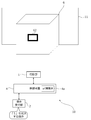
- FIG. 13 is a diagram showing a modified example of the projection of the content image by the projection device 10.
- the projection device 10 may project an image that is uniformly black in the peripheral range 11c other than the content projection range 11a in the projection range 11.
- the control device 4 makes the portion corresponding to the peripheral range 11c in the projected image projected on the projection range 11 black.
- no light is projected from the projection unit 1 onto the peripheral range 11c, and the peripheral range 11c is uniformly black. Therefore, even if there is an object such as a wall behind the projected object 6, the observer can easily recognize the range of the content image 111.
- the projection device 10 does not transmit light to the peripheral range 11c, but may project an image different from the content image 111 on the peripheral range 11c.
- the projection device 10 sets a portion of the projected image projected on the projection range 11 corresponding to the peripheral range 11c as an image of a uniform color (for example, gray) or a fixed pattern (for example, a fine lattice pattern). It may be an image.
- a uniform color for example, gray
- a fixed pattern for example, a fine lattice pattern
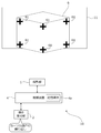
- ⁇ Range setting for deformation example 1 of the projected object 6 by the projection device 10> 14 and 15 are diagrams showing an example of range setting for the modified example 1 of the projected object 6 by the projection device 10.
- the projected object 6 is a rectangular parallelepiped
- the shape of the projected object 6 is not limited to this.
- the projected object 6 may be a cylindrical object as shown in FIG.
- the side surface (curved surface) of the object to be projected 6 that can be seen from the side of the projection device 10 is used as the projection surface
- the user sets the shape of the side surface (for example, the side surface of a cylinder) for the projection device 10 with respect to the projection device 10.
- the projection device 10 first projects the number image 51 and projects the cursor 61 based on the result of receiving the designation of the number from the user.
- the user arranges the cursor 61 so as to surround the desired projection surface on the projected object 6 by performing the above-mentioned various cursor operations on the operation receiving unit 2.
- ten cursors 61 are used to enclose the entire range of the projected object 6 that can be seen from the side of the projection device 10.
- the projection device 10 sets the range surrounded by the cursor 61 as the content projection range 11a.
- the projection device 10 sets the content projection range 11a, which is a curved surface, by using linear interpolation based on each position of the plurality of cursors 61.
- the projection device 10 generates the content image 111 in accordance with the content projection range 11a, and projects the generated content image 111 onto the content projection range 11a.
- the projection device 10 may perform distortion correction according to the curved surface of the content projection range 11a according to the user operation.
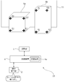
- ⁇ Range setting for deformation example 2 of the projected object 6 by the projection device 10> 16 and 17 are diagrams showing an example of range setting for the second modification of the projected object 6 by the projection device 10.
- the projected object 6 is a rectangular parallelepiped, and two surfaces of the projected object 6 face the projection device 10, and these two surfaces may be used as projection surfaces.
- the user sets the shape of this side surface (for example, two adjacent faces of a rectangular parallelepiped) with respect to the projection device 10.
- the projection device 10 first projects the number image 51 and projects the cursor 61 based on the result of receiving the designation of the number from the user.
- the user arranges the cursor 61 so as to surround the desired projection surface on the projected object 6 by performing the above-mentioned various cursor operations on the operation receiving unit 2.
- six cursors 61 are used to enclose a range of the projected object 6 including two surfaces that can be seen from the side of the projection device 10.
- the projection device 10 sets the range surrounded by the cursor 61 as the content projection range 11a. Then, the projection device 10 generates the content image 111 in accordance with the content projection range 11a, and projects the generated content image 111 onto the content projection range 11a. When the content image 111 is generated, the projection device 10 may perform distortion correction according to the angle of each of the two surfaces included in the content projection range 11a according to the user operation.
- FIG. 18 is a diagram showing another example of range setting for the modified example 2 of the projected object 6 by the projection device 10.
- the projection device 10 sets the content projection ranges 11a and 11b for projecting the two content images 111 based on the respective positions of the cursor 61. You may.
- the content projection ranges 11a and 11b are two surfaces of the projected object 6 facing the projection device 10.
- the projection device 10 generates two content images 111 according to the content projection ranges 11a and 11b, and projects the generated two content images 111 onto the content projection ranges 11a and 11b, respectively.
- the two content images 111 may be each image obtained by dividing the image of one content image into two, or may be content images independent of each other.
- the projection device 10 can instruct a plurality of first ranges (for example, content projection ranges 11a and 11b) by the cursor 61, and different images may be projected as content images on the plurality of first ranges. ..
- the two content images 111 projected on the content projection ranges 11a and 11b may be the same content image.
- the projection device 10 may perform distortion correction according to the angle of each of the two surfaces of the content projection ranges 11a and 11b according to the user operation when generating the two content images 111.
- FIG. 16 which of FIG. 17 and FIG. 18 is the setting result of the content projection range when the user performs the confirmation operation may be set according to the user operation. ..
- the setting result shown in FIG. 17 and the setting result shown in FIG. 18 may be switched according to the user operation.
- the content image 111 may be projected on a plurality of projected objects.
- the projection device 10 may perform projection on one surface of each of the objects to be projected 6a and 6b.
- the projected objects 6a and 6b are rectangular parallelepipeds having different shapes from each other.
- the user sets the shape of the side surface of the projection device 10 (for example, one side of each of the two rectangular parallelepipeds) with respect to the projection device 10.
- the projection device 10 first projects the number image 51 and projects the cursor 61 based on the result of receiving the designation of the number from the user.
- the user arranges the cursor 61 so as to surround the desired projection plane on the projected objects 6a and 6b by performing the above-mentioned various cursor operations on the operation receiving unit 2.
- eight cursors 61 are used to enclose one surface of each of the projected objects 6a and 6b.
- the projection device 10 sets each range surrounded by the cursor 61 as the content projection ranges 11a and 11b. Then, the projection device 10 generates two content images 111 according to the content projection ranges 11a and 11b, and projects the generated two content images 111 onto the content projection ranges 11a and 11b, respectively. When the content image 111 is generated, the projection device 10 may perform distortion correction according to the angle of each of the two surfaces of the content projection ranges 11a and 11b according to the user operation.
- ⁇ Modification example of the first image for the user to indicate the content projection range> 21 and 22 are diagrams showing a modified example of the first image for the user to indicate the content projection range.
- the cursor 61 has been described as an example as the first image for the user to indicate the content projection range, the first image is not limited to the cursor 61.
- the first image may be the frame image 62 shown in FIG.
- the projection device 10 moves to a predetermined position (for example, the center) within the range of "5" of the numerical image 51.
- the frame image 62 is projected onto the image.
- the frame image 62 is an image that can be moved, enlarged, enlarged / reduced, deformed, and the like by user operation.
- the user adjusts the frame image 62 to the four sides of the projection surface of the projected object 6 by performing the operation of the frame image 62 on the operation receiving unit 2.
- the projection device 10 sets the rectangular range surrounded by the frame image 62 as the content projection range 11a.
- the projection surface of the object to be projected 6 is set as the content projection range 11a, as in the example of FIG.
- the operation reception unit 2 may be able to perform a duplication operation for duplicating the frame image 62 so that a plurality of content projection ranges (for example, content projection ranges 11a and 11b) can be set.
- the projection device 10 positions the first image for the user to indicate the first range for projecting the content image at a position corresponding to the user operation (for example, the operation of selecting a number based on the numerical image 51). It is projected from the projection unit 1 so as to overlap the projected image, and the first range is set according to the user operation on the first image. This prevents the first image for the user to indicate the first range on which the content image is projected to be projected at a position different from the projected object, which makes it difficult for the user to find the first image. be able to. Therefore, it is possible to easily set the range for projecting the content image.
- the second image divided into a plurality of ranges a numerical image 51 in which an identifier such as a number is attached to each range has been described as an example, but the second image is not limited to this.
- the second image may be an image that is divided into a plurality of ranges and has no identifier.
- the projection device 10 highlights one of the plurality of ranges of the second image and instructs the user to switch the highlighted range, and the highlighted range is the numerical image 51. Accepts a user operation instructing to select as the initial projection range.
- the initial projection range of the numerical image 51 can be set even if there is no identifier.
- the first image for the user to indicate the first range for projecting the content image is projected from the projection unit 1 at a position other than the end portion of the projection range 11 so as to overlap the projected image. Let me.
- FIG. 23 is a flowchart showing an example of the content image projection process by the control device 4 of the second embodiment.
- the control device 4 executes, for example, the projection process shown in FIG. 23.
- the control device 4 starts the projection process shown in FIG. 23, triggered by the above setting start operation.
- the projection range 11 of the projection device 10 is adjusted to include the projection surface of the object to be projected 6, as in the examples of FIGS. 5 to 10.
- control device 4 controls the projection unit 1 to project the cursor 61 at the center of the projection range 11 (step S231). In this case, the control device 4 does not have to perform the process of projecting the above-mentioned numerical image 51.
- Steps S232 to S237 shown in FIG. 23 are the same as steps S1206 to S1211 shown in FIG.
- the projection device 10 projects the cursor 61 (first image) for the user to indicate the content projection range 11a for projecting the content image 111 to the center of the projection range 11.
- the cursor 61 is projected to a position other than the projection surface of the projection object 6 by roughly aligning the center of the projection range 11 and the center of the projection surface of the projection object 6.
- the projection position of the cursor 61 is not limited to the center of the projection range 11, but may be a predetermined position other than the center of the projection range 11 (for example, a position slightly below the center of the projection range 11). can.
- the above processor A first image for the user to indicate the first range is projected from the projection unit at a position corresponding to the user operation so as to overlap the projected image.
- a control for setting the first range is executed according to a user operation on the first image. Control method.
- the second image is a projection image in which each of the plurality of ranges includes an identifier for the user to select the range. Control method.
- the control method according to (2) or (3) The second image is a projected image divided according to the user operation. Control method.
- the second image is a projection image divided according to the size of the projection range. Control method.
- the control method according to any one of (2) to (5) is a projection image divided according to the shape of the projection range. Control method.
- the control method according to any one of (2) to (6).
- the processor executes control to project the second image from the projection unit in a range selected by the user operation in the projection range. Control method.
- the control method according to any one of (1) to (7).
- the first image includes a cursor that moves within the projected image in response to a user operation. Control method.
- the cursor is a cursor that can be duplicated in the projected image according to a user operation. Control method.
- control method according to any one of (1) to (9).
- a plurality of first ranges can be specified by the first image.
- the processor executes control for projecting different images as the content images on the plurality of first ranges. Control method.
- the control method according to any one of (1) to (10).
- the processor executes control that does not project light from the projection unit or projects an image different from the content image on a range of the projection range that is different from the first range. Control method.
- a projection device that includes a projection unit and a processor and projects a content image into a set first range of the projection range of the projection unit.
- the above processor A first image for the user to indicate the first range is projected from the projection unit at a position corresponding to the user operation so as to overlap the projected image.
- a control for setting the first range is executed according to a user operation on the first image. Projection device.
- a control program for a projection device that includes a projection unit and a processor and projects a content image onto a set first range of the projection ranges of the projection unit.
- a first image for the user to indicate the first range is projected from the projection unit at a position corresponding to the user operation so as to overlap the projected image.
- the first range is set according to the user operation for the first image.
- the above processor A first image for the user to indicate the first range is projected from the projection unit at a position other than the end portion so as to overlap the projected image.
- a control for setting the first range is executed according to a user operation on the first image. Control method.
- a projection device that includes a projection unit and a processor and projects a content image into a set first range of the projection range of the projection unit.
- the above processor A first image for the user to indicate the first range is projected from the projection unit at a position other than the end portion so as to overlap the projected image.
- a control for setting the first range is executed according to a user operation on the first image. Projection device.
- a control program for a projection device that includes a projection unit and a processor and projects a content image onto a set first range of the projection ranges of the projection unit.
- a first image for the user to indicate the first range is projected from the projection unit at a position other than the end portion so as to overlap the projected image.
- the first range is set according to the user operation for the first image.
- Projection unit 2 Operation reception unit 2A, 3A Hollow part 2a, 2b, 3a, 3c, 15a Opening 4 Control device 4a Storage medium 6,6a, 6b Projected object 10 Projecting device 11 Projection range 11a, 11b Content projection range 11c Peripheral Range 12
- Optical modulation unit 15 Housing 21
- Light source 22 Optical modulation unit 23
- Projection optical system 24 Control circuit 31
- Third optical system 34 Lens 51 Numerical image 61 Cursor 62 Frame image 101 Main body 102 First member 103 Second member 104
- Projection direction change mechanism 105 Shift mechanism 106
- Optical unit 111 Content image 121 First optical system G1 image
Abstract
Provided are a control method, a projection device, and a control program with which it is possible to facilitate the setting of an area for projection of a content image. A projecting device (10) projects a content image (111) in a first area that is set in a projection area (11) of a projecting unit (1). The projection device (10) also causes a cursor (61), which a user uses to indicate the first area, to be projected from the projecting unit (1) so as to overlap the projected image in a position corresponding to a user operation, and sets the first area in accordance with a user operation with respect to the cursor (61).
Description
本発明は、制御方法、投影装置、及び制御プログラムに関する。
The present invention relates to a control method, a projection device, and a control program.
特許文献1には、円柱面への投影に係る幾何学補正について、投影範囲のうち画像が含まれる画像領域の範囲を角マーカ等でユーザ指定し、画像領域を円柱の対象領域に一致させるように構成された投影装置が記載されている。
In Patent Document 1, regarding the geometric correction related to the projection on the cylindrical surface, the range of the image area including the image in the projection range is specified by the user with a corner marker or the like, and the image area is matched with the target area of the cylinder. The projection device configured in is described.
特許文献2には、互いに角度を持って交わっている2つの面にまたがるように画像を投射する場合に、投射される画像を直線で分割して得られる2つの部分の各々を個別に歪み補正するように構成された画像処理装置が記載されている。
In Patent Document 2, when an image is projected so as to straddle two surfaces intersecting each other at an angle, each of the two parts obtained by dividing the projected image by a straight line is individually distorted. An image processing apparatus configured to do so is described.
本開示の技術に係る1つの実施形態は、コンテンツ画像を投影する範囲の設定を容易化した制御方法、投影装置、及び制御プログラムを提供する。
One embodiment according to the technique of the present disclosure provides a control method, a projection device, and a control program that facilitates setting of a range for projecting a content image.
本開示の技術に係る1つの実施形態の投影方法は、投影部とプロセッサとを含み、上記投影部の投影範囲のうち設定した第1範囲にコンテンツ画像を投影する投影システムの制御方法であって、上記プロセッサが、上記第1範囲をユーザが指示するための第1画像を、ユーザ操作に応じた位置に投影画像に重なるように上記投影部から投影させ、上記第1画像に対するユーザ操作に応じて上記第1範囲を設定する制御を実行するものである。
The projection method of one embodiment according to the technique of the present disclosure is a control method of a projection system including a projection unit and a processor and projecting a content image into a set first range of the projection ranges of the projection unit. , The processor projects a first image for the user to indicate the first range from the projection unit so as to overlap the projected image at a position corresponding to the user operation, and responds to the user operation on the first image. The control for setting the first range is executed.
本開示の技術に係る1つの実施形態の投影装置は、投影部とプロセッサとを含み、上記投影部の投影範囲のうち設定した第1範囲にコンテンツ画像を投影する投影装置であって、上記プロセッサが、上記第1範囲をユーザが指示するための第1画像を、ユーザ操作に応じた位置に投影画像に重なるように上記投影部から投影させ、上記第1画像に対するユーザ操作に応じて上記第1範囲を設定する制御を実行するものである。
The projection device of one embodiment according to the technique of the present disclosure is a projection device including a projection unit and a processor, and projects a content image in a set first range of the projection range of the projection unit. However, the first image for the user to indicate the first range is projected from the projection unit at a position corresponding to the user operation so as to overlap the projected image, and the first image is projected according to the user operation on the first image. It executes the control to set one range.
本開示の技術に係る1つの実施形態の制御プログラムは、投影部とプロセッサとを含み、上記投影部の投影範囲のうち設定した第1範囲にコンテンツ画像を投影する投影装置の制御プログラムであって、上記プロセッサに、上記第1範囲をユーザが指示するための第1画像を、ユーザ操作に応じた位置に投影画像に重なるように上記投影部から投影させ、上記第1画像に対するユーザ操作に応じて上記第1範囲を設定する、処理を実行させるためのものである。
The control program of one embodiment according to the technique of the present disclosure is a control program of a projection device including a projection unit and a processor and projecting a content image into a set first range of the projection ranges of the projection unit. The processor is projected from the projection unit so as to overlap the projected image at a position corresponding to the user operation, and the first image for the user instructing the first range is projected from the projection unit in response to the user operation on the first image. The purpose is to execute the process of setting the first range.
本開示の技術に係る1つの実施形態の別の投影方法は、投影部とプロセッサとを含み、上記投影部の投影範囲のうち設定した第1範囲にコンテンツ画像を投影する投影システムの制御方法であって、上記プロセッサが、上記第1範囲をユーザが指示するための第1画像を、端部以外の位置に投影画像に重なるように上記投影部から投影させ、上記第1画像に対するユーザ操作に応じて上記第1範囲を設定する制御を実行するものである。
Another projection method of one embodiment according to the technique of the present disclosure is a control method of a projection system including a projection unit and a processor and projecting a content image into a set first range of the projection ranges of the projection unit. Therefore, the processor projects the first image for the user to indicate the first range from the projection unit so as to overlap the projected image at a position other than the end portion, and the user operates the first image. The control for setting the first range is executed accordingly.
本開示の技術に係る1つの実施形態の別の投影装置は、投影部とプロセッサとを含み、上記投影部の投影範囲のうち設定した第1範囲にコンテンツ画像を投影する投影装置であって、上記プロセッサが、上記第1範囲をユーザが指示するための第1画像を、端部以外の位置に投影画像に重なるように上記投影部から投影させ、上記第1画像に対するユーザ操作に応じて上記第1範囲を設定する制御を実行するものである。
Another projection device of one embodiment according to the technique of the present disclosure is a projection device that includes a projection unit and a processor and projects a content image into a set first range of the projection ranges of the projection unit. The processor projects a first image for the user to indicate the first range from the projection unit so as to overlap the projected image at a position other than the end portion, and responds to the user's operation on the first image. It executes the control to set the first range.
本開示の技術に係る1つの実施形態の別の制御プログラムは、投影部とプロセッサとを含み、上記投影部の投影範囲のうち設定した第1範囲にコンテンツ画像を投影する投影装置の制御プログラムであって、上記プロセッサに、上記第1範囲をユーザが指示するための第1画像を、端部以外の位置に投影画像に重なるように上記投影部から投影させ、上記第1画像に対するユーザ操作に応じて上記第1範囲を設定する、処理を実行させるためのものである。
Another control program of one embodiment according to the technique of the present disclosure is a control program of a projection device that includes a projection unit and a processor and projects a content image in a set first range of the projection ranges of the projection unit. Therefore, the processor is made to project the first image for the user to indicate the first range from the projection unit so as to overlap the projected image at a position other than the end portion, and the user can operate the first image. The purpose is to execute the process of setting the first range accordingly.
本発明によれば、コンテンツ画像を投影する範囲の設定を容易化することのできる制御方法、投影装置、及び制御プログラムを提供することができる。
According to the present invention, it is possible to provide a control method, a projection device, and a control program that can facilitate the setting of a range for projecting a content image.
以下、本発明の実施形態の一例について、図面を参照して説明する。
Hereinafter, an example of the embodiment of the present invention will be described with reference to the drawings.
(実施の形態1)
<実施の形態1の投影装置10の概略構成>
図1は、実施の形態1の投影装置10の概略構成を示す模式図である。 (Embodiment 1)
<Rough configuration of theprojection device 10 of the first embodiment>
FIG. 1 is a schematic view showing a schematic configuration of theprojection device 10 of the first embodiment.
<実施の形態1の投影装置10の概略構成>
図1は、実施の形態1の投影装置10の概略構成を示す模式図である。 (Embodiment 1)
<Rough configuration of the
FIG. 1 is a schematic view showing a schematic configuration of the
投影装置10は、投影部1と、制御装置4と、操作受付部2と、を備える。投影部1は、例えば液晶プロジェクタ又はLCOS(Liquid Crystal On Silicon)を用いたプロジェクタ等によって構成される。以下では、投影部1が液晶プロジェクタであるものとして説明する。
The projection device 10 includes a projection unit 1, a control device 4, and an operation reception unit 2. The projection unit 1 is composed of, for example, a liquid crystal projector, a projector using LCOS (Liquid Crystal On Silicon), or the like. Hereinafter, it is assumed that the projection unit 1 is a liquid crystal projector.
制御装置4は、各種のプロセッサにより構成される制御部と、各部と通信するための通信インタフェース(図示省略)と、ハードディスク、SSD(Solid State Drive)、又はROM(Read Only Memory)等の記憶媒体4aと、を含む装置であり、投影部1を統括制御する。
The control device 4 includes a control unit composed of various processors, a communication interface (not shown) for communicating with each unit, and a storage medium such as a hard disk, SSD (Solid State Drive), or ROM (Read Only Memory). It is a device including 4a, and controls the projection unit 1 in an integrated manner.
制御装置4の制御部の各種のプロセッサとしては、プログラムを実行して各種処理を行う汎用的なプロセッサであるCPU(Central Processing Unit)、FPGA(Field Programmable Gate Array)等の製造後に回路構成を変更可能なプロセッサであるプログラマブルロジックデバイス(Programmable Logic Device:PLD)、又はASIC(Application Specific Integrated Circuit)等の特定の処理を実行させるために専用に設計された回路構成を有するプロセッサである専用電気回路等が含まれる。
As various processors of the control unit of the control device 4, the circuit configuration is changed after manufacturing the CPU (Central Processing Unit), FPGA (Field Programmable Gate Array), etc., which are general-purpose processors that execute programs and perform various processes. A dedicated electric circuit or the like, which is a processor having a circuit configuration specially designed to execute a specific process such as a programmable logic device (PLD) or an ASIC (Application Special Integrated Circuit), which is a possible processor. Is included.
これら各種のプロセッサの構造は、より具体的には、半導体素子等の回路素子を組み合わせた電気回路である。制御装置4の制御部は、各種のプロセッサのうちの1つで構成されてもよいし、同種又は異種の2つ以上のプロセッサの組み合わせ(例えば、複数のFPGAの組み合わせ又はCPUとFPGAの組み合わせ)で構成されてもよい。
More specifically, the structure of these various processors is an electric circuit that combines circuit elements such as semiconductor elements. The control unit of the control device 4 may be composed of one of various processors, or a combination of two or more processors of the same type or different types (for example, a combination of a plurality of FPGAs or a combination of a CPU and an FPGA). It may be composed of.
操作受付部2は、ユーザからの各種の操作を受け付けることにより、ユーザからの指示(ユーザ指示)を検出する。操作受付部2は、制御装置4に設けられたボタン、キー、ジョイスティック等であってもよいし、制御装置4の遠隔操作を行うリモートコントローラからの信号を受け付ける受信部等であってもよい。
The operation reception unit 2 detects an instruction (user instruction) from the user by receiving various operations from the user. The operation receiving unit 2 may be a button, a key, a joystick, or the like provided in the control device 4, or may be a receiving unit or the like that receives a signal from a remote controller that remotely controls the control device 4.
被投影物6は、投影部1によって投影画像が表示される投影面を有する物体である。図1に示す例では、被投影物6は、1面のみが投影装置10の側に向いた直方体であり、この1面が投影面となる。図1における被投影物6の上下左右が、実際の被投影物6の上下左右であるとする。また、図1の例では、被投影物6の背後(図1の奥方向)に平面上の壁がある。
The projected object 6 is an object having a projection surface on which a projected image is displayed by the projection unit 1. In the example shown in FIG. 1, the projected object 6 is a rectangular parallelepiped having only one surface facing the projection device 10, and this one surface is the projection surface. It is assumed that the top, bottom, left, and right of the projected object 6 in FIG. 1 are the top, bottom, left, and right of the actual projected object 6. Further, in the example of FIG. 1, there is a wall on a plane behind the projected object 6 (in the depth direction of FIG. 1).
投影範囲11は、投影部1により投影光が照射される範囲である。図1に示す例では、投影範囲11は矩形である。また、図1に示す例では、投影範囲11は、被投影物6の投影面を含む、被投影物6の投影面より広い範囲になっている。
The projection range 11 is a range in which the projected light is irradiated by the projection unit 1. In the example shown in FIG. 1, the projection range 11 is rectangular. Further, in the example shown in FIG. 1, the projection range 11 is a wider range than the projection surface of the projected object 6 including the projection surface of the projected object 6.
図1に示す例において、投影範囲11のうち、投影装置10がコンテンツ画像を投影するコンテンツ投影範囲をユーザ操作によって設定する場合について説明する。コンテンツ投影範囲は、本発明の第1範囲の一例である。例えば、ユーザは、投影装置10がコンテンツ画像を投影するコンテンツ投影範囲を、被投影物6の投影面の全域に設定したいものとする。この場合に、投影装置10に対して、投影範囲11のうちいずれの範囲が、投影装置10の投影面に投影されるコンテンツ投影範囲であるかを設定することを要する。
In the example shown in FIG. 1, a case where the projection device 10 projects the content projection range of the projection range 11 by user operation will be described. The content projection range is an example of the first range of the present invention. For example, the user wants to set the content projection range on which the projection device 10 projects the content image over the entire projection surface of the projected object 6. In this case, it is necessary to set which range of the projection range 11 is the content projection range projected on the projection surface of the projection device 10 with respect to the projection device 10.
なお、投影部1、制御装置4、及び操作受付部2は、例えば一個の装置により実現される(例えば図3,図4参照)。又は、投影部1、制御装置4、及び操作受付部2は、互いに通信を行うことにより連携する、それぞれ別の装置であってもよい。
The projection unit 1, the control device 4, and the operation reception unit 2 are realized by, for example, one device (see, for example, FIGS. 3 and 4). Alternatively, the projection unit 1, the control device 4, and the operation reception unit 2 may be separate devices that cooperate with each other by communicating with each other.
<図1に示す投影部1の内部構成>
図2は、図1に示す投影部1の内部構成の一例を示す模式図である。 <Internal configuration ofprojection unit 1 shown in FIG. 1>
FIG. 2 is a schematic view showing an example of the internal configuration of theprojection unit 1 shown in FIG.
図2は、図1に示す投影部1の内部構成の一例を示す模式図である。 <Internal configuration of
FIG. 2 is a schematic view showing an example of the internal configuration of the
図2に示すように、投影部1は、光源21と、光変調部22と、投影光学系23と、制御回路24と、を備える。
As shown in FIG. 2, the projection unit 1 includes a light source 21, an optical modulation unit 22, a projection optical system 23, and a control circuit 24.
光源21は、レーザ又はLED(Light Emitting Diode)等の発光素子を含み、例えば白色光を出射する。
The light source 21 includes a light emitting element such as a laser or an LED (Light Emitting Diode), and emits white light, for example.
光変調部22は、光源21から出射されて図示省略の色分離機構によって赤、青、緑の3色に分離された各色光を、画像情報に基づいて変調して各色画像を出射する3つの液晶パネルによって構成される。この3つの液晶パネルにそれぞれ赤、青、緑のフィルタを搭載し、光源21から出射された白色光を、各液晶パネルにて変調して各色画像を出射させてもよい。
The light modulation unit 22 modulates each color light emitted from the light source 21 and separated into three colors of red, blue, and green by a color separation mechanism (not shown) based on image information, and emits each color image. It is composed of a liquid crystal panel. Red, blue, and green filters may be mounted on each of the three liquid crystal panels, and the white light emitted from the light source 21 may be modulated by each liquid crystal panel to emit each color image.
投影光学系23は、光源21及び光変調部22からの光が入射されるものであり、少なくとも1つのレンズを含む、例えばリレー光学系によって構成されている。投影光学系23を通過した光は被投影物6に投影される。
The projection optical system 23 receives light from the light source 21 and the light modulation unit 22, and includes, for example, a relay optical system including at least one lens. The light that has passed through the projection optical system 23 is projected onto the object to be projected 6.
制御回路24は、制御装置4から入力される表示用データに基づいて、光源21、光変調部22、及び投影光学系23を制御することにより、被投影物6にこの表示用データに基づく画像を投影させる。制御回路24に入力される表示用データは、赤表示用データと、青表示用データと、緑表示用データとの3つによって構成される。
The control circuit 24 controls the light source 21, the optical modulation unit 22, and the projection optical system 23 based on the display data input from the control device 4, so that the projected object 6 has an image based on the display data. To project. The display data input to the control circuit 24 is composed of three components: red display data, blue display data, and green display data.
また、制御回路24は、制御装置4から入力される命令に基づいて、投影光学系23を変化させることにより、投影部1の投影範囲11(図1参照)の拡大や縮小を行う。また、制御装置4は、操作受付部2によって受け付けられたユーザからの操作に基づいて投影光学系23を変化させることにより、投影部1の投影範囲11の移動を行ってもよい。
Further, the control circuit 24 expands or contracts the projection range 11 (see FIG. 1) of the projection unit 1 by changing the projection optical system 23 based on the command input from the control device 4. Further, the control device 4 may move the projection range 11 of the projection unit 1 by changing the projection optical system 23 based on the operation from the user received by the operation reception unit 2.
また、投影装置10は、投影光学系23のイメージサークルを維持しつつ、投影範囲11を機械的又は光学的に移動させるシフト機構を備える。投影光学系23のイメージサークルは、投影光学系23に入射した投影光が、光量落ち、色分離、周辺湾曲などの点から適正に投影光学系23を通過する領域である。
Further, the projection device 10 includes a shift mechanism that mechanically or optically moves the projection range 11 while maintaining the image circle of the projection optical system 23. The image circle of the projection optical system 23 is a region in which the projected light incident on the projection optical system 23 appropriately passes through the projection optical system 23 from the points of light loss, color separation, peripheral curvature, and the like.
シフト機構は、光学系シフトを行う光学系シフト機構と、電子シフトを行う電子シフト機構と、の少なくともいずれかにより実現される。
The shift mechanism is realized by at least one of an optical system shift mechanism that shifts the optical system and an electron shift mechanism that performs electron shift.
光学系シフト機構は、例えば、投影光学系23を光軸に垂直な方向に移動させる機構(例えば図3,図4参照)、又は、投影光学系23を移動させる代わりに光変調部22を光軸に垂直な方向に移動させる機構である。また、光学系シフト機構は、投影光学系23の移動と光変調部22の移動とを組み合わせて行うものであってもよい。
The optical system shift mechanism is, for example, a mechanism for moving the projection optical system 23 in a direction perpendicular to the optical axis (see, for example, FIGS. 3 and 4), or an optical modulation unit 22 instead of moving the projection optical system 23. It is a mechanism that moves in the direction perpendicular to the axis. Further, the optical system shift mechanism may be a combination of the movement of the projection optical system 23 and the movement of the optical modulation unit 22.
電子シフト機構は、光変調部22において光を透過させる範囲を変化させることによる疑似的な投影範囲11のシフトを行う機構である。
The electronic shift mechanism is a mechanism that shifts the pseudo projection range 11 by changing the range through which light is transmitted in the optical modulation unit 22.
また、投影装置10は、投影光学系23のイメージサークルとともに投影範囲11を移動させる投影方向変更機構を備えてもよい。投影方向変更機構は、機械的な回転で投影部1の向きを変更することにより、投影部1の投影方向を変化させる機構である(例えば図3,図4参照)。
Further, the projection device 10 may include a projection direction changing mechanism that moves the projection range 11 together with the image circle of the projection optical system 23. The projection direction changing mechanism is a mechanism that changes the projection direction of the projection unit 1 by changing the direction of the projection unit 1 by mechanical rotation (see, for example, FIGS. 3 and 4).
<投影装置10の機械的構成>
図3は、投影装置10の外観構成を示す模式図である。図4は、図3に示す投影装置10の光学ユニット106の断面模式図である。図4は、図3に示す本体部101から出射される光の光路に沿った面での断面を示している。 <Mechanical configuration ofprojection device 10>
FIG. 3 is a schematic view showing an external configuration of theprojection device 10. FIG. 4 is a schematic cross-sectional view of the optical unit 106 of the projection device 10 shown in FIG. FIG. 4 shows a cross section of the light emitted from the main body 101 shown in FIG. 3 along the optical path.
図3は、投影装置10の外観構成を示す模式図である。図4は、図3に示す投影装置10の光学ユニット106の断面模式図である。図4は、図3に示す本体部101から出射される光の光路に沿った面での断面を示している。 <Mechanical configuration of
FIG. 3 is a schematic view showing an external configuration of the
図3に示すように、投影装置10は、本体部101と、本体部101から突出して設けられた光学ユニット106と、を備える。図3に示す構成において、操作受付部2と、制御装置4と、投影部1における光源21、光変調部22、及び制御回路24と、は本体部101に設けられる。投影部1における投影光学系23は光学ユニット106に設けられる。
As shown in FIG. 3, the projection device 10 includes a main body portion 101 and an optical unit 106 provided so as to project from the main body portion 101. In the configuration shown in FIG. 3, the operation reception unit 2, the control device 4, the light source 21, the light modulation unit 22, and the control circuit 24 in the projection unit 1 are provided in the main body 101. The projection optical system 23 in the projection unit 1 is provided in the optical unit 106.
光学ユニット106は、本体部101に支持される第一部材102と、第一部材102に支持された第二部材103と、を備える。
The optical unit 106 includes a first member 102 supported by the main body 101 and a second member 103 supported by the first member 102.
なお、第一部材102と第二部材103は一体化された部材であってもよい。光学ユニット106は、本体部101に着脱自在に構成(換言すると交換可能に構成)されていてもよい。
The first member 102 and the second member 103 may be integrated members. The optical unit 106 may be detachably configured (in other words, interchangeable) on the main body 101.
本体部101は、光学ユニット106と連結される部分に光を通すための開口15a(図4参照)が形成された筐体15(図4参照)を有する。
The main body 101 has a housing 15 (see FIG. 4) in which an opening 15a (see FIG. 4) for passing light is formed in a portion connected to the optical unit 106.
本体部101の筐体15の内部には、図3に示すように、光源21と、光源21から出射される光を入力画像データに基づいて空間変調して画像を生成する光変調部22(図2参照)を含む光変調ユニット12と、が設けられている。
Inside the housing 15 of the main body 101, as shown in FIG. 3, a light source 21 and an optical modulation unit 22 (a light modulation unit 22 that spatially modulates the light emitted from the light source 21 based on input image data to generate an image). An optical modulation unit 12 including (see FIG. 2) is provided.
光源21から出射された光は、光変調ユニット12の光変調部22に入射され、光変調部22によって空間変調されて出射される。
The light emitted from the light source 21 is incident on the optical modulation unit 22 of the optical modulation unit 12, and is spatially modulated by the optical modulation unit 22 and emitted.
図4に示すように、光変調ユニット12によって空間変調された光によって形成される画像は、筐体15の開口15aを通過して光学ユニット106に入射され、投影対象物としての被投影物6に投影されて、画像G1が観察者から視認可能となる。
As shown in FIG. 4, the image formed by the light spatially modulated by the light modulation unit 12 passes through the opening 15a of the housing 15 and is incident on the optical unit 106, and the projected object 6 as a projection object 6 The image G1 becomes visible to the observer.
図4に示すように、光学ユニット106は、本体部101の内部と繋がる中空部2Aを有する第一部材102と、中空部2Aと繋がる中空部3Aを有する第二部材103と、中空部2Aに配置された第一光学系121及び反射部材122と、中空部3Aに配置された第二光学系31、反射部材32、第三光学系33、及びレンズ34と、シフト機構105と、投影方向変更機構104と、を備える。
As shown in FIG. 4, the optical unit 106 includes a first member 102 having a hollow portion 2A connected to the inside of the main body 101, a second member 103 having a hollow portion 3A connected to the hollow portion 2A, and a hollow portion 2A. The first optical system 121 and the reflecting member 122 arranged, the second optical system 31, the reflecting member 32, the third optical system 33, and the lens 34 arranged in the hollow portion 3A, the shift mechanism 105, and the projection direction change. The mechanism 104 is provided.
第一部材102は、断面外形が一例として矩形の部材であり、開口2aと開口2bが互いに垂直な面に形成されている。第一部材102は、本体部101の開口15aと対面する位置に開口2aが配置される状態にて、本体部101によって支持されている。本体部101の光変調ユニット12の光変調部22から射出された光は、開口15a及び開口2aを通って第一部材102の中空部2Aに入射される。
The first member 102 is a member having a rectangular cross-sectional outer shape as an example, and the openings 2a and 2b are formed on surfaces perpendicular to each other. The first member 102 is supported by the main body 101 in a state where the opening 2a is arranged at a position facing the opening 15a of the main body 101. The light emitted from the light modulation unit 22 of the light modulation unit 12 of the main body 101 passes through the openings 15a and 2a and is incident on the hollow portion 2A of the first member 102.
本体部101から中空部2Aに入射される光の入射方向を方向X1と記載し、方向X1の逆方向を方向X2と記載し、方向X1と方向X2を総称して方向Xと記載する。また、図4において、紙面手前から奥に向かう方向とその逆方向を方向Zと記載する。方向Zのうち、紙面手前から奥に向かう方向を方向Z1と記載し、紙面奥から手前に向かう方向を方向Z2と記載する。
The incident direction of the light incident on the hollow portion 2A from the main body portion 101 is described as the direction X1, the opposite direction of the direction X1 is described as the direction X2, and the direction X1 and the direction X2 are collectively referred to as the direction X. Further, in FIG. 4, the direction from the front to the back of the paper and the opposite direction are described as the direction Z. Of the directions Z, the direction from the front to the back of the paper is described as the direction Z1, and the direction from the back to the front of the paper is described as the direction Z2.
また、方向X及び方向Zに垂直な方向を方向Yと記載し、方向Yのうち、図4において上に向かう方向を方向Y1と記載し、図4において下に向かう方向を方向Y2と記載する。図4の例では方向Y2が鉛直方向となるように投影装置10が配置されている。
Further, the direction perpendicular to the direction X and the direction Z is described as the direction Y, and among the directions Y, the upward direction in FIG. 4 is described as the direction Y1, and the downward direction in FIG. 4 is described as the direction Y2. .. In the example of FIG. 4, the projection device 10 is arranged so that the direction Y2 is the vertical direction.
図2に示した投影光学系23は、第一光学系121、反射部材122、第二光学系31、反射部材32、第三光学系33、及びレンズ34により構成される。図4には、この投影光学系23の光軸Kが示されている。第一光学系121、反射部材122、第二光学系31、反射部材32、第三光学系33、及びレンズ34は、光変調部22側からこの順に光軸Kに沿って配置されている。
The projection optical system 23 shown in FIG. 2 is composed of a first optical system 121, a reflection member 122, a second optical system 31, a reflection member 32, a third optical system 33, and a lens 34. FIG. 4 shows the optical axis K of the projection optical system 23. The first optical system 121, the reflective member 122, the second optical system 31, the reflective member 32, the third optical system 33, and the lens 34 are arranged along the optical axis K in this order from the optical modulation unit 22 side.
第一光学系121は、少なくとも1つのレンズを含み、本体部101から第一部材102に入射された方向X1に進む光を反射部材122に導く。
The first optical system 121 includes at least one lens, and guides light traveling from the main body 101 to the first member 102 in the direction X1 to the reflecting member 122.
反射部材122は、第一光学系121から入射された光を方向Y1に反射させる。反射部材122は、例えばミラー等によって構成される。第一部材102には、反射部材122にて反射した光の光路上に開口2bが形成されており、この反射した光は開口2bを通過して第二部材103の中空部3Aへと進む。
The reflecting member 122 reflects the light incident from the first optical system 121 in the direction Y1. The reflective member 122 is composed of, for example, a mirror or the like. The first member 102 has an opening 2b formed on the optical path of the light reflected by the reflecting member 122, and the reflected light passes through the opening 2b and proceeds to the hollow portion 3A of the second member 103.
第二部材103は、断面外形が略T字状の部材であり、第一部材102の開口2bと対面する位置に開口3aが形成されている。第一部材102の開口2bを通過した本体部101からの光は、この開口3aを通って第二部材103の中空部3Aに入射される。なお、第一部材102や第二部材103の断面外形は任意であり、上記のものには限定されない。
The second member 103 is a member having a substantially T-shaped cross section, and an opening 3a is formed at a position facing the opening 2b of the first member 102. The light from the main body 101 that has passed through the opening 2b of the first member 102 is incident on the hollow portion 3A of the second member 103 through the opening 3a. The cross-sectional outer shape of the first member 102 and the second member 103 is arbitrary, and is not limited to the above.
第二光学系31は、少なくとも1つのレンズを含み、第一部材102から入射された光を、反射部材32に導く。
The second optical system 31 includes at least one lens, and guides the light incident from the first member 102 to the reflecting member 32.
反射部材32は、第二光学系31から入射される光を方向X2に反射させて第三光学系33に導く。反射部材32は、例えばミラー等によって構成される。
The reflecting member 32 reflects the light incident from the second optical system 31 in the direction X2 and guides it to the third optical system 33. The reflective member 32 is composed of, for example, a mirror or the like.
第三光学系33は、少なくとも1つのレンズを含み、反射部材32にて反射された光をレンズ34に導く。
The third optical system 33 includes at least one lens, and guides the light reflected by the reflecting member 32 to the lens 34.
レンズ34は、第二部材103の方向X2側の端部に形成された開口3cを塞ぐ形でこの端部に配置されている。レンズ34は、第三光学系33から入射された光を被投影物6に投影する。
The lens 34 is arranged at this end so as to close the opening 3c formed at the end of the second member 103 on the direction X2 side. The lens 34 projects the light incident from the third optical system 33 onto the projected object 6.
投影方向変更機構104は、第一部材102に対して第二部材103を回転自在に連結する回転機構である。この投影方向変更機構104によって、第二部材103は、方向Yに延びる回転軸(具体的には光軸K)の回りに回転自在に構成されている。なお、投影方向変更機構104は、光学系を回転させることができればよく、図4に示した配置位置に限定されない。また、回転機構の数も1つに限らず、複数設けられていてもよい。
The projection direction changing mechanism 104 is a rotation mechanism that rotatably connects the second member 103 to the first member 102. By the projection direction changing mechanism 104, the second member 103 is rotatably configured around a rotation axis (specifically, an optical axis K) extending in the direction Y. The projection direction changing mechanism 104 is not limited to the arrangement position shown in FIG. 4, as long as the optical system can be rotated. Further, the number of rotation mechanisms is not limited to one, and a plurality of rotation mechanisms may be provided.
シフト機構105は、投影光学系の光軸K(換言すると光学ユニット106)をその光軸Kに垂直な方向(図4の方向Y)に移動させるための機構である。具体的には、シフト機構105は、第一部材102の本体部101に対する方向Yの位置を変更することができるように構成されている。シフト機構105は、手動にて第一部材102を移動させるものの他、電動にて第一部材102を移動させるものであってもよい。
The shift mechanism 105 is a mechanism for moving the optical axis K (in other words, the optical unit 106) of the projection optical system in the direction perpendicular to the optical axis K (direction Y in FIG. 4). Specifically, the shift mechanism 105 is configured so that the position of the first member 102 in the direction Y with respect to the main body 101 can be changed. The shift mechanism 105 may be one in which the first member 102 is manually moved, or one in which the first member 102 is electrically moved.
図4は、シフト機構105によって第一部材102が方向Y1側に最大限移動された状態を示している。この図4に示す状態から、シフト機構105によって第一部材102が方向Y2に移動することで、光変調部22によって形成される画像の中心(換言すると表示面の中心)と光軸Kとの相対位置が変化して、被投影物6に投影されている画像G1を方向Y2にシフト(平行移動)させることができる。
FIG. 4 shows a state in which the first member 102 is moved to the direction Y1 side as much as possible by the shift mechanism 105. From the state shown in FIG. 4, the first member 102 is moved in the direction Y2 by the shift mechanism 105, so that the center of the image (in other words, the center of the display surface) formed by the optical modulation unit 22 and the optical axis K are aligned with each other. The relative position changes, and the image G1 projected on the projected object 6 can be shifted (translated) in the direction Y2.
なお、シフト機構105は、光学ユニット106を方向Yに移動させる代わりに、光変調部22を方向Yに移動させる機構であってもよい。この場合でも、被投影物6に投影されている画像G1を方向Y2に移動させることができる。
The shift mechanism 105 may be a mechanism that moves the optical modulation unit 22 in the direction Y instead of moving the optical unit 106 in the direction Y. Even in this case, the image G1 projected on the projected object 6 can be moved in the direction Y2.
<投影装置10によるコンテンツ画像の投影手順>
図5~図11は、投影装置10によるコンテンツ画像の投影手順の一例を示す図である。ここでは、投影装置10の位置の調整や投影装置10の投影光学系23の画角調整により、図1の例と同様に、投影装置10の投影範囲11が被投影物6の投影面を含むように調整されているものとする。 <Procedure for projecting content image byprojection device 10>
5 to 11 are diagrams showing an example of a procedure for projecting a content image by theprojection device 10. Here, by adjusting the position of the projection device 10 and adjusting the angle of view of the projection optical system 23 of the projection device 10, the projection range 11 of the projection device 10 includes the projection surface of the projected object 6 as in the example of FIG. It shall be adjusted so as to.
図5~図11は、投影装置10によるコンテンツ画像の投影手順の一例を示す図である。ここでは、投影装置10の位置の調整や投影装置10の投影光学系23の画角調整により、図1の例と同様に、投影装置10の投影範囲11が被投影物6の投影面を含むように調整されているものとする。 <Procedure for projecting content image by
5 to 11 are diagrams showing an example of a procedure for projecting a content image by the
図5に示すように、まず、投影装置10は、コンテンツ投影範囲の設定開始を指示する設定開始操作を操作受付部2から受け付けると、数字画像51を投影範囲11に投影する。数字画像51は、複数の範囲に区切られた第2画像の一例である。
As shown in FIG. 5, first, when the projection device 10 receives the setting start operation instructing the start of setting the content projection range from the operation reception unit 2, the projection device 10 projects the numerical image 51 onto the projection range 11. The numerical image 51 is an example of a second image divided into a plurality of ranges.
図5の例において、数字画像51は、3×3のマトリクス状に、9つの範囲に区切られている。また、数字画像51においては、区切られた複数の範囲のそれぞれに、その範囲をユーザが選択するための識別子が含まれている。図5の例では、数字画像51は、9つの範囲のそれぞれに「1」~「9」の数字が含まれた画像である。
In the example of FIG. 5, the numerical image 51 is divided into nine ranges in a 3 × 3 matrix. Further, in the numerical image 51, each of the plurality of divided ranges includes an identifier for the user to select the range. In the example of FIG. 5, the number image 51 is an image in which the numbers “1” to “9” are included in each of the nine ranges.
なお、数字画像51において、「1」~「9」の数字の並びは任意である。また、数字画像51の分割数は、9に限らず、2以上の任意の数とすることができる。また、数字画像51の分割形状は、マトリクス状に限らず、他の分割形状としてもよい。また、識別子は、「1」~「9」のような数字に限らず、「A」~「I」のようなアルファベット等、互いに重複しない各種の識別子とすることができる。
In the number image 51, the arrangement of the numbers "1" to "9" is arbitrary. Further, the number of divisions of the numerical image 51 is not limited to 9, and can be any number of 2 or more. Further, the divided shape of the numerical image 51 is not limited to the matrix shape, and may be another divided shape. Further, the identifier is not limited to numbers such as "1" to "9", and may be various identifiers that do not overlap with each other, such as alphabets such as "A" to "I".
また、図5の例では、被投影物6は投影範囲11の中央付近に位置しており、その結果、数字画像51の中央にある「5」の範囲の全部と、「5」以外の各範囲の一部と、が被投影物6の投影面に投影されている状態である。
Further, in the example of FIG. 5, the projected object 6 is located near the center of the projection range 11, and as a result, the entire range of “5” in the center of the numerical image 51 and each other than “5”. A part of the range is a state in which is projected on the projection surface of the object to be projected 6.
次に、図6に示すように、投影装置10の調整を行うユーザは、数字画像51を見て、「5」の範囲が被投影物6の投影面の中央付近にあるため、「1」~「9」の中から「5」を選択する操作を操作受付部2に行う。これに対して、投影装置10は、数字画像51の「5」の範囲内の所定位置(例えば中央)にカーソル61を投影する。
Next, as shown in FIG. 6, the user who adjusts the projection device 10 looks at the numerical image 51, and since the range of “5” is near the center of the projection surface of the projected object 6, “1”. -The operation of selecting "5" from "9" is performed on the operation reception unit 2. On the other hand, the projection device 10 projects the cursor 61 at a predetermined position (for example, the center) within the range of "5" of the numerical image 51.
図6の例では、投影装置10は、カーソル61の投影の際に、図5に示した数字画像51を非投影にしているが、数字画像51を投影したままカーソル61を投影してもよいし、数字画像51の一部(例えば「5」の数字)のみを非投影にしてカーソル61を投影してもよい。
In the example of FIG. 6, the projection device 10 does not project the numerical image 51 shown in FIG. 5 when projecting the cursor 61, but the cursor 61 may be projected while the numerical image 51 is projected. Then, the cursor 61 may be projected by non-projecting only a part of the numerical image 51 (for example, the number "5").
カーソル61は、ユーザ操作に応じて投影画像内で移動する画像である。カーソル61の投影は、例えば、投影範囲11に投影する投影画像にカーソル61を含めることにより行うことができる。これにより、カーソル61を投影画像に重なるように投影することができる。図9に示す例では、カーソル61は十字型のカーソルであるが、カーソル61の形状は、これに限らず、例えば四角形や円形などの各種の形状とすることができる。
The cursor 61 is an image that moves in the projected image according to the user operation. The projection of the cursor 61 can be performed, for example, by including the cursor 61 in the projected image projected on the projection range 11. As a result, the cursor 61 can be projected so as to overlap the projected image. In the example shown in FIG. 9, the cursor 61 is a cross-shaped cursor, but the shape of the cursor 61 is not limited to this, and may be various shapes such as a quadrangle and a circle.
このように、投影装置10は、数字画像51のうちユーザ操作によって選択された範囲の位置に、カーソル61を含む投影画像を投影する。これにより、カーソル61が被投影物6以外の位置に投影されてユーザがカーソル61を見つけることが困難になることを回避することができる。
In this way, the projection device 10 projects the projection image including the cursor 61 at the position of the range selected by the user operation in the numerical image 51. As a result, it is possible to prevent the cursor 61 from being projected to a position other than the projected object 6 and making it difficult for the user to find the cursor 61.
特に、被投影物6の背後の壁が被投影物6から離れていたり、被投影物6の背後に壁等の物体がなかったりする場合、カーソル61が被投影物6以外の位置に投影されると、ユーザはカーソル61を視認することが困難になる。これに対して、投影装置10によれば、ユーザは、数字画像51の各数字のうち被投影物6に投影された数字を選択する操作を行うことにより、カーソル61が被投影物6に投影されるため、カーソル61が被投影物6以外の位置に投影されることを回避することができる。
In particular, when the wall behind the projected object 6 is separated from the projected object 6 or there is no object such as a wall behind the projected object 6, the cursor 61 is projected to a position other than the projected object 6. Then, it becomes difficult for the user to visually recognize the cursor 61. On the other hand, according to the projection device 10, the cursor 61 projects onto the projected object 6 by performing an operation of selecting a number projected on the projected object 6 from each of the numbers of the numerical image 51. Therefore, it is possible to prevent the cursor 61 from being projected at a position other than the projected object 6.
次に、図7に示すように、ユーザは、カーソル61を移動させる移動操作を操作受付部2に行う。図7の例では、ユーザは、被投影物6の投影面の左下にカーソル61が移動するように移動操作を行う。これに対して、投影装置10は、受け付けた移動操作に応じた方向及び量でカーソル61を移動させる。カーソル61の移動は、例えば、投影範囲11に投影する投影画像における、カーソル61を含める位置を変更することにより行うことができる。
Next, as shown in FIG. 7, the user performs a movement operation for moving the cursor 61 on the operation reception unit 2. In the example of FIG. 7, the user performs a movement operation so that the cursor 61 moves to the lower left of the projection surface of the projection object 6. On the other hand, the projection device 10 moves the cursor 61 in the direction and amount according to the received movement operation. The movement of the cursor 61 can be performed, for example, by changing the position including the cursor 61 in the projected image projected on the projection range 11.
次に、図8に示すように、ユーザは、カーソル61を複製させる複製操作を操作受付部2に行う。これに対して、投影装置10は、カーソル61を複製する。カーソル61の複製は、例えば、投影範囲11に投影する投影画像に含めるカーソル61を追加することにより行うことができる。
Next, as shown in FIG. 8, the user performs a duplication operation for duplicating the cursor 61 on the operation reception unit 2. On the other hand, the projection device 10 duplicates the cursor 61. The duplication of the cursor 61 can be performed, for example, by adding the cursor 61 to be included in the projected image projected on the projection range 11.
複数のカーソル61が投影されている状態においては、上記の移動操作及び複製操作に応じた処理は、複数のカーソル61のうち選択カーソルとして選択されているカーソル61に対して行われる。ユーザは、複数のカーソル61のうちの選択カーソルを切り替えることを指示する選択カーソル切替操作を操作受付部2に行うことにより、複数のカーソル61のうちの選択カーソルを切り替えることができる。
In a state where a plurality of cursors 61 are projected, the processing corresponding to the above-mentioned movement operation and duplication operation is performed on the cursor 61 selected as the selection cursor among the plurality of cursors 61. The user can switch the selection cursor among the plurality of cursors 61 by performing the selection cursor switching operation instructing the operation reception unit 2 to switch the selection cursor among the plurality of cursors 61.
次に、図9に示すように、ユーザは、上記の移動操作、複製操作、及び選択カーソル切替操作を含むカーソル操作を繰り返し行うことにより、被投影物6の投影面の四隅にカーソル61を配置する。
Next, as shown in FIG. 9, the user repeatedly performs the cursor operation including the above-mentioned movement operation, duplication operation, and selection cursor switching operation, thereby arranging the cursors 61 at the four corners of the projection surface of the projected object 6. do.
次に、図10に示すように、ユーザは、現在のカーソル61によって特定される範囲をコンテンツ投影範囲として確定することを指示する確定操作を操作受付部2に行う。これに対して、投影装置10は、図9において4つのカーソル61が配置されていた各位置を四隅とする矩形の範囲をコンテンツ投影範囲11aとして設定する。なお、図面においてはコンテンツ投影範囲11aを仮想的に太線で図示している。
Next, as shown in FIG. 10, the user performs a confirmation operation instructing the operation reception unit 2 to determine the range specified by the current cursor 61 as the content projection range. On the other hand, the projection device 10 sets a rectangular range having four corners at each position where the four cursors 61 are arranged in FIG. 9 as the content projection range 11a. In the drawing, the content projection range 11a is virtually shown by a thick line.
次に、図11に示すように、ユーザは、コンテンツ投影範囲11aへのコンテンツ画像の投影開始を指示するコンテンツ投影操作を操作受付部2に行う。これに対して、投影装置10は、設定したコンテンツ投影範囲11aに合わせたコンテンツ画像111を生成し、生成したコンテンツ画像111のコンテンツ投影範囲11aへの投影を開始する。
Next, as shown in FIG. 11, the user performs a content projection operation instructing the operation reception unit 2 to start projecting the content image onto the content projection range 11a. On the other hand, the projection device 10 generates a content image 111 that matches the set content projection range 11a, and starts projecting the generated content image 111 onto the content projection range 11a.
図11に示す例では、コンテンツ画像111は、多数の魚が泳いでいる様子を示す動画像である。ただし、コンテンツ画像111は、これに限らず、任意の静止画像又は動画像とすることができる。
In the example shown in FIG. 11, the content image 111 is a moving image showing a state in which a large number of fish are swimming. However, the content image 111 is not limited to this, and may be any still image or moving image.
<制御装置4によるコンテンツ画像の投影処理>
図12は、制御装置4によるコンテンツ画像の投影処理の一例を示すフローチャートである。制御装置4は、例えば図12に示す投影処理を実行する。例えば、制御装置4は、上記の設定開始操作を契機として図12に示す投影処理を開始する。ここでは、図5~図10の例と同様に、投影装置10の投影範囲11が被投影物6の投影面を含むように調整されているものとする。 <Projection processing of content image bycontrol device 4>
FIG. 12 is a flowchart showing an example of the content image projection process by thecontrol device 4. The control device 4 executes, for example, the projection process shown in FIG. For example, the control device 4 starts the projection process shown in FIG. 12 triggered by the above setting start operation. Here, it is assumed that the projection range 11 of the projection device 10 is adjusted to include the projection surface of the object to be projected 6, as in the examples of FIGS. 5 to 10.
図12は、制御装置4によるコンテンツ画像の投影処理の一例を示すフローチャートである。制御装置4は、例えば図12に示す投影処理を実行する。例えば、制御装置4は、上記の設定開始操作を契機として図12に示す投影処理を開始する。ここでは、図5~図10の例と同様に、投影装置10の投影範囲11が被投影物6の投影面を含むように調整されているものとする。 <Projection processing of content image by
FIG. 12 is a flowchart showing an example of the content image projection process by the
まず、制御装置4は、投影範囲11のうち、数字画像51(第2画像)を投影する範囲を設定する(ステップS1201)。例えば、制御装置4は、投影部1が投影範囲11の全範囲を、数字画像51を投影する範囲として設定する。
First, the control device 4 sets a range in which the numerical image 51 (second image) is projected out of the projection range 11 (step S1201). For example, the control device 4 sets the entire range of the projection range 11 as the range in which the projection unit 1 projects the numerical image 51.
又は、制御装置4は、ユーザ操作等に応じて、投影範囲11の一部の範囲を、数字画像51を投影する範囲として設定してもよい。例えば、制御装置4は、投影範囲11のうち、上半分、下半分、右半分、左半分などの一部の範囲の指定を操作受付部2から受け付け、受け付けた範囲を、数字画像51を投影する範囲として設定してもよい。
Alternatively, the control device 4 may set a part of the projection range 11 as a range for projecting the numerical image 51 according to a user operation or the like. For example, the control device 4 receives the designation of a part of the projection range 11 such as the upper half, the lower half, the right half, and the left half from the operation reception unit 2, and projects the received range with the numerical image 51. It may be set as a range to be used.
このように、投影範囲11のうちユーザ操作によって選択された範囲に、数字画像51を投影することにより、投影範囲11における被投影物6の投影面のおよその位置をユーザが把握している場合に、範囲を限定して数字画像51を投影し、カーソル61の初期の表示位置を効率よく設定することができる。
In this way, when the user grasps the approximate position of the projection surface of the projected object 6 in the projection range 11 by projecting the numerical image 51 into the range selected by the user operation in the projection range 11. The numerical image 51 can be projected in a limited range, and the initial display position of the cursor 61 can be efficiently set.
次に、制御装置4は、数字画像51を生成する(ステップS1202)。すなわち、制御装置4は、数字画像51の形状、数字画像51の範囲の分割数、数字画像51の各範囲に付す識別子等を設定する。例えば、制御装置4のメモリには数字画像51の情報が予め記憶されており、制御装置4はこの情報を読み出すことにより数字画像51を生成する。
Next, the control device 4 generates the numerical image 51 (step S1202). That is, the control device 4 sets the shape of the number image 51, the number of divisions of the range of the number image 51, the identifier attached to each range of the number image 51, and the like. For example, the information of the numerical image 51 is stored in the memory of the control device 4 in advance, and the control device 4 generates the numerical image 51 by reading this information.
又は、制御装置4は、ユーザ操作に応じて区切られた数字画像51を生成してもよい。例えば、投影装置10は、数字画像51の最大数字、又は数字画像51における範囲の分割数の設定を操作受付部2から受け付けることにより、数字画像51を生成する。これにより、様々な大きさや形状の被投影物6の投影面に対して柔軟に、ユーザ操作に応じて区切られた数字画像51を生成することができる。
Alternatively, the control device 4 may generate a numerical image 51 divided according to the user operation. For example, the projection device 10 generates the numerical image 51 by receiving the setting of the maximum number of the numerical image 51 or the number of divisions of the range in the numerical image 51 from the operation reception unit 2. As a result, it is possible to flexibly generate a numerical image 51 divided according to the user operation with respect to the projection surface of the object 6 having various sizes and shapes.
又は、制御装置4は、投影範囲11の大きさに基づいて区切られた数字画像51を生成してもよい。例えば、制御装置4は、投影範囲11が大きいほど、多くの範囲に区切られた数字画像51を生成する。これにより、例えば投影範囲11が大きい場合は多くの範囲に区切られた数字画像51を投影できるため、数字画像51の各範囲が大きくなり過ぎてカーソル61を投影させる範囲の指定が困難になることを回避することができる。
Alternatively, the control device 4 may generate a numerical image 51 divided based on the size of the projection range 11. For example, the control device 4 generates a numerical image 51 divided into many ranges as the projection range 11 becomes larger. As a result, for example, when the projection range 11 is large, the numerical image 51 divided into many ranges can be projected, so that each range of the numerical image 51 becomes too large and it becomes difficult to specify the range on which the cursor 61 is projected. Can be avoided.
又は、制御装置4は、投影範囲11の形状に基づいて区切られた数字画像51を生成してもよい。例えば、制御装置4は、投影範囲11が縦長の矩形である場合は縦方向の分割数を横方向の分割数より多く(すなわち横方向の区切り線を縦方向の区切り線より多く)した数字画像51を生成する。また、制御装置4は、投影範囲11が横長の矩形である場合は横方向の分割数を縦方向の分割数より多くした数字画像51を生成する。これにより、例えば投影範囲11が縦長の矩形である場合は縦方向に多くの範囲に区切られた数字画像51を投影できるため、数字画像51の各範囲の縦方向に大きくなり過ぎてカーソル61を投影させる範囲の指定が困難になることを回避することができる。
Alternatively, the control device 4 may generate a numerical image 51 divided based on the shape of the projection range 11. For example, in the control device 4, when the projection range 11 is a vertically long rectangular shape, the number of divisions in the vertical direction is larger than the number of divisions in the horizontal direction (that is, the number of division lines in the horizontal direction is larger than the number of division lines in the vertical direction). 51 is generated. Further, when the projection range 11 is a horizontally long rectangle, the control device 4 generates a numerical image 51 in which the number of divisions in the horizontal direction is larger than the number of divisions in the vertical direction. As a result, for example, when the projection range 11 is a vertically long rectangle, the numerical image 51 divided into many ranges in the vertical direction can be projected, so that the cursor 61 becomes too large in the vertical direction of each range of the numerical image 51. It is possible to avoid difficulty in specifying the projection range.
次に、制御装置4は、投影部1を制御して、ステップS1201によって決定された範囲に、ステップS1202によって生成した数字画像51を投影させる(ステップS1203)。次に、制御装置4は、ステップS1203によって投影させた数字画像51に含まれる数字の中からユーザが選択した数字を、操作受付部2から受け付ける(ステップS1204)。次に、制御装置4は、投影部1を制御して、数字画像51の各範囲のうち、ステップS1204によって受け付けた数字に対応する範囲にカーソル61(第1画像)を投影させる(ステップS1205)。
Next, the control device 4 controls the projection unit 1 to project the numerical image 51 generated in step S1202 into the range determined in step S1201 (step S1203). Next, the control device 4 receives the number selected by the user from the numbers included in the number image 51 projected in step S1203 from the operation reception unit 2 (step S1204). Next, the control device 4 controls the projection unit 1 to project the cursor 61 (first image) on the range corresponding to the number received in step S1204 in each range of the number image 51 (step S1205). ..
次に、制御装置4は、操作受付部2から、上記の移動操作、複製操作、選択カーソル切替操作などのカーソル操作を受け付けたか否かを判断する(ステップS1206)。カーソル操作を受け付けた場合(ステップS1206:Yes)は、制御装置4は、受け付けたカーソル操作に応じたカーソル61の処理を行い(ステップS1207)、ステップS1208へ移行する。
Next, the control device 4 determines whether or not the operation reception unit 2 has accepted the cursor operations such as the above-mentioned movement operation, duplication operation, and selection cursor switching operation (step S1206). When the cursor operation is accepted (step S1206: Yes), the control device 4 processes the cursor 61 according to the accepted cursor operation (step S1207), and proceeds to step S1208.
ステップS1206において、カーソル操作を受け付けていない場合(ステップS1206:No)は、制御装置4は、操作受付部2から上記の確定操作を受け付けたか否かを判断する(ステップS1208)。確定操作を受け付けていない場合(ステップS1208:No)は、制御装置4は、ステップS1206へ戻る。
If the cursor operation is not accepted in step S1206 (step S1206: No), the control device 4 determines whether or not the above confirmation operation has been accepted from the operation reception unit 2 (step S1208). If the confirmation operation is not accepted (step S1208: No), the control device 4 returns to step S1206.
ステップS1208において、確定操作を受け付けた場合(ステップS1208:Yes)は、制御装置4は、その時点のカーソル61に基づいてコンテンツ投影範囲(第1範囲)を設定する(ステップS1209)。
When the confirmation operation is accepted in step S1208 (step S1208: Yes), the control device 4 sets the content projection range (first range) based on the cursor 61 at that time (step S1209).
次に、制御装置4は、ステップS1209によって設定したコンテンツ投影範囲に合わせたコンテンツ画像を生成する(ステップS1210)。例えば、制御装置4は、オリジナルのコンテンツ画像に対して、拡大、縮小、トリミング等の処理を行うことにより、コンテンツ投影範囲に合わせたコンテンツ画像を生成する。
Next, the control device 4 generates a content image that matches the content projection range set in step S1209 (step S1210). For example, the control device 4 generates a content image that matches the content projection range by performing processing such as enlargement, reduction, and trimming on the original content image.
次に、制御装置4は、投影部1を制御して、ステップS1210によって生成したコンテンツ画像の、ステップS1209によって設定したコンテンツ投影範囲への投影を開始させ(ステップS1211)、一連の処理を終了する。
Next, the control device 4 controls the projection unit 1 to start projecting the content image generated in step S1210 onto the content projection range set in step S1209 (step S1211), and ends a series of processes. ..
なお、図12においてはコンテンツ画像の投影まで行う処理について説明したが、制御装置4は、上記のコンテンツ投影操作を操作受付部2から受け付けてからコンテンツ画像を投影させるようにしてもよい。
Although the process of projecting the content image has been described in FIG. 12, the control device 4 may project the content image after receiving the above-mentioned content projection operation from the operation reception unit 2.
また、制御装置4は、例えばステップS1205によってカーソル61を投影させた後に、数字の受け付けのやり直しを指示する操作を操作受付部2から受け付け、この操作を受け付けた場合はステップS1203に戻ってもよい。また、制御装置4は、例えば反射部材122によってコンテンツ画像111の投影を開始させた後に、コンテンツ投影範囲11aの設定のやり直しを指示する操作を操作受付部2から受け付け、この操作を受け付けた場合はステップS1203又はステップS1206に戻ってもよい。
Further, the control device 4 may, for example, project the cursor 61 in step S1205, then receive an operation instructing the reception of numbers to be redone from the operation reception unit 2, and if this operation is received, return to step S1203. .. Further, when the control device 4 receives, for example, an operation for instructing the setting of the content projection range 11a to be redone after starting the projection of the content image 111 by the reflective member 122, and accepting this operation, the control device 4 receives the operation. You may return to step S1203 or step S1206.
<投影装置10によるコンテンツ画像の投影の変形例>
図13は、投影装置10によるコンテンツ画像の投影の変形例を示す図である。 <Modification example of projection of content image byprojection device 10>
FIG. 13 is a diagram showing a modified example of the projection of the content image by theprojection device 10.
図13は、投影装置10によるコンテンツ画像の投影の変形例を示す図である。 <Modification example of projection of content image by
FIG. 13 is a diagram showing a modified example of the projection of the content image by the
図13に示すように、投影装置10は、投影範囲11のうちコンテンツ投影範囲11a以外の周辺範囲11cに、一様に黒色である画像を投影してもよい。例えば、制御装置4は、投影範囲11に投影する投影画像における、周辺範囲11cに対応する部分を黒色にする。これにより、周辺範囲11cには投影部1から光が投射されず、周辺範囲11cは一様に黒色となる。このため、被投影物6の背後に壁等の物体があっても、コンテンツ画像111の範囲を観察者に容易に認識させることができる。
As shown in FIG. 13, the projection device 10 may project an image that is uniformly black in the peripheral range 11c other than the content projection range 11a in the projection range 11. For example, the control device 4 makes the portion corresponding to the peripheral range 11c in the projected image projected on the projection range 11 black. As a result, no light is projected from the projection unit 1 onto the peripheral range 11c, and the peripheral range 11c is uniformly black. Therefore, even if there is an object such as a wall behind the projected object 6, the observer can easily recognize the range of the content image 111.
ただし、投影装置10は、周辺範囲11cに光を透過しないのではなく、周辺範囲11cにコンテンツ画像111とは異なる画像を投影させてもよい。例えば、投影装置10は、投影範囲11に投影する投影画像における、周辺範囲11cに対応する部分を、一様な色(一例としては灰色)の画像や、一定パターン(例えば細かな格子模様)の画像にしてもよい。これにより、周辺範囲11cには、コンテンツ画像111とは異なる画像が投影される。このため、被投影物6の背後に壁等の物体があっても、コンテンツ画像111の範囲を観察者に容易に認識させることができる。
However, the projection device 10 does not transmit light to the peripheral range 11c, but may project an image different from the content image 111 on the peripheral range 11c. For example, the projection device 10 sets a portion of the projected image projected on the projection range 11 corresponding to the peripheral range 11c as an image of a uniform color (for example, gray) or a fixed pattern (for example, a fine lattice pattern). It may be an image. As a result, an image different from the content image 111 is projected on the peripheral range 11c. Therefore, even if there is an object such as a wall behind the projected object 6, the observer can easily recognize the range of the content image 111.
<投影装置10による被投影物6の変形例1に対する範囲設定>
図14及び図15は、投影装置10による被投影物6の変形例1に対する範囲設定の一例を示す図である。 <Range setting for deformation example 1 of the projectedobject 6 by the projection device 10>
14 and 15 are diagrams showing an example of range setting for the modified example 1 of the projectedobject 6 by the projection device 10.
図14及び図15は、投影装置10による被投影物6の変形例1に対する範囲設定の一例を示す図である。 <Range setting for deformation example 1 of the projected
14 and 15 are diagrams showing an example of range setting for the modified example 1 of the projected
被投影物6が直方体である場合について説明したが、被投影物6の形状はこれに限らない。例えば、被投影物6は、図14に示すように円柱形の物体であってもよい。ここでは、被投影物6のうち、投影装置10の側から見える側面(曲面)を投影面とする場合について説明する。ユーザは、例えば、投影装置10に対して、この側面の形状(例えば円柱の側面であること)を投影装置10に対して設定しておく。
The case where the projected object 6 is a rectangular parallelepiped has been described, but the shape of the projected object 6 is not limited to this. For example, the projected object 6 may be a cylindrical object as shown in FIG. Here, a case where the side surface (curved surface) of the object to be projected 6 that can be seen from the side of the projection device 10 is used as the projection surface will be described. For example, the user sets the shape of the side surface (for example, the side surface of a cylinder) for the projection device 10 with respect to the projection device 10.
この場合も同様に、投影装置10は、まず数字画像51を投影してユーザから数字の指定を受け付けた結果に基づいてカーソル61を投影する。ユーザは、操作受付部2に対する上記の各種のカーソル操作によって、被投影物6における所望の投影面を囲むようにカーソル61を配置する。図14に示す例では、10個のカーソル61を用いて、被投影物6のうち、投影装置10の側から見えるすべての範囲が囲まれている。
Similarly in this case, the projection device 10 first projects the number image 51 and projects the cursor 61 based on the result of receiving the designation of the number from the user. The user arranges the cursor 61 so as to surround the desired projection surface on the projected object 6 by performing the above-mentioned various cursor operations on the operation receiving unit 2. In the example shown in FIG. 14, ten cursors 61 are used to enclose the entire range of the projected object 6 that can be seen from the side of the projection device 10.
この状態において、図15に示すように、ユーザが上記の確定操作を行うと、投影装置10は、カーソル61に囲まれた範囲をコンテンツ投影範囲11aとして設定する。例えば、投影装置10は、複数のカーソル61の各位置に基づく線形補間を用いて、曲面であるコンテンツ投影範囲11aを設定する。
In this state, as shown in FIG. 15, when the user performs the above confirmation operation, the projection device 10 sets the range surrounded by the cursor 61 as the content projection range 11a. For example, the projection device 10 sets the content projection range 11a, which is a curved surface, by using linear interpolation based on each position of the plurality of cursors 61.
そして、投影装置10は、コンテンツ画像111をコンテンツ投影範囲11aに合わせて生成し、生成したコンテンツ画像111をコンテンツ投影範囲11aに投影する。なお、投影装置10は、コンテンツ画像111を生成する際に、ユーザ操作に応じて、コンテンツ投影範囲11aの曲面に合わせた歪み補正を行ってもよい。
Then, the projection device 10 generates the content image 111 in accordance with the content projection range 11a, and projects the generated content image 111 onto the content projection range 11a. When the content image 111 is generated, the projection device 10 may perform distortion correction according to the curved surface of the content projection range 11a according to the user operation.
<投影装置10による被投影物6の変形例2に対する範囲設定>
図16及び図17は、投影装置10による被投影物6の変形例2に対する範囲設定の一例を示す図である。 <Range setting for deformation example 2 of the projectedobject 6 by the projection device 10>
16 and 17 are diagrams showing an example of range setting for the second modification of the projectedobject 6 by the projection device 10.
図16及び図17は、投影装置10による被投影物6の変形例2に対する範囲設定の一例を示す図である。 <Range setting for deformation example 2 of the projected
16 and 17 are diagrams showing an example of range setting for the second modification of the projected
図16に示すように、例えば被投影物6が直方体であり、被投影物6の2つの面が投影装置10の側を向いており、この2つの面を投影面としてもよい。ユーザは、例えば、投影装置10に対して、この側面の形状(例えば直方体の隣接する2面であること)を投影装置10に対して設定しておく。
As shown in FIG. 16, for example, the projected object 6 is a rectangular parallelepiped, and two surfaces of the projected object 6 face the projection device 10, and these two surfaces may be used as projection surfaces. For example, the user sets the shape of this side surface (for example, two adjacent faces of a rectangular parallelepiped) with respect to the projection device 10.
この場合も同様に、投影装置10は、まず数字画像51を投影してユーザから数字の指定を受け付けた結果に基づいてカーソル61を投影する。ユーザは、操作受付部2に対する上記の各種のカーソル操作によって、被投影物6における所望の投影面を囲むようにカーソル61を配置する。図16に示す例では、6個のカーソル61を用いて、被投影物6のうち、投影装置10の側から見える2つの面を含む範囲が囲まれている。
Similarly in this case, the projection device 10 first projects the number image 51 and projects the cursor 61 based on the result of receiving the designation of the number from the user. The user arranges the cursor 61 so as to surround the desired projection surface on the projected object 6 by performing the above-mentioned various cursor operations on the operation receiving unit 2. In the example shown in FIG. 16, six cursors 61 are used to enclose a range of the projected object 6 including two surfaces that can be seen from the side of the projection device 10.
この状態において、図17に示すように、ユーザが上記の確定操作を行うと、投影装置10は、カーソル61に囲まれた範囲をコンテンツ投影範囲11aとして設定する。そして、投影装置10は、コンテンツ画像111をコンテンツ投影範囲11aに合わせて生成し、生成したコンテンツ画像111をコンテンツ投影範囲11aに投影する。なお、投影装置10は、コンテンツ画像111を生成する際に、ユーザ操作に応じて、コンテンツ投影範囲11aに含まれる2つの面のそれぞれの角度に合わせた歪み補正を行ってもよい。
In this state, as shown in FIG. 17, when the user performs the above confirmation operation, the projection device 10 sets the range surrounded by the cursor 61 as the content projection range 11a. Then, the projection device 10 generates the content image 111 in accordance with the content projection range 11a, and projects the generated content image 111 onto the content projection range 11a. When the content image 111 is generated, the projection device 10 may perform distortion correction according to the angle of each of the two surfaces included in the content projection range 11a according to the user operation.
図18は、投影装置10による被投影物6の変形例2に対する範囲設定の他の一例を示す図である。
FIG. 18 is a diagram showing another example of range setting for the modified example 2 of the projected object 6 by the projection device 10.
図16に示した例において、ユーザが上記の確定操作を行うと、投影装置10は、カーソル61の各位置に基づいて、2つのコンテンツ画像111を投影するためのコンテンツ投影範囲11a,11bを設定してもよい。コンテンツ投影範囲11a,11bは、被投影物6のうち、投影装置10の側を向いた2つの面である。
In the example shown in FIG. 16, when the user performs the above confirmation operation, the projection device 10 sets the content projection ranges 11a and 11b for projecting the two content images 111 based on the respective positions of the cursor 61. You may. The content projection ranges 11a and 11b are two surfaces of the projected object 6 facing the projection device 10.
そして、投影装置10は、2つのコンテンツ画像111をコンテンツ投影範囲11a,11bに合わせて生成し、生成した2つのコンテンツ画像111をそれぞれコンテンツ投影範囲11a,11bに投影する。この2つのコンテンツ画像111は、1つのコンテンツ画像の画像を2つに分割した各画像であってもよいし、互いに独立したコンテンツ画像であってもよい。
Then, the projection device 10 generates two content images 111 according to the content projection ranges 11a and 11b, and projects the generated two content images 111 onto the content projection ranges 11a and 11b, respectively. The two content images 111 may be each image obtained by dividing the image of one content image into two, or may be content images independent of each other.
このように、投影装置10は、カーソル61によって複数の第1範囲(例えばコンテンツ投影範囲11a,11b)を指示可能であり、複数の第1範囲にそれぞれ異なる画像をコンテンツ画像として投影させてもよい。ただし、コンテンツ投影範囲11a,11bに投影される2つのコンテンツ画像111は同一のコンテンツ画像であってもよい。
In this way, the projection device 10 can instruct a plurality of first ranges (for example, content projection ranges 11a and 11b) by the cursor 61, and different images may be projected as content images on the plurality of first ranges. .. However, the two content images 111 projected on the content projection ranges 11a and 11b may be the same content image.
なお、投影装置10は、2つのコンテンツ画像111を生成する際に、ユーザ操作に応じて、コンテンツ投影範囲11a,11bの2つの面のそれぞれの角度に合わせた歪み補正を行ってもよい。
Note that the projection device 10 may perform distortion correction according to the angle of each of the two surfaces of the content projection ranges 11a and 11b according to the user operation when generating the two content images 111.
図16に示した例においてユーザが確定操作を行った場合のコンテンツ投影範囲の設定結果が図17,図18のいずれの設定結果となるかが、ユーザ操作に応じて設定可能であってもよい。又は、図17に示した設定結果と、図18に示した設定結果と、をユーザ操作に応じて切替可能になっていてもよい。
In the example shown in FIG. 16, which of FIG. 17 and FIG. 18 is the setting result of the content projection range when the user performs the confirmation operation may be set according to the user operation. .. Alternatively, the setting result shown in FIG. 17 and the setting result shown in FIG. 18 may be switched according to the user operation.
<投影装置10による被投影物6a,6bに対する範囲設定>
図19及び図20は、投影装置10による被投影物6a,6bに対する範囲設定の一例を示す図である。 <Range setting for projected objects 6a and 6b by the projection device 10>
19 and 20 are diagrams showing an example of range setting for the projected objects 6a and 6b by the projection device 10.
図19及び図20は、投影装置10による被投影物6a,6bに対する範囲設定の一例を示す図である。 <Range setting for projected
19 and 20 are diagrams showing an example of range setting for the projected
1つの被投影物6にコンテンツ画像111を投影する場合について説明したが、複数の被投影物にコンテンツ画像111を投影するようにしてもよい。例えば、投影装置10は、図19,図20に示すように、被投影物6a,6bのそれぞれ一面に投影を行ってもよい。被投影物6a,6bは、互いに形状が異なる直方体である。ユーザは、例えば、投影装置10に対して、この側面の形状(例えば2つの直方体のそれぞれの一面であること)を投影装置10に対して設定しておく。
Although the case of projecting the content image 111 on one projected object 6 has been described, the content image 111 may be projected on a plurality of projected objects. For example, as shown in FIGS. 19 and 20, the projection device 10 may perform projection on one surface of each of the objects to be projected 6a and 6b. The projected objects 6a and 6b are rectangular parallelepipeds having different shapes from each other. For example, the user sets the shape of the side surface of the projection device 10 (for example, one side of each of the two rectangular parallelepipeds) with respect to the projection device 10.
この場合も同様に、投影装置10は、まず数字画像51を投影してユーザから数字の指定を受け付けた結果に基づいてカーソル61を投影する。ユーザは、操作受付部2に対する上記の各種のカーソル操作によって、被投影物6a,6bにおける所望の投影面を囲むようにカーソル61を配置する。図19に示す例では、8個のカーソル61を用いて、被投影物6a,6bのそれぞれの1つの面が囲まれている。
Similarly in this case, the projection device 10 first projects the number image 51 and projects the cursor 61 based on the result of receiving the designation of the number from the user. The user arranges the cursor 61 so as to surround the desired projection plane on the projected objects 6a and 6b by performing the above-mentioned various cursor operations on the operation receiving unit 2. In the example shown in FIG. 19, eight cursors 61 are used to enclose one surface of each of the projected objects 6a and 6b.
この状態において、図20に示すように、ユーザが上記の確定操作を行うと、投影装置10は、カーソル61に囲まれた各範囲をコンテンツ投影範囲11a,11bとして設定する。そして、投影装置10は、2つのコンテンツ画像111をコンテンツ投影範囲11a,11bに合わせて生成し、生成した2つのコンテンツ画像111をそれぞれコンテンツ投影範囲11a,11bに投影する。なお、投影装置10は、コンテンツ画像111を生成する際に、ユーザ操作に応じて、コンテンツ投影範囲11a,11bの2つの面のそれぞれの角度に合わせた歪み補正を行ってもよい。
In this state, as shown in FIG. 20, when the user performs the above confirmation operation, the projection device 10 sets each range surrounded by the cursor 61 as the content projection ranges 11a and 11b. Then, the projection device 10 generates two content images 111 according to the content projection ranges 11a and 11b, and projects the generated two content images 111 onto the content projection ranges 11a and 11b, respectively. When the content image 111 is generated, the projection device 10 may perform distortion correction according to the angle of each of the two surfaces of the content projection ranges 11a and 11b according to the user operation.
<コンテンツ投影範囲をユーザが指示するための第1画像の変形例>
図21及び図22は、コンテンツ投影範囲をユーザが指示するための第1画像の変形例を示す図である。 <Modification example of the first image for the user to indicate the content projection range>
21 and 22 are diagrams showing a modified example of the first image for the user to indicate the content projection range.
図21及び図22は、コンテンツ投影範囲をユーザが指示するための第1画像の変形例を示す図である。 <Modification example of the first image for the user to indicate the content projection range>
21 and 22 are diagrams showing a modified example of the first image for the user to indicate the content projection range.
コンテンツ投影範囲をユーザが指示するための第1画像としてカーソル61を例に挙げて説明したが、第1画像はカーソル61に限らない。例えば、第1画像は、図21に示す枠画像62であってもよい。
Although the cursor 61 has been described as an example as the first image for the user to indicate the content projection range, the first image is not limited to the cursor 61. For example, the first image may be the frame image 62 shown in FIG.
例えば、図5に示した状態において、ユーザが「5」を選択する操作を操作受付部2に行うと、投影装置10は、数字画像51の「5」の範囲内の所定位置(例えば中央)に枠画像62を投影する。枠画像62は、ユーザ操作により移動、拡大、拡縮、及び変形等が可能な画像である。
For example, in the state shown in FIG. 5, when the user performs an operation of selecting "5" on the operation receiving unit 2, the projection device 10 moves to a predetermined position (for example, the center) within the range of "5" of the numerical image 51. The frame image 62 is projected onto the image. The frame image 62 is an image that can be moved, enlarged, enlarged / reduced, deformed, and the like by user operation.
ユーザは、図6に示すように、枠画像62の操作を操作受付部2に行うことにより、被投影物6の投影面の4辺に枠画像62を合わせる。この状態でユーザが上記の確定操作を操作受付部2に行うと、投影装置10は、枠画像62に囲まれる矩形の範囲をコンテンツ投影範囲11aとして設定する。これにより、図10の例と同様に、被投影物6の投影面がコンテンツ投影範囲11aとして設定される。
As shown in FIG. 6, the user adjusts the frame image 62 to the four sides of the projection surface of the projected object 6 by performing the operation of the frame image 62 on the operation receiving unit 2. When the user performs the above confirmation operation on the operation reception unit 2 in this state, the projection device 10 sets the rectangular range surrounded by the frame image 62 as the content projection range 11a. As a result, the projection surface of the object to be projected 6 is set as the content projection range 11a, as in the example of FIG.
なお、複数のコンテンツ投影範囲(例えばコンテンツ投影範囲11a,11b)を設定可能なように、操作受付部2において、枠画像62を複製するための複製操作が可能であってもよい。
Note that the operation reception unit 2 may be able to perform a duplication operation for duplicating the frame image 62 so that a plurality of content projection ranges (for example, content projection ranges 11a and 11b) can be set.
以上説明したように、投影装置10は、コンテンツ画像を投影する第1範囲をユーザが指示するための第1画像を、ユーザ操作(例えば数字画像51に基づく数字の選択操作)に応じた位置に投影画像に重なるように投影部1から投影させ、その第1画像に対するユーザ操作に応じて第1範囲を設定する。これにより、コンテンツ画像を投影する第1範囲をユーザが指示するための第1画像が、被投影物とは異なる位置に投影され、ユーザが第1画像を見つけることが困難になることを回避することができる。このため、コンテンツ画像を投影する範囲の設定を容易化することができる。
As described above, the projection device 10 positions the first image for the user to indicate the first range for projecting the content image at a position corresponding to the user operation (for example, the operation of selecting a number based on the numerical image 51). It is projected from the projection unit 1 so as to overlap the projected image, and the first range is set according to the user operation on the first image. This prevents the first image for the user to indicate the first range on which the content image is projected to be projected at a position different from the projected object, which makes it difficult for the user to find the first image. be able to. Therefore, it is possible to easily set the range for projecting the content image.
なお、上記の各変形例は、組み合わせて実施することも可能である。例えば、図19,図20に示した例において、図13に示したように、投影範囲11におけるコンテンツ投影範囲11a,11b以外の周辺範囲11cに対して、投影部1から光を投射させない、又はコンテンツ画像111とは異なる画像を投影させるようにしてもよい。
Note that each of the above modifications can be implemented in combination. For example, in the examples shown in FIGS. 19 and 20, as shown in FIG. 13, light is not projected from the projection unit 1 to the peripheral range 11c other than the content projection ranges 11a and 11b in the projection range 11. An image different from the content image 111 may be projected.
また、複数の範囲に区切られた第2画像として、各範囲に数字などの識別子が付された数字画像51を例として説明したが、第2画像はこれに限らない。例えば、第2画像は、複数の範囲に区切られた、識別子が付されていない画像であってもよい。この場合、例えば、投影装置10は、第2画像の複数の範囲のうち1つの範囲を強調表示し、強調する範囲を切り替えることを指示するユーザ操作と、強調表示された範囲を数字画像51の初期の投影範囲として選択することを指示するユーザ操作と、を受け付ける。これにより、識別子がなくても、数字画像51の初期の投影範囲を設定することができる。
Further, as the second image divided into a plurality of ranges, a numerical image 51 in which an identifier such as a number is attached to each range has been described as an example, but the second image is not limited to this. For example, the second image may be an image that is divided into a plurality of ranges and has no identifier. In this case, for example, the projection device 10 highlights one of the plurality of ranges of the second image and instructs the user to switch the highlighted range, and the highlighted range is the numerical image 51. Accepts a user operation instructing to select as the initial projection range. Thereby, the initial projection range of the numerical image 51 can be set even if there is no identifier.
(実施の形態2)
実施の形態2について、実施の形態1と異なる部分について説明する。実施の形態2においては、コンテンツ画像を投影する第1範囲をユーザが指示するための第1画像を、投影範囲11のうち端部以外の位置に、投影画像に重なるように投影部1から投影させる。 (Embodiment 2)
A part different from the first embodiment will be described with respect to the second embodiment. In the second embodiment, the first image for the user to indicate the first range for projecting the content image is projected from theprojection unit 1 at a position other than the end portion of the projection range 11 so as to overlap the projected image. Let me.
実施の形態2について、実施の形態1と異なる部分について説明する。実施の形態2においては、コンテンツ画像を投影する第1範囲をユーザが指示するための第1画像を、投影範囲11のうち端部以外の位置に、投影画像に重なるように投影部1から投影させる。 (Embodiment 2)
A part different from the first embodiment will be described with respect to the second embodiment. In the second embodiment, the first image for the user to indicate the first range for projecting the content image is projected from the
<実施の形態2の制御装置4によるコンテンツ画像の投影処理>
図23は、実施の形態2の制御装置4によるコンテンツ画像の投影処理の一例を示すフローチャートである。実施の形態2において、制御装置4は、例えば図23に示す投影処理を実行する。例えば、制御装置4は、上記の設定開始操作を契機として図23に示す投影処理を開始する。ここでは、図5~図10の例と同様に、投影装置10の投影範囲11が被投影物6の投影面を含むように調整されているものとする。 <Projection processing of the content image by thecontrol device 4 of the second embodiment>
FIG. 23 is a flowchart showing an example of the content image projection process by thecontrol device 4 of the second embodiment. In the second embodiment, the control device 4 executes, for example, the projection process shown in FIG. 23. For example, the control device 4 starts the projection process shown in FIG. 23, triggered by the above setting start operation. Here, it is assumed that the projection range 11 of the projection device 10 is adjusted to include the projection surface of the object to be projected 6, as in the examples of FIGS. 5 to 10.
図23は、実施の形態2の制御装置4によるコンテンツ画像の投影処理の一例を示すフローチャートである。実施の形態2において、制御装置4は、例えば図23に示す投影処理を実行する。例えば、制御装置4は、上記の設定開始操作を契機として図23に示す投影処理を開始する。ここでは、図5~図10の例と同様に、投影装置10の投影範囲11が被投影物6の投影面を含むように調整されているものとする。 <Projection processing of the content image by the
FIG. 23 is a flowchart showing an example of the content image projection process by the
まず、制御装置4は、投影部1を制御して、投影範囲11の中央にカーソル61を投影させる(ステップS231)。この場合に、制御装置4は、上記の数字画像51を投影する処理を行わなくてもよい。図23に示すステップS232~S237は、図12に示したステップS1206~S1211と同様である。
First, the control device 4 controls the projection unit 1 to project the cursor 61 at the center of the projection range 11 (step S231). In this case, the control device 4 does not have to perform the process of projecting the above-mentioned numerical image 51. Steps S232 to S237 shown in FIG. 23 are the same as steps S1206 to S1211 shown in FIG.
このように、投影装置10は、コンテンツ画像111を投影するコンテンツ投影範囲11aをユーザが指示するためのカーソル61(第1画像)を、投影範囲11の中央に投影する。これにより、投影範囲11の中心と、被投影物6の投影面の中心と、をおおまかに合わせておくことにより、カーソル61が被投影物6の投影面以外の位置に投影される。
In this way, the projection device 10 projects the cursor 61 (first image) for the user to indicate the content projection range 11a for projecting the content image 111 to the center of the projection range 11. As a result, the cursor 61 is projected to a position other than the projection surface of the projection object 6 by roughly aligning the center of the projection range 11 and the center of the projection surface of the projection object 6.
このため、ユーザがカーソル61を見つけることが困難になることを回避し、コンテンツ投影範囲11aの設定を容易化することができる。また、カーソル61の投影位置を設定するための操作(例えば数字画像51に基づく数字の選択操作)をユーザが行わなくてもよいため、コンテンツ画像を投影する範囲の設定をさらに容易化することができる。
Therefore, it is possible to prevent the user from having difficulty in finding the cursor 61 and to facilitate the setting of the content projection range 11a. Further, since the user does not have to perform an operation for setting the projection position of the cursor 61 (for example, a number selection operation based on the number image 51), it is possible to further facilitate the setting of the range for projecting the content image. can.
なお、カーソル61の投影位置は、投影範囲11の中央に限らず、投影範囲11の中心以外の予め定められた位置(一例としては投影範囲11の中心からわずかに下の位置)とすることができる。
The projection position of the cursor 61 is not limited to the center of the projection range 11, but may be a predetermined position other than the center of the projection range 11 (for example, a position slightly below the center of the projection range 11). can.
本明細書には少なくとも以下の事項が記載されている。
At least the following items are described in this specification.
(1)
投影部とプロセッサとを含み、上記投影部の投影範囲のうち設定した第1範囲にコンテンツ画像を投影する投影システムの制御方法であって、
上記プロセッサが、
上記第1範囲をユーザが指示するための第1画像を、ユーザ操作に応じた位置に投影画像に重なるように上記投影部から投影させ、
上記第1画像に対するユーザ操作に応じて上記第1範囲を設定する制御を実行する、
制御方法。 (1)
It is a control method of a projection system that includes a projection unit and a processor and projects a content image into a set first range of the projection ranges of the projection unit.
The above processor
A first image for the user to indicate the first range is projected from the projection unit at a position corresponding to the user operation so as to overlap the projected image.
A control for setting the first range is executed according to a user operation on the first image.
Control method.
(2)
(1)記載の制御方法であって、
上記プロセッサは、
複数の範囲に区切られた第2画像を上記投影部から投影させ、
上記第2画像のうちユーザ操作によって選択された範囲の位置に上記第1画像を含む投影画像を上記投影部から投影させる制御を実行する、
制御方法。 (2)
(1) The control method described above.
The above processor
A second image divided into a plurality of ranges is projected from the projection unit, and the second image is projected.
A control for projecting a projected image including the first image from the projection unit at a position in a range selected by the user operation among the second images is executed.
Control method.
(3)
(2)記載の制御方法であって、
上記第2画像は、上記複数の範囲のそれぞれに、その範囲をユーザが選択するための識別子が含まれる投影画像である、
制御方法。 (3)
(2) The control method described above.
The second image is a projection image in which each of the plurality of ranges includes an identifier for the user to select the range.
Control method.
(2)記載の制御方法であって、
上記第2画像は、上記複数の範囲のそれぞれに、その範囲をユーザが選択するための識別子が含まれる投影画像である、
制御方法。 (3)
(2) The control method described above.
The second image is a projection image in which each of the plurality of ranges includes an identifier for the user to select the range.
Control method.
(4)
(2)又は(3)記載の制御方法であって、
上記第2画像は、ユーザ操作に応じて区切られた投影画像である、
制御方法。 (4)
The control method according to (2) or (3).
The second image is a projected image divided according to the user operation.
Control method.
(2)又は(3)記載の制御方法であって、
上記第2画像は、ユーザ操作に応じて区切られた投影画像である、
制御方法。 (4)
The control method according to (2) or (3).
The second image is a projected image divided according to the user operation.
Control method.
(5)
(2)から(4)のいずれか1つに記載の制御方法であって、
上記第2画像は、上記投影範囲の大きさに応じて区切られた投影画像である、
制御方法。 (5)
The control method according to any one of (2) to (4).
The second image is a projection image divided according to the size of the projection range.
Control method.
(2)から(4)のいずれか1つに記載の制御方法であって、
上記第2画像は、上記投影範囲の大きさに応じて区切られた投影画像である、
制御方法。 (5)
The control method according to any one of (2) to (4).
The second image is a projection image divided according to the size of the projection range.
Control method.
(6)
(2)から(5)のいずれか1つに記載の制御方法であって、
上記第2画像は、上記投影範囲の形状に応じて区切られた投影画像である、
制御方法。 (6)
The control method according to any one of (2) to (5).
The second image is a projection image divided according to the shape of the projection range.
Control method.
(2)から(5)のいずれか1つに記載の制御方法であって、
上記第2画像は、上記投影範囲の形状に応じて区切られた投影画像である、
制御方法。 (6)
The control method according to any one of (2) to (5).
The second image is a projection image divided according to the shape of the projection range.
Control method.
(7)
(2)から(6)のいずれか1つに記載の制御方法であって、
上記プロセッサは、上記投影範囲のうちユーザ操作によって選択された範囲に、上記第2画像を上記投影部から投影させる制御を実行する、
制御方法。 (7)
The control method according to any one of (2) to (6).
The processor executes control to project the second image from the projection unit in a range selected by the user operation in the projection range.
Control method.
(8)
(1)から(7)のいずれか1つに記載の制御方法であって、
上記第1画像は、ユーザ操作に応じて上記投影画像内で移動するカーソルを含む、
制御方法。 (8)
The control method according to any one of (1) to (7).
The first image includes a cursor that moves within the projected image in response to a user operation.
Control method.
(1)から(7)のいずれか1つに記載の制御方法であって、
上記第1画像は、ユーザ操作に応じて上記投影画像内で移動するカーソルを含む、
制御方法。 (8)
The control method according to any one of (1) to (7).
The first image includes a cursor that moves within the projected image in response to a user operation.
Control method.
(9)
(8)記載の制御方法であって、
上記カーソルは、ユーザ操作に応じて上記投影画像内で複製可能なカーソルである、
制御方法。 (9)
(8) The control method described above.
The cursor is a cursor that can be duplicated in the projected image according to a user operation.
Control method.
(8)記載の制御方法であって、
上記カーソルは、ユーザ操作に応じて上記投影画像内で複製可能なカーソルである、
制御方法。 (9)
(8) The control method described above.
The cursor is a cursor that can be duplicated in the projected image according to a user operation.
Control method.
(10)
(1)から(9)のいずれか1つに記載の制御方法であって、
上記第1画像によって複数の第1範囲を指示可能であり、
上記プロセッサは、上記複数の第1範囲にそれぞれ異なる画像を上記コンテンツ画像として投影させる制御を実行する、
制御方法。 (10)
The control method according to any one of (1) to (9).
A plurality of first ranges can be specified by the first image.
The processor executes control for projecting different images as the content images on the plurality of first ranges.
Control method.
(11)
(1)から(10)のいずれか1つに記載の制御方法であって、
上記プロセッサは、上記投影範囲のうち上記第1範囲とは異なる範囲に対して、上記投影部から光を投射させない、又は上記コンテンツ画像とは異なる画像を投影させる制御を実行する、
制御方法。 (11)
The control method according to any one of (1) to (10).
The processor executes control that does not project light from the projection unit or projects an image different from the content image on a range of the projection range that is different from the first range.
Control method.
(12)
投影部とプロセッサとを含み、上記投影部の投影範囲のうち設定した第1範囲にコンテンツ画像を投影する投影装置であって、
上記プロセッサが、
上記第1範囲をユーザが指示するための第1画像を、ユーザ操作に応じた位置に投影画像に重なるように上記投影部から投影させ、
上記第1画像に対するユーザ操作に応じて上記第1範囲を設定する制御を実行する、
投影装置。 (12)
A projection device that includes a projection unit and a processor and projects a content image into a set first range of the projection range of the projection unit.
The above processor
A first image for the user to indicate the first range is projected from the projection unit at a position corresponding to the user operation so as to overlap the projected image.
A control for setting the first range is executed according to a user operation on the first image.
Projection device.
(13)
投影部とプロセッサとを含み、上記投影部の投影範囲のうち設定した第1範囲にコンテンツ画像を投影する投影装置の制御プログラムであって、
上記プロセッサに、
上記第1範囲をユーザが指示するための第1画像を、ユーザ操作に応じた位置に投影画像に重なるように上記投影部から投影させ、
上記第1画像に対するユーザ操作に応じて上記第1範囲を設定する、
処理を実行させるための制御プログラム。 (13)
A control program for a projection device that includes a projection unit and a processor and projects a content image onto a set first range of the projection ranges of the projection unit.
To the above processor
A first image for the user to indicate the first range is projected from the projection unit at a position corresponding to the user operation so as to overlap the projected image.
The first range is set according to the user operation for the first image.
A control program for executing processing.
(14)
投影部とプロセッサとを含み、上記投影部の投影範囲のうち設定した第1範囲にコンテンツ画像を投影する投影システムの制御方法であって、
上記プロセッサが、
上記第1範囲をユーザが指示するための第1画像を、端部以外の位置に投影画像に重なるように上記投影部から投影させ、
上記第1画像に対するユーザ操作に応じて上記第1範囲を設定する制御を実行する、
制御方法。 (14)
It is a control method of a projection system that includes a projection unit and a processor and projects a content image into a set first range of the projection ranges of the projection unit.
The above processor
A first image for the user to indicate the first range is projected from the projection unit at a position other than the end portion so as to overlap the projected image.
A control for setting the first range is executed according to a user operation on the first image.
Control method.
(15)
投影部とプロセッサとを含み、上記投影部の投影範囲のうち設定した第1範囲にコンテンツ画像を投影する投影装置であって、
上記プロセッサが、
上記第1範囲をユーザが指示するための第1画像を、端部以外の位置に投影画像に重なるように上記投影部から投影させ、
上記第1画像に対するユーザ操作に応じて上記第1範囲を設定する制御を実行する、
投影装置。 (15)
A projection device that includes a projection unit and a processor and projects a content image into a set first range of the projection range of the projection unit.
The above processor
A first image for the user to indicate the first range is projected from the projection unit at a position other than the end portion so as to overlap the projected image.
A control for setting the first range is executed according to a user operation on the first image.
Projection device.
(16)
投影部とプロセッサとを含み、上記投影部の投影範囲のうち設定した第1範囲にコンテンツ画像を投影する投影装置の制御プログラムであって、
上記プロセッサに、
上記第1範囲をユーザが指示するための第1画像を、端部以外の位置に投影画像に重なるように上記投影部から投影させ、
上記第1画像に対するユーザ操作に応じて上記第1範囲を設定する、
処理を実行させるための制御プログラム。 (16)
A control program for a projection device that includes a projection unit and a processor and projects a content image onto a set first range of the projection ranges of the projection unit.
To the above processor
A first image for the user to indicate the first range is projected from the projection unit at a position other than the end portion so as to overlap the projected image.
The first range is set according to the user operation for the first image.
A control program for executing processing.
以上、図面を参照しながら各種の実施の形態について説明したが、本発明はかかる例に限定されないことは言うまでもない。当業者であれば、特許請求の範囲に記載された範疇内において、各種の変更例又は修正例に想到し得ることは明らかであり、それらについても当然に本発明の技術的範囲に属するものと了解される。また、発明の趣旨を逸脱しない範囲において、上記実施の形態における各構成要素を任意に組み合わせてもよい。
Although various embodiments have been described above with reference to the drawings, it goes without saying that the present invention is not limited to such examples. It is clear that a person skilled in the art can come up with various modifications or modifications within the scope of the claims, which naturally belong to the technical scope of the present invention. Understood. Further, each component in the above-described embodiment may be arbitrarily combined as long as the gist of the invention is not deviated.
なお、本出願は、2020年4月24日出願の日本特許出願(特願2020-077533)に基づくものであり、その内容は本出願の中に参照として援用される。
Note that this application is based on a Japanese patent application filed on April 24, 2020 (Japanese Patent Application No. 2020-077353), the contents of which are incorporated herein by reference.
1 投影部
2 操作受付部
2A,3A 中空部
2a,2b,3a,3c,15a 開口
4 制御装置
4a 記憶媒体
6,6a,6b 被投影物
10 投影装置
11 投影範囲
11a,11b コンテンツ投影範囲
11c 周辺範囲
12 光変調ユニット
15 筐体
21 光源
22 光変調部
23 投影光学系
24 制御回路
31 第二光学系
32,122 反射部材
33 第三光学系
34 レンズ
51 数字画像
61 カーソル
62 枠画像
101 本体部
102 第一部材
103 第二部材
104 投影方向変更機構
105 シフト機構
106 光学ユニット
111 コンテンツ画像
121 第一光学系
G1 画像
1Projection unit 2 Operation reception unit 2A, 3A Hollow part 2a, 2b, 3a, 3c, 15a Opening 4 Control device 4a Storage medium 6,6a, 6b Projected object 10 Projecting device 11 Projection range 11a, 11b Content projection range 11c Peripheral Range 12 Optical modulation unit 15 Housing 21 Light source 22 Optical modulation unit 23 Projection optical system 24 Control circuit 31 Second optical system 32, 122 Reflector 33 Third optical system 34 Lens 51 Numerical image 61 Cursor 62 Frame image 101 Main body 102 First member 103 Second member 104 Projection direction change mechanism 105 Shift mechanism 106 Optical unit 111 Content image 121 First optical system G1 image
2 操作受付部
2A,3A 中空部
2a,2b,3a,3c,15a 開口
4 制御装置
4a 記憶媒体
6,6a,6b 被投影物
10 投影装置
11 投影範囲
11a,11b コンテンツ投影範囲
11c 周辺範囲
12 光変調ユニット
15 筐体
21 光源
22 光変調部
23 投影光学系
24 制御回路
31 第二光学系
32,122 反射部材
33 第三光学系
34 レンズ
51 数字画像
61 カーソル
62 枠画像
101 本体部
102 第一部材
103 第二部材
104 投影方向変更機構
105 シフト機構
106 光学ユニット
111 コンテンツ画像
121 第一光学系
G1 画像
1
Claims (16)
- 投影部とプロセッサとを含み、前記投影部の投影範囲のうち設定した第1範囲にコンテンツ画像を投影する投影システムの制御方法であって、
前記プロセッサが、
前記第1範囲をユーザが指示するための第1画像を、ユーザ操作に応じた位置に投影画像に重なるように前記投影部から投影させ、
前記第1画像に対するユーザ操作に応じて前記第1範囲を設定する制御を実行する、
制御方法。 It is a control method of a projection system including a projection unit and a processor and projecting a content image into a set first range of the projection range of the projection unit.
The processor
A first image for the user to indicate the first range is projected from the projection unit at a position corresponding to the user operation so as to overlap the projected image.
A control for setting the first range is executed according to a user operation on the first image.
Control method. - 請求項1記載の制御方法であって、
前記プロセッサは、
複数の範囲に区切られた第2画像を前記投影部から投影させ、
前記第2画像のうちユーザ操作によって選択された範囲の位置に前記第1画像を含む投影画像を前記投影部から投影させる制御を実行する、
制御方法。 The control method according to claim 1.
The processor
A second image divided into a plurality of ranges is projected from the projection unit, and the second image is projected.
A control for projecting a projected image including the first image from the projection unit at a position in a range selected by a user operation among the second images is executed.
Control method. - 請求項2記載の制御方法であって、
前記第2画像は、前記複数の範囲のそれぞれに、当該範囲をユーザが選択するための識別子が含まれる投影画像である、
制御方法。 The control method according to claim 2.
The second image is a projection image in which each of the plurality of ranges includes an identifier for selecting the range by the user.
Control method. - 請求項2又は3記載の制御方法であって、
前記第2画像は、ユーザ操作に応じて区切られた投影画像である、
制御方法。 The control method according to claim 2 or 3.
The second image is a projected image divided according to the user operation.
Control method. - 請求項2から4のいずれか1項記載の制御方法であって、
前記第2画像は、前記投影範囲の大きさに応じて区切られた投影画像である、
制御方法。 The control method according to any one of claims 2 to 4.
The second image is a projected image divided according to the size of the projection range.
Control method. - 請求項2から5のいずれか1項記載の制御方法であって、
前記第2画像は、前記投影範囲の形状に応じて区切られた投影画像である、
制御方法。 The control method according to any one of claims 2 to 5.
The second image is a projected image divided according to the shape of the projection range.
Control method. - 請求項2から6のいずれか1項記載の制御方法であって、
前記プロセッサは、前記投影範囲のうちユーザ操作によって選択された範囲に、前記第2画像を前記投影部から投影させる制御を実行する、
制御方法。 The control method according to any one of claims 2 to 6.
The processor executes control to project the second image from the projection unit in a range selected by a user operation in the projection range.
Control method. - 請求項1から7のいずれか1項記載の制御方法であって、
前記第1画像は、ユーザ操作に応じて前記投影画像内で移動するカーソルを含む、
制御方法。 The control method according to any one of claims 1 to 7.
The first image includes a cursor that moves within the projected image in response to a user operation.
Control method. - 請求項8記載の制御方法であって、
前記カーソルは、ユーザ操作に応じて前記投影画像内で複製可能なカーソルである、
制御方法。 The control method according to claim 8.
The cursor is a cursor that can be duplicated in the projected image according to a user operation.
Control method. - 請求項1から9のいずれか1項記載の制御方法であって、
前記第1画像によって複数の第1範囲を指示可能であり、
前記プロセッサは、前記複数の第1範囲にそれぞれ異なる画像を前記コンテンツ画像として投影させる制御を実行する、
制御方法。 The control method according to any one of claims 1 to 9.
A plurality of first ranges can be indicated by the first image.
The processor executes control for projecting different images as the content images on the plurality of first ranges.
Control method. - 請求項1から10のいずれか1項記載の制御方法であって、
前記プロセッサは、前記投影範囲のうち前記第1範囲とは異なる範囲に対して、前記投影部から光を投射させない、又は前記コンテンツ画像とは異なる画像を投影させる制御を実行する、
制御方法。 The control method according to any one of claims 1 to 10.
The processor executes control that does not project light from the projection unit or projects an image different from the content image on a range of the projection range that is different from the first range.
Control method. - 投影部とプロセッサとを含み、前記投影部の投影範囲のうち設定した第1範囲にコンテンツ画像を投影する投影装置であって、
前記プロセッサが、
前記第1範囲をユーザが指示するための第1画像を、ユーザ操作に応じた位置に投影画像に重なるように前記投影部から投影させ、
前記第1画像に対するユーザ操作に応じて前記第1範囲を設定する制御を実行する、
投影装置。 A projection device that includes a projection unit and a processor and projects a content image into a set first range of the projection range of the projection unit.
The processor
A first image for the user to indicate the first range is projected from the projection unit at a position corresponding to the user operation so as to overlap the projected image.
A control for setting the first range is executed according to a user operation on the first image.
Projection device. - 投影部とプロセッサとを含み、前記投影部の投影範囲のうち設定した第1範囲にコンテンツ画像を投影する投影装置の制御プログラムであって、
前記プロセッサに、
前記第1範囲をユーザが指示するための第1画像を、ユーザ操作に応じた位置に投影画像に重なるように前記投影部から投影させ、
前記第1画像に対するユーザ操作に応じて前記第1範囲を設定する、
処理を実行させるための制御プログラム。 A control program for a projection device that includes a projection unit and a processor and projects a content image onto a set first range of the projection range of the projection unit.
To the processor
A first image for the user to indicate the first range is projected from the projection unit at a position corresponding to the user operation so as to overlap the projected image.
The first range is set according to the user operation on the first image.
A control program for executing processing. - 投影部とプロセッサとを含み、前記投影部の投影範囲のうち設定した第1範囲にコンテンツ画像を投影する投影システムの制御方法であって、
前記プロセッサが、
前記第1範囲をユーザが指示するための第1画像を、端部以外の位置に投影画像に重なるように前記投影部から投影させ、
前記第1画像に対するユーザ操作に応じて前記第1範囲を設定する制御を実行する、
制御方法。 It is a control method of a projection system including a projection unit and a processor and projecting a content image into a set first range of the projection range of the projection unit.
The processor
A first image for the user to indicate the first range is projected from the projection unit at a position other than the end portion so as to overlap the projected image.
A control for setting the first range is executed according to a user operation on the first image.
Control method. - 投影部とプロセッサとを含み、前記投影部の投影範囲のうち設定した第1範囲にコンテンツ画像を投影する投影装置であって、
前記プロセッサが、
前記第1範囲をユーザが指示するための第1画像を、端部以外の位置に投影画像に重なるように前記投影部から投影させ、
前記第1画像に対するユーザ操作に応じて前記第1範囲を設定する制御を実行する、
投影装置。 A projection device that includes a projection unit and a processor and projects a content image into a set first range of the projection range of the projection unit.
The processor
A first image for the user to indicate the first range is projected from the projection unit at a position other than the end portion so as to overlap the projected image.
A control for setting the first range is executed according to a user operation on the first image.
Projection device. - 投影部とプロセッサとを含み、前記投影部の投影範囲のうち設定した第1範囲にコンテンツ画像を投影する投影装置の制御プログラムであって、
前記プロセッサに、
前記第1範囲をユーザが指示するための第1画像を、端部以外の位置に投影画像に重なるように前記投影部から投影させ、
前記第1画像に対するユーザ操作に応じて前記第1範囲を設定する、
処理を実行させるための制御プログラム。
A control program for a projection device that includes a projection unit and a processor and projects a content image onto a set first range of the projection range of the projection unit.
To the processor
A first image for the user to indicate the first range is projected from the projection unit at a position other than the end portion so as to overlap the projected image.
The first range is set according to the user operation on the first image.
A control program for executing processing.
Priority Applications (2)
| Application Number | Priority Date | Filing Date | Title |
|---|---|---|---|
| JP2022516879A JP7336027B2 (en) | 2020-04-24 | 2021-03-03 | Control method, projection device, and control program |
| US18/047,074 US20230064575A1 (en) | 2020-04-24 | 2022-10-17 | Control method, projection apparatus, and control program |
Applications Claiming Priority (2)
| Application Number | Priority Date | Filing Date | Title |
|---|---|---|---|
| JP2020077533 | 2020-04-24 | ||
| JP2020-077533 | 2020-04-24 |
Related Child Applications (1)
| Application Number | Title | Priority Date | Filing Date |
|---|---|---|---|
| US18/047,074 Continuation US20230064575A1 (en) | 2020-04-24 | 2022-10-17 | Control method, projection apparatus, and control program |
Publications (1)
| Publication Number | Publication Date |
|---|---|
| WO2021215124A1 true WO2021215124A1 (en) | 2021-10-28 |
Family
ID=78270480
Family Applications (1)
| Application Number | Title | Priority Date | Filing Date |
|---|---|---|---|
| PCT/JP2021/008306 WO2021215124A1 (en) | 2020-04-24 | 2021-03-03 | Control method, projection device, and control program |
Country Status (3)
| Country | Link |
|---|---|
| US (1) | US20230064575A1 (en) |
| JP (1) | JP7336027B2 (en) |
| WO (1) | WO2021215124A1 (en) |
Citations (6)
| Publication number | Priority date | Publication date | Assignee | Title |
|---|---|---|---|---|
| JP2004048694A (en) * | 2002-05-20 | 2004-02-12 | Seiko Epson Corp | Projection image display system, projector, program, information storage medium and image projection method |
| JP2007215029A (en) * | 2006-02-10 | 2007-08-23 | Sharp Corp | Image projection method and projector |
| JP2009225432A (en) * | 2008-02-22 | 2009-10-01 | Panasonic Electric Works Co Ltd | Light projection device and illumination device |
| JP2010130385A (en) * | 2008-11-28 | 2010-06-10 | Sharp Corp | Image display method and image display device |
| JP2013140266A (en) * | 2012-01-05 | 2013-07-18 | Seiko Epson Corp | Display device and display control method |
| JP2014103518A (en) * | 2012-11-19 | 2014-06-05 | Casio Comput Co Ltd | Projection apparatus, projection state adjustment method, and projection state adjustment program |
Family Cites Families (3)
| Publication number | Priority date | Publication date | Assignee | Title |
|---|---|---|---|---|
| JP2009048022A (en) | 2007-08-21 | 2009-03-05 | Funai Electric Co Ltd | Projector |
| KR101526995B1 (en) | 2008-10-15 | 2015-06-11 | 엘지전자 주식회사 | Mobile terminal and method for controlling display thereof |
| JP2011170296A (en) | 2010-02-22 | 2011-09-01 | Panasonic Electric Works Co Ltd | Light projector |
-
2021
- 2021-03-03 WO PCT/JP2021/008306 patent/WO2021215124A1/en active Application Filing
- 2021-03-03 JP JP2022516879A patent/JP7336027B2/en active Active
-
2022
- 2022-10-17 US US18/047,074 patent/US20230064575A1/en active Pending
Patent Citations (6)
| Publication number | Priority date | Publication date | Assignee | Title |
|---|---|---|---|---|
| JP2004048694A (en) * | 2002-05-20 | 2004-02-12 | Seiko Epson Corp | Projection image display system, projector, program, information storage medium and image projection method |
| JP2007215029A (en) * | 2006-02-10 | 2007-08-23 | Sharp Corp | Image projection method and projector |
| JP2009225432A (en) * | 2008-02-22 | 2009-10-01 | Panasonic Electric Works Co Ltd | Light projection device and illumination device |
| JP2010130385A (en) * | 2008-11-28 | 2010-06-10 | Sharp Corp | Image display method and image display device |
| JP2013140266A (en) * | 2012-01-05 | 2013-07-18 | Seiko Epson Corp | Display device and display control method |
| JP2014103518A (en) * | 2012-11-19 | 2014-06-05 | Casio Comput Co Ltd | Projection apparatus, projection state adjustment method, and projection state adjustment program |
Also Published As
| Publication number | Publication date |
|---|---|
| JPWO2021215124A1 (en) | 2021-10-28 |
| US20230064575A1 (en) | 2023-03-02 |
| JP7336027B2 (en) | 2023-08-30 |
Similar Documents
| Publication | Publication Date | Title |
|---|---|---|
| CN103731648B (en) | Projector, and black level area setting method for projector | |
| US20150077645A1 (en) | Image-projection module | |
| JP4239107B2 (en) | Light source device and projector | |
| JP2008287114A (en) | Image projection apparatus and image projection method | |
| CN109429048A (en) | The control method of projector and projector | |
| JP7379676B2 (en) | Control method, projection device, and control program | |
| WO2021215124A1 (en) | Control method, projection device, and control program | |
| JP4967573B2 (en) | Image projection device | |
| US20220417481A1 (en) | Projection system, projection method, and control program | |
| US20180374407A1 (en) | Image display device | |
| US11889238B2 (en) | Projection apparatus, projection method, and control program | |
| JP2017227803A (en) | Image projection device and image position adjustment device | |
| JP2014109610A (en) | Planetarium device | |
| JP7350898B2 (en) | Projection device, projection method, and control program | |
| WO2021166608A1 (en) | Projection device, projection method, and control program | |
| CN111816103A (en) | Projection device and image adjusting method | |
| JP2011112764A (en) | Image display device | |
| JP3515539B2 (en) | Micro concave mirror array and three-dimensional image display device | |
| JP2022179139A (en) | Projection device and control method | |
| WO2022044386A1 (en) | Control device, control method, control program, and projection system | |
| JP2019132939A (en) | Projector and method for controlling projector | |
| WO2023100573A1 (en) | Control device, control method, and control program | |
| JP2015118199A (en) | Projection device and projection method | |
| WO2022070462A1 (en) | Control device, control method, control program, and projection system | |
| JP2012199734A (en) | Projection type display device, and method for controlling the projection type display device |
Legal Events
| Date | Code | Title | Description |
|---|---|---|---|
| 121 | Ep: the epo has been informed by wipo that ep was designated in this application |
Ref document number: 21793273 Country of ref document: EP Kind code of ref document: A1 |
|
| ENP | Entry into the national phase |
Ref document number: 2022516879 Country of ref document: JP Kind code of ref document: A |
|
| NENP | Non-entry into the national phase |
Ref country code: DE |
|
| 122 | Ep: pct application non-entry in european phase |
Ref document number: 21793273 Country of ref document: EP Kind code of ref document: A1 |