WO2021210236A1 - ブレーキ装置、レバーホイストおよびラチェット機構 - Google Patents
ブレーキ装置、レバーホイストおよびラチェット機構 Download PDFInfo
- Publication number
- WO2021210236A1 WO2021210236A1 PCT/JP2021/002971 JP2021002971W WO2021210236A1 WO 2021210236 A1 WO2021210236 A1 WO 2021210236A1 JP 2021002971 W JP2021002971 W JP 2021002971W WO 2021210236 A1 WO2021210236 A1 WO 2021210236A1
- Authority
- WO
- WIPO (PCT)
- Prior art keywords
- claw
- ratchet
- tooth
- teeth
- drive shaft
- Prior art date
- Legal status (The legal status is an assumption and is not a legal conclusion. Google has not performed a legal analysis and makes no representation as to the accuracy of the status listed.)
- Ceased
Links
Images


Classifications
-
- B—PERFORMING OPERATIONS; TRANSPORTING
- B66—HOISTING; LIFTING; HAULING
- B66D—CAPSTANS; WINCHES; TACKLES, e.g. PULLEY BLOCKS; HOISTS
- B66D5/00—Braking or detent devices characterised by application to lifting or hoisting gear, e.g. for controlling the lowering of loads
- B66D5/32—Detent devices
-
- B—PERFORMING OPERATIONS; TRANSPORTING
- B66—HOISTING; LIFTING; HAULING
- B66D—CAPSTANS; WINCHES; TACKLES, e.g. PULLEY BLOCKS; HOISTS
- B66D3/00—Portable or mobile lifting or hauling appliances
- B66D3/12—Chain or like hand-operated tackles with or without power transmission gearing between operating member and lifting rope, chain or cable
- B66D3/14—Chain or like hand-operated tackles with or without power transmission gearing between operating member and lifting rope, chain or cable lever operated
-
- B—PERFORMING OPERATIONS; TRANSPORTING
- B66—HOISTING; LIFTING; HAULING
- B66D—CAPSTANS; WINCHES; TACKLES, e.g. PULLEY BLOCKS; HOISTS
- B66D5/00—Braking or detent devices characterised by application to lifting or hoisting gear, e.g. for controlling the lowering of loads
- B66D5/32—Detent devices
- B66D5/34—Detent devices having latches
Definitions
- the present invention relates to a brake device, a lever hoist and a ratchet mechanism.
- Lever hoists are widely used for work such as raising and lowering and pulling luggage and fixing (tightening) luggage with slings and the like.
- This lever hoist can wind up (wind up) and unwind (rewind) the chain by manually operating the operating lever.
- a lever hoist for example, there is one shown in Patent Document 1.
- the drive member is driven by operating the operation lever, and the load sheave is rotated by rotating the drive shaft via the drive member. As a result, it is possible to lift and unload the load.
- the lever hoist is provided with a switching knob, and by switching the switching knob, it is possible to switch whether the transmission of the driving force from the operating lever is in the winding direction or the winding direction. It has become.
- the brake mechanism may not work. Specifically, if the switching knob is mistakenly switched in the winding direction while the tip of the claw member is in contact with the tip of the ratchet tooth of the claw wheel, the claw wheel will be affected by the action of the load. May start spinning vigorously.
- the present invention has been made in view of the above circumstances, and an object of the present invention is to provide a brake device, a lever hoist, and a ratchet mechanism capable of preventing the reverse rotation of the claw wheel.
- a braking device that prevents the reversal of the road sheave by stopping the reversal of the drive shaft that transmits the rotation to the road sheave around which the chain is hung. It is non-rotatably supported by the drive shaft, and is screwed to a brake receiver provided with a flange portion and a boss portion and a male screw portion rotatably supported by the drive shaft and provided on the outer periphery of the drive shaft.
- a claw wheel that is sandwiched between a matching female screw member and a flange portion and a female screw member that face each other and has ratchet teeth for restricting the rotation direction in one direction on the outer peripheral side, and at least one of the flange portion and the female screw member.
- the claw wheel is provided with a brake plate arranged between the ratchet wheels and at least one claw member whose tip side engages with a valley located between adjacent ratchet teeth and meshes with the ratchet teeth.
- a braking device characterized in that high teeth and low teeth having a lower protrusion height from the center of rotation of the ratchet than the high teeth are provided.
- a pair of claw members are provided and the pair of claw members are arranged at symmetrical positions about the drive shaft.
- the claw wheel is provided with high teeth and low teeth alternately.
- the number of ratchet teeth is twice an odd number.
- the low tooth tip portion on the tip side of the low tooth forms a part of an arc.
- the brake device according to the above-described invention, an operation lever that rotates with respect to the female screw member, and an operation lever that is attached to the operation lever and is attached to the female screw member.
- a lever hoist provided integrally with a switching claw for lowering, and provided with a switching knob for switching whether the switching gear meshes with the switching claw for hoisting or the switching claw for lowering. Will be done.
- a ratchet wheel having a plurality of ratchet teeth formed on the outer periphery and at least one ratchet member that meshes with the ratchet teeth. It is a ratchet mechanism that allows the rotation of the claw wheel in only one direction, and the ratchet teeth include high teeth and low teeth whose protrusion height from the center of rotation of the claw wheel is lower than that of the high teeth. A ratchet mechanism characterized by this is provided.
- a brake device capable of preventing the claw wheel from reversing even when the switching knob is mistakenly operated to the winding direction side at the time of winding.
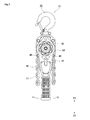
- FIG. 1 It is a front view which shows an example of the structure of the lever hoist to which the power transmission device for a lever hoist of this invention is attached. It is sectional drawing which shows the structure of the lever hoist shown in FIG. Of the lever hoists shown in FIG. 1, it is a partial cross-sectional view showing the vicinity of the brake device in an enlarged manner. It is a top view which shows the claw wheel and the claw member among the lever hoists shown in FIG. 1, and is the figure which shows the state in which the ratchet teeth are provided twice the odd number.
- FIG. 6 is an enlarged view showing the vicinity of the ratchet teeth of the claw wheel shown in FIG. It is a top view which shows the claw wheel and the claw member among the lever hoists shown in FIG. 1, and is the figure which shows the state which the ratchet teeth are provided twice the even number.
- the X direction is the axial direction of the drive shaft 25 arranged between the gear box (reference numeral omitted) on which the reduction gear 30 is arranged and the fast-rotating nigiri 60 (hereinafter referred to as “idle nigiri”).
- the X1 side is the side to which the idle nigiri 60 is attached, and the X2 side is the opposite gearbox side.
- the Z direction is the vertical direction (suspension direction; hoisting / lowering direction) of the lever hoist 10 in the suspended state, the Z1 side is the upper side in the suspended state, and the Z2 side is the lower side in the suspended state.
- FIG. 1 is a front view showing an example of the configuration of the lever hoist 10.
- FIG. 2 is a cross-sectional view showing the configuration of the lever hoist 10 shown in FIG.
- the lever hoist 10 includes a pair of frames 11 and 12, and an upper hook 22 is supported on the upper side (Z1 side) of the pair of frames 11 and 12. Further, a load sheave 20 around which the chain C1 is hung is supported between the pair of frames 11 and 12 in a rotatable state.
- the load sheave 20 is formed with an insertion hole 20a penetrating in the axial direction (X direction), and the drive shaft 25 is inserted through the insertion hole 20a.
- a male screw portion 26 that meshes with the female screw member 35 described later is provided on the outer peripheral side of the drive shaft 25 in the middle, and the other end side (X2 side) of the drive shaft 25 meshes with the large diameter gear portion 31 of the reduction gear 30.
- a pinion gear 27 is provided.
- the reduction gear 30 is integrally provided with a small-diameter gear portion 32 that meshes with the road gear 21 described above.
- a casing 13 is attached to the frame 11 to protect drive parts such as the reduction gear 30 and the load gear 21 described above.
- the male screw portion 26 described above meshes with the female screw portion 36 of the female screw member 35.
- the female screw member 35 is also provided with a switching gear 37 that can mesh with the switching claw 40 at a lower position (Z2 side) on the peripheral portion thereof.
- the switching claw 40 is, for example, a ratchet claw provided on one side and one on the other side of the operation lever 50 described later, and the operation lever 50 described later is rotated while the switching claw 40 is engaged with the switching gear 37. By moving it, the driving force is transmitted to the female screw member 35.
- the switching knob 45 is attached in a state of being coaxial with the switching claw 40, and the transmission of the driving force to the female screw member 35 is set to the winding direction or the winding direction by the switching operation of the switching knob 45. Can be switched.
- the winding switching claw 40 meshes with the switching gear 37.
- the switching gear 37 rotates in the winding direction but does not rotate in the winding direction. This corresponds to the hoisting state of the chain C1.
- a pair of engaging protrusions 46 are provided on the upper side (Z1 side) of the switching knob 45.
- one of the engaging protrusions 46 engages with the flange portion 65 of the idler nigiri 60, so that the idler nigiri 60 is on one side (X1) in the axial direction (X direction). It will not be pulled out to the side). Therefore, it is possible to maintain a state in which the urging spring (not shown) presses the brake mechanism.
- the winding switching claw 40 meshes with the switching gear 37.
- the switching gear 37 rotates in the winding direction but does not rotate in the winding direction. This corresponds to the unwound state of the chain C1.
- the other engaging protrusion 46 engages with the flange portion 65 of the idler nigiri 60, so that the idler nigiri 60 is not pulled out to one side (X1 side) in the axial direction (X direction). Therefore, it is possible to maintain a state in which the urging spring (not shown) presses the brake mechanism.
- the switching knob 45 when the lower side (Z2 side) of the switching knob 45 is positioned at the neutral position, which is a position between the winding direction and the winding direction (in this case, the switching knob 45 is oriented along the longitudinal direction of the operating lever 50). , Neither the hoisting switching claw 40 nor the hoisting switching claw 40 meshes with the switching gear 37. As a result, even if the operation lever 50 is rotated, neither the winding operation nor the winding down operation of the chain C1 is executed, and the chain C1 is in a free (idle) state. At this time, none of the pair of engaging protrusions 46 engages with the flange portion 65 of the idle nigiri 60. Therefore, the idle nigiri 60 can be pulled out to one side (X1 side) in the axial direction (X direction), and the state in which the urging spring (not shown) presses the brake mechanism can be relaxed.
- a cam member 55 is attached to the drive shaft 25 in a state in which it cannot rotate with respect to the drive shaft 25, and further idles on one end side (X1 side) in the axial direction (X direction) with respect to the cam member 55.
- a member called 60 is also attached to the drive shaft 25 in a non-rotatable state.
- the idle nigiri 60 is a substantially circular handle-shaped part that can rotate together with the drive shaft.
- a flange portion 65 is provided on the other side (X2 side) of the idle nigiri 60 in the axial direction (X direction).
- the idle nigiri 60 cannot be pulled out to one side (X1 side) in the axial direction (X direction). .. Therefore, it is possible to maintain a state in which the urging spring (not shown) presses the brake mechanism.
- the idle nigiri 60 is pushed toward the other side (X2 side) in the axial direction (X direction) at the time of hoisting and unwinding.
- the switching knob 45 when the switching knob 45 is in the neutral position (neutral state), the idler nigiri 60 can be pulled out to one side (X1 side) in the axial direction (X direction).
- the idle nigiri 60 is pulled out to one side (X1 side) in the axial direction (X direction)
- the pressing force of the urging spring urging the brake mechanism weakens, so that the brake is released and the brake is released by hand or the like. While gripping the chain C1, it can be freely pulled out in either the winding side or the winding side.
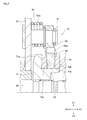
- FIG. 3 is a partial cross-sectional view of the lever hoist shown in FIG. 1 in which the vicinity of the brake device 70 is enlarged.
- a brake device 70 is arranged between the operating lever 50 and the drive shaft 25.
- the brake device 70 has a brake receiver 71, brake plates 72a and 72b, a claw wheel 80, a claw member 90, a claw shaft 91, a bush 92 and the like as main components.
- the brake receiver 71 has a flange portion 71a and a hollow boss portion 71b (corresponding to the boss portion).
- the flange portion 71a is a portion provided with a diameter larger than that of the hollow boss portion 71b, and is capable of receiving the brake plate 72a.
- the hollow boss portion 71b is located on the female screw member 35 side (X1 side) of the flange portion 71a, and pivotally supports the claw wheel 80 via the bush 92.
- the inner peripheral side of the hollow boss portion 71b meshes with the drive shaft 25 by key coupling, spline coupling, or the like, so that the drive shaft 25 and the brake receiver 71 rotate integrally.
- brake plates 72a and 72b are pivotally supported by the hollow boss portion 71b between the flange portion 71a and the claw wheel 80 and between the female screw member 35 and the claw wheel 80, respectively.
- the brake plates 72a and 72b are friction materials formed by, for example, sintering a predetermined material.
- the female screw member 35 presses the brake plates 72a and 72b by the screw tightening action of the female screw member 35 and the brake receiver 71 (flange portion 71a).
- the brake plates 72a and 72b are strongly pressed, and the claw wheel 80 is strongly pressed by the brake plates 72a and 72b.
- the strong pressing described above causes the drive shaft 25 to move in the winding direction. Rotation is dampened.
- the claw wheel 80 can rotate in the winding direction, so that the rotation in the winding direction is not blocked by the claw wheel 80. Therefore, by operating the operating lever 50, the female screw member 35, the brake plates 72a and 72b, the claw wheel 80, and the brake receiver 71 integrally rotate the drive shaft 25, and the driving force thereof is transmitted via the reduction gear 30.
- the chain C1 is wound up by being transmitted to the load sheave 20.
- ratchet teeth 83 (described later) provided on the claw wheel 80 mesh with the tip portion 90a of the claw member 90.
- a ratchet mechanism that prevents rotation of the claw wheel 80 in the winding direction and allows rotation in the winding direction is configured except when the switching knob 45 is switched in the winding direction to operate the operation lever 50 by the engagement. Will be done.
- a bush 92 is provided on the outer peripheral side of the hollow boss portion 71b of the brake receiver 71, and a claw wheel 80 is provided on the outer peripheral side of the bush 92.
- a claw shaft 91 is attached to the frame 12, and a claw member 90 is rotatably supported on the claw shaft 91. Further, a coil portion 93a of the torsion spring 93 is attached to the claw shaft 91, and the torsion spring 93 gives an urging force in a direction in which the claw member 90 is pressed against the ratchet teeth 83 (described later) of the claw wheel 80. ..
- a pair of claw members 90 are provided, and are arranged point-symmetrically with respect to the central axis of the drive shaft 25 in the circumferential direction of the claw wheel 80.
- FIG. 4 is a plan view showing the claw wheel 80 and the claw member 90, showing an example of a configuration in which the number of ratchet teeth 83 is twice an odd number, and is a plan view showing the arrangement of the claw members 90.
- the claw wheel 80 is provided with a ring-shaped ring-shaped portion 81, and the front surface and the back surface of the ring-shaped portion 81 are portions on which the above-mentioned brake plates 72a and 72b are pressed. ..
- the bush 92 described above in the center hole 82 located at the center of the ring-shaped portion 81 the claw wheel 80 is rotatably supported.
- the ratchet tooth 83 protrudes from the ring-shaped portion 81 toward the outer periphery.
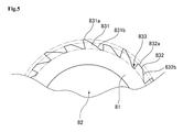
- FIG. 5 is an enlarged view showing the vicinity of the ratchet teeth 83 of the claw wheel 80.
- the ratchet tooth 83 has a high tooth 831 and a low tooth 832. Of these, the tip of the high tooth 831 (high tooth tip 831a) protrudes toward the outer diameter side of the tip of the low tooth 832 (low tooth tip 832a).
- the tip 90a of the claw member 90 is located on the radial center side of the position where the tip 90a contacts the low tooth tip 832a due to the urging force of the torsion spring 93, rather than the position where the tip 90a contacts the high tooth tip 831a. (Inner diameter side).
- the high teeth 831 and the low teeth 832 are formed alternately adjacent to each other, and their lengths (pitch) in the circumferential direction are provided to be equal. Further, assuming that the valley portion 833 is between the high tooth 831 and the low tooth 832, the inclination angle of the tapered portion 831b from the valley portion 833 toward the high tooth tip portion 831a on the tip side of the high tooth 831 is from the valley portion 833 to the low tooth. It is provided so as to be equal to the inclination angle of the tapered portion 832b toward the low tooth tip portion 832a on the distal end side of the 832.
- the low tooth 832 is provided in a form in which the tip end side of the high tooth 831 is cut.
- the low tooth tip portion 832a of the low tooth 832 may be a part of an arc concentric with the claw wheel 80.
- the low tooth tip portion 832a may have a shape other than a part of the arc (for example, a straight line), or may be a part of an arc that is not concentric with the claw wheel 80.
- the total number of ratchet teeth 83 which is the sum of the high teeth 831 and the low teeth 832, is an even number.
- the number of ratchet teeth 83 is double the odd number
- the tip 90a of one claw member 90 is pressed against the high tooth 831
- the other The claw member 90 will be pressed against the low teeth 832. Since either one of the claw members 90 or the other claw member 90 is always pressed against the low tooth 832, at least the tip 90a of the claw member 90 pressed against the low tooth 832 when the reversal occurs is adjacent. It will always collide with the high teeth 831 (back). Therefore, the reversal of the claw wheel 80 can be reliably prevented.
- there are a total of 22 ratchet teeth 83 there are a total of 22 ratchet teeth 83, but the number of ratchet teeth 83 may be any number as long as the odd number is doubled.
- the number of teeth of the ratchet tooth 83 which is the sum of the high teeth 831 and the low teeth 832, is double the even number (the number of multiples of 4), as shown in FIG. 6, one of the claw members 90 When the tip 90a of the head is pressed against the high tooth 831, the other claw member 90 is also pressed against the high tooth 831. Further, when the tip 90a of one claw member 90 is pressed against the low tooth 832, the other claw member 90 is also pressed against the low tooth 832.
- the tip 90a of the claw member 90 that was pressed against the low tooth 832 when the reversal occurred always collided with (the back) of the adjacent high tooth 831, or the claw that was pressed against the high tooth 831.
- the tip 90a of the member 90 can sufficiently prevent the claw wheel 80 from reversing because the distance between the adjacent high teeth 831 is wider than the distance between the ratchet teeth having the same height provided by the current claw wheel.
- the total number of ratchet teeth 83 is 20, but the number of ratchet teeth 83 may be any number as long as the number of teeth is double an even number.
- the brake receiver 71 is non-rotatably supported by the drive shaft 25 and has a flange portion 71a and a hollow boss portion 71b (boss portion), and the drive shaft.
- a female screw member 35 rotatably supported by 25 and screwed into a male screw portion 26 provided on the outer periphery of the drive shaft 25, sandwiched between a flange portion 71a and a female screw member 35 facing each other, and on the outer peripheral side.
- a claw wheel 80 provided with a ratchet tooth 83 for regulating the rotation direction in one direction, at least one of a flange portion 71a and a female screw member 35, brake plates 72a and 72b arranged between the claw wheels 80, and a ratchet tooth.
- the claw wheel 80 is provided with at least one claw member 90, which meshes with the 83 and engages the tip portion 90a (tip side) with the valley portion 833 located between the adjacent ratchet teeth 83, and the claw wheel 80 has high teeth.
- the 831 and the low tooth 832 having a lower protrusion height from the rotation center of the ratchet 80 than the high tooth 831 are provided.
- the switching knob 45 is erroneously switched in the winding direction while the tip 90a of the claw member 90 is in contact with the high tooth tip 831a on the tip side of the high tooth 831. ..
- the claw wheel 80 tries to rotate (reverse) vigorously due to the action of the load of the load.
- the claw wheel 80 has high teeth 831 and low teeth 832. Therefore, the tip 90a of the claw member 90 after passing through the low tooth tip 832a of the low tooth 832 collides with the back of the adjacent high tooth 831. Therefore, it is possible to prevent the claw wheel 80 from reversing.
- the claw wheel 80 is provided with high teeth 831 and low teeth 832 alternately.
- the tip 90a of at least one claw member 90 when the tip 90a of at least one claw member 90 is in contact with the low tooth tip 832a of the low tooth 832, when the claw wheel 80 starts to rotate (reverse), It immediately collides with the back of the next tooth, the high tooth 831.
- the tip 90a of at least one claw member 90 when the tip 90a of at least one claw member 90 is in contact with the high tooth tip 831a of the high tooth 831, the claw wheel 80 starts to rotate (reverse) and temporarily overcomes the low tooth tip 832a. Also immediately collides with the back of the high tooth 831. Therefore, the reversal of the claw wheel 80 can be prevented at an early stage.
- the present embodiment it is preferable to provide twice as many ratchet teeth 83 as an odd number.
- the tip 90a of one claw member 90 is pressed against the high teeth 831, the other claw member 90 is pressed against the low teeth 832.
- the tip 90a of the claw member 90 can be pressed against the low tooth tip 832a on the inner diameter side of the high tooth tip 831a of the claw wheel 80, the reversal of the claw wheel 80 can be reliably prevented.
- the low tooth tip portion 832a on the tip side of the low tooth 832 can be formed so as to form a part of an arc.
- the circumferential length of the low tooth tip 832a is longer than the circumferential length of the high tooth tip 831a. Therefore, the time for the tip 90a of the claw member 90 to contact the low tooth tip 832a can be lengthened as compared with the high tooth tip 831a, so that the reversal of the claw wheel 80 can be prevented more reliably. Can be done. Further, since the low tooth tip portion 832a can be easily processed by using, for example, a machine tool, productivity can be improved.
- the idler device for switching between idler and non-idle by operating the idler nigiri 60 is described, but other types of idler devices such as an automatic idler method are provided. It may be a lever hoist.
- the brake device 70 is applied to the lever hoist 10 is described.
- the above-mentioned brake device may be applied to a hoist other than the lever hoist, such as a chain block or the like.
- a case where a pair of claw members 90 are provided is described. However, only one claw member 90 may be provided, or three or more claw members 90 may be provided. When three or more claw members 90 are provided, the claw members 90 are evenly arranged on the outer peripheral side of the claw wheel 80, and one claw member 90 is located between the ratchet teeth adjacent to the high teeth. It is preferred that at least one other claw member engages the valley located between the ratchet teeth adjacent to the low tooth when partially engaged.
- the plurality of claw members 90 are not evenly arranged on the outer peripheral side of the claw wheel 80. In that case, it is preferable to arrange the claw members 90 so that the radial forces acting on the claw shafts 21 are equal.
- two of the four claw members 90 may be arranged line-symmetrically with respect to a line orthogonal to the drive shaft 25.
- a pair of claw members 90 are provided, and it is most preferable that the pair of claw members 90, 90 have the same shape and are arranged at point-symmetrical positions about the drive shaft 25, but they are engaged with each other.
- the claw member 90 may have a different shape as long as the shape and arrangement are such that the tip 90a of each claw member 90 is simultaneously engaged with the valley portion 833.
- the engaging position of the tip portion 90a is a point-symmetrical position, and the positions may be offset by an even number of teeth from each other. It is not preferable to shift the engagement position more than necessary because it increases.
- the brake plate 72 is arranged separately on the claw wheel 80, but friction members may be formed by baking on both sides of the claw wheel 80.
- the male screw portion 26 of the drive shaft 25 and the female screw portion 36 of the female screw member 35 are screwed together. It has a structure.
- the female screw member 35 may be provided separately from the drive shaft 25 (for example, a male screw provided on the outer peripheral portion of the hollow shaft extending the hollow boss portion 71b of the brake receiver 71), and further, a load using a cam is used. It may be a mechanism that converts torque into thrust force.
- the brake device 70 of the lever hoist 10 has been described as an example, but if the invention is broadly grasped, it can be said that the present invention relates to the ratchet mechanism. That is, the present invention is a ratchet mechanism that allows rotation of the ratchet wheel in only one direction by providing a claw wheel having a large number of ratchet teeth formed on the outer periphery and at least one claw member that meshes with the ratchet teeth.
- the ratchet teeth are a ratchet mechanism in which high teeth having a high protrusion height from the center of the claw wheel and low teeth having a low protrusion height from the center of the claw wheel exist.
- the ratchet mechanism By configuring the ratchet mechanism in this way, even when reversal occurs when the tip of the claw member is located at the tip of the high tooth or low tooth, at least the back of the next high tooth (high tooth is formed).
- the tip of the claw member collides with the (inclination) and enters the valley between the ratchet teeth. Therefore, it is possible to immediately and surely prevent the reversal of the claw wheel.
- two claw members are provided at symmetrical positions. Further, it is preferable that the high teeth and the low teeth are provided alternately. Further, it is preferable that the number of ratchet teeth is twice an odd number.
- the two claw members at symmetrical positions, it is possible to eliminate the bias of the stress applied to the claw wheel. Further, by alternately providing the high teeth and the low teeth, when a reversal occurs, the tip of the claw member can collide with the back of the nearest high tooth. In addition, by making the number of ratchet teeth twice an odd number, when the tip of one claw member in a symmetrical position is at the tip of a high tooth, the tip of the other claw member is located at the tip of a low tooth. Therefore, when the reversal occurs, at least the tip of the claw member located at the tip of the low tooth always collides with the back of the adjacent high tooth, so that the reversal of the claw wheel can be prevented immediately and surely. ..
- Such a ratchet mechanism is applied to a lever hoist braking device that resists a unidirectional input torque, for example, as described in the above embodiment, in order to prevent the claw wheel that constitutes the braking device from reversing. Especially effective.
Landscapes
- Engineering & Computer Science (AREA)
- Mechanical Engineering (AREA)
- Transmission Devices (AREA)
- Braking Arrangements (AREA)
- Braking Elements And Transmission Devices (AREA)
Priority Applications (11)
| Application Number | Priority Date | Filing Date | Title |
|---|---|---|---|
| KR1020227038945A KR20230002588A (ko) | 2020-04-14 | 2021-01-28 | 브레이크 장치, 레버 호이스트 및 래칫기구 |
| CN202180028007.2A CN115397763B (zh) | 2020-04-14 | 2021-01-28 | 制动装置、手扳葫芦以及棘轮机构 |
| US17/918,334 US12479703B2 (en) | 2020-04-14 | 2021-01-28 | Brake device, lever hoist, and ratchet mechanism |
| CA3175208A CA3175208A1 (en) | 2020-04-14 | 2021-01-28 | Brake device, lever hoist, and ratchet mechanism |
| JP2022515209A JP7460265B2 (ja) | 2020-04-14 | 2021-01-28 | ブレーキ装置、レバーホイストおよびラチェット機構 |
| DE112021002284.9T DE112021002284T5 (de) | 2020-04-14 | 2021-01-28 | Bremsvorrichtung, hebelzug und sperrklinkenmechanismus |
| AU2021257687A AU2021257687A1 (en) | 2020-04-14 | 2021-01-28 | Brake device, lever hoist, and ratchet mechanism |
| BR112022020696A BR112022020696A2 (pt) | 2020-04-14 | 2021-01-28 | Dispositivo de freio, guincho de alavanca, e mecanismo de catraca |
| ZA2022/11129A ZA202211129B (en) | 2020-04-14 | 2022-10-11 | Brake device, lever hoist, and ratchet mechanism |
| JP2024039921A JP7762247B2 (ja) | 2020-04-14 | 2024-03-14 | ラチェット機構 |
| US19/381,007 US20260062263A1 (en) | 2020-04-14 | 2025-11-06 | Brake device, lever hoist, and ratchet mechanism |
Applications Claiming Priority (2)
| Application Number | Priority Date | Filing Date | Title |
|---|---|---|---|
| JP2020072176 | 2020-04-14 | ||
| JP2020-072176 | 2020-04-14 |
Related Child Applications (2)
| Application Number | Title | Priority Date | Filing Date |
|---|---|---|---|
| US17/918,334 A-371-Of-International US12479703B2 (en) | 2020-04-14 | 2021-01-28 | Brake device, lever hoist, and ratchet mechanism |
| US19/381,007 Continuation US20260062263A1 (en) | 2020-04-14 | 2025-11-06 | Brake device, lever hoist, and ratchet mechanism |
Publications (1)
| Publication Number | Publication Date |
|---|---|
| WO2021210236A1 true WO2021210236A1 (ja) | 2021-10-21 |
Family
ID=78084204
Family Applications (1)
| Application Number | Title | Priority Date | Filing Date |
|---|---|---|---|
| PCT/JP2021/002971 Ceased WO2021210236A1 (ja) | 2020-04-14 | 2021-01-28 | ブレーキ装置、レバーホイストおよびラチェット機構 |
Country Status (11)
| Country | Link |
|---|---|
| US (2) | US12479703B2 (https=) |
| JP (2) | JP7460265B2 (https=) |
| KR (1) | KR20230002588A (https=) |
| CN (1) | CN115397763B (https=) |
| AU (1) | AU2021257687A1 (https=) |
| BR (1) | BR112022020696A2 (https=) |
| CA (1) | CA3175208A1 (https=) |
| DE (1) | DE112021002284T5 (https=) |
| TW (1) | TWI895366B (https=) |
| WO (1) | WO2021210236A1 (https=) |
| ZA (1) | ZA202211129B (https=) |
Families Citing this family (3)
| Publication number | Priority date | Publication date | Assignee | Title |
|---|---|---|---|---|
| CA3175208A1 (en) * | 2020-04-14 | 2021-10-21 | Kito Corporation | Brake device, lever hoist, and ratchet mechanism |
| CN116817848B (zh) * | 2023-03-07 | 2026-02-06 | 安徽农业大学 | 一种垂直高度量测仪及测量方法 |
| CN118359102B (zh) * | 2024-05-21 | 2024-10-15 | 广东路通达建设工程有限公司 | 一种市政道路管道铺设结构 |
Citations (4)
| Publication number | Priority date | Publication date | Assignee | Title |
|---|---|---|---|---|
| JPS4821857Y1 (https=) * | 1970-06-20 | 1973-06-26 | ||
| JPH0653392U (ja) * | 1992-12-28 | 1994-07-19 | 株式会社シマノ | 自転車用の変速操作装置 |
| JPH079896Y2 (ja) * | 1989-01-23 | 1995-03-08 | 株式会社ニッチ | 牽引巻上機 |
| JP2008222393A (ja) * | 2007-03-14 | 2008-09-25 | Kito Corp | 巻上牽引機におけるブレーキ装置 |
Family Cites Families (15)
| Publication number | Priority date | Publication date | Assignee | Title |
|---|---|---|---|---|
| US2803489A (en) * | 1955-12-21 | 1957-08-20 | Albino S Zito | Load-lifting device of the self-gripping type |
| US3138030A (en) * | 1961-02-14 | 1964-06-23 | American Mach & Foundry | Pawl and ratchet mechanisms |
| JPS52127357A (en) * | 1976-04-19 | 1977-10-25 | Seikosha Kk | 22stage position retaining device |
| US4287396A (en) * | 1980-01-16 | 1981-09-01 | Greenwald Electro-Mechanical Consultants, Inc. | Control device for a coin operated mechanism |
| FR2642786B1 (fr) * | 1989-02-07 | 1991-05-10 | Europ Agence Spatiale | Dispositif de verrouillage lineaire ou circulaire, du type dit a cliquet, autobloquant et a deblocage automatique |
| CN2083332U (zh) | 1990-04-21 | 1991-08-21 | 刘克坚 | 节能拉线开关 |
| CN2075817U (zh) * | 1990-08-03 | 1991-04-24 | 黎文良 | 拉线开关 |
| JPH06263396A (ja) | 1993-03-11 | 1994-09-20 | Ookubo Haguruma Kogyo Kk | 減速機 |
| JP3086874B2 (ja) * | 1998-12-02 | 2000-09-11 | 象印チエンブロック株式会社 | チェーンレバーホイスト |
| US6517054B2 (en) * | 2001-04-23 | 2003-02-11 | Vital Kogyo Kabushiki Kaisha | Lever hoist with overload preventing device |
| JP2011102182A (ja) | 2009-11-12 | 2011-05-26 | Kito Corp | 巻上機におけるメカニカルブレーキ装置 |
| CN202625719U (zh) | 2012-04-24 | 2012-12-26 | 吾信工业股份有限公司 | 棘轮刹车结构 |
| JP2014108839A (ja) | 2012-11-30 | 2014-06-12 | Kito Corp | チェーンブロックおよびロードチェーン |
| CA2948450C (en) | 2014-05-16 | 2018-03-13 | Kito Corporation | Chain block |
| CA3175208A1 (en) * | 2020-04-14 | 2021-10-21 | Kito Corporation | Brake device, lever hoist, and ratchet mechanism |
-
2021
- 2021-01-28 CA CA3175208A patent/CA3175208A1/en active Pending
- 2021-01-28 AU AU2021257687A patent/AU2021257687A1/en active Pending
- 2021-01-28 DE DE112021002284.9T patent/DE112021002284T5/de active Pending
- 2021-01-28 KR KR1020227038945A patent/KR20230002588A/ko active Pending
- 2021-01-28 BR BR112022020696A patent/BR112022020696A2/pt unknown
- 2021-01-28 WO PCT/JP2021/002971 patent/WO2021210236A1/ja not_active Ceased
- 2021-01-28 JP JP2022515209A patent/JP7460265B2/ja active Active
- 2021-01-28 US US17/918,334 patent/US12479703B2/en active Active
- 2021-01-28 CN CN202180028007.2A patent/CN115397763B/zh active Active
- 2021-02-25 TW TW110106651A patent/TWI895366B/zh active
-
2022
- 2022-10-11 ZA ZA2022/11129A patent/ZA202211129B/en unknown
-
2024
- 2024-03-14 JP JP2024039921A patent/JP7762247B2/ja active Active
-
2025
- 2025-11-06 US US19/381,007 patent/US20260062263A1/en active Pending
Patent Citations (4)
| Publication number | Priority date | Publication date | Assignee | Title |
|---|---|---|---|---|
| JPS4821857Y1 (https=) * | 1970-06-20 | 1973-06-26 | ||
| JPH079896Y2 (ja) * | 1989-01-23 | 1995-03-08 | 株式会社ニッチ | 牽引巻上機 |
| JPH0653392U (ja) * | 1992-12-28 | 1994-07-19 | 株式会社シマノ | 自転車用の変速操作装置 |
| JP2008222393A (ja) * | 2007-03-14 | 2008-09-25 | Kito Corp | 巻上牽引機におけるブレーキ装置 |
Also Published As
| Publication number | Publication date |
|---|---|
| ZA202211129B (en) | 2023-06-28 |
| US12479703B2 (en) | 2025-11-25 |
| CN115397763A (zh) | 2022-11-25 |
| US20230143207A1 (en) | 2023-05-11 |
| JPWO2021210236A1 (https=) | 2021-10-21 |
| KR20230002588A (ko) | 2023-01-05 |
| CN115397763B (zh) | 2026-02-27 |
| TWI895366B (zh) | 2025-09-01 |
| JP2024072859A (ja) | 2024-05-28 |
| TW202138279A (zh) | 2021-10-16 |
| BR112022020696A2 (pt) | 2022-11-29 |
| CA3175208A1 (en) | 2021-10-21 |
| US20260062263A1 (en) | 2026-03-05 |
| JP7762247B2 (ja) | 2025-10-29 |
| AU2021257687A1 (en) | 2022-11-03 |
| JP7460265B2 (ja) | 2024-04-02 |
| DE112021002284T5 (de) | 2023-02-09 |
Similar Documents
| Publication | Publication Date | Title |
|---|---|---|
| WO2021210236A1 (ja) | ブレーキ装置、レバーホイストおよびラチェット機構 | |
| WO2009152666A1 (zh) | 动力绞车变速控制装置 | |
| KR900006651B1 (ko) | 수동식 권상기 | |
| JP3280315B2 (ja) | レバー式捲上機 | |
| JP2000169091A (ja) | チェーンレバーホイスト | |
| JPH10220491A (ja) | 荷役機械の過負荷制御機構 | |
| JP2782061B2 (ja) | レバー式捲上機 | |
| JP7705224B2 (ja) | レバーホイスト | |
| CN115702114B (zh) | 旋转锁定装置、手扳葫芦以及卷扬机 | |
| EP0131380B1 (en) | Hoist | |
| JP6947716B2 (ja) | レバーホイスト用動力伝達装置 | |
| CN115515890A (zh) | 货物掉落防止装置以及葫芦 | |
| KR100686582B1 (ko) | 정, 역회전이 자유로운 윈치장치 | |
| JP5890216B2 (ja) | 負荷感応自動変速装置を内蔵した巻上機 | |
| JP4573600B2 (ja) | 巻上機における過負荷防止装置 | |
| KR20030085922A (ko) | 낚시용 릴 | |
| BR122026001244A2 (pt) | Dispositivo de freio, guincho de alavanca, e mecanismo de catraca | |
| JP2000086168A (ja) | 手動式チェーンブロック | |
| JPS6338231Y2 (https=) | ||
| JP2536706Y2 (ja) | レバー式捲上牽引装置 | |
| JP2504520Y2 (ja) | レバ―式捲上牽引装置 | |
| JP2000128488A (ja) | チェーンブロック | |
| JPH11201239A (ja) | 手動操作軸付き減速機 | |
| JP2006089255A (ja) | チェーンブロック | |
| JPS61243798A (ja) | レバ−式捲上牽引装置 |
Legal Events
| Date | Code | Title | Description |
|---|---|---|---|
| 121 | Ep: the epo has been informed by wipo that ep was designated in this application |
Ref document number: 21788729 Country of ref document: EP Kind code of ref document: A1 |
|
| ENP | Entry into the national phase |
Ref document number: 3175208 Country of ref document: CA |
|
| REG | Reference to national code |
Ref country code: BR Ref legal event code: B01A Ref document number: 112022020696 Country of ref document: BR |
|
| ENP | Entry into the national phase |
Ref document number: 2022515209 Country of ref document: JP Kind code of ref document: A |
|
| ENP | Entry into the national phase |
Ref document number: 2021257687 Country of ref document: AU Date of ref document: 20210128 Kind code of ref document: A |
|
| ENP | Entry into the national phase |
Ref document number: 20227038945 Country of ref document: KR Kind code of ref document: A |
|
| ENP | Entry into the national phase |
Ref document number: 112022020696 Country of ref document: BR Kind code of ref document: A2 Effective date: 20221011 |
|
| 122 | Ep: pct application non-entry in european phase |
Ref document number: 21788729 Country of ref document: EP Kind code of ref document: A1 |
|
| WWG | Wipo information: grant in national office |
Ref document number: 17918334 Country of ref document: US |