WO2021205913A1 - 加湿器 - Google Patents
加湿器 Download PDFInfo
- Publication number
- WO2021205913A1 WO2021205913A1 PCT/JP2021/013010 JP2021013010W WO2021205913A1 WO 2021205913 A1 WO2021205913 A1 WO 2021205913A1 JP 2021013010 W JP2021013010 W JP 2021013010W WO 2021205913 A1 WO2021205913 A1 WO 2021205913A1
- Authority
- WO
- WIPO (PCT)
- Prior art keywords
- distribution port
- upper lid
- baffle
- water chamber
- port
- Prior art date
- Legal status (The legal status is an assumption and is not a legal conclusion. Google has not performed a legal analysis and makes no representation as to the accuracy of the status listed.)
- Ceased
Links
Images





Classifications
-
- A—HUMAN NECESSITIES
- A61—MEDICAL OR VETERINARY SCIENCE; HYGIENE
- A61M—DEVICES FOR INTRODUCING MEDIA INTO, OR ONTO, THE BODY; DEVICES FOR TRANSDUCING BODY MEDIA OR FOR TAKING MEDIA FROM THE BODY; DEVICES FOR PRODUCING OR ENDING SLEEP OR STUPOR
- A61M16/00—Devices for influencing the respiratory system of patients by gas treatment, e.g. ventilators; Tracheal tubes
- A61M16/10—Preparation of respiratory gases or vapours
- A61M16/14—Preparation of respiratory gases or vapours by mixing different fluids, one of them being in a liquid phase
- A61M16/16—Devices to humidify the respiration air
-
- A—HUMAN NECESSITIES
- A61—MEDICAL OR VETERINARY SCIENCE; HYGIENE
- A61M—DEVICES FOR INTRODUCING MEDIA INTO, OR ONTO, THE BODY; DEVICES FOR TRANSDUCING BODY MEDIA OR FOR TAKING MEDIA FROM THE BODY; DEVICES FOR PRODUCING OR ENDING SLEEP OR STUPOR
- A61M16/00—Devices for influencing the respiratory system of patients by gas treatment, e.g. ventilators; Tracheal tubes
- A61M16/0057—Pumps therefor
- A61M16/0066—Blowers or centrifugal pumps
-
- A—HUMAN NECESSITIES
- A61—MEDICAL OR VETERINARY SCIENCE; HYGIENE
- A61M—DEVICES FOR INTRODUCING MEDIA INTO, OR ONTO, THE BODY; DEVICES FOR TRANSDUCING BODY MEDIA OR FOR TAKING MEDIA FROM THE BODY; DEVICES FOR PRODUCING OR ENDING SLEEP OR STUPOR
- A61M16/00—Devices for influencing the respiratory system of patients by gas treatment, e.g. ventilators; Tracheal tubes
- A61M16/06—Respiratory or anaesthetic masks
-
- A—HUMAN NECESSITIES
- A61—MEDICAL OR VETERINARY SCIENCE; HYGIENE
- A61M—DEVICES FOR INTRODUCING MEDIA INTO, OR ONTO, THE BODY; DEVICES FOR TRANSDUCING BODY MEDIA OR FOR TAKING MEDIA FROM THE BODY; DEVICES FOR PRODUCING OR ENDING SLEEP OR STUPOR
- A61M16/00—Devices for influencing the respiratory system of patients by gas treatment, e.g. ventilators; Tracheal tubes
- A61M16/08—Bellows; Connecting tubes ; Water traps; Patient circuits
- A61M16/0875—Connecting tubes
-
- A—HUMAN NECESSITIES
- A61—MEDICAL OR VETERINARY SCIENCE; HYGIENE
- A61M—DEVICES FOR INTRODUCING MEDIA INTO, OR ONTO, THE BODY; DEVICES FOR TRANSDUCING BODY MEDIA OR FOR TAKING MEDIA FROM THE BODY; DEVICES FOR PRODUCING OR ENDING SLEEP OR STUPOR
- A61M2206/00—Characteristics of a physical parameter; associated device therefor
- A61M2206/10—Flow characteristics
- A61M2206/20—Flow characteristics having means for promoting or enhancing the flow, actively or passively
-
- F—MECHANICAL ENGINEERING; LIGHTING; HEATING; WEAPONS; BLASTING
- F24—HEATING; RANGES; VENTILATING
- F24F—AIR-CONDITIONING; AIR-HUMIDIFICATION; VENTILATION; USE OF AIR CURRENTS FOR SCREENING
- F24F6/00—Air-humidification, e.g. cooling by humidification
- F24F6/02—Air-humidification, e.g. cooling by humidification by evaporation of water in the air
- F24F6/04—Air-humidification, e.g. cooling by humidification by evaporation of water in the air using stationary unheated wet elements
Definitions
- This disclosure relates to a humidifier.
- the humidifier described in Patent Document 1 includes a water chamber in which water is stored.
- the outer wall of the water chamber is opened with an inflow port for introducing air from the outside.
- an outflow port for discharging air in the water chamber is opened in the outer wall facing the outer wall provided with the inflow port.
- the outlet and the inlet are arranged at substantially the same height.
- a dividing member that divides the inflow port side and the outflow port side into different areas is arranged inside the water chamber.
- the water in the water chamber is stored in the area on the outlet side.
- the dividing member is provided with a through hole for air to flow from the area on the inflow port side to the area on the outflow port side.
- one aspect of the present disclosure includes a water chamber capable of storing water inside and having a first distribution port and a second distribution port for air to flow, and the water chamber is provided with a water chamber.
- a tank having an opening at the top and an upper lid that covers the opening apart from the bottom surface of the tank are provided, and at least the second distribution port of the first distribution port and the second distribution port is the tank. It penetrates one main surface of the upper lid facing the inside of the space and the other main surface located outside the space of the tank, and at least a part of the second distribution port is formed on one main surface of the upper lid.
- a first baffle to cover and a second baffle located between the first distribution port and the second distribution port in a plan view of one main surface of the upper lid are provided, and the first baffle and the upper lid are provided.
- the main surface forms a third distribution port, a flow path communicating the third distribution port and the second distribution port is formed, and the direction in which the third distribution port opens is the first.
- the direction in which the first distribution port opens is different, and the second baffle is located on a straight line connecting the third distribution port and the first distribution port with a plan view of one main surface of the upper lid. It is a humidifier that extends in a direction that intersects the straight path.
- the air that has flowed into the water chamber of the humidifier passes through the first flow port, the third flow port of the first baffle, and the second flow port, and is discharged to the outside of the water chamber.
- a second baffle is arranged on a straight line connecting the first distribution port and the third distribution port so as to block the straight line. Therefore, at least a part of the air that has passed through the first distribution port bypasses the second baffle and reaches the third distribution port. As a result, the air flow path between the first distribution port and the third distribution port becomes long, and the air is easily humidified.
- the air passing through the inside of the humidifier is easily humidified.
- CPAP device Continuus Positive Airway Pressure device
- the CPAP device 10 is composed of a blower unit 100 and a base unit 200.
- the blower unit 100 is attached to the base unit 200, the CPAP device 10 has a substantially rectangular parallelepiped shape as a whole.
- the direction in which the long side extends when the CPAP device 10 is viewed in a plan view is defined as the longitudinal direction
- the direction in which the short side extends is defined as the width direction.
- the blower unit 100 of the CPAP device 10 has a substantially rectangular parallelepiped shape. Although not shown, the inside of the blower unit 100 contains a passage through which air flows and a blower fan for pumping air in the passage.
- a switch 101 is installed on the upper surface of the blower unit 100. By operating this switch 101, on / off of the blower fan inside the blower unit 100 is controlled.
- the base unit 200 of the CPAP device 10 is L-shaped when viewed from the side in the width direction. Then, by attaching the blower unit 100 to the inside of the L-shape of the base unit 200, the CPAP device 10 has a substantially rectangular parallelepiped shape as described above.
- the upper outer cover portion 202 is removable with respect to the lower base portion 201. Further, inside the base unit 200, a passage for air supplied to the blower unit 100 and a silencer for muting the sound when air passes through the passage are provided. Further, inside the base unit 200, a humidifier 20 for humidifying the air supplied from the blower unit 100 is stored. The details of the humidifier 20 will be described later.
- the conduit 50 of the humidifier 20 projects from the outer cover portion 202 of the base unit 200.
- a mask 91 is attached to the conduit 50 via an air tube 90.
- the mask 91 is attached so as to cover the nose or mouth of the user 92.
- blower unit 100 When the blower unit 100 is attached to the base unit 200, air is supplied to the blower unit 100 through the passage in the base unit 200. Then, the air blown from the blower unit 100 is supplied to the humidifier 20 in the base unit 200 to be humidified. After that, humidified air is supplied to the mask 91 through the conduit 50 of the humidifier 20 and the air tube 90.
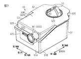
- the humidifier 20 includes a water chamber 30.
- the water chamber 30 is generally rectangular parallelepiped and has a hollow inside.
- the tank 31 of the water chamber 30 has a substantially square box shape as a whole. That is, the tank 31 has four side surface portions 31A and a bottom surface portion 31B connected to the lower ends of these side surface portions 31A. A space capable of storing water is formed by the four side surface portions 31A and the bottom surface portion 31B. Further, an opening of the tank 31 is formed by the upper edge of each side surface portion 31A of the tank 31.
- the water chamber 30 is provided with an upper lid 32 that covers the opening of the tank 31 apart from the bottom surface portion 31B of the tank 31.
- the upper lid 32 has a top plate 32A corresponding to the opening shape of the tank 31. From the edge of the top plate 32A from the first end side in the longitudinal direction, the side wall 32B rises toward the tank 31 side. The side wall 32B reaches a part of both edges of the top plate 32A in the width direction.
- a plate-shaped first locking portion 32C extends downward from the lower edge of the side wall 32B.
- the first locking portion 32C is arranged at the central portion in the width direction of the side wall 32B.
- the through hole 32D penetrates.
- a plate-shaped second locking portion 32E extends downward from the edge of the upper lid 32 on the second end side in the longitudinal direction.
- the second locking portion 32E is arranged at the center portion in the width direction at the edge on the second end side in the longitudinal direction of the upper lid 32.
- the through hole 32F penetrates.
- the through hole 32D of the first locking portion 32C and the through hole 32F of the second locking portion 32E of the upper lid 32 fit into a protrusion (not shown) of the tank 31.
- the upper lid 32 is attached to the tank 31.
- the flow pipe 300 as the second pipe penetrates.
- the flow pipe 300 communicates with the inside and outside of the water chamber 30 and is a pipe for supplying air into the water chamber 30.
- the flow pipe 300 can be roughly divided into an upstream portion 301 extending in a substantially longitudinal direction and a downstream portion 302 extending in a direction intersecting the extending direction of the upstream portion 301. That is, the flow pipe 300 is curved and extends as a whole.
- the upstream portion 301 has a substantially circular tubular shape.
- the upstream portion 301 penetrates the side wall 32B.
- the upstream portion 301 is arranged closer to the first end side than the center of the side wall 32B in the width direction.
- a downstream portion 302 is connected to the downstream end of the upstream portion 301.
- the downstream portion 302 has a semicircularly curved plate shape.
- the inner surface of the space of the tank 31 is the inner surface 33A and the outer surface of the space is the outer surface 33B when the upper lid 32 is attached to the tank 31.
- the air flow path is partitioned by the curved inner surface of the downstream portion 302 and the inner surface 33A of the top plate 32A.
- the downstream portion 302 extends obliquely from the downstream end of the upstream portion 301 toward the second end side in the width direction of the upper lid 32.
- the downstream portion 302 reaches the edge portion on the second end side in the width direction of the upper lid 32.
- an opening 311 as a fourth distribution port is opened at the downstream end of the downstream portion 302, that is, at the tip on the inner side of the water chamber 30 of the flow pipe 300. Further, in the downstream portion 302, a first distribution port 310 different from the opening 311 is opened.
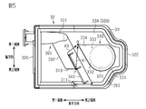
- the first distribution port 310 is arranged on the downstream side of the center of the downstream portion 302 in the extension direction. Further, the first distribution port 310 is open on the first end side in the longitudinal direction with respect to the central axis of the downstream portion 302. That is, as shown in FIG. 5, when the inner surface 33A of the top plate 32A of the upper lid 32 is viewed in a plan view, the first distribution port 310 opens toward the first end side in the longitudinal direction of the upper lid 32.
- the opening shape of the first distribution port 310 is a quadrangular shape in a plan view.
- a circular second distribution port 320 penetrates both main surfaces of the top plate 32A, that is, the inner surface 33A and the outer surface 33B.
- the second distribution port 320 is arranged on the upper lid 32 on the second end side in the longitudinal direction with respect to the flow pipe 300. Further, the second distribution port 320 is arranged substantially at the center in the width direction.
- the inner surface 33A of the top plate 32A is provided with an outlet baffle 330 as a first baffle that covers the second distribution port 320 from below.
- the outlet baffle 330 has a side wall 331 that rises from the inner surface 33A of the top plate 32A.
- the side wall 331 extends so as to surround the second distribution port 320 from three sides: the first end side in the longitudinal direction, the second end side in the longitudinal direction, and the second end side in the width direction.
- a baffle plate 332 substantially parallel to the inner surface 33A of the top plate 32A is connected to the tip of the side wall 331.
- the baffle plate 332 covers the entire second distribution port 320 when the upper lid 32 is viewed in a plan view from the inner surface 33A side.
- the side wall 331 of the outlet baffle 330 is not provided on the first end side in the width direction. Therefore, the outlet baffle 330 and the inner surface 33A of the top plate 32A in the upper lid 32 form the third distribution port 334.
- the third distribution port 334 is open toward the first end side in the width direction.
- the side wall 331 and the baffle plate 332 of the outlet baffle 330 and the inner surface 33A of the top plate 32A form an air passage 333 that communicates the third distribution port 334 and the second distribution port 320.
- the third distribution port 334 is open on the first end side in the width direction of the upper lid 32, while the first distribution port 310 is open on the first end side in the longitudinal direction of the upper lid 32. That is, the direction in which the first distribution port 310 opens and the direction in which the third distribution port 334 opens are different.
- a baffle 340 as a plate-shaped second baffle projects from the downstream portion 302 of the flow pipe 300 toward the inside of the water chamber 30.
- the baffle 340 is provided between the first distribution port 310 and the second distribution port 320 when the upper lid 32 is viewed from the inner surface 33A side in a plan view.
- the baffle 340 is arranged on the upper lid 32 on the second end side in the longitudinal direction with respect to the first distribution port 310, and extends along the opening edge of the first distribution port 310.
- the baffle 340 extends from the center of the downstream portion 302 in the extending direction to the downstream end of the downstream portion 302 in the axial direction of the downstream portion 302. As shown in FIG.
- the protruding tip extending toward the inside of the water chamber 30 of the baffle 340 is located below the lower end of the opening at the upstream end of the upstream portion 301 of the flow pipe 300.
- the water surface in the water chamber 30 is located at the lower end of the opening of the upstream portion 301 of the flow pipe 300. Therefore, when the water chamber 30 is full, the protruding tip of the baffle 340 is submerged in water.
- the water surface position when the water chamber 30 is full may be indicated by a scale or the like on the inner surface of the tank 31, for example.
- the shortest distance between the first distribution port 310 and the third distribution port 334 of the outlet baffle 330 is the second end side in the longitudinal direction and the width direction of the first distribution port 310. It is a path of arrow X1 connecting the opening end P of the first distribution port 310 on the first end side to the opening end Q on the first end side in the longitudinal direction of the third distribution port 334.
- the baffle 340 extends along the opening edge on the second end side in the longitudinal direction of the first distribution port 310. Then, it is arranged on the second end side in the longitudinal direction with respect to the downstream portion 302. Therefore, the baffle 340 is arranged on the shortest path between the first distribution port 310 and the third distribution port 334, and the baffle 340 extends in a direction intersecting the shortest path.
- a rubber sealing member 350 is attached to the inner surface 33A of the top plate 32A.
- the sealing member 350 extends along the outer edge shape of the top plate 32A.
- a portion of the flow pipe 300 near the downstream end of the downstream portion 302 becomes a curved portion 351 curved so as to be convex downward.
- the curved portion 351 is along the inner surface of the curved portion at the downstream end of the downstream portion 302.
- a plate-shaped plug 352 is arranged inside the curved portion 351.
- the plug body 352 has the same semicircular shape as the opening 311 in a plan view.
- the sealing member 350 is integrally molded as a whole.
- the sealing member 350 is removable from the inner surface 33A of the top plate 32A. Therefore, when the sealing member 350 is removed from the top plate 32A, the opening 311 of the downstream portion 302 is completely opened.
- a conduit 50 as a first pipe extends from the outer surface 33B of the upper lid 32 of the water chamber 30.
- the conduit 50 is connected to the opening edge of the second distribution port 320, and the inside of the conduit 50 communicates with the second distribution port 320.
- the conduit 50 extends obliquely toward the second end side in the width direction of the water chamber 30.
- the opening 51 on the side of the conduit 50 opposite to the second flow port 320 that is, the opening 51 on the downstream side faces the second end side in the width direction of the water chamber 30. That is, the opening 51 faces the side opposite to the third distribution port 334 with the central axis of the second distribution port 320 interposed therebetween.
- the conduit 50 is rotatable around the central axis of the second distribution port 320 as a rotation axis.
- the rotation range of the conduit 50 is within 90 degrees on both sides of the central axis of the second distribution port 320 with the direction opposite to the third distribution port 334 as the center. That is, the conduit 50 can rotate up to 90 degrees toward the first end side and the second end side in the longitudinal direction of the water chamber 30 with reference to the state of facing the second end side in the width direction of the water chamber 30. There is.
- the air pumped by the blower unit 100 flows into the water chamber 30 through the opening of the upstream portion 301 of the flow pipe 300.
- the air flowing into the flow pipe 300 is discharged between the upper lid 32 and the water surface of the water stored in the tank 31 through the first distribution port 310 of the downstream portion 302.
- the water stored in the tank 31 is heated by a heater or the like (not shown) arranged on the lower surface of the tank 31. Then, highly humid air accumulates near the surface of the water in the tank 31. Therefore, the air that has flowed into the tank 31 is mixed with the highly humid air and flows in the vicinity of the water surface of the water in the tank 31, so that the air is humidified.
- the humidified air in the water chamber 30 reaches the third distribution port 334 of the outlet baffle 330, it passes through the air passage 333 partitioned by the outlet baffle 330 and the inner surface 33A of the top plate 32A in the upper lid 32. It reaches the second distribution port 320.
- the air that has passed through the second distribution port 320 passes through the opening 51 of the conduit 50 and the inside of the air tube 90, and is supplied to the user 92 through the mask 91.
- the air discharged from the first distribution port 310 reaches the third distribution port 334 of the outlet baffle 330 through various paths in the water chamber 30.
- the third distribution port 334 is reached through a route that jumps over the baffle 340 from below.
- the tip of the baffle 340 is in contact with the water surface.
- the air discharged from the opening end P cannot jump over the baffle 340 and pass through as shown by the path of the arrow X2 in the figure. Therefore, it is conceivable that the air discharged from the opening end P reaches the third distribution port 334 by a route bypassing the baffle 340 as shown by the arrow X3 in the figure.
- the CPAP device 10 since the CPAP device 10 has a substantially rectangular parallelepiped shape that is longer in the longitudinal direction than in the width direction, it is relatively easy to roll over in the width direction. It is assumed that the CPAP device 10 rolls over so that the second end side of the CPAP device 10 in the width direction faces downward.
- the third distribution port 334 of the outlet baffle 330 faces upward. That is, except for the upper side of the second distribution port 320, the outlet baffle 330 is surrounded by the side wall 331. Further, when the humidifier 20 rolls over 90 degrees toward the second end side in the width direction, the opening of the upstream portion 301 of the flow pipe 300 is arranged on the upper side.
- the baffle 340 protrudes from the inner surface 33A of the top plate 32A of the upper lid 32.
- the baffle 340 is located on the shortest path between the third distribution port 334 and the first distribution port 310 of the outlet baffle 330 indicated by the arrow X1 in FIG. Further, the baffle 340 extends in a direction intersecting the shortest path. Therefore, the air discharged from the first distribution port 310 is blocked by the baffle 340 and cannot reach the third distribution port 334 by the shortest path. Therefore, for example, when the path of arrow X2 in FIG. 4 or the water chamber 30 is full, the path of arrow X3 is passed to reach the third distribution port 334.
- the first distribution port 310 opens on the first end side in the longitudinal direction of the upper lid 32
- the third distribution port 334 of the outlet baffle 330 opens on the first end side in the width direction of the upper lid 32. doing.
- the direction in which the first distribution port 310 opens and the direction in which the outlet baffle 330 opens intersect with each other, so that the air is easily agitated inside the tank 31. Therefore, the length of the flow path of the air flowing inside the water chamber 30 can be lengthened.
- a conduit 50 communicating with the second distribution port 320 extends from the outer surface 33B of the top plate 32A in the upper lid 32.
- the opening 51 of the conduit faces the second end side in the width direction of the humidifier 20. Therefore, when using the CPAP device 10, as shown in FIG. 1, the CPAP device 10 is often arranged so that the opening 51 of the conduit 50 and the user 92 face each other. When the user 92 moves in this arrangement, it is assumed that the humidifier 20 is pulled by the mask 91 and the air tube 90 attached to the user 92. That is, when the CPAP device 10 is used and the CPAP device 10 is tilted, it is conceivable that the CPAP device 10 is tilted toward the second end side in the width direction.
- the third distribution port 334 of the outlet baffle 330 faces upward and the upstream portion of the flow pipe 300.
- the opening of 301 is located on the upper side.
- the conduit 50 is 90 on the first end side and the second end side in the longitudinal direction of the water chamber 30, respectively, based on the state in which the conduit 50 faces the second end side in the width direction of the water chamber 30. It can rotate up to the degree. By rotating the conduit 50, the movable range of the air tube 90 is widened, and the humidifier 20 is less likely to fall even when the user 92 to which the mask 91 is attached moves. Further, since the conduit 50 has the above-mentioned movable range, the opening 51 of the conduit 50 does not face the first end side in the width direction of the water chamber 30.
- the CPAP device 10 it is difficult to use the CPAP device 10 in a state where the air tube 90 is extended from the first end side in the width direction of the CPAP device 10. In the used state, even if the CPAP device 10 rolls over, it is difficult for the CPAP device 10 to fall so that the first end side in the width direction faces downward. By preventing the CPAP device 10 from rolling over to the first end side in the width direction, it is possible to prevent the water in the tank 31 from flowing into the second distribution port 320 and leaking from the humidifier 20.
- the flow pipe 300 is curved, and the extension direction is different between the upstream portion 301 and the downstream portion 302.
- the opening on the upstream side of the flow pipe 300 is located near the edge on the first end side in the width direction, whereas the opening 311 on the downstream side of the flow pipe 300 is on the edge on the second end side in the width direction. It is located in the vicinity. Therefore, even if the water chamber 30 falls in the width direction, it is highly possible that either the upstream opening or the downstream opening 311 of the flow pipe 300 is located above the water surface in the tank 31. Therefore, when the water chamber 30 falls in the width direction, it is possible to prevent water from leaking through the flow pipe 300.
- a sealing member 350 is provided between the inner surface 33A of the top plate 32A of the upper lid 32 and the tank 31.
- the sealing member 350 is removable from the inner surface 33A of the upper lid 32.
- the upper lid 32 and the sealing member 350 can be cleaned by removing the sealing member 350.
- the sealing member 350 and the upper lid 32 can be disassembled and dried, and water is less likely to stay between the parts, which is hygienic.
- the flow pipe 400 penetrates the side wall 32B of the upper lid 32.
- the flow pipe 400 has a circular tubular shape on the outside of the water chamber 30, and a box shape that opens toward the inner surface 33A on the inside of the water chamber 30. Therefore, inside the water chamber 30, the air flow path is partitioned by the box-shaped inner surface of the flow pipe 400 and the inner surface 33A of the top plate 32A.
- the flow pipe 400 moves from the first end side in the longitudinal direction and the first end side in the width direction to the second end side in the longitudinal direction and the second end side in the width direction. It extends diagonally.
- the tip of the flow pipe 400 reaches the edge of the upper lid 32 on the second end side in the width direction.
- the tip of the flow pipe 400 is located substantially in the center of the upper lid 32 in the longitudinal direction.
- the flow path cross-sectional area of the flow pipe 400 gradually increases from the upstream side to the downstream side.
- the opening 411 is open at the downstream end of the flow pipe 400, that is, at the tip of the flow pipe 400 on the inner side of the water chamber 30. Further, in the flow pipe 400, the first distribution port 410 is opened separately from the opening 411.
- the first distribution port 410 is arranged on the downstream side of the center of the flow pipe 400 in the extension direction.
- the first distribution port 410 is arranged near the downstream end of the flow pipe 400.
- the first distribution port 410 is opened at the side wall on the first end side in the longitudinal direction of the flow pipe 400. That is, when the upper lid 32 is viewed in a plan view from the inner surface 33A side, the first distribution port 410 opens toward the first end side in the longitudinal direction and the second end side in the width direction diagonally.
- the opening shape of the first distribution port 410 is a quadrangular shape in a plan view.
- the baffle 440 protrudes from the flow pipe 400 toward the inside of the water chamber 30.
- the baffle 440 is composed of a plate-shaped main wall 441 and three auxiliary walls 442.
- the main wall 441 of the baffle 440 extends along the opening edge over the entire opening edge at the downstream end of the flow pipe 400.
- Three auxiliary walls 442 are connected to the main wall 441.
- the three auxiliary walls 442 are arranged on both sides and in the center of the main wall 441 in the extending direction.
- the auxiliary wall 442 extends from the main wall 441 toward the upstream side of the flow pipe 400.
- the auxiliary wall 442 extends longer than the opening range of the first distribution port 410. In other words, an auxiliary wall 442 exists in the entire area below the first distribution port 410.
- each auxiliary wall 442 becomes smaller toward the upstream side of the first distribution port 410.
- the water surface in the water chamber 30 is located at the lower end of the outer opening of the water chamber 30 of the flow pipe 400. Therefore, when the water chamber 30 is full, a part of the protruding tip of the main wall 441 of the baffle 440 and a part of the protruding tip of the auxiliary wall 442 are immersed in water.
- a circular second distribution port 420 penetrates both main surfaces of the top plate 32A, that is, the inner surface 33A and the outer surface 33B.
- the second distribution port 420 is arranged on the top plate 32A on the second end side in the longitudinal direction with respect to the flow pipe 400. Further, the second distribution port 420 is arranged substantially at the center in the width direction.
- a rubber sealing member 450 is attached to the inner surface 33A of the top plate 32A.
- the sealing member 450 includes an outer edge portion 451 extending along the outer edge shape of the top plate 32A.
- a protruding portion 452 projects toward the inside of the water chamber 30 at a position near the tip of the flow pipe 400.
- the protrusion length of the protrusion 452 is slightly larger than the vertical dimension of the opening 411.
- the protrusion 452 extends from the edge of the opening 411 on the second end side in the longitudinal direction toward the first end side in the longitudinal direction to a position approximately half of the opening 411.
- the protrusion 452 covers approximately half the area of the opening 411.
- the sealing member 450 includes a top plate portion 453 that extends along the inner surface 33A of the top plate 32A.
- the top plate portion 453 extends like a film on the second end side in the longitudinal direction from the flow pipe 400 in the top plate 32A.
- the top plate portion 453 has an opening penetrating so as not to block the second distribution port.
- the second end side in the longitudinal direction, the first end side in the width direction, and the second end side in the width direction of the top plate portion 453 are connected to the outer edge portion 451.
- a rubber outlet baffle 430 that covers the second distribution port 420 from below is provided in the vicinity of the second distribution port 420 in the top plate portion 453.
- the outlet baffle 430 is integrally molded with the top plate portion 453 of the sealing member 450.
- the outlet baffle 430 has a side wall 431 that rises from the inner surface of the top plate portion 453.
- the side wall 431 extends so as to surround the second distribution port 420 from three sides: the first end side in the longitudinal direction, the second end side in the longitudinal direction, and the second end side in the width direction.
- a baffle plate 432 substantially parallel to the inner surface 33A of the top plate 32A is connected to the tip of the side wall 431.
- baffle plate 432 on the first end side in the width direction protrudes beyond the extension range of the side wall 431.
- the baffle plate 432 covers the entire second distribution port 420 when the upper lid 32 is viewed in a plan view from the inner surface 33A side.
- the side wall 431 and the baffle plate 432 in the outlet baffle 430 and the top plate portion 453 along the inner surface 33A of the top plate 32A partition the air passage 433 communicating with the second distribution port 420.
- the side wall 431 of the outlet baffle 430 is not provided on the first end side in the width direction. Therefore, the third distribution port 434 of the air passage 433 opens toward the first end side in the width direction.
- the third distribution port 434 opens toward the first end side in the width direction of the upper lid 32, whereas the first distribution port 410 opens diagonally toward the first end side in the longitudinal direction and the second end side in the width direction. It is open. That is, the direction in which the first distribution port 410 opens and the direction in which the third distribution port 434 opens intersect.
- the auxiliary wall 442 exists in the entire area below the first distribution port 410.
- An auxiliary wall of the baffle 440 is on the straight path of the arrow Y1 connecting the opening end R on the second end side in the longitudinal direction of the first distribution port 410 to the opening end S on the first end side in the longitudinal direction of the third distribution port 434. 442 is arranged. That is, the auxiliary wall 442 of the baffle 440 extends in a direction intersecting the path of the arrow Y1.
- the sealing member 450 is removable from the inner surface 33A of the top plate 32A.
- the sealing member 450 and the outlet baffle 430 are integrally molded as a whole. Therefore, when the sealing member 450 is removed from the top plate 32A, the outlet baffle 430 is also removed from the top lid 32. Further, when the sealing member 450 is removed from the top plate 32A, the entire opening 411 at the tip of the flow pipe 400 becomes open.
- the air discharged from the first distribution port 410 reaches the third distribution port 434 of the outlet baffle 430 through various paths in the water chamber 30.
- the auxiliary wall 442 of the baffle 440 as shown by the arrow Y2 in the drawing is used. It is conceivable to reach the third distribution port 434 through a route that jumps from the lower side. Further, when water is stored in the water chamber 30 to a full state, a part of the tip of the auxiliary wall 442 is in contact with the water surface.
- the air discharged from the opening end R cannot jump over the baffle 440 and pass through as shown by the path of the arrow Y2 in the figure. Therefore, it is conceivable that the air discharged from the opening end R reaches the third distribution port 434 by a route bypassing the auxiliary wall 442 as shown by the arrow Y3 in the figure.
- the CPAP device 10 of the second embodiment has the following effects in addition to the effect of (1-2) of the first embodiment.
- the baffle 440 protrudes from the inner surface 33A of the top plate 32A in the upper lid 32 of the water chamber 30.
- the baffle 440 is located on the linear path connecting the opening end R and the opening end S indicated by the arrow Y1 in FIG. 7 among the linear paths connecting the third distribution port 434 and the first distribution port 410 of the outlet baffle 430.
- the baffle 340 extends in a direction intersecting the straight path indicated by the arrow Y1. Therefore, at least a part of the air discharged from the first distribution port 410 is blocked by the baffle 440 and cannot reach the third distribution port 434 by the shortest path. Therefore, for example, when the path of arrow Y2 in FIG.
- the path of arrow Y3 is passed to reach the third distribution port 434.
- These paths are longer than the paths of arrow X1 described above. Therefore, the air discharged into the water chamber 30 has a longer contact distance with the water surface in the water chamber 30, and is easily flowed to the downstream side together with the humid air. Therefore, the air discharged from the humidifier 20 is easily humidified.
- the outlet baffle 430 is integrally molded with the sealing member 450. Therefore, the outlet baffle 430 can be removed from the upper lid 32 together with the sealing member 450. By removing the outlet baffle 430 from the upper lid 32 when cleaning the upper lid 32, it is easy to visually recognize and clean the air passage 433 partitioned by the side wall 431, the baffle plate 432, and the top plate portion 453 of the outlet baffle 430.
- the CPAP device 10 may have any configuration as long as it has a blower unit 100 and a humidifier 20. Also, the shape of the CPAP device 10 is not limited. Further, as long as air can be supplied to and discharged from the humidifier 20, the humidifier 20 is not limited to the CPAP device 10.
- the humidifier 20 may have any configuration as long as it includes the water chamber 30.
- the conduit 50 may be omitted and the air tube 90 may be inserted into the second distribution port 320.
- a metal heat transfer member for improving heat conduction from the heater may be provided on the bottom surface of the water chamber 30.
- the shape of the humidifier 20 is not limited to the above embodiment.
- the configuration of the water chamber 30 is not limited.
- the tank 31 and the upper lid 32 may be integrally molded so that a part of the side surface of the tank 31 is opened.
- the upper lid 32 may not be provided with the first locking portion 32C or the second locking portion 32E, and the upper lid 32 may be attached to the tank 31 in a different configuration.
- both the upstream portion 301 and the downstream portion 302 may be formed in a tubular shape without a boundary.
- the opening directions of the first distribution ports 310 and 410 are not limited to the examples of the above embodiments. At least, the opening directions of the first distribution ports 310 and 410 may intersect with the opening directions of the third distribution ports 334 and 434 of the outlet baffles 330 and 430.
- the shapes of the second distribution ports 320 and 420 and the arrangement with respect to the upper lid 32 may be appropriately changed.
- the humidifier 20 rolls over so that the second end side in the width direction faces downward, and the width direction of the upper lid 32 is the second. It is preferably placed near the edge on one end side.
- the flow pipes 300 and 400 do not have to have a structure integrated with the upper lid 32.
- the flow pipes 300 and 400 may be tubular members penetrating on the side surface of the tank 31.
- the water chamber 30 may not be in contact with the upper lid 32, and air may flow through the flow pipes 300 and 400.
- the flow pipes 300 and 400 may be omitted, and the upper lid 32 may be provided with the first distribution ports 310 and 410.
- the shapes of the outlet baffles 330 and 430 may be changed as appropriate.
- the outlet baffles 330 and 430 may be hemispherical, and may have a shape that covers at least a part of the second distribution ports 320 and 420 from the lower side and partitions the inner surface of the upper lid 32 and the air passage.
- baffles 340 and 440 may be provided.
- the baffles 340 and 440 may be arranged so as to extend on the straight path between the first distribution ports 310 and 410 and the third distribution ports 334 and 434 and in the direction intersecting the straight path.
- the full state of the water chamber 30 may be arbitrarily set. Even in that case, it is preferable that the protruding tips of the baffles 340 and 440 are immersed in water when the water chamber 30 is full.
- the sealing member 350 may cover the entire inner surface 33A of the top plate 32A. Further, members such as baffles 340 and 440 may be integrally molded with the sealing members 350 and 450.
- a plurality of openings 311 and 411 may be provided. Further, openings 311 and 411 may be omitted.
- the shape of the conduit 50 is not limited to the above embodiment.
- the shape may be such that it protrudes from the outer surface 33B of the top plate 32A of the upper lid 32 and is curved so as to be parallel to the outer surface 33B of the top plate 32A of the upper lid 32 in the middle.
- the rotation range of the conduit 50 can be changed as appropriate.
- the conduit 50 may be rotatable 360 degrees. Further, the conduit 50 may not be rotatable. Further, the direction of the opening of the conduit 50 on the side opposite to the second distribution ports 320 and 420 can be changed as appropriate.
- the plug body 352 of the sealing member 350 may cover not the entire area of the opening 311 but a part thereof. Further, the plug body 352 itself may be omitted. Further, in the second embodiment, the protruding portion 452 may cover the entire area of the opening 411 or may be omitted.
- the sealing member 350 can be omitted.
- the sealing member 350 may be omitted if the upper lid 32 of the water chamber 30 itself is made of a soft material such as rubber.
Landscapes
- Health & Medical Sciences (AREA)
- Engineering & Computer Science (AREA)
- Life Sciences & Earth Sciences (AREA)
- Biomedical Technology (AREA)
- Veterinary Medicine (AREA)
- Public Health (AREA)
- Emergency Medicine (AREA)
- Pulmonology (AREA)
- Anesthesiology (AREA)
- General Health & Medical Sciences (AREA)
- Heart & Thoracic Surgery (AREA)
- Hematology (AREA)
- Animal Behavior & Ethology (AREA)
- Chemical & Material Sciences (AREA)
- Mechanical Engineering (AREA)
- Combustion & Propulsion (AREA)
- General Engineering & Computer Science (AREA)
- Air Humidification (AREA)
Priority Applications (3)
| Application Number | Priority Date | Filing Date | Title |
|---|---|---|---|
| JP2022514411A JP7347657B2 (ja) | 2020-04-08 | 2021-03-26 | 加湿器 |
| US17/938,498 US12329911B2 (en) | 2020-04-08 | 2022-10-06 | Humidifier |
| JP2023144156A JP7495001B2 (ja) | 2020-04-08 | 2023-09-06 | 加湿器 |
Applications Claiming Priority (2)
| Application Number | Priority Date | Filing Date | Title |
|---|---|---|---|
| JP2020069629 | 2020-04-08 | ||
| JP2020-069629 | 2020-04-08 |
Related Child Applications (1)
| Application Number | Title | Priority Date | Filing Date |
|---|---|---|---|
| US17/938,498 Continuation US12329911B2 (en) | 2020-04-08 | 2022-10-06 | Humidifier |
Publications (1)
| Publication Number | Publication Date |
|---|---|
| WO2021205913A1 true WO2021205913A1 (ja) | 2021-10-14 |
Family
ID=78023316
Family Applications (1)
| Application Number | Title | Priority Date | Filing Date |
|---|---|---|---|
| PCT/JP2021/013010 Ceased WO2021205913A1 (ja) | 2020-04-08 | 2021-03-26 | 加湿器 |
Country Status (3)
| Country | Link |
|---|---|
| US (1) | US12329911B2 (https=) |
| JP (2) | JP7347657B2 (https=) |
| WO (1) | WO2021205913A1 (https=) |
Cited By (3)
| Publication number | Priority date | Publication date | Assignee | Title |
|---|---|---|---|---|
| JP2023159636A (ja) * | 2022-04-20 | 2023-11-01 | 株式会社村田製作所 | Cpap装置 |
| JP2023159637A (ja) * | 2022-04-20 | 2023-11-01 | 株式会社村田製作所 | Cpap装置 |
| JP2023159635A (ja) * | 2022-04-20 | 2023-11-01 | 株式会社村田製作所 | Cpap装置 |
Citations (6)
| Publication number | Priority date | Publication date | Assignee | Title |
|---|---|---|---|---|
| JP2004524087A (ja) * | 2001-02-16 | 2004-08-12 | レスメッド・リミテッド | 加湿器入口を介しての液の逆流を防ぐ構造を有する加湿器 |
| JP2009504278A (ja) * | 2005-08-15 | 2009-02-05 | レスメド・リミテッド | Cpap装置用加湿器槽 |
| EP3045198A1 (en) * | 2014-01-08 | 2016-07-20 | BMC Medical Co., Ltd. | Humidifier for respirator and respirator |
| JP2018064972A (ja) * | 2012-09-07 | 2018-04-26 | フィッシャー アンド ペイケル ヘルスケア リミテッド | 呼吸補助装置のための加湿チャンバ |
| EP3508241A1 (en) * | 2016-08-31 | 2019-07-10 | BMC Medical Co., Ltd. | Air-guiding tube component, liquid-storage device, humidifier, and ventilator |
| US20200101259A1 (en) * | 2018-09-28 | 2020-04-02 | Koninklijke Philips N.V. | Humidifier with ingress protection for use in cpap therapy |
Family Cites Families (8)
| Publication number | Priority date | Publication date | Assignee | Title |
|---|---|---|---|---|
| US5598837A (en) * | 1995-06-06 | 1997-02-04 | Respironics, Inc. | Passive humidifier for positive airway pressure devices |
| US6398197B1 (en) | 1999-05-10 | 2002-06-04 | Fisher & Paykel Limited | Water chamber |
| US6827340B2 (en) * | 2000-08-14 | 2004-12-07 | Taga Medical Technologies, Inc. | CPAP humidifier |
| CN1304068C (zh) | 2001-02-16 | 2007-03-14 | 雷斯梅德有限公司 | 治疗睡眠呼吸紊乱装置中的气压信号监测 |
| DE10226160B4 (de) | 2002-06-12 | 2009-06-18 | Hoffrichter Gmbh | Luftbefeuchter für ein Beatmungsgerät |
| AU2004266551B2 (en) * | 2003-08-20 | 2009-07-23 | Fisher & Paykel Healthcare Limited | Water chamber for humidifier |
| JP5824740B2 (ja) * | 2007-06-04 | 2015-11-25 | コンピュメディクス メディカル イノベーション ピーティーワイ リミテッド | 貯水槽バッフル |
| US10806877B2 (en) * | 2015-03-24 | 2020-10-20 | Micomme Medical Technology Development Co., Ltd. | Portable breathing machine |
-
2021
- 2021-03-26 WO PCT/JP2021/013010 patent/WO2021205913A1/ja not_active Ceased
- 2021-03-26 JP JP2022514411A patent/JP7347657B2/ja active Active
-
2022
- 2022-10-06 US US17/938,498 patent/US12329911B2/en active Active
-
2023
- 2023-09-06 JP JP2023144156A patent/JP7495001B2/ja active Active
Patent Citations (6)
| Publication number | Priority date | Publication date | Assignee | Title |
|---|---|---|---|---|
| JP2004524087A (ja) * | 2001-02-16 | 2004-08-12 | レスメッド・リミテッド | 加湿器入口を介しての液の逆流を防ぐ構造を有する加湿器 |
| JP2009504278A (ja) * | 2005-08-15 | 2009-02-05 | レスメド・リミテッド | Cpap装置用加湿器槽 |
| JP2018064972A (ja) * | 2012-09-07 | 2018-04-26 | フィッシャー アンド ペイケル ヘルスケア リミテッド | 呼吸補助装置のための加湿チャンバ |
| EP3045198A1 (en) * | 2014-01-08 | 2016-07-20 | BMC Medical Co., Ltd. | Humidifier for respirator and respirator |
| EP3508241A1 (en) * | 2016-08-31 | 2019-07-10 | BMC Medical Co., Ltd. | Air-guiding tube component, liquid-storage device, humidifier, and ventilator |
| US20200101259A1 (en) * | 2018-09-28 | 2020-04-02 | Koninklijke Philips N.V. | Humidifier with ingress protection for use in cpap therapy |
Cited By (9)
| Publication number | Priority date | Publication date | Assignee | Title |
|---|---|---|---|---|
| JP2023159636A (ja) * | 2022-04-20 | 2023-11-01 | 株式会社村田製作所 | Cpap装置 |
| JP2023159637A (ja) * | 2022-04-20 | 2023-11-01 | 株式会社村田製作所 | Cpap装置 |
| JP2023159635A (ja) * | 2022-04-20 | 2023-11-01 | 株式会社村田製作所 | Cpap装置 |
| JP7528978B2 (ja) | 2022-04-20 | 2024-08-06 | 株式会社村田製作所 | Cpap装置 |
| JP7533522B2 (ja) | 2022-04-20 | 2024-08-14 | 株式会社村田製作所 | Cpap装置 |
| JP2024133374A (ja) * | 2022-04-20 | 2024-10-01 | 株式会社村田製作所 | Cpap装置 |
| JP2024138197A (ja) * | 2022-04-20 | 2024-10-07 | 株式会社村田製作所 | Cpap装置 |
| JP7609120B2 (ja) | 2022-04-20 | 2025-01-07 | 株式会社村田製作所 | Cpap装置 |
| US12605522B2 (en) | 2022-04-20 | 2026-04-21 | Murata Manufacturing Co., Ltd. | CPAP apparatus |
Also Published As
| Publication number | Publication date |
|---|---|
| JPWO2021205913A1 (https=) | 2021-10-14 |
| JP7495001B2 (ja) | 2024-06-04 |
| US12329911B2 (en) | 2025-06-17 |
| JP2023164512A (ja) | 2023-11-10 |
| US20230030885A1 (en) | 2023-02-02 |
| JP7347657B2 (ja) | 2023-09-20 |
Similar Documents
| Publication | Publication Date | Title |
|---|---|---|
| JP7495001B2 (ja) | 加湿器 | |
| KR20180044568A (ko) | 가습겸용 공기청정기 | |
| KR20180002680U (ko) | 응축수를 제거할 수 있는 전열교환기 | |
| CN217209762U (zh) | 加湿器的湿帘结构 | |
| KR20180115120A (ko) | 가습 및 제습 겸용 장치 | |
| JP6028218B2 (ja) | 加湿装置 | |
| JP4069915B2 (ja) | 加湿器 | |
| JP7609120B2 (ja) | Cpap装置 | |
| KR20200043743A (ko) | 가습 공기청정기 | |
| JP7219178B2 (ja) | 加湿装置 | |
| JP7528978B2 (ja) | Cpap装置 | |
| CN221513188U (zh) | 一种湿化罐及使用其的呼吸机 | |
| JP2008025898A (ja) | 加湿機能付空気清浄機 | |
| JP7533522B2 (ja) | Cpap装置 | |
| JP5810261B2 (ja) | 加湿装置 | |
| JP2015161413A (ja) | 空気調和装置 | |
| CN116428662B (zh) | 加湿组件及空调机组 | |
| CN217685599U (zh) | 一种加湿风扇 | |
| JP7253682B2 (ja) | 加湿ユニット | |
| JP2019100639A (ja) | 加湿送風ユニット | |
| KR20180002681U (ko) | 응축수를 제거할 수 있는 전열교환기 | |
| JP4877216B2 (ja) | 髪ケア装置 | |
| JP2013204954A (ja) | 加湿装置 | |
| JP5434834B2 (ja) | 小型加湿機 | |
| JP2023044438A (ja) | 暖房装置 |
Legal Events
| Date | Code | Title | Description |
|---|---|---|---|
| 121 | Ep: the epo has been informed by wipo that ep was designated in this application |
Ref document number: 21784334 Country of ref document: EP Kind code of ref document: A1 |
|
| ENP | Entry into the national phase |
Ref document number: 2022514411 Country of ref document: JP Kind code of ref document: A |
|
| NENP | Non-entry into the national phase |
Ref country code: DE |
|
| 122 | Ep: pct application non-entry in european phase |
Ref document number: 21784334 Country of ref document: EP Kind code of ref document: A1 |