WO2021200923A1 - 熱間プレス装置及び熱間プレス成形品の製造方法 - Google Patents
熱間プレス装置及び熱間プレス成形品の製造方法 Download PDFInfo
- Publication number
- WO2021200923A1 WO2021200923A1 PCT/JP2021/013497 JP2021013497W WO2021200923A1 WO 2021200923 A1 WO2021200923 A1 WO 2021200923A1 JP 2021013497 W JP2021013497 W JP 2021013497W WO 2021200923 A1 WO2021200923 A1 WO 2021200923A1
- Authority
- WO
- WIPO (PCT)
- Prior art keywords
- metal plate
- mold
- contact
- bottom dead
- movable
- Prior art date
- Legal status (The legal status is an assumption and is not a legal conclusion. Google has not performed a legal analysis and makes no representation as to the accuracy of the status listed.)
- Ceased
Links
Images




Classifications
-
- B—PERFORMING OPERATIONS; TRANSPORTING
- B21—MECHANICAL METAL-WORKING WITHOUT ESSENTIALLY REMOVING MATERIAL; PUNCHING METAL
- B21D—WORKING OR PROCESSING OF SHEET METAL OR METAL TUBES, RODS OR PROFILES WITHOUT ESSENTIALLY REMOVING MATERIAL; PUNCHING METAL
- B21D22/00—Shaping without cutting, by stamping, spinning, or deep-drawing
- B21D22/20—Deep-drawing
-
- B—PERFORMING OPERATIONS; TRANSPORTING
- B21—MECHANICAL METAL-WORKING WITHOUT ESSENTIALLY REMOVING MATERIAL; PUNCHING METAL
- B21D—WORKING OR PROCESSING OF SHEET METAL OR METAL TUBES, RODS OR PROFILES WITHOUT ESSENTIALLY REMOVING MATERIAL; PUNCHING METAL
- B21D22/00—Shaping without cutting, by stamping, spinning, or deep-drawing
- B21D22/02—Stamping using rigid devices or tools
- B21D22/06—Stamping using rigid devices or tools having relatively-movable die parts
-
- B—PERFORMING OPERATIONS; TRANSPORTING
- B21—MECHANICAL METAL-WORKING WITHOUT ESSENTIALLY REMOVING MATERIAL; PUNCHING METAL
- B21D—WORKING OR PROCESSING OF SHEET METAL OR METAL TUBES, RODS OR PROFILES WITHOUT ESSENTIALLY REMOVING MATERIAL; PUNCHING METAL
- B21D22/00—Shaping without cutting, by stamping, spinning, or deep-drawing
- B21D22/20—Deep-drawing
- B21D22/208—Deep-drawing by heating the blank or deep-drawing associated with heat treatment
-
- B—PERFORMING OPERATIONS; TRANSPORTING
- B21—MECHANICAL METAL-WORKING WITHOUT ESSENTIALLY REMOVING MATERIAL; PUNCHING METAL
- B21D—WORKING OR PROCESSING OF SHEET METAL OR METAL TUBES, RODS OR PROFILES WITHOUT ESSENTIALLY REMOVING MATERIAL; PUNCHING METAL
- B21D22/00—Shaping without cutting, by stamping, spinning, or deep-drawing
- B21D22/20—Deep-drawing
- B21D22/22—Deep-drawing with devices for holding the edge of the blanks
-
- B—PERFORMING OPERATIONS; TRANSPORTING
- B21—MECHANICAL METAL-WORKING WITHOUT ESSENTIALLY REMOVING MATERIAL; PUNCHING METAL
- B21D—WORKING OR PROCESSING OF SHEET METAL OR METAL TUBES, RODS OR PROFILES WITHOUT ESSENTIALLY REMOVING MATERIAL; PUNCHING METAL
- B21D24/00—Special deep-drawing arrangements in, or in connection with, presses
- B21D24/04—Blank holders; Mounting means therefor
-
- B—PERFORMING OPERATIONS; TRANSPORTING
- B21—MECHANICAL METAL-WORKING WITHOUT ESSENTIALLY REMOVING MATERIAL; PUNCHING METAL
- B21D—WORKING OR PROCESSING OF SHEET METAL OR METAL TUBES, RODS OR PROFILES WITHOUT ESSENTIALLY REMOVING MATERIAL; PUNCHING METAL
- B21D24/00—Special deep-drawing arrangements in, or in connection with, presses
- B21D24/10—Devices controlling or operating blank holders independently, or in conjunction with dies
- B21D24/14—Devices controlling or operating blank holders independently, or in conjunction with dies pneumatically or hydraulically
-
- B—PERFORMING OPERATIONS; TRANSPORTING
- B21—MECHANICAL METAL-WORKING WITHOUT ESSENTIALLY REMOVING MATERIAL; PUNCHING METAL
- B21D—WORKING OR PROCESSING OF SHEET METAL OR METAL TUBES, RODS OR PROFILES WITHOUT ESSENTIALLY REMOVING MATERIAL; PUNCHING METAL
- B21D53/00—Making other particular articles
- B21D53/88—Making other particular articles other parts for vehicles, e.g. cowlings, mudguards
-
- B—PERFORMING OPERATIONS; TRANSPORTING
- B30—PRESSES
- B30B—PRESSES IN GENERAL
- B30B15/00—Details of, or accessories for, presses; Auxiliary measures in connection with pressing
- B30B15/28—Arrangements for preventing distortion of, or damage to, presses or parts thereof
- B30B15/281—Arrangements for preventing distortion of, or damage to, presses or parts thereof overload limiting devices
Definitions
- the present invention relates to a hot press device and a method for manufacturing a hot press molded product.
- characteristics such as strength may be changed locally. For example, when a high-strength member is applied to a vehicle skeleton member, the strength of a specific part may be reduced instead of increasing the strength of all parts of the member. There are several reasons for this. For example, processing such as drilling may be performed in a low-strength portion. Further, in another case, when the member is deformed, the low-strength portion may be deformed at an early stage to control the deformation behavior.
- One of the methods for manufacturing a member having a low-strength part is a method of hot stamping a tailored blank (Tailor-Welded Blank) obtained by welding steel materials having different characteristics.
- a tailored blank Teilor-Welded Blank
- Japanese Patent No. 5864414 describes a method of hot press forming a steel sheet blank composed of separate plates welded together.
- a heated steel sheet blank is hot press formed in a cooled tool pair and the formed product is cured while the blank is still in the tool pair.
- the weld between the two plates is cooled at a reduced cooling rate in relation to both sides of the weld.
- a portion having a low martensite content is formed along the welded portion.
- the cooling rate is reduced by maintaining a gap between the tool pair and the final product.
- Japanese Patent Application Laid-Open No. 2015-226936 discloses a manufacturing method that enables local adjustment of the structure of a metal structure component.
- the steel member is hot formed and hardened by contact with the tool surface over at least several sections. At least one of the two sections of the tool surface has a surface coating that reduces or increases thermal conductivity.
- the sections of the tool surface that have different thermal conductivity cause different cooling rates. Subregions of steel members with different cooling rates will have different microstructures after curing.
- the cooling rate of the metal plate can be partially reduced by the gap (clearance) between the molded product and the mold or the distribution of the thermal conductivity on the surface of the mold.
- the temperature of the portion where the cooling rate is slow is high. After that, the portion may be thermally shrunk with cooling, which may cause a shape defect in the molded product.
- the temperature difference in the molded product is large when the molded product is taken out from the mold, the molded product may be deformed due to heat shrinkage, resulting in a shape defect.
- the molded product In order to reduce the temperature of the molded product when it is taken out from the mold and the temperature difference in the molded product, the molded product must be held in the mold until the temperature in the molded product becomes uniform. On the other hand, from the viewpoint of manufacturing cost and the like, it is preferable that the holding time (bottom dead center holding time) of the molded product by the mold is short. That is, it is difficult to achieve both productivity and shape accuracy by the conventional method.
- the present disclosure discloses a hot press device capable of ensuring the shape accuracy of a molded product having a characteristic distribution without lengthening the bottom dead center holding time of the molded product by a die in a hot press.
- a method for manufacturing a hot press molded product is provided.
- the hot press device includes a first die, a second die that can move relative to the first die in the pressing direction, the first die, and the second die. It is provided with a control unit for controlling the relative movement of the. At least one of the first mold and the second mold has a recess on a surface facing the other mold in the pressing direction. A movable mold that is movable in a direction intersecting the facing surface is arranged in the recess.
- a heated and press-formed metal plate is held between the first mold and the second mold, and the first mold and the second mold are at the bottom dead point.
- the movable mold is controlled so that the bottom dead point holding period includes a contact period in which the movable mold abuts on the metal plate and a non-contact period in which the movable mold does not abut on the metal plate. do.
- the shape accuracy of a molded product with a characteristic distribution can be ensured without lengthening the bottom dead center holding time of the molded product by the die.
- FIG. 1 is a cross-sectional view showing a configuration example of a press device according to the present embodiment.
- FIG. 2 is a diagram showing a state at the bottom dead center of the press device shown in FIG.
- FIG. 3 is a diagram showing a state in which the movable mold 4 abuts on the metal plate B at the bottom dead center.
- FIG. 4 is a graph showing an example when there is a contact period at the beginning of the bottom dead center holding period.
- FIG. 5 is a graph showing an example when there is a contact period at the end of the bottom dead center holding period.
- FIG. 6 is a diagram showing a modified example of the configuration of the clearance portion.
- FIG. 7 is a diagram showing another modified example of the configuration of the clearance portion.
- FIG. 1 is a cross-sectional view showing a configuration example of a press device according to the present embodiment.
- FIG. 2 is a diagram showing a state at the bottom dead center of the press device shown in FIG.
- FIG. 3 is
- FIG. 8 is a diagram showing a modified example of the movable mold 4.
- FIG. 9 is a diagram showing another modified example of the configuration of the clearance portion.
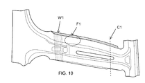
- FIG. 10 is a diagram showing evaluation positions of shape accuracy in the molded product of this embodiment.
- FIG. 11 is a graph showing the result of hardness distribution of the molded product.
- FIG. 12 is a graph showing the result of the twist angle of the molded product.
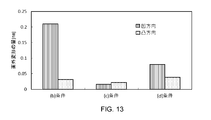
- FIG. 13 is a graph showing the result of out-of-plane deformation of the molded product.
- the hot press device includes a first die, a second die that can move relative to the first die in the pressing direction, the first die, and the second die. It is provided with a control unit for controlling the relative movement of the. At least one of the first mold and the second mold has a recess on a surface facing the other mold in the pressing direction. A movable mold that is movable in a direction intersecting the facing surfaces is arranged in the recess.
- a heated and press-molded metal plate is held between the first mold and the second mold, and the first mold and the second mold are at the bottom dead point.
- the contact period is located at the contact position where the movable mold is in contact with the metal plate, and the non-contact period is located at the retracted position where the movable mold does not contact the metal plate.
- the position of the movable mold is controlled so as to include.
- the cooling rate can be slowed, that is, slow cooling can be performed in the bottom dead center holding period and in the non-contact period in which the movable mold does not abut on the metal plate. Further, the cooling rate can be increased, that is, rapid cooling can be performed during the contact period in which the movable mold having the bottom dead center holding time abuts on the metal plate. As a result, the temperature distribution of the metal plate can be made uniform while the cooling conditions of the portion of the molded metal plate in contact with the movable mold are different from those of the other portions.
- the metal plate after molding taken out from the mold is given a characteristic distribution due to the difference in cooling conditions, and the deterioration of the shape accuracy of the molded product due to the temperature difference can be suppressed. In this way, the shape accuracy of the molded product to which the characteristic distribution is given can be ensured without lengthening the bottom dead center holding time of the molded product by the mold.
- the cooling condition when a part of the member is slowly cooled is a predetermined cooling condition based on the mold configuration. Therefore, the metal structure obtained by slow cooling and the temperature distribution state of the members taken out from the mold also depend on the mold configuration. In order to change these, it is necessary to modify or remanufacture the mold configuration.
- the cooling condition can be controlled by adjusting the length of the contact period in the bottom dead center holding period. Therefore, in the press working using the hot press device, the cooling conditions when a part of the formed metal plate is slowly cooled can be easily changed.
- the movable mold is configured to be movable between the contact position and the retracted position.
- the control unit switches the movable mold between the contact position and the retracted position during the bottom dead center holding period.
- the contact surface of the movable mold with the metal plate is at a position corresponding to the molding surface.
- the movable mold is in the retracted position, the movable mold is retracted into the recess and is separated from the molding surface.
- the retracted position is set to a position where the metal plate does not come into contact with the movable mold even when the portion corresponding to the recess of the metal plate is deformed out of the plane at the bottom dead center, for example.
- the retracting position is determined according to, for example, at least one of the area of the recess and the thickness of the metal plate to be processed.
- the control unit brings the movable mold into contact with the metal plate at the beginning of the bottom dead center holding period, and then attaches the movable mold to the metal at the end of the bottom dead center holding period. It may be separated from the board. That is, the control unit may move the movable mold from the contact position to the retracted position within the bottom dead center holding period.
- the metal plate can be molded by the movable mold at a time when the temperature of the metal plate is relatively high and it is easy to mold during the bottom dead center holding period. Therefore, it is easy to secure the local shape accuracy of the portion corresponding to the movable mold of the molded metal plate.
- the control unit separates the movable mold from the metal plate at the beginning of the bottom dead center holding period, and then separates the movable mold from the metal plate at the end of the bottom dead center holding period. May be brought into contact with. That is, the control unit may move the movable mold from the retracted position to the contact position within the bottom dead center holding period. As a result, the movable mold can be brought into contact with the metal plate and rapidly cooled when the temperature of the metal plate is relatively low during the bottom dead center holding period. Therefore, the temperature distribution of the metal plate can be easily made uniform. Therefore, it is easy to secure the shape accuracy of the formed metal plate as a whole. In addition, it becomes easy to adjust the cooling conditions by controlling the contact period.
- the control unit abuts the movable mold on the metal plate at the beginning of the bottom dead center holding period, then separates the movable mold, and again at the end of the bottom dead center holding period.
- the mold may be brought into contact with the metal plate. That is, the control unit may move the movable mold from the contact position to the retracted position and then move it to the contact position again within the bottom dead center holding period.
- the movable mold can be rapidly cooled during the relatively high and low bottom dead center retention periods. Therefore, it becomes easy to control the shape accuracy.
- the control unit may control the movable mold so that the contact period is 10 to 90% of the entire bottom dead center holding period, for example.
- the contact period is preferably 80% or less, more preferably 70% or less, and further preferably 50% or less of the entire bottom dead center holding period.
- the control unit may control the movable mold so that the non-contact period is 10% or more of the entire bottom dead center holding period.
- the recess may include a first recess of the first mold and a second recess of the second mold at a position facing the first recess. ..
- the movable mold is arranged in at least one of the first recess and the second recess facing each other.
- the movable molds may be arranged in both the first recess and the second recess facing each other. As a result, the robustness of the cooling conditions can be further enhanced.
- the movable mold is arranged on the surface of the movable mold in contact with the metal plate in a state where the movable mold is in contact with the metal plate at the bottom dead center. It may be formed so as to be arranged on the same surface as the surface of the mold around the recessed portion. As a result, the characteristic distribution can be imparted to the flat portion of the molded metal plate.
- the top surface of the movable mold has a convex portion that contacts the metal plate in a state where the movable mold is in contact with the metal plate at the bottom dead center. It may have a recess that does not abut. Even during the contact period in which the movable mold is in contact with the metal plate, there is a clearance in the recess of the movable mold. As a result, slow cooling is possible. Further, the cooling conditions can be changed by changing the shapes of the convex portion and the concave portion on the top surface of the movable mold.
- the top surface of the movable mold is the end surface of both end faces in the concave portion of the movable mold in the moving direction, which is closer to the position where the metal plate is arranged.
- the top surface of the movable die of one of the first die and the second die may have irregularities protruding or denting in the pressing direction.
- the facing surface of the one movable die and the other mold or the movable die facing the pressing direction may have a shape corresponding to the unevenness of the top surface of the one movable die.
- the facing surface of the other mold or the movable mold may also be configured to be in contact with the metal plate.
- the metal plate can be formed into a shape corresponding to the uneven shape of the movable mold.
- the control unit may adjust the distance between the metal plate and the movable mold at the retracted position of the movable mold. Thereby, in the retracted position, an appropriate retracted position can be set so that the metal plate and the movable mold are less likely to come into contact with each other. At bottom dead center, the portion of the metal plate corresponding to the recess may be out-of-plane deformation. The degree of this out-of-plane deformation varies depending on the area of the recess and the thickness of the metal plate.
- control unit adjusts the retracted position of the movable mold according to the thickness of the metal plate, so that the metal plate deformed out of plane at the bottom dead center comes into contact with the movable mold in the retracted position. Can be less likely to occur.
- the hot press device may include a cooling mechanism for cooling the first die and the second die.
- a cooling mechanism for cooling the first die and the second die.
- at least one of the first mold and the second mold may have a pipe or a groove for passing a cooling medium.
- the method for producing a hot press molded product according to the embodiment of the present invention includes a step of arranging a heated metal plate between the first mold and the second mold, and the first mold and the second mold.
- the step of moving the movable mold provided in at least one recess of the first mold and the second mold with respect to the metal plate is performed.
- the bottom dead center holding period includes a contact period in which the movable mold abuts on the metal plate and a non-contact period in which the movable mold does not abut on the metal plate. Includes period.
- the cooling rate can be slowed down during the non-contact period of the bottom dead center holding period.
- the cooling rate can be increased during the contact period of the bottom dead center holding time.
- Manufacturing method 2 In the manufacturing method 1, the movable mold abuts on the metal plate at the beginning of the bottom dead center holding period, and then the movable mold separates from the metal plate at the end of the bottom dead center holding period. May be good. That is, the movable mold may be controlled to move from the contact position to the retracted position within the bottom dead center holding period.
- the movable mold is separated from the metal plate at the beginning of the bottom dead center holding period, and then the movable mold comes into contact with the metal plate at the end of the bottom dead center holding period. May be good. That is, the movable mold may be controlled to move from the retracted position to the contact position within the bottom dead center holding period.
- Manufacturing method 4 In any of the manufacturing methods 1 to 3, when the movable mold is in contact with the metal plate at the bottom dead point, the surface of the movable mold in contact with the metal plate is formed by the movable mold. It may be arranged on the same surface as the surface of the mold in contact with the metal plate around the arranged recess.
- the top surface of the movable mold has a convex portion that contacts the metal plate in a state where the movable mold is in contact with the metal plate at the bottom dead center. It may have a recess that does not abut.
- the top surface of one of the first mold and the second mold may have irregularities protruding or denting in the pressing direction.
- the facing surface of the one movable die and the other mold or the movable die facing the pressing direction may have a shape corresponding to the unevenness of the top surface of the one movable die. While the one movable mold is in contact with the metal plate at the bottom dead center, the facing surface of the other mold or the movable mold may also be in contact with the metal plate.
- the movable mold may be controlled so that the non-contact period is 10% or more of the entire bottom dead center holding period.
- An embodiment of the present invention also includes a method of manufacturing a hot press molded product by any of the above manufacturing methods 1 to 6 using the hot press apparatus of any of the above configurations 1 to 9.
- FIG. 1 is a cross-sectional view showing a configuration example of a hot press device according to the present embodiment.
- FIG. 2 is a diagram showing a state in which the die of the hot press device shown in FIG. 1 is at bottom dead center.
- the hot press device 1 press-molds the metal plate B into a press-molded product.
- the hot press device 1 includes a die 2, a punch 3, a die pad 5, a movable die 4, and a control unit 9 as dies.
- the die 2 can move in the press direction PD with respect to the punch 3. That is, the die 2 and the punch 3 can move relative to each other. The direction of this relative movement is the pressing direction.
- the die 2 can be moved in the pressing direction with respect to the punch 3 by the elevating mechanism (actuator) 8.
- the elevating mechanism 8 may include, for example, a hydraulic cylinder, an air cylinder, an air cushion, or a cam.
- the die 2 moves with respect to the punch 3, but the punch 3 may be configured to move with respect to the die 2.
- both the die 2 and the punch 3 may be configured to move.
- the hot press device 1 arranges the metal plate B between the die 2 and the punch 3, and presses the metal plate B from both the die 2 and the punch 3 to press-mold the metal plate B.
- the die 2 and the punch 3 are examples of the first mold and the second mold.
- the die 2 has a concave shape on the inside corresponding to the shape of the press-molded product.
- the punch 3 has a convex shape corresponding to the concave shape of the die 2.
- the surface of the die 2 facing the punch 3 includes a pressure surface that is in contact with the metal plate B and pressurizes.
- the surface of the die 2 facing the punch 3 has a recess 2a.
- the recess 2a does not come into contact with the metal plate B even at bottom dead center. That is, the recess 2a serves as a clearance with the metal plate B at the bottom dead center (see FIG. 2).
- the die pad 5 is movable in the pressing direction with respect to the die 2 via an elevating mechanism 6 such as a hydraulic cylinder.
- the die pad 5 can move in the vertical direction together with the punch 3 in a state where the top surface is pressed against the metal plate B.
- the die pad 5 is provided at a position facing the top surface of the punch 3.
- the top surface of the die pad 5 and the top surface of the punch 3 face each other in the pressing direction.
- the die pad 5 may be omitted.
- the surface of the punch 3 facing the die 2 includes a pressure surface that is in contact with the metal plate B and pressurizes.
- the surface of the punch 3 facing the die 2 has a recess 3a.
- a movable mold 4 is arranged in the recess 3a.
- the recess 3a of the punch 3 is located at a position facing the recess 2a of the die 2 in the pressing direction. That is, when viewed from the pressing direction, at least a part of the recess 3a of the punch 3 overlaps with the recess 2a of the die 2.
- the movable mold 4 is provided in the recess 3a of the punch 3 and can move with respect to the punch 3 in a direction intersecting the surface of the punch 3 facing the die 2.
- the movable mold 4 is movable in the depth direction of the recess 3a by the elevating mechanism (actuator) 7.
- the elevating mechanism (actuator) 7 In the example shown in FIG. 1, the movable die 4 may be pushed into the recess 3a of the punch 3. That is, the top surface of the movable mold 4 can be inserted deeper into the recess 3a than the edge of the opening of the recess 3a. In the example shown in FIG. 2, at the bottom dead center, the top surface 4u of the movable mold 4 is withdrawn into the recess 3a.
- the movable mold 4 does not come into contact with the metal plate B between the die 2 and the punch 3. In this way, the movable mold 4 is movable between the position where the metal plate B held at the bottom dead center is in contact with the metal plate B, that is, the contact position, and the position where there is a clearance between the metal plate B, that is, the retracted position. It is composed.
- the movable die 4 can move in the press direction, but the moving direction of the movable die 4 is not limited to the press direction.
- the elevating mechanism 7 can be composed of, for example, a hydraulic cylinder, an air cylinder, a cam, or a gas cushion.
- FIG. 3 is a diagram showing a state in which the movable mold 4 abuts on the metal plate B at the bottom dead center.
- the movable mold 4 can be moved from the state of being inserted into the recess 3a until at least the top surface 4u of the movable mold 4 is at the same height as the pressure surface 3u around the recess 3a. ..
- the top surface 4u of the movable mold 4 has a shape that can be positioned on the same surface as the pressure surface 3u around the recess 3a. The entire top surface 4u of the movable mold 4 comes into contact with the metal plate B.
- the control unit 9 controls the die 2, the punch 3, and the movable mold 4. In the examples shown in FIGS. 1 to 3, the control unit 9 controls the relative movement of the die 2 and the punch 3 by controlling the elevating mechanism 8 of the die 2. Further, the control unit 9 controls the movement of the movable mold 4 by controlling the elevating mechanism 7.
- the control unit 9 can supply control signals to the elevating mechanisms (actuators) 8 and 7 to control their drive.
- the control unit 9 reaches the bottom dead center by bringing the heated metal plate B relatively close to each other in the pressing direction from the state where the heated metal plate B is arranged between the die 2 and the punch 3 which are separated from each other. To move. As a result, the metal plate B is press-molded. After that, the control unit 9 holds the die 2 and the punch 3 at the bottom dead center. As a result, during the bottom dead center holding period, the portion of the molded metal plate B in contact with the die 2 and the punch 3 is rapidly cooled and hardened.
- the control unit 9 is movable so that the bottom dead center holding period includes a contact period in which the movable mold 4 abuts on the metal plate B and a non-contact period in which the movable mold 4 does not abut on the metal plate B. Control the mold 4. That is, the control unit 9 controls the operation of the movable mold so as to hold the movable mold 4 at a position where it comes into contact with the metal plate B for a contact period shorter than the bottom dead center holding period. The control unit 9 switches the position of the movable mold 4 from the contact position to the retracted position or from the retracted position to the contact position during the bottom dead center holding period.
- the control unit 9 retracts the movable mold 4 into the recess 3a. That is, the top surface 4u of the movable mold 4 is controlled to be behind the edge of the opening of the recess 3a, that is, the top surface 4u is in a retracted position where it does not come into contact with the metal plate B. As a result, a clearance is generated between the movable mold 4 and the metal plate B.
- the control unit 9 may control the clearance amount.
- the control unit 9 can adjust the retracted position of the top surface 4u of the movable mold 4 by controlling the elevating mechanism 7.
- the control unit 9 moves the movable mold 4 to a position where it reaches at least the opening of the recess 3a. That is, the top surface 4u of the movable mold 4 is controlled at the position of the opening of the recess 3a, that is, the top surface 4u is controlled at the contact position in contact with the metal plate B. As a result, the movable mold 4 comes into contact with the metal plate B.
- the control unit 9 moves the movable mold 4 away from the metal plate B during the bottom dead center holding period, or moves the movable mold 4 away from the metal plate B. Control so that at least one of is executed. Further, the control unit 9 controls the movable mold 4 so that the contact period and the non-contact period of the bottom dead center holding period have a predetermined length. Data indicating the contact period or the non-contact period in the bottom dead center holding period may be recorded in a recording device accessible to the control unit 9, for example. As an example, at least one of the timing when the movable mold 4 is brought into contact with the metal plate B and the timing when the movable mold 4 is separated from the metal plate B is shown with reference to the start time of the bottom dead center. The data may be recorded in the recording device. The control unit 9 can control the contact period and the non-contact period of the bottom dead center holding period by using the recorded data.
- the control unit 9 can be configured by, for example, a computer including a processor and a storage device (memory).
- the processor executes a program stored in the storage device to supply control information to the dies 2, punches 3 (first and second dies), and elevating mechanisms 7 and 8 of the movable dies 4. It can be realized.
- the control unit 9 determines the timing and amount (or direction of movement) of moving the die 2, the punch 3, and the movable mold 4 based on an external input and / or data recorded in advance in the memory. Then, the control information required for this movement is determined.
- the control unit 9 outputs control information to the elevating mechanism 7.
- the metal plate B as a material is heated.
- the metal plate B may be, for example, a flat plate or a press-molded intermediate molded product.
- the metal plate B is, for example, a steel plate.
- the metal plate B is heated to Ac 3 points or more to austenite the metal structure.
- the heated metal plate B is conveyed and arranged between the die 2 and the punch 3 of the hot press device 1.
- a heated metal plate B is arranged between the die 2 and the punch 3, and at least one of the die 2 and the punch 3 is moved to the bottom dead center.
- the metal plate B is hot press-molded.
- the formed metal plate B is held between the die 2 and the punch 3 at the bottom dead center.
- a recess 2a of the die 2 and a recess 3a of the punch 3 are provided as a clearance portion in a part of the mold of the hot press device 1.
- a movable mold 4 is provided in the recess 3a. At bottom dead center, the recess 2a does not come into contact with the metal plate B.
- the movable mold 4 does not come into contact with the metal plate B when it is retracted to the back of the recess 3a, that is, when it is in the retracted position.
- the cooling rate of the portion of the metal plate B corresponding to the clearance portion of the recesses 2a and 3a is slower than that of the portion in contact with the die 2 and the punch 3.
- a part of the metal plate B can be slowly cooled.
- the control unit 9 operates the movable mold 4 to bring it into contact with the metal plate B. This makes it possible to switch the cooling rate from slow cooling to rapid cooling.
- the control unit 9 brings the movable mold 4 into contact with the metal plate B at the start of the bottom dead center, operates the movable mold 4 in the middle of the bottom dead center holding period, and causes the movable mold 4 to be moved to the metal plate. Separate from B. This makes it possible to switch the cooling rate from rapid cooling to slow cooling.
- the temperature distribution on the metal plate B at the end of the bottom dead center holding period can be made uniform while slowly cooling a part of the formed metal plate B to change the cooling conditions. Further, by controlling the operation of the movable mold 4 during the bottom dead center holding period, it is possible to control the cooling conditions of the slowly cooled portion.
- the molded metal plate B (molded product) is taken out from the mold (die 2 and punch 3).
- the obtained molded product has a strength distribution and is excellent in shape accuracy.
- the cooling mode of the clearance portion that is, the portion corresponding to the recesses 2a and 3a is (1) heat conduction in the metal plate B and (2) between the metal plate B and the atmosphere. Heat transfer, (3) radiation between the metal plate B and the mold. Therefore, in the clearance portion, the cooling rate is lower than the heat transfer between the metal plate B and the mold due to the contact of the mold. If the cooling rate from austenite is smaller than the critical cooling rate determined by the steel sheet of the material, diffusion-type transformation occurs in the steel material, and a soft metal structure such as ferrite or bainite is generated.
- a hard metal structure mainly composed of martensite can be obtained at the site where the mold is in contact by non-diffusion type transformation. That is, by reducing the cooling rate in a part of the metal plate, a partially softened press-molded product can be manufactured.
- the molded product may be deformed due to heat shrinkage, resulting in a shape defect.
- the molded product may be deformed due to heat shrinkage, resulting in a shape defect.
- the temperature difference in the molded product at the end of the bottom dead center holding period can be made uniform. This makes it easier to ensure the shape accuracy of the entire molded product.
- the metal plate is cooled with the movable mold 4 restrained. Therefore, it is easier to secure the shape accuracy of the portion restrained by the movable mold 4 as compared with the case where the bottom dead center holding period is not restrained.
- the movable mold 4 In the bottom dead center holding period, the movable mold 4 is initially brought into contact with the metal plate B, and then the movable mold 4 is separated from the metal plate B at the end of the bottom dead center holding period. That is, during the bottom dead center holding period, there is an operation in which the movable mold 4 is separated from the state of being in contact with the metal plate B.
- FIG. 4 is a graph showing an example when there is a contact period at the beginning of the bottom dead center retention period.
- the line L1 shows the temperature of the portion of the press-molded metal plate B corresponding to the movable die 4.
- the line L2 indicates the temperature of the portion (other portion) of the metal plate B that is in contact with the mold throughout the bottom dead center holding period.
- the movable mold 4 is in contact with the metal plate B at the start of the bottom dead center holding period. That is, at this time, the clearance CL between the movable mold 4 and the metal plate B is 0 mm. After that, the movable mold 4 is separated from the metal plate B, and is also separated from the bottom dead center holding period at the end of the period.
- the clearance is 13 mm as an example. That is, in the example of FIG. 4, at the start of the bottom dead center, there is a contact period in which the movable mold 4 abuts on the metal plate B at the initial stage, and after the contact period, it is not correct until the end of the bottom dead center. It will be a contact period.
- the portion of the metal plate B corresponding to the movable mold 4 is rapidly cooled in the same manner as the other portions while being restrained by the movable mold 4 and maintaining its shape, as shown by the line L1. Therefore, the temperature difference between the portion of the metal plate B corresponding to the movable mold 4 and the other portion does not widen.
- the portion of the metal plate B corresponding to the movable mold 4 is cooled at a slower rate than the contact period and is slowly cooled.
- the portion of the metal plate B corresponding to the movable mold 4 is rapidly cooled during the contact period and slowly cooled away from the movable mold 4 before reaching the Ms point (martensite transformation start point). Begins. This produces a soft metallographic structure.
- the portion of the metal plate B other than the portion corresponding to the movable mold 4 comes into contact with the mold throughout the bottom dead center holding period and is rapidly cooled. The other part is cooled to below the Mf point (end point of martensitic transformation) during the bottom dead center retention period. As a result, a hard metal structure mainly composed of martensite is generated. In this way, the characteristics (strength in this example) can be made different between the portion of the molded metal plate B corresponding to the movable mold 4 and the other portion.
- the portion of the metal plate B is rapidly cooled during the contact period during the initial relatively high temperature period of the bottom dead center holding period. Since the metal plate B is restrained by the movable mold 4 when the temperature is high and the metal plate B is soft, it becomes easier to secure the shape accuracy of the restrained portion.
- the movable mold 4 In the bottom dead center holding period, the movable mold 4 is initially brought into contact with the metal plate B, and then the movable mold 4 is separated from the metal plate B at the end of the bottom dead center holding period. That is, during the bottom dead center holding period, there is an operation in which the movable mold 4 is separated from the state of being in contact with the metal plate B.
- FIG. 5 is a graph showing an example when there is a contact period at the end of the bottom dead center retention period.
- line L3 shows the temperature of the portion of the press-molded metal plate B corresponding to the movable die 4.
- the line L2 indicates the temperature of the portion (other portion) of the metal plate B that is in contact with the mold throughout the bottom dead center holding period.
- the movable mold 4 is separated from the metal plate B at the start of the bottom dead center holding period.
- the clearance CL is 13 mm as an example. After that, the movable mold 4 comes into contact with the metal plate B to have a clearance of 0 mm, and is in contact with the metal plate B even at the end of the bottom dead center holding period.
- the contact period is from the end of the bottom dead center. Since the bottom dead center holding period includes the non-contact period and the contact period, it becomes easy to secure the shape accuracy of the molded product.
- the contact period of the portion of the metal plate B corresponding to the movable mold 4 ends before the temperature drops to the Ms point, as shown by the line L3.
- the portion of the metal plate B other than the portion corresponding to the movable mold 4 is rapidly cooled during the bottom dead center holding period, and is cooled to the Mf point or less.
- a hard metal structure mainly composed of martensite is generated. In this way, the characteristics (for example, strength) of the portion of the molded metal plate B corresponding to the movable mold 4 and the other portion can be made different.
- the metal plate B portion is rapidly cooled during the contact period when the temperature is relatively low at the initial stage of the bottom dead center holding period and the cooling rate becomes slow. In this case, since the temperature difference due to quenching is small, it is easy to control the temperature. Further, when the temperature of the metal plate B drops and becomes a little hard, it is restrained and rapidly cooled, so that it is easier to secure the shape accuracy.
- the initial stage of the bottom dead center retention period is a period that includes at least a part of the first half of the bottom dead center retention period, and may or may not include the start of the bottom dead center.
- the end of the bottom dead center retention period is a period including at least a part of the latter half of the bottom dead center retention period, and may or may not include the end of the bottom dead center.
- the contact period and non-contact period of the bottom dead center holding period are not limited to the above example.
- the bottom dead center retention period is not limited to this, but can be, for example, 2 to 90 seconds. From the viewpoint of making the temperature distribution of the molded product uniform at the end of holding the bottom dead center, the bottom dead center holding period should be long, but from the viewpoint of manufacturing efficiency, it should be short. Therefore, the lower limit of the bottom dead center retention period is preferably 10 seconds, more preferably 15 seconds. The upper limit of the bottom dead center retention period is preferably 90 seconds, more preferably 30 seconds. In the present embodiment, the bottom dead center holding period includes the contact period and the non-contact period. Therefore, for example, even if the bottom dead center holding period is set to 30 seconds or less, the temperature of the molded product at the end of the bottom dead center holding period. It becomes easy to make the distribution uniform.
- the clearance CL in the non-contact period that is, the distance between the movable mold 4 at the retracted position and the metal plate B is not limited to 13 mm in the above example.
- the distance between the movable mold 4 at the retracted position and the metal plate B can be, for example, 2 mm or more, preferably 4 mm or more, and more preferably 6 mm or more.
- the distance between the movable mold 4 at the retracted position and the metal plate B may be determined according to the area of the recess 3a seen from the pressing direction and the thickness of the metal plate B.
- the control unit 9 can adjust the clearance CL by adjusting the retracted position of the movable mold 4.
- the control unit 9 may determine the retracted position of the movable mold 4 according to the input from the operator.
- the control unit 9 may determine the retracted position of the movable mold 4 according to the input clearance CL, the thickness of the metal plate B, or the like.
- the position of the movable die 4 in the period from the start of pressing until the die reaches the bottom dead center is not particularly limited, and may be a contact position or a retracted position.
- the movable die 4 when there is a contact period at the beginning of the bottom dead center holding period, the movable die 4 can be kept in the contact position from the start of pressing until the bottom dead center is reached. This eliminates the need to move the movable mold 4 at the start of the bottom dead center holding period. From the same viewpoint, when there is a non-contact period at the beginning of the bottom dead center holding period as shown in FIG. 5, the movable die 4 can be kept in the retracted position from the start of pressing to the arrival at the bottom dead center.
- FIG. 6 is a diagram showing a modified example of the configuration of the clearance portion.
- the recess 2a of the die 2 is formed at a position facing the recess 3a of the punch 3.
- the movable mold 4 is arranged in the recess 3a of the punch 3, and the movable mold 21 is further arranged in the recess 2a of the die 2.
- the movable mold 4 and the movable mold 21 are arranged at positions facing each other.
- the top surface 4u of the movable mold 4 abuts on one surface of the metal plate B, and the top surface 21u of the movable mold 21 is the metal plate B. Abuts on the other surface (opposite surface) of.
- the metal plate B can be cooled from both sides and both sides can be restrained by the movable mold. Therefore, it is easy to secure the cooling rate and shape accuracy.
- FIG. 7 is a diagram showing another modified example of the configuration of the clearance portion.
- the recess of the die 2 is not formed at the position facing the recess 3a of the punch 3.
- the movable mold 4 is arranged in the recess 3a of the punch 3.
- the top surface 4u of the movable mold 4 abuts on one surface of the metal plate B
- the die 2 abuts on the other surface (opposite surface) of the metal plate B. ..
- a clearance is generated between the movable mold 4 and the metal plate B, but no clearance is generated between the metal plate B and the portion of the die 2 facing the movable mold 4.
- This configuration also has the effect of ensuring shape accuracy due to the contact period and the non-contact period in the bottom dead center holding period.
- FIG. 8 is a diagram showing a modified example of the movable mold 4.
- the top surface 4u of the movable die 4 has a convex portion that is convex in the press direction.
- the convex portion of the top surface 4u of the movable mold 4 contacts the metal plate B.
- the portion of the top surface 4u other than the convex portion, that is, the portion that becomes the concave portion does not abut on the metal plate B.
- the movable mold 4 can be formed so that a part of the top surface 4u of the movable mold 4 comes into contact with the metal plate B and the other parts do not come into contact with each other during the contact period.
- the movable mold 4 and the metal plate B are in contact with each other during the contact period, and a clearance is generated between the top surface 4u of the movable mold 4 and the metal plate B.
- the cooling conditions can be changed by changing the ratio of the portion of the top surface 4u of the movable mold 4 that is in contact with the metal plate B during the contact period. That is, the cooling conditions can be controlled by the shape of the movable mold 4.
- FIG. 9 is a diagram showing another modified example of the configuration of the clearance portion.
- the uneven shape of the top surface 4u of the movable mold 4 and the uneven shape of the facing surface 2f of the die 2 facing the top surface 4u are complementary shapes corresponding to each other. That is, each surface is formed so that the convex of the top surface 4u fits into the concave of the facing surface 2f.
- the facing surface 2f of the die 2 also contacts the metal plate B while the movable mold 4 is in contact with the metal plate B.
- the metal plate B is formed into a shape corresponding to the shape of the top surface 4u of the movable mold 4.
- the surface of the die 2 faces the movable mold 4, but the movable mold of the die 2 may be arranged at a position facing the movable mold 4.
- the method for manufacturing the hot press device and the hot press molded product in the present embodiment is not limited to this, but can be applied to, for example, the manufacture of structural members for vehicles.
- the structural member for a vehicle may be provided with a strength distribution and may be required to have shape accuracy.
- the embodiment can be suitably applied to such a structural member for a vehicle.
- a structural member for a vehicle which is a hot stamped product (hot stamp member) having a partially softened portion in a single component in order to achieve weight reduction, high functionality, etc. of the vehicle body, is a structural member of the present embodiment. It can be manufactured with a hot stamping machine.
- Examples of such a structural member for a vehicle include a high-strength center pillar having a soft flange, a rear side member or a bumper beam that controls a bending mode at the time of a collision by arranging a softened portion, and the like.
- a clearance-controllable B-pillar mold (hereinafter referred to as a clearance control mold) was prepared and tested.
- the structure of the clearance control mold was the same as the structure shown in FIG.
- the feature of this clearance control mold is that a clearance portion exists at a portion corresponding to the flange portion of the B pillar.
- the clearance portion includes a recess (blank) of the die 2 and a recess of the punch 3 facing the recess, and a movable mold is arranged in the recess of the punch. With the movable die, the clearance amount of the recess of the punch can be changed to 0 mm or 13 mm.
- HS hot stamping plate
- the metal plate was heated in a furnace set at 900 ° C. for 5 minutes, transported to a clearance control mold, held at bottom dead center for 30 s, and then released from the mold and allowed to cool.
- the clearance conditions while holding the bottom dead center were set to four as shown in Table 1 below.
- (a) is a condition for press molding with a mold having no clearance, and is a general HS condition in which the entire surface of the metal plate including the flange portion comes into contact with the mold.
- (B) is a condition for press molding with a die having a clearance fixed to the flange corresponding portion. Clearances are provided on both the die and the punch. The amount of clearance is constant throughout the bottom dead center retention period. At the end of the bottom dead center holding period, the flange corresponding portion is released at a high temperature.
- the conditions (c) and (d) are conditions for changing the clearance amount on the punch side while holding the bottom dead center.
- the heat history of (c) is the same as the example shown in FIG.
- the hardness and shape accuracy of the flange were evaluated for the molded product after hot press molding. Regarding the shape accuracy, the twist in the molded product and the out-of-plane deformation in the flange were evaluated. The evaluation position of the shape accuracy in the molded product of this example is shown in FIG. The shape accuracy criteria were evaluated for the conditions (b), (c), and (d) with reference to the data in (a).
- FIG. 11 is a graph showing the result of the hardness distribution of the molded product. Compared with the molded product under the condition (a), the molded products under the conditions (b) and (c) have lower hardness at the clearance portion. The clearance portion is a part of a molded product corresponding to the clearance of the mold. From the results shown in FIG. 11, the effect of partial softening by the clearance portion of the fixed clearance mold and the clearance control mold was found.
- FIG. 12 is a graph showing the result of the twist angle of the molded product.
- the twist angle of the graph of FIG. 12 is the twist evaluation cross section C1 of the molded product of (a) when the positions of the molded products (a) to (d) are aligned on the twist alignment surface W1 shown in FIG. It is a value indicating how much the twist is.
- FIG. 13 is a graph showing the result of out-of-plane deformation of the molded product.
- the amount of out-of-plane deformation shown in the graph of FIG. 13 indicates the amount of deformation of the surface (a) at the out-of-plane deformation evaluation position F1 shown in FIG. 10 with respect to the molded product.
- the out-of-plane deformation evaluation position F1 is a position in (b) to (d) including a portion corresponding to the clearance of the mold of the flange portion.
- the above-described embodiment is merely an example for carrying out the present invention. Therefore, the present invention is not limited to the above-described embodiment, and the above-described embodiment can be appropriately modified and implemented within a range that does not deviate from the gist thereof.
Landscapes
- Engineering & Computer Science (AREA)
- Mechanical Engineering (AREA)
- Physics & Mathematics (AREA)
- Thermal Sciences (AREA)
- Shaping Metal By Deep-Drawing, Or The Like (AREA)
- Moulds For Moulding Plastics Or The Like (AREA)
Priority Applications (6)
| Application Number | Priority Date | Filing Date | Title |
|---|---|---|---|
| US17/916,353 US12263516B2 (en) | 2020-04-03 | 2021-03-30 | Hot press apparatus and method of manufacturing hot-press-formed product |
| MX2022012385A MX2022012385A (es) | 2020-04-03 | 2021-03-30 | Aparato de prensado en caliente y metodo para fabricar un producto formado por prensado en caliente. |
| CN202180026112.2A CN115362038A (zh) | 2020-04-03 | 2021-03-30 | 热压装置和热压成形品的制造方法 |
| EP21780955.7A EP4129519B1 (en) | 2020-04-03 | 2021-03-30 | Hot press apparatus and method of manufacturing hot-press-formed product |
| KR1020227034227A KR102817374B1 (ko) | 2020-04-03 | 2021-03-30 | 열간 프레스 장치 및 열간 프레스 성형품의 제조 방법 |
| JP2022512279A JP7688621B2 (ja) | 2020-04-03 | 2021-03-30 | 熱間プレス装置及び熱間プレス成形品の製造方法 |
Applications Claiming Priority (2)
| Application Number | Priority Date | Filing Date | Title |
|---|---|---|---|
| JP2020067815 | 2020-04-03 | ||
| JP2020-067815 | 2020-04-03 |
Publications (1)
| Publication Number | Publication Date |
|---|---|
| WO2021200923A1 true WO2021200923A1 (ja) | 2021-10-07 |
Family
ID=77927885
Family Applications (1)
| Application Number | Title | Priority Date | Filing Date |
|---|---|---|---|
| PCT/JP2021/013497 Ceased WO2021200923A1 (ja) | 2020-04-03 | 2021-03-30 | 熱間プレス装置及び熱間プレス成形品の製造方法 |
Country Status (7)
| Country | Link |
|---|---|
| US (1) | US12263516B2 (https=) |
| EP (1) | EP4129519B1 (https=) |
| JP (1) | JP7688621B2 (https=) |
| KR (1) | KR102817374B1 (https=) |
| CN (1) | CN115362038A (https=) |
| MX (1) | MX2022012385A (https=) |
| WO (1) | WO2021200923A1 (https=) |
Families Citing this family (1)
| Publication number | Priority date | Publication date | Assignee | Title |
|---|---|---|---|---|
| JP7730075B2 (ja) * | 2023-04-11 | 2025-08-27 | 日本製鉄株式会社 | 金型、及び熱間プレス成形品の製造方法 |
Citations (6)
| Publication number | Priority date | Publication date | Assignee | Title |
|---|---|---|---|---|
| JP2003328031A (ja) * | 2002-05-13 | 2003-11-19 | Nissan Motor Co Ltd | プレス部品の焼入れ方法および焼入れ装置およびプレス部品 |
| JP2005248253A (ja) * | 2004-03-04 | 2005-09-15 | Unipres Corp | 鋼材のホットプレス加工方法及び装置 |
| JP2014018801A (ja) * | 2012-07-12 | 2014-02-03 | Honda Motor Co Ltd | 孔開け加工方法、孔を備えた構造体の製造方法および孔を備えた構造体 |
| JP2015226936A (ja) | 2009-09-01 | 2015-12-17 | ティッセンクルップ スチール ヨーロッパ アクチェンゲゼルシャフトThyssenKrupp Steel Europe AG | 金属構造コンポーネントの製造方法および製造装置 |
| JP5864414B2 (ja) | 2009-06-15 | 2016-02-17 | イェスタムプ・ハードテック・アクチエボラーグ | 鋼板ブランクを成形し、硬化する方法 |
| JP2017070973A (ja) * | 2015-10-06 | 2017-04-13 | 新日鐵住金株式会社 | 熱間プレス用金型及びそれを用いた熱間プレス成形品の製造方法 |
Family Cites Families (18)
| Publication number | Priority date | Publication date | Assignee | Title |
|---|---|---|---|---|
| JPS591429U (ja) * | 1982-06-25 | 1984-01-07 | 日産自動車株式会社 | プレス型 |
| JP3429339B2 (ja) * | 1993-08-24 | 2003-07-22 | シロキ工業株式会社 | プレス装置 |
| CN100574920C (zh) * | 2003-08-28 | 2009-12-30 | 有限公司里那西美特利 | 液压成形装置以及液压成形方法 |
| DE102007009937A1 (de) * | 2007-03-01 | 2008-09-04 | Schuler Smg Gmbh & Co. Kg | Verfahren zur Umformung einer Platine und Kühlvorrichtung für eine Platine |
| JP5503173B2 (ja) * | 2009-03-27 | 2014-05-28 | 株式会社神戸製鋼所 | アルミニウム合金板の成形方法 |
| DE102010027554A1 (de) * | 2010-07-19 | 2012-01-19 | Thyssenkrupp Umformtechnik Gmbh | Umformwerkzeug und Verfahren zum Warmumformen und partiellen Presshärten eines Werkstückes aus Stahlblech |
| JP2012187605A (ja) * | 2011-03-10 | 2012-10-04 | Honda Motor Co Ltd | プレス加工装置 |
| DE102012106405B4 (de) * | 2012-07-17 | 2016-06-16 | Kirchhoff Automotive Deutschland Gmbh | Verfahren zum Herstellen eines umgeformten und zumindest bereichsweise gehärteten Metallblechbauteils sowie Verwendung eines Presshärtwerkzeuges zum Herstellen eines solchen Bauteiles |
| CA2916870C (en) * | 2013-06-25 | 2017-12-12 | Nissan Motor Co., Ltd. | Device and method for forming thin plate-shaped substrate |
| JP6275521B2 (ja) * | 2014-03-25 | 2018-02-07 | アイシン高丘株式会社 | 車両用衝突補強材の製造方法 |
| DE102014221997A1 (de) | 2014-10-29 | 2016-05-04 | Bayerische Motoren Werke Aktiengesellschaft | Formwerkzeug zur Herstellung von warmumgeformten Bauteilen |
| CA2971368A1 (en) * | 2014-12-25 | 2016-06-30 | Nippon Steel & Sumitomo Metal Corporation | Panel-shaped formed product and method for producing panel-shaped formed product |
| US10493512B2 (en) * | 2016-01-21 | 2019-12-03 | Nippon Steel Corporation | Press-molded article manufacturing method and press apparatus |
| KR102343765B1 (ko) * | 2017-03-15 | 2021-12-27 | 닛폰세이테츠 가부시키가이샤 | ??칭 부재의 제조 방법 및 ??칭 부재 |
| CA3057804C (en) * | 2017-03-24 | 2020-04-07 | Nippon Steel Corporation | Hat member |
| JP7028028B2 (ja) * | 2018-03-30 | 2022-03-02 | マツダ株式会社 | 熱間プレス加工方法及び加工装置 |
| EP4129520A4 (en) * | 2020-04-03 | 2023-09-20 | Nippon Steel Corporation | HOT PRESSING LINE AND METHOD FOR MANUFACTURING A HOT PRESSING MOLDED ARTICLE |
| EP4537952A4 (en) * | 2022-06-06 | 2025-07-02 | Nippon Steel Corp | PRESSING DEVICE AND METHOD FOR PRODUCING PRESSED PRODUCT |
-
2021
- 2021-03-30 MX MX2022012385A patent/MX2022012385A/es unknown
- 2021-03-30 CN CN202180026112.2A patent/CN115362038A/zh active Pending
- 2021-03-30 WO PCT/JP2021/013497 patent/WO2021200923A1/ja not_active Ceased
- 2021-03-30 JP JP2022512279A patent/JP7688621B2/ja active Active
- 2021-03-30 KR KR1020227034227A patent/KR102817374B1/ko active Active
- 2021-03-30 EP EP21780955.7A patent/EP4129519B1/en active Active
- 2021-03-30 US US17/916,353 patent/US12263516B2/en active Active
Patent Citations (6)
| Publication number | Priority date | Publication date | Assignee | Title |
|---|---|---|---|---|
| JP2003328031A (ja) * | 2002-05-13 | 2003-11-19 | Nissan Motor Co Ltd | プレス部品の焼入れ方法および焼入れ装置およびプレス部品 |
| JP2005248253A (ja) * | 2004-03-04 | 2005-09-15 | Unipres Corp | 鋼材のホットプレス加工方法及び装置 |
| JP5864414B2 (ja) | 2009-06-15 | 2016-02-17 | イェスタムプ・ハードテック・アクチエボラーグ | 鋼板ブランクを成形し、硬化する方法 |
| JP2015226936A (ja) | 2009-09-01 | 2015-12-17 | ティッセンクルップ スチール ヨーロッパ アクチェンゲゼルシャフトThyssenKrupp Steel Europe AG | 金属構造コンポーネントの製造方法および製造装置 |
| JP2014018801A (ja) * | 2012-07-12 | 2014-02-03 | Honda Motor Co Ltd | 孔開け加工方法、孔を備えた構造体の製造方法および孔を備えた構造体 |
| JP2017070973A (ja) * | 2015-10-06 | 2017-04-13 | 新日鐵住金株式会社 | 熱間プレス用金型及びそれを用いた熱間プレス成形品の製造方法 |
Non-Patent Citations (1)
| Title |
|---|
| See also references of EP4129519A4 |
Also Published As
| Publication number | Publication date |
|---|---|
| US20230150004A1 (en) | 2023-05-18 |
| EP4129519A1 (en) | 2023-02-08 |
| JPWO2021200923A1 (https=) | 2021-10-07 |
| JP7688621B2 (ja) | 2025-06-04 |
| KR20220146640A (ko) | 2022-11-01 |
| US12263516B2 (en) | 2025-04-01 |
| CN115362038A (zh) | 2022-11-18 |
| EP4129519B1 (en) | 2026-01-28 |
| EP4129519A4 (en) | 2023-09-20 |
| KR102817374B1 (ko) | 2025-06-09 |
| MX2022012385A (es) | 2022-10-18 |
Similar Documents
| Publication | Publication Date | Title |
|---|---|---|
| US8261591B2 (en) | Apparatus for hot-forming, press-quenching, and cutting semifinished hardenable-steel workpiece | |
| KR102817375B1 (ko) | 열간 프레스 라인 및 열간 프레스 성형품의 제조 방법 | |
| KR102088985B1 (ko) | 해트 부재 및 그 제조 방법 | |
| KR101251397B1 (ko) | 금속 시트의 열간 스탬핑 및 경화 방법 | |
| JP5808940B2 (ja) | プレス成形方法及びその装置 | |
| JP4608529B2 (ja) | ブランクから自動車用の金属薄板部材を製造する方法 | |
| JP5199805B2 (ja) | ダイクエンチ加工製品とその製造方法及び製造装置 | |
| US11534815B2 (en) | Press formed product, automobile structural member with the press formed product, and method for producing press formed product | |
| JP6619645B2 (ja) | ホットプレス装置、及びホットプレス成形方法 | |
| WO2012011224A1 (ja) | ホットプレスによる鋼板の成形方法 | |
| US20160318087A1 (en) | Hot-forming and press hardening tool and method for operating the hot-forming and press hardening tool | |
| JP7688621B2 (ja) | 熱間プレス装置及び熱間プレス成形品の製造方法 | |
| JP2023180687A (ja) | 熱間プレス用ブランク材の製造方法及び熱間プレス用ブランク材 | |
| KR101505272B1 (ko) | 국부 연화가 가능한 핫 스탬핑 성형장치 및 성형방법 | |
| JP2009072801A (ja) | ホットプレス部品の部分増厚方法及び部分増厚装置 | |
| JP4828267B2 (ja) | 熱間プレスによる閉断面形状品の製造方法 | |
| JP2009101378A (ja) | ダイクエンチ工法におけるプレス加工装置 | |
| JP7832572B1 (ja) | プレス装置、金型およびプレス成形品の製造方法 | |
| JP2019089132A (ja) | 熱間プレス用金型、熱間プレス装置および熱間プレス成形品の製造方法 | |
| JP5890654B2 (ja) | プレス成形方法 | |
| JP6068934B2 (ja) | プレス成形品の製造方法 | |
| JP2024084343A (ja) | プレス成形装置、及びプレス成形品の製造方法 | |
| JP2024030178A (ja) | プレス成形装置及びプレス成形方法 | |
| JP2023180689A (ja) | 熱間プレス用ブランク材の製造方法及び熱間プレス用ブランク材 | |
| JP2006007251A (ja) | 車体構成材の製造方法およびプレス加工装置 |
Legal Events
| Date | Code | Title | Description |
|---|---|---|---|
| 121 | Ep: the epo has been informed by wipo that ep was designated in this application |
Ref document number: 21780955 Country of ref document: EP Kind code of ref document: A1 |
|
| ENP | Entry into the national phase |
Ref document number: 2022512279 Country of ref document: JP Kind code of ref document: A |
|
| ENP | Entry into the national phase |
Ref document number: 20227034227 Country of ref document: KR Kind code of ref document: A |
|
| WWE | Wipo information: entry into national phase |
Ref document number: MX/A/2022/012385 Country of ref document: MX |
|
| WWE | Wipo information: entry into national phase |
Ref document number: 202217056460 Country of ref document: IN |
|
| WWE | Wipo information: entry into national phase |
Ref document number: 2021780955 Country of ref document: EP |
|
| ENP | Entry into the national phase |
Ref document number: 2021780955 Country of ref document: EP Effective date: 20221103 |
|
| NENP | Non-entry into the national phase |
Ref country code: DE |
|
| WWP | Wipo information: published in national office |
Ref document number: MX/A/2022/012385 Country of ref document: MX |
|
| WWG | Wipo information: grant in national office |
Ref document number: 17916353 Country of ref document: US |
|
| WWG | Wipo information: grant in national office |
Ref document number: MX/A/2022/012385 Country of ref document: MX |
|
| WWG | Wipo information: grant in national office |
Ref document number: 2021780955 Country of ref document: EP |