(構成1)
本発明の実施形態における熱間プレス装置は、第1金型と、前記第1金型に対してプレス方向に相対移動可能な第2金型と、前記第1金型及び前記第2金型の相対移動を制御する制御部と、を備える。前記第1金型及び前記第2金型の少なくとも一方の金型は、他方の金型とプレス方向に対向する面に凹部を有する。前記凹部に、前記対向する面に交差する方向に可動な可動金型が配置される。前記制御部は、前記第1金型及び前記第2金型の間に加熱されプレス成形された金属板が保持され、かつ、前記第1金型及び前記第2金型が下死点にある下死点保持期間に、前記可動金型が前記金属板に当接する当接位置に位置する当接期間と、前記可動金型が前記金属板に当接しない退避位置に位置する非当接期間が含まれるように前記可動金型の位置を制御する。
(Structure 1)
The hot press device according to the embodiment of the present invention includes a first die, a second die that can move relative to the first die in the pressing direction, the first die, and the second die. It is provided with a control unit for controlling the relative movement of the. At least one of the first mold and the second mold has a recess on a surface facing the other mold in the pressing direction. A movable mold that is movable in a direction intersecting the facing surfaces is arranged in the recess. In the control unit, a heated and press-molded metal plate is held between the first mold and the second mold, and the first mold and the second mold are at the bottom dead point. During the bottom dead point holding period, the contact period is located at the contact position where the movable mold is in contact with the metal plate, and the non-contact period is located at the retracted position where the movable mold does not contact the metal plate. The position of the movable mold is controlled so as to include.
上記構成1によれば、下死点保持期間において、可動金型が金属板に当接しない非当接期間において、冷却速度を遅く、すなわち緩冷却できる。また、下死点保持時間の可動金型が金属板に当接する当接期間において、冷却速度を速くすなわち急冷できる。これにより、成形された金属板の可動金型が接する部分の冷却条件を他の部分と異ならせながらも、金属板の温度分布を均一に近づけることができる。そのため、金型から取り出された成形後の金属板には、冷却条件の違いにより特性分布が付与されており、かつ、温度差による成形品の形状精度の低下が抑えられる。このようにして、金型による成形品の下死点保持時間を長くしなくても、特性分布が付与された成形品の形状精度を確保できる。
According to the above configuration 1, the cooling rate can be slowed, that is, slow cooling can be performed in the bottom dead center holding period and in the non-contact period in which the movable mold does not abut on the metal plate. Further, the cooling rate can be increased, that is, rapid cooling can be performed during the contact period in which the movable mold having the bottom dead center holding time abuts on the metal plate. As a result, the temperature distribution of the metal plate can be made uniform while the cooling conditions of the portion of the molded metal plate in contact with the movable mold are different from those of the other portions. Therefore, the metal plate after molding taken out from the mold is given a characteristic distribution due to the difference in cooling conditions, and the deterioration of the shape accuracy of the molded product due to the temperature difference can be suppressed. In this way, the shape accuracy of the molded product to which the characteristic distribution is given can be ensured without lengthening the bottom dead center holding time of the molded product by the mold.
従来のクリアランス又は金型表面の熱伝導率によって冷却速度を遅くする方法では、部材の一部を緩冷却させる場合の冷却条件は、金型の構成に基づいた所定の冷却条件となる。そのため、緩冷却により得られる金属組織構成や金型から取り出した部材の温度分布状態も金型の構成に依存する。これらを変更するためには金型の構成の修正や再製作をする必要がある。これに対して、上記構成1では、下死点保持期間における当接期間の長さを調整することで、冷却条件を制御できる。そのため、熱間プレス装置を用いたプレス加工において、成形された金属板の一部を緩冷却させる場合の冷却条件を容易に変更できる。
In the conventional method of slowing down the cooling rate by the clearance or the thermal conductivity of the mold surface, the cooling condition when a part of the member is slowly cooled is a predetermined cooling condition based on the mold configuration. Therefore, the metal structure obtained by slow cooling and the temperature distribution state of the members taken out from the mold also depend on the mold configuration. In order to change these, it is necessary to modify or remanufacture the mold configuration. On the other hand, in the above configuration 1, the cooling condition can be controlled by adjusting the length of the contact period in the bottom dead center holding period. Therefore, in the press working using the hot press device, the cooling conditions when a part of the formed metal plate is slowly cooled can be easily changed.
上記構成1では、可動金型は、当接位置と退避位置との間を移動可能に構成される。制御部は、下死点保持期間において、可動金型を、当接位置にある状態と退避位置にある状態に切り替える。可動金型が当接位置に位置する状態では、可動金型の金属板との当接面が、成形面に対応する位置にある。可動金型が退避位置にある状態では、可動金型が凹部の奥へ引っ込み、成形面から離間した位置にある。退避位置は、例えば、下死点において金属板の凹部に対応する部分が面外変形した場合でも、金属板が可動金型に接しない位置に設定される。退避位置は、例えば、凹部の面積及び加工対象の金属板の板厚の少なくとも1つに応じて決められる。
In the above configuration 1, the movable mold is configured to be movable between the contact position and the retracted position. The control unit switches the movable mold between the contact position and the retracted position during the bottom dead center holding period. In the state where the movable mold is located at the contact position, the contact surface of the movable mold with the metal plate is at a position corresponding to the molding surface. When the movable mold is in the retracted position, the movable mold is retracted into the recess and is separated from the molding surface. The retracted position is set to a position where the metal plate does not come into contact with the movable mold even when the portion corresponding to the recess of the metal plate is deformed out of the plane at the bottom dead center, for example. The retracting position is determined according to, for example, at least one of the area of the recess and the thickness of the metal plate to be processed.
(構成2)
上記構成1において、前記制御部は、前記下死点保持期間の初期に前記可動金型を前記金属板に当接させ、その後、前記下死点保持期間の終期に前記可動金型を前記金属板から離間させてもよい。すなわち、制御部は、下死点保持期間内において、可動金型を当接位置から退避位置へ移動させてもよい。これにより、下死点保持期間において金属板の温度が比較的高く成形し易い時期に可動金型により金属板を成形できる。そのため、成形された金属板の可動金型に対応する部分の局所的な形状精度を確保しやすい。
(Structure 2)
In the configuration 1, the control unit brings the movable mold into contact with the metal plate at the beginning of the bottom dead center holding period, and then attaches the movable mold to the metal at the end of the bottom dead center holding period. It may be separated from the board. That is, the control unit may move the movable mold from the contact position to the retracted position within the bottom dead center holding period. As a result, the metal plate can be molded by the movable mold at a time when the temperature of the metal plate is relatively high and it is easy to mold during the bottom dead center holding period. Therefore, it is easy to secure the local shape accuracy of the portion corresponding to the movable mold of the molded metal plate.
(構成3)
上記構成1において、前記制御部は、前記下死点保持期間の初期に前記可動金型を前記金属板から離間させ、その後、前記下死点保持期間の終期に前記可動金型を前記金属板に当接させてもよい。すなわち、制御部は、下死点保持期間内において、可動金型を退避位置から当接位置へ移動させてもよい。これにより、下死点保持期間において金属板の温度が比較的低い時期に可動金型を金属板に接して急冷できる。そのため、また、金属板の温度分布を均一に近づけやすい。そのため、成形された金属板の全体における形状精度を確保しやすい。また、当接期間を制御することによる冷却条件の調整がしやすくなる。
(Structure 3)
In the configuration 1, the control unit separates the movable mold from the metal plate at the beginning of the bottom dead center holding period, and then separates the movable mold from the metal plate at the end of the bottom dead center holding period. May be brought into contact with. That is, the control unit may move the movable mold from the retracted position to the contact position within the bottom dead center holding period. As a result, the movable mold can be brought into contact with the metal plate and rapidly cooled when the temperature of the metal plate is relatively low during the bottom dead center holding period. Therefore, the temperature distribution of the metal plate can be easily made uniform. Therefore, it is easy to secure the shape accuracy of the formed metal plate as a whole. In addition, it becomes easy to adjust the cooling conditions by controlling the contact period.
上記構成1において、前記制御部は、下死点保持期間の初期に前記可動金型を前記金属板に当接して、その後、離間させ、再び、前記下死点保持期間の終期に前記可動金型を前記金属板に当接させてもよい。すなわち、制御部は、下死点保持期間内において、可動金型を当接位置から退避位置へ移動させた後、再び当接位置へ移動させてもよい。これにより、下死点保持期間の比較的高い期間と、低い期間において、可動金型を急冷できる。そのため、形状精度の制御がしやすくなる。
In the configuration 1, the control unit abuts the movable mold on the metal plate at the beginning of the bottom dead center holding period, then separates the movable mold, and again at the end of the bottom dead center holding period. The mold may be brought into contact with the metal plate. That is, the control unit may move the movable mold from the contact position to the retracted position and then move it to the contact position again within the bottom dead center holding period. As a result, the movable mold can be rapidly cooled during the relatively high and low bottom dead center retention periods. Therefore, it becomes easy to control the shape accuracy.
前記制御部は、例えば、前記当接期間が、前記下死点保持期間全体の10~90%となるよう前記可動金型を制御してもよい。この場合、前記当接期間は、前記下死点保持期間全体の80%以下であることが好ましく、70%以下であることがより好ましく、50%以下であることがさらに好ましい。言い換えると、前記制御部は、前記非当接期間が、前記下死点保持期間全体の10%以上となるよう前記可動金型を制御してもよい。これにより、下死点保持期間における金属板の冷却速度を部分的に異ならせ、成形品の金属組織構成を部分的に異ならせることが容易になる。このように、制御部は、下死点保持期間における当接期間及び非当接期間の長さを制御可能である。
The control unit may control the movable mold so that the contact period is 10 to 90% of the entire bottom dead center holding period, for example. In this case, the contact period is preferably 80% or less, more preferably 70% or less, and further preferably 50% or less of the entire bottom dead center holding period. In other words, the control unit may control the movable mold so that the non-contact period is 10% or more of the entire bottom dead center holding period. As a result, it becomes easy to partially different the cooling rate of the metal plate during the bottom dead center holding period and partially different the metal structure composition of the molded product. In this way, the control unit can control the length of the contact period and the non-contact period in the bottom dead center holding period.
(構成4)
上記構成1~3のいずれかにおいて、前記凹部は、前記第1金型が有する第1凹部と、前記第2金型が前記第1凹部と対向する位置に有する第2凹部とを含んでもよい。この場合、前記可動金型は、互いに対向する前記第1凹部及び前記第2凹部の少なくとも一方に配置される。これにより、可動金型が当接していない非当接期間において、金属板の両面にクリアランスが存在する。これにより、冷却条件のロバスト性を高めることができる。
(Structure 4)
In any of the above configurations 1 to 3, the recess may include a first recess of the first mold and a second recess of the second mold at a position facing the first recess. .. In this case, the movable mold is arranged in at least one of the first recess and the second recess facing each other. As a result, there is a clearance on both sides of the metal plate during the non-contact period when the movable mold is not in contact. As a result, the robustness of the cooling conditions can be enhanced.
(構成5)
上記構成4において、前記可動金型は、互いに対向する前記第1凹部及び前記第2凹部の両方に配置されてもよい。これにより、冷却条件のロバスト性をより高めることができる。
(Structure 5)
In the above configuration 4, the movable molds may be arranged in both the first recess and the second recess facing each other. As a result, the robustness of the cooling conditions can be further enhanced.
(構成6)
上記構成1~5のいずれかにおいて、前記下死点において前記可動金型が前記金属板に当接している状態で、前記可動金型の前記金属板と接する面は、前記可動金型が配置された凹部の周りの金型の面と同一面上に配置されるよう形成されてもよい。これにより、成形された金属板の平面状の部分に特性分布を付与することができる。
(Structure 6)
In any of the above configurations 1 to 5, the movable mold is arranged on the surface of the movable mold in contact with the metal plate in a state where the movable mold is in contact with the metal plate at the bottom dead center. It may be formed so as to be arranged on the same surface as the surface of the mold around the recessed portion. As a result, the characteristic distribution can be imparted to the flat portion of the molded metal plate.
(構成7)
上記構成1~6のいずれかにおいて、前記可動金型の頂面は、前記下死点において前記可動金型が前記金属板に当接している状態で、前記金属板に当接する凸部と、当接しない凹部とを有してもよい。可動金型が金属板に接する当接期間においても、可動金型の凹部でクリアランスが存在する。これにより、緩冷却ができる。また、可動金型の頂面の凸部と凹部の形状を変えることで、冷却条件を変えることができる。なお、可動金型の頂面は、可動金型の凹部における移動方向の両端面のうち、金属板が配置される位置に近い方の端面である。
(Structure 7)
In any of the above configurations 1 to 6, the top surface of the movable mold has a convex portion that contacts the metal plate in a state where the movable mold is in contact with the metal plate at the bottom dead center. It may have a recess that does not abut. Even during the contact period in which the movable mold is in contact with the metal plate, there is a clearance in the recess of the movable mold. As a result, slow cooling is possible. Further, the cooling conditions can be changed by changing the shapes of the convex portion and the concave portion on the top surface of the movable mold. The top surface of the movable mold is the end surface of both end faces in the concave portion of the movable mold in the moving direction, which is closer to the position where the metal plate is arranged.
(構成8)
上記構成1~7のいずれかにおいて、前記第1金型及び前記第2金型の一方の前記可動金型の頂面は、前記プレス方向に突出又は凹む凹凸を有してもよい。前記一方の可動金型と前記プレス方向に対向する他方の金型又は可動金型の対向面は、前記一方の可動金型の頂面の凹凸に応じた形状を有してもよい。前記下死点において前記一方の可動金型が前記金属板に当接している状態で、前記他方の金型又は可動金型の前記対向面も前記金属板に当接するよう構成されてもよい。これにより、可動金型の凹凸形状に応じた形状に金属板を成形することができる。
(Structure 8)
In any of the above configurations 1 to 7, the top surface of the movable die of one of the first die and the second die may have irregularities protruding or denting in the pressing direction. The facing surface of the one movable die and the other mold or the movable die facing the pressing direction may have a shape corresponding to the unevenness of the top surface of the one movable die. In a state where the one movable mold is in contact with the metal plate at the bottom dead center, the facing surface of the other mold or the movable mold may also be configured to be in contact with the metal plate. As a result, the metal plate can be formed into a shape corresponding to the uneven shape of the movable mold.
(構成9)
上記構成1~8のいずれかにおいて、前記制御部は、前記可動金型の前記退避位置における前記金属板と前記可動金型との距離を調整してもよい。これにより、退避位置において、金属板と可動金型がより接触しにくくなるよう適切な退避位置を設定することができる。下死点において、金属板の凹部に対応する部分は、面外変形する場合がある。この面外変形の度合いは、凹部の面積及び金属板の板厚によって変わる。そのため、制御部は、例えば、金属板の板厚に応じて、可動金型の退避位置を調整することで、下死点において面外変形する金属板と退避位置にある可動金型との接触を生じにくくすることができる。
(Structure 9)
In any of the above configurations 1 to 8, the control unit may adjust the distance between the metal plate and the movable mold at the retracted position of the movable mold. Thereby, in the retracted position, an appropriate retracted position can be set so that the metal plate and the movable mold are less likely to come into contact with each other. At bottom dead center, the portion of the metal plate corresponding to the recess may be out-of-plane deformation. The degree of this out-of-plane deformation varies depending on the area of the recess and the thickness of the metal plate. Therefore, for example, the control unit adjusts the retracted position of the movable mold according to the thickness of the metal plate, so that the metal plate deformed out of plane at the bottom dead center comes into contact with the movable mold in the retracted position. Can be less likely to occur.
上記構成1~9のいずれかにおいて、熱間プレス装置は、第1金型及び第2金型を冷却する冷却機構を備えてもよい。例えば、第1金型及び第2金型の少なくとも一方は、冷却媒体を通すための管又は溝を有してもよい。
In any of the above configurations 1 to 9, the hot press device may include a cooling mechanism for cooling the first die and the second die. For example, at least one of the first mold and the second mold may have a pipe or a groove for passing a cooling medium.
(製造方法1)
本発明の実施形態における熱間プレス成形品の製造方法は、第1金型と第2金型の間に加熱した金属板を配置する工程と、前記第1金型と前記第2金型とをプレス方向において相対的に近づけることで、前記金属板をプレス成形する工程と、前記第1金型と前記第2金型が下死点において、前記金属板を保持する工程と、前記金属板を前記下死点で保持する下死点保持期間において、前記第1金型及び前記第2金型の少なくとも一方の凹部に設けられた可動金型を前記金属板に対して移動させる工程とを有する。前記下死点保持期間は、前記可動金型が前記金属板に当接する当接位置に位置する当接期間と、前記可動金型が前記金属板に当接しない退避位置に位置する非当接期間を含む。
(Manufacturing method 1)
The method for producing a hot press molded product according to the embodiment of the present invention includes a step of arranging a heated metal plate between the first mold and the second mold, and the first mold and the second mold. The step of press-molding the metal plate, the step of holding the metal plate at the bottom dead point between the first die and the second die, and the step of holding the metal plate relatively close to each other in the pressing direction. In the bottom dead point holding period, the step of moving the movable mold provided in at least one recess of the first mold and the second mold with respect to the metal plate is performed. Have. The bottom dead center holding period includes a contact period in which the movable mold abuts on the metal plate and a non-contact period in which the movable mold does not abut on the metal plate. Includes period.
上記製造方法1では、下死点保持期間の非当接期間において、冷却速度を遅くできる。また、下死点保持時間の当接期間において冷却速度を速くできる。これにより、成形された金属板の可動金型が接する部分の冷却条件を他の部分と異ならせながらも、金属板の温度分布を均一に近づけることができる。そのため、金型による成形品の下死点保持時間を長くしなくても、特性分布が付与された成形品の形状精度を確保できる。
In the above manufacturing method 1, the cooling rate can be slowed down during the non-contact period of the bottom dead center holding period. In addition, the cooling rate can be increased during the contact period of the bottom dead center holding time. As a result, the temperature distribution of the metal plate can be made uniform while the cooling conditions of the portion of the molded metal plate in contact with the movable mold are different from those of the other portions. Therefore, the shape accuracy of the molded product to which the characteristic distribution is given can be ensured without lengthening the bottom dead center holding time of the molded product by the mold.
(製造方法2)
上記製造方法1において、前記下死点保持期間の初期に前記可動金型が前記金属板に当接し、その後、前記下死点保持期間の終期に前記可動金型が前記金属板から離間してもよい。すなわち、下死点保持期間内に、可動金型が当接位置から退避位置へ移動するよう制御されてもよい。
(Manufacturing method 2)
In the manufacturing method 1, the movable mold abuts on the metal plate at the beginning of the bottom dead center holding period, and then the movable mold separates from the metal plate at the end of the bottom dead center holding period. May be good. That is, the movable mold may be controlled to move from the contact position to the retracted position within the bottom dead center holding period.
(製造方法3)
上記製造方法1において、前記下死点保持期間の初期に前記可動金型が前記金属板から離間し、その後、前記下死点保持期間の終期に前記可動金型が前記金属板に当接してもよい。すなわち、下死点保持期間内に、可動金型が退避位置から当接位置へ移動するよう制御されてもよい。
(Manufacturing method 3)
In the manufacturing method 1, the movable mold is separated from the metal plate at the beginning of the bottom dead center holding period, and then the movable mold comes into contact with the metal plate at the end of the bottom dead center holding period. May be good. That is, the movable mold may be controlled to move from the retracted position to the contact position within the bottom dead center holding period.
(製造方法4)
上記製造方法1~3のいずれかにおいて、前記下死点において前記可動金型が前記金属板に当接している状態で、前記可動金型の前記金属板と接する面は、前記可動金型が配置された凹部の周りの金属板と接する金型の面と同一面上に配置されてもよい。
(Manufacturing method 4)
In any of the manufacturing methods 1 to 3, when the movable mold is in contact with the metal plate at the bottom dead point, the surface of the movable mold in contact with the metal plate is formed by the movable mold. It may be arranged on the same surface as the surface of the mold in contact with the metal plate around the arranged recess.
(製造方法5)
上記製造方法1~4のいずれかにおいて、前記可動金型の頂面は、前記下死点において前記可動金型が前記金属板に当接している状態で前記金属板に当接する凸部と、当接しない凹部とを有してもよい。
(Manufacturing method 5)
In any of the manufacturing methods 1 to 4, the top surface of the movable mold has a convex portion that contacts the metal plate in a state where the movable mold is in contact with the metal plate at the bottom dead center. It may have a recess that does not abut.
(製造方法6)
上記製造方法1~5のいずれかにおいて、前記第1金型及び前記第2金型の一方の前記可動金型の頂面は、前記プレス方向に突出又は凹む凹凸を有してもよい。前記一方の可動金型と前記プレス方向に対向する他方の金型又は可動金型の対向面は、前記一方の可動金型の頂面の凹凸に応じた形状を有してもよい。前記下死点において前記一方の可動金型が前記金属板に当接している状態で、前記他方の金型又は可動金型の前記対向面も前記金属板に当接してもよい。
(Manufacturing method 6)
In any of the manufacturing methods 1 to 5, the top surface of one of the first mold and the second mold may have irregularities protruding or denting in the pressing direction. The facing surface of the one movable die and the other mold or the movable die facing the pressing direction may have a shape corresponding to the unevenness of the top surface of the one movable die. While the one movable mold is in contact with the metal plate at the bottom dead center, the facing surface of the other mold or the movable mold may also be in contact with the metal plate.
上記製造方法1~6のいずれかにおいて、前記非当接期間が、前記下死点保持期間全体の10%以上となるよう前記可動金型が制御されてもよい。なお、上記構成1~9のいずれかの熱間プレス装置を用いて、上記製造方法1~6のいずれかの方法で熱間プレス成形品を製造方法も、本発明の実施形態に含まれる。
In any of the manufacturing methods 1 to 6, the movable mold may be controlled so that the non-contact period is 10% or more of the entire bottom dead center holding period. An embodiment of the present invention also includes a method of manufacturing a hot press molded product by any of the above manufacturing methods 1 to 6 using the hot press apparatus of any of the above configurations 1 to 9.
以下、本発明の実施の形態を、図面を参照して詳しく説明する。図中同一又は相当部分には同一符号を付してその説明は繰り返さない。なお、説明を分かりやすくするために、以下で参照する図面においては、構成が簡略化または模式化して示されたり、一部の構成部材が省略されたりしている。
Hereinafter, embodiments of the present invention will be described in detail with reference to the drawings. The same or corresponding parts in the drawings are designated by the same reference numerals, and the description thereof will not be repeated. In addition, in order to make the explanation easy to understand, in the drawings referred to below, the configuration is shown in a simplified or schematic manner, or some constituent members are omitted.
(プレス装置の構成例)
図1は、本実施形態における熱間プレス装置の構成例を示す断面図である。図2は、図1に示す熱間プレス装置の金型が下死点にある状態を示す図である。熱間プレス装置1は、金属板Bをプレス成形してプレス成形品にする。熱間プレス装置1は、金型として、ダイ2、パンチ3、ダイパッド5、可動金型4及び制御部9を備える。ダイ2は、パンチ3に対してプレス方向PDに移動可能である。すなわち、ダイ2及びパンチ3は、互いに相対移動可能である。この相対移動の方向が、プレス方向となる。
(Configuration example of press device)
FIG. 1 is a cross-sectional view showing a configuration example of a hot press device according to the present embodiment. FIG. 2 is a diagram showing a state in which the die of the hot press device shown in FIG. 1 is at bottom dead center. The hot press device 1 press-molds the metal plate B into a press-molded product. The hot press device 1 includes a die 2, a punch 3, a die pad 5, a movable die 4, and a control unit 9 as dies. The die 2 can move in the press direction PD with respect to the punch 3. That is, the die 2 and the punch 3 can move relative to each other. The direction of this relative movement is the pressing direction.
ダイ2は、昇降機構(アクチュエータ)8により、パンチ3に対してプレス方向に移動可能である。昇降機構8は、例えば、油圧シリンダ、エアシリンダ、エアクッション又はカムを備えてもよい。なお、本例では、ダイ2がパンチ3に対して移動するが、パンチ3がダイ2に対して移動するよう構成されてもよい。或いは、ダイ2及びパンチ3の両方が移動するよう構成されてもよい。
The die 2 can be moved in the pressing direction with respect to the punch 3 by the elevating mechanism (actuator) 8. The elevating mechanism 8 may include, for example, a hydraulic cylinder, an air cylinder, an air cushion, or a cam. In this example, the die 2 moves with respect to the punch 3, but the punch 3 may be configured to move with respect to the die 2. Alternatively, both the die 2 and the punch 3 may be configured to move.
熱間プレス装置1は、ダイ2とパンチ3の間に金属板Bを配置して、ダイ2とパンチ3の両方から金属板Bを押すことで、金属板Bをプレス成形する。ダイ2とパンチ3は、第1金型及び第2金型の例である。
The hot press device 1 arranges the metal plate B between the die 2 and the punch 3, and presses the metal plate B from both the die 2 and the punch 3 to press-mold the metal plate B. The die 2 and the punch 3 are examples of the first mold and the second mold.
ダイ2は、その内側にプレス成形品の形状に対応した凹形状を有する。パンチ3は、ダイ2の凹形状に対応する凸形状を有する。ダイ2のパンチ3と対向する面は、金属板Bに接して加圧する加圧面を含む。ダイ2のパンチ3と対向する面は、凹部2aを有する。凹部2aは、下死点でも金属板Bに当接しない。すなわち、凹部2aは、下死点において、金属板Bとの間のクリアランスとなる(図2参照)。
The die 2 has a concave shape on the inside corresponding to the shape of the press-molded product. The punch 3 has a convex shape corresponding to the concave shape of the die 2. The surface of the die 2 facing the punch 3 includes a pressure surface that is in contact with the metal plate B and pressurizes. The surface of the die 2 facing the punch 3 has a recess 2a. The recess 2a does not come into contact with the metal plate B even at bottom dead center. That is, the recess 2a serves as a clearance with the metal plate B at the bottom dead center (see FIG. 2).
ダイパッド5は、油圧シリンダなどの昇降機構6を介してダイ2に対してプレス方向に移動可能とされている。ダイパッド5は、頂面が金属板Bに押し当てられた状態でパンチ3と共に上下方向に移動可能となっている。ダイパッド5は、パンチ3の頂面と対向する位置に設けられる。ダイパッド5の頂面とパンチ3の頂面は、プレス方向において互いに対向する。なおダイパッド5は省略することもできる。
The die pad 5 is movable in the pressing direction with respect to the die 2 via an elevating mechanism 6 such as a hydraulic cylinder. The die pad 5 can move in the vertical direction together with the punch 3 in a state where the top surface is pressed against the metal plate B. The die pad 5 is provided at a position facing the top surface of the punch 3. The top surface of the die pad 5 and the top surface of the punch 3 face each other in the pressing direction. The die pad 5 may be omitted.
パンチ3のダイ2と対向する面は、金属板Bに接して加圧する加圧面を含む。パンチ3のダイ2と対向する面は、凹部3aを有する。凹部3aには、可動金型4が配置される。パンチ3の凹部3aは、ダイ2の凹部2aとプレス方向において対向する位置にある。すなわち、プレス方向から見て、パンチ3の凹部3aの少なくとも一部は、ダイ2の凹部2aと重なる。
The surface of the punch 3 facing the die 2 includes a pressure surface that is in contact with the metal plate B and pressurizes. The surface of the punch 3 facing the die 2 has a recess 3a. A movable mold 4 is arranged in the recess 3a. The recess 3a of the punch 3 is located at a position facing the recess 2a of the die 2 in the pressing direction. That is, when viewed from the pressing direction, at least a part of the recess 3a of the punch 3 overlaps with the recess 2a of the die 2.
可動金型4は、パンチ3の凹部3aに設けられ、パンチ3に対して、パンチ3のダイ2と対向する面に交差する方向に移動可能である。可動金型4は、昇降機構(アクチュエータ)7により凹部3aの深さ方向に移動可能とされている。図1に示す例では、可動金型4は、パンチ3の凹部3aの中に押し込まれた状態をとり得る。すなわち、可動金型4の頂面は、凹部3aの開口の縁よりも凹部3aの奥に入り込むことが可能である。図2に示す例では、下死点において、可動金型4の頂面4uが凹部3aの奥に引きこもっている。この場合、可動金型4は、ダイ2とパンチ3の間の金属板Bに当接しない。このように、可動金型4は、下死点で保持された金属板Bに当接する位置すなわち当接位置と、金属板Bとの間にクリアランスがある位置すなわち退避位置との間で可動に構成される。なお、図2に示す例では、可動金型4はプレス方向に移動可能であるが、可動金型4の移動方向は、プレス方向に限られない。昇降機構7は、例えば、油圧シリンダ、エアシリンダ、カム又はガスクッションで構成することができる。
The movable mold 4 is provided in the recess 3a of the punch 3 and can move with respect to the punch 3 in a direction intersecting the surface of the punch 3 facing the die 2. The movable mold 4 is movable in the depth direction of the recess 3a by the elevating mechanism (actuator) 7. In the example shown in FIG. 1, the movable die 4 may be pushed into the recess 3a of the punch 3. That is, the top surface of the movable mold 4 can be inserted deeper into the recess 3a than the edge of the opening of the recess 3a. In the example shown in FIG. 2, at the bottom dead center, the top surface 4u of the movable mold 4 is withdrawn into the recess 3a. In this case, the movable mold 4 does not come into contact with the metal plate B between the die 2 and the punch 3. In this way, the movable mold 4 is movable between the position where the metal plate B held at the bottom dead center is in contact with the metal plate B, that is, the contact position, and the position where there is a clearance between the metal plate B, that is, the retracted position. It is composed. In the example shown in FIG. 2, the movable die 4 can move in the press direction, but the moving direction of the movable die 4 is not limited to the press direction. The elevating mechanism 7 can be composed of, for example, a hydraulic cylinder, an air cylinder, a cam, or a gas cushion.
図3は、下死点において、可動金型4が金属板Bに当接する状態を示す図である。このように、また、可動金型4は、凹部3aに入り込んだ状態から、少なくとも可動金型4の頂面4uが凹部3aの周りの加圧面3uと同一の高さになるまで移動可能である。本例では、可動金型4の頂面4uは、凹部3aの周りの加圧面3uと同一面上に位置することができる形状となっている。可動金型4の頂面4uの全体が金属板Bに当接する。
FIG. 3 is a diagram showing a state in which the movable mold 4 abuts on the metal plate B at the bottom dead center. In this way, the movable mold 4 can be moved from the state of being inserted into the recess 3a until at least the top surface 4u of the movable mold 4 is at the same height as the pressure surface 3u around the recess 3a. .. In this example, the top surface 4u of the movable mold 4 has a shape that can be positioned on the same surface as the pressure surface 3u around the recess 3a. The entire top surface 4u of the movable mold 4 comes into contact with the metal plate B.
制御部9は、ダイ2、パンチ3及び可動金型4を制御する。図1~図3に示す例では、制御部9は、ダイ2の昇降機構8を制御することで、ダイ2とパンチ3の相対移動を制御する。また、制御部9は、昇降機構7を制御することで、可動金型4の移動を制御する。制御部9は、昇降機構(アクチュエータ)8、7に対して制御信号を供給して、これらの駆動を制御することができる。
The control unit 9 controls the die 2, the punch 3, and the movable mold 4. In the examples shown in FIGS. 1 to 3, the control unit 9 controls the relative movement of the die 2 and the punch 3 by controlling the elevating mechanism 8 of the die 2. Further, the control unit 9 controls the movement of the movable mold 4 by controlling the elevating mechanism 7. The control unit 9 can supply control signals to the elevating mechanisms (actuators) 8 and 7 to control their drive.
制御部9は、加熱された金属板Bが、互いに離間したダイ2及びパンチ3の間に配置された状態から、ダイ2とパンチ3をプレス方向において相対的に近づけて下死点に到達するまで、移動させる。これにより、金属板Bをプレス成形する。その後、制御部9は、ダイ2とパンチ3を下死点で保持する。これにより、下死点保持期間において、成形された金属板Bのダイ2とパンチ3に接する部分は急速に冷却されて硬化する。
The control unit 9 reaches the bottom dead center by bringing the heated metal plate B relatively close to each other in the pressing direction from the state where the heated metal plate B is arranged between the die 2 and the punch 3 which are separated from each other. To move. As a result, the metal plate B is press-molded. After that, the control unit 9 holds the die 2 and the punch 3 at the bottom dead center. As a result, during the bottom dead center holding period, the portion of the molded metal plate B in contact with the die 2 and the punch 3 is rapidly cooled and hardened.
制御部9は、下死点保持期間に、可動金型4が金属板Bに当接する当接期間と、可動金型4が金属板Bに当接しない非当接期間が含まれるように可動金型4を制御する。すなわち、制御部9は、可動金型4を下死点保持期間よりも短い当接期間にわたって金属板Bと当接する位置に保持するように、可動金型の作動を制御する。制御部9は、下死点保持期間において、可動金型4の位置を、当接位置から退避位置、又は退避位置から当接位置に切り替える。
The control unit 9 is movable so that the bottom dead center holding period includes a contact period in which the movable mold 4 abuts on the metal plate B and a non-contact period in which the movable mold 4 does not abut on the metal plate B. Control the mold 4. That is, the control unit 9 controls the operation of the movable mold so as to hold the movable mold 4 at a position where it comes into contact with the metal plate B for a contact period shorter than the bottom dead center holding period. The control unit 9 switches the position of the movable mold 4 from the contact position to the retracted position or from the retracted position to the contact position during the bottom dead center holding period.
下死点保持期間の非当接期間では、例えば、図2に示すように、制御部9は、可動金型4を凹部3aの奥に引きこもらせる。すなわち、可動金型4の頂面4uが凹部3aの開口の縁より奥に、すなわち頂面4uが金属板Bと接しない退避位置にある状態に制御される。これにより、可動金型4と金属板Bとの間にクリアランスが生じる。なお、制御部9は、クリアランス量を制御してもよい。例えば、制御部9は、昇降機構7を制御することにより可動金型4の頂面4uの退避位置を調整することができる。
In the non-contact period of the bottom dead center holding period, for example, as shown in FIG. 2, the control unit 9 retracts the movable mold 4 into the recess 3a. That is, the top surface 4u of the movable mold 4 is controlled to be behind the edge of the opening of the recess 3a, that is, the top surface 4u is in a retracted position where it does not come into contact with the metal plate B. As a result, a clearance is generated between the movable mold 4 and the metal plate B. The control unit 9 may control the clearance amount. For example, the control unit 9 can adjust the retracted position of the top surface 4u of the movable mold 4 by controlling the elevating mechanism 7.
下死点保持期間の当接期間では、例えば、図3に示すように、制御部9は、可動金型4が少なくとも凹部3aの開口に達する位置に移動させる。すなわち、可動金型4の頂面4uが凹部3aの開口の位置に、すなわち頂面4uが金属板Bと接する当接位置にある状態に制御される。これにより、可動金型4が金属板Bに当接する。
During the contact period of the bottom dead center holding period, for example, as shown in FIG. 3, the control unit 9 moves the movable mold 4 to a position where it reaches at least the opening of the recess 3a. That is, the top surface 4u of the movable mold 4 is controlled at the position of the opening of the recess 3a, that is, the top surface 4u is controlled at the contact position in contact with the metal plate B. As a result, the movable mold 4 comes into contact with the metal plate B.
制御部9は、下死点保持期間において、可動金型4を金属板Bに当接した状態から離間させる動作、又は、可動金型4を金属板Bから離間した状態から当接される動作の少なくともいずれかが実行されるよう制御する。また、制御部9は、下死点保持期間の当接期間と非当接期間が、予め決められた長さになるよう、可動金型4を制御する。下死点保持期間における当接期間又は非当接期間を示すデータが、例えば、制御部9がアクセス可能な記録装置に記録されてもよい。一例として、下死点の開始時点を基準として、可動金型4を金属板Bに当接にさせる時期(タイミング)、及び可動金型4を金属板Bから離間させる時期の少なくともいずれかを示すデータが、記録装置に記録されてもよい。制御部9は、記録されたデータを用いて、下死点保持期間の当接期間と非当接期間を制御できる。
The control unit 9 moves the movable mold 4 away from the metal plate B during the bottom dead center holding period, or moves the movable mold 4 away from the metal plate B. Control so that at least one of is executed. Further, the control unit 9 controls the movable mold 4 so that the contact period and the non-contact period of the bottom dead center holding period have a predetermined length. Data indicating the contact period or the non-contact period in the bottom dead center holding period may be recorded in a recording device accessible to the control unit 9, for example. As an example, at least one of the timing when the movable mold 4 is brought into contact with the metal plate B and the timing when the movable mold 4 is separated from the metal plate B is shown with reference to the start time of the bottom dead center. The data may be recorded in the recording device. The control unit 9 can control the contact period and the non-contact period of the bottom dead center holding period by using the recorded data.
制御部9は、例えば、プロセッサ及び記憶装置(メモリ)を備えるコンピュータで構成することができる。プロセッサが、記憶装置に格納されたプログラムを実行することにより、制御情報を、ダイ2、パンチ3(第1及び第2金型)並びに可動金型4の昇降機構7、8に供給する機能を実現することができる。一例として、制御部9は、外部からの入力及び/又はメモリに予め記録されたデータに基づいて、ダイ2、パンチ3及び可動金型4を移動させる時期及び移動量(又は移動方向)を決定し、この移動に必要な制御情報を決定する。制御部9は、制御情報を昇降機構7に出力する。
The control unit 9 can be configured by, for example, a computer including a processor and a storage device (memory). The processor executes a program stored in the storage device to supply control information to the dies 2, punches 3 (first and second dies), and elevating mechanisms 7 and 8 of the movable dies 4. It can be realized. As an example, the control unit 9 determines the timing and amount (or direction of movement) of moving the die 2, the punch 3, and the movable mold 4 based on an external input and / or data recorded in advance in the memory. Then, the control information required for this movement is determined. The control unit 9 outputs control information to the elevating mechanism 7.
(製造工程の例)
ここで、熱間プレス装置1を用いた、熱間プレス成形品の製造工程の例を説明する。まず、素材となる金属板Bを加熱する。なお、金属板Bは、例えば、平らな板であってもよいし、プレス成形された中間成形品であってもよい。金属板Bは、一例として、鋼板である。加熱工程では、金属板BをAc3点以上に加熱して、金属組織をオーステナイト化させる。加熱された金属板Bは、搬送され、熱間プレス装置1のダイ2とパンチ3の間に配置される。
(Example of manufacturing process)
Here, an example of a manufacturing process of a hot press molded product using the hot press apparatus 1 will be described. First, the metal plate B as a material is heated. The metal plate B may be, for example, a flat plate or a press-molded intermediate molded product. The metal plate B is, for example, a steel plate. In the heating step, the metal plate B is heated to Ac 3 points or more to austenite the metal structure. The heated metal plate B is conveyed and arranged between the die 2 and the punch 3 of the hot press device 1.
熱間プレス装置1では、ダイ2とパンチ3の間に加熱された金属板Bを配置して、ダイ2及びパンチ3の少なくともいずれかを下死点まで移動させる。これにより、金属板Bが熱間プレス成形される。成形された金属板Bは、下死点のダイ2とパンチ3の間で保持される。この下死点保持期間において、ダイ2及びパンチ3に接する金属板Bは、急冷される。熱間プレス装置1の金型の一部には、クリアランス部として、ダイ2の凹部2aと、パンチ3の凹部3aが設けられている。凹部3aには、可動金型4が設けられる。下死点において、凹部2aは、金属板Bに接触しない。可動金型4は、凹部3aの奥に引きこもっている場合すなわち退避位置にある場合は、金属板Bに接触しない。これにより、凹部2a、3aのクリアランス部に対応する金属板Bの部分は、ダイ2及びパンチ3に接触する部分に比べて、冷却速度が遅くなる。これにより、金属板Bの一部を緩冷却できる。
In the hot press device 1, a heated metal plate B is arranged between the die 2 and the punch 3, and at least one of the die 2 and the punch 3 is moved to the bottom dead center. As a result, the metal plate B is hot press-molded. The formed metal plate B is held between the die 2 and the punch 3 at the bottom dead center. During this bottom dead center holding period, the metal plate B in contact with the die 2 and the punch 3 is rapidly cooled. A recess 2a of the die 2 and a recess 3a of the punch 3 are provided as a clearance portion in a part of the mold of the hot press device 1. A movable mold 4 is provided in the recess 3a. At bottom dead center, the recess 2a does not come into contact with the metal plate B. The movable mold 4 does not come into contact with the metal plate B when it is retracted to the back of the recess 3a, that is, when it is in the retracted position. As a result, the cooling rate of the portion of the metal plate B corresponding to the clearance portion of the recesses 2a and 3a is slower than that of the portion in contact with the die 2 and the punch 3. As a result, a part of the metal plate B can be slowly cooled.
下死点保持期間の途中に、制御部9は、可動金型4を動作させ、金属板Bに当接させる。これにより、緩冷却から急冷へ冷却速度を切り替えることができる。或いは、制御部9は、下死点開始時に可動金型4を金属板Bに当接させておき、下死点保持期間の途中に可動金型4を動作させ、可動金型4を金属板Bから離間させる。これにより、急冷から緩冷却へ冷却速度を切り替えることができる。これにより、成形された金属板Bの一部を緩冷却して冷却条件を変えつつ、下死点保持期間の終了時の金属板Bにおける温度分布を均一に近づけることができる。また、下死点保持期間における可動金型4の動作を制御することで、緩冷却する部分の冷却条件を制御できる。
During the bottom dead center holding period, the control unit 9 operates the movable mold 4 to bring it into contact with the metal plate B. This makes it possible to switch the cooling rate from slow cooling to rapid cooling. Alternatively, the control unit 9 brings the movable mold 4 into contact with the metal plate B at the start of the bottom dead center, operates the movable mold 4 in the middle of the bottom dead center holding period, and causes the movable mold 4 to be moved to the metal plate. Separate from B. This makes it possible to switch the cooling rate from rapid cooling to slow cooling. As a result, the temperature distribution on the metal plate B at the end of the bottom dead center holding period can be made uniform while slowly cooling a part of the formed metal plate B to change the cooling conditions. Further, by controlling the operation of the movable mold 4 during the bottom dead center holding period, it is possible to control the cooling conditions of the slowly cooled portion.
下死点保持期間が終了すると、成形された金属板B(成形品)を金型(ダイ2及びパンチ3)から取り出す。得られた成形品は、強度分布が付与されており、かつ形状精度に優れている。
When the bottom dead center holding period ends, the molded metal plate B (molded product) is taken out from the mold (die 2 and punch 3). The obtained molded product has a strength distribution and is excellent in shape accuracy.
強度分布が付与されるメカニズムの詳細は次の通りである。熱間プレス加工中の金属板Bのうち、クリアランス部、すなわち凹部2a、3aに相当する部分の冷却様式は、(1)金属板B内の熱伝導、(2)金属板B-大気間の熱伝達、(3)金属板B-金型間の輻射、である。そのため、クリアランス部では、金型の接触による金属板B-金型間の熱伝達に比べ冷却速度が小さくなる。オーステナイトからの冷却速度が素材の鋼板によって決まる臨界冷却速度よりも小さいと鋼材中で拡散型変態が生じ、フェライトやベイナイトといった軟質な金属組織が生成される。一方、金型接触した部位は非拡散型変態によりマルテンサイト主体の硬質な金属組織が得られる。すなわち、金属板の一部において冷却速度を減少させることで、部分的に軟質化したプレス成形品が製造できる。
The details of the mechanism by which the intensity distribution is given are as follows. Of the metal plate B during hot pressing, the cooling mode of the clearance portion, that is, the portion corresponding to the recesses 2a and 3a is (1) heat conduction in the metal plate B and (2) between the metal plate B and the atmosphere. Heat transfer, (3) radiation between the metal plate B and the mold. Therefore, in the clearance portion, the cooling rate is lower than the heat transfer between the metal plate B and the mold due to the contact of the mold. If the cooling rate from austenite is smaller than the critical cooling rate determined by the steel sheet of the material, diffusion-type transformation occurs in the steel material, and a soft metal structure such as ferrite or bainite is generated. On the other hand, a hard metal structure mainly composed of martensite can be obtained at the site where the mold is in contact by non-diffusion type transformation. That is, by reducing the cooling rate in a part of the metal plate, a partially softened press-molded product can be manufactured.
金型から成形された金属板(成形品)を取り出した際に成形品内の温度差が大きいと、熱収縮によって成形品が変形し、形状不良が生じてしまう場合がある。これに対して、本実施形態では、下死点保持期間において、可動金型4が金属板Bに当接する当接期間と、可動金型4と金属板Bの間にクリアランスが生じる非当接期間を含む。そのため、下死点保持期間終了時の成形品内の温度差を均一に近づけることができる。これにより、成形品全体の形状精度を確保しやすくなる。また、下死点保持期間の当接期間では、可動金型4で金属板を拘束した状態で、冷却する。そのため、下死点保持期間の全期間にわたって拘束しない場合に比べて、可動金型4で拘束した部分の形状精度を確保しやすい。
If the temperature difference inside the molded product is large when the metal plate (molded product) molded from the mold is taken out, the molded product may be deformed due to heat shrinkage, resulting in a shape defect. On the other hand, in the present embodiment, during the bottom dead center holding period, there is a contact period in which the movable mold 4 abuts on the metal plate B, and a non-contact period in which a clearance is generated between the movable mold 4 and the metal plate B. Includes period. Therefore, the temperature difference in the molded product at the end of the bottom dead center holding period can be made uniform. This makes it easier to ensure the shape accuracy of the entire molded product. Further, during the contact period of the bottom dead center holding period, the metal plate is cooled with the movable mold 4 restrained. Therefore, it is easier to secure the shape accuracy of the portion restrained by the movable mold 4 as compared with the case where the bottom dead center holding period is not restrained.
下死点保持期間では、初期に可動金型4を金属板Bに当接させ、その後、下死点保持期間の終期に可動金型4を金属板Bから離間させる。すなわち、下死点保持期間において、可動金型4が金属板Bへ当接した状態から離間する動作が存在する。
In the bottom dead center holding period, the movable mold 4 is initially brought into contact with the metal plate B, and then the movable mold 4 is separated from the metal plate B at the end of the bottom dead center holding period. That is, during the bottom dead center holding period, there is an operation in which the movable mold 4 is separated from the state of being in contact with the metal plate B.
図4は、下死点保持期間の初期に当接期間がある場合の例を示すグラフである。図4において、線L1は、プレス成形される金属板Bの可動金型4に対応する部分の温度を示す。線L2は、下死点保持期間の全体にわたって金型と当接する金属板Bの部分(他の部分)の温度を示す。図4に示す例では、下死点保持期間の開始時点で、可動金型4は、金属板Bに当接している。すなわち、この時、可動金型4と金属板Bとの間のクリアランスCLは0mmとなる。その後、可動金型4は、金属板Bから離間し、下死点保持期間の終了時も離間している。この時クリアランスは、一例として13mmとなっている。すなわち、図4の例では、下死点開始時においては、初期において可動金型4が金属板Bに当接する当接期間があり、当接期間の後、下死点終了時までが非当接期間となる。当接期間では、金属板Bの可動金型4に対応する部分は、線L1で示されるように、可動金型4に拘束されて形状を保ちながら、他の部分と同様に急冷される。そのため、金属板Bの可動金型4に対応する部分と他の部分の温度差は広がらない。非当接期間では、金属板Bの可動金型4に対応する部分は、当接期間より冷却速度が遅くなり、緩冷却される。
FIG. 4 is a graph showing an example when there is a contact period at the beginning of the bottom dead center retention period. In FIG. 4, the line L1 shows the temperature of the portion of the press-molded metal plate B corresponding to the movable die 4. The line L2 indicates the temperature of the portion (other portion) of the metal plate B that is in contact with the mold throughout the bottom dead center holding period. In the example shown in FIG. 4, the movable mold 4 is in contact with the metal plate B at the start of the bottom dead center holding period. That is, at this time, the clearance CL between the movable mold 4 and the metal plate B is 0 mm. After that, the movable mold 4 is separated from the metal plate B, and is also separated from the bottom dead center holding period at the end of the period. At this time, the clearance is 13 mm as an example. That is, in the example of FIG. 4, at the start of the bottom dead center, there is a contact period in which the movable mold 4 abuts on the metal plate B at the initial stage, and after the contact period, it is not correct until the end of the bottom dead center. It will be a contact period. During the contact period, the portion of the metal plate B corresponding to the movable mold 4 is rapidly cooled in the same manner as the other portions while being restrained by the movable mold 4 and maintaining its shape, as shown by the line L1. Therefore, the temperature difference between the portion of the metal plate B corresponding to the movable mold 4 and the other portion does not widen. In the non-contact period, the portion of the metal plate B corresponding to the movable mold 4 is cooled at a slower rate than the contact period and is slowly cooled.
このように、下死点保持期間において、金属板の一部を急冷する期間と緩冷却する期間があるため、緩冷却した一部と他の部分の温度差が抑えられる。これにより、成形品全体の形状精度が確保しやすくなる。また、緩冷却される部分も、下死点保持期間の一部で金型に拘束されるため、緩冷却部分の形状精度を確保しやすくなる。
In this way, in the bottom dead center holding period, there is a period in which a part of the metal plate is rapidly cooled and a period in which the metal plate is slowly cooled, so that the temperature difference between the slowly cooled part and the other part can be suppressed. This makes it easier to ensure the shape accuracy of the entire molded product. Further, since the slowly cooled portion is also restrained by the mold during a part of the bottom dead center holding period, it becomes easy to secure the shape accuracy of the slowly cooled portion.
図4に示す例では、金属板Bの可動金型4に対応する部分は、当接期間で急冷されMs点(マルテンサイト変態開始点)に達する前に可動金型4から離間して緩冷却が始まる。これにより、軟質な金属組織が生成される。一方、線L2に示すように、金属板Bの可動金型4に対応する部分以外の他の部分は、下死点保持期間の全体にわたって金型に当接し、急冷される。他の部分は、下死点保持期間において、Mf点(マルテンサイト変態終了点)以下まで冷却される。これにより、マルテンサイトを主体とする硬質な金属組織が生成される。このようにして、成形された金属板Bの可動金型4に対応する部分と、他の部分とで特性(本例では、強度)を異ならせることができる。
In the example shown in FIG. 4, the portion of the metal plate B corresponding to the movable mold 4 is rapidly cooled during the contact period and slowly cooled away from the movable mold 4 before reaching the Ms point (martensite transformation start point). Begins. This produces a soft metallographic structure. On the other hand, as shown by line L2, the portion of the metal plate B other than the portion corresponding to the movable mold 4 comes into contact with the mold throughout the bottom dead center holding period and is rapidly cooled. The other part is cooled to below the Mf point (end point of martensitic transformation) during the bottom dead center retention period. As a result, a hard metal structure mainly composed of martensite is generated. In this way, the characteristics (strength in this example) can be made different between the portion of the molded metal plate B corresponding to the movable mold 4 and the other portion.
図4の例では、下死点保持期間の初期の比較的温度が高い時期に当接期間で金属板Bの部分が急冷される。金属板Bの温度が高く、柔らかい時期に可動金型4で拘束するため、拘束した部分の形状精度をより確保しやすくなる。
In the example of FIG. 4, the portion of the metal plate B is rapidly cooled during the contact period during the initial relatively high temperature period of the bottom dead center holding period. Since the metal plate B is restrained by the movable mold 4 when the temperature is high and the metal plate B is soft, it becomes easier to secure the shape accuracy of the restrained portion.
下死点保持期間では、初期に可動金型4を金属板Bに当接させ、その後、下死点保持期間の終期に可動金型4を金属板Bから離間させる。すなわち、下死点保持期間において、可動金型4が金属板Bへ当接した状態から離間する動作が存在する。
In the bottom dead center holding period, the movable mold 4 is initially brought into contact with the metal plate B, and then the movable mold 4 is separated from the metal plate B at the end of the bottom dead center holding period. That is, during the bottom dead center holding period, there is an operation in which the movable mold 4 is separated from the state of being in contact with the metal plate B.
図5は、下死点保持期間の終期に当接期間がある場合の例を示すグラフである。図5において、線L3は、プレス成形される金属板Bの可動金型4に対応する部分の温度を示す。線L2は、下死点保持期間の全体にわたって金型と当接する金属板Bの部分(他の部分)の温度を示す。図5に示す例では、下死点保持期間の開始時点で、可動金型4は、金属板Bから離間している。この時、クリアランスCLは、一例として、13mmである。その後、可動金型4は、金属板Bに当接してクリアランスは0mmとなり、下死点保持期間の終了時も当接している。すなわち、図5の例では、下死点開始時においては、初期において非当接期間があり、非当接期間の後、下死点終了時までが当接期間となる。下死点保持期間が、非当接期間と当接期間を含むため、成形品の形状精度が確保しやすくなる。
FIG. 5 is a graph showing an example when there is a contact period at the end of the bottom dead center retention period. In FIG. 5, line L3 shows the temperature of the portion of the press-molded metal plate B corresponding to the movable die 4. The line L2 indicates the temperature of the portion (other portion) of the metal plate B that is in contact with the mold throughout the bottom dead center holding period. In the example shown in FIG. 5, the movable mold 4 is separated from the metal plate B at the start of the bottom dead center holding period. At this time, the clearance CL is 13 mm as an example. After that, the movable mold 4 comes into contact with the metal plate B to have a clearance of 0 mm, and is in contact with the metal plate B even at the end of the bottom dead center holding period. That is, in the example of FIG. 5, at the start of the bottom dead center, there is a non-contact period at the initial stage, and after the non-contact period, the contact period is from the end of the bottom dead center. Since the bottom dead center holding period includes the non-contact period and the contact period, it becomes easy to secure the shape accuracy of the molded product.
図5に示す例では、金属板Bの可動金型4に対応する部分は、線L3に示すように、Ms点まで温度が降下する前に当接期間が終了する。これにより、軟質な金属組織が生成される。一方、線L2に示すように、金属板Bの可動金型4に対応する部分以外の他の部分は、下死点保持期間で急冷され、Mf点以下まで冷却される。これにより、マルテンサイトを主体とする硬質な金属組織が生成される。このようにして、成形された金属板Bの可動金型4に対応する部分と、他の部分とで特性(例えば、強度)を異ならせることができる。
In the example shown in FIG. 5, the contact period of the portion of the metal plate B corresponding to the movable mold 4 ends before the temperature drops to the Ms point, as shown by the line L3. This produces a soft metallographic structure. On the other hand, as shown by the line L2, the portion of the metal plate B other than the portion corresponding to the movable mold 4 is rapidly cooled during the bottom dead center holding period, and is cooled to the Mf point or less. As a result, a hard metal structure mainly composed of martensite is generated. In this way, the characteristics (for example, strength) of the portion of the molded metal plate B corresponding to the movable mold 4 and the other portion can be made different.
図5の例では、下死点保持期間の初期の比較的温度が低く、冷却速度が緩やかになった時期に当接期間で金属板Bの部分が急冷される。この場合、急冷による温度差が小さいので、温度制御がしやすい。また、金属板Bの温度が下がり、少し硬くなったときに拘束して急冷するため、形状精度がより確保しやすい。
In the example of FIG. 5, the metal plate B portion is rapidly cooled during the contact period when the temperature is relatively low at the initial stage of the bottom dead center holding period and the cooling rate becomes slow. In this case, since the temperature difference due to quenching is small, it is easy to control the temperature. Further, when the temperature of the metal plate B drops and becomes a little hard, it is restrained and rapidly cooled, so that it is easier to secure the shape accuracy.
なお、下死点保持期間の初期は、下死点保持期間の前半の少なくとも一部を含む期間であり、下死点開始時を含んでもよいし、含まなくてもよい。下死点保持期間の終期は、下死点保持期間の後半の少なくとも一部を含む期間であり、下死点終了時を含んでもよいし、含まなくてもよい。
The initial stage of the bottom dead center retention period is a period that includes at least a part of the first half of the bottom dead center retention period, and may or may not include the start of the bottom dead center. The end of the bottom dead center retention period is a period including at least a part of the latter half of the bottom dead center retention period, and may or may not include the end of the bottom dead center.
下死点保持期間の当接期間と非当接期間は、上記例に限られない。例えば、下死点保持期間内に離間した当接期間が2回以上あってもよい。一例として、下死点保持期間の初期と終期に、当接期間があり、初期と終期の間の中期に非当接期間があってもよい。
The contact period and non-contact period of the bottom dead center holding period are not limited to the above example. For example, there may be two or more contact periods separated within the bottom dead center holding period. As an example, there may be a contact period at the beginning and end of the bottom dead center retention period, and a non-contact period in the middle between the early and final periods.
下死点保持期間は、これに限定されないが、例えば、2~90秒とすることができる。下死点保持終了時の成形品の温度分布の均一化の観点からは、下死点保持期間は長い方がよいが、製造効率の観点からは、短い方がよい。そこで、下死点保持期間の下限は、10秒が好ましく、15秒がより好ましい。下死点保持期間の上限は、90秒が好ましく、30秒がより好ましい。本実施形態では、下死点保持期間に、当接期間と非当接期間が含まれるため、例えば、下死点保持期間を30秒以下としても、下死点保持終了時の成形品の温度分布を均一化が容易となる。
The bottom dead center retention period is not limited to this, but can be, for example, 2 to 90 seconds. From the viewpoint of making the temperature distribution of the molded product uniform at the end of holding the bottom dead center, the bottom dead center holding period should be long, but from the viewpoint of manufacturing efficiency, it should be short. Therefore, the lower limit of the bottom dead center retention period is preferably 10 seconds, more preferably 15 seconds. The upper limit of the bottom dead center retention period is preferably 90 seconds, more preferably 30 seconds. In the present embodiment, the bottom dead center holding period includes the contact period and the non-contact period. Therefore, for example, even if the bottom dead center holding period is set to 30 seconds or less, the temperature of the molded product at the end of the bottom dead center holding period. It becomes easy to make the distribution uniform.
非当接期間におけるクリアランスCL、すなわち、退避位置の可動金型4と金属板Bとの距離は、上記例の13mmに限られない。退避位置の可動金型4と金属板Bとの距離は、例えば、2mm以上とすることができ、4mm以上が好ましく、6mm以上がより好ましい。退避位置の可動金型4と金属板Bとの距離は、凹部3aのプレス方向から見た面積、及び、金属板Bの厚みに応じて決められてもよい。例えば、凹部3aの面積が、1800mm2(60×30mm)であり、金属板の厚みが2.6mmの場合、退避位置の可動金型と金属板の距離を2mm以上とすることが好ましい。これにより、金属板が面外変形しても、待避位置の可動金型と接触しにくくなる。制御部9は、可動金型4の退避位置を調整することで、クリアランスCLを調整することができる。一例として、制御部9は、操作者からの入力に従って、可動金型4の退避位置を決定してもよい。制御部9は、入力されたクリアランスCL、又は金属板Bの厚み等の値に応じて、可動金型4の退避位置を決定してもよい。
The clearance CL in the non-contact period, that is, the distance between the movable mold 4 at the retracted position and the metal plate B is not limited to 13 mm in the above example. The distance between the movable mold 4 at the retracted position and the metal plate B can be, for example, 2 mm or more, preferably 4 mm or more, and more preferably 6 mm or more. The distance between the movable mold 4 at the retracted position and the metal plate B may be determined according to the area of the recess 3a seen from the pressing direction and the thickness of the metal plate B. For example, when the area of the recess 3a is 1800 mm 2 (60 × 30 mm) and the thickness of the metal plate is 2.6 mm, it is preferable that the distance between the movable mold at the retracted position and the metal plate is 2 mm or more. As a result, even if the metal plate is deformed out of the plane, it becomes difficult to come into contact with the movable mold in the retreat position. The control unit 9 can adjust the clearance CL by adjusting the retracted position of the movable mold 4. As an example, the control unit 9 may determine the retracted position of the movable mold 4 according to the input from the operator. The control unit 9 may determine the retracted position of the movable mold 4 according to the input clearance CL, the thickness of the metal plate B, or the like.
プレス開始から金型が下死点に到達までの期間における、可動金型4の位置は、特に限定されず、当接位置であってもよいし、退避位置であってもよい。例えば、図4に示すように、下死点保持期間の初期に当接期間がある場合は、プレス開始時から下死点到達まで可動金型4を当接位置にしておくことができる。これにより、下死点保持期間の開始時に、可動金型4を移動させる必要がなくなる。同様の観点から、図5のように下死点保持期間の初期に非当接期間がある場合は、プレス開始から下死点到達まで可動金型4を退避位置にしておくことができる。
The position of the movable die 4 in the period from the start of pressing until the die reaches the bottom dead center is not particularly limited, and may be a contact position or a retracted position. For example, as shown in FIG. 4, when there is a contact period at the beginning of the bottom dead center holding period, the movable die 4 can be kept in the contact position from the start of pressing until the bottom dead center is reached. This eliminates the need to move the movable mold 4 at the start of the bottom dead center holding period. From the same viewpoint, when there is a non-contact period at the beginning of the bottom dead center holding period as shown in FIG. 5, the movable die 4 can be kept in the retracted position from the start of pressing to the arrival at the bottom dead center.
(可動金型の変形例)
図6は、クリアランス部の構成の変形例を示す図である。図6に示す例では、パンチ3の凹部3aに対向する位置にダイ2の凹部2aが形成される。パンチ3の凹部3aに可動金型4が配置され、さらに、ダイ2の凹部2aに可動金型21が配置される。可動金型4と可動金型21は、互いに対向する位置に配置される。すなわち、凹部3aにおける可動金型4の移動方向から見て、可動金型4の頂面4uの少なくとも一部が、可動金型21の頂面21uの少なくとも一部と重なる位置に配置される。
(Modification example of movable mold)
FIG. 6 is a diagram showing a modified example of the configuration of the clearance portion. In the example shown in FIG. 6, the recess 2a of the die 2 is formed at a position facing the recess 3a of the punch 3. The movable mold 4 is arranged in the recess 3a of the punch 3, and the movable mold 21 is further arranged in the recess 2a of the die 2. The movable mold 4 and the movable mold 21 are arranged at positions facing each other. That is, when viewed from the moving direction of the movable mold 4 in the recess 3a, at least a part of the top surface 4u of the movable mold 4 is arranged at a position where it overlaps with at least a part of the top surface 21u of the movable mold 21.
図6に示す例では、下死点保持期間の当接期間では、可動金型4の頂面4uが金属板Bの一方の面に当接し、可動金型21の頂面21uが金属板Bの他方の面(反対側の面)に当接する。これにより、当接期間では、金属板Bを両面から冷却し、且つ両面を可動金型で拘束できる。そのため、冷却速度及び形状精度を確保しやすい。
In the example shown in FIG. 6, during the contact period of the bottom dead center holding period, the top surface 4u of the movable mold 4 abuts on one surface of the metal plate B, and the top surface 21u of the movable mold 21 is the metal plate B. Abuts on the other surface (opposite surface) of. Thereby, during the contact period, the metal plate B can be cooled from both sides and both sides can be restrained by the movable mold. Therefore, it is easy to secure the cooling rate and shape accuracy.
図7は、クリアランス部の構成の他の変形例を示す図である。図7に示す例では、パンチ3の凹部3aに対向する位置にダイ2の凹部は形成されない。パンチ3の凹部3aに可動金型4が配置される。下死点保持期間の当接期間では、可動金型4の頂面4uが金属板Bの一方の面に当接し、ダイ2が金属板Bの他方の面(反対側の面)に当接する。非当接期間では、可動金型4と金属板Bの間にクリアランスが生じるが、金属板Bと、可動金型4に対向するダイ2の部分との間にはクリアランスは生じない。この構成によっても、下死点保持期間に当接期間と非当接期間があることによる形状精度確保の効果が得られる。
FIG. 7 is a diagram showing another modified example of the configuration of the clearance portion. In the example shown in FIG. 7, the recess of the die 2 is not formed at the position facing the recess 3a of the punch 3. The movable mold 4 is arranged in the recess 3a of the punch 3. During the contact period of the bottom dead center holding period, the top surface 4u of the movable mold 4 abuts on one surface of the metal plate B, and the die 2 abuts on the other surface (opposite surface) of the metal plate B. .. During the non-contact period, a clearance is generated between the movable mold 4 and the metal plate B, but no clearance is generated between the metal plate B and the portion of the die 2 facing the movable mold 4. This configuration also has the effect of ensuring shape accuracy due to the contact period and the non-contact period in the bottom dead center holding period.
図8は、可動金型4の変形例を示す図である。図8に示す例では、可動金型4の頂面4uは、プレス方向に凸の凸部を有する。下死点保持期間の当接期間において可動金型4の頂面4uの凸部が金属板Bに当接する。頂面4uの凸部以外の部分すなわち凹部となる部分は、金属板Bに当接しない。このように、当接期間において、可動金型4の頂面4uの一部が金属板Bに当接し、他の部分が当接しないように、可動金型4を形成することができる。
FIG. 8 is a diagram showing a modified example of the movable mold 4. In the example shown in FIG. 8, the top surface 4u of the movable die 4 has a convex portion that is convex in the press direction. During the contact period of the bottom dead center holding period, the convex portion of the top surface 4u of the movable mold 4 contacts the metal plate B. The portion of the top surface 4u other than the convex portion, that is, the portion that becomes the concave portion does not abut on the metal plate B. In this way, the movable mold 4 can be formed so that a part of the top surface 4u of the movable mold 4 comes into contact with the metal plate B and the other parts do not come into contact with each other during the contact period.
図8に示す例では、当接期間において、可動金型4と金属板Bが当接し、且つ、可動金型4の頂面4uと金属板Bの間にクリアランスが生じる。例えば、可動金型4の頂面4uにおいて、当接期間に金属板Bに接する部分の割合を変えることで、冷却条件を変えることができる。すなわち、可動金型4の形状により、冷却条件を制御することができる。
In the example shown in FIG. 8, the movable mold 4 and the metal plate B are in contact with each other during the contact period, and a clearance is generated between the top surface 4u of the movable mold 4 and the metal plate B. For example, the cooling conditions can be changed by changing the ratio of the portion of the top surface 4u of the movable mold 4 that is in contact with the metal plate B during the contact period. That is, the cooling conditions can be controlled by the shape of the movable mold 4.
図9は、クリアランス部の構成の他の変形例を示す図である。図9に示す例では、可動金型4の頂面4uの凹凸形状と、頂面4uに対向するダイ2の対向面2fの凹凸形状が互いに対応する相補形状となっている。すなわち、頂面4uの凸が、対向面2fの凹に嵌まるように、それぞれの面が形成されている。下死点保持期間の当接期間において、可動金型4が金属板Bに当接している状態で、ダイ2の対向面2fも金属板Bに当接する。この構成では、可動金型4の頂面4uの形状に応じた形状に金属板Bが成形される。なお、図9に示す例では、可動金型4に、ダイ2の面が対向する構成であるが、可動金型4に対向する位置に、ダイ2の可動金型が配置されてもよい。
FIG. 9 is a diagram showing another modified example of the configuration of the clearance portion. In the example shown in FIG. 9, the uneven shape of the top surface 4u of the movable mold 4 and the uneven shape of the facing surface 2f of the die 2 facing the top surface 4u are complementary shapes corresponding to each other. That is, each surface is formed so that the convex of the top surface 4u fits into the concave of the facing surface 2f. During the contact period of the bottom dead center holding period, the facing surface 2f of the die 2 also contacts the metal plate B while the movable mold 4 is in contact with the metal plate B. In this configuration, the metal plate B is formed into a shape corresponding to the shape of the top surface 4u of the movable mold 4. In the example shown in FIG. 9, the surface of the die 2 faces the movable mold 4, but the movable mold of the die 2 may be arranged at a position facing the movable mold 4.
本実施形態における熱間プレス装置及び熱間プレス成形品の製造方法は、これに限定されないが、例えば、車両用構造部材の製造に適用できる。車両用構造部材は、強度分布が付与され、且つ形状精度が求められることがある。このような車両用構造部材に、実施形態を好適に適用することができる。例えば、車体の軽量化、高機能化等を達成するために単一部品内に部分的な軟化部を有する熱間プレス成形品(ホットスタンプ部材)である車両用構造部材を、本実施形態の熱間プレス装置で製造することができる。このような車両用構造部材の例として、軟質なフランジを有する高強度センターピラー、又は、軟化部の配置によって衝突時の折れモードを制御するリアサイドメンバー又はバンパビーム等が挙げられる。
The method for manufacturing the hot press device and the hot press molded product in the present embodiment is not limited to this, but can be applied to, for example, the manufacture of structural members for vehicles. The structural member for a vehicle may be provided with a strength distribution and may be required to have shape accuracy. The embodiment can be suitably applied to such a structural member for a vehicle. For example, a structural member for a vehicle, which is a hot stamped product (hot stamp member) having a partially softened portion in a single component in order to achieve weight reduction, high functionality, etc. of the vehicle body, is a structural member of the present embodiment. It can be manufactured with a hot stamping machine. Examples of such a structural member for a vehicle include a high-strength center pillar having a soft flange, a rear side member or a bumper beam that controls a bending mode at the time of a collision by arranging a softened portion, and the like.
(実施例)
クリアランス制御可能なBピラー金型(以下、クリアランス制御金型)を作成し、試験を行った。クリアランス制御金型の構成は、図1に示す構成と同様とした。このクリアランス制御金型の特徴はBピラーのフランジ部に相当する部位に、クリアランス部が存在する。クリアランス部は、ダイ2の凹部(ブランク)と、これに対向するパンチ3の凹部を含み、パンチの凹部には、可動金型が配置される。可動金型により、そのパンチの凹部のクリアランス量を0mm又は13mmに変えられる。クリアランス部は、金型冷却されないため、緩冷却となり、金属板の対応する部分の金属組織は軟質化する。試験に際し、金属板はホットスタンプ(以下、HS)用熱延板(厚さ2.6mm)を使用した。金属板を900℃設定の炉で5分間加熱し、クリアランス制御金型へ搬送し、下死点保持時間30s、その後離型し放冷した。下死点保持中のクリアランスの条件を、下記表1に示す4つとした。
(Example)
A clearance-controllable B-pillar mold (hereinafter referred to as a clearance control mold) was prepared and tested. The structure of the clearance control mold was the same as the structure shown in FIG. The feature of this clearance control mold is that a clearance portion exists at a portion corresponding to the flange portion of the B pillar. The clearance portion includes a recess (blank) of the die 2 and a recess of the punch 3 facing the recess, and a movable mold is arranged in the recess of the punch. With the movable die, the clearance amount of the recess of the punch can be changed to 0 mm or 13 mm. Since the clearance portion is not cooled by the mold, it is slowly cooled, and the metal structure of the corresponding portion of the metal plate is softened. In the test, a hot stamping plate (hereinafter, HS) hot stamped plate (thickness 2.6 mm) was used as the metal plate. The metal plate was heated in a furnace set at 900 ° C. for 5 minutes, transported to a clearance control mold, held at bottom dead center for 30 s, and then released from the mold and allowed to cool. The clearance conditions while holding the bottom dead center were set to four as shown in Table 1 below.
表1において、(a)はクリアランスがない金型でプレス成形する条件であり、フランジ部も含めて金属板の全面が金型接触する一般的なHSの条件である。(b)は、フランジ対応部に固定されたクリアランスを有する金型でプレス成形する条件である。クリアランスは、ダイとパンチの両方に設けられる。下死点保持期間の全期間にわたってクリアランス量は一定である。下死点保持期間の終了時に、フランジ対応部は高温の状態で離型される。(c)と(d)の条件は、パンチ側のクリアランス量を下死点保持中に変化させる条件である。(c)の熱履歴は、図4に示す例と同様であり、(d)の熱履歴は、図5に示す例と同様である。(c)の条件では、下死点保持開始時における可動金型と金属板との間のクリアランス量を0mmとし、下死点保持開始から5秒後にクリアランス量を0mmから13mmへ変更することで緩冷却へ切り替えた。(d)の条件では、下死点保持開始時におけるクリアランス量を13mmとし、下死点保持開始から25秒後にクリアランス量を13mmから0mmへ変更することで、金型冷却へ切り替えた。可動金型は、パンチ側の凹部に設けた。可動金型と対向するダイの面には凹部を設け、可動金型は設けなかった。すなわち、ダイ側のクリアランス量は、下死点保持期間の全期間にわたって一定とした。
In Table 1, (a) is a condition for press molding with a mold having no clearance, and is a general HS condition in which the entire surface of the metal plate including the flange portion comes into contact with the mold. (B) is a condition for press molding with a die having a clearance fixed to the flange corresponding portion. Clearances are provided on both the die and the punch. The amount of clearance is constant throughout the bottom dead center retention period. At the end of the bottom dead center holding period, the flange corresponding portion is released at a high temperature. The conditions (c) and (d) are conditions for changing the clearance amount on the punch side while holding the bottom dead center. The heat history of (c) is the same as the example shown in FIG. 4, and the heat history of (d) is the same as the example shown in FIG. Under the condition (c), the clearance amount between the movable mold and the metal plate at the start of holding the bottom dead center is set to 0 mm, and the clearance amount is changed from 0 mm to 13 mm 5 seconds after the start of holding the bottom dead center. Switched to slow cooling. Under the condition (d), the clearance amount at the start of holding the bottom dead center was set to 13 mm, and 25 seconds after the start of holding the bottom dead center, the clearance amount was changed from 13 mm to 0 mm to switch to mold cooling. The movable die was provided in the recess on the punch side. A recess was provided on the surface of the die facing the movable mold, and no movable mold was provided. That is, the clearance amount on the die side was kept constant over the entire period of the bottom dead center retention period.
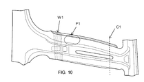
熱間プレス成形後の成形品を対象にフランジ部における硬度と形状精度を評価した。形状精度については、成形品におけるねじれとフランジ部における面外変形について評価を行った。本実施例の成形品における形状精度の評価位置を図10に示す。形状精度の基準は、(a)のデータを基準として、条件(b)(c)(d)について評価した。
The hardness and shape accuracy of the flange were evaluated for the molded product after hot press molding. Regarding the shape accuracy, the twist in the molded product and the out-of-plane deformation in the flange were evaluated. The evaluation position of the shape accuracy in the molded product of this example is shown in FIG. The shape accuracy criteria were evaluated for the conditions (b), (c), and (d) with reference to the data in (a).
図11は、成形品の硬度分布の結果を示すグラフである。(a)の条件の成形品と比較して、(b)と(c)の条件の成形品では、クリアランス部における硬度は低い。クリアランス部は、金型のクリアランスに対応する成形品の部分である。図11に示す結果から、固定クリアランス金型ならびにクリアランス制御金型のクリアランス部による部分軟化の効果がわかった。
FIG. 11 is a graph showing the result of the hardness distribution of the molded product. Compared with the molded product under the condition (a), the molded products under the conditions (b) and (c) have lower hardness at the clearance portion. The clearance portion is a part of a molded product corresponding to the clearance of the mold. From the results shown in FIG. 11, the effect of partial softening by the clearance portion of the fixed clearance mold and the clearance control mold was found.
図12は、成形品のねじれ角度の結果を示すグラフである。図12のグラフのねじれ角度は、図10に示すねじれ位置合わせ面W1で、(a)~(d)の成形品の位置を合わせた場合に、ねじれ評価断面C1が(a)の成形品に対してどの程度ねじれているかを示す値である。
FIG. 12 is a graph showing the result of the twist angle of the molded product. The twist angle of the graph of FIG. 12 is the twist evaluation cross section C1 of the molded product of (a) when the positions of the molded products (a) to (d) are aligned on the twist alignment surface W1 shown in FIG. It is a value indicating how much the twist is.
図12に示す結果では、(b)の固定クリアランス金型で成形した成形品では、(a)のクリアランスがない場合の条件よりねじれが大きくなる形状精度が悪化していることがわかる。一方、(c)及び(d)のクリアランス制御金型を用いてプレス成形した成形品では、ねじれ角度が(b)の半分以下となり,形状精度の改善が確認された。
From the results shown in FIG. 12, it can be seen that in the molded product molded with the fixed clearance mold of (b), the shape accuracy in which the twist becomes larger than the condition without the clearance of (a) is deteriorated. On the other hand, in the molded product press-molded using the clearance control dies of (c) and (d), the twist angle was less than half that of (b), and improvement in shape accuracy was confirmed.
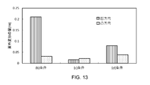
図13は、成形品の面外変形の結果を示すグラフである。図13のグラフに示す面外変形の量は、図10に示す面外変形評価位置F1における面の(a)の成形品に対する変形量を示す。面外変形評価位置F1は、(b)~(d)において、フランジ部の金型のクリアランスに対応する部分を含む位置である。図13に示す例では、クリアランス部に対応するフランジ部における局所的な形状精度も、(c)(d)のクリアランス制御金型により改善していることがわかった。
FIG. 13 is a graph showing the result of out-of-plane deformation of the molded product. The amount of out-of-plane deformation shown in the graph of FIG. 13 indicates the amount of deformation of the surface (a) at the out-of-plane deformation evaluation position F1 shown in FIG. 10 with respect to the molded product. The out-of-plane deformation evaluation position F1 is a position in (b) to (d) including a portion corresponding to the clearance of the mold of the flange portion. In the example shown in FIG. 13, it was found that the local shape accuracy of the flange portion corresponding to the clearance portion was also improved by the clearance control molds (c) and (d).
以上、本発明の一実施形態を説明したが、上述した実施形態は本発明を実施するための例示に過ぎない。よって、本発明は上述した実施形態に限定されることなく、その趣旨を逸脱しない範囲内で上述した実施形態を適宜変形して実施することが可能である。
Although one embodiment of the present invention has been described above, the above-described embodiment is merely an example for carrying out the present invention. Therefore, the present invention is not limited to the above-described embodiment, and the above-described embodiment can be appropriately modified and implemented within a range that does not deviate from the gist thereof.