WO2021200817A1 - Composition polymérisable par voie radicalaire cristalline pour fixer un aimant d'un noyau de rotor de machine dynamo-électrique, noyau de rotor de machine dynamo-électrique utilisant ladite composition, et procédé de fabrication dudit noyau de rotor de machine dynamo-électrique - Google Patents
Composition polymérisable par voie radicalaire cristalline pour fixer un aimant d'un noyau de rotor de machine dynamo-électrique, noyau de rotor de machine dynamo-électrique utilisant ladite composition, et procédé de fabrication dudit noyau de rotor de machine dynamo-électrique Download PDFInfo
- Publication number
- WO2021200817A1 WO2021200817A1 PCT/JP2021/013270 JP2021013270W WO2021200817A1 WO 2021200817 A1 WO2021200817 A1 WO 2021200817A1 JP 2021013270 W JP2021013270 W JP 2021013270W WO 2021200817 A1 WO2021200817 A1 WO 2021200817A1
- Authority
- WO
- WIPO (PCT)
- Prior art keywords
- rotor core
- polymerizable composition
- crystalline
- magnet
- rotary electric
- Prior art date
Links
- 239000000203 mixture Substances 0.000 title claims abstract description 160
- 238000004519 manufacturing process Methods 0.000 title claims description 32
- 238000000034 method Methods 0.000 title claims description 29
- 238000002347 injection Methods 0.000 claims abstract description 34
- 239000007924 injection Substances 0.000 claims abstract description 34
- 238000010438 heat treatment Methods 0.000 claims abstract description 33
- 239000011256 inorganic filler Substances 0.000 claims abstract description 29
- 229910003475 inorganic filler Inorganic materials 0.000 claims abstract description 29
- 239000000155 melt Substances 0.000 claims abstract description 27
- 229940126062 Compound A Drugs 0.000 claims abstract description 23
- NLDMNSXOCDLTTB-UHFFFAOYSA-N Heterophylliin A Natural products O1C2COC(=O)C3=CC(O)=C(O)C(O)=C3C3=C(O)C(O)=C(O)C=C3C(=O)OC2C(OC(=O)C=2C=C(O)C(O)=C(O)C=2)C(O)C1OC(=O)C1=CC(O)=C(O)C(O)=C1 NLDMNSXOCDLTTB-UHFFFAOYSA-N 0.000 claims abstract description 23
- 239000007787 solid Substances 0.000 claims abstract description 18
- 239000006087 Silane Coupling Agent Substances 0.000 claims abstract description 10
- 239000007870 radical polymerization initiator Substances 0.000 claims abstract description 6
- VYPSYNLAJGMNEJ-UHFFFAOYSA-N Silicium dioxide Chemical compound O=[Si]=O VYPSYNLAJGMNEJ-UHFFFAOYSA-N 0.000 claims description 21
- 229910000576 Laminated steel Inorganic materials 0.000 claims description 10
- 239000000377 silicon dioxide Substances 0.000 claims description 10
- 238000000465 moulding Methods 0.000 claims description 9
- 238000001746 injection moulding Methods 0.000 claims description 8
- 239000000314 lubricant Substances 0.000 claims description 8
- 238000001721 transfer moulding Methods 0.000 claims description 8
- 239000000463 material Substances 0.000 abstract description 23
- 229910000831 Steel Inorganic materials 0.000 abstract description 8
- 239000010959 steel Substances 0.000 abstract description 8
- 239000012530 fluid Substances 0.000 abstract 1
- 150000003254 radicals Chemical class 0.000 description 92
- 229920005989 resin Polymers 0.000 description 51
- 239000011347 resin Substances 0.000 description 51
- NIXOWILDQLNWCW-UHFFFAOYSA-M Acrylate Chemical compound [O-]C(=O)C=C NIXOWILDQLNWCW-UHFFFAOYSA-M 0.000 description 45
- 150000001875 compounds Chemical class 0.000 description 44
- 238000002844 melting Methods 0.000 description 32
- 230000008018 melting Effects 0.000 description 32
- 238000003825 pressing Methods 0.000 description 24
- CERQOIWHTDAKMF-UHFFFAOYSA-M Methacrylate Chemical compound CC(=C)C([O-])=O CERQOIWHTDAKMF-UHFFFAOYSA-M 0.000 description 19
- -1 hydride bisphenol Chemical compound 0.000 description 18
- 239000004721 Polyphenylene oxide Substances 0.000 description 17
- 229920000570 polyether Polymers 0.000 description 17
- LYCAIKOWRPUZTN-UHFFFAOYSA-N Ethylene glycol Chemical compound OCCO LYCAIKOWRPUZTN-UHFFFAOYSA-N 0.000 description 16
- 239000003822 epoxy resin Substances 0.000 description 15
- 229920000647 polyepoxide Polymers 0.000 description 15
- 229920000728 polyester Polymers 0.000 description 15
- 239000004593 Epoxy Substances 0.000 description 13
- IISBACLAFKSPIT-UHFFFAOYSA-N Bisphenol A Natural products C=1C=C(O)C=CC=1C(C)(C)C1=CC=C(O)C=C1 IISBACLAFKSPIT-UHFFFAOYSA-N 0.000 description 10
- 125000002887 hydroxy group Chemical group [H]O* 0.000 description 10
- DNIAPMSPPWPWGF-UHFFFAOYSA-N Propylene glycol Chemical compound CC(O)CO DNIAPMSPPWPWGF-UHFFFAOYSA-N 0.000 description 9
- MTHSVFCYNBDYFN-UHFFFAOYSA-N diethylene glycol Chemical compound OCCOCCO MTHSVFCYNBDYFN-UHFFFAOYSA-N 0.000 description 9
- 150000007519 polyprotic acids Polymers 0.000 description 9
- NIXOWILDQLNWCW-UHFFFAOYSA-N 2-Propenoic acid Natural products OC(=O)C=C NIXOWILDQLNWCW-UHFFFAOYSA-N 0.000 description 8
- XFCMNSHQOZQILR-UHFFFAOYSA-N 2-[2-(2-methylprop-2-enoyloxy)ethoxy]ethyl 2-methylprop-2-enoate Chemical compound CC(=C)C(=O)OCCOCCOC(=O)C(C)=C XFCMNSHQOZQILR-UHFFFAOYSA-N 0.000 description 8
- 238000006243 chemical reaction Methods 0.000 description 8
- 230000000052 comparative effect Effects 0.000 description 8
- 238000011049 filling Methods 0.000 description 8
- 239000011521 glass Substances 0.000 description 8
- JOYRKODLDBILNP-UHFFFAOYSA-N Ethyl urethane Chemical compound CCOC(N)=O JOYRKODLDBILNP-UHFFFAOYSA-N 0.000 description 7
- BGPVFRJUHWVFKM-UHFFFAOYSA-N N1=C2C=CC=CC2=[N+]([O-])C1(CC1)CCC21N=C1C=CC=CC1=[N+]2[O-] Chemical compound N1=C2C=CC=CC2=[N+]([O-])C1(CC1)CCC21N=C1C=CC=CC1=[N+]2[O-] BGPVFRJUHWVFKM-UHFFFAOYSA-N 0.000 description 7
- PPBRXRYQALVLMV-UHFFFAOYSA-N Styrene Chemical compound C=CC1=CC=CC=C1 PPBRXRYQALVLMV-UHFFFAOYSA-N 0.000 description 7
- 239000002253 acid Substances 0.000 description 7
- 238000005259 measurement Methods 0.000 description 7
- 239000002245 particle Substances 0.000 description 7
- 229920005906 polyester polyol Polymers 0.000 description 7
- 229920005862 polyol Polymers 0.000 description 7
- 150000003077 polyols Chemical class 0.000 description 7
- 229920006305 unsaturated polyester Polymers 0.000 description 7
- YPFDHNVEDLHUCE-UHFFFAOYSA-N 1,3-propanediol Substances OCCCO YPFDHNVEDLHUCE-UHFFFAOYSA-N 0.000 description 6
- SMZOUWXMTYCWNB-UHFFFAOYSA-N 2-(2-methoxy-5-methylphenyl)ethanamine Chemical compound COC1=CC=C(C)C=C1CCN SMZOUWXMTYCWNB-UHFFFAOYSA-N 0.000 description 6
- CERQOIWHTDAKMF-UHFFFAOYSA-N Methacrylic acid Chemical compound CC(=C)C(O)=O CERQOIWHTDAKMF-UHFFFAOYSA-N 0.000 description 6
- KKEYFWRCBNTPAC-UHFFFAOYSA-N Terephthalic acid Chemical compound OC(=O)C1=CC=C(C(O)=O)C=C1 KKEYFWRCBNTPAC-UHFFFAOYSA-N 0.000 description 6
- WYURNTSHIVDZCO-UHFFFAOYSA-N Tetrahydrofuran Chemical compound C1CCOC1 WYURNTSHIVDZCO-UHFFFAOYSA-N 0.000 description 6
- 230000005611 electricity Effects 0.000 description 6
- 239000012948 isocyanate Substances 0.000 description 6
- QQVIHTHCMHWDBS-UHFFFAOYSA-N isophthalic acid Chemical compound OC(=O)C1=CC=CC(C(O)=O)=C1 QQVIHTHCMHWDBS-UHFFFAOYSA-N 0.000 description 6
- 238000002156 mixing Methods 0.000 description 6
- 230000008569 process Effects 0.000 description 6
- 239000007822 coupling agent Substances 0.000 description 5
- 239000003365 glass fiber Substances 0.000 description 5
- LNEPOXFFQSENCJ-UHFFFAOYSA-N haloperidol Chemical compound C1CC(O)(C=2C=CC(Cl)=CC=2)CCN1CCCC(=O)C1=CC=C(F)C=C1 LNEPOXFFQSENCJ-UHFFFAOYSA-N 0.000 description 5
- 239000003112 inhibitor Substances 0.000 description 5
- 150000002513 isocyanates Chemical class 0.000 description 5
- 238000006116 polymerization reaction Methods 0.000 description 5
- 239000012779 reinforcing material Substances 0.000 description 5
- 229920006395 saturated elastomer Polymers 0.000 description 5
- 150000005846 sugar alcohols Polymers 0.000 description 5
- 229920001187 thermosetting polymer Polymers 0.000 description 5
- PUPZLCDOIYMWBV-UHFFFAOYSA-N (+/-)-1,3-Butanediol Chemical compound CC(O)CCO PUPZLCDOIYMWBV-UHFFFAOYSA-N 0.000 description 4
- AZQWKYJCGOJGHM-UHFFFAOYSA-N 1,4-benzoquinone Chemical compound O=C1C=CC(=O)C=C1 AZQWKYJCGOJGHM-UHFFFAOYSA-N 0.000 description 4
- 239000004925 Acrylic resin Substances 0.000 description 4
- VZCYOOQTPOCHFL-OWOJBTEDSA-N Fumaric acid Chemical compound OC(=O)\C=C\C(O)=O VZCYOOQTPOCHFL-OWOJBTEDSA-N 0.000 description 4
- UFWIBTONFRDIAS-UHFFFAOYSA-N Naphthalene Chemical compound C1=CC=CC2=CC=CC=C21 UFWIBTONFRDIAS-UHFFFAOYSA-N 0.000 description 4
- 239000000654 additive Substances 0.000 description 4
- WNLRTRBMVRJNCN-UHFFFAOYSA-N adipic acid Chemical compound OC(=O)CCCCC(O)=O WNLRTRBMVRJNCN-UHFFFAOYSA-N 0.000 description 4
- 230000001476 alcoholic effect Effects 0.000 description 4
- WERYXYBDKMZEQL-UHFFFAOYSA-N butane-1,4-diol Chemical compound OCCCCO WERYXYBDKMZEQL-UHFFFAOYSA-N 0.000 description 4
- 239000003795 chemical substances by application Substances 0.000 description 4
- SZXQTJUDPRGNJN-UHFFFAOYSA-N dipropylene glycol Chemical compound OCCCOCCCO SZXQTJUDPRGNJN-UHFFFAOYSA-N 0.000 description 4
- 230000000694 effects Effects 0.000 description 4
- 125000003055 glycidyl group Chemical group C(C1CO1)* 0.000 description 4
- 230000001771 impaired effect Effects 0.000 description 4
- 238000003780 insertion Methods 0.000 description 4
- 230000037431 insertion Effects 0.000 description 4
- IQPQWNKOIGAROB-UHFFFAOYSA-N isocyanate group Chemical group [N-]=C=O IQPQWNKOIGAROB-UHFFFAOYSA-N 0.000 description 4
- SLCVBVWXLSEKPL-UHFFFAOYSA-N neopentyl glycol Chemical compound OCC(C)(C)CO SLCVBVWXLSEKPL-UHFFFAOYSA-N 0.000 description 4
- XNGIFLGASWRNHJ-UHFFFAOYSA-N phthalic acid Chemical compound OC(=O)C1=CC=CC=C1C(O)=O XNGIFLGASWRNHJ-UHFFFAOYSA-N 0.000 description 4
- 238000003860 storage Methods 0.000 description 4
- XMNIXWIUMCBBBL-UHFFFAOYSA-N 2-(2-phenylpropan-2-ylperoxy)propan-2-ylbenzene Chemical compound C=1C=CC=CC=1C(C)(C)OOC(C)(C)C1=CC=CC=C1 XMNIXWIUMCBBBL-UHFFFAOYSA-N 0.000 description 3
- ALQSHHUCVQOPAS-UHFFFAOYSA-N Pentane-1,5-diol Chemical compound OCCCCCO ALQSHHUCVQOPAS-UHFFFAOYSA-N 0.000 description 3
- 239000000470 constituent Substances 0.000 description 3
- 238000007796 conventional method Methods 0.000 description 3
- GYZLOYUZLJXAJU-UHFFFAOYSA-N diglycidyl ether Chemical group C1OC1COCC1CO1 GYZLOYUZLJXAJU-UHFFFAOYSA-N 0.000 description 3
- 238000011156 evaluation Methods 0.000 description 3
- 239000000835 fiber Substances 0.000 description 3
- 230000009477 glass transition Effects 0.000 description 3
- 150000002334 glycols Chemical class 0.000 description 3
- XXMIOPMDWAUFGU-UHFFFAOYSA-N hexane-1,6-diol Chemical compound OCCCCCCO XXMIOPMDWAUFGU-UHFFFAOYSA-N 0.000 description 3
- 239000007788 liquid Substances 0.000 description 3
- 229910052751 metal Inorganic materials 0.000 description 3
- 239000002184 metal Substances 0.000 description 3
- OEIJHBUUFURJLI-UHFFFAOYSA-N octane-1,8-diol Chemical compound OCCCCCCCCO OEIJHBUUFURJLI-UHFFFAOYSA-N 0.000 description 3
- 150000001451 organic peroxides Chemical class 0.000 description 3
- KCTAWXVAICEBSD-UHFFFAOYSA-N prop-2-enoyloxy prop-2-eneperoxoate Chemical compound C=CC(=O)OOOC(=O)C=C KCTAWXVAICEBSD-UHFFFAOYSA-N 0.000 description 3
- 239000011342 resin composition Substances 0.000 description 3
- YLQBMQCUIZJEEH-UHFFFAOYSA-N tetrahydrofuran Natural products C=1C=COC=1 YLQBMQCUIZJEEH-UHFFFAOYSA-N 0.000 description 3
- VZCYOOQTPOCHFL-UHFFFAOYSA-N trans-butenedioic acid Natural products OC(=O)C=CC(O)=O VZCYOOQTPOCHFL-UHFFFAOYSA-N 0.000 description 3
- DNIAPMSPPWPWGF-VKHMYHEASA-N (+)-propylene glycol Chemical compound C[C@H](O)CO DNIAPMSPPWPWGF-VKHMYHEASA-N 0.000 description 2
- FKTHNVSLHLHISI-UHFFFAOYSA-N 1,2-bis(isocyanatomethyl)benzene Chemical compound O=C=NCC1=CC=CC=C1CN=C=O FKTHNVSLHLHISI-UHFFFAOYSA-N 0.000 description 2
- VNGLVZLEUDIDQH-UHFFFAOYSA-N 4-[2-(4-hydroxyphenyl)propan-2-yl]phenol;2-methyloxirane Chemical compound CC1CO1.C=1C=C(O)C=CC=1C(C)(C)C1=CC=C(O)C=C1 VNGLVZLEUDIDQH-UHFFFAOYSA-N 0.000 description 2
- WPSWDCBWMRJJED-UHFFFAOYSA-N 4-[2-(4-hydroxyphenyl)propan-2-yl]phenol;oxirane Chemical compound C1CO1.C=1C=C(O)C=CC=1C(C)(C)C1=CC=C(O)C=C1 WPSWDCBWMRJJED-UHFFFAOYSA-N 0.000 description 2
- RSWGJHLUYNHPMX-UHFFFAOYSA-N Abietic-Saeure Natural products C12CCC(C(C)C)=CC2=CCC2C1(C)CCCC2(C)C(O)=O RSWGJHLUYNHPMX-UHFFFAOYSA-N 0.000 description 2
- 239000004412 Bulk moulding compound Substances 0.000 description 2
- SOGAXMICEFXMKE-UHFFFAOYSA-N Butylmethacrylate Chemical compound CCCCOC(=O)C(C)=C SOGAXMICEFXMKE-UHFFFAOYSA-N 0.000 description 2
- VTYYLEPIZMXCLO-UHFFFAOYSA-L Calcium carbonate Chemical compound [Ca+2].[O-]C([O-])=O VTYYLEPIZMXCLO-UHFFFAOYSA-L 0.000 description 2
- 239000004641 Diallyl-phthalate Substances 0.000 description 2
- UFHFLCQGNIYNRP-UHFFFAOYSA-N Hydrogen Chemical compound [H][H] UFHFLCQGNIYNRP-UHFFFAOYSA-N 0.000 description 2
- QIGBRXMKCJKVMJ-UHFFFAOYSA-N Hydroquinone Chemical compound OC1=CC=C(O)C=C1 QIGBRXMKCJKVMJ-UHFFFAOYSA-N 0.000 description 2
- BAPJBEWLBFYGME-UHFFFAOYSA-N Methyl acrylate Chemical compound COC(=O)C=C BAPJBEWLBFYGME-UHFFFAOYSA-N 0.000 description 2
- QCXXDZUWBAHYPA-UHFFFAOYSA-N OC(=O)C=C.OC(=O)C=C.OC(=O)C=C.O=C1NC(=O)NC(=O)N1 Chemical class OC(=O)C=C.OC(=O)C=C.OC(=O)C=C.O=C1NC(=O)NC(=O)N1 QCXXDZUWBAHYPA-UHFFFAOYSA-N 0.000 description 2
- NBIIXXVUZAFLBC-UHFFFAOYSA-N Phosphoric acid Chemical compound OP(O)(O)=O NBIIXXVUZAFLBC-UHFFFAOYSA-N 0.000 description 2
- LGRFSURHDFAFJT-UHFFFAOYSA-N Phthalic anhydride Natural products C1=CC=C2C(=O)OC(=O)C2=C1 LGRFSURHDFAFJT-UHFFFAOYSA-N 0.000 description 2
- 239000002202 Polyethylene glycol Substances 0.000 description 2
- 239000003677 Sheet moulding compound Substances 0.000 description 2
- BLRPTPMANUNPDV-UHFFFAOYSA-N Silane Chemical compound [SiH4] BLRPTPMANUNPDV-UHFFFAOYSA-N 0.000 description 2
- XLOMVQKBTHCTTD-UHFFFAOYSA-N Zinc monoxide Chemical compound [Zn]=O XLOMVQKBTHCTTD-UHFFFAOYSA-N 0.000 description 2
- ORLQHILJRHBSAY-UHFFFAOYSA-N [1-(hydroxymethyl)cyclohexyl]methanol Chemical compound OCC1(CO)CCCCC1 ORLQHILJRHBSAY-UHFFFAOYSA-N 0.000 description 2
- 239000001361 adipic acid Substances 0.000 description 2
- 235000011037 adipic acid Nutrition 0.000 description 2
- 239000003513 alkali Substances 0.000 description 2
- KGQLBLGDIQNGSB-UHFFFAOYSA-N benzene-1,4-diol;methoxymethane Chemical compound COC.OC1=CC=C(O)C=C1 KGQLBLGDIQNGSB-UHFFFAOYSA-N 0.000 description 2
- 230000001588 bifunctional effect Effects 0.000 description 2
- QUDWYFHPNIMBFC-UHFFFAOYSA-N bis(prop-2-enyl) benzene-1,2-dicarboxylate Chemical compound C=CCOC(=O)C1=CC=CC=C1C(=O)OCC=C QUDWYFHPNIMBFC-UHFFFAOYSA-N 0.000 description 2
- PXKLMJQFEQBVLD-UHFFFAOYSA-N bisphenol F Chemical compound C1=CC(O)=CC=C1CC1=CC=C(O)C=C1 PXKLMJQFEQBVLD-UHFFFAOYSA-N 0.000 description 2
- JHIWVOJDXOSYLW-UHFFFAOYSA-N butyl 2,2-difluorocyclopropane-1-carboxylate Chemical compound CCCCOC(=O)C1CC1(F)F JHIWVOJDXOSYLW-UHFFFAOYSA-N 0.000 description 2
- 238000005266 casting Methods 0.000 description 2
- 239000003054 catalyst Substances 0.000 description 2
- 230000008859 change Effects 0.000 description 2
- 239000003086 colorant Substances 0.000 description 2
- 238000013329 compounding Methods 0.000 description 2
- 238000006482 condensation reaction Methods 0.000 description 2
- 238000010924 continuous production Methods 0.000 description 2
- 238000001816 cooling Methods 0.000 description 2
- 230000007423 decrease Effects 0.000 description 2
- 230000018044 dehydration Effects 0.000 description 2
- 238000006297 dehydration reaction Methods 0.000 description 2
- 235000014113 dietary fatty acids Nutrition 0.000 description 2
- 125000005442 diisocyanate group Chemical group 0.000 description 2
- 230000032050 esterification Effects 0.000 description 2
- 238000005886 esterification reaction Methods 0.000 description 2
- MHCLJIVVJQQNKQ-UHFFFAOYSA-N ethyl carbamate;2-methylprop-2-enoic acid Chemical compound CCOC(N)=O.CC(=C)C(O)=O MHCLJIVVJQQNKQ-UHFFFAOYSA-N 0.000 description 2
- UHESRSKEBRADOO-UHFFFAOYSA-N ethyl carbamate;prop-2-enoic acid Chemical compound OC(=O)C=C.CCOC(N)=O UHESRSKEBRADOO-UHFFFAOYSA-N 0.000 description 2
- 239000000194 fatty acid Substances 0.000 description 2
- 229930195729 fatty acid Natural products 0.000 description 2
- 230000004907 flux Effects 0.000 description 2
- 239000001530 fumaric acid Substances 0.000 description 2
- 238000005227 gel permeation chromatography Methods 0.000 description 2
- 239000008187 granular material Substances 0.000 description 2
- 230000017525 heat dissipation Effects 0.000 description 2
- PYGSKMBEVAICCR-UHFFFAOYSA-N hexa-1,5-diene Chemical group C=CCCC=C PYGSKMBEVAICCR-UHFFFAOYSA-N 0.000 description 2
- 239000001257 hydrogen Substances 0.000 description 2
- 229910052739 hydrogen Inorganic materials 0.000 description 2
- WGCNASOHLSPBMP-UHFFFAOYSA-N hydroxyacetaldehyde Natural products OCC=O WGCNASOHLSPBMP-UHFFFAOYSA-N 0.000 description 2
- 230000006698 induction Effects 0.000 description 2
- 239000004615 ingredient Substances 0.000 description 2
- ZFSLODLOARCGLH-UHFFFAOYSA-N isocyanuric acid Chemical group OC1=NC(O)=NC(O)=N1 ZFSLODLOARCGLH-UHFFFAOYSA-N 0.000 description 2
- 239000000395 magnesium oxide Substances 0.000 description 2
- CPLXHLVBOLITMK-UHFFFAOYSA-N magnesium oxide Inorganic materials [Mg]=O CPLXHLVBOLITMK-UHFFFAOYSA-N 0.000 description 2
- AXZKOIWUVFPNLO-UHFFFAOYSA-N magnesium;oxygen(2-) Chemical compound [O-2].[Mg+2] AXZKOIWUVFPNLO-UHFFFAOYSA-N 0.000 description 2
- 230000005415 magnetization Effects 0.000 description 2
- 239000012778 molding material Substances 0.000 description 2
- BDJRBEYXGGNYIS-UHFFFAOYSA-N nonanedioic acid Chemical compound OC(=O)CCCCCCCC(O)=O BDJRBEYXGGNYIS-UHFFFAOYSA-N 0.000 description 2
- 230000000704 physical effect Effects 0.000 description 2
- 229920001223 polyethylene glycol Polymers 0.000 description 2
- 229920000166 polytrimethylene carbonate Polymers 0.000 description 2
- 238000011417 postcuring Methods 0.000 description 2
- WQGWDDDVZFFDIG-UHFFFAOYSA-N pyrogallol Chemical compound OC1=CC=CC(O)=C1O WQGWDDDVZFFDIG-UHFFFAOYSA-N 0.000 description 2
- 238000007142 ring opening reaction Methods 0.000 description 2
- 238000007789 sealing Methods 0.000 description 2
- 229910000077 silane Inorganic materials 0.000 description 2
- 239000005368 silicate glass Substances 0.000 description 2
- 229910001220 stainless steel Inorganic materials 0.000 description 2
- 239000010935 stainless steel Substances 0.000 description 2
- 239000000126 substance Substances 0.000 description 2
- 125000001424 substituent group Chemical group 0.000 description 2
- 239000000758 substrate Substances 0.000 description 2
- 230000008719 thickening Effects 0.000 description 2
- 239000002562 thickening agent Substances 0.000 description 2
- 238000012546 transfer Methods 0.000 description 2
- 230000007704 transition Effects 0.000 description 2
- ARCGXLSVLAOJQL-UHFFFAOYSA-N trimellitic acid Chemical compound OC(=O)C1=CC=C(C(O)=O)C(C(O)=O)=C1 ARCGXLSVLAOJQL-UHFFFAOYSA-N 0.000 description 2
- 125000000391 vinyl group Chemical group [H]C([*])=C([H])[H] 0.000 description 2
- 239000001993 wax Substances 0.000 description 2
- XOOUIPVCVHRTMJ-UHFFFAOYSA-L zinc stearate Chemical compound [Zn+2].CCCCCCCCCCCCCCCCCC([O-])=O.CCCCCCCCCCCCCCCCCC([O-])=O XOOUIPVCVHRTMJ-UHFFFAOYSA-L 0.000 description 2
- JXCAHDJDIAQCJO-UHFFFAOYSA-N (1-tert-butylperoxy-2-ethylhexyl) hydrogen carbonate Chemical compound CCCCC(CC)C(OC(O)=O)OOC(C)(C)C JXCAHDJDIAQCJO-UHFFFAOYSA-N 0.000 description 1
- QEQBMZQFDDDTPN-UHFFFAOYSA-N (2-methylpropan-2-yl)oxy benzenecarboperoxoate Chemical compound CC(C)(C)OOOC(=O)C1=CC=CC=C1 QEQBMZQFDDDTPN-UHFFFAOYSA-N 0.000 description 1
- KMOUUZVZFBCRAM-OLQVQODUSA-N (3as,7ar)-3a,4,7,7a-tetrahydro-2-benzofuran-1,3-dione Chemical compound C1C=CC[C@@H]2C(=O)OC(=O)[C@@H]21 KMOUUZVZFBCRAM-OLQVQODUSA-N 0.000 description 1
- XVOUMQNXTGKGMA-OWOJBTEDSA-N (E)-glutaconic acid Chemical compound OC(=O)C\C=C\C(O)=O XVOUMQNXTGKGMA-OWOJBTEDSA-N 0.000 description 1
- VBQCFYPTKHCPGI-UHFFFAOYSA-N 1,1-bis(2-methylpentan-2-ylperoxy)cyclohexane Chemical compound CCCC(C)(C)OOC1(OOC(C)(C)CCC)CCCCC1 VBQCFYPTKHCPGI-UHFFFAOYSA-N 0.000 description 1
- JYEUMXHLPRZUAT-UHFFFAOYSA-N 1,2,3-triazine Chemical compound C1=CN=NN=C1 JYEUMXHLPRZUAT-UHFFFAOYSA-N 0.000 description 1
- KOMNUTZXSVSERR-UHFFFAOYSA-N 1,3,5-tris(prop-2-enyl)-1,3,5-triazinane-2,4,6-trione Chemical compound C=CCN1C(=O)N(CC=C)C(=O)N(CC=C)C1=O KOMNUTZXSVSERR-UHFFFAOYSA-N 0.000 description 1
- 229940008841 1,6-hexamethylene diisocyanate Drugs 0.000 description 1
- ALVZNPYWJMLXKV-UHFFFAOYSA-N 1,9-Nonanediol Chemical compound OCCCCCCCCCO ALVZNPYWJMLXKV-UHFFFAOYSA-N 0.000 description 1
- XHAFIUUYXQFJEW-UHFFFAOYSA-N 1-chloroethenylbenzene Chemical compound ClC(=C)C1=CC=CC=C1 XHAFIUUYXQFJEW-UHFFFAOYSA-N 0.000 description 1
- WJFKNYWRSNBZNX-UHFFFAOYSA-N 10H-phenothiazine Chemical compound C1=CC=C2NC3=CC=CC=C3SC2=C1 WJFKNYWRSNBZNX-UHFFFAOYSA-N 0.000 description 1
- KGRVJHAUYBGFFP-UHFFFAOYSA-N 2,2'-Methylenebis(4-methyl-6-tert-butylphenol) Chemical compound CC(C)(C)C1=CC(C)=CC(CC=2C(=C(C=C(C)C=2)C(C)(C)C)O)=C1O KGRVJHAUYBGFFP-UHFFFAOYSA-N 0.000 description 1
- BJELTSYBAHKXRW-UHFFFAOYSA-N 2,4,6-triallyloxy-1,3,5-triazine Chemical compound C=CCOC1=NC(OCC=C)=NC(OCC=C)=N1 BJELTSYBAHKXRW-UHFFFAOYSA-N 0.000 description 1
- JAHNSTQSQJOJLO-UHFFFAOYSA-N 2-(3-fluorophenyl)-1h-imidazole Chemical compound FC1=CC=CC(C=2NC=CN=2)=C1 JAHNSTQSQJOJLO-UHFFFAOYSA-N 0.000 description 1
- WFUGQJXVXHBTEM-UHFFFAOYSA-N 2-hydroperoxy-2-(2-hydroperoxybutan-2-ylperoxy)butane Chemical compound CCC(C)(OO)OOC(C)(CC)OO WFUGQJXVXHBTEM-UHFFFAOYSA-N 0.000 description 1
- OMIGHNLMNHATMP-UHFFFAOYSA-N 2-hydroxyethyl prop-2-enoate Chemical compound OCCOC(=O)C=C OMIGHNLMNHATMP-UHFFFAOYSA-N 0.000 description 1
- RZVINYQDSSQUKO-UHFFFAOYSA-N 2-phenoxyethyl prop-2-enoate Chemical compound C=CC(=O)OCCOC1=CC=CC=C1 RZVINYQDSSQUKO-UHFFFAOYSA-N 0.000 description 1
- 125000003903 2-propenyl group Chemical group [H]C([*])([H])C([H])=C([H])[H] 0.000 description 1
- JIGUICYYOYEXFS-UHFFFAOYSA-N 3-tert-butylbenzene-1,2-diol Chemical compound CC(C)(C)C1=CC=CC(O)=C1O JIGUICYYOYEXFS-UHFFFAOYSA-N 0.000 description 1
- XDLMVUHYZWKMMD-UHFFFAOYSA-N 3-trimethoxysilylpropyl 2-methylprop-2-enoate Chemical compound CO[Si](OC)(OC)CCCOC(=O)C(C)=C XDLMVUHYZWKMMD-UHFFFAOYSA-N 0.000 description 1
- UPMLOUAZCHDJJD-UHFFFAOYSA-N 4,4'-Diphenylmethane Diisocyanate Chemical compound C1=CC(N=C=O)=CC=C1CC1=CC=C(N=C=O)C=C1 UPMLOUAZCHDJJD-UHFFFAOYSA-N 0.000 description 1
- VPWNQTHUCYMVMZ-UHFFFAOYSA-N 4,4'-sulfonyldiphenol Chemical compound C1=CC(O)=CC=C1S(=O)(=O)C1=CC=C(O)C=C1 VPWNQTHUCYMVMZ-UHFFFAOYSA-N 0.000 description 1
- UZFMOKQJFYMBGY-UHFFFAOYSA-N 4-hydroxy-TEMPO Chemical group CC1(C)CC(O)CC(C)(C)N1[O] UZFMOKQJFYMBGY-UHFFFAOYSA-N 0.000 description 1
- SFXHWRCRQNGVLJ-UHFFFAOYSA-N 4-methoxy-TEMPO Chemical group COC1CC(C)(C)N([O])C(C)(C)C1 SFXHWRCRQNGVLJ-UHFFFAOYSA-N 0.000 description 1
- WSGDRFHJFJRSFY-UHFFFAOYSA-N 4-oxo-TEMPO Chemical group CC1(C)CC(=O)CC(C)(C)N1[O] WSGDRFHJFJRSFY-UHFFFAOYSA-N 0.000 description 1
- MWSKJDNQKGCKPA-UHFFFAOYSA-N 6-methyl-3a,4,5,7a-tetrahydro-2-benzofuran-1,3-dione Chemical compound C1CC(C)=CC2C(=O)OC(=O)C12 MWSKJDNQKGCKPA-UHFFFAOYSA-N 0.000 description 1
- FIHBHSQYSYVZQE-UHFFFAOYSA-N 6-prop-2-enoyloxyhexyl prop-2-enoate Chemical compound C=CC(=O)OCCCCCCOC(=O)C=C FIHBHSQYSYVZQE-UHFFFAOYSA-N 0.000 description 1
- KNDQHSIWLOJIGP-UHFFFAOYSA-N 826-62-0 Chemical compound C1C2C3C(=O)OC(=O)C3C1C=C2 KNDQHSIWLOJIGP-UHFFFAOYSA-N 0.000 description 1
- HRPVXLWXLXDGHG-UHFFFAOYSA-N Acrylamide Chemical compound NC(=O)C=C HRPVXLWXLXDGHG-UHFFFAOYSA-N 0.000 description 1
- 229910052582 BN Inorganic materials 0.000 description 1
- 239000004342 Benzoyl peroxide Substances 0.000 description 1
- OMPJBNCRMGITSC-UHFFFAOYSA-N Benzoylperoxide Chemical compound C=1C=CC=CC=1C(=O)OOC(=O)C1=CC=CC=C1 OMPJBNCRMGITSC-UHFFFAOYSA-N 0.000 description 1
- 229930185605 Bisphenol Natural products 0.000 description 1
- PZNSFCLAULLKQX-UHFFFAOYSA-N Boron nitride Chemical compound N#B PZNSFCLAULLKQX-UHFFFAOYSA-N 0.000 description 1
- GAWIXWVDTYZWAW-UHFFFAOYSA-N C[CH]O Chemical group C[CH]O GAWIXWVDTYZWAW-UHFFFAOYSA-N 0.000 description 1
- KXDHJXZQYSOELW-UHFFFAOYSA-M Carbamate Chemical compound NC([O-])=O KXDHJXZQYSOELW-UHFFFAOYSA-M 0.000 description 1
- OKTJSMMVPCPJKN-UHFFFAOYSA-N Carbon Chemical compound [C] OKTJSMMVPCPJKN-UHFFFAOYSA-N 0.000 description 1
- 229910000976 Electrical steel Inorganic materials 0.000 description 1
- JIGUQPWFLRLWPJ-UHFFFAOYSA-N Ethyl acrylate Chemical compound CCOC(=O)C=C JIGUQPWFLRLWPJ-UHFFFAOYSA-N 0.000 description 1
- IAYPIBMASNFSPL-UHFFFAOYSA-N Ethylene oxide Chemical compound C1CO1 IAYPIBMASNFSPL-UHFFFAOYSA-N 0.000 description 1
- 229920002430 Fibre-reinforced plastic Polymers 0.000 description 1
- 241000704611 Fig cryptic virus Species 0.000 description 1
- WOBHKFSMXKNTIM-UHFFFAOYSA-N Hydroxyethyl methacrylate Chemical compound CC(=C)C(=O)OCCO WOBHKFSMXKNTIM-UHFFFAOYSA-N 0.000 description 1
- XEEYBQQBJWHFJM-UHFFFAOYSA-N Iron Chemical group [Fe] XEEYBQQBJWHFJM-UHFFFAOYSA-N 0.000 description 1
- 239000005058 Isophorone diisocyanate Substances 0.000 description 1
- PEEHTFAAVSWFBL-UHFFFAOYSA-N Maleimide Chemical compound O=C1NC(=O)C=C1 PEEHTFAAVSWFBL-UHFFFAOYSA-N 0.000 description 1
- VVQNEPGJFQJSBK-UHFFFAOYSA-N Methyl methacrylate Chemical compound COC(=O)C(C)=C VVQNEPGJFQJSBK-UHFFFAOYSA-N 0.000 description 1
- CNCOEDDPFOAUMB-UHFFFAOYSA-N N-Methylolacrylamide Chemical compound OCNC(=O)C=C CNCOEDDPFOAUMB-UHFFFAOYSA-N 0.000 description 1
- CTQNGGLPUBDAKN-UHFFFAOYSA-N O-Xylene Chemical compound CC1=CC=CC=C1C CTQNGGLPUBDAKN-UHFFFAOYSA-N 0.000 description 1
- 229910019142 PO4 Inorganic materials 0.000 description 1
- 239000004793 Polystyrene Substances 0.000 description 1
- OFOBLEOULBTSOW-UHFFFAOYSA-N Propanedioic acid Natural products OC(=O)CC(O)=O OFOBLEOULBTSOW-UHFFFAOYSA-N 0.000 description 1
- GOOHAUXETOMSMM-UHFFFAOYSA-N Propylene oxide Chemical compound CC1CO1 GOOHAUXETOMSMM-UHFFFAOYSA-N 0.000 description 1
- KHPCPRHQVVSZAH-HUOMCSJISA-N Rosin Natural products O(C/C=C/c1ccccc1)[C@H]1[C@H](O)[C@@H](O)[C@@H](O)[C@@H](CO)O1 KHPCPRHQVVSZAH-HUOMCSJISA-N 0.000 description 1
- 235000021355 Stearic acid Nutrition 0.000 description 1
- KDYFGRWQOYBRFD-UHFFFAOYSA-N Succinic acid Natural products OC(=O)CCC(O)=O KDYFGRWQOYBRFD-UHFFFAOYSA-N 0.000 description 1
- RTAQQCXQSZGOHL-UHFFFAOYSA-N Titanium Chemical compound [Ti] RTAQQCXQSZGOHL-UHFFFAOYSA-N 0.000 description 1
- XTXRWKRVRITETP-UHFFFAOYSA-N Vinyl acetate Chemical compound CC(=O)OC=C XTXRWKRVRITETP-UHFFFAOYSA-N 0.000 description 1
- 125000004054 acenaphthylenyl group Chemical group C1(=CC2=CC=CC3=CC=CC1=C23)* 0.000 description 1
- HXGDTGSAIMULJN-UHFFFAOYSA-N acetnaphthylene Natural products C1=CC(C=C2)=C3C2=CC=CC3=C1 HXGDTGSAIMULJN-UHFFFAOYSA-N 0.000 description 1
- YRKCREAYFQTBPV-UHFFFAOYSA-N acetylacetone Natural products CC(=O)CC(C)=O YRKCREAYFQTBPV-UHFFFAOYSA-N 0.000 description 1
- 150000001252 acrylic acid derivatives Chemical class 0.000 description 1
- 230000002411 adverse Effects 0.000 description 1
- 150000001298 alcohols Chemical class 0.000 description 1
- 125000001931 aliphatic group Chemical group 0.000 description 1
- 125000005370 alkoxysilyl group Chemical group 0.000 description 1
- XYLMUPLGERFSHI-UHFFFAOYSA-N alpha-Methylstyrene Chemical compound CC(=C)C1=CC=CC=C1 XYLMUPLGERFSHI-UHFFFAOYSA-N 0.000 description 1
- 229910052782 aluminium Inorganic materials 0.000 description 1
- XAGFODPZIPBFFR-UHFFFAOYSA-N aluminium Chemical compound [Al] XAGFODPZIPBFFR-UHFFFAOYSA-N 0.000 description 1
- WNROFYMDJYEPJX-UHFFFAOYSA-K aluminium hydroxide Chemical compound [OH-].[OH-].[OH-].[Al+3] WNROFYMDJYEPJX-UHFFFAOYSA-K 0.000 description 1
- PNEYBMLMFCGWSK-UHFFFAOYSA-N aluminium oxide Inorganic materials [O-2].[O-2].[O-2].[Al+3].[Al+3] PNEYBMLMFCGWSK-UHFFFAOYSA-N 0.000 description 1
- 229910000147 aluminium phosphate Inorganic materials 0.000 description 1
- CEGOLXSVJUTHNZ-UHFFFAOYSA-K aluminium tristearate Chemical compound [Al+3].CCCCCCCCCCCCCCCCCC([O-])=O.CCCCCCCCCCCCCCCCCC([O-])=O.CCCCCCCCCCCCCCCCCC([O-])=O CEGOLXSVJUTHNZ-UHFFFAOYSA-K 0.000 description 1
- 229940063655 aluminum stearate Drugs 0.000 description 1
- 125000003277 amino group Chemical group 0.000 description 1
- 125000003118 aryl group Chemical group 0.000 description 1
- 239000012298 atmosphere Substances 0.000 description 1
- QVGXLLKOCUKJST-UHFFFAOYSA-N atomic oxygen Chemical compound [O] QVGXLLKOCUKJST-UHFFFAOYSA-N 0.000 description 1
- AYJRCSIUFZENHW-DEQYMQKBSA-L barium(2+);oxomethanediolate Chemical compound [Ba+2].[O-][14C]([O-])=O AYJRCSIUFZENHW-DEQYMQKBSA-L 0.000 description 1
- QRUDEWIWKLJBPS-UHFFFAOYSA-N benzotriazole Chemical compound C1=CC=C2N[N][N]C2=C1 QRUDEWIWKLJBPS-UHFFFAOYSA-N 0.000 description 1
- 239000012964 benzotriazole Substances 0.000 description 1
- 235000019400 benzoyl peroxide Nutrition 0.000 description 1
- HIFVAOIJYDXIJG-UHFFFAOYSA-N benzylbenzene;isocyanic acid Chemical class N=C=O.N=C=O.C=1C=CC=CC=1CC1=CC=CC=C1 HIFVAOIJYDXIJG-UHFFFAOYSA-N 0.000 description 1
- 239000001273 butane Substances 0.000 description 1
- BMRWNKZVCUKKSR-UHFFFAOYSA-N butane-1,2-diol Chemical compound CCC(O)CO BMRWNKZVCUKKSR-UHFFFAOYSA-N 0.000 description 1
- KDYFGRWQOYBRFD-NUQCWPJISA-N butanedioic acid Chemical compound O[14C](=O)CC[14C](O)=O KDYFGRWQOYBRFD-NUQCWPJISA-N 0.000 description 1
- CQEYYJKEWSMYFG-UHFFFAOYSA-N butyl acrylate Chemical compound CCCCOC(=O)C=C CQEYYJKEWSMYFG-UHFFFAOYSA-N 0.000 description 1
- 229910000019 calcium carbonate Inorganic materials 0.000 description 1
- AXCZMVOFGPJBDE-UHFFFAOYSA-L calcium dihydroxide Chemical compound [OH-].[OH-].[Ca+2] AXCZMVOFGPJBDE-UHFFFAOYSA-L 0.000 description 1
- 239000000920 calcium hydroxide Substances 0.000 description 1
- 229910001861 calcium hydroxide Inorganic materials 0.000 description 1
- CJZGTCYPCWQAJB-UHFFFAOYSA-L calcium stearate Chemical compound [Ca+2].CCCCCCCCCCCCCCCCCC([O-])=O.CCCCCCCCCCCCCCCCCC([O-])=O CJZGTCYPCWQAJB-UHFFFAOYSA-L 0.000 description 1
- 239000008116 calcium stearate Substances 0.000 description 1
- 235000013539 calcium stearate Nutrition 0.000 description 1
- 229910052799 carbon Inorganic materials 0.000 description 1
- 239000006229 carbon black Substances 0.000 description 1
- 125000003178 carboxy group Chemical group [H]OC(*)=O 0.000 description 1
- HNEGQIOMVPPMNR-IHWYPQMZSA-N citraconic acid Chemical compound OC(=O)C(/C)=C\C(O)=O HNEGQIOMVPPMNR-IHWYPQMZSA-N 0.000 description 1
- 229940018557 citraconic acid Drugs 0.000 description 1
- 239000004927 clay Substances 0.000 description 1
- 239000002131 composite material Substances 0.000 description 1
- 229940125904 compound 1 Drugs 0.000 description 1
- 229940125782 compound 2 Drugs 0.000 description 1
- 229940126214 compound 3 Drugs 0.000 description 1
- PMHQVHHXPFUNSP-UHFFFAOYSA-M copper(1+);methylsulfanylmethane;bromide Chemical compound Br[Cu].CSC PMHQVHHXPFUNSP-UHFFFAOYSA-M 0.000 description 1
- 238000002425 crystallisation Methods 0.000 description 1
- 230000008025 crystallization Effects 0.000 description 1
- IFDVQVHZEKPUSC-UHFFFAOYSA-N cyclohex-3-ene-1,2-dicarboxylic acid Chemical compound OC(=O)C1CCC=CC1C(O)=O IFDVQVHZEKPUSC-UHFFFAOYSA-N 0.000 description 1
- FOTKYAAJKYLFFN-UHFFFAOYSA-N decane-1,10-diol Chemical compound OCCCCCCCCCCO FOTKYAAJKYLFFN-UHFFFAOYSA-N 0.000 description 1
- KIQKWYUGPPFMBV-UHFFFAOYSA-N diisocyanatomethane Chemical compound O=C=NCN=C=O KIQKWYUGPPFMBV-UHFFFAOYSA-N 0.000 description 1
- ZWWQRMFIZFPUAA-UHFFFAOYSA-N dimethyl 2-methylidenebutanedioate Chemical compound COC(=O)CC(=C)C(=O)OC ZWWQRMFIZFPUAA-UHFFFAOYSA-N 0.000 description 1
- 239000002270 dispersing agent Substances 0.000 description 1
- KHAYCTOSKLIHEP-UHFFFAOYSA-N docosyl prop-2-enoate Chemical compound CCCCCCCCCCCCCCCCCCCCCCOC(=O)C=C KHAYCTOSKLIHEP-UHFFFAOYSA-N 0.000 description 1
- MPOGZNTVZCEKSW-UHFFFAOYSA-N ethenyl 2-hydroxypropanoate Chemical compound CC(O)C(=O)OC=C MPOGZNTVZCEKSW-UHFFFAOYSA-N 0.000 description 1
- MEGHWIAOTJPCHQ-UHFFFAOYSA-N ethenyl butanoate Chemical compound CCCC(=O)OC=C MEGHWIAOTJPCHQ-UHFFFAOYSA-N 0.000 description 1
- AFSIMBWBBOJPJG-UHFFFAOYSA-N ethenyl octadecanoate Chemical compound CCCCCCCCCCCCCCCCCC(=O)OC=C AFSIMBWBBOJPJG-UHFFFAOYSA-N 0.000 description 1
- UIWXSTHGICQLQT-UHFFFAOYSA-N ethenyl propanoate Chemical compound CCC(=O)OC=C UIWXSTHGICQLQT-UHFFFAOYSA-N 0.000 description 1
- SUPCQIBBMFXVTL-UHFFFAOYSA-N ethyl 2-methylprop-2-enoate Chemical compound CCOC(=O)C(C)=C SUPCQIBBMFXVTL-UHFFFAOYSA-N 0.000 description 1
- 238000013213 extrapolation Methods 0.000 description 1
- 238000003944 fast scan cyclic voltammetry Methods 0.000 description 1
- 125000005313 fatty acid group Chemical group 0.000 description 1
- 150000004665 fatty acids Chemical class 0.000 description 1
- 239000011151 fibre-reinforced plastic Substances 0.000 description 1
- 230000008014 freezing Effects 0.000 description 1
- 238000007710 freezing Methods 0.000 description 1
- 239000005350 fused silica glass Substances 0.000 description 1
- 238000007542 hardness measurement Methods 0.000 description 1
- SXCBDZAEHILGLM-UHFFFAOYSA-N heptane-1,7-diol Chemical compound OCCCCCCCO SXCBDZAEHILGLM-UHFFFAOYSA-N 0.000 description 1
- RRAMGCGOFNQTLD-UHFFFAOYSA-N hexamethylene diisocyanate Chemical compound O=C=NCCCCCCN=C=O RRAMGCGOFNQTLD-UHFFFAOYSA-N 0.000 description 1
- 150000004677 hydrates Chemical class 0.000 description 1
- 239000011261 inert gas Substances 0.000 description 1
- 229910052500 inorganic mineral Inorganic materials 0.000 description 1
- 239000011810 insulating material Substances 0.000 description 1
- 238000009413 insulation Methods 0.000 description 1
- NIMLQBUJDJZYEJ-UHFFFAOYSA-N isophorone diisocyanate Chemical compound CC1(C)CC(N=C=O)CC(C)(CN=C=O)C1 NIMLQBUJDJZYEJ-UHFFFAOYSA-N 0.000 description 1
- 125000000686 lactone group Chemical group 0.000 description 1
- ZLNQQNXFFQJAID-UHFFFAOYSA-L magnesium carbonate Chemical compound [Mg+2].[O-]C([O-])=O ZLNQQNXFFQJAID-UHFFFAOYSA-L 0.000 description 1
- 239000001095 magnesium carbonate Substances 0.000 description 1
- 229910000021 magnesium carbonate Inorganic materials 0.000 description 1
- VTHJTEIRLNZDEV-UHFFFAOYSA-L magnesium dihydroxide Chemical compound [OH-].[OH-].[Mg+2] VTHJTEIRLNZDEV-UHFFFAOYSA-L 0.000 description 1
- 239000000347 magnesium hydroxide Substances 0.000 description 1
- 229910001862 magnesium hydroxide Inorganic materials 0.000 description 1
- 230000014759 maintenance of location Effects 0.000 description 1
- VZCYOOQTPOCHFL-UPHRSURJSA-N maleic acid Chemical compound OC(=O)\C=C/C(O)=O VZCYOOQTPOCHFL-UPHRSURJSA-N 0.000 description 1
- 239000011976 maleic acid Substances 0.000 description 1
- FPYJFEHAWHCUMM-UHFFFAOYSA-N maleic anhydride Chemical compound O=C1OC(=O)C=C1 FPYJFEHAWHCUMM-UHFFFAOYSA-N 0.000 description 1
- HNEGQIOMVPPMNR-NSCUHMNNSA-N mesaconic acid Chemical compound OC(=O)C(/C)=C/C(O)=O HNEGQIOMVPPMNR-NSCUHMNNSA-N 0.000 description 1
- 125000005641 methacryl group Chemical group 0.000 description 1
- LVHBHZANLOWSRM-UHFFFAOYSA-N methylenebutanedioic acid Natural products OC(=O)CC(=C)C(O)=O LVHBHZANLOWSRM-UHFFFAOYSA-N 0.000 description 1
- HNEGQIOMVPPMNR-UHFFFAOYSA-N methylfumaric acid Natural products OC(=O)C(C)=CC(O)=O HNEGQIOMVPPMNR-UHFFFAOYSA-N 0.000 description 1
- 239000010445 mica Substances 0.000 description 1
- 229910052618 mica group Inorganic materials 0.000 description 1
- 239000011707 mineral Substances 0.000 description 1
- 239000003607 modifier Substances 0.000 description 1
- 239000006082 mold release agent Substances 0.000 description 1
- 239000000178 monomer Substances 0.000 description 1
- OMNKZBIFPJNNIO-UHFFFAOYSA-N n-(2-methyl-4-oxopentan-2-yl)prop-2-enamide Chemical compound CC(=O)CC(C)(C)NC(=O)C=C OMNKZBIFPJNNIO-UHFFFAOYSA-N 0.000 description 1
- IJDNQMDRQITEOD-UHFFFAOYSA-N n-butane Chemical compound CCCC IJDNQMDRQITEOD-UHFFFAOYSA-N 0.000 description 1
- OFBQJSOFQDEBGM-UHFFFAOYSA-N n-pentane Natural products CCCCC OFBQJSOFQDEBGM-UHFFFAOYSA-N 0.000 description 1
- KKFHAJHLJHVUDM-UHFFFAOYSA-N n-vinylcarbazole Chemical compound C1=CC=C2N(C=C)C3=CC=CC=C3C2=C1 KKFHAJHLJHVUDM-UHFFFAOYSA-N 0.000 description 1
- BUYMVQAILCEWRR-UHFFFAOYSA-N naled Chemical compound COP(=O)(OC)OC(Br)C(Cl)(Cl)Br BUYMVQAILCEWRR-UHFFFAOYSA-N 0.000 description 1
- 229920003986 novolac Polymers 0.000 description 1
- QIQXTHQIDYTFRH-UHFFFAOYSA-N octadecanoic acid Chemical compound CCCCCCCCCCCCCCCCCC(O)=O QIQXTHQIDYTFRH-UHFFFAOYSA-N 0.000 description 1
- OQCDKBAXFALNLD-UHFFFAOYSA-N octadecanoic acid Natural products CCCCCCCC(C)CCCCCCCCC(O)=O OQCDKBAXFALNLD-UHFFFAOYSA-N 0.000 description 1
- 239000006259 organic additive Substances 0.000 description 1
- 239000003960 organic solvent Substances 0.000 description 1
- AICOOMRHRUFYCM-ZRRPKQBOSA-N oxazine, 1 Chemical compound C([C@@H]1[C@H](C(C[C@]2(C)[C@@H]([C@H](C)N(C)C)[C@H](O)C[C@]21C)=O)CC1=CC2)C[C@H]1[C@@]1(C)[C@H]2N=C(C(C)C)OC1 AICOOMRHRUFYCM-ZRRPKQBOSA-N 0.000 description 1
- 125000003566 oxetanyl group Chemical group 0.000 description 1
- 239000001301 oxygen Substances 0.000 description 1
- 229910052760 oxygen Inorganic materials 0.000 description 1
- 239000012188 paraffin wax Substances 0.000 description 1
- PNJWIWWMYCMZRO-UHFFFAOYSA-N pent‐4‐en‐2‐one Natural products CC(=O)CC=C PNJWIWWMYCMZRO-UHFFFAOYSA-N 0.000 description 1
- 150000002978 peroxides Chemical class 0.000 description 1
- 150000002989 phenols Chemical class 0.000 description 1
- 229950000688 phenothiazine Drugs 0.000 description 1
- 239000010452 phosphate Substances 0.000 description 1
- 229920001610 polycaprolactone Polymers 0.000 description 1
- 239000004632 polycaprolactone Substances 0.000 description 1
- 229920001228 polyisocyanate Polymers 0.000 description 1
- 239000005056 polyisocyanate Substances 0.000 description 1
- 229920001451 polypropylene glycol Polymers 0.000 description 1
- 229920002223 polystyrene Polymers 0.000 description 1
- 238000002360 preparation method Methods 0.000 description 1
- HJWLCRVIBGQPNF-UHFFFAOYSA-N prop-2-enylbenzene Chemical compound C=CCC1=CC=CC=C1 HJWLCRVIBGQPNF-UHFFFAOYSA-N 0.000 description 1
- 229940079877 pyrogallol Drugs 0.000 description 1
- 238000003908 quality control method Methods 0.000 description 1
- 150000004053 quinones Chemical class 0.000 description 1
- 238000010526 radical polymerization reaction Methods 0.000 description 1
- 230000001846 repelling effect Effects 0.000 description 1
- 150000003839 salts Chemical class 0.000 description 1
- 239000004065 semiconductor Substances 0.000 description 1
- FZHAPNGMFPVSLP-UHFFFAOYSA-N silanamine Chemical compound [SiH3]N FZHAPNGMFPVSLP-UHFFFAOYSA-N 0.000 description 1
- 239000002904 solvent Substances 0.000 description 1
- 239000008117 stearic acid Substances 0.000 description 1
- TXDNPSYEJHXKMK-UHFFFAOYSA-N sulfanylsilane Chemical compound S[SiH3] TXDNPSYEJHXKMK-UHFFFAOYSA-N 0.000 description 1
- 238000004381 surface treatment Methods 0.000 description 1
- 150000003505 terpenes Chemical class 0.000 description 1
- 235000007586 terpenes Nutrition 0.000 description 1
- UFDHBDMSHIXOKF-UHFFFAOYSA-N tetrahydrophthalic acid Natural products OC(=O)C1=C(C(O)=O)CCCC1 UFDHBDMSHIXOKF-UHFFFAOYSA-N 0.000 description 1
- 125000001412 tetrahydropyranyl group Chemical group 0.000 description 1
- DVKJHBMWWAPEIU-UHFFFAOYSA-N toluene 2,4-diisocyanate Chemical compound CC1=CC=C(N=C=O)C=C1N=C=O DVKJHBMWWAPEIU-UHFFFAOYSA-N 0.000 description 1
- CNHDIAIOKMXOLK-UHFFFAOYSA-N toluquinol Chemical compound CC1=CC(O)=CC=C1O CNHDIAIOKMXOLK-UHFFFAOYSA-N 0.000 description 1
- 125000005628 tolylene group Chemical group 0.000 description 1
- KHPCPRHQVVSZAH-UHFFFAOYSA-N trans-cinnamyl beta-D-glucopyranoside Natural products OC1C(O)C(O)C(CO)OC1OCC=CC1=CC=CC=C1 KHPCPRHQVVSZAH-UHFFFAOYSA-N 0.000 description 1
- ZIBGPFATKBEMQZ-UHFFFAOYSA-N triethylene glycol Chemical compound OCCOCCOCCO ZIBGPFATKBEMQZ-UHFFFAOYSA-N 0.000 description 1
- 229920006337 unsaturated polyester resin Polymers 0.000 description 1
- DJXRIQMCROIRCZ-XOEOCAAJSA-N vibegron Chemical compound C1([C@H]([C@@H]2N[C@H](CC=3C=CC(NC(=O)[C@H]4N5C(=O)C=CN=C5CC4)=CC=3)CC2)O)=CC=CC=C1 DJXRIQMCROIRCZ-XOEOCAAJSA-N 0.000 description 1
- 229920001567 vinyl ester resin Polymers 0.000 description 1
- 229920002554 vinyl polymer Polymers 0.000 description 1
- UKRDPEFKFJNXQM-UHFFFAOYSA-N vinylsilane Chemical compound [SiH3]C=C UKRDPEFKFJNXQM-UHFFFAOYSA-N 0.000 description 1
- 239000008096 xylene Substances 0.000 description 1
- 239000011787 zinc oxide Substances 0.000 description 1
- PAPBSGBWRJIAAV-UHFFFAOYSA-N ε-Caprolactone Chemical compound O=C1CCCCCO1 PAPBSGBWRJIAAV-UHFFFAOYSA-N 0.000 description 1
Images

Classifications
-
- H—ELECTRICITY
- H02—GENERATION; CONVERSION OR DISTRIBUTION OF ELECTRIC POWER
- H02K—DYNAMO-ELECTRIC MACHINES
- H02K1/00—Details of the magnetic circuit
- H02K1/04—Details of the magnetic circuit characterised by the material used for insulating the magnetic circuit or parts thereof
-
- C—CHEMISTRY; METALLURGY
- C09—DYES; PAINTS; POLISHES; NATURAL RESINS; ADHESIVES; COMPOSITIONS NOT OTHERWISE PROVIDED FOR; APPLICATIONS OF MATERIALS NOT OTHERWISE PROVIDED FOR
- C09J—ADHESIVES; NON-MECHANICAL ASPECTS OF ADHESIVE PROCESSES IN GENERAL; ADHESIVE PROCESSES NOT PROVIDED FOR ELSEWHERE; USE OF MATERIALS AS ADHESIVES
- C09J11/00—Features of adhesives not provided for in group C09J9/00, e.g. additives
- C09J11/02—Non-macromolecular additives
-
- C—CHEMISTRY; METALLURGY
- C08—ORGANIC MACROMOLECULAR COMPOUNDS; THEIR PREPARATION OR CHEMICAL WORKING-UP; COMPOSITIONS BASED THEREON
- C08F—MACROMOLECULAR COMPOUNDS OBTAINED BY REACTIONS ONLY INVOLVING CARBON-TO-CARBON UNSATURATED BONDS
- C08F20/00—Homopolymers and copolymers of compounds having one or more unsaturated aliphatic radicals, each having only one carbon-to-carbon double bond, and only one being terminated by only one carboxyl radical or a salt, anhydride, ester, amide, imide or nitrile thereof
- C08F20/02—Monocarboxylic acids having less than ten carbon atoms, Derivatives thereof
- C08F20/10—Esters
- C08F20/34—Esters containing nitrogen, e.g. N,N-dimethylaminoethyl (meth)acrylate
- C08F20/36—Esters containing nitrogen, e.g. N,N-dimethylaminoethyl (meth)acrylate containing oxygen in addition to the carboxy oxygen, e.g. 2-N-morpholinoethyl (meth)acrylate or 2-isocyanatoethyl (meth)acrylate
-
- C—CHEMISTRY; METALLURGY
- C08—ORGANIC MACROMOLECULAR COMPOUNDS; THEIR PREPARATION OR CHEMICAL WORKING-UP; COMPOSITIONS BASED THEREON
- C08F—MACROMOLECULAR COMPOUNDS OBTAINED BY REACTIONS ONLY INVOLVING CARBON-TO-CARBON UNSATURATED BONDS
- C08F20/00—Homopolymers and copolymers of compounds having one or more unsaturated aliphatic radicals, each having only one carbon-to-carbon double bond, and only one being terminated by only one carboxyl radical or a salt, anhydride, ester, amide, imide or nitrile thereof
- C08F20/62—Monocarboxylic acids having ten or more carbon atoms; Derivatives thereof
- C08F20/68—Esters
-
- C—CHEMISTRY; METALLURGY
- C08—ORGANIC MACROMOLECULAR COMPOUNDS; THEIR PREPARATION OR CHEMICAL WORKING-UP; COMPOSITIONS BASED THEREON
- C08F—MACROMOLECULAR COMPOUNDS OBTAINED BY REACTIONS ONLY INVOLVING CARBON-TO-CARBON UNSATURATED BONDS
- C08F290/00—Macromolecular compounds obtained by polymerising monomers on to polymers modified by introduction of aliphatic unsaturated end or side groups
- C08F290/02—Macromolecular compounds obtained by polymerising monomers on to polymers modified by introduction of aliphatic unsaturated end or side groups on to polymers modified by introduction of unsaturated end groups
- C08F290/06—Polymers provided for in subclass C08G
- C08F290/067—Polyurethanes; Polyureas
-
- C—CHEMISTRY; METALLURGY
- C08—ORGANIC MACROMOLECULAR COMPOUNDS; THEIR PREPARATION OR CHEMICAL WORKING-UP; COMPOSITIONS BASED THEREON
- C08G—MACROMOLECULAR COMPOUNDS OBTAINED OTHERWISE THAN BY REACTIONS ONLY INVOLVING UNSATURATED CARBON-TO-CARBON BONDS
- C08G18/00—Polymeric products of isocyanates or isothiocyanates
- C08G18/06—Polymeric products of isocyanates or isothiocyanates with compounds having active hydrogen
- C08G18/70—Polymeric products of isocyanates or isothiocyanates with compounds having active hydrogen characterised by the isocyanates or isothiocyanates used
- C08G18/72—Polyisocyanates or polyisothiocyanates
- C08G18/73—Polyisocyanates or polyisothiocyanates acyclic
-
- C—CHEMISTRY; METALLURGY
- C08—ORGANIC MACROMOLECULAR COMPOUNDS; THEIR PREPARATION OR CHEMICAL WORKING-UP; COMPOSITIONS BASED THEREON
- C08G—MACROMOLECULAR COMPOUNDS OBTAINED OTHERWISE THAN BY REACTIONS ONLY INVOLVING UNSATURATED CARBON-TO-CARBON BONDS
- C08G18/00—Polymeric products of isocyanates or isothiocyanates
- C08G18/06—Polymeric products of isocyanates or isothiocyanates with compounds having active hydrogen
- C08G18/70—Polymeric products of isocyanates or isothiocyanates with compounds having active hydrogen characterised by the isocyanates or isothiocyanates used
- C08G18/81—Unsaturated isocyanates or isothiocyanates
- C08G18/8141—Unsaturated isocyanates or isothiocyanates masked
- C08G18/815—Polyisocyanates or polyisothiocyanates masked with unsaturated compounds having active hydrogen
- C08G18/8158—Polyisocyanates or polyisothiocyanates masked with unsaturated compounds having active hydrogen with unsaturated compounds having only one group containing active hydrogen
- C08G18/8175—Polyisocyanates or polyisothiocyanates masked with unsaturated compounds having active hydrogen with unsaturated compounds having only one group containing active hydrogen with esters of acrylic or alkylacrylic acid having only one group containing active hydrogen
-
- C—CHEMISTRY; METALLURGY
- C08—ORGANIC MACROMOLECULAR COMPOUNDS; THEIR PREPARATION OR CHEMICAL WORKING-UP; COMPOSITIONS BASED THEREON
- C08K—Use of inorganic or non-macromolecular organic substances as compounding ingredients
- C08K3/00—Use of inorganic substances as compounding ingredients
- C08K3/18—Oxygen-containing compounds, e.g. metal carbonyls
- C08K3/20—Oxides; Hydroxides
- C08K3/22—Oxides; Hydroxides of metals
-
- C—CHEMISTRY; METALLURGY
- C08—ORGANIC MACROMOLECULAR COMPOUNDS; THEIR PREPARATION OR CHEMICAL WORKING-UP; COMPOSITIONS BASED THEREON
- C08K—Use of inorganic or non-macromolecular organic substances as compounding ingredients
- C08K3/00—Use of inorganic substances as compounding ingredients
- C08K3/34—Silicon-containing compounds
- C08K3/36—Silica
-
- C—CHEMISTRY; METALLURGY
- C08—ORGANIC MACROMOLECULAR COMPOUNDS; THEIR PREPARATION OR CHEMICAL WORKING-UP; COMPOSITIONS BASED THEREON
- C08K—Use of inorganic or non-macromolecular organic substances as compounding ingredients
- C08K5/00—Use of organic ingredients
- C08K5/54—Silicon-containing compounds
- C08K5/5403—Silicon-containing compounds containing no other elements than carbon or hydrogen
-
- C—CHEMISTRY; METALLURGY
- C08—ORGANIC MACROMOLECULAR COMPOUNDS; THEIR PREPARATION OR CHEMICAL WORKING-UP; COMPOSITIONS BASED THEREON
- C08L—COMPOSITIONS OF MACROMOLECULAR COMPOUNDS
- C08L101/00—Compositions of unspecified macromolecular compounds
- C08L101/12—Compositions of unspecified macromolecular compounds characterised by physical features, e.g. anisotropy, viscosity or electrical conductivity
-
- C—CHEMISTRY; METALLURGY
- C08—ORGANIC MACROMOLECULAR COMPOUNDS; THEIR PREPARATION OR CHEMICAL WORKING-UP; COMPOSITIONS BASED THEREON
- C08L—COMPOSITIONS OF MACROMOLECULAR COMPOUNDS
- C08L75/00—Compositions of polyureas or polyurethanes; Compositions of derivatives of such polymers
- C08L75/04—Polyurethanes
- C08L75/14—Polyurethanes having carbon-to-carbon unsaturated bonds
- C08L75/16—Polyurethanes having carbon-to-carbon unsaturated bonds having terminal carbon-to-carbon unsaturated bonds
-
- C—CHEMISTRY; METALLURGY
- C09—DYES; PAINTS; POLISHES; NATURAL RESINS; ADHESIVES; COMPOSITIONS NOT OTHERWISE PROVIDED FOR; APPLICATIONS OF MATERIALS NOT OTHERWISE PROVIDED FOR
- C09J—ADHESIVES; NON-MECHANICAL ASPECTS OF ADHESIVE PROCESSES IN GENERAL; ADHESIVE PROCESSES NOT PROVIDED FOR ELSEWHERE; USE OF MATERIALS AS ADHESIVES
- C09J133/00—Adhesives based on homopolymers or copolymers of compounds having one or more unsaturated aliphatic radicals, each having only one carbon-to-carbon double bond, and at least one being terminated by only one carboxyl radical, or of salts, anhydrides, esters, amides, imides, or nitriles thereof; Adhesives based on derivatives of such polymers
- C09J133/04—Homopolymers or copolymers of esters
- C09J133/14—Homopolymers or copolymers of esters of esters containing halogen, nitrogen, sulfur or oxygen atoms in addition to the carboxy oxygen
-
- C—CHEMISTRY; METALLURGY
- C09—DYES; PAINTS; POLISHES; NATURAL RESINS; ADHESIVES; COMPOSITIONS NOT OTHERWISE PROVIDED FOR; APPLICATIONS OF MATERIALS NOT OTHERWISE PROVIDED FOR
- C09J—ADHESIVES; NON-MECHANICAL ASPECTS OF ADHESIVE PROCESSES IN GENERAL; ADHESIVE PROCESSES NOT PROVIDED FOR ELSEWHERE; USE OF MATERIALS AS ADHESIVES
- C09J4/00—Adhesives based on organic non-macromolecular compounds having at least one polymerisable carbon-to-carbon unsaturated bond ; adhesives, based on monomers of macromolecular compounds of groups C09J183/00 - C09J183/16
- C09J4/06—Organic non-macromolecular compounds having at least one polymerisable carbon-to-carbon unsaturated bond in combination with a macromolecular compound other than an unsaturated polymer of groups C09J159/00 - C09J187/00
-
- H—ELECTRICITY
- H02—GENERATION; CONVERSION OR DISTRIBUTION OF ELECTRIC POWER
- H02K—DYNAMO-ELECTRIC MACHINES
- H02K1/00—Details of the magnetic circuit
- H02K1/06—Details of the magnetic circuit characterised by the shape, form or construction
- H02K1/22—Rotating parts of the magnetic circuit
- H02K1/27—Rotor cores with permanent magnets
- H02K1/2706—Inner rotors
- H02K1/272—Inner rotors the magnetisation axis of the magnets being perpendicular to the rotor axis
- H02K1/274—Inner rotors the magnetisation axis of the magnets being perpendicular to the rotor axis the rotor consisting of two or more circumferentially positioned magnets
- H02K1/2753—Inner rotors the magnetisation axis of the magnets being perpendicular to the rotor axis the rotor consisting of two or more circumferentially positioned magnets the rotor consisting of magnets or groups of magnets arranged with alternating polarity
- H02K1/276—Magnets embedded in the magnetic core, e.g. interior permanent magnets [IPM]
-
- H—ELECTRICITY
- H02—GENERATION; CONVERSION OR DISTRIBUTION OF ELECTRIC POWER
- H02K—DYNAMO-ELECTRIC MACHINES
- H02K1/00—Details of the magnetic circuit
- H02K1/06—Details of the magnetic circuit characterised by the shape, form or construction
- H02K1/22—Rotating parts of the magnetic circuit
- H02K1/28—Means for mounting or fastening rotating magnetic parts on to, or to, the rotor structures
-
- H—ELECTRICITY
- H02—GENERATION; CONVERSION OR DISTRIBUTION OF ELECTRIC POWER
- H02K—DYNAMO-ELECTRIC MACHINES
- H02K15/00—Methods or apparatus specially adapted for manufacturing, assembling, maintaining or repairing of dynamo-electric machines
- H02K15/02—Methods or apparatus specially adapted for manufacturing, assembling, maintaining or repairing of dynamo-electric machines of stator or rotor bodies
- H02K15/03—Methods or apparatus specially adapted for manufacturing, assembling, maintaining or repairing of dynamo-electric machines of stator or rotor bodies having permanent magnets
-
- H—ELECTRICITY
- H02—GENERATION; CONVERSION OR DISTRIBUTION OF ELECTRIC POWER
- H02K—DYNAMO-ELECTRIC MACHINES
- H02K15/00—Methods or apparatus specially adapted for manufacturing, assembling, maintaining or repairing of dynamo-electric machines
- H02K15/12—Impregnating, heating or drying of windings, stators, rotors or machines
-
- C—CHEMISTRY; METALLURGY
- C08—ORGANIC MACROMOLECULAR COMPOUNDS; THEIR PREPARATION OR CHEMICAL WORKING-UP; COMPOSITIONS BASED THEREON
- C08K—Use of inorganic or non-macromolecular organic substances as compounding ingredients
- C08K3/00—Use of inorganic substances as compounding ingredients
- C08K3/18—Oxygen-containing compounds, e.g. metal carbonyls
- C08K3/20—Oxides; Hydroxides
- C08K3/22—Oxides; Hydroxides of metals
- C08K2003/2217—Oxides; Hydroxides of metals of magnesium
- C08K2003/222—Magnesia, i.e. magnesium oxide
Definitions
- the present invention relates to a crystalline radically polymerizable composition for fixing a magnet of a rotary electric machine rotor core, a rotary electric machine rotor core using the composition, and a method for manufacturing the rotary electric machine rotor core.
- Electrified vehicles include EVs that do not use gasoline and are powered only by electricity, HVEs that run on electricity only, but switch to gasoline when the power runs out, mild HVEs on gasoline vehicles with auxiliary motors for starting, and hydrogen. FCVs and the like that run on electricity generated by the chemical reaction of oxygen have been developed.
- the important parts for electrification are motors that generate mechanical energy, batteries that are the source of electrical energy, and semiconductors that control them. Since electrified vehicles are required to have an extended cruising range, each part is being actively researched.
- the motor mainly consists of a rotor, bearings, stators, brackets, and lead wires.
- the materials that make up a motor are an electric wire that conducts electricity, an iron core that is a passage for magnetic flux, an insulating material (body) that blocks current from flowing outside a predetermined location, and a permanent magnet that is a source of magnetic field.
- the motor generates mechanical energy by attracting and repelling the magnetic field generated by passing electricity through the stator and the magnetic field of the permanent magnet fixed to the rotor.
- Permanent magnets are used by being fixed to a rotor, and various methods for fixing have been proposed. Recently, the number of epoxy resin molding materials for fixing rotor core magnets, which are thermosetting resins with good filling properties and reliability, is increasing.
- the epoxy resin molding material for fixing the rotor core magnet is tablet-shaped, used in the transfer molding method with high productivity, and has excellent physical properties such as adhesion and linear expansion rate, so high reliability has been established. However, since freezing storage and post-curing steps are required, simplification of the usage method is required.
- Patent Document 1 a rotor made of a fixing resin composition having excellent filling property between a hole and a magnet is proposed.
- the filling property of the fixing resin composition improves the filling property and the heat dissipation property by defining the range of the ratio between the maximum particle size of the inorganic filler and the separated portion between the hole and the magnet.
- only qualitative effects are shown in both filling characteristics and heat dissipation, and it is unclear in terms of quantitative judgment of measurement and evaluation.
- the epoxy resin composition used for transfer molding undergoes the reaction between the epoxy resin and the curing agent at room temperature, so that it must be stored frozen, and a step of returning the resin composition frozen and stored at room temperature to room temperature is required. Become.
- production efficiency such as performing post-curing for several hours after molding because it is necessary to obtain sufficient molded product characteristics.
- an object of the present invention is to provide a crystalline radical polymerizable composition for fixing a magnet of a rotary electric rotor core, which is excellent in handleability and flow characteristics at around room temperature.
- the present inventor has conducted crystalline radical polymerization for fixing the magnet of the rotary electric rotor core of the present invention.
- a sex composition As a result of various studies on the composition containing at least the crystalline radical polymerizable compound A and the inorganic filler B from various viewpoints, the present inventor has conducted crystalline radical polymerization for fixing the magnet of the rotary electric rotor core of the present invention. We have come to find a sex composition.
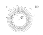
- the crystalline radical polymerizable composition for fixing the magnet of the rotary electric machine rotor core of the present invention fixes the magnet inserted in the magnet accommodating portion provided in the rotor core of the rotary electric machine formed of the laminated steel plate and the laminated steel plate.
- a crystalline radical polymerizable composition which is a crystalline radical polymerizable composition.
- the crystalline radical polymerizable composition contains at least a crystalline radical polymerizable compound A, an inorganic filler B, a silane coupling agent C, and a radical polymerization initiator D.
- the crystalline radically polymerizable compound A is solid at 23 ° C. and has the property of imparting fluidity by heating.
- the inorganic filler B is contained in an amount of 50 to 90% by mass based on the total amount of the crystalline radically polymerizable composition.
- the melt viscosity of the crystalline radically polymerizable composition measured by an enhanced flow tester is 500 Pa ⁇ s or more at 90 ° C. and a shear rate of 1 / s. It is characterized by that.
- the crystalline radical polymerizable composition for fixing a magnet of a rotary electric rotor core of the present invention, has a melt viscosity of 90 ° C. and sheared as measured by an enhanced flow tester. It is characterized in that it is 100 Pa ⁇ s or less at a speed of 250 / s.
- B) is in the range of 10 to 100.
- the inorganic filler B is characterized by containing at least amorphous spherical silica.
- the content of the amorphous spherical silica is 50 to 100% by mass with respect to the inorganic filler B. It is characterized by being.
- the crystalline radical polymerizable composition for fixing a magnet of the rotary electric rotor core of the present invention, is characterized by containing a lubricant E.
- the rotary electric rotor core of the present invention is a rotary electric rotor core in which a magnet is fixed by using the crystalline radical polymerizable composition for fixing the rotary electric rotor core magnet of the present invention.
- the method for manufacturing the rotary electric rotor core of the present invention uses the crystalline radical polymerizable composition for fixing the rotary electric rotor core magnet of the present invention, and injection is performed by an injection molding method, a transfer molding method, or a casting method. It is characterized by having a step of injecting a crystalline radical polymerizable composition having fluidity by heating into a magnet accommodating portion provided in a rotor core of a rotary electric machine formed of a laminated steel plate by a molding method.
- the crystalline radically polymerizable composition for fixing a magnet of a rotary electric rotor core of the present invention has an effect of being excellent in handleability at around room temperature and excellent in flow characteristics from an injection step to a curing step, and is cured. Since the product has excellent strength and good filling property, it can contribute to the production of a high-performance rotary electric rotor core.
- fixing means not moving from one place and not moving.
- Fixing includes adhesion and sealing, and fixing uses include adhesion and sealing.
- Fixing using the present crystalline radical polymerizable composition for fixing electrical and electronic parts can fix a part and / or all of the device to be fixed and / or the parts.
- the crystalline radically polymerizable composition for fixing a magnet of a rotary electric machine rotor core of the present invention is crystalline to fix a magnet inserted in a magnet accommodating portion provided in a rotor core of a rotary electric machine formed of a laminated steel plate and the laminated steel plate.
- a radically polymerizable composition contains at least a crystalline radical polymerizable compound A, an inorganic filler B, a silane coupling agent C, and a radical polymerization initiator D.
- the crystalline radically polymerizable compound A is solid at 23 ° C. and has the property of imparting fluidity by heating.
- the inorganic filler B is contained in an amount of 50 to 90% by mass based on the total amount of the crystalline radically polymerizable composition.
- the melt viscosity of the crystalline radically polymerizable composition measured by an enhanced flow tester is 500 Pa ⁇ s or more at 90 ° C. and a shear rate of 1 / s. It is characterized by that. This is because the use of the crystalline radical polymerizable composition makes it possible to realize a polymerizable composition having excellent flow characteristics and handleability, as shown in Examples described later.
- the crystalline radical polymerizable compound A includes crystalline unsaturated polyester, crystalline epoxy (meth) acrylate, crystalline urethane (meth) acrylate, crystalline polyester (meth) acrylate, and crystalline polyether (meth). ) One or more selected from acrylate and the like can be included.
- these crystalline radically polymerizable compounds A the handleability of the crystalline radically polymerizable composition of the present invention at around room temperature is improved.
- the mechanical properties of the cured product of the crystalline radically polymerizable composition of the present invention are also improved.
- These compounds are preferably crystalline compounds. Further, these compounds need to be compounds having a property of imparting fluidity by heating.
- the crystalline compound is a compound having a melting point, and may be a compound having a glass transition point and a melting point. These temperatures can be confirmed by a thermal analyzer such as DSC (Differential Scanning Calorimeter) or TGDTA (Differential Thermal Weight Simultaneous Measuring Device).
- a thermal analyzer such as DSC (Differential Scanning Calorimeter) or TGDTA (Differential Thermal Weight Simultaneous Measuring Device).
- the melting point of the crystalline radically polymerizable compound A is preferably 30 ° C. or higher, more preferably 40 ° C. or higher. It is preferably 50 ° C. or higher, more preferably 150 ° C. or lower, more preferably 140 ° C. or lower, and even more preferably 130 ° C. or lower. Crystalline radical polymerizable having a melting point in the range of 30 to 150 ° C. as compared with the case of using a crystalline radical polymerizable compound having a melting point of less than 30 ° C.
- crystalline radical polymerizable compound A having a melting point higher than 150 ° C. This is because better handleability can be achieved by using the compound A.
- the melting point of the crystalline radical polymerizable compound A is lower than the above range, the crystalline radical polymerizable composition tends to be liquid at room temperature, which may make it difficult for the crystalline radical polymerizable composition to maintain a solid state.
- the melting point of the crystalline radically polymerizable compound A is higher than the above range, the curing temperature and the plasticizing temperature, which will be described later, are close to each other, so that there is a risk of thickening during melt storage during injection.
- the viscosity of the crystalline radical polymerizable composition containing the crystalline radical polymerizable compound A sharply decreases at a temperature equal to or higher than the melting point of the crystalline radical polymerizable compound A, a composition having a low melt viscosity can be obtained.
- the amorphous radical polymerizable composition containing no crystalline radical polymerizable compound does not have a melting point, its viscosity gradually decreases as the temperature of the composition rises. Since the temperature may be raised to a temperature higher than necessary in order to reduce the amorphous radical polymerizable composition to a desired viscosity, the curing temperature and the plasticizing temperature are close to each other as described above, and the production stability is lowered. There is a risk of
- blending a crystalline radical polymerizable compound having a melting point of more than 150 ° C. as a part of the crystalline radical polymerizable compound A of the present invention is not excluded as long as the object of the present invention is not impaired.
- the crystalline radical polymerizable composition is preferably solid at 23 ° C. and more preferably solid at 35 ° C. from the viewpoint of handleability.
- the above range is set so that the shape of the composition does not change under the manufacturing, molding, transportation, and storage environments of the crystalline radical polymerizable composition, so that continuous production is possible under general-purpose manufacturing equipment and conditions. This is because it is easy to transport and store.
- the term "solid” refers to a solid whose shape and volume do not easily change due to an external force, and it is preferable that the measured value of hardness described in the section of Examples of the present specification is 5 or more. ..
- the inorganic filler B one having an average particle size of 100 ⁇ m or less, preferably 0.01 to 50 ⁇ m, can be used.
- the content of the inorganic filler B is preferably 50% by mass or more, more preferably 55% by mass or more, and more preferably 60% by mass or more, based on the total amount of the crystalline radically polymerizable composition. It is more preferable that it is 90% by mass or less.
- the crystalline radical polymerizable composition of the present invention filled in the magnet accommodating portion of the rotary electric rotor core is set in the above range from the injection step and the injection step.
- the radical may flow out to the outside of the magnet accommodating portion and adversely affect the product quality such as improper fixing of the magnet. This is because the melt viscosity at the time of injecting the crystalline radical polymerizable composition of the present invention into the magnet accommodating portion becomes high, so that a load is applied to the rotor core of the rotary electric machine, which may cause deformation or damage to the rotor core of the rotary electric machine.
- the inorganic filler B is amorphous from the viewpoint of mechanical strength of the cured product and fluidity at the time of injection. It preferably contains spherical silica.
- the amorphous spherical silica is preferably 50% by mass or more, more preferably 55% by mass or more, and further preferably 60% by mass or more, based on the total amount of the inorganic filler B.
- the melt viscosity of the crystalline radically polymerizable composition of the present invention measured by an enhanced flow tester is preferably 500 Pa ⁇ s or more, more preferably 700 Pa ⁇ s or more at 90 ° C. and a shear rate of 1 / s. Is. If it is lower than the above range, the crystalline radically polymerizable composition of the present invention is laminated to form a rotor core in the filling step and / or the transition step from the injection step to the curing step and / or the curing step. Since the composition does not penetrate into the gaps between the electromagnetic steel sheets and the composition retains its shape even during the transfer process to the curing step, it does not drip and can have good product quality.
- the ratio of the crystalline radical polymerizable compound A to the total amount of the crystalline and amorphous radical polymerizable compounds is preferably 30% by mass or more, more preferably 35% by mass or more, and 40% by mass or more. It is more preferable to have.
- the above range is defined as when the proportion of the crystalline radically polymerizable compound A is smaller than the above range, the crystalline radically polymerizable composition of the present invention becomes a paste or clay at around room temperature and is easy to handle. May be inferior to.
- the weight average of the crystalline radical polymerizable compound A from the viewpoint of quality control of the crystalline radical polymerizable composition.
- the molecular weight is preferably 100,000 or less, more preferably 50,000 or less, and even more preferably 30,000 or less.
- the molecular weight of the crystalline radically polymerizable composition cannot be controlled with high accuracy, so that the compound characteristics and the composition characteristics may fluctuate.
- the crystalline radical polymerizable composition facilitates the injection step of the crystalline radical polymerizable composition of the present invention.
- the melt viscosity of the crystalline radically polymerizable composition measured by the high-grade flow tester is preferably 100 Pa ⁇ s or less, more preferably 75 Pa ⁇ s or less at 90 ° C. and a shear rate of 250 / s. .. The above range is set so that the rotor core may be deformed when the injection pressure of the crystalline radical polymerizable composition is increased.
- the crystalline radical polymerizable composition measured by an enhanced flow tester from the viewpoint of fluidity balance.
- the melt viscosity quotient (A) / (B) is in the range of 10 to 100. Within the above range, continuous production is possible without the need to provide a cooling process during rotor core production, and fluidity during injection into the rotor core magnet housing can be ensured.
- B Melt viscosity at shear rate 250 / s
- the crystalline radical is described from the viewpoint of reliability of the crystalline radical polymerizable composition to the magnet and the magnet accommodating portion.
- the polymerizable composition is characterized by containing a radical E.
- the lubricant E can be preferably 0.1 to 5% by mass, more preferably 0.3 to 3% by mass, based on the total amount of the crystalline radically polymerizable composition.
- the crystalline radical polymerizable composition is imparted with slipperiness, and the crystalline radical polymerizable composition can be easily filled in the gap between the magnet and the rotor core magnet accommodating portion of the rotating electric machine, so that the magnet fixing force is improved. Can increase reliability.
- the shape of the granules of the crystalline radically polymerizable composition for fixing magnets of the rotary electric rotor core of the present invention is not particularly limited, but may be granular, powdery, tablet-like, or a mixture of one or more of them. It is preferable to have.
- the rotary electric rotor core of the present invention is characterized in that a magnet is fixed by using the crystalline radical polymerizable composition for fixing the rotary electric rotor core magnet of the present invention.
- the fixing method is not particularly limited by a conventional method, and is not particularly limited as long as the crystalline radical polymerizable composition for fixing a rotary electric rotor core magnet of the present invention is used.
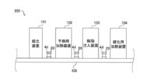
- the method for producing a rotary electric rotor core of the present invention is a step of injecting the crystalline radical polymerizable composition of the present invention, which has been imparted with fluidity by heating, into a magnet accommodating portion provided in the rotary electric rotor core formed of a laminated steel plate. Manufactured through.
- the injection is preferably carried out by an injection molding method, a transfer molding method, or an insert molding method by a casting method.
- the method of fixing the magnet of the rotor core with resin is not particularly limited by the conventional method.
- various known core pressing means and resin injection means can be applied.
- the core pressing means pressing with a mold of a resin injection device and pressing with a jig can be mentioned.
- the resin injection means a transfer molding machine, an injection molding machine and the like can be mentioned.
- the core pressing method and various resin injection devices may be combined for production.
- the jig pressing means and the injection molding machine are used in combination, but the present invention is not limited to this.
- a combination of the mold pressing means and the transfer molding machine a combination of the jig pressing means and the transfer molding machine, or a combination of the mold pressing means and the injection molding machine, etc.
- the unsaturated polyester used in the present invention can be obtained, for example, by performing a known dehydration condensation reaction between an unsaturated polybasic acid or a saturated polybasic acid and glycols. Usually, it can have an acid value of 2-40 mg-KOH / g.
- the crystalline property is obtained by appropriately selecting the selection and combination of unsaturated polybasic acid and acid components of saturated polybasic acid, the selection and combination of glycols, and the blending ratio thereof. It is possible to obtain an unsaturated polyester which is solid and has the property of imparting fluidity by heating.
- unsaturated polybasic acids include maleic acid, maleic anhydride, fumaric acid, citraconic acid, mesaconic acid, itaconic acid, tetrahydrophthalic acid, and glutaconic acid.
- Saturated polybasic acids include phthalic acid, phthalic anhydride, isophthalic acid, terephthalic acid, succinic acid, adipic acid, sebatic acid, azelaic acid, tetrahydrophthalic anhydride, methyltetrahydrophthalic anhydride, endomethylenetetrahydrophthalic anhydride, Examples thereof include het acid, tetrabrom phthalic anhydride and the like.
- Glycols include ethylene glycol, 1,3-propanediol, 1,4-butanediol, 1,5-pentanediol, 1,6-hexanediol, 1,8-octanediol, propylene glycol, diethylene glycol, and triethylene glycol.
- the unsaturated polyesters it is preferable to use fumaric acid as the unsaturated polybasic acid, isophthalic acid or terephthalic acid as the saturated polybasic acid, and ethylene glycol as the main component as the glycol, 1,3.
- fumaric acid as the unsaturated polybasic acid
- isophthalic acid or terephthalic acid as the saturated polybasic acid
- ethylene glycol as the main component as the glycol, 1,3.
- An unsaturated polyester using -propanediol, 1,4-butanediol, 1,5-pentanediol, 1,6-hexanediol, 1,8-octanediol, and cyclohexanedimethanol is preferable.
- the epoxy (meth) acrylate used in the present invention can be produced by a method known per se. It can be obtained by reacting an epoxy resin with an unsaturated monobasic acid in the presence or absence of a known polymerization inhibitor and a known esterification catalyst, in an inert gas stream or in an air atmosphere. By appropriately selecting an epoxy resin and an unsaturated monobasic acid, it is possible to obtain an epoxy (meth) epoxy acrylate which is solid at 23 ° C. and has crystallization having a property of imparting fluidity by heating. If necessary, another radically polymerizable compound or an organic solvent can be added for the purpose of lowering the melt viscosity of the reaction system for the reaction.
- the epoxy (meth) acrylate in the present invention is, for example, a double acrylate or methacrylate at the molecular terminal obtained by addition-reacting acrylic acid or methacrylic acid to an epoxy resin having two or more glycidyl ether groups in one molecule. It can be an epoxy (meth) acrylate having a bond.
- An epoxy (meth) acrylate resin in which an epoxy (meth) acrylate is dissolved in a radically polymerizable compound may be used.
- the epoxy resin having two or more glycidyl ether groups in one molecule is, for example, bisphenol A, bisphenol F, bisphenol S, or the like, or a bisphenol type epoxy resin from these derivatives, bixirenol and bixilenol from a derivative thereof.
- examples thereof include type epoxy resins, biphenol type epoxy resins from biphenols and derivatives thereof, naphthalene type epoxy resins from naphthalene and its derivatives, and epoxy resins such as novolak type epoxy resins, which may be used alone or in combination of two or more. Can be mixed and used.
- the epoxy equivalent which is a measure of the molecular weight of the epoxy resin, is preferably 174 to 2,000 eq / g.
- the urethane (meth) acrylate in the present invention is, for example, a polyalcohol having two or more hydroxyl groups in one molecule and / or a polyester polyol and / or a molecular-terminated isocyanate obtained by reacting a polyether polyol with a diisocyanate, and /.
- one or more isocyanates in one molecule are reacted with an alcoholic hydroxyl group and a compound having one or more acrylate groups or methacrylate groups, or first, a compound having an alcoholic hydroxyl group and one or more acrylate groups or methacrylate groups.
- diisocyanate are reacted so that an isocyanate group remains, and the remaining isocyanate group is reacted with a polyalcohol and / or a polyester polyol and / or a polyether polyol having two or more hydroxyl groups in one molecule.
- It can be a urethane acrylate having a double bond of acrylate or methacrylate at the end.
- urethane (meth) acrylate a combination of isocyanate, polyalcohol and / or polyester polyol and / or polyether polyol, and a compound having an alcoholic hydroxyl group and one or more acrylate groups or methacrylate groups should be appropriately selected.
- a urethane (meth) epoxy acrylate having crystallinity A urethane (meth) acrylate resin in which urethane acrylate or urethane methacrylate is blended with a radically polymerizable compound such as styrene or diethylene glycol dimethacrylate may be used. These can be used alone or in mixtures of two or more. By appropriately adjusting the constituent components of these compounds, they can be made solid at 23 ° C. and have the property of being able to impart fluidity by heating.
- Examples of the compound having an alcoholic hydroxyl group and one or more acrylate groups or methacrylate groups include hydroxyethyl (meth) acrylate, 2-hydroxypropyl (meth) acrylate, 2-hydroxybutyl (meth) acrylate, and phenoxyhydroxypropyl (meth).
- Acrylate, trimethylolpropandi (meth) acrylate, dipropylene glycol mono (meth) acrylate and the like can be used.
- the polyalcohol having two or more hydroxyl groups in one molecule includes, for example, neopentyl glycol, ethylene glycol, 1,3-propanediol, 1,2-butanediol, 1,3-butanediol, and 1, , 4-butanediol, 1,5-pentanediol, 1,6-hexanediol, 1,7-heptandiol, 1,8-octanediol, 1,9-nonanediol, 1,10-decanediol, propylene Glycol, diethylene glycol, dipropylene glycol, trimethylene glycol, hydrogenated bisphenol A, bisphenol A ethylene oxide adduct, bisphenol A propylene oxide adduct, etc.
- polyester polyol having two or more hydroxyl groups in one molecule.
- Polyalcohols such as neopentyl glycol, ethylene glycol, propylene glycol, diethylene glycol, dipropylene glycol, trimethylene glycol, hydrogenated bisphenol A, bisphenol A ethylene oxide adduct, bisphenol A propylene oxide adduct, and adipic acid, (anhydrous)
- polyether polyol examples include polyethylene glycol having a molecular weight of 300 to 2,000 obtained by the ring-opening reaction of ethylene oxide or propylene oxide, polypropylene glycols, polycaprolactone obtained by the ring-opening reaction of caprolactone, or the like. The above can be used in combination.
- aromatic and / or aliphatic polyisocyanate compounds are used, for example, tolylene diisocyanate, diphenylmethane diisocyanate, hydrogenated diphenylmethane diisocyanate, 1,6-hexa.
- the polyester (meth) acrylate in the present invention is, for example, an acrylate at the molecular terminal obtained by esterification of a polyester polyol with acrylic acid or methacrylic acid, or a reaction between an acid-terminated polyester and an acrylate or methacrylate having a glycidyl group.
- polyester acrylate having a double bond of methacrylate, or polyester methacrylate can be mentioned.
- polyester (meth) acrylate In the production of polyester (meth) acrylate, crystalline polyester (meth) acrylate can be obtained by appropriately selecting polyester polyol and acrylic acid or methacrylic acid, or acid-terminated polyester and acrylate or methacrylate having a glycidyl group. .. It may be a polyester acrylate resin in which polyester acrylate or polyester methacrylate is blended with a radically polymerizable compound such as styrene or diethylene glycol dimethacrylate, or a polyester methacrylate resin. These can be used alone or in mixtures of two or more. By appropriately adjusting the constituent components of these compounds, they can be made solid at 23 ° C. and have the property of being able to impart fluidity by heating.
- the polyether (meth) acrylate in the present invention is, for example, a molecule obtained by esterifying a polyether polyol with acrylic acid or methacrylic acid, or reacting an acid-terminated polyether with an acrylate or methacrylate having a glycidyl group. It can be a polyether acrylate having a double bond of acrylate or methacrylate at the end, or a polyether methacrylate.
- a crystalline polyester (meth) acrylate is obtained by appropriately selecting a polyether polyol and acrylic acid or methacrylic acid, or an acid-terminated polyester and an acrylate or methacrylate having a glycidyl group. Can be done. It may be a polyether acrylate resin in which a polyether acrylate or a polyether methacrylate is dissolved in a radical compound such as styrene or diethylene glycol dimethacrylate, or a polyether methacrylate resin. These can be used alone or in mixtures of two or more. By appropriately adjusting the constituent components of these compounds, they can be made solid at 23 ° C. and have the property of being able to impart fluidity by heating.
- ethoxylated isocyanuric acid triacrylate (melting point about 50 ° C.), polyethylene glycol di (meth) acrylate (melting point 35 to 53 ° C.), methoxypolyethylene glycol (meth). ) Acrylate (melting point 33-40 ° C), behenyl acrylate (melting point 46 ° C), tetramethylpiperinidyl methacrylate (melting point 56-60 ° C), trimetalyl isocyanurate (melting point 83-87 ° C), diacetoneacrylamide (melting point approx.
- a radically polymerizable compound that is liquid at room temperature can be blended as a part of the crystalline radically polymerizable composition in the present invention as long as the object of the present invention is not impaired.
- vinyl aromatic compounds such as styrene monomer having a vinyl group, ⁇ -methylstyrene, vinyltoluene, ⁇ -chlorostyrene; vinyl acetate, vinyl propionate, vinyl lactate, vinyl butyrate, Beova monomer (manufactured by Shell Chemical Co., Ltd.), etc.
- Vinyl esters (meth) acrylic acid esters such as methyl acrylate, ethyl acrylate, n-butyl acrylate, methyl methacrylate, ethyl methacrylate, n-butyl methacrylate and the like can be mentioned.
- Bifunctionals such as triallyl cyanurate, diethylene glycol dimethacrylate, diallyl tetrabromphthalate, phenoxyethyl acrylate, 2-hydroxyethyl acrylate, 1,6-hexanediol diacrylate, diallyl phthalate having an allyl group, and triallyl isocyanurate.
- a radically polymerizable compound having the above radically polymerizable group can be used. These radically polymerizable compounds may be used alone or in combination of two or more.
- radically polymerizable compound in the present invention for example, diallyl phthalate prepolymer, Tyke prepolymer (manufactured by Shinryo Co., Ltd.), epoxy prepolymer, urethane prepolymer, and acrylate prepolymer can be used.
- diallyl phthalate prepolymer Tyke prepolymer (manufactured by Shinryo Co., Ltd.)
- epoxy prepolymer urethane prepolymer
- acrylate prepolymer acrylate prepolymer
- Inorganic filler B can be blended in the crystalline radical polymerizable composition for fixing magnets of the rotary electric rotor core of the present invention.
- examples of the inorganic filler B include calcium carbonate, magnesium carbonate, barium carbonate, calcium hydroxide, aluminum hydroxide, magnesium hydroxide, magnesium oxide, alumina, silica, zinc oxide, mica, aluminum nitride, and boron nitride.
- silica is preferable, and amorphous spherical silica is more preferable, from the viewpoint of mechanical strength of the molded product of the crystalline radical polymerizable composition of the present invention. These may be used alone or in combination of two or more.
- silane coupling agent C has an effect of improving the adhesion between the inorganic filler B and the reinforcing material described later and other components.
- silane coupling agent for example, epoxysilane-based, aminosilane-based, cyanicsilane-based, vinylsilane-based, acrylicsilane-based, mercaptosilane-based, and composite systems thereof and the like can be used.
- an acrylic silane coupling agent is preferable from the viewpoint of improving the strength of the cured product of the crystalline radical polymerizable composition of the present invention.
- the crystalline radical polymerizable composition for fixing magnets of the rotary electric rotor core of the present invention has an effect of improving the adhesion between various additives such as an inorganic filler and a reinforcing material described later and other components (meth).
- Coupling agents other than acrylate compounds and silane coupling agents can be blended.
- the (meth) acrylate compound having a polar group is not particularly limited, and examples thereof include a (meth) acrylate compound in which a substituent containing an atom other than carbon and hydrogen is ester-bonded, and examples of the substituent include a hydroxyl group and an epoxy.
- examples thereof include a group, a glycidyl ether group, a tetrahydrofurfuryl group, an isocyanate group, a carboxyl group, an alkoxysilyl group, a phosphate ester group, a lactone group, an oxetane group, a tetrahydropyranyl group, an amino group and the like.
- the coupling agent is not particularly limited, and for example, a silane-based coupling agent, a titanate-based coupling agent, or the like can be used.
- various adhesion imparting agents for improving adhesion to a resin substrate or metal can be blended.
- the adhesion-imparting agent for improving the adhesion to the resin substrate or metal is not particularly limited, but for example, rosin-based resin, terpene-based resin, alkylphenol resin, xylene resin, benzotriazole-based resin, triazine-based resin, and phosphoric acid.
- examples include ester compounds, alcohol compounds, and coupling agents.
- the radical polymerization initiator D an unsaturated polyester resin composition or a heat-decomposable organic peroxide usually used in a radically polymerizable composition is used. Oxides can be used.
- organic peroxides include t-butylperoxy-2-ethylhexyl monocarbonate, 1,1-di (t-hexylperoxy) cyclohexane, and 1,1-di (t-butylperoxy) -3,3.
- examples thereof include 5-trimethylcyclohexane, t-butylperoxyoctate, benzoyl peroxide, methyl ethyl ketone peroxide, acetylacetone peroxide, t-butylperoxybenzoate, and dicumyl peroxide. These may be used alone or in combination of two or more.
- an organic peroxide having a 10-hour half-life temperature of 100 ° C. or higher it is preferable to use an organic peroxide having a 10-hour half-life temperature of 100 ° C. or higher, and specifically, dicumyl peroxide can be preferably used.
- a peroxide having a low half-life temperature of 10 hours the plasticization temperature and the curing temperature are close to each other when the crystalline radical polymerizable composition is plasticized in the cylinder in the injection molding method. There is a risk that the curing reaction will partially proceed in the cylinder and the injection stability will be poor.
- a polymerization inhibitor can be blended.
- the polymerization inhibitor include hydroquinone, monomethyl ether hydroquinone, toluhydroquinone, di-t-4-methylphenol, monomethyl ether hydroquinone, phenothiazine, t-butylcatechol, parabenzoquinone, quinones such as pyrogallol, and 2,6-di-t.
- Phenolic compounds such as butane, 4-hydroxy-2,2,6,6-tetramethylpiperidine 1-oxyl, 4-oxo-2,2,6,6-tetramethylpiperidine-1-oxyl, 4-methoxy -2,2,6,6-tetramethylpiperidin-1-oxyl, 4-carboxy-2,2,6,6-tetramethylpiperidin-1-oxyl, 2,2,6,6-tetramethylpiperidine-1 -Piperidin such as oxyl-1-oxyls can be mentioned.
- thickening during filling during molding can be suppressed, and a crystalline radical polymerizable composition having a low melt viscosity can be obtained.
- a reinforcing material can be blended. By using a reinforcing material, it may be possible to obtain a cured product having even better strength characteristics and dimensional stability.
- glass fibers used for fiber reinforced plastics such as BMC (bulk molding compound) and SMC (sheet molding compound) can be usually used, but glass fibers can be used. Others can be used without being limited to.
- Glass fibers include silicate glass, E glass (non-alkali glass for electricity), C glass (alkali-containing glass for chemicals), A glass (acid resistant glass), and S glass (high-strength glass) made from silicate glass. Glass fibers such as, etc. can be mentioned, and those made into long fibers (roving), short fibers (chopped strands), and milled fibers can be used. Further, as these glass fibers, those which have been subjected to surface treatment can also be used.
- the crystalline radical polymerizable composition for fixing magnets of the rotary electric rotor core of the present invention other inorganic fillers are appropriately blended as long as the fluidity of the composition and the characteristics when used as a fixing material are not impaired. Can be done.
- Examples of these include oxides and their hydrates, inorganic foamed particles, hollow particles such as silica balloons, and the like.
- the lubricant E can be used in the crystalline radically polymerizable composition for fixing a magnet of the rotary electric rotor core of the present invention.
- the lubricant is a fatty acid-based, fatty acid metal salt-based, or mineral-based wax that is generally used as a mold release agent for thermosetting resins. Waxes can be preferably used.
- lubricants include stearic acid, zinc stearate, aluminum stearate, calcium stearate, paraffin wax and the like. These lubricants may be used alone or in combination of two or more.
- a curing catalyst in addition to these compounding components, a curing catalyst, a polymerization inhibitor, a colorant, a thickener, a wet dispersant, and a surface adjustment for adjusting the curing conditions of the crystalline radical polymerizable composition of the present invention.
- Agents, thickeners, flow modifiers, other organic additives, inorganic additives and the like can be appropriately blended as needed.
- the crystalline radically polymerizable composition for fixing magnets of the rotary electric rotor core of the present invention is a kneader and an extruder capable of heating and pressurizing after mixing each component and mixing them sufficiently uniformly using a mixer, a blender or the like. It can be prepared by, etc., granulated and manufactured.
- Examples 1 to 4 and Comparative Example 1 The crystalline radically polymerizable compositions of Examples 1 to 4 shown in Table 2 and the amorphous radically polymerizable compositions of Comparative Example 1 shown in Table 3 are blended in the amounts shown in Tables 2 and 3 below. After blending and uniformly preparing using a kneader capable of heating and cooling under pressure, the preparation was put into an extruder and hot-cut to obtain granules. Some granular and massive radically polymerizable compositions were powdered using a pulverizer.
- Radical polymerizable compound 1 Urethane Methacrylate (2-Hydroxyethyl methacrylate adduct of 1,6-hexamethylene diisocyanate) 2.
- Crystalline Radical Polymerizable Compound 2 Ethoxylated Isocyanuric Acid Triacrylate (A-9300, manufactured by Shin-Nakamura Chemical Co., Ltd.) 3.
- Acrylic radically polymerizable compound 3 Bisphenol A type epoxy acrylate (Acrylic acid adduct of bisphenol A type epoxy Epoxy equivalent 450 g / eq.)
- Inorganic filler 1 Fused silica (Made by Denka Co., Ltd., average particle size 24 ⁇ m) 2.
- Inorganic filler 2 Magnesium oxide (Made by Ube Material Industries Ltd., average particle size 70 ⁇ m)
- Silane coupling agent methacryl-based silane (KBM-503 manufactured by Shin-Etsu Chemical Co., Ltd.) 2. Radical polymerization initiator: Dicumyl peroxide (Park Mill D manufactured by NOF CORPORATION) 3. 3. Lubricants: Zinc stearate (GF-200 manufactured by NOF CORPORATION) 4. Polymerization inhibitor: Parabenzoquinone (PBQ manufactured by Seiko Kagaku Co., Ltd.) 5. Colorant: Carbon black (CB40 manufactured by Mitsubishi Chemical Corporation)
- JIS K 7215 was used as a reference for the hardness measurement method.
- the hardness of the crystalline radical-polymerizable compositions of Examples 1 to 4 shown in Table 2 and the amorphous radical-polymerizable composition of Comparative Example 1 shown in Table 3 was measured by a durometer (West Tokyo Seimitsu Co., Ltd. WR-105D). ).
- the radically polymerizable composition whose temperature was adjusted to 90 ° C. was formed into a flat plate of about 100 mm ⁇ 100 mm ⁇ 10 mm and cooled and solidified in a thermostatic chamber at 23 ° C.
- the pressure reference surface of the durometer is pressed against the surface of the radically polymerizable composition as quickly as possible without impact while keeping parallel to the surface of the radically polymerizable composition. was well adhered. Within 1 second, the maximum indicated value of the pointer of the indicator was read promptly.
- the results are shown in Tables 2 and 3.
- the target hardness was excellent at 30 or more and acceptable at 20 or more. However, even if the above strict standards are not cleared, the conditions of less than 20 may be met depending on the desired application, required quality, etc., so it may be considered as a guideline.
- the target melt viscosity at a shear rate of 1 / s was 500 Pa ⁇ s or more, 700 Pa ⁇ s or more was excellent, and 500 Pa ⁇ s or more was acceptable.
- melt viscosity at the target shear rate of 250 / s was 100 Pa ⁇ s or less, 80 Pa ⁇ s or less was excellent, and 100 Pa ⁇ s or less was acceptable.
- the conditions may be met other than 100 depending on the desired application, required quality, etc., so it may be considered as a guideline.
- the crystalline radically polymerizable composition for fixing a rotary electric rotor core magnet in the present invention is solid at room temperature, so that it is easy to handle near room temperature, and a magnet is inserted in the magnet insertion hole. Even if a molten crystalline radical polymerizable composition is injected after insertion, it does not penetrate into the gaps between the laminated electromagnetic steel sheets constituting the rotor core, and does not drip during the transfer process to the curing process. It turned out to be excellent in rotor core productivity. It was found that the crystalline radically polymerizable composition for fixing electrical and electronic components in the present invention shows excellent results as a whole.
- Comparative Example 1 is an amorphous radical polymerizable composition in which the crystalline radical polymerizable compound of Example 1 was changed to an amorphous radical polymerizable compound and the amount of the inorganic filler compounded was reduced. Comparative Example 1 was a solid and had a low melt viscosity at 250 / s, but the melt viscosity at 1 / s was also low, resulting in poor retention of the polymerizable composition.
- the crystalline radically polymerizable composition of the present invention is excellent in flow characteristics and handleability.
- Example 8 Next, using the crystalline radical polymerizable composition for fixing the magnet of the rotary electric rotor core of the present invention, a rotary electric rotor core in which the magnet was actually fixed was manufactured. (Rotor core structure) First, the structure of the rotor core 4 of the present embodiment will be described with reference to FIG.
- the rotary electric machine 100 includes a rotor 1 (rotor core 4) and a stator 2.
- the rotor 1 and the stator 2 are each formed in an annular shape.
- the rotor 1 is arranged so as to face the inside (R1 side) of the stator 2 in the radial direction (R direction). That is, the rotary electric machine 100 is configured as an inner rotor type rotary electric machine.
- the shaft 3 is arranged inside (R1 side) in the radial direction (R direction) of the rotor 1.
- the shaft 3 is connected to an engine or an axle via a rotational force transmitting member such as a gear.
- the rotary electric machine 100 is configured as a motor, a generator, or a motor / generator, and is configured to be mounted on a vehicle.
- the stator 2 includes a stator core 2a and a coil 2b arranged on the stator core 2a.
- the stator core 2a is configured such that, for example, a plurality of electromagnetic steel sheets (silicon steel sheets) are laminated in the axial direction (Z direction) so that magnetic flux can pass through the stator core 2a.
- the coil 2b is connected to an external power supply unit and is configured to supply electric power (for example, three-phase alternating current electric power).
- the coil 2b is configured to generate a magnetic field when electric power is supplied.
- the rotor 1 and the shaft 3 are configured to rotate with respect to the stator 2 as the engine or the like is driven even when electric power is not supplied to the coil 2b.
- the coil 2b is arranged over the entire circumference of the stator core 2a.
- the rotor core 4 includes a laminated core 4d (see FIG. 2) and a permanent magnet 5.
- a laminated core 4d In the laminated core 4d, a plurality of electromagnetic steel plates 4a (see FIG. 2) are laminated in a direction (Z direction) along the rotation axis A of the rotor core 4 (laminated steel plate), and in the laminated direction (Z direction) of the electromagnetic steel plates 4a. It has a magnet accommodating portion 10 extending to.
- the permanent magnet 5 has a rectangular cross section orthogonal to the axial direction (Z direction) of the laminated core 4d (rotor core 4). For example, the permanent magnet 5 is configured so that the magnetization direction (magnetization direction) is the lateral direction.
- the permanent magnet 5 is inserted into the magnet accommodating portion 10 of the laminated core 4d.
- a plurality of magnet accommodating portions 10 (32 in the rotor core 4) are provided in the laminated core 4d. That is, the rotary electric machine 100 is configured as an embedded permanent magnet type motor (IPM motor: Interior Permanent Magnet Motor).
- the magnet accommodating portion 10 is arranged on the outer side (R2 side) of the laminated core 4d (rotor core 4) in the radial direction (R direction). Further, the two magnet accommodating portions 10 adjacent to each other are arranged in a V shape. The arrangement of the magnet accommodating portion 10 is not limited to this.
- the rotor core 4 includes a resin material 6 (see FIG. 2) filled in the magnet accommodating portion 10.
- the composition of the present invention can be used as the resin material 6.
- the resin material 6 is provided so as to fix the permanent magnet 5 arranged in the magnet accommodating portion 10.
- the resin material 6 is composed of a material (thermosetting resin) that melts at the first temperature T1 and cures at a second temperature T2 higher than the first temperature T1.
- the resin material 6 is solid (flake-like, pellet-like, powder-like, etc.) at room temperature lower than the first temperature T1, and is heated from room temperature so that the temperature of the resin material 6 becomes the first temperature. When it becomes T1 or more, it melts.
- the resin material 6 is configured to maintain a molten state (do not cure) in a state where the first temperature is T1 or higher and the second temperature is lower than T2.
- the resin material 6 is configured to be cured by being heated to a temperature equal to or higher than the second temperature T2. In FIG. 1, the resin material 6 is not shown for the sake of simplicity.
- the jig 20 includes an upper plate 21, a pressing spring 22, a pressing plate 23, a lower plate 24, a heat insulating member 25, a positioning plate 26, and a clamp member 27.
- the upper plate 21, the pressing plate 23, the lower plate 24, and the positioning plate 26 are each made of SUS (stainless steel).
- the upper plate 21 has a through hole 21a in the central portion and is formed in an annular shape.
- the upper plate 21 includes a plurality of resin injection holes 21b.
- the resin injection hole 21b is provided so that the mold nozzle of the resin injection device 103 can be inserted.
- the resin injection holes 21b are provided so as to overlap each of the plurality of magnet accommodating portions 10 (32 in the rotor core 4).
- the induction heating coil (not shown) of the preheating heating device 102 has a diameter of the laminated core 4d via each of the through hole 21a of the upper plate 21 and the through hole 23a of the pressing plate 23. It is inserted inside the direction (R direction) (R1 side).
- an induction heating coil (not shown) provided in the curing heating device 104 also has a laminated core via the through hole 21a of the upper plate 21 and the through hole 23a of the pressing plate 23. It is inserted inside (R1 side) in the radial direction (R direction) of 4d.
- the pressing spring 22 is provided between the upper plate 21 and the pressing plate 23. Further, a plurality of pressing springs 22 are provided at equal angular intervals along the circumferential direction (E direction) of the laminated core 4d when viewed from the direction (Z direction) along the rotation axis A.
- the jig 20 is provided with four pressing springs 22. Each of the plurality of pressing springs 22 is provided at a position where the laminated core 4d is arranged on the jig 20 and overlaps with the laminated core 4d when viewed from above (Z1 side).
- the pressing plate 23 has a through hole 23a in the central portion when viewed from the Z direction, and is formed in an annular shape. Further, the pressing plate 23 includes a plurality of resin injection holes 23b. The plurality of resin injection holes 23b are provided at positions that overlap with the plurality of resin injection holes 21b of the upper plate 21 when viewed from above (Z1 side).
- the laminated core 4d is arranged (mounted) on the lower plate 24. That is, the lower plate 24 is in contact with the lower end surface 4c of the laminated core 4d.
- the lower plate 24 has a through hole 24a in the center and is formed in an annular shape. Further, the lower plate 24 includes a plurality of notches 24b (three in the jig 20).
- the heat insulating member 25 is provided so as to be sandwiched between the lower plate 24 and the positioning plate 26.
- the heat insulating member 25 has a through hole 25a in the center and is formed in an annular shape. Further, the heat insulating member 25 is made of resin.
- the clamp members 27 are provided at substantially equal angular intervals (that is, 90 degree intervals) along the circumferential direction (C direction) of the laminated core 4d when viewed from the direction (Z direction) along the rotation axis A.
- the rotor core 4 manufacturing system 200 includes an assembly device 101, a preheating heating device 102, a resin injection device 103, and a curing heating device 104. Further, the rotor core 4 manufacturing system 200 includes a conveyor 105 for transporting the laminated core 4d.
- the assembly device 101, the preheating heating device 102, the resin injection device 103, and the curing heating device 104 are separate devices from each other.
- the assembly device 101 is configured to arrange (assemble) the laminated core 4d on the jig 20. Specifically, the assembly device 101 is configured to arrange the laminated core 4d on the jig 20 and arrange (insert) the permanent magnet 5 in the magnet accommodating portion 10.
- the preheating heating device 102 is configured to preheat by heating the laminated core 4d. Specifically, the preheating heating device 102 heats the laminated core 4d arranged on the jig 20 at a first temperature T1 (for example, 50 ° C.) or more and less than a second temperature T2 (for example, 120 ° C.). It is configured to be preheated by.
- the first temperature T1 is the temperature at which the resin material 6 melts (the temperature at which melting starts).
- the second temperature T2 is a temperature at which the resin material 6 is cured (thermosetting) (a temperature at which curing (thermosetting) is started) and is higher than the first temperature T1.
- the resin injection device 103 is configured to inject the resin material 6 into the magnet accommodating portion 10. Specifically, the resin injection device 103 is first placed in the magnet accommodating portion 10 in a state where the laminated core 4d is arranged in the jig 20 and in a state where the permanent magnet 5 is inserted in the magnet accommodating portion 10. It is configured to inject the resin material 6 melted at a temperature T1 or higher.
- the curing heating device 104 is configured to cure the resin material 6 in the magnet accommodating portion 10 by heating the laminated core 4d.
- the curing heating device 104 is the temperature at which the resin material 6 cures the laminated core 4d in a state where the resin material 6 is injected into the magnet accommodating portion 10 while being arranged on the jig 20. It is configured to cure the resin material 6 in the magnet accommodating portion 10 by heating at the second temperature T2 or higher.
- the rotor core 4 manufacturing system 200 includes a conveyor 105 for transporting the laminated core 4d.
- the rotary electric machine rotor core in which the magnet is fixed by using the crystalline radical polymerizable composition for fixing the magnet of the rotary electric machine rotor core of the present invention, the rotary electric machine rotor core is not deformed or the like. It turned out that it is possible to fix the magnet.
Landscapes
- Chemical & Material Sciences (AREA)
- Organic Chemistry (AREA)
- Medicinal Chemistry (AREA)
- Polymers & Plastics (AREA)
- Health & Medical Sciences (AREA)
- Chemical Kinetics & Catalysis (AREA)
- Engineering & Computer Science (AREA)
- Power Engineering (AREA)
- Manufacturing & Machinery (AREA)
- Macromonomer-Based Addition Polymer (AREA)
- Permanent Field Magnets Of Synchronous Machinery (AREA)
- Adhesives Or Adhesive Processes (AREA)
- Manufacture Of Motors, Generators (AREA)
- Compositions Of Macromolecular Compounds (AREA)
Abstract
La présente invention concerne une composition polymérisable par voie radicalaire cristalline pour fixer un aimant d'un noyau de rotor de machine dynamo-électrique, la composition présentant une excellente manipulation à une température presque normale, d'excellentes caractéristiques de fluidité de l'étape d'injection à l'étape de durcissement, et également une excellente résistance d'un matériau durci de celle-ci. La présente composition polymérisable par voie radicalaire cristalline pour fixer un aimant d'un noyau de rotor de machine dynamo-électrique est destinée à fixer, dans un noyau de rotor de machine dynamo-électrique formé à partir de plaques d'acier en couches, les plaques d'acier en couches et un aimant qui est inséré dans une partie de réception d'aimant disposée sur le noyau de rotor, la composition polymérisable par voie radicalaire cristalline étant caractérisée en ce que la composition polymérisable par voie radicalaire cristalline comprend au moins un composé polymérisable par voie radicalaire cristallin A, une charge inorganique B, un agent de couplage au silane C, et un initiateur de polymérisation radicalaire D, le composé polymérisable par voie radicalaire cristallin A ayant les caractéristiques d'être solide à 23 °C et en ce que le composé polymérisable par voie radicalaire cristallin A peut être rendu fluide par chauffage, la charge inorganique B étant comprise dans un rapport de 50 à 90 % en masse par rapport à la quantité totale de la composition polymérisable par voie radicalaire cristalline, et la viscosité à l'état fondu de la composition polymérisable par voie radicalaire cristalline étant de 500 Pa∙s ou plus à 90 °C et une vitesse de cisaillement de 1/s telle que mesurée à l'aide d'un testeur de flux de type Koka.
Priority Applications (3)
| Application Number | Priority Date | Filing Date | Title |
|---|---|---|---|
| US17/909,852 US20230082542A1 (en) | 2020-03-31 | 2021-03-29 | A crystalline radical polymerizable composition for fixing a magnet of a rotating electric machine rotor core, a rotating electric machine rotor core using the composition, and a method of manufacturing the rotating electric machine rotor core |
| CN202180026257.2A CN115397942A (zh) | 2020-03-31 | 2021-03-29 | 旋转电机转子芯的磁铁固定用结晶性自由基聚合性组合物、使用了该组合物的旋转电机转子芯、以及该旋转电机转子芯的制造方法 |
| EP21780466.5A EP4130183A4 (fr) | 2020-03-31 | 2021-03-29 | Composition polymérisable par voie radicalaire cristalline pour fixer un aimant d'un noyau de rotor de machine dynamo-électrique, noyau de rotor de machine dynamo-électrique utilisant ladite composition, et procédé de fabrication dudit noyau de rotor de machine dynamo-électrique |
Applications Claiming Priority (2)
| Application Number | Priority Date | Filing Date | Title |
|---|---|---|---|
| JP2020-061983 | 2020-03-31 | ||
| JP2020061983A JP2021161164A (ja) | 2020-03-31 | 2020-03-31 | 回転電機ロータコアの磁石固定用結晶性ラジカル重合性組成物、当該組成物を使用した回転電機ロータコア、及び当該回転電機ロータコアの製造方法 |
Publications (1)
| Publication Number | Publication Date |
|---|---|
| WO2021200817A1 true WO2021200817A1 (fr) | 2021-10-07 |
Family
ID=77928105
Family Applications (1)
| Application Number | Title | Priority Date | Filing Date |
|---|---|---|---|
| PCT/JP2021/013270 WO2021200817A1 (fr) | 2020-03-31 | 2021-03-29 | Composition polymérisable par voie radicalaire cristalline pour fixer un aimant d'un noyau de rotor de machine dynamo-électrique, noyau de rotor de machine dynamo-électrique utilisant ladite composition, et procédé de fabrication dudit noyau de rotor de machine dynamo-électrique |
Country Status (5)
| Country | Link |
|---|---|
| US (1) | US20230082542A1 (fr) |
| EP (1) | EP4130183A4 (fr) |
| JP (1) | JP2021161164A (fr) |
| CN (1) | CN115397942A (fr) |
| WO (1) | WO2021200817A1 (fr) |
Citations (5)
| Publication number | Priority date | Publication date | Assignee | Title |
|---|---|---|---|---|
| JP2016197995A (ja) | 2016-08-30 | 2016-11-24 | 住友ベークライト株式会社 | ロータ |
| JP2017186439A (ja) * | 2016-04-05 | 2017-10-12 | 株式会社スリーボンド | ラジカル硬化性樹脂組成物、モータ用接着剤組成物 |
| WO2018159387A1 (fr) * | 2017-03-03 | 2018-09-07 | 日本ユピカ株式会社 | Composition polymérisable par radicaux cristallins pour composant électrique/électronique, composant électrique/électronique moulé obtenu en utilisant ladite composition, et procédé de production dudit composant électrique/électronique moulé |
| WO2018164277A1 (fr) * | 2017-03-09 | 2018-09-13 | アイシン・エィ・ダブリュ株式会社 | Procédé de fabrication d'un élément destiné à une machine électrique tournante |
| WO2019123885A1 (fr) * | 2017-12-18 | 2019-06-27 | 株式会社スリーボンド | Composition adhésive polymérisable par voie radicalaire pour feuille d'acier stratifiée adhésive, stratifié adhésif, moteur et procédé de production de stratifié adhésif |
Family Cites Families (1)
| Publication number | Priority date | Publication date | Assignee | Title |
|---|---|---|---|---|
| WO2013080654A1 (fr) * | 2011-11-29 | 2013-06-06 | 住友ベークライト株式会社 | Composition de résine pour fixation, rotor, automobile, et procédé de fabrication de rotor |
-
2020
- 2020-03-31 JP JP2020061983A patent/JP2021161164A/ja active Pending
-
2021
- 2021-03-29 CN CN202180026257.2A patent/CN115397942A/zh active Pending
- 2021-03-29 US US17/909,852 patent/US20230082542A1/en active Pending
- 2021-03-29 EP EP21780466.5A patent/EP4130183A4/fr active Pending
- 2021-03-29 WO PCT/JP2021/013270 patent/WO2021200817A1/fr unknown
Patent Citations (5)
| Publication number | Priority date | Publication date | Assignee | Title |
|---|---|---|---|---|
| JP2017186439A (ja) * | 2016-04-05 | 2017-10-12 | 株式会社スリーボンド | ラジカル硬化性樹脂組成物、モータ用接着剤組成物 |
| JP2016197995A (ja) | 2016-08-30 | 2016-11-24 | 住友ベークライト株式会社 | ロータ |
| WO2018159387A1 (fr) * | 2017-03-03 | 2018-09-07 | 日本ユピカ株式会社 | Composition polymérisable par radicaux cristallins pour composant électrique/électronique, composant électrique/électronique moulé obtenu en utilisant ladite composition, et procédé de production dudit composant électrique/électronique moulé |
| WO2018164277A1 (fr) * | 2017-03-09 | 2018-09-13 | アイシン・エィ・ダブリュ株式会社 | Procédé de fabrication d'un élément destiné à une machine électrique tournante |
| WO2019123885A1 (fr) * | 2017-12-18 | 2019-06-27 | 株式会社スリーボンド | Composition adhésive polymérisable par voie radicalaire pour feuille d'acier stratifiée adhésive, stratifié adhésif, moteur et procédé de production de stratifié adhésif |
Non-Patent Citations (1)
| Title |
|---|
| See also references of EP4130183A4 |
Also Published As
| Publication number | Publication date |
|---|---|
| EP4130183A1 (fr) | 2023-02-08 |
| EP4130183A4 (fr) | 2024-04-17 |
| JP2021161164A (ja) | 2021-10-11 |
| CN115397942A (zh) | 2022-11-25 |
| US20230082542A1 (en) | 2023-03-16 |
Similar Documents
| Publication | Publication Date | Title |
|---|---|---|
| JP5727628B2 (ja) | 不飽和ポリエステル樹脂組成物及び封入モータ | |
| US11485801B2 (en) | Crystalline radical polymerizable composition for electrical and electronic component, molded article of electrical and electronic component using the composition, and method of the molded article of electrical and electronic component | |
| JP6630695B2 (ja) | 電気電子部品封止用結晶性ラジカル重合性組成物、当該組成物を使用した電気電子部品用封止体、及び当該封止体の製造方法 | |
| EP2447293B1 (fr) | Composition de résine polyester insaturé et moteur encapsulé | |
| WO2021200817A1 (fr) | Composition polymérisable par voie radicalaire cristalline pour fixer un aimant d'un noyau de rotor de machine dynamo-électrique, noyau de rotor de machine dynamo-électrique utilisant ladite composition, et procédé de fabrication dudit noyau de rotor de machine dynamo-électrique | |
| JP2007329294A (ja) | 樹脂結合型磁石の製造方法および樹脂結合型磁石 | |
| JP6653305B2 (ja) | 電気電子部品用結晶性ラジカル重合性組成物、当該組成物を使用した電気電子部品成形体、及び当該電気電子部品成形体の製造方法 | |
| JP5033576B2 (ja) | 熱硬化性樹脂組成物、硬化物および高熱伝導コイル | |
| JP6782741B2 (ja) | 車載用イグニッションコイル封止用結晶性ラジカル重合性組成物、当該組成物を使用した車載用イグニッションコイル封止体、及び当該封止体の製造方法 | |
| JP7106510B2 (ja) | 電気電子部品用結晶性ラジカル重合性組成物、当該組成物を使用した電気電子部品用成形体、及び当該成形体の製造方法 | |
| JP2018090695A (ja) | 耐アーク性bmc | |
| JP2007142090A (ja) | 平板状ベルトプレス成形樹脂結合型磁石及びその製造方法 | |
| JP2007142032A (ja) | 樹脂結合型磁石用組成物、それを用いた樹脂結合型磁石及びその製造方法 | |
| JP6782742B2 (ja) | 車載用パワー半導体素子封止用結晶性ラジカル重合性組成物、当該組成物を使用した車載用パワー半導体素子封止体、及び当該封止体の製造方法 | |
| KR102672479B1 (ko) | 전기 전자 부품용 결정성 라디칼 중합성 조성물, 상기 조성물을 사용한 전기 전자 부품 성형체, 및 상기 전기 전자 부품 성형체의 제조 방법 | |
| JP2023045895A (ja) | 車載用リアクトルコイル用結晶性ラジカル重合性組成物、当該組成物を使用した車載用リアクトルコイル封止体、及び当該封止体の製造方法 | |
| JP6782739B2 (ja) | 車載用エレクトロニックコントロールユニット基板封止用熱硬化性樹脂組成物、当該組成物を使用した車載用エレクトロニックコントロールユニット基板封止体、及び当該封止体の製造方法 | |
| JP4063171B2 (ja) | 制振遮音材 | |
| JP2020015777A (ja) | 車載用ハーネス端末封止用結晶性ラジカル重合性組成物、当該組成物を使用した車載用ハーネス端末封止体、及び当該封止体の製造方法 | |
| JP2021046496A (ja) | 電気電子部品固定用結晶性ラジカル重合性組成物、当該組成物を使用した電気電子部品固定電気電子装置、及び電気電子部品固定体の製造方法 | |
| WO2022255217A1 (fr) | Composition thermodurcissable comprenant une poudre magnétique | |
| JP2021161180A (ja) | 電気電子部品固定用結晶性ラジカル重合性組成物、車載ロータコア、及びロータコア固定体の製造方法 |
Legal Events
| Date | Code | Title | Description |
|---|---|---|---|
| 121 | Ep: the epo has been informed by wipo that ep was designated in this application |
Ref document number: 21780466 Country of ref document: EP Kind code of ref document: A1 |
|
| NENP | Non-entry into the national phase |
Ref country code: DE |
|
| ENP | Entry into the national phase |
Ref document number: 2021780466 Country of ref document: EP Effective date: 20221031 |