WO2021199621A1 - 焦点距離調整装置及びレーザ加工装置 - Google Patents
焦点距離調整装置及びレーザ加工装置 Download PDFInfo
- Publication number
- WO2021199621A1 WO2021199621A1 PCT/JP2021/002582 JP2021002582W WO2021199621A1 WO 2021199621 A1 WO2021199621 A1 WO 2021199621A1 JP 2021002582 W JP2021002582 W JP 2021002582W WO 2021199621 A1 WO2021199621 A1 WO 2021199621A1
- Authority
- WO
- WIPO (PCT)
- Prior art keywords
- lens
- focal length
- shaft body
- optical axis
- holding portion
- Prior art date
Links
- 230000003287 optical effect Effects 0.000 claims abstract description 75
- 238000006243 chemical reaction Methods 0.000 claims abstract description 32
- 238000003754 machining Methods 0.000 claims description 8
- 230000014759 maintenance of location Effects 0.000 abstract 6
- 230000008878 coupling Effects 0.000 abstract 1
- 238000010168 coupling process Methods 0.000 abstract 1
- 238000005859 coupling reaction Methods 0.000 abstract 1
- 238000000034 method Methods 0.000 description 9
- 239000011521 glass Substances 0.000 description 6
- 230000008569 process Effects 0.000 description 6
- 230000006872 improvement Effects 0.000 description 3
- 230000001681 protective effect Effects 0.000 description 3
- 238000010586 diagram Methods 0.000 description 2
- 238000006073 displacement reaction Methods 0.000 description 2
- 230000000694 effects Effects 0.000 description 2
- 230000006870 function Effects 0.000 description 2
- 230000002093 peripheral effect Effects 0.000 description 2
- 230000009471 action Effects 0.000 description 1
- 230000008859 change Effects 0.000 description 1
- 238000004891 communication Methods 0.000 description 1
- 230000000052 comparative effect Effects 0.000 description 1
- 239000012141 concentrate Substances 0.000 description 1
- 230000002542 deteriorative effect Effects 0.000 description 1
- 239000000835 fiber Substances 0.000 description 1
- 230000012447 hatching Effects 0.000 description 1
- 230000001678 irradiating effect Effects 0.000 description 1
- 239000004973 liquid crystal related substance Substances 0.000 description 1
- 230000008450 motivation Effects 0.000 description 1
- 230000004044 response Effects 0.000 description 1
- 230000007480 spreading Effects 0.000 description 1
- 239000002699 waste material Substances 0.000 description 1
Images


Classifications
-
- B—PERFORMING OPERATIONS; TRANSPORTING
- B23—MACHINE TOOLS; METAL-WORKING NOT OTHERWISE PROVIDED FOR
- B23K—SOLDERING OR UNSOLDERING; WELDING; CLADDING OR PLATING BY SOLDERING OR WELDING; CUTTING BY APPLYING HEAT LOCALLY, e.g. FLAME CUTTING; WORKING BY LASER BEAM
- B23K26/00—Working by laser beam, e.g. welding, cutting or boring
- B23K26/02—Positioning or observing the workpiece, e.g. with respect to the point of impact; Aligning, aiming or focusing the laser beam
- B23K26/06—Shaping the laser beam, e.g. by masks or multi-focusing
- B23K26/064—Shaping the laser beam, e.g. by masks or multi-focusing by means of optical elements, e.g. lenses, mirrors or prisms
- B23K26/0648—Shaping the laser beam, e.g. by masks or multi-focusing by means of optical elements, e.g. lenses, mirrors or prisms comprising lenses
-
- G—PHYSICS
- G02—OPTICS
- G02B—OPTICAL ELEMENTS, SYSTEMS OR APPARATUS
- G02B7/00—Mountings, adjusting means, or light-tight connections, for optical elements
- G02B7/02—Mountings, adjusting means, or light-tight connections, for optical elements for lenses
- G02B7/04—Mountings, adjusting means, or light-tight connections, for optical elements for lenses with mechanism for focusing or varying magnification
- G02B7/08—Mountings, adjusting means, or light-tight connections, for optical elements for lenses with mechanism for focusing or varying magnification adapted to co-operate with a remote control mechanism
-
- B—PERFORMING OPERATIONS; TRANSPORTING
- B23—MACHINE TOOLS; METAL-WORKING NOT OTHERWISE PROVIDED FOR
- B23K—SOLDERING OR UNSOLDERING; WELDING; CLADDING OR PLATING BY SOLDERING OR WELDING; CUTTING BY APPLYING HEAT LOCALLY, e.g. FLAME CUTTING; WORKING BY LASER BEAM
- B23K26/00—Working by laser beam, e.g. welding, cutting or boring
- B23K26/02—Positioning or observing the workpiece, e.g. with respect to the point of impact; Aligning, aiming or focusing the laser beam
- B23K26/04—Automatically aligning, aiming or focusing the laser beam, e.g. using the back-scattered light
- B23K26/046—Automatically focusing the laser beam
-
- B—PERFORMING OPERATIONS; TRANSPORTING
- B23—MACHINE TOOLS; METAL-WORKING NOT OTHERWISE PROVIDED FOR
- B23K—SOLDERING OR UNSOLDERING; WELDING; CLADDING OR PLATING BY SOLDERING OR WELDING; CUTTING BY APPLYING HEAT LOCALLY, e.g. FLAME CUTTING; WORKING BY LASER BEAM
- B23K26/00—Working by laser beam, e.g. welding, cutting or boring
- B23K26/08—Devices involving relative movement between laser beam and workpiece
- B23K26/082—Scanning systems, i.e. devices involving movement of the laser beam relative to the laser head
-
- B—PERFORMING OPERATIONS; TRANSPORTING
- B23—MACHINE TOOLS; METAL-WORKING NOT OTHERWISE PROVIDED FOR
- B23K—SOLDERING OR UNSOLDERING; WELDING; CLADDING OR PLATING BY SOLDERING OR WELDING; CUTTING BY APPLYING HEAT LOCALLY, e.g. FLAME CUTTING; WORKING BY LASER BEAM
- B23K26/00—Working by laser beam, e.g. welding, cutting or boring
- B23K26/36—Removing material
- B23K26/38—Removing material by boring or cutting
-
- G—PHYSICS
- G02—OPTICS
- G02B—OPTICAL ELEMENTS, SYSTEMS OR APPARATUS
- G02B7/00—Mountings, adjusting means, or light-tight connections, for optical elements
- G02B7/02—Mountings, adjusting means, or light-tight connections, for optical elements for lenses
- G02B7/04—Mountings, adjusting means, or light-tight connections, for optical elements for lenses with mechanism for focusing or varying magnification
Definitions
- This disclosure relates to a focal length adjusting device and a laser processing device.
- a laser processing device deflects a laser beam emitted from a laser oscillator, scans the machined surface of the work, and processes the work.
- Various laser processing devices have been proposed that adjust the focal position of the laser beam.
- Patent Document 1 discloses a technique for moving a lens using the magnetic force of a permanent magnet using a guide or a linear scale.
- a feed screw is connected to a shaft body of a stepping motor, and a uniaxial table into which the feed screw is screwed moves in the axial direction of the feed screw according to the rotation of the stepping motor to form a uniaxial table.
- a technique for moving the attached concave lens is disclosed.
- Patent Document 3 describes a technique of converting the rotational motion into a linear motion in response to the rotational operation of the adjustment knob and transmitting the rotational motion to the lens unit side in contact with the tapered structure to move the lens. Is disclosed.
- Japanese Unexamined Patent Publication No. 2009-291811 Japanese Unexamined Patent Publication No. 09-066357 Japanese Unexamined Patent Publication No. 2005-238327
- Patent Document 1 is a linear drive using a magnetic force, it cannot be said that it is sufficient for fine adjustment and smooth movement of the focal position such as focus movement during processing, and it is considered that there is room for improvement. Be done. Further, in Patent Document 1, a system using a magnetic force is used, and a base for generating a magnetic field more than necessary is required, which may increase space waste.
- Patent Document 2 since the uniaxial table is moved by rotation using a stepping motor, there is a problem that it is difficult to perform delicate machining required for focus movement during machining with respect to the feed screw and the uniaxial table. Further, in laser processing, while the speed is required to be increased year by year, Patent Document 2 is not suitable for the situation where the focal position is frequently adjusted. Further, due to the play of the screw structure between the feed screw and the uniaxial table, the uniaxial table is uniaxial with respect to the rotation direction of the stepping motor in the direction of moving the uniaxial table closer to the stepping motor and the movement of the uniaxial table in the direction away from the stepping motor. Since there is a possibility that the position of the table may shift, it is considered that there is room for improvement in the adjustment of the focal distance in Patent Document 2.
- Patent Document 3 adjusts manually, but when considering automation, even if the lens is provided with a structure for urging the lens in a certain direction, the rotation direction of the adjustment knob is still obtained. There is a possibility that the lens may be displaced with respect to the relative position, and it is considered that there is room for improvement in the adjustment of the focal length in Patent Document 3.
- An object of the present disclosure is to provide a focal length adjusting device and a laser processing device capable of accurately adjusting the focal length of a laser beam with a simple configuration.
- the focal length adjusting device of the present disclosure includes a first lens and a second lens arranged on the optical axis of the first lens, and the first lens and the second lens
- a focal length adjusting device for adjusting the focal length of the laser beam transmitted through the first lens and the second lens by adjusting the distance between the first lens and the holding portion for holding the first lens and the holding portion.
- a stepping motor having a guide portion that movably supports the lens along the optical axis of the first lens, a shaft body, and an arrangement such that the central axis of the shaft body is orthogonal to the optical axis, and the shaft.
- the holding portion is provided with a connecting portion that transmits kinetic force in a direction parallel to the optical axis and does not transmit kinetic force in a direction parallel to the central axis of the shaft body.
- the laser processing apparatus of the present disclosure is a laser processing apparatus that scans a laser beam to process a processed surface of a work, and includes a laser oscillator that emits the laser beam, a scanning unit that scans the laser beam, and the scanning unit.
- a second lens arranged between the laser oscillator and the scanning unit and arranged on the optical axis of the first lens is provided between the first lens and the second lens.
- the focal distance adjusting device includes a focal distance adjusting device for adjusting the focal distance of the laser beam from the scanning portion toward the work, and the focal distance adjusting device includes a holding portion for holding the first lens and the holding portion for holding the first lens.
- a guide portion that movably supports the portion along the optical axis of the first lens, a stepping motor that has a shaft body and is arranged so that the central axis of the shaft body is orthogonal to the optical axis, and the above.
- a conversion unit that is interposed between the shaft body and the holding portion and converts the rotational motion of the shaft body into the linear motion of the holding portion is provided, and the conversion unit is provided between the holding portion and the conversion unit.
- a connecting portion that transmits kinetic force from the conversion unit to the holding portion in a direction parallel to the optical axis direction and does not transmit kinetic force in a direction parallel to the central axis of the shaft body is provided.
- a focal length adjusting device and a laser processing device capable of adjusting the focal length of a laser beam with high accuracy with a simple configuration.
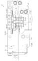
- FIG. 5 is a cross-sectional view taken along the line 6-6 of FIG. 5, which is an enlarged view of a main part of the focal length adjusting device.
- (A) to (c) are explanatory views showing the relationship between the position of the lens and the focal point. Explanatory drawing of the laser beam when the focal length is adjusted. Explanatory drawing of a laser beam when the focal length is not adjusted.
- the laser processing device 10 includes a laser oscillator 11, a focal length adjusting device 12, a scanning unit 13, an optical member 14, an input unit 15, and a control unit 16.
- the laser oscillator 11 emits a laser beam Lw that processes the work W.
- the laser oscillator 11 is a laser light source such as a YAG laser, a CO 2 laser, or a fiber laser.
- the laser beam Lw is applied to the work W via the focal length adjusting device 12, the scanning unit 13, and the optical member 14.
- the focal length adjusting device 12 has a function as a beam expander that adjusts (enlarges) the beam diameter of the laser beam Lw emitted from the laser oscillator 11. Further, the focal length adjusting device 12 has a function as a focal length adjusting device for adjusting the focal length of the laser beam.
- the scanning unit 13 scans the laser beam Lw emitted from the laser oscillator 11.
- the scanning unit 13 includes a pair of galvano mirrors 21 and 22 and motors 23 and 24 for driving the pair of galvano mirrors 21 and 22.
- Galvano mirrors 21 and 22 are, for example, total reflection mirrors.
- the galvano mirrors 21 and 22 are rotatably supported in a predetermined direction, respectively.
- the galvano mirror 21 is rotatably supported in a first direction (for example, the X-axis direction) with respect to the work W, and the galvano mirror 22 is orthogonal to the work W in a second direction (orthogonal to the first direction). It is supported so as to be rotatable in the Y-axis direction, for example.
- the motor 23 rotates and drives the galvano mirror 21, and the motor 24 rotates and drives the galvano mirror 22.
- the scanning unit 13 can two-dimensionally scan the laser beam Lw in two predetermined directions (X-axis direction and Y-axis direction) with respect to the work W.
- the laser beam Lw reflected by the scanning unit 13 is applied to the work W via the optical member 14.
- the optical member 14 is a member having translucency with respect to the laser beam Lw, and is, for example, a focusing (converging) lens, a glass member (protective glass), or the like.
- the optical member 14 is a focusing lens
- the optical member 14 has a configuration in which the laser beam Lw whose beam diameter is adjusted (or, in some cases, the focusing angle is also adjusted) is focused by the focal length adjusting device 12. It becomes.
- the optical member 14 is a glass member (protective glass)
- the optical member 14 is configured to transmit the laser beam Lw whose beam diameter and focusing angle are adjusted by the focal length adjusting device 12.
- the laser processing device 10 irradiates the work W with the laser beam Lw to process the work W.
- the processing by the laser beam Lw includes a process of removing (cutting) a part of the surface of the work W according to the processing pattern, a process of discoloring and deteriorating a part of the surface of the work W according to the processing pattern by the heat of the laser light Lw, and the like. include.
- the input unit 15 is composed of an input device such as a keyboard and a mouse, a display device such as a liquid crystal display, and a PC. By operating the input unit 15, the operator can set the intensity of the laser beam Lw, the scanning speed, the distance between workpieces, the processing pattern, and the like in the control unit 16.
- the input unit 15 may be provided with a touch panel. Further, the input unit 15 may be a mobile terminal, for example, and may be connected to the control unit 16 by wireless communication.
- the control unit 16 controls the laser oscillator 11, the focal length adjusting device 12, and the scanning unit 13 based on various settings. For example, the control unit 16 controls the intensity (laser power, output level) of the laser light Lw emitted from the laser oscillator 11 and the on / off of the laser light Lw based on the intensity setting. Further, the control unit 16 controls the motors 23 and 24 of the scanning unit 13 and controls the focal length adjusting device 12 based on the machining pattern. As a result, the laser beam Lw is irradiated to a desired position of the work W by rotating the galvanometer mirrors 21 and 22, and the focal length of the laser beam is adjusted.
- the focal length adjusting device 12 has at least two lenses 31 and 32.
- the first lens 31 is, for example, a concave lens
- the second lens 32 is, for example, a convex lens.
- the first lens 31 and the second lens 32 expand the beam diameter of the incident laser light and output the laser light Lw which becomes parallel light.
- the optical member 14 is a focusing (converging) lens
- the laser beam Lw which is parallel light, is focused.
- the laser beam Lw transmitted through the second lens 32 has a spread, that is, the beam diameter gradually increases.
- the focal position of the laser beam Lw focused by the optical member 14 due to the laser beam Lw is farther from the optical member 14 than the focal position shown in FIG. 7A. That is, the focal length of the laser beam Lw becomes long.
- the laser beam Lw transmitted through the second lens 32 is narrowed down, that is, the beam diameter is gradually reduced.
- the focal position of the laser beam Lw focused by the optical member 14 due to the laser beam Lw is closer to the optical member 14 than the focal position shown in FIG. 7A. That is, the focal length of the laser beam Lw becomes shorter.
- the focal length adjusting device 12 includes a base 40, a lens holder 51, a holder base 52, a guide portion 60, a holding portion 70, a stepping motor (hereinafter, simply referred to as “motor”) 80, and a conversion. It has a part 90.
- the base 40 is fixed to an optical base (not shown) to which the laser oscillator 11 and the scanning unit 13 shown in FIG. 1 are fixed.
- the base 40 has a base plate 41 fixed to the optical base and a fixing portion 42 erected from the base plate 41.
- the base plate 41 and the fixing portion 42 are integrally formed.
- the holder base 52 is fixed to the base plate 41, and the guide portion 60 and the motor 80 are fixed to the fixed portion 42.
- the holding portion 70 is fixed to the guide portion 60.
- the conversion unit 90 is interposed between the motor 80 and the holding unit 70.
- the holding unit 70 holds the first lens 31.
- the holding portion 70 has a base plate 71 and a lens fixing portion 72 provided on the side surface of the base plate 71.
- the lens fixing portion 72 is formed in a cylindrical shape, and the first lens 31 is inserted therein.
- a fixing ring 73 is attached to the lens fixing portion 72, and the first lens 31 is fixed by the fixing ring 73.
- the focal length adjusting device 12 is arranged so that the center of the first lens 31 is on the optical axis Lx of the laser beam Lw.
- the base plate 71 has a first base portion 71a and a second base portion 71b extending along the optical axis Lx of the laser beam Lw.
- the base plate 71 (first base portion 71a and second base portion 71b) is fixed to a guide portion 60 fixed to the base 40.
- the guide portion 60 has one rail 61 and a first block 62a and a second block 62b attached to the rail 61.
- the rail 61 is fixed to the base 40 so as to extend along the optical axis Lx of the laser beam Lw.
- the first block 62a and the second block 62b move along the rail 61, that is, the first block 62a and the second block 62b move along the optical axis Lx of the laser beam Lw.
- the base plate 71 of the holding portion 70 is fixed to the first block 62a and the second block 62b.
- the first base portion 71a of the base plate 71 is fixed to the first block 62a
- the second base portion 71b of the base plate 71 is fixed to the second block 62b. Therefore, the lens fixing portion 72 to which the first lens 31 is fixed is arranged between the first block 62a and the second block 62b.
- the motor 80 has a shaft body 81 that rotates under control.
- the motor 80 is fixed to the base 40 so that the central axis O1 of the shaft body 81 is orthogonal to the optical axis Lx of the laser beam Lw in a plan view.
- "planar view” means viewing from a direction perpendicular to the upper surface 41a of the base plate 41 of the base 40.
- the object is viewed from a direction orthogonal to the optical axis Lx of the laser beam Lw and parallel to the surface of the base 40 to which the rail 61 of the guide portion 60 is attached.
- the conversion unit 90 converts the rotational movement of the shaft body 81 of the motor 80 into the linear motion of the holding unit 70.
- the conversion unit 90 includes an arm unit 91 and a connecting unit 92.
- the arm portion 91 is fixed to the shaft body 81 of the motor 80.
- the arm portion 91 rotates integrally with the shaft body 81.
- the connecting portion 92 transmits a kinetic force between the arm portion 91 and the holding portion 70 from the converting portion 90 to the holding portion 70 in a direction parallel to the optical axis Lx of the laser beam Lw, and the shaft body 81. No kinetic force is transmitted in the direction parallel to the central axis O1 of.
- the connecting portion 92 has a support shaft 93, bearings 94a, 94b, 94c, and engaging pieces 95a, 95b, 95c.
- the arm portion 91 is formed so as to extend in the radial direction of the shaft body 81 of the motor 80, and is fixed to the shaft body 81 so as to rotate integrally with the shaft body 81.
- the support shaft 93 is fixed to the tip of the arm portion 91 and extends from the arm portion 91 in parallel with the central axis O1 of the shaft body 81 of the motor 80.
- the connecting portion 92 of the present embodiment has three bearings 94a, 94b, 94c.
- the three bearings 94a, 94b, 94c are attached to the support shaft 93.
- the three bearings 94a, 94b, 94c are arranged along the central axis of the support shaft 93, that is, along the direction parallel to the central axis O1 of the shaft body 81 of the motor 80.
- Each bearing 94a-94c has an inner ring, an outer ring, a ball or roller and a retainer for holding them.
- the inner ring of each bearing 94a to 94c is fixed to the support shaft 93.
- the outer ring of each bearing 94a to 94c rotates freely with respect to the inner ring, that is, the support shaft 93.
- the connecting portion 92 of the present embodiment has three engaging pieces 95a, 95b, 95c.
- the three engaging pieces 95a to 95c are fixed to the base plate 71 of the holding portion 70.
- the engaging pieces 95a to 95c are arranged along the direction parallel to the optical axis Lx of the laser beam Lw with respect to the bearings 94a to 94c.
- the engaging pieces 95a to 95c engage with the bearings 94a to 94c in the first direction parallel to the optical axis Lx of the laser beam Lw and in the second direction opposite (opposite) to the first direction. More specifically, at least one of the three engaging pieces 95a-95c engages the bearing in the first direction and the other engaging piece engages the bearing in the second direction.
- the central bearing 94b of the three bearings 94a to 94c attached to the support shaft 93 has the engaging piece 95b and the first direction (right direction in FIG. 6). Engage in. There is nothing that engages with this one bearing 94b in the second direction (to the left in FIG. 6). Then, the bearings 94a, 94c on both sides of the three bearings 94a to 94c engage with the engaging pieces 95a, 95c in the second direction (to the left in FIG. 6). As for these two bearings 94a and 94c, none of them engages in the first direction (right direction in FIG. 6).
- the distance between the engaging pieces 95b and the engaging pieces 95a and 95c in the direction parallel to the optical axis Lx is equal to the outer diameter dimension of the bearings 94a to 94c. That is, the engaging pieces 95b and the bearings 94b are in contact with each other, and the engaging pieces 95a and 95c and the bearings 94a and 94c are in contact with each other.
- the holder base 52 is fixed to the base plate 41 of the base 40.
- the lens holder 51 of the present embodiment holds the second lens 32 and the third lens 33.
- the lens holder 51 is attached to a holder base 52 fixed to the base 40.
- the holder base 52 is configured so that the angle of the lens holder 51, that is, the angle of the second lens 32 can be adjusted.
- the optical axes of the second lens 32 and the third lens 33 are adjusted to be the same as the optical axis Lx of the laser beam Lw.
- the optical member 14 shown in FIG. 1 can be a glass member (protective glass).
- the third lens 33 concentrates the laser beam Lw instead of the optical member 14.
- the optical member 14 is a focusing (converging) lens, one of the second lens 32 and the third lens 33 can be omitted.
- a photoelectric sensor 43 is attached to the base plate 41.
- the photoelectric sensor 43 is provided to move the first lens 31 held by the holding portion 70 to the initial position.
- a light-shielding plate 75 is fixed to the base plate 71 (first base portion 71a) of the holding portion 70.
- the control unit 16 drives the motor 80 until the photoelectric sensor 43 detects the light-shielding plate 75, and then drives the motor 80 in a predetermined pulse in the opposite direction to move the holding unit 70, that is, the first lens 31 to the initial position. Let me.
- control unit 16 moves the holding unit 70 at high speed until the photoelectric sensor 43 detects the light-shielding plate 75.
- the control unit 16 reverses the moving direction of the holding unit 70 and moves the holding unit 70 at a low speed until the photoelectric sensor 43 does not detect the light-shielding plate 75.
- the control unit 16 moves the holding unit 70 toward the photoelectric sensor 43 at a low speed until the photoelectric sensor 43 detects the light-shielding plate 75. In this way, by using the high-speed movement and the low-speed movement, the holding portion 70 can be moved to the initial position accurately in a short time.
- the focal length adjusting device 12 has a holding portion 70 for holding the first lens 31, a guide portion 60 for supporting the holding portion 70 so as to be movable along the optical axis Lx of the laser beam Lw, and a shaft body 81.
- a stepping motor 80 arranged so that the central axis O1 of the shaft body 81 is orthogonal to the optical axis Lx is interposed between the shaft body 81 and the holding portion 70, and the rotational motion of the shaft body 81 is transferred to the straight line of the holding portion 70.
- a conversion unit 90 that converts motion into motion is provided.
- the conversion unit 90 transmits kinetic force from the conversion unit 90 to the holding unit 70 in a direction parallel to the optical axis Lx and in a direction parallel to the central axis O1 of the shaft body 81.
- a connecting portion 92 that does not transmit kinetic force.
- the central axis O1 of the shaft body 81 of the stepping motor 80 is converted into the linear motion of the holding unit 70 by the conversion unit 90 that converts the rotational movement of the shaft body 81 of the stepping motor 80 into the linear motion of the holding unit 70.
- the focal distance adjusting device 12 can be miniaturized.
- the connecting portion 92 of the conversion unit 90 transmits the kinetic force in the direction parallel to the optical axis Lx, and does not transmit the kinetic force in the direction parallel to the central axis O1 of the shaft body 81.
- the connecting portion 92 includes an arm portion 91 extending from the shaft body 81 in the radial direction of the shaft body 81, a support shaft 93 extending from the arm portion 91 in parallel with the central axis O1 of the shaft body 81, and a bearing fixed to the support shaft 93. It includes 94a to 94c and engaging pieces 95a to 95c that engage with bearings 94a to 94c in a direction parallel to the optical axis Lx.
- the inner ring of the bearings 94a to 94c is fixed to the support shaft 93, and the outer ring of the bearings 94a to 94c engages with the engaging pieces 95a to 95c.
- the inner ring of the bearings 94a to 94c rotates relative to the outer ring that engages with the engaging pieces 95a to 95c, so that the resistance to the movement of the support shaft 93 is extremely small, and the holding portion 70, that is, the first The lens 31 can be easily moved.
- the central bearing 94b of the three bearings 94a to 94c is the first bearing, and the engaging piece 95b that engages with the first bearing 94b is the first engaging piece. Further, the bearings 94a and 94c on both sides of the first bearing 94b are used as the second bearing, and the engaging pieces 95a and 95c that engage with the second bearings 94a and 94c are used as the second engaging piece.
- the first bearing 94b engages with the first engaging piece 95b in the first direction parallel to the optical axis Lx. Therefore, when the engaging piece 95b is pressed by the first bearing 94b to move the holding portion 70 in the first direction, the holding portion 70 is moved on the line connecting the first bearing 94b and the first engaging piece 95b. Exercise power is generated.
- the second bearings 94a and 94c engage with the second engaging pieces 95a and 95c in the second direction opposite to the first direction. Therefore, when the two second engaging pieces 95a, 95c are pressed by the two second bearings 94a, 94c to move the holding portion 70 in the second direction, the space between the two second bearings 94a, 94c, that is, the first A kinetic force for moving the holding portion 70 is generated on the line connecting the 1 bearing 94b and the first engaging piece 95b.
- the focal length adjusting device 12 of the present embodiment faces the opposite directions at the same position when the holding portion 70 is moved in the first direction and when the holding portion 70 is moved in the second direction. Exercise power is generated. Therefore, the holding portion 70, that is, the first lens 31, can be easily moved without applying kinetic force in other directions.
- the first bearing 94b engages with the first engaging piece 95b in the first direction, and nothing engages in the second direction.
- the second bearings 94a, 94c engage with the second engaging pieces 95a, 95c in the second direction, and none engages in the first direction.
- the inner ring of each of the bearings 94a to 94c is rotatable with respect to the outer ring, the outer ring of the first bearing 94b and the outer ring of the second bearings 94a and 94c rotate in opposite directions to the motor 80.
- Each bearing 94a to 94c can be easily moved by the drive of. Therefore, the displacement of the holding portion 70 can be suppressed between when the holding portion 70 is moved in the first direction and when the holding portion 70 is moved in the second direction, and the holding portion 70, that is, the first lens can be accurately suppressed. 31 can be moved.
- the distance between the first engaging piece 95b and the second engaging pieces 95a, 95c is equal to the outer diameter dimension of each bearing 94a to 94c. Therefore, there is no play between the first bearing 94b and the first engaging piece 95b, and between the second bearings 94a and 94c and the second engaging piece 95a and 95c. Even in such a state, as described above, the outer ring of the first bearing 94b and the outer ring of the second bearings 94a and 94c rotate in opposite directions, so that the bearings 94a to 94c are engaged with each other. It can move without sliding with 95a to 95c. Therefore, the moving direction of the holding portion 70 can be reversed without moving the holding portion 70 from one direction for positioning or providing a means for urging, and the holding portion 70 can be easily moved. Can be positioned.
- FIG. 9 is an explanatory diagram of a comparative example with respect to the laser processing apparatus 10 of the present embodiment.
- FIG. 9 shows the relationship between the machined surface Wa of the work W and the laser beam Lw when the focal length D9 from the optical member 14 to the focal length Lp of the laser beam Lw is not adjusted.
- the laser beam Lw is irradiated perpendicularly to the processing surface Wa.
- the work W is arranged so that the focal point Lp of the laser beam Lw comes to the machined surface Wa.
- the laser beam Lw is obliquely irradiated to the processed surface Wa around the processing range. If the focal length D9 of the laser beam Lw is not adjusted, the focal length Lp of the laser beam Lw will move upward from the machined surface Wa.
- the machined surface Wa is irradiated with the laser light Lw spreading from the focal point Lp, and the area of the spot light formed on the machined surface Wa irradiated with the laser light Lw is the area of the machined surface Wa. It is larger than the area of the spot light formed by the vertically irradiated laser light Lw.
- the laser processing apparatus 10 of the present embodiment adjusts the focal length of the laser beam Lw.
- the focal length Lp of the laser beam Lw is set in a range in which the laser beam Lw is obliquely irradiated to the machined surface Wa of the work W, for example, in a peripheral region of the machining range on the machined surface Wa of the work W.
- the focal length D8a of the laser beam Lw is adjusted so that it is on the machined surface Wa.
- the area of the spot light generated by the irradiated laser light Lw can be reduced in the region where the laser light Lw is obliquely irradiated with respect to the machined surface Wa.
- the focal length D8b of the laser beam Lw is adjusted to make the focal length D8b shorter than the above-mentioned focal length D8a. That is, the focal lengths D8a and D8b of the laser beam Lw are adjusted according to the irradiation position of the machined surface Wa of the work W that irradiates the laser beam Lw.
- the laser machining apparatus 10 of the present embodiment defocuses the focus Lp of the laser beam Lw from the machined surface Wa in a region where the laser beam Lw is irradiated at an angle close to perpendicular to the machined surface Wa of the work W. Take control.
- the shape of the spot light on the machined surface Wa becomes elliptical.
- the shape of the spot light is circular in the region where the laser light Lw is irradiated perpendicularly to the machined surface Wa.
- the area of the spot light is smaller than the area of the spot light when the laser light Lw is obliquely irradiated with respect to the machined surface Wa. Therefore, if the focal point Lp of the laser beam Lw is shifted from the machined surface Wa, the area of the spot light can be increased. Thereby, the variation in the area of the spot light on the processed surface Wa can be reduced.
- the focal length adjusting device 12 includes a holding portion 70 that holds the first lens 31, a guide portion 60 that movably supports the holding portion 70 along the optical axis Lx of the laser beam Lw, and a shaft body 81.
- the stepping motor 80 which has a central axis O1 of the shaft body 81 and is arranged so as to be orthogonal to the optical axis Lx, is interposed between the shaft body 81 and the holding portion 70, and holds the rotational movement of the shaft body 81. It includes a conversion unit 90 that converts the linear motion of 70 into a linear motion.
- the conversion unit 90 transmits kinetic force from the conversion unit 90 to the holding unit 70 in a direction parallel to the optical axis Lx and in a direction parallel to the central axis O1 of the shaft body 81.
- a connecting portion 92 that does not transmit kinetic force.
- the central axis O1 of the shaft body 81 of the stepping motor 80 is converted into the linear motion of the holding unit 70 by the conversion unit 90 that converts the rotational movement of the shaft body 81 of the stepping motor 80 into the linear motion of the holding unit 70.
- the focal distance adjusting device 12 can be miniaturized.
- the connecting portion 92 of the conversion unit 90 transmits the kinetic force in the direction parallel to the optical axis Lx, and does not transmit the kinetic force in the direction parallel to the central axis O1 of the shaft body 81.
- the connecting portion 92 is fixed to the arm portion 91 extending from the shaft body 81 in the radial direction of the shaft body 81, the support shaft 93 extending from the arm portion 91 in parallel with the central axis O1 of the shaft body 81, and the support shaft 93.
- the bearings 94a to 94c are provided with engaging pieces 95a to 95c that engage with the bearings 94a to 94c in a direction parallel to the optical axis Lx.
- the inner ring of the bearings 94a to 94c is fixed to the support shaft 93, and the outer ring of the bearings 94a to 94c engages with the engaging pieces 95a to 95c.
- the inner ring of the bearings 94a to 94c rotates relative to the outer ring that engages with the engaging pieces 95a to 95c, so that the resistance to the movement of the support shaft 93 is extremely small, and the holding portion 70, that is, the first The lens 31 can be easily moved.
- the first bearing 94b engages with the first engaging piece 95b in the first direction parallel to the optical axis Lx. Therefore, when the first engaging piece 95b is pressed by the first bearing 94b to move the holding portion 70 in the first direction, the holding portion 70 is placed on the line connecting the first bearing 94b and the first engaging piece 95b. Motivation to move is generated.
- the second bearings 94a and 94c engage with the second engaging pieces 95a and 95c in the second direction opposite to the first direction.
- the focal length adjusting device 12 of the present embodiment has a kinetic force that goes in opposite directions at the same position when the holding portion 70 is moved in the first direction and when the holding portion 70 is moved in the second direction. Occurs. Therefore, the holding portion 70, that is, the first lens 31, can be easily moved without applying kinetic force in other directions.
- the first bearing 94b engages with the first engaging piece 95b in the first direction, and nothing engages in the second direction.
- the second bearings 94a, 94c engage with the second engaging pieces 95a, 95c in the second direction, and none engages in the first direction.
- the inner ring of each of the bearings 94a to 94c is rotatable with respect to the outer ring, the outer ring of the first bearing 94b and the outer ring of the second bearings 94a and 94c rotate in opposite directions to the motor 80.
- Each bearing 94a to 94c can be easily moved by the drive of. Therefore, the displacement of the holding portion 70 can be suppressed between when the holding portion 70 is moved in the first direction and when the holding portion 70 is moved in the second direction, and the holding portion 70, that is, the first lens can be accurately suppressed. 31 can be moved.
- the distance between the first engaging piece 95b and the second engaging pieces 95a, 95c in the direction parallel to the optical axis Lx is equal to the outer diameter dimension of each bearing 94a to 94c. Therefore, there is no play between the first bearing 94b and the first engaging piece 95b, and between the second bearings 94a and 94c and the second engaging piece 95a and 95c. Even in such a state, as described above, the outer ring of the first bearing 94b and the outer ring of the second bearings 94a and 94c rotate in opposite directions, so that the bearings 94a to 94c are engaged with each other. It can move without sliding with 95a to 95c. Therefore, the moving direction of the holding portion 70 can be reversed without moving the holding portion 70 from one direction for positioning or providing a means for urging, and the holding portion 70 can be easily moved. Can be positioned.
- the focal length Lp of the laser beam Lw is set on the machined surface Wa.
- the focal length D8a of the laser beam Lw is adjusted so as to be.
- the focal length D8b of the laser beam Lw is adjusted to make the focal length D8b shorter than the above-mentioned focal length D8a.
- the laser machining apparatus 10 of the present embodiment defocuses the focus Lp of the laser beam Lw from the machined surface Wa in a region where the laser beam Lw is irradiated at an angle close to perpendicular to the machined surface Wa of the work W. Take control. Thereby, the variation in the area of the spot light on the processed surface Wa can be reduced.
- the laser processing device may be a laser processing device in which the laser oscillator 11 to the scanning unit 13 are housed in one housing, and the laser oscillator 11 and the focal length adjusting device 12 and the scanning unit 13 are housed in separate housings. It may be a laser processing apparatus having a configuration for accommodating.
- the number of bearings and engaging pieces constituting the conversion unit may be two or four or more.
- the focal length may be adjusted so that the focal length Lp of the laser beam Lw matches the machined surface Wa.
- the focal length is adjusted by moving the first lens 31 as shown in FIGS. 7 (a) to 7 (c).
- the second lens 32 or the third lens 33 shown in FIG. 3 may be moved to adjust the focal length.
- two of the first lens 31 and the third lens 33 may be moved to adjust the focal length.
- either the second lens 32 or the third lens 33 may be omitted.
- At least one of the first lens 31 to the third lens 33 may be composed of a plurality of lenses.
Landscapes
- Physics & Mathematics (AREA)
- Optics & Photonics (AREA)
- Engineering & Computer Science (AREA)
- Plasma & Fusion (AREA)
- Mechanical Engineering (AREA)
- General Physics & Mathematics (AREA)
- Laser Beam Processing (AREA)
- Lens Barrels (AREA)
Priority Applications (4)
| Application Number | Priority Date | Filing Date | Title |
|---|---|---|---|
| CN202190000352.0U CN220259847U (zh) | 2020-03-31 | 2021-01-26 | 焦点距离调节装置以及激光加工装置 |
| EP21779025.2A EP4130834A4 (en) | 2020-03-31 | 2021-01-26 | FOCAL DISTANCE ADJUSTMENT DEVICE AND LASER TREATMENT DEVICE |
| KR1020227023198A KR102651772B1 (ko) | 2020-03-31 | 2021-01-26 | 초점 거리 조정 장치 및 레이저 가공 장치 |
| US17/791,453 US20230061666A1 (en) | 2020-03-31 | 2021-01-26 | Focal length adjusting device and laser processing device |
Applications Claiming Priority (2)
| Application Number | Priority Date | Filing Date | Title |
|---|---|---|---|
| JP2020064001A JP7426656B2 (ja) | 2020-03-31 | 2020-03-31 | 焦点距離調整装置及びレーザ加工装置 |
| JP2020-064001 | 2020-03-31 |
Publications (1)
| Publication Number | Publication Date |
|---|---|
| WO2021199621A1 true WO2021199621A1 (ja) | 2021-10-07 |
Family
ID=77929067
Family Applications (1)
| Application Number | Title | Priority Date | Filing Date |
|---|---|---|---|
| PCT/JP2021/002582 WO2021199621A1 (ja) | 2020-03-31 | 2021-01-26 | 焦点距離調整装置及びレーザ加工装置 |
Country Status (7)
| Country | Link |
|---|---|
| US (1) | US20230061666A1 (zh) |
| EP (1) | EP4130834A4 (zh) |
| JP (1) | JP7426656B2 (zh) |
| KR (1) | KR102651772B1 (zh) |
| CN (1) | CN220259847U (zh) |
| TW (1) | TWI759091B (zh) |
| WO (1) | WO2021199621A1 (zh) |
Families Citing this family (1)
| Publication number | Priority date | Publication date | Assignee | Title |
|---|---|---|---|---|
| CN114346433B (zh) * | 2022-01-14 | 2024-08-23 | 深圳市优控激光科技有限公司 | 激光焊接枪 |
Citations (4)
| Publication number | Priority date | Publication date | Assignee | Title |
|---|---|---|---|---|
| JPH0966357A (ja) | 1995-08-30 | 1997-03-11 | Daiki Alum Kogyosho:Kk | 浸漬ヒーターの取付構造 |
| JP2005238327A (ja) | 2003-10-30 | 2005-09-08 | Sunx Ltd | レーザマーキング装置 |
| WO2009004787A1 (ja) * | 2007-07-04 | 2009-01-08 | Panasonic Corporation | カメラ装置および駆動機構 |
| JP2009291811A (ja) | 2008-06-05 | 2009-12-17 | Cmet Inc | 焦点位置調整装置、及びレーザ加工装置 |
Family Cites Families (9)
| Publication number | Priority date | Publication date | Assignee | Title |
|---|---|---|---|---|
| JPH0966375A (ja) * | 1995-08-31 | 1997-03-11 | Sony Corp | レーザマーキング装置 |
| JP2005237327A (ja) * | 2004-02-27 | 2005-09-08 | Sanmei Electric Co Ltd | 植物栽培方法と植物栽培用容器 |
| JP4345030B2 (ja) * | 2007-06-12 | 2009-10-14 | ソニー株式会社 | 光ディスク装置及び集光位置補正方法 |
| JP5707079B2 (ja) * | 2010-09-30 | 2015-04-22 | パナソニック デバイスSunx株式会社 | レーザ加工装置 |
| FR2973118B1 (fr) * | 2011-03-24 | 2013-08-23 | Centre Nat Rech Scient | Dispositif numerique et adaptatif de focalisation d'un faisceau laser |
| KR101542680B1 (ko) * | 2013-01-03 | 2015-08-06 | 주식회사 나노포토닉스 | 삼차원 광학적 조향장치와 유한한 크기의 물체면을 가지는 대물 렌즈 및 그로부터 출력되는 발산광의 발산각과 빔 직경을 동시에 조절할 수 있는 z 스캐너 |
| WO2018008073A1 (ja) * | 2016-07-04 | 2018-01-11 | 三菱電機株式会社 | レーザ装置及びレーザ加工機 |
| CN107350227A (zh) * | 2017-09-05 | 2017-11-17 | 镇江金海创科技有限公司 | 焦距可调式激光清洗振镜 |
| JP2022135789A (ja) * | 2021-03-05 | 2022-09-15 | パナソニックIpマネジメント株式会社 | レーザ加工装置 |
-
2020
- 2020-03-31 JP JP2020064001A patent/JP7426656B2/ja active Active
-
2021
- 2021-01-26 CN CN202190000352.0U patent/CN220259847U/zh active Active
- 2021-01-26 EP EP21779025.2A patent/EP4130834A4/en active Pending
- 2021-01-26 US US17/791,453 patent/US20230061666A1/en active Pending
- 2021-01-26 WO PCT/JP2021/002582 patent/WO2021199621A1/ja active Application Filing
- 2021-01-26 KR KR1020227023198A patent/KR102651772B1/ko active IP Right Grant
- 2021-01-29 TW TW110103372A patent/TWI759091B/zh active
Patent Citations (4)
| Publication number | Priority date | Publication date | Assignee | Title |
|---|---|---|---|---|
| JPH0966357A (ja) | 1995-08-30 | 1997-03-11 | Daiki Alum Kogyosho:Kk | 浸漬ヒーターの取付構造 |
| JP2005238327A (ja) | 2003-10-30 | 2005-09-08 | Sunx Ltd | レーザマーキング装置 |
| WO2009004787A1 (ja) * | 2007-07-04 | 2009-01-08 | Panasonic Corporation | カメラ装置および駆動機構 |
| JP2009291811A (ja) | 2008-06-05 | 2009-12-17 | Cmet Inc | 焦点位置調整装置、及びレーザ加工装置 |
Non-Patent Citations (1)
| Title |
|---|
| See also references of EP4130834A4 |
Also Published As
| Publication number | Publication date |
|---|---|
| CN220259847U (zh) | 2023-12-29 |
| TWI759091B (zh) | 2022-03-21 |
| KR102651772B1 (ko) | 2024-03-28 |
| JP2021162715A (ja) | 2021-10-11 |
| TW202138094A (zh) | 2021-10-16 |
| EP4130834A4 (en) | 2023-11-01 |
| KR20220111320A (ko) | 2022-08-09 |
| JP7426656B2 (ja) | 2024-02-02 |
| US20230061666A1 (en) | 2023-03-02 |
| EP4130834A1 (en) | 2023-02-08 |
Similar Documents
| Publication | Publication Date | Title |
|---|---|---|
| JP4748728B2 (ja) | 回転レーザビームを生成する装置 | |
| JP4386137B2 (ja) | レーザ加工装置及びレーザ加工方法 | |
| KR101362738B1 (ko) | 레이저광에 의한 워크 가공 장치 | |
| GB2454365A (en) | An adjustable lens device using galvanometer motors to move the lens | |
| CN111872548A (zh) | 一种光束入射角可控的激光加工装置及激光加工方法 | |
| WO2021199621A1 (ja) | 焦点距離調整装置及びレーザ加工装置 | |
| JP3365388B2 (ja) | レーザ加工光学装置 | |
| CN213318327U (zh) | 一种光束入射角可控的激光加工装置 | |
| EP4302917A1 (en) | Laser processing device | |
| JP3003895B2 (ja) | レーザ加工装置 | |
| JP2021162715A5 (zh) | ||
| JP2002296533A (ja) | 光学偏向装置およびこれを用いたレーザ加工装置 | |
| WO2020050148A1 (ja) | レーザ光走査装置及びレーザ加工装置 | |
| JP5063402B2 (ja) | レーザ加工装置 | |
| JP2010264461A (ja) | レーザ加工方法、レーザ加工装置及びソーラパネル製造方法 | |
| JP3511049B2 (ja) | レ−ザ加工装置 | |
| JP4376221B2 (ja) | スキャン光学ユニット及びその制御方法並びにレーザ加工装置 | |
| JPS62197289A (ja) | レ−ザ加工装置 | |
| KR102001203B1 (ko) | 광학부재 마운트 장치 및 이를 포함하는 레이저 장치 | |
| JP2824170B2 (ja) | ロボット用レーザ加工装置 | |
| JPH0687089A (ja) | レーザ加工装置 | |
| KR20140112136A (ko) | 레이저 가공장치 | |
| JPH0691386A (ja) | レーザ加工装置 | |
| KR100765988B1 (ko) | 센터조정기능을 갖춘 표면가공장치 | |
| WO2019044294A1 (ja) | レーザー加工装置、レーザー加工システム |
Legal Events
| Date | Code | Title | Description |
|---|---|---|---|
| 121 | Ep: the epo has been informed by wipo that ep was designated in this application |
Ref document number: 21779025 Country of ref document: EP Kind code of ref document: A1 |
|
| ENP | Entry into the national phase |
Ref document number: 20227023198 Country of ref document: KR Kind code of ref document: A |
|
| WWE | Wipo information: entry into national phase |
Ref document number: 202190000352.0 Country of ref document: CN |
|
| NENP | Non-entry into the national phase |
Ref country code: DE |
|
| ENP | Entry into the national phase |
Ref document number: 2021779025 Country of ref document: EP Effective date: 20221031 |