WO2021192964A1 - 穿刺針及びカテーテル組立体 - Google Patents
穿刺針及びカテーテル組立体 Download PDFInfo
- Publication number
- WO2021192964A1 WO2021192964A1 PCT/JP2021/009034 JP2021009034W WO2021192964A1 WO 2021192964 A1 WO2021192964 A1 WO 2021192964A1 JP 2021009034 W JP2021009034 W JP 2021009034W WO 2021192964 A1 WO2021192964 A1 WO 2021192964A1
- Authority
- WO
- WIPO (PCT)
- Prior art keywords
- visual recognition
- puncture needle
- blood
- chamber
- state
- Prior art date
- Legal status (The legal status is an assumption and is not a legal conclusion. Google has not performed a legal analysis and makes no representation as to the accuracy of the status listed.)
- Ceased
Links
Images




Classifications
-
- A—HUMAN NECESSITIES
- A61—MEDICAL OR VETERINARY SCIENCE; HYGIENE
- A61M—DEVICES FOR INTRODUCING MEDIA INTO, OR ONTO, THE BODY; DEVICES FOR TRANSDUCING BODY MEDIA OR FOR TAKING MEDIA FROM THE BODY; DEVICES FOR PRODUCING OR ENDING SLEEP OR STUPOR
- A61M25/00—Catheters; Hollow probes
- A61M25/01—Introducing, guiding, advancing, emplacing or holding catheters
- A61M25/06—Body-piercing guide needles or the like
-
- A—HUMAN NECESSITIES
- A61—MEDICAL OR VETERINARY SCIENCE; HYGIENE
- A61M—DEVICES FOR INTRODUCING MEDIA INTO, OR ONTO, THE BODY; DEVICES FOR TRANSDUCING BODY MEDIA OR FOR TAKING MEDIA FROM THE BODY; DEVICES FOR PRODUCING OR ENDING SLEEP OR STUPOR
- A61M5/00—Devices for bringing media into the body in a subcutaneous, intra-vascular or intramuscular way; Accessories therefor, e.g. filling or cleaning devices, arm-rests
- A61M5/14—Infusion devices, e.g. infusing by gravity; Blood infusion; Accessories therefor
- A61M5/158—Needles for infusions; Accessories therefor, e.g. for inserting infusion needles, or for holding them on the body
Definitions
- the present invention relates to a puncture needle and a catheter assembly.
- a puncture needle such as an indwelling needle includes a hollow needle body for puncturing a blood vessel and a needle hub provided at the base end of the needle body.
- the needle hub has a blood introduction portion in which a chamber (flashback chamber) into which blood is introduced through the lumen of the needle body is formed when a blood vessel of the needle body is secured (see, for example, Japanese Patent Application Laid-Open No. 2009-233007). ).
- the user can know the blood vessel securing of the needle body by visually recognizing the blood inflow (blood flow) into the chamber.
- the puncture needle As described above, if the chamber is filled with blood before confirming the inflow of blood into the chamber, the user cannot confirm the subsequent securing of blood vessels in the needle body.
- a puncture needle is punctured into a blood vessel with high blood pressure (for example, an artery)
- blood flow confirmation time the time from the start of blood inflow in the chamber to the filling of the chamber with blood
- the blood introduction part needle hub
- the blood introduction part becomes large, which may deteriorate the operability of the puncture needle or increase the amount of the puncture needle discarded. There is.
- the present invention has been made in consideration of such a problem, and a puncture needle and a catheter assembly capable of miniaturizing the blood introduction portion and continuously confirming the securing of blood vessels in the needle body.
- the purpose is to provide a solid.
- One aspect of the present invention is a puncture needle provided with a hollow needle body for puncturing a blood vessel and a needle hub provided at a base end portion of the needle body, wherein the needle hub is the needle body.
- a blood introduction portion in which a chamber for introducing blood through the lumen of the needle body is formed at the time of securing a blood vessel, and a visibility portion provided in the blood introduction portion that can be visually recognized by a user are provided.
- the portion is a puncture needle that changes its appearance from the first state to the second state due to an increase in pressure in the chamber and returns from the second state to the first state due to a decrease in pressure in the chamber.
- Another aspect of the present invention comprises a catheter assembly comprising the puncture needle described above, a catheter shaft having a lumen through which the needle body is inserted, and a catheter hub provided at a proximal end of the catheter shaft. Is.
- the pressure in the chamber rises, so that the appearance of the visual recognition part changes from the first state to the second state.
- the user can know the securing of the blood vessel of the needle body by visually recognizing the second state of the visual recognition unit.
- the needle body in the blood vessel secured state becomes the blood vessel unsecured state, blood pressure does not act on the blood in the lumen of the needle body, so that the pressure in the chamber decreases and the appearance of the visual recognition part changes from the second state to the second state. Return to 1 state. In this case, the user can know that the blood vessel of the needle body is not secured by visually recognizing the first state of the visual recognition unit.
- the appearance of the visible portion reversibly changes between the first state and the second state according to the pressure in the chamber.
- the blood introduction portion can be miniaturized.
- FIG. 4A is a cross-sectional explanatory view in which the visible portion of FIG. 3 is in the second state
- FIG. 4B is a cross-sectional explanatory view in which the visible portion of FIG. 3 is in the first state.
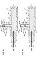
- FIG. 6A is a cross-sectional explanatory view in which the visible portion of FIG. 5 is in the second state
- FIG. 6B is a cross-sectional explanatory view in which the visible portion of FIG. 5 is in the second state
- 6B is a cross-sectional explanatory view in which the visible portion of FIG. 5 is in the first state. It is a partially omitted vertical sectional view of the puncture needle provided with the visual recognition part which concerns on the 2nd modification.
- 8A is a cross-sectional explanatory view in which the visible portion of FIG. 7 is in the second state, and FIG. 8B is a cross-sectional explanatory view in which the visible portion of FIG. 7 is in the first state. It is a partially omitted vertical sectional view of the puncture needle provided with the visual recognition part which concerns on the 3rd modification.
- 10A is a cross-sectional explanatory view in which the visible portion of FIG. 9 is in the second state, and FIG. 10B is a cross-sectional explanatory view in which the visible portion of FIG. 9 is in the first state.
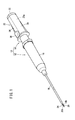
- the catheter assembly 10 is configured as an indwelling needle for administering an infusion solution (drug solution) into a blood vessel of a patient (living body).
- the catheter assembly 10 has a catheter member 12 and a puncture needle 14.
- the catheter member 12 has a catheter shaft 16 and a catheter hub 18 provided at a proximal end of the catheter shaft 16.
- the catheter shaft 16 is a tubular member that is flexible and can be continuously inserted into a patient's blood vessel.
- the catheter shaft 16 has a lumen 16a extending along the axial direction over its entire length.
- a tip opening 16b communicating with the lumen 16a is formed at the tip of the catheter shaft 16.
- the constituent material of the catheter shaft 16 is not particularly limited, but a transparent resin material, particularly a soft resin material is preferable, and for example, polytetrafluoroethylene (PTFE) and ethylene / tetrafluoroethylene co-weight.
- Fluororesin such as coalescence (ETFE), perfluoroalkoxy alkane resin (PFA), olefin resin such as polyethylene and polypropylene or a mixture thereof, polyurethane, polyester, polyamide, polyether nylon resin, olefin resin and ethylene-vinyl acetate Examples thereof include a mixture with a copolymer.
- the catheter hub 18 is formed in a hollow shape (cylindrical shape). Although not shown, the lumen 18a of the catheter hub 18 is provided with a hemostatic valve, a sealing member, and a plug. The catheter hub 18 has transparency so that the blood flowing into the lumen 18a of the catheter hub 18 can be visually recognized from the outside of the catheter hub 18.
- the catheter hub 18 is preferably made of a material harder than the catheter shaft 16.
- the constituent material of the catheter hub 18 is not particularly limited, but is thermoplastic, for example, polypropylene, polycarbonate, polyamide, polysulphon, polyarylate, methacrylate-butylene-styrene copolymer, polyurethane, acrylic resin, ABS resin and the like.
- a resin can be preferably used.
- the puncture needle 14 includes a needle body 20 and a needle hub 22 provided at the base end portion of the needle body 20.
- the needle body 20 is a tubular member having rigidity capable of puncturing the patient's skin.
- the needle body 20 has a lumen 20a extending along the axial direction. The needle body 20 is inserted into the lumen 16a of the catheter shaft 16 and the lumen 18a of the catheter hub 18 in the initial state (assembled state) of the catheter assembly 10 (see FIG. 1).
- the constituent material of the needle body 20 examples include metal materials such as stainless steel, aluminum, aluminum alloy, titanium, and titanium alloy.
- the needle body 20 is formed sufficiently longer than the catheter shaft 16 and protrudes from the tip opening 16b of the catheter shaft 16 in the initial state of the catheter assembly 10 (see FIG. 1).
- a blade surface 24 inclined with respect to the axis of the needle body 20 is formed at the tip end portion of the needle body 20.
- the blade surface 24 is formed with a tip opening 20b communicating with the lumen 20a of the needle body 20.
- the needle hub 22 is formed in a hollow shape (cylindrical shape).
- the constituent material of the needle hub 22 include the same constituent materials as those of the catheter hub 18 described above.
- the total length of the needle hub 22 is preferably set to 3 cm or more and 7 cm or less, and more preferably 4 cm or more and 5 cm or less.
- the needle hub 22 is provided on the needle body support portion 26 forming the tip portion thereof, the blood introduction portion 28 extending from the needle body support portion 26 to the proximal end side, and the blood introduction portion 28 so as to be visible to the user. It has a visual recognition unit 30.
- the base end portion of the needle body 20 is fixed to the needle body support portion 26.
- the blood introduction portion 28 is formed opaquely so that the inside cannot be visually recognized from the outside. However, the blood introduction unit 28 may have transparency.
- the blood introduction portion 28 is formed with a chamber 28a in which blood is introduced through the lumen 20a of the needle body 20 when the blood vessel of the needle body 20 is secured.
- the base end opening of the blood introduction portion 28 is liquid-tightly and airtightly sealed by the sealing member 32.
- the blood introduction unit 28 also functions as an operation unit when operating the puncture needle 14 or the catheter assembly 10.
- the visual recognition portion 30 is provided on the side wall portion 34 located above the wall portion of the blood introduction portion 28 when the blade surface 24 is turned upward (see FIGS. 1 and 2).
- the side wall portion 34 and the blade surface 24 have the same positions in the circumferential direction of the needle body 20.
- the visual recognition unit 30 has a visual recognition marker 36 and a storage portion 38 that movably accommodates the visual recognition marker 36.
- the visual recognition marker 36 is a colored liquid 40 colored in a color different from blood (a color other than red). Details of the coloring liquid 40 will be described later.
- the accommodating unit 38 includes a first accommodating unit 42 provided in the chamber 28a and a second accommodating unit 44 provided outside the blood introduction unit 28.
- the first accommodating portion 42 has a first tubular portion 46 extending along the axial direction of the needle body 20 and a second tubular portion extending from the first tubular portion 46 and fixed to the side wall portion 34 of the blood introduction portion 28. It has a part 48 and.
- the second tubular portion 48 is connected to one end of the first tubular portion 46 (the end on the needle body support portion 26 side).
- the first lumen 46a of the first tubular portion 46 is set to a size that can accommodate the entire coloring liquid 40.
- the other end of the first tubular portion 46 (the end on the sealing member 32 side) allows air to communicate between the inside of the chamber 28a and the first lumen 46a, while allowing air to pass from the chamber 28a to the first lumen.
- a filter unit 50 is provided to prevent the inflow of blood into 46a.
- a hydrophobic filter can be used as the filter unit 50.
- the filter portion 50 is liquid-tightly and airtightly fixed to the other end of the first tubular portion 46.
- the second tubular portion 48 extends from one end of the first tubular portion 46 in a direction intersecting the extending direction of the first tubular portion 46 (for example, in a direction orthogonal to each other).
- the second tubular portion 48 is inserted into a through hole 52 formed in the side wall portion 34 of the blood introduction portion 28.
- the outer peripheral surface of the second tubular portion 48 is liquid-tightly and airtightly fixed to the inner peripheral surface of the through hole 52.
- the second lumen 48a of the second tubular portion 48 communicates with each other between the first lumen 46a and the lumen 44a of the second accommodating portion 44.
- the lumen 44a of the second accommodating portion 44 is set to a size that can accommodate the entire colored liquid 40. Specifically, the volume of the lumen 44a of the second accommodating portion 44 is substantially the same as the volume of the first lumen 46a.
- the second accommodating portion 44 has transparency so that the inside can be visually recognized from the outside.
- the second accommodating portion 44 includes a peripheral wall portion 54 projecting outward from the outer surface of the side wall portion 34 of the blood introduction portion 28, and a top wall portion 56 provided at the protruding end portion of the peripheral wall portion 54.
- An air flow section 60 is provided in the opening 58 formed in the peripheral wall portion 54.
- the air flow unit 60 allows the flow of air between the lumen 44a of the second accommodating unit 44 and the outer space of the needle hub 22, while the colored liquid from the lumen 44a of the second accommodating unit 44 to the outer space. Block the distribution of 40.
- a hydrophobic filter can be used as the air flow unit 60.
- the air flow section 60 is liquid-tightly and airtightly fixed to the inner surface of the opening 58.
- the air flow unit 60 may be provided on the top wall portion 56 instead of the peripheral wall portion 54.
- the visual recognition marker 36 can be reversibly moved to the first lumen 46a (first position) of the first tubular portion 46 and the lumen 44a (second position) of the second accommodating portion 44.
- the visual marker 36 moves from the first position to the second position due to the pressure increase in the chamber 28a (see FIG. 4A). Further, when the pressure in the chamber 28a decreases, the visual recognition marker 36 returns from the second position to the first position due to the weight of the visual recognition marker 36 and the atmospheric pressure (see FIG. 4B).
- the column pressure of the colored liquid 40 is smaller than the blood pressure. This allows the colored liquid 40 to move from the first position to the second position (due to blood pressure) due to the influx of blood into the chamber 28a.
- a liquid having a relatively large specific density such as mercury or tetrabromoethane can be used. In this case, the colored liquid 40 tends to return from the second position to the first position due to its own weight.
- a liquid having a relatively small specific density such as an aqueous solution of glycerin can be used. In this case, the visual recognition marker 36 can easily move from the first position to the second position due to the pressure increase in the chamber 28a.
- FIG. 4A and FIG. 4B the illustration of the catheter member 12 is omitted. The same applies to FIGS. 6A, 6B, 8A, 8B, 10A and 10B, which will be described later.
- the blade surface 24 protrudes in the distal direction from the distal opening 16b of the catheter shaft 16 in a state of facing upward.
- the visual recognition marker 36 is located in the first lumen 46a (first position) of the first tubular portion 46 (see FIG. 3). That is, the user cannot visually recognize the visual recognition marker 36 in the lumen 44a of the second accommodating portion 44 (or it is difficult to visually recognize the visual recognition marker 36). That is, the visual recognition unit 30 is in the first state indicating that the blood vessel of the needle body 20 is not secured.
- the flow path cross-sectional area of the first tubular portion 46 is sufficiently small, and is equal to or less than the cross-sectional area of the filter portion 50. Therefore, the air in the chamber 28a can effectively press the visual recognition marker 36.
- the visual marker 36 pushed by the air moves to the lumen 44a (second position) of the second accommodating portion 44 via the second lumen 48a of the second tubular portion 48.
- the air existing in the second lumen 48a and the lumen 44a of the second accommodating portion 44 is discharged to the outer space of the needle hub 22 via the air flow portion 60.
- the appearance of the visual recognition unit 30 changes from the first state indicating that the blood vessel is not secured in the needle body 20 to the second state indicating that the blood vessel is secured.
- the user knows that the needle body 20 is in the blood vessel securing state by visually recognizing the second state of the visual recognition unit 30 (the state in which the visual recognition marker 36 is located in the lumen 44a of the second storage unit 44). Can be done.
- the needle body 20 which has been in the blood vessel secured state becomes the blood vessel unsecured state (for example, the tip opening 20b of the needle body 20 is located at a position outside the blood vessel), the blood in the lumen 20a of the needle body 20 Blood pressure does not work. Therefore, the blood existing in the lumen 20a of the needle body 20 is pushed out of the needle body 20 by the atmospheric pressure and the weight of the visual recognition marker 36.
- the visual recognition marker 36 in the lumen 44a (second position) of the second accommodating portion 44 has the atmospheric pressure and its own weight of the visual recognition marker 36. It is returned to the first lumen 46a (first position) of the first tubular portion 46 via the second lumen 48a of the second tubular portion 48.
- the user visually recognizes the first state of the visual recognition unit 30 (the state in which the visual recognition marker 36 is no longer located in the lumen 44a of the second accommodating portion 44), so that the needle body 20 is in a blood vessel unsecured state. You can know that.
- the visual recognition unit 30 In the state of FIG. 4B, when the blood vessel of the needle body 20 is secured again, the visual recognition unit 30 is in the state of FIG. 4A. That is, the appearance of the visual recognition unit 30 changes from the first state to the second state. Therefore, the user can continuously confirm the securing of the blood vessel of the needle body 20.
- the puncture needle 14 and the catheter assembly 10 according to the present embodiment have the following effects.
- the needle hub 22 is provided in the blood introduction portion 28 and the blood introduction portion 28 in which the chamber 28a in which the blood is introduced through the lumen 20a of the needle body 20 is formed when the blood vessel of the needle body 20 is secured.
- a visual recognition unit 30 that is visible to the user is provided. The appearance of the visual recognition unit 30 changes from the first state to the second state due to the increase in pressure in the chamber 28a, and returns from the second state to the first state due to the decrease in pressure in the chamber 28a.
- the pressure in the chamber 28a rises, so that the appearance of the visual recognition unit 30 changes from the first state to the second state. do.
- the user can know that the blood vessel of the needle body 20 is secured by visually recognizing the second state of the visual recognition unit 30.
- the needle body 20 in the blood vessel secured state becomes the blood vessel unsecured state
- blood pressure does not act on the lumen 20a of the needle body 20, so that the pressure in the chamber 28a decreases and the appearance of the visual recognition portion 30 becomes second.
- the user can know that the needle body 20 has not secured a blood vessel by visually recognizing the first state of the visual recognition unit 30.
- the appearance of the visual recognition unit 30 reversibly changes between the first state and the second state according to the pressure in the chamber 28a.
- the blood introduction unit 28 can be miniaturized.
- the visual recognition unit 30 has a visual recognition marker 36 and an accommodating portion 38 accommodating the visual recognition marker 36.
- the visual recognition marker 36 can be reversibly moved to a first position in which the visual recognition unit 30 is in the first state and a second position in which the visual recognition unit 30 is in the second state due to a change in pressure in the chamber 28a.
- the accommodating portion 38 is formed so that the visual recognition marker 36 at the second position can be visually recognized from the outside.
- the appearance of the visual recognition unit 30 can be effectively changed by moving the visual recognition marker 36 to the first position and the second position.
- the visual recognition unit 30 includes a filter unit 50 that allows the flow of air between the accommodating unit 38 and the chamber 28a while blocking the inflow of blood from the chamber 28a into the accommodating unit 38.
- the pressure of the air in the chamber 28a can be directly acted on the visual recognition marker 36 via the filter unit 50 to move the visual recognition marker 36 from the first position to the second position. Further, the filter unit 50 can prevent the blood that has flowed into the chamber 28a from flowing into the accommodating unit 38.
- the visual recognition unit 30 has an air flow unit 60 provided in the accommodating unit 38.
- the air flow unit 60 discharges the air in the accommodating unit 38 to the outer space of the needle hub 22 when the visual recognition marker 36 moves from the first position to the second position.
- the visual recognition marker 36 can be smoothly moved from the first position to the second position.
- the visual recognition marker 36 is a colored liquid 40.
- the visual recognition marker 36 can be deformed according to the shape of the accommodating portion 38, so that the degree of freedom in designing the accommodating portion 38 is improved.
- the visual recognition unit 30 does not have to have the air flow unit 60.
- the visual recognition marker 36 moves from the first position to the second position while compressing the air in the lumen 44a of the second accommodating portion 44 when securing the blood vessel of the needle body 20. Further, the visual recognition marker 36 moves from the second position to the first position due to the pressure of the compressed air in the lumen 44a of the second accommodating portion 44 and the weight of the visual recognition marker 36 when the blood vessel of the needle body 20 is not secured. do.
- the visual recognition unit 30a according to the first modification includes a housing unit 70, a visual recognition marker 72, an air flow unit 74, an elastic body 76, and a filter unit 78.
- the accommodating portion 70 is formed in a cylindrical shape.
- the accommodating portion 70 is provided in a recess 82 formed on the outer surface of the side wall portion 34 of the blood introduction portion 28.
- the accommodating portion 70 is inserted into the recess 82 so that a part of the accommodating portion 70 projects outward from the recess 82.
- At least a portion of the accommodating portion 70 protruding from the recess 82 has transparency so that the inside can be visually recognized from the outside.
- the accommodating portion 70 is liquid-tightly and airtightly fixed to the wall surface forming the recess 82.
- the accommodating portion 70 may be integrally molded with the blood introduction portion 28.
- the visual recognition marker 72 is a piston (solid) arranged in the lumen 70a of the accommodating portion 70 in a state of being movable in the axial direction of the accommodating portion 70.
- the visual recognition marker 72 divides the lumen 70a of the accommodating portion 70 into a first space 84 on one end side and a second space 86 on the other end side of the accommodating portion 70 (see FIG. 6A).
- the visual recognition marker 72 slides on the inner peripheral surface of the accommodating portion 70.
- the visual recognition marker 72 comes into liquid-tight and airtight contact with the inner peripheral surface of the accommodating portion 70.
- the visual marker 72 can be reversibly moved to the first position on one end side (blood introduction portion 28 side) of the accommodating portion 70 and the second position on the other end side (air flow portion 74 side) of the accommodating portion 70. ..
- the visual marker 72 is located in the recess 82 of the blood introduction portion 28 at the first position. Therefore, it is difficult for the user to see the visual recognition marker 72 at the first position from the outside of the needle hub 22.
- the visual recognition marker 72 is located outside the recess 82 at the second position. Therefore, the user can easily see the visual recognition marker 72 at the second position from the outside of the needle hub 22.
- the air flow unit 74 forms the other end (protruding end) of the accommodating unit 70.
- the air circulation unit 74 allows the flow of air between the second space 86 and the outer space of the needle hub 22, while blocking the flow of blood.
- a hydrophobic filter can be used as the air flow unit 74.
- the elastic body 76 is arranged in the second space 86 of the accommodating portion 70. In other words, the elastic body 76 is interposed between the visual recognition marker 72 and the air flow unit 74. The elastic body 76 urges the visual recognition marker 72 to one end side (blood introduction portion 28 side) of the accommodating portion 70.
- the elastic body 76 is a spring member. However, the elastic body 76 may be a rubber member that can be elastically deformed.
- the elastic body 76 functions as a return means 77 for returning the visual recognition marker 72 from the second position to the first position.
- the filter portion 78 is formed in the side wall portion 34 of the blood introduction portion 28, and is arranged in a through hole 88 that communicates the chamber 28a and the lumen 70a (first space 84) of the storage portion 70 with each other.
- the filter unit 78 allows air to communicate between the chamber 28a and the first space 84 of the containment unit 70, while blocking the inflow of blood from the chamber 28a into the first space 84 of the containment unit 70.
- a hydrophobic filter can be used as the filter unit 78.
- the filter portion 78 is liquid-tightly and airtightly fixed to the inner surface of the through hole 88.
- the visual recognition marker 72 is in the first position on one end side of the accommodation unit 70 in the initial state of the catheter assembly 10 (see FIG. 5).
- the visual recognition marker 72 is pushed by the air in the chamber 28a and the accommodating portion 70 It moves from the first position on one end side to the second position on the other end side.
- the elastic body 76 is pushed by the visual recognition marker 72 and elastically deformed (compressively deformed).
- the air between the visual recognition marker 72 and the air flow section 74 is pushed by the visual recognition marker 72 and discharged to the outer space via the air flow section 74.
- the visual recognition unit 30a has a first state (a state in which the visual recognition marker 72 is in the first position) indicating that the blood vessel of the needle body 20 is not secured, and a second state (the visual recognition marker 72 is the second state) indicating that the blood vessel of the needle body 20 is secured.
- the appearance changes to the state of being in the position).
- the user can know that the blood vessel of the needle body 20 is secured by visually recognizing the second state of the visual recognition unit 30a.
- the pressure in the chamber 28a decreases. Then, as shown in FIG. 6B, the visual recognition marker 72 at the second position is returned to the first position by the own weight of the visual recognition marker 72, the elastic force (restoring force) of the elastic body 76, and the atmospheric pressure. As a result, the user can know that the needle body 20 is in the blood vessel unsecured state by visually recognizing the first state of the visual recognition unit 30a.
- the visual recognition unit 30a In the state of FIG. 6B, when the blood vessel of the needle body 20 is secured again, the visual recognition unit 30a is in the state of FIG. 6A. That is, the appearance of the visual recognition unit 30a changes from the first state to the second state. Therefore, the user can continuously confirm the securing of the blood vessel of the needle body 20.
- the visual recognition unit 30a has a return means 77 for returning the visual recognition marker 72 from the second position to the first position.
- the visual marker 72 can be easily returned from the second position to the first position by the return means 77.
- the visual recognition marker 72 is a solid, and the return means 77 has an elastic body 76 provided in the accommodating portion 70 and elastically deformed by moving the visual recognition marker 72 from the first position to the second position.
- the visual recognition marker 72 can be easily returned from the second position to the first position by the restoring force of the elastic body 76.
- the visual recognition unit 30a does not have to have the air circulation unit 74.
- the protruding end of the accommodating portion 70 is formed by a wall portion that does not allow air and blood to flow. Then, the visual recognition marker 72 moves from the first position to the second position while compressing the air in the second space 86 of the accommodating portion 70. Further, the visual recognition marker 72 moves from the second position to the first position by the pressure of the compressed air in the second space 86 and the restoring force of the elastic body 76.
- the air and the elastic body 76 in the second space 86 of the accommodating portion 70 function as a returning means 77 for returning the visual recognition marker 72 from the second position to the first position.
- the visual recognition unit 30b according to the second modification includes a cylindrical portion 90, a visual recognition marker 92, a filter portion 94, a suspension portion 96, and an air flow portion 98.
- the tubular portion 90 is provided on the side wall portion 34 so as to project outward from the side wall portion 34 of the blood introduction portion 28. Specifically, the tubular portion 90 is inserted into the through hole 100 formed in the side wall portion 34 of the blood introduction portion 28. At least a portion of the tubular portion 90 protruding from the through hole 100 has transparency so that the inside can be visually recognized from the outside. The portion of the tubular portion 90 inserted into the through hole 100 is in liquid-tight and airtight contact with the inner peripheral surface of the through hole 100.
- the tubular portion 90 may be integrally molded with the blood introduction portion 28.
- the visual recognition marker 92 has a marker main body 92a arranged in the lumen 90a of the tubular portion 90 in a state of being movable in the axial direction of the tubular portion 90, and a weight portion 92b provided in the marker main body 92a.
- the marker main body 92a slides on the inner peripheral surface of the tubular portion 90.
- the marker main body 92a is in liquid-tight and airtight contact with the inner peripheral surface of the tubular portion 90.
- the marker main body 92a partitions the lumen 90a of the tubular portion 90 into a first space 102 on one end side of the tubular portion 90 and a second space 104 on the other end side of the tubular portion 90.
- the first space 102 of the tubular portion 90 communicates with the chamber 28a.
- the weight portion 92b is fixed to the surface of the visual recognition marker 92 opposite to the blood introduction portion 28.
- the specific density of the visual marker 92 (the specific gravity of the marker body 92a and the weight portion 92b combined) is lighter than the specific density of blood. That is, the visual recognition marker 92 is formed so as to float with respect to blood.
- the visual recognition marker 92 has a first position in which the visual recognition portion 30b is in the first state and a visual recognition portion 30b in the second state due to a change in pressure in the chamber 28a (due to a change in the liquid level of blood in the tubular portion 90). It is reversibly movable to the second position.
- the filter unit 94 is provided on the marker main body 92a.
- the filter unit 94 allows the flow of air between the first space 102 and the second space 104 of the tubular portion 90, while blocking the flow of blood from the first space 102 to the second space 104.
- a hydrophobic filter can be used as the filter unit 94.
- the hanging portion 96 is provided at the protruding end portion (air flow portion 98) of the tubular portion 90, and is for suspending the visual recognition marker 92 at the first position in a state where the blood vessel of the needle body 20 is not secured.
- the hanging portion 96 is an elastic body 106 that elastically deforms when the visual recognition marker 92 moves from the first position to the second position.
- the elastic body 106 for example, a spring, rubber, or the like is used.
- the hanging portion 96 is not limited to the elastic body 106, and may be, for example, a thread.
- the length of the hanging portion 96 is set so as to be located in the middle of the tubular portion 90 in the axial direction in a state where blood is not in contact with the visual recognition marker 92.
- the length of the hanging portion 96 can be set as appropriate.
- the air flow unit 98 forms a protruding end portion of the tubular portion 90.
- the air circulation unit 98 allows the flow of air between the second space 104 of the tubular portion 90 and the outer space of the needle hub 22, while preventing the outflow of blood from the second space 104 to the outer space.
- a hydrophobic filter can be used as the air flow unit 98.
- the filter section 94 and the air flow section 98 form an air release section 108 for letting the air in the chamber 28a escape to the outside.
- the visual recognition marker 92 is at the first position in the middle of the tubular portion 90 in the axial direction (see FIG. 7). Further, blood does not exist in the first space 102 of the tubular portion 90.
- the air in the chamber 28a flows from the first space 102 of the tubular portion 90 to the filter portion 94, the second space 104 and the air flow. It is discharged to the outer space through the portion 98. Then, after filling the chamber 28a, the blood flows into the first space 102 of the tubular portion 90 and comes into contact with the marker main body 92a.
- the marker main body 92a is pushed upward by the blood and moves from the first position to the second position on the other end side of the tubular portion 90.
- the air in the second space 104 of the tubular portion 90 is discharged to the outside via the air flow portion 98, and the hanging portion 96 is elastically deformed.
- the visual recognition unit 30b indicates that the blood vessel of the needle body 20 is secured from the first state (a state in which the visual recognition marker 92 is in the first position and blood does not exist in the first space 102) indicating that the blood vessel of the needle body 20 is not secured.
- the appearance changes to the second state (a state in which the visual recognition marker 92 is in the second position and blood is present in the first space 102). Therefore, the user can know that the blood vessel of the needle body 20 is secured by visually recognizing the second state of the visual recognition unit 30b.
- the needle body 20 in the blood vessel secured state becomes the blood vessel unsecured state
- the blood in the chamber 28a fills the lumen 20a of the needle body 20 due to the column pressure and the atmospheric pressure of the blood in the tubular portion 90. Since it is pushed out through the chamber 28a, the pressure in the chamber 28a is reduced.
- the visual recognition marker 92 is determined by the own weight of the visual recognition marker 92 (the own weight of the marker main body 92a and the own weight of the weight portion 92b), the restoring force of the elastic body 106 (suspended portion 96), and the atmospheric pressure. Move from the 2nd position to the 1st position. At this time, the visual recognition marker 92 is stopped at the first position by the hanging portion 96. Therefore, the user can know that the needle body 20 is in the blood vessel unsecured state by visually recognizing the first state of the visual recognition unit 30b.
- the visual recognition unit 30b In the state of FIG. 8B, when the blood vessel of the needle body 20 is secured again, the visual recognition unit 30b is in the state of FIG. 8A. That is, the appearance of the visual recognition unit 30b changes from the first state to the second state. Therefore, the user can continuously confirm the securing of the blood vessel of the needle body 20.
- the visual recognition portion 30b has a tubular portion 90 provided in the blood introduction portion 28 so as to project outward from the blood introduction portion 28. At least a portion of the tubular portion 90 protruding from the blood introduction portion 28 is formed so that the inside can be visually recognized from the outside.
- the lumen 90a (first space 102) of the tubular portion 90 communicates with the chamber 28a.
- the visual recognition unit 30b is provided with an air release unit 108 for releasing the air in the chamber 28a to the outside.
- blood can flow into the lumen 90a (first space 102) of the tubular portion 90 when the blood vessel of the needle body 20 is secured. Further, when the blood vessel of the needle body 20 is not secured, blood can be discharged from the lumen 90a (first space 102) of the tubular portion 90 to the chamber 28a side. Therefore, the appearance of the visual recognition portion 30b can be changed between the first state and the second state by the blood in the lumen 90a of the tubular portion 90.
- the protruding end of the tubular portion 90 allows air to flow between the lumen 90a of the tubular portion 90 and the outer space of the tubular portion 90, while allowing air to flow from the lumen 90a of the tubular portion 90 to the outer space.
- An air circulation unit 98 is provided to prevent the outflow of blood to the lumen.
- blood can be smoothly flowed into the lumen 90a of the tubular portion 90.
- the visual recognition portion 30b has a visual recognition marker 92 provided in the lumen 90a of the tubular portion 90 and having a lighter specific gravity than blood.
- the visual recognition marker 92 can be reversibly moved to the first position where the visual recognition unit 30b is in the first state and the second position where the visual recognition unit 30b is in the second state due to the change in the pressure in the chamber 28a.
- the appearance of the visual recognition unit 30b can be effectively changed by moving the visual recognition marker 92 to the first position and the second position.
- the visual recognition portion 30b is provided at the end of the tubular portion 90 and has a hanging portion 96 for suspending the visual recognition marker 92.
- the visual recognition marker 92 is provided so as to be slidable along the axial direction of the tubular portion 90 in a state of being in liquid-tight and airtight contact with the inner peripheral surface of the tubular portion 90.
- the visual recognition marker 92 can be positioned at the first position by the hanging portion 96 in a state where blood does not flow into the lumen 90a of the tubular portion 90.
- the hanging portion 96 is an elastic body 106 that elastically deforms when the visual marker 92 moves from the first position to the second position.
- the visual marking marker 92 can be smoothly returned from the second position to the first position by the restoring force of the elastic body 106.
- the air relief unit 108 does not have to be formed by the filter unit 94 and the air flow unit 98.
- the air escape portion 108 may be provided with a hydrophobic filter configured in the same manner as the filter portion 94 in the blood introduction portion 28 or the sealing member 32.
- the visual recognition marker 92 does not have to have the weight portion 92b. That is, the visual density marker 92 may adjust its specific gravity according to the weight of the marker main body 92a.
- the visual recognition unit 30c according to the third modification has a balloon 110 that expands and contracts due to a change in pressure in the chamber 28a.
- the balloon 110 is formed in a bag shape by an elastic material such as rubber.
- the balloon 110 includes a fixing portion 114 fixed to a protrusion 112 protruding outward from the side wall portion 34 of the blood introduction portion 28, and a balloon body 116 provided on the fixing portion 114.
- the protrusion 112 is formed with a through hole 118 that communicates the chamber 28a and the lumen 116a of the balloon body 116 with each other.
- the fixing portion 114 is airtightly fixed to the protrusion 112.
- the balloon body 116 expands (bulges) as the internal pressure rises, and contracts (shrinks) as the internal pressure falls.
- the balloon body 116 is contracted in the initial state of the catheter assembly 10 (see FIG. 9). As shown in FIG. 10A, when blood flows into the chamber 28a and the pressure in the chamber 28a rises due to securing the blood vessel of the needle body 20, the internal pressure of the balloon body 116 rises, so that the balloon body 116 expands.
- the visual recognition unit 30c changes from the first state (the state in which the balloon body 116 is contracted) indicating that the blood vessels of the needle body 20 are not secured to the second state (the state in which the balloon body 116 is expanded) indicating that the blood vessels of the needle body 20 are secured.
- the appearance changes.
- the user can know that the blood vessel of the needle body 20 is secured by visually recognizing the second state of the visual recognition unit 30c.
- the pressure in the chamber 28a decreases.
- the internal pressure of the balloon body 116 decreases, so that the balloon body 116 contracts.
- the user can know that the needle body 20 is in the blood vessel unsecured state by visually recognizing the first state of the visual recognition unit 30c.
- the visual recognition unit 30c In the state of FIG. 10B, when the blood vessel of the needle body 20 is secured again, the visual recognition unit 30c is in the state of FIG. 10A. That is, the appearance of the visual recognition unit 30c changes from the first state to the second state. Therefore, the user can continuously confirm the securing of the blood vessel of the needle body 20.
- the visual recognition unit 30c has a balloon 110 that expands and contracts due to a change in pressure in the chamber 28a.
- the user can easily know whether or not the blood vessel is secured in the needle body 20 by visually recognizing the expansion and contraction of the balloon 110.
- the embodiment is a puncture needle (14) including a hollow needle body (20) for puncturing a blood vessel and a needle hub (22) provided at a base end portion of the needle body.
- the needle hub is provided in the blood introduction section (28) in which a chamber (28a) into which blood is introduced through the cavity (22a) of the needle body is formed when the blood vessel of the needle body is secured, and in the blood introduction section.
- the visual unit is provided with a visible unit (30, 30a to 30c) that can be visually recognized by the user, and the appearance of the visual unit changes from the first state to the second state due to an increase in pressure in the chamber.
- a puncture needle that returns from the second state to the first state due to a decrease in internal pressure.
- the visual recognition portion has a visual recognition marker (36, 72) and an accommodation portion (38, 70) for accommodating the visual recognition marker, and the visual recognition marker is a pressure in the chamber. Due to the change, the visible portion can be reversibly moved to the first position in which the visible portion is in the first state and the visible portion in the second position in which the visible portion is in the second state, and the accommodating portion is moved to the second position.
- the visual recognition marker may be formed so as to be visible from the outside.
- the visual recognition portion provides a filter portion (50, 78) that allows air to flow between the accommodating portion and the chamber while blocking the inflow of blood from the chamber into the accommodating portion. You may prepare.
- the visual recognition unit has an air flow unit (60, 74) provided in the accommodating unit, and the air flow unit has the visual recognition marker moved from the first position to the second position.
- the air in the accommodating portion may be discharged to the outer space of the needle hub when moving.
- the visual recognition marker may be a colored liquid (40).
- the visual recognition unit may have a return means (77) for returning the visual recognition marker from the second position to the first position.
- the visual recognition marker is a solid
- the return means is an elastic body provided in the accommodating portion and elastically deformed by the movement of the visual recognition marker from the first position to the second position. (76) may be provided.
- the visual recognition portion has a tubular portion (90) provided in the blood introduction portion so as to project outward from the blood introduction portion, and at least the blood of the tubular portion.
- the portion protruding from the introduction portion is formed so that the inside can be seen from the outside, the lumen of the cylindrical portion communicates with the chamber, and the air in the chamber is exposed to the outside at the visible portion.
- An air release portion (108) for escape may be provided.
- the protruding end of the tubular portion is allowed to flow air between the lumen of the tubular portion and the outer space of the tubular portion, while the tubular portion of the tubular portion.
- An air flow section (98) may be provided to prevent the outflow of blood from the lumen to the outer space.
- the visual recognition portion has a visual recognition marker (92) provided in the lumen (90a) of the tubular portion and having a lighter specific gravity than blood, and the visual recognition marker is a pressure in the chamber.
- the visible part may be reversibly movable between the first position in which the visible part is in the first state and the second position in which the visible part is in the second state.
- the visual recognition portion has a hanging portion (96) provided at a protruding end portion of the tubular portion for suspending the visual recognition marker, and the visual recognition marker is a tubular portion of the tubular portion. It may be provided so as to be slidable along the axial direction of the cylindrical portion in a state of being in liquid-tight and airtight contact with the inner peripheral surface.
- the hanging portion may be an elastic body (106) that is elastically deformed by moving the visual marker from the first position to the second position.
- the visual recognition portion may have a balloon (110) that expands and contracts due to a change in pressure in the chamber.
- the present embodiment includes the above-mentioned puncture needle, a catheter shaft (16) having a lumen through which the needle body is inserted, and a catheter hub (18) provided at a proximal end portion of the catheter shaft.
- the catheter assembly (10) is disclosed.
Landscapes
- Health & Medical Sciences (AREA)
- Life Sciences & Earth Sciences (AREA)
- Hematology (AREA)
- Anesthesiology (AREA)
- Biomedical Technology (AREA)
- Heart & Thoracic Surgery (AREA)
- Engineering & Computer Science (AREA)
- Animal Behavior & Ethology (AREA)
- General Health & Medical Sciences (AREA)
- Public Health (AREA)
- Veterinary Medicine (AREA)
- Vascular Medicine (AREA)
- Biophysics (AREA)
- Pulmonology (AREA)
- Media Introduction/Drainage Providing Device (AREA)
Priority Applications (1)
| Application Number | Priority Date | Filing Date | Title |
|---|---|---|---|
| JP2022509505A JP7581329B2 (ja) | 2020-03-23 | 2021-03-08 | 穿刺針及びカテーテル組立体 |
Applications Claiming Priority (2)
| Application Number | Priority Date | Filing Date | Title |
|---|---|---|---|
| JP2020050609 | 2020-03-23 | ||
| JP2020-050609 | 2020-03-23 |
Publications (1)
| Publication Number | Publication Date |
|---|---|
| WO2021192964A1 true WO2021192964A1 (ja) | 2021-09-30 |
Family
ID=77891829
Family Applications (1)
| Application Number | Title | Priority Date | Filing Date |
|---|---|---|---|
| PCT/JP2021/009034 Ceased WO2021192964A1 (ja) | 2020-03-23 | 2021-03-08 | 穿刺針及びカテーテル組立体 |
Country Status (2)
| Country | Link |
|---|---|
| JP (1) | JP7581329B2 (https=) |
| WO (1) | WO2021192964A1 (https=) |
Cited By (1)
| Publication number | Priority date | Publication date | Assignee | Title |
|---|---|---|---|---|
| CN115400330A (zh) * | 2022-08-29 | 2022-11-29 | 河北康誉医疗器械有限公司 | 一种脑血管造影导管装置 |
Citations (4)
| Publication number | Priority date | Publication date | Assignee | Title |
|---|---|---|---|---|
| JPS5832774A (ja) * | 1981-08-19 | 1983-02-25 | テルモ株式会社 | 留置針 |
| US5501671A (en) * | 1993-11-02 | 1996-03-26 | Novoste Corporation | Vascular blood containment device |
| JP2004216156A (ja) * | 2003-01-14 | 2004-08-05 | Radi Medical Systems Ab | 血圧を視覚的に表示する装置 |
| US8202253B1 (en) * | 2008-10-17 | 2012-06-19 | Wexler Toby J | Method and apparatus for introducing an intravenous catheter |
-
2021
- 2021-03-08 WO PCT/JP2021/009034 patent/WO2021192964A1/ja not_active Ceased
- 2021-03-08 JP JP2022509505A patent/JP7581329B2/ja active Active
Patent Citations (4)
| Publication number | Priority date | Publication date | Assignee | Title |
|---|---|---|---|---|
| JPS5832774A (ja) * | 1981-08-19 | 1983-02-25 | テルモ株式会社 | 留置針 |
| US5501671A (en) * | 1993-11-02 | 1996-03-26 | Novoste Corporation | Vascular blood containment device |
| JP2004216156A (ja) * | 2003-01-14 | 2004-08-05 | Radi Medical Systems Ab | 血圧を視覚的に表示する装置 |
| US8202253B1 (en) * | 2008-10-17 | 2012-06-19 | Wexler Toby J | Method and apparatus for introducing an intravenous catheter |
Cited By (1)
| Publication number | Priority date | Publication date | Assignee | Title |
|---|---|---|---|---|
| CN115400330A (zh) * | 2022-08-29 | 2022-11-29 | 河北康誉医疗器械有限公司 | 一种脑血管造影导管装置 |
Also Published As
| Publication number | Publication date |
|---|---|
| JP7581329B2 (ja) | 2024-11-12 |
| JPWO2021192964A1 (https=) | 2021-09-30 |
Similar Documents
| Publication | Publication Date | Title |
|---|---|---|
| US5980492A (en) | Vascular blood containment device | |
| US5222948A (en) | Injection port for single-use syringe | |
| US7011650B2 (en) | Multiple-dose syringe with collapsible container | |
| KR970005840B1 (ko) | 밸룬 부착시 약액 지속 주입기 | |
| US5013303A (en) | Constant pressure infusion device | |
| US10286185B2 (en) | Catheter assembly | |
| ES2672623T3 (es) | Jeringuilla de enjuague con desplazamiento positivo | |
| EP0427852B1 (en) | Balloon-carrying instrument for use in continuously injecting medical fluid | |
| EP3744369B1 (en) | Hub assembly | |
| WO2018181196A1 (ja) | 医療用弁、医療用弁を備えた医療機器、及び医療用弁の製造方法 | |
| BR112020023442A2 (pt) | sistema de distribuição de fármacos | |
| WO2021192964A1 (ja) | 穿刺針及びカテーテル組立体 | |
| JPH1057487A (ja) | 医療用注射器 | |
| CN108289998A (zh) | 流体流量控制阀和流量控制装置及其使用方法 | |
| JP2021146026A (ja) | カテーテル組立体 | |
| JPWO2015133279A1 (ja) | カテーテル組立体 | |
| JP2000279526A (ja) | 留置針組立体および弁体 | |
| JP7352818B2 (ja) | バイアルアダプタ | |
| JP2020534898A (ja) | 洗浄貯蔵部付き注射装置 | |
| JP4812472B2 (ja) | 留置針組立体 | |
| JP7658364B2 (ja) | 針組立体 | |
| JP2010075287A (ja) | シリンジ | |
| JP2637579B2 (ja) | バルーンインフューザー | |
| JP6832202B2 (ja) | カテーテル組立体 | |
| JP3561960B2 (ja) | 輸液用容器 |
Legal Events
| Date | Code | Title | Description |
|---|---|---|---|
| 121 | Ep: the epo has been informed by wipo that ep was designated in this application |
Ref document number: 21775480 Country of ref document: EP Kind code of ref document: A1 |
|
| ENP | Entry into the national phase |
Ref document number: 2022509505 Country of ref document: JP Kind code of ref document: A |
|
| NENP | Non-entry into the national phase |
Ref country code: DE |
|
| 122 | Ep: pct application non-entry in european phase |
Ref document number: 21775480 Country of ref document: EP Kind code of ref document: A1 |