WO2021192754A1 - センサ - Google Patents
センサ Download PDFInfo
- Publication number
- WO2021192754A1 WO2021192754A1 PCT/JP2021/006277 JP2021006277W WO2021192754A1 WO 2021192754 A1 WO2021192754 A1 WO 2021192754A1 JP 2021006277 W JP2021006277 W JP 2021006277W WO 2021192754 A1 WO2021192754 A1 WO 2021192754A1
- Authority
- WO
- WIPO (PCT)
- Prior art keywords
- protective tube
- container
- detection unit
- fixed
- sensor
- Prior art date
- Legal status (The legal status is an assumption and is not a legal conclusion. Google has not performed a legal analysis and makes no representation as to the accuracy of the status listed.)
- Ceased
Links
Images




Classifications
-
- G—PHYSICS
- G01—MEASURING; TESTING
- G01D—MEASURING NOT SPECIALLY ADAPTED FOR A SPECIFIC VARIABLE; ARRANGEMENTS FOR MEASURING TWO OR MORE VARIABLES NOT COVERED IN A SINGLE OTHER SUBCLASS; TARIFF METERING APPARATUS; MEASURING OR TESTING NOT OTHERWISE PROVIDED FOR
- G01D11/00—Component parts of measuring arrangements not specially adapted for a specific variable
- G01D11/24—Housings ; Casings for instruments
- G01D11/245—Housings for sensors
-
- G—PHYSICS
- G01—MEASURING; TESTING
- G01F—MEASURING VOLUME, VOLUME FLOW, MASS FLOW OR LIQUID LEVEL; METERING BY VOLUME
- G01F23/00—Indicating or measuring liquid level or level of fluent solid material, e.g. indicating in terms of volume or indicating by means of an alarm
- G01F23/30—Indicating or measuring liquid level or level of fluent solid material, e.g. indicating in terms of volume or indicating by means of an alarm by floats
- G01F23/64—Indicating or measuring liquid level or level of fluent solid material, e.g. indicating in terms of volume or indicating by means of an alarm by floats of the free float type without mechanical transmission elements
- G01F23/72—Indicating or measuring liquid level or level of fluent solid material, e.g. indicating in terms of volume or indicating by means of an alarm by floats of the free float type without mechanical transmission elements using magnetically actuated indicating means
- G01F23/74—Indicating or measuring liquid level or level of fluent solid material, e.g. indicating in terms of volume or indicating by means of an alarm by floats of the free float type without mechanical transmission elements using magnetically actuated indicating means for sensing changes in level only at discrete points
-
- G—PHYSICS
- G01—MEASURING; TESTING
- G01F—MEASURING VOLUME, VOLUME FLOW, MASS FLOW OR LIQUID LEVEL; METERING BY VOLUME
- G01F23/00—Indicating or measuring liquid level or level of fluent solid material, e.g. indicating in terms of volume or indicating by means of an alarm
- G01F23/30—Indicating or measuring liquid level or level of fluent solid material, e.g. indicating in terms of volume or indicating by means of an alarm by floats
- G01F23/64—Indicating or measuring liquid level or level of fluent solid material, e.g. indicating in terms of volume or indicating by means of an alarm by floats of the free float type without mechanical transmission elements
- G01F23/72—Indicating or measuring liquid level or level of fluent solid material, e.g. indicating in terms of volume or indicating by means of an alarm by floats of the free float type without mechanical transmission elements using magnetically actuated indicating means
-
- G—PHYSICS
- G01—MEASURING; TESTING
- G01D—MEASURING NOT SPECIALLY ADAPTED FOR A SPECIFIC VARIABLE; ARRANGEMENTS FOR MEASURING TWO OR MORE VARIABLES NOT COVERED IN A SINGLE OTHER SUBCLASS; TARIFF METERING APPARATUS; MEASURING OR TESTING NOT OTHERWISE PROVIDED FOR
- G01D11/00—Component parts of measuring arrangements not specially adapted for a specific variable
- G01D11/30—Supports specially adapted for an instrument; Supports specially adapted for a set of instruments
-
- G—PHYSICS
- G01—MEASURING; TESTING
- G01F—MEASURING VOLUME, VOLUME FLOW, MASS FLOW OR LIQUID LEVEL; METERING BY VOLUME
- G01F23/00—Indicating or measuring liquid level or level of fluent solid material, e.g. indicating in terms of volume or indicating by means of an alarm
- G01F23/30—Indicating or measuring liquid level or level of fluent solid material, e.g. indicating in terms of volume or indicating by means of an alarm by floats
-
- G—PHYSICS
- G01—MEASURING; TESTING
- G01F—MEASURING VOLUME, VOLUME FLOW, MASS FLOW OR LIQUID LEVEL; METERING BY VOLUME
- G01F23/00—Indicating or measuring liquid level or level of fluent solid material, e.g. indicating in terms of volume or indicating by means of an alarm
- G01F23/30—Indicating or measuring liquid level or level of fluent solid material, e.g. indicating in terms of volume or indicating by means of an alarm by floats
- G01F23/56—Indicating or measuring liquid level or level of fluent solid material, e.g. indicating in terms of volume or indicating by means of an alarm by floats using elements rigidly fixed to, and rectilinearly moving with, the floats as transmission elements
- G01F23/60—Indicating or measuring liquid level or level of fluent solid material, e.g. indicating in terms of volume or indicating by means of an alarm by floats using elements rigidly fixed to, and rectilinearly moving with, the floats as transmission elements using electrically actuated indicating means
-
- G—PHYSICS
- G01—MEASURING; TESTING
- G01F—MEASURING VOLUME, VOLUME FLOW, MASS FLOW OR LIQUID LEVEL; METERING BY VOLUME
- G01F23/00—Indicating or measuring liquid level or level of fluent solid material, e.g. indicating in terms of volume or indicating by means of an alarm
- G01F23/30—Indicating or measuring liquid level or level of fluent solid material, e.g. indicating in terms of volume or indicating by means of an alarm by floats
- G01F23/56—Indicating or measuring liquid level or level of fluent solid material, e.g. indicating in terms of volume or indicating by means of an alarm by floats using elements rigidly fixed to, and rectilinearly moving with, the floats as transmission elements
- G01F23/62—Indicating or measuring liquid level or level of fluent solid material, e.g. indicating in terms of volume or indicating by means of an alarm by floats using elements rigidly fixed to, and rectilinearly moving with, the floats as transmission elements using magnetically actuated indicating means
-
- G—PHYSICS
- G01—MEASURING; TESTING
- G01K—MEASURING TEMPERATURE; MEASURING QUANTITY OF HEAT; THERMALLY-SENSITIVE ELEMENTS NOT OTHERWISE PROVIDED FOR
- G01K1/00—Details of thermometers not specially adapted for particular types of thermometer
- G01K1/08—Protective devices, e.g. casings
-
- G—PHYSICS
- G01—MEASURING; TESTING
- G01K—MEASURING TEMPERATURE; MEASURING QUANTITY OF HEAT; THERMALLY-SENSITIVE ELEMENTS NOT OTHERWISE PROVIDED FOR
- G01K1/00—Details of thermometers not specially adapted for particular types of thermometer
- G01K1/14—Supports; Fastening devices; Arrangements for mounting thermometers in particular locations
-
- G—PHYSICS
- G01—MEASURING; TESTING
- G01K—MEASURING TEMPERATURE; MEASURING QUANTITY OF HEAT; THERMALLY-SENSITIVE ELEMENTS NOT OTHERWISE PROVIDED FOR
- G01K7/00—Measuring temperature based on the use of electric or magnetic elements directly sensitive to heat ; Power supply therefor, e.g. using thermoelectric elements
-
- G—PHYSICS
- G01—MEASURING; TESTING
- G01K—MEASURING TEMPERATURE; MEASURING QUANTITY OF HEAT; THERMALLY-SENSITIVE ELEMENTS NOT OTHERWISE PROVIDED FOR
- G01K7/00—Measuring temperature based on the use of electric or magnetic elements directly sensitive to heat ; Power supply therefor, e.g. using thermoelectric elements
- G01K7/02—Measuring temperature based on the use of electric or magnetic elements directly sensitive to heat ; Power supply therefor, e.g. using thermoelectric elements using thermoelectric elements, e.g. thermocouples
-
- G—PHYSICS
- G01—MEASURING; TESTING
- G01K—MEASURING TEMPERATURE; MEASURING QUANTITY OF HEAT; THERMALLY-SENSITIVE ELEMENTS NOT OTHERWISE PROVIDED FOR
- G01K7/00—Measuring temperature based on the use of electric or magnetic elements directly sensitive to heat ; Power supply therefor, e.g. using thermoelectric elements
- G01K7/16—Measuring temperature based on the use of electric or magnetic elements directly sensitive to heat ; Power supply therefor, e.g. using thermoelectric elements using resistive elements
- G01K7/22—Measuring temperature based on the use of electric or magnetic elements directly sensitive to heat ; Power supply therefor, e.g. using thermoelectric elements using resistive elements the element being a non-linear resistance, e.g. thermistor
-
- G—PHYSICS
- G01—MEASURING; TESTING
- G01R—MEASURING ELECTRIC VARIABLES; MEASURING MAGNETIC VARIABLES
- G01R33/00—Arrangements or instruments for measuring magnetic variables
- G01R33/02—Measuring direction or magnitude of magnetic fields or magnetic flux
- G01R33/06—Measuring direction or magnitude of magnetic fields or magnetic flux using galvano-magnetic devices
- G01R33/07—Hall effect devices
Definitions
- the present invention relates to a sensor.
- a temperature sensor is used to know the temperature inside the container
- a liquid level sensor is used to know the position of the liquid level of the liquid stored in the container.
- a type of sensor in which a detection unit is housed inside a protective tube inserted in a container and an electric signal is taken out of the container via a conducting wire connected to the detection unit.
- the position of the detection unit can be fixed at any position in the container.
- the protective tube so that the liquid and / or gas stored in the container does not enter the inside of the protective tube, the liquid and / or gas and the detection unit can be prevented from coming into direct contact with each other. can.
- the liquid level sensor included in the liquid storage tank described in Patent Document 1 includes a guide pipe (protective pipe) suspended inside from the tank lid and two upper and lower leads housed inside the guide pipe. It consists of a switch (detector) and a float that is equipped with a permanent magnet and can move up and down freely. A lead wire (lead wire) connected to a reed switch is pulled out from the upper end of the guide pipe. A mounting groove is provided near the upper end of the guide pipe, the upper end of the guide pipe is inserted into the cylinder (through hole) provided in the lid of the tank, and a retaining ring is fitted in the mounting groove to replace the entire liquid level sensor. It is installed in the tank when possible.
- a sensor equipped with a protective tube is an indispensable equipment for knowing the internal condition of the container.
- Patent Documents 1 and 2 no consideration or reference is made to the attachment / detachment of the sensor and / or the position adjustment of the detection unit.
- the position adjustment of the detection unit is intended.
- the sensor according to the present invention (hereinafter, may be referred to as “the sensor of the present invention”) is a sensor including a protective tube, a detection unit, a conducting wire, and a fixing member.
- the protective tube is fixed in a through hole formed in the partition wall of the container, the inner end which is one end of the protective tube is located inside the container, and the outer end which is the other end of the protective tube is the container.
- the detector which is open to the outside, is housed inside the protective tube.
- One end of the conductor is connected to the detection unit inside the protective tube, and the other end projects outward from the outer end.
- the fixing member is fixed to the partition wall of the container, and is configured to detachably fix the conducting wire outside the protective tube.
- the lead wire protruding from the end (outer end) on the side of the protective tube that is open toward the outside can be grasped by hand and inserted and removed in the axial direction of the protective tube.
- the failed detection unit and the conducting wire can be taken out and replaced with a normal one, or the position of the detecting unit connected to the conducting wire can be adjusted to an arbitrary position.
- the conductor is detachably fixed to the fixing member in that state to prevent the conductor from moving, and the position of the detection unit connected to the conductor is moved to the adjusted position. Can be held.
- the detection unit may be one or more detection units selected from the group consisting of a thermistor, a resistance temperature detector, a thermocouple, a Hall element, and a reed switch.
- the container to which the sensor of the present invention is applied may be a liquid storage tank.
- the detection unit can be a Hall element or a reed switch, and can be configured as a liquid level sensor including a permanent magnet and a float that can move in the longitudinal direction of the protective tube.
- the present invention it is possible to provide a sensor capable of easily performing partial replacement of members and / or adjustment of the position of a detection unit in the event of a failure by a simple structure. Further, for example, when the inside of the container becomes high pressure and / or when a chemical substance harmful to the human body is stored in the container, the sensor of the present invention is applied to the airtight container, and the protective tube is inseparably integrated with the partition wall of the container. By fixing and closing the inner end of the protective tube, leakage of the contents can be reliably prevented. Further, the sensor of the present invention has a simpler and more compact configuration than the sensor according to the prior art. Therefore, according to the sensor of the present invention, it is possible to solve the above problems while avoiding problems such as an increase in manufacturing cost and a decrease in design freedom.
- the present invention is an invention of a sensor 1 including a protective tube 2, a detection unit 3, a conducting wire 4, and a fixing member 5.
- the sensor 1 is used to know the internal state of the container composed of the partition wall 6.
- the detection unit 3 is fixed at a specific position in the container and detects information at that position. The detected information is converted into an electric signal by the detection unit 3, and the electric signal is transmitted to the outside of the container via the conducting wire 4.
- the protective tube 2 is fixed to the through hole 61 formed in the partition wall 6 of the container, and the detection unit 3 and the conducting wire 4 are housed inside the protective tube 2.
- the conducting wire 4 is detachably fixed to the outside of the protective tube 2 by a fixing member 5 fixed to the partition wall 6.
- FIG. 1 is a perspective view showing an example of a preferred embodiment of the present invention.
- the sensor 1 shown in FIG. 1 is configured as a liquid level sensor that detects the position of the liquid level of the liquid stored inside the container.
- the container illustrated here is a liquid storage tank, and the protective tube 2 is fixed to a through hole 61 formed in the partition wall 6 of the liquid storage tank so that the longitudinal direction of the protective tube 2 is parallel to the vertical direction in the drawing. ing.
- the protective tube 2 is provided with a float 7 containing a permanent magnet. The float 7 floats at the position of the liquid level inside the liquid storage tank. The position of the float 7 moves up and down along the longitudinal direction of the protective tube 2 in accordance with the change in the position of the liquid level.
- FIG. 2 is a partial cross-sectional view of the liquid level sensor illustrated in FIG.
- the detection unit 3 located near the inner end (closed lower end) of the protection tube 2 is composed of a reed switch.
- the contacts of a reed switch are composed of a set of reeds containing a ferromagnet.
- the reed switch when the liquid level is low and the float 7 is in the initial position, the reed switch is energized. When the liquid level rises and the float 7 rises from the initial position, the reed switch goes into a power failure state.
- the user of the sensor 1 detects whether the position of the liquid level is higher or lower than the position corresponding to the initial position of the float 7 with respect to the reed switch by examining the presence or absence of continuity of the conducting wire 4 outside the container. Can be done.
- the correspondence between the switching between the energized state and the power failure state of the reed switch and the position of the float 7 is, for example, the position of the contact point of the reed switch. Since the position of the stopper 21 and the permanent magnet 71 inside the float 7 change variously, these can be appropriately determined according to the purpose of use of the sensor of the present invention.
- the detection unit 3 is connected to the conductor wire 4.
- the end of the conducting wire 4 that is not connected to the detection unit 3 is from the opening of the upper end of the protective tube 2 (that is, the outer end that is the end of the protective tube 2 that is open toward the outside of the container). It protrudes toward the outside.
- the conductor 4 is detachably fixed to the fixing member 5 fixed to the partition wall 6 outside the protective tube 2.
- the fixing member 5 releases the fixation of the conductor 4, and the conductor 4 and the detection unit 3 connected to the conductor 4 are pulled out from the protective tube 2, which is It can be easily replaced with another different normal detector 3 and conductor 4.
- the fixing member 5 releases the fixing of the conducting wire 4, adjusts the detecting unit 3 to a desired position, and then fixes the conducting wire 4 again. It may be fixed to 5.
- the protective tube 2 has a function of being inserted and fixed at an arbitrary position in the container and holding the detection unit 3 at that position. That is, the protective tube 2 is a member that provides a space for inserting the detection unit 3 to a desired position inside the container. Further, the protective tube 2 also functions as a conduit through which the conducting wire 4 passes. In order to realize these functions, the protective tube 2 illustrated in FIGS. 1 and 2 is fixed to a through hole 61 formed in the partition wall 6 of the container, and one end (inner end) is closed inside the container. , The other end (outer end) opens toward the outside of the container. Although the inside of the protective tube 2 having such a structure is located inside the container, it is shielded from the atmosphere inside the container and communicates with the outside of the container.
- the protective tube 2 has a strength that does not easily bend in the container. At the same time, it is preferable that the protective tube 2 does not interfere with the detection unit 3 housed inside the protective tube 2 when acquiring information on the inside of the container.
- the protective tube 2 is made of a non-magnetic material so as not to prevent the magnetic field generated by the permanent magnet 71 built in the float 7 from reaching the reed switch. It is preferable to configure it.
- the protective tube 2 is made as thin as possible to reduce the heat capacity, or the protective tube 2 is made of a material having good thermal conductivity.
- the protective tube 2 is preferably made of a material that does not easily react with the liquid or gas stored in the container.
- a material satisfying the above-mentioned conditions can be selected from materials such as metals, alloys, ceramics, and synthetic resins.
- the detection unit 3 is housed inside the protective tube 2 and is responsible for sensing the sensor 1 according to the present invention.
- the detection unit 3 has a function of collecting information on the liquid or gas stored inside the container via the tube wall of the protective tube 2 and converting the information into an electric signal.
- a temperature sensor, a magnetic sensor, a vibration sensor and the like can be used, but the detection unit 3 is not limited thereto.
- a temperature sensor for example, a thermistor, a resistance temperature detector, a thermoelectric pair, or the like can be used.
- the magnetic sensor for example, a Hall element, a reed switch, or the like can be used.
- the vibration sensor for example, a microphone or the like can be used.
- the detection unit 3 listed here are precision electronic components that emit electric signals. It is preferable that the detection unit 3 is configured to be independently and easily replaceable. Further, the detection unit 3 needs to have a thickness smaller than the inner diameter of the protective tube 2 in order to be housed inside the protective tube 2.
- the number of detection units 3 housed inside one protection tube 2 may be one or two or more.
- the position of the detection unit 3 in the protection tube 2 can be held at an arbitrary position from the inner end to the outer end of the protection tube 2.
- the positions of the individual detection units 3 in the protective tube 2 are different from each other, for example, like the two upper and lower reed switches described in Patent Document 1 described above. Can be held in position.
- all or part of the detection units 3 may be of the same type, or all the types of the detection units 3 are different from each other. You may.
- the conducting wire 4 transmits an electric signal converted by the detection unit 3 installed inside the container to the outside of the container.
- one end of the conductor 4 in the present invention is connected to the detection unit 3 inside the protective tube 2, and the other end is connected to the outside from the open end (outer end) of the protective tube 2. Protrude toward.
- two conductors 4 are connected to one detection unit 3.
- the conductor 4 has a known insulating coating for preventing an unintended short circuit and / or electric leakage, except for the end portion.
- Some of the detection units 3 require, for example, an auxiliary conductor for heating the heater, in addition to the conductor for extracting the electric signal.
- the conductor 4 provided in the sensor of the present invention may include such an auxiliary conductor.
- One conductor 4 may be composed of one conductor, or may be composed of a large number of thin conductors twisted together.
- As the conductor constituting the conducting wire 4 low oxygen copper or other known metal or alloy can be used.
- the conductor 4 in the present invention has a function as a transmission path for an electric signal described above, and as will be described later, a part of the conductor 4 is fixed to a fixing member 5 to position a detection unit 3 connected to the conductor 4. Also has a function of being held at a specific position inside the protective tube 2.
- the conductor 4 has a mechanical strength that does not easily expand or contract in the length direction or bend. In order to increase the mechanical strength, it is effective to increase the thickness of the conductor or the thickness of the insulating coating.
- the conductor 4 is made too thick, it becomes difficult to house the detection unit 3 connected to the conductor 4 inside the protective tube 2.
- the conductor 4 in the present invention is easily plastically deformed at a portion fixed to the fixing member 5 described later, and has durability that can withstand repeated fixing and releasing by the fixing member 5. If the plastic deformation is easy, the fixing by the fixing member 5 becomes stronger, and it is possible to prevent the position of the detection unit 3 from being displaced while the sensor 1 is being used. Further, if the durability of the conductor 4 is increased, the same detection unit 3 and the conductor 4 can be used while repeatedly adjusting the position of the detection unit 3. On the other hand, the portion of the conducting wire 4 fixed to the fixing member 5 may be elastically deformed with an appropriate elastic modulus and has durability capable of withstanding repeated fixing and releasing by the fixing member 5. .. Also in this case, it becomes easy to prevent the detection unit 3 from being displaced during the use of the sensor 1 and to repeatedly adjust the positions of the detection unit 3 and the detection unit 3 using the same conductor 4.
- the detection unit 3 is a thermocouple
- the conducting wire 4 is composed of two types of precious metal wires
- the detection unit 3 is composed of welded portions of these precious metals.
- the conductor 4 made of precious metal may not be able to withstand repeated fixing and releasing by the fixing member 5.
- a type of thermocouple in which two types of precious metal wires having welded tips are sealed inside a metal protective tube called a sheath.
- the welded tip portion corresponds to the detection portion 3 of the present invention
- the portion of the precious metal wire covered with the sheath corresponds to the conductor wire 4 of the present invention.
- the fixing member 5 is a member that fixes the conducting wire 4 at a predetermined position.
- the fixing member 5 is fixed to the partition wall 6 of the container.
- the protective tube 2 is also fixed to the through hole 61 formed in the same partition wall 6. Therefore, by fixing the conductor 4 to the fixing member 5, it is prevented that the entire conductor 4 moves in the axial direction (longitudinal direction) of the protective tube 2 inside the protective tube 2.
- the positions of one or more detection units 3 connected to the conductor 4 and housed inside the protective tube 2 are held at a specific position.
- the detection unit 3 is held at a predetermined position in this way, the sensor 1 can perform sensing at a specific position in the container using the detection unit 3.
- the fixing of the conducting wire 4 by the fixing member 5 is performed outside the protective tube 2. More specifically, since the end of the conducting wire 4 projects from the open end (outer end) of the protective tube 2 toward the outside of the protective tube 2, the protruding portion is fixed to the fixing member 5. Since the fixing and / or release of the conducting wire 4 by the fixing member 5 is performed not inside the protection tube 2 but in a wide space outside the protection tube 2, the fixing and / or release work can be easily performed. can.
- the fixing member 5 fixes the conducting wire 4 in a detachable manner.
- “fixing detachably” means that the conducting wire 4 once fixed to the fixing member 5 can be separated from the fixing member 5 again without breaking.
- the conductor 4 since the conductor 4 is detachably fixed to the fixing member 5, the above-mentioned work of adjusting the position of the detection unit 3 is repeatedly executed as many times as necessary without damaging the conductor 4 and the fixing member 5. be able to.
- the detection unit 3 and / or the conductor 4 fails and one or both of them are to be replaced, first, the wire 4 is released from the fixing member 5 and the protective tube 2 is used to replace the detection unit 3 and / or the conductor 4. The conductor 4 is taken out, then the new detection unit 3 and / or the conductor 4 is housed inside the protective tube 2, the position of the detection unit 3 is adjusted, and then the conductor 4 is fixed to the fixing member 5 outside the protective tube 2. It should be fixed to. In the present invention, since the conductor 4 is detachably fixed to the fixing member 5, the above-mentioned replacement work of the detection unit 3 and / or the conductor 4 can be performed extremely easily.
- the structure of the fixing member 5 may be any structure as long as the conducting wire 4 can be detachably fixed.
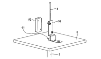
- FIG. 3 is an enlarged perspective view of a portion of the fixing member 5 according to the preferred embodiment of the present invention.
- the fixing member 5 includes a main body 51 fixed to the partition wall 6 and a fixing piece 52 that can be joined to the main body 51.
- the conducting wire 4 is sandwiched and fixed between the main body 51 and the fixing piece 52.
- the conductor 4 is sandwiched between the main body 51 and the fixing piece 52 and receives compressive stress from both. Since a static frictional force due to compressive stress is generated between the surface of the conducting wire 4 and the surfaces of the main body 51 and the fixing piece 52, the conducting wire 4 is fixed to the fixing member 5 and its position can be easily positioned. I can't move.
- the main body 51 may be detachably fixed to the partition wall 6 by, for example, screwing, or may be fixed by welding, for example. Even if the fixing between the main body 51 and the partition wall 6 is solid such as welding, if the fixing of the conducting wire 4 by the main body 51 and the fixing piece 52 is removable, the effect according to the present invention can be obtained. Obtainable.
- the fixing member 5 illustrated in FIG. 3 the main body 51 and the fixing piece 52 are fastened by two male screws inserted into the holes provided in the main body 51 and two screw holes provided in the fixing piece 52. It is configured to be possible.
- the conductor 4 can be detachably fixed to the fixing member 5 by screwing the male screw into the screw hole while the conductor 4 is sandwiched between the main body 51 and the fixing piece 52.
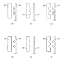
- either one of the main body 51 or the fixed piece 52 is provided with a fixing hole 53, and the main body 51 or the fixed piece 52 is provided with a fixing hole 53.
- the other of them is provided with a convex portion 54 at a position corresponding to the position of the fixing hole 53, and by joining the fixing piece 52 to the main body 51, the conducting wire 4 is pushed out in the direction of the fixing hole 53 by the convex portion 54 and fixed. Will be done.
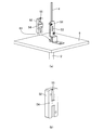
- FIG. 5A shows a state before the conductor 4 is fixed to the fixing member 5.
- the fixing hole 53 is provided at the center of the largest surface of the main body 51.
- FIGS. 1 and 2 show the final state in which the conducting wire 4 is fixed by the fixing member 5.
- the conducting wire 4 is pushed out in the direction of the fixing hole 53 by the convex portion 54 and deformed.
- the conductor 4 can be fixed more firmly than in the case where the conductor 4 is fixed only by the above-mentioned static frictional force. ..
- the fixing hole 53 is provided in the main body 51 and the convex portion 54 is provided in the fixing piece 52.
- the fixing hole 53 is provided in the fixing piece 52 and the convex portion 52. Even when the 54 is provided on the main body 51, it can be firmly fixed in exactly the same manner as in the above-described embodiment.
- two grooves formed so as to be orthogonal to the relief groove for accommodating the conducting wire 4 are formed above and below the convex portion 54.
- the configurations of the main body 51 and the fixing piece 52 are not limited to the above-mentioned configurations, and are not particularly limited as long as the conductor 4 can be sandwiched between the main body 51 and the fixing piece 52 and fixed.
- the configuration of the sensor 1 according to the present invention does not include the container, but the sensor 1 is configured on the premise that it is used by being fixed to the partition wall 6 of the container.
- the container for fixing the sensor 1 according to the present invention may be any container as long as it is a container having a partition wall 6 that separates the outside from the inside.
- a tank for storing liquid or gas, a furnace chamber of a heat treatment furnace or a reaction furnace, and the like can correspond to the container in the present invention.
- the protective tube 2 constituting the sensor 1 according to the present invention is fixed to a through hole 61 formed in the partition wall 6 of the container.
- the position of the through hole 61 in the partition wall 6 constituting the container is provided as close as possible to the position in the container where the internal information is to be detected by the sensor 1.
- the partition wall 6 shown in FIGS. 1 to 3 and 5 is obtained by cutting out only a portion of the partition wall 6 constituting the container to which the protective tube 2 and the fixing member 5 are fixed.
- the shape of the partition wall 6 is shown as a quadrangle, but this shape has no particular meaning. In these figures, the side on which the protective tube 2 is fixed corresponds to the inside of the container, and the side on which the fixing member 5 is fixed corresponds to the outside of the container.
- the end (outer end) of the protective tube 2 that is open toward the outside of the container does not necessarily have to be flush with the partition wall 6, and may protrude from the partition wall 6. Further, as long as the application of the container to which the sensor 1 is applied allows, the entire fixing member 5 does not necessarily have to be located outside the container. That is, the configuration of the fixing member 5 is not particularly limited as long as it is fixed to the partition wall 6 and the conducting wire 4 can be detachably fixed outside the protective tube 2.
- the container is an airtight container
- the protective tube 2 is inseparably fixed to the partition wall 6.
- the entire container should be airtightly constructed without any gaps to prevent leakage of the contents. Is preferable.
- it is effective to integrally configure the through hole 61 formed in the partition wall 6 of the container and the protective tube 2 of the sensor 1 inseparably.
- it is conceivable to weld the partition wall 6 of the container made of metal or alloy and the protective tube 2, or to weld the partition wall 6 of the container made of thermoplastic resin and the protective tube 2. ..
- the end (inner end) of the protective tube 2 located inside the container is airtightly closed.
- FIG. 6 is a partial cross-sectional view of the sensor 1 according to such an embodiment of the present invention.
- the sensor 1 illustrated in FIG. 6 further includes a stopper 22 that defines the upper limit position of the float 7 in addition to the stopper 21 that defines the lower limit position of the float 7, and the tip side of the detection unit 3 inside the protection tube 2 ( It has the same configuration as the sensor 1 illustrated in FIG. 2, except that the spacer 31 is further provided on the inner end side).
- the spacer 31 is arranged inside the protective tube 2 on the side of the inner end of the detection unit 3 (the end on the side of the protective tube 2 located inside the container). Has been done. Therefore, the detection unit 3 can be reliably held at a desired position by lowering the detection unit 3 inside the protection tube 2 until the spacer 31 having a predetermined length abuts on the inner end of the protection tube 2. can. When changing the position of the detection unit 3 inside the protection tube 2, the length of the spacer 31 may be changed.
- FIG. 7 is a perspective view showing the sensor 1'according to the prior art.
- the sensor 1'according to the prior art exemplified in FIG. 7 determines the position of the liquid level of the liquid stored inside the container, similarly to the sensor 1 according to the preferred embodiment of the present invention shown in FIG. It is configured as a liquid level sensor to detect.
- the sensor 1'shown in FIG. 7 determines the position of the liquid level of the liquid stored inside the container, similarly to the sensor 1 according to the preferred embodiment of the present invention shown in FIG. It is configured as a liquid level sensor to detect.
- the configurations of the protective tube 2, the conducting wire 4, the partition wall 6 and the float 7, and the detection unit 3 not shown in the figure are the sensors shown in FIGS. 1 and 2. Since it is the same as 1, the same symbol is used here and the description thereof will be omitted. The only difference in the configuration of the sensor 1'and the sensor 1 is that the sensor 1'lacks the fixing member 5 included in the sensor 1.
- the adhesive after curing is very hard, even if the conductor 4 is to be peeled off from the protective tube 2 for the purpose of exchanging the detection unit 3 and the conductor 4, the conductor 4 is not destroyed. Is almost impossible to do.
- a silicone sealant or the like which is softer than the above-mentioned epoxy resin adhesive, can also be used as the adhesive.
- the conducting wire 4 is adhered to the inside of the protective tube 2, it is not easy to remove the adhesive filled in the narrow space and take out the conducting wire 4.
- the adhesion of the conducting wire 4 to the protective tube 2 at the upper end (outer end) of the protective tube 2 is not made so strong, and the conducting wire 4 can be easily made from the protective tube 2. It is conceivable that it can be removed. However, in this case, depending on the size and / or weight of the detection unit 3, the detection unit 3 may move inside the protective tube 2 or the position of the detection unit 3 may not be determined. When the detection unit 3 and the protection tube 2 are adhered to prevent this, when the detection unit 3 is pulled out from the protection tube 2 by pulling the lead wire 4, the detection unit 3 does not come off from the inside of the protection tube 2 and detects it.
- the conducting wire 4 is attached to the fixing member 5 (which is a separate member) independent of the protective tube 2 outside the protective tube 2.
- the detection unit 3 can be housed in a predetermined position of the protection tube 2. Since the fixing of the conducting wire 4 to the fixing member 5 can be easily released, the failed detection unit 3 can be replaced with a new one or the position of the detection unit 3 in the protective tube 2 can be easily changed as compared with the conventional technique. It can be adjusted after the fact.
- the sensor 1 when the inside of the container becomes high pressure and / or when a chemical substance harmful to the human body is stored in the container, the sensor 1 is applied to the airtight container and the protective tube is inseparably integrated with the partition wall 6 of the container. By fixing 2 and closing the inner end of the protective tube 2, leakage of the contents can be reliably prevented. Further, the sensor 1 has a simpler and more compact configuration than the sensor according to the prior art. Therefore, according to the sensor 1, the above-mentioned effects can be achieved while avoiding problems such as an increase in manufacturing cost and a decrease in design degree of freedom.
- the present invention proposes a sensor 1 suitable as a sensor that can be attached to a container in which the protective tube 2 is inseparably fixed to the partition wall 6 of the container.
- the present invention is not limited to the embodiment in which the protective tube 2 is inseparably fixed to the partition wall 6, and can be implemented in various forms within a range that does not deviate from the technical idea thereof.
Landscapes
- Physics & Mathematics (AREA)
- General Physics & Mathematics (AREA)
- Fluid Mechanics (AREA)
- Nonlinear Science (AREA)
- Condensed Matter Physics & Semiconductors (AREA)
- Measurement Of Levels Of Liquids Or Fluent Solid Materials (AREA)
- Level Indicators Using A Float (AREA)
Priority Applications (4)
| Application Number | Priority Date | Filing Date | Title |
|---|---|---|---|
| US17/910,505 US12339155B2 (en) | 2020-03-25 | 2021-02-19 | Sensor |
| JP2022509415A JP7505545B2 (ja) | 2020-03-25 | 2021-02-19 | センサ |
| CN202180016095.4A CN115135972A (zh) | 2020-03-25 | 2021-02-19 | 传感器 |
| KR1020227032837A KR20220156558A (ko) | 2020-03-25 | 2021-02-19 | 센서 |
Applications Claiming Priority (2)
| Application Number | Priority Date | Filing Date | Title |
|---|---|---|---|
| JP2020-053575 | 2020-03-25 | ||
| JP2020053575 | 2020-03-25 |
Publications (1)
| Publication Number | Publication Date |
|---|---|
| WO2021192754A1 true WO2021192754A1 (ja) | 2021-09-30 |
Family
ID=77891159
Family Applications (1)
| Application Number | Title | Priority Date | Filing Date |
|---|---|---|---|
| PCT/JP2021/006277 Ceased WO2021192754A1 (ja) | 2020-03-25 | 2021-02-19 | センサ |
Country Status (5)
| Country | Link |
|---|---|
| US (1) | US12339155B2 (https=) |
| JP (1) | JP7505545B2 (https=) |
| KR (1) | KR20220156558A (https=) |
| CN (1) | CN115135972A (https=) |
| WO (1) | WO2021192754A1 (https=) |
Families Citing this family (1)
| Publication number | Priority date | Publication date | Assignee | Title |
|---|---|---|---|---|
| CN117968799B (zh) * | 2024-03-29 | 2024-06-14 | 河南厚鼎建设工程有限公司 | 一种城市内涝积水检测装置 |
Citations (5)
| Publication number | Priority date | Publication date | Assignee | Title |
|---|---|---|---|---|
| JPS5572451A (en) * | 1978-11-21 | 1980-05-31 | Nippon Air Brake Co Ltd | Reservoir with liquid level detector |
| JPH08128900A (ja) * | 1994-10-31 | 1996-05-21 | Aisan Ind Co Ltd | 液体温度センサ及びその取付装置 |
| JP2000280887A (ja) * | 1999-03-31 | 2000-10-10 | Nissin Kogyo Co Ltd | 流体リザーバ用スイッチユニット |
| US6195013B1 (en) * | 1999-11-09 | 2001-02-27 | Breed Automotive Technology, Inc. | Fluid level sensor |
| JP2002071432A (ja) * | 2000-08-30 | 2002-03-08 | Mitsubishi Electric Corp | 冷凍サイクル用液面検知計及び冷凍サイクル |
Family Cites Families (13)
| Publication number | Priority date | Publication date | Assignee | Title |
|---|---|---|---|---|
| US3141062A (en) * | 1963-08-08 | 1964-07-14 | Illinois Tool Works | Arcuate slot strain relief grommet |
| US3493205A (en) * | 1968-06-26 | 1970-02-03 | Thomas & Betts Corp | Bushing with strain relief |
| JPH05288593A (ja) | 1992-04-10 | 1993-11-02 | Meidensha Corp | 単一形多極電極を用いた液位計 |
| JP3675694B2 (ja) | 2000-04-14 | 2005-07-27 | ホシザキ電機株式会社 | 貯液タンク |
| JP2001356041A (ja) | 2000-06-13 | 2001-12-26 | Yazaki Corp | 電気防爆対応の検出器 |
| JP3979934B2 (ja) | 2002-12-05 | 2007-09-19 | Jpn株式会社 | 多点検出型磁気近接スイッチ |
| KR20090095781A (ko) * | 2008-03-06 | 2009-09-10 | 임형준 | 단위 회전자석을 이용한 유량 측정장치 |
| GB2459146A (en) * | 2008-04-10 | 2009-10-21 | Calder Ltd | Cable retention bracket |
| JP5150422B2 (ja) | 2008-09-10 | 2013-02-20 | 日精樹脂工業株式会社 | タンクの液面検出装置 |
| CN102012250B (zh) | 2009-12-02 | 2012-05-30 | 范序政 | 磁浮子液位传感器的分体式装、拆方法及装置 |
| JP2018152482A (ja) * | 2017-03-14 | 2018-09-27 | オムロン株式会社 | ケーブル抜け止め構造 |
| US11820985B2 (en) | 2019-03-26 | 2023-11-21 | University Of Massachusetts | Modified oligonucleotides with increased stability |
| CN210293367U (zh) * | 2019-08-19 | 2020-04-10 | 上海振华重工启东海洋工程股份有限公司 | 一种液位传感器保护工装 |
-
2021
- 2021-02-19 US US17/910,505 patent/US12339155B2/en active Active
- 2021-02-19 KR KR1020227032837A patent/KR20220156558A/ko active Pending
- 2021-02-19 WO PCT/JP2021/006277 patent/WO2021192754A1/ja not_active Ceased
- 2021-02-19 JP JP2022509415A patent/JP7505545B2/ja active Active
- 2021-02-19 CN CN202180016095.4A patent/CN115135972A/zh active Pending
Patent Citations (5)
| Publication number | Priority date | Publication date | Assignee | Title |
|---|---|---|---|---|
| JPS5572451A (en) * | 1978-11-21 | 1980-05-31 | Nippon Air Brake Co Ltd | Reservoir with liquid level detector |
| JPH08128900A (ja) * | 1994-10-31 | 1996-05-21 | Aisan Ind Co Ltd | 液体温度センサ及びその取付装置 |
| JP2000280887A (ja) * | 1999-03-31 | 2000-10-10 | Nissin Kogyo Co Ltd | 流体リザーバ用スイッチユニット |
| US6195013B1 (en) * | 1999-11-09 | 2001-02-27 | Breed Automotive Technology, Inc. | Fluid level sensor |
| JP2002071432A (ja) * | 2000-08-30 | 2002-03-08 | Mitsubishi Electric Corp | 冷凍サイクル用液面検知計及び冷凍サイクル |
Also Published As
| Publication number | Publication date |
|---|---|
| KR20220156558A (ko) | 2022-11-25 |
| CN115135972A (zh) | 2022-09-30 |
| JP7505545B2 (ja) | 2024-06-25 |
| JPWO2021192754A1 (https=) | 2021-09-30 |
| US20230136617A1 (en) | 2023-05-04 |
| US12339155B2 (en) | 2025-06-24 |
Similar Documents
| Publication | Publication Date | Title |
|---|---|---|
| KR102015153B1 (ko) | 쌍극 쌍투 근접 스위치 | |
| JP4681205B2 (ja) | ヘリウムまたは水素のためのセンサを備えた漏洩検出装置のためのテストガスディテクタ | |
| KR100983814B1 (ko) | 압력반응 금속다이아프램을 구비한 압력센서 | |
| US7817010B2 (en) | Temperature probe and method of making the same | |
| EP3401658A1 (en) | Temperature sensor | |
| NO934326L (no) | Elektrokjemisk celle i kombinasjon med en tilstandsindikator | |
| EP3712585A1 (en) | Pressure sensor | |
| WO2021192754A1 (ja) | センサ | |
| JP2006078417A (ja) | 圧力センサ | |
| JP6651078B1 (ja) | フロート式レベル計 | |
| JP4364276B2 (ja) | 海底中継装置のフィードスルー及び海底中継装置 | |
| US11549907B2 (en) | Ceramic applied electronic device and connector | |
| US4379248A (en) | Ionization chamber having coaxially arranged cylindrical electrodes | |
| JP2015052504A (ja) | 圧力検出装置及びその製造方法 | |
| JP4832044B2 (ja) | 温度検出体 | |
| JP4654293B2 (ja) | グリッドセンサー | |
| US7318273B2 (en) | Method for producing pH probes | |
| KR101345194B1 (ko) | 스위칭 기능을 구비한 밀봉형 커넥터 어셈블리 | |
| JP2022003357A (ja) | シース型測温抵抗体の製造方法 | |
| JP4567725B2 (ja) | 圧電素子用の接点ピンを配置する方法並びにスリーブ及びアクチュエータユニット | |
| CN217237065U (zh) | 压力传感器 | |
| CN109931992B (zh) | 电磁流量计的电位检测用电极 | |
| US3382107A (en) | Sealing device for an electrochemical cell | |
| CN111279170A (zh) | 压力传感器 | |
| CN121933151A (zh) | 一种传感器 |
Legal Events
| Date | Code | Title | Description |
|---|---|---|---|
| 121 | Ep: the epo has been informed by wipo that ep was designated in this application |
Ref document number: 21775272 Country of ref document: EP Kind code of ref document: A1 |
|
| ENP | Entry into the national phase |
Ref document number: 2022509415 Country of ref document: JP Kind code of ref document: A |
|
| NENP | Non-entry into the national phase |
Ref country code: DE |
|
| 122 | Ep: pct application non-entry in european phase |
Ref document number: 21775272 Country of ref document: EP Kind code of ref document: A1 |
|
| WWG | Wipo information: grant in national office |
Ref document number: 17910505 Country of ref document: US |