WO2021192754A1 - Sensor - Google Patents
Sensor Download PDFInfo
- Publication number
- WO2021192754A1 WO2021192754A1 PCT/JP2021/006277 JP2021006277W WO2021192754A1 WO 2021192754 A1 WO2021192754 A1 WO 2021192754A1 JP 2021006277 W JP2021006277 W JP 2021006277W WO 2021192754 A1 WO2021192754 A1 WO 2021192754A1
- Authority
- WO
- WIPO (PCT)
- Prior art keywords
- protective tube
- container
- detection unit
- fixed
- sensor
- Prior art date
Links
Images


Classifications
-
- G—PHYSICS
- G01—MEASURING; TESTING
- G01D—MEASURING NOT SPECIALLY ADAPTED FOR A SPECIFIC VARIABLE; ARRANGEMENTS FOR MEASURING TWO OR MORE VARIABLES NOT COVERED IN A SINGLE OTHER SUBCLASS; TARIFF METERING APPARATUS; MEASURING OR TESTING NOT OTHERWISE PROVIDED FOR
- G01D11/00—Component parts of measuring arrangements not specially adapted for a specific variable
- G01D11/24—Housings ; Casings for instruments
- G01D11/245—Housings for sensors
-
- G—PHYSICS
- G01—MEASURING; TESTING
- G01F—MEASURING VOLUME, VOLUME FLOW, MASS FLOW OR LIQUID LEVEL; METERING BY VOLUME
- G01F23/00—Indicating or measuring liquid level or level of fluent solid material, e.g. indicating in terms of volume or indicating by means of an alarm
- G01F23/30—Indicating or measuring liquid level or level of fluent solid material, e.g. indicating in terms of volume or indicating by means of an alarm by floats
- G01F23/64—Indicating or measuring liquid level or level of fluent solid material, e.g. indicating in terms of volume or indicating by means of an alarm by floats of the free float type without mechanical transmission elements
- G01F23/72—Indicating or measuring liquid level or level of fluent solid material, e.g. indicating in terms of volume or indicating by means of an alarm by floats of the free float type without mechanical transmission elements using magnetically actuated indicating means
- G01F23/74—Indicating or measuring liquid level or level of fluent solid material, e.g. indicating in terms of volume or indicating by means of an alarm by floats of the free float type without mechanical transmission elements using magnetically actuated indicating means for sensing changes in level only at discrete points
-
- G—PHYSICS
- G01—MEASURING; TESTING
- G01F—MEASURING VOLUME, VOLUME FLOW, MASS FLOW OR LIQUID LEVEL; METERING BY VOLUME
- G01F23/00—Indicating or measuring liquid level or level of fluent solid material, e.g. indicating in terms of volume or indicating by means of an alarm
- G01F23/30—Indicating or measuring liquid level or level of fluent solid material, e.g. indicating in terms of volume or indicating by means of an alarm by floats
- G01F23/64—Indicating or measuring liquid level or level of fluent solid material, e.g. indicating in terms of volume or indicating by means of an alarm by floats of the free float type without mechanical transmission elements
- G01F23/72—Indicating or measuring liquid level or level of fluent solid material, e.g. indicating in terms of volume or indicating by means of an alarm by floats of the free float type without mechanical transmission elements using magnetically actuated indicating means
-
- G—PHYSICS
- G01—MEASURING; TESTING
- G01D—MEASURING NOT SPECIALLY ADAPTED FOR A SPECIFIC VARIABLE; ARRANGEMENTS FOR MEASURING TWO OR MORE VARIABLES NOT COVERED IN A SINGLE OTHER SUBCLASS; TARIFF METERING APPARATUS; MEASURING OR TESTING NOT OTHERWISE PROVIDED FOR
- G01D11/00—Component parts of measuring arrangements not specially adapted for a specific variable
- G01D11/30—Supports specially adapted for an instrument; Supports specially adapted for a set of instruments
-
- G—PHYSICS
- G01—MEASURING; TESTING
- G01F—MEASURING VOLUME, VOLUME FLOW, MASS FLOW OR LIQUID LEVEL; METERING BY VOLUME
- G01F23/00—Indicating or measuring liquid level or level of fluent solid material, e.g. indicating in terms of volume or indicating by means of an alarm
- G01F23/30—Indicating or measuring liquid level or level of fluent solid material, e.g. indicating in terms of volume or indicating by means of an alarm by floats
- G01F23/56—Indicating or measuring liquid level or level of fluent solid material, e.g. indicating in terms of volume or indicating by means of an alarm by floats using elements rigidly fixed to, and rectilinearly moving with, the floats as transmission elements
- G01F23/60—Indicating or measuring liquid level or level of fluent solid material, e.g. indicating in terms of volume or indicating by means of an alarm by floats using elements rigidly fixed to, and rectilinearly moving with, the floats as transmission elements using electrically actuated indicating means
-
- G—PHYSICS
- G01—MEASURING; TESTING
- G01F—MEASURING VOLUME, VOLUME FLOW, MASS FLOW OR LIQUID LEVEL; METERING BY VOLUME
- G01F23/00—Indicating or measuring liquid level or level of fluent solid material, e.g. indicating in terms of volume or indicating by means of an alarm
- G01F23/30—Indicating or measuring liquid level or level of fluent solid material, e.g. indicating in terms of volume or indicating by means of an alarm by floats
- G01F23/56—Indicating or measuring liquid level or level of fluent solid material, e.g. indicating in terms of volume or indicating by means of an alarm by floats using elements rigidly fixed to, and rectilinearly moving with, the floats as transmission elements
- G01F23/62—Indicating or measuring liquid level or level of fluent solid material, e.g. indicating in terms of volume or indicating by means of an alarm by floats using elements rigidly fixed to, and rectilinearly moving with, the floats as transmission elements using magnetically actuated indicating means
-
- G—PHYSICS
- G01—MEASURING; TESTING
- G01K—MEASURING TEMPERATURE; MEASURING QUANTITY OF HEAT; THERMALLY-SENSITIVE ELEMENTS NOT OTHERWISE PROVIDED FOR
- G01K1/00—Details of thermometers not specially adapted for particular types of thermometer
- G01K1/08—Protective devices, e.g. casings
-
- G—PHYSICS
- G01—MEASURING; TESTING
- G01K—MEASURING TEMPERATURE; MEASURING QUANTITY OF HEAT; THERMALLY-SENSITIVE ELEMENTS NOT OTHERWISE PROVIDED FOR
- G01K1/00—Details of thermometers not specially adapted for particular types of thermometer
- G01K1/14—Supports; Fastening devices; Arrangements for mounting thermometers in particular locations
-
- G—PHYSICS
- G01—MEASURING; TESTING
- G01K—MEASURING TEMPERATURE; MEASURING QUANTITY OF HEAT; THERMALLY-SENSITIVE ELEMENTS NOT OTHERWISE PROVIDED FOR
- G01K7/00—Measuring temperature based on the use of electric or magnetic elements directly sensitive to heat ; Power supply therefor, e.g. using thermoelectric elements
- G01K7/02—Measuring temperature based on the use of electric or magnetic elements directly sensitive to heat ; Power supply therefor, e.g. using thermoelectric elements using thermoelectric elements, e.g. thermocouples
-
- G—PHYSICS
- G01—MEASURING; TESTING
- G01K—MEASURING TEMPERATURE; MEASURING QUANTITY OF HEAT; THERMALLY-SENSITIVE ELEMENTS NOT OTHERWISE PROVIDED FOR
- G01K7/00—Measuring temperature based on the use of electric or magnetic elements directly sensitive to heat ; Power supply therefor, e.g. using thermoelectric elements
- G01K7/16—Measuring temperature based on the use of electric or magnetic elements directly sensitive to heat ; Power supply therefor, e.g. using thermoelectric elements using resistive elements
- G01K7/22—Measuring temperature based on the use of electric or magnetic elements directly sensitive to heat ; Power supply therefor, e.g. using thermoelectric elements using resistive elements the element being a non-linear resistance, e.g. thermistor
-
- G—PHYSICS
- G01—MEASURING; TESTING
- G01R—MEASURING ELECTRIC VARIABLES; MEASURING MAGNETIC VARIABLES
- G01R33/00—Arrangements or instruments for measuring magnetic variables
- G01R33/02—Measuring direction or magnitude of magnetic fields or magnetic flux
- G01R33/06—Measuring direction or magnitude of magnetic fields or magnetic flux using galvano-magnetic devices
- G01R33/07—Hall effect devices
Landscapes
- Physics & Mathematics (AREA)
- General Physics & Mathematics (AREA)
- Fluid Mechanics (AREA)
- Nonlinear Science (AREA)
- Condensed Matter Physics & Semiconductors (AREA)
- Measurement Of Levels Of Liquids Or Fluent Solid Materials (AREA)
Abstract
This sensor is provided with a protection tube which is fixed in a through-hole formed in the partition wall of a container, a detection unit which is arranged inside of the protection tube, a lead wire which is connected to the detection unit inside of the protection tube, and a fixed member which is fixed to the partition wall, wherein the lead wire is detachably fixed to the fixed member outside of the protection tube. In one favorable embodiment, the container is an airtight container and the protection tube is integrally and inseparably fixed to the partition wall. In this way, a sensor provided with a detection unit and a lead wire inside of a protection tube fixed to the partition wall of the container can be provided which, with a simple structure, facilitates partial replacement of members during failure and/or adjustment of the position of the detection unit.
Description
本発明は、センサに関する。
The present invention relates to a sensor.
隔壁によって構成された容器の内部の状態を知るために、様々な種類のセンサが用いられる。例えば、容器の内部の温度を知るためには温度センサが用いられ、容器に貯蔵された液体の液面の位置を知るためには液位センサが用いられる。これらのセンサは、容器の内部における特定の位置に配置され、その位置における温度及び液体の有無等の状態を検知する。
Various types of sensors are used to know the internal condition of the container composed of partition walls. For example, a temperature sensor is used to know the temperature inside the container, and a liquid level sensor is used to know the position of the liquid level of the liquid stored in the container. These sensors are arranged at a specific position inside the container and detect the state such as the temperature and the presence or absence of liquid at that position.
上記目的のために、容器に挿入された保護管の内部に検知部を収納し、検知部に接続された導線を介して電気信号を容器の外部に取り出すタイプのセンサが知られている。保護管を容器の隔壁に固定することによって、検知部の位置を容器内の任意の位置に固定することができる。また、容器に貯蔵された液体及び/又はガス等が保護管の内部に入らないように保護管を構成することにより、当該液体及び/又はガスと検知部とが直接接触しないようにすることもできる。
For the above purpose, there is known a type of sensor in which a detection unit is housed inside a protective tube inserted in a container and an electric signal is taken out of the container via a conducting wire connected to the detection unit. By fixing the protective tube to the partition wall of the container, the position of the detection unit can be fixed at any position in the container. In addition, by configuring the protective tube so that the liquid and / or gas stored in the container does not enter the inside of the protective tube, the liquid and / or gas and the detection unit can be prevented from coming into direct contact with each other. can.
例えば、特許文献1に記載された貯液タンクが備える液位センサは、タンクの蓋から内部に吊り下げられた案内パイプ(保護管)と、案内パイプの内部に収納された上下2個のリードスイッチ(検知部)と、永久磁石が装着された昇降自由なフロートと、によって構成されている。案内パイプの上端からは、リードスイッチに接続されたリード線(導線)が引き出されている。案内パイプの上端付近に取付溝を設け、タンクの蓋に設けられた筒部(貫通穴)に案内パイプの上端を挿入し、取付溝に止め輪を嵌め着けることによって、液位センサ全体が交換可能な状態でタンク内に取り付けられている。
For example, the liquid level sensor included in the liquid storage tank described in Patent Document 1 includes a guide pipe (protective pipe) suspended inside from the tank lid and two upper and lower leads housed inside the guide pipe. It consists of a switch (detector) and a float that is equipped with a permanent magnet and can move up and down freely. A lead wire (lead wire) connected to a reed switch is pulled out from the upper end of the guide pipe. A mounting groove is provided near the upper end of the guide pipe, the upper end of the guide pipe is inserted into the cylinder (through hole) provided in the lid of the tank, and a retaining ring is fitted in the mounting groove to replace the entire liquid level sensor. It is installed in the tank when possible.
また、特許文献2に記載された検出器においては、一方の端部が閉塞された管体中に挿入された検出部に接続された導線が当該管体の他方の端部から引き出され、当該他方の端部には合成樹脂材が充填されて、耐圧防爆構造が達成されている。これにより、バリアリレー等の機器類を必要とすること無く電気防爆対応の検出器を提供することができる。
Further, in the detector described in Patent Document 2, a conducting wire connected to a detection portion inserted into a tube body in which one end is closed is pulled out from the other end of the tube body, and the present invention is described. The other end is filled with a synthetic resin material to achieve a pressure resistant explosion-proof structure. This makes it possible to provide an electric explosion-proof detector without the need for equipment such as a barrier relay.
更に、特許文献3に記載された多点検出型磁気近接スイッチにおいては、ハウジングの開放側の端部内に配置されたブッシュに形成された貫通孔及びハウジング内に形成された複数のガイド孔に、複数の磁気感応部及びコードがそれぞれ挿入され、締め付け部材によってブッシュが圧縮される。これによれば、従来よりも簡略化された構造により、ブッシュの弾性変形によってコードを固定して、磁気感応部を任意の位置に固定することができる。
Further, in the multipoint detection type magnetic proximity switch described in Patent Document 3, through holes formed in bushes arranged in the open end of the housing and a plurality of guide holes formed in the housing are provided. A plurality of magnetic sensitive parts and cords are inserted respectively, and the bush is compressed by the tightening member. According to this, the cord can be fixed by the elastic deformation of the bush due to the structure simplified as compared with the conventional case, and the magnetic sensitive portion can be fixed at an arbitrary position.
上述したように、保護管を備えたセンサは、容器の内部の状態を知るために必要不可欠な装備である。ところで、センサの故障及び/又は点検の際にはセンサを容器から取り外したり新たなセンサを容器に取り付けたりする必要が生ずる場合がある。また、例えばセンサが取り付けられる容器の用途及び/又は使用条件の変更等に伴ってセンサの検知部の位置を調整(変更を含む)する必要が生ずる場合がある。しかしながら、上述した特許文献1及び特許文献2においては、このようなセンサの脱着及び/又は検知部の位置調整については何ら考慮も言及もなされていない。特許文献3に記載された多点検出型磁気近接スイッチにおいては検知部の位置調整が企図されている。しかしながら、従来よりも簡略化された構造とはいえ、磁気感応部及びコードの形状及び数に応じた専用のブッシュ及びガイド孔を設ける必要があり、構造の複雑化及び大型化を招くおそれがある。その結果、例えば製造コストの増大及び設計上の自由度の低下等の問題が生ずるおそれがある。
As mentioned above, a sensor equipped with a protective tube is an indispensable equipment for knowing the internal condition of the container. By the way, in the case of sensor failure and / or inspection, it may be necessary to remove the sensor from the container or attach a new sensor to the container. Further, for example, it may be necessary to adjust (including change) the position of the detection unit of the sensor due to a change in the use and / or usage conditions of the container to which the sensor is attached. However, in the above-mentioned Patent Documents 1 and 2, no consideration or reference is made to the attachment / detachment of the sensor and / or the position adjustment of the detection unit. In the multipoint detection type magnetic proximity switch described in Patent Document 3, the position adjustment of the detection unit is intended. However, although the structure is simpler than the conventional one, it is necessary to provide a dedicated bush and guide hole according to the shape and number of the magnetic sensitive portion and the cord, which may lead to the complexity and size of the structure. .. As a result, problems such as an increase in manufacturing cost and a decrease in design freedom may occur.
また、何れの先行技術においても、保護管を固定するための穴が容器の隔壁に設けられるため、容器の内容物が穴と保護管の隙間から容器の外部に漏れ出すおそれがある。そこで、容器の内部が高圧になる場合及び/又は人体に有害な化学物質を容器に貯蔵する場合等においては、容器全体を隙間無く気密に構成して、内容物の漏出を防ぐ必要がある。この目的のためには、容器の隔壁に形成された穴とセンサの保護管とを不可分一体に構成することが有効である。具体的には、例えば、金属又は合金からなる容器の隔壁と保護管とを溶接したり、熱可塑性樹脂からなる容器の隔壁と保護管とを溶着したりすること等が考えられる。
Further, in any of the prior arts, since the hole for fixing the protective tube is provided in the partition wall of the container, the contents of the container may leak to the outside of the container through the gap between the hole and the protective tube. Therefore, when the inside of the container becomes high pressure and / or when chemical substances harmful to the human body are stored in the container, it is necessary to make the entire container airtight without any gaps to prevent leakage of the contents. For this purpose, it is effective to integrally configure the hole formed in the partition wall of the container and the protective tube of the sensor inseparably. Specifically, for example, it is conceivable to weld the partition wall of the container made of metal or alloy and the protective tube, or to weld the partition wall of the container made of thermoplastic resin and the protective tube.
ところが、上述したように容器の穴とセンサの保護管とを不可分一体に構成した場合は、容器と保護管とを分離することができないので、センサが故障してもセンサ全体を保護管ごと交換することができない。そこで、容器に固定された保護管の内部に接着剤等を用いて検知部及び導線を仮留めして使用し、必要な場合は検知部及び導線を交換することが考えられる。ところが、接着剤によって固定した場合は、検知部及び導線を交換しようとしたり、検知部の位置を調整しようとしたりする度に、接着剤による固定を解除しなければならない。このため、交換及び/又は調整の作業が煩雑になるという新たな問題が発生する。
However, if the hole in the container and the protective tube of the sensor are inseparably integrated as described above, the container and the protective tube cannot be separated, so even if the sensor fails, the entire sensor is replaced together with the protective tube. Can not do it. Therefore, it is conceivable to temporarily fasten the detection unit and the conductor with an adhesive or the like inside the protective tube fixed to the container, and replace the detection unit and the conductor if necessary. However, when it is fixed by the adhesive, the fixing by the adhesive must be released every time the detection unit and the lead wire are exchanged or the position of the detection unit is adjusted. For this reason, a new problem arises in which the work of replacement and / or adjustment becomes complicated.
本発明は、上述した様々な課題に鑑みてなされたものであり、容器の隔壁に固定された保護管を備えるセンサであって、単純な構造により、故障時の部分的な部材交換及び/又は検知部の位置の調整等を容易に行うことができるセンサを提供することを目的とする。
The present invention has been made in view of the various problems described above, and is a sensor provided with a protective tube fixed to a partition wall of a container. An object of the present invention is to provide a sensor capable of easily adjusting the position of a detection unit.
本発明に係るセンサ(以降、「本発明センサ」と称呼される場合がある。)は、保護管、検知部、導線及び固定部材を備えるセンサである。保護管は、容器の隔壁に形成された貫通穴に固定され、当該保護管の一方の端である内端が容器の内部に位置し、当該保護管の他方の端である外端が容器の外部に向かって開いている、検知部は、保護管の内部に収納されている。導線は、一方の端が保護管の内部で検知部に接続され、他方の端が上記外端から外部に向かって突出している。固定部材は、容器の隔壁に固定され、保護管の外部において導線を着脱可能に固定するように構成されている。
The sensor according to the present invention (hereinafter, may be referred to as "the sensor of the present invention") is a sensor including a protective tube, a detection unit, a conducting wire, and a fixing member. The protective tube is fixed in a through hole formed in the partition wall of the container, the inner end which is one end of the protective tube is located inside the container, and the outer end which is the other end of the protective tube is the container. The detector, which is open to the outside, is housed inside the protective tube. One end of the conductor is connected to the detection unit inside the protective tube, and the other end projects outward from the outer end. The fixing member is fixed to the partition wall of the container, and is configured to detachably fix the conducting wire outside the protective tube.
本発明センサにおいては、保護管の容器の外部に向かって開いている側の端(外端)から突出する導線を手でつかんで保護管の軸線方向に抜き差しすることができる。これにより、例えば、故障した検知部及び導線を取り出して正常なものと交換したり、導線と接続された検知部の位置を任意の位置に調整したりすることができる。検知部の交換及び/又は位置調整が完了したら、その状態において固定部材に導線を着脱可能に固定することにより、導線の移動を妨げ、導線と接続された検知部の位置を調整後の位置に保持することができる。
In the sensor of the present invention, the lead wire protruding from the end (outer end) on the side of the protective tube that is open toward the outside can be grasped by hand and inserted and removed in the axial direction of the protective tube. Thereby, for example, the failed detection unit and the conducting wire can be taken out and replaced with a normal one, or the position of the detecting unit connected to the conducting wire can be adjusted to an arbitrary position. After the replacement and / or position adjustment of the detection unit is completed, the conductor is detachably fixed to the fixing member in that state to prevent the conductor from moving, and the position of the detection unit connected to the conductor is moved to the adjusted position. Can be held.
また、検知部は、サーミスタ、測温抵抗体、熱電対、ホール素子及びリードスイッチからなる群から選択される1又は2以上の検知部であってもよい。更に、本発明センサが適用される容器は貯液タンクであってもよい。この場合、検知部をホール素子又はリードスイッチとし、永久磁石を備え且つ保護管の長手方向に移動可能なフロートを更に備える液位センサとして構成することができる。
Further, the detection unit may be one or more detection units selected from the group consisting of a thermistor, a resistance temperature detector, a thermocouple, a Hall element, and a reed switch. Further, the container to which the sensor of the present invention is applied may be a liquid storage tank. In this case, the detection unit can be a Hall element or a reed switch, and can be configured as a liquid level sensor including a permanent magnet and a float that can move in the longitudinal direction of the protective tube.
加えて、本発明センサが適用される容器は気密容器であってもよい。この場合、保護管は容器の隔壁と不可分一体に固定されており、保護管の容器の内部に位置する側の端(内端)が閉じられている。
In addition, the container to which the sensor of the present invention is applied may be an airtight container. In this case, the protective tube is inseparably fixed to the partition wall of the container, and the end (inner end) of the protective tube on the side located inside the container is closed.
本発明によれば、単純な構造により、故障時の部分的な部材交換及び/又は検知部の位置の調整等を容易に行うことができるセンサを提供することができる。また、例えば容器の内部が高圧になる場合及び/又は人体に有害な化学物質を容器に貯蔵する場合等においては、本発明センサを気密容器に適用すると共に、容器の隔壁と不可分一体に保護管を固定し且つ保護管の内端を閉じることにより、内容物の漏出を確実に防ぐことができる。更に、本発明センサは、従来技術に係るセンサに比べて、より単純且つコンパクトな構成を有する。従って、本発明センサによれば、例えば製造コストの増大及び設計上の自由度の低下等の問題を回避しつつ、上記課題を解決することができる。
According to the present invention, it is possible to provide a sensor capable of easily performing partial replacement of members and / or adjustment of the position of a detection unit in the event of a failure by a simple structure. Further, for example, when the inside of the container becomes high pressure and / or when a chemical substance harmful to the human body is stored in the container, the sensor of the present invention is applied to the airtight container, and the protective tube is inseparably integrated with the partition wall of the container. By fixing and closing the inner end of the protective tube, leakage of the contents can be reliably prevented. Further, the sensor of the present invention has a simpler and more compact configuration than the sensor according to the prior art. Therefore, according to the sensor of the present invention, it is possible to solve the above problems while avoiding problems such as an increase in manufacturing cost and a decrease in design freedom.
本発明を実施するための形態の詳細につき、図面を使って以下に説明する。以下の説明及び図面は本発明を実施するための形態の例を示すものであり、本発明を実施するための形態は、以下の説明及び図面に示される形態に限定されない。
The details of the embodiment for carrying out the present invention will be described below with reference to the drawings. The following description and drawings show an example of a mode for carrying out the present invention, and the mode for carrying out the present invention is not limited to the form shown in the following description and drawings.
〈センサ〉
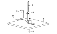
本発明は、保護管2、検知部3、導線4及び固定部材5を備えるセンサ1の発明である。先ず、本発明に係るセンサ1全体の概要について説明する。センサ1は、隔壁6によって構成された容器の内部の状態を知るために用いられる。検知部3は、容器内の特定の位置に固定され、その位置における情報を検知する。検知された情報は検知部3によって電気信号に変換され、電気信号は導線4を介して容器の外部に伝達される。これらの機能を実現するため、容器の隔壁6に形成された貫通穴61に保護管2が固定され、検知部3及び導線4は保護管2の内部に収納される。導線4は、隔壁6に固定された固定部材5により、保護管2の外部において着脱可能に固定される。 <Sensor>
The present invention is an invention of asensor 1 including a protective tube 2, a detection unit 3, a conducting wire 4, and a fixing member 5. First, an outline of the entire sensor 1 according to the present invention will be described. The sensor 1 is used to know the internal state of the container composed of the partition wall 6. The detection unit 3 is fixed at a specific position in the container and detects information at that position. The detected information is converted into an electric signal by the detection unit 3, and the electric signal is transmitted to the outside of the container via the conducting wire 4. In order to realize these functions, the protective tube 2 is fixed to the through hole 61 formed in the partition wall 6 of the container, and the detection unit 3 and the conducting wire 4 are housed inside the protective tube 2. The conducting wire 4 is detachably fixed to the outside of the protective tube 2 by a fixing member 5 fixed to the partition wall 6.
本発明は、保護管2、検知部3、導線4及び固定部材5を備えるセンサ1の発明である。先ず、本発明に係るセンサ1全体の概要について説明する。センサ1は、隔壁6によって構成された容器の内部の状態を知るために用いられる。検知部3は、容器内の特定の位置に固定され、その位置における情報を検知する。検知された情報は検知部3によって電気信号に変換され、電気信号は導線4を介して容器の外部に伝達される。これらの機能を実現するため、容器の隔壁6に形成された貫通穴61に保護管2が固定され、検知部3及び導線4は保護管2の内部に収納される。導線4は、隔壁6に固定された固定部材5により、保護管2の外部において着脱可能に固定される。 <Sensor>
The present invention is an invention of a
図1は、本発明の好ましい実施の形態の一例を示す斜視図である。図1に示されたセンサ1は、容器の内部に貯蔵された液体の液面の位置を検知する液位センサとして構成されている。ここに例示された容器は貯液タンクであり、貯液タンクの隔壁6に形成された貫通穴61に保護管2の長手方向が図の上下方向に平行になるように保護管2が固定されている。保護管2には、永久磁石を内蔵するフロート7が設けられる。フロート7は、貯液タンクの内部の液体の液面の位置に浮遊する。フロート7の位置は、液面の位置の変化に追随して、保護管2の長手方向に沿って上下に移動する。ただし、保護管2の容器の内部に位置する側の端(内端)には鍔状のストッパ21が設けられており、これによりフロート7が保護管2から抜け落ちないようになっている。なお、以下の説明においては、フロート7の下端がストッパ21に当接している状態におけるフロート7の位置が「初期位置」と称呼される場合がある。また、この例に示す容器は、内容物の漏出を防ぐことを目的として気密に構成されている。具体的には、隔壁6に形成された貫通穴61に保護管2が溶接によって不可分一体に固定されており、保護管2の内端は気密に閉じられている。
FIG. 1 is a perspective view showing an example of a preferred embodiment of the present invention. The sensor 1 shown in FIG. 1 is configured as a liquid level sensor that detects the position of the liquid level of the liquid stored inside the container. The container illustrated here is a liquid storage tank, and the protective tube 2 is fixed to a through hole 61 formed in the partition wall 6 of the liquid storage tank so that the longitudinal direction of the protective tube 2 is parallel to the vertical direction in the drawing. ing. The protective tube 2 is provided with a float 7 containing a permanent magnet. The float 7 floats at the position of the liquid level inside the liquid storage tank. The position of the float 7 moves up and down along the longitudinal direction of the protective tube 2 in accordance with the change in the position of the liquid level. However, a collar-shaped stopper 21 is provided at the end (inner end) of the protective tube 2 on the inner side of the container so that the float 7 does not fall out of the protective tube 2. In the following description, the position of the float 7 in a state where the lower end of the float 7 is in contact with the stopper 21 may be referred to as an “initial position”. Further, the container shown in this example is airtightly configured for the purpose of preventing leakage of the contents. Specifically, the protective tube 2 is inseparably and integrally fixed to the through hole 61 formed in the partition wall 6 by welding, and the inner end of the protective tube 2 is airtightly closed.
図2は、図1に例示された液位センサの部分断面図である。保護管2の内端(閉じられた下端)の近傍に位置する検知部3は、リードスイッチによって構成されている。リードスイッチの接点は、強磁性体を含む一組のリードによって構成されている。フロート7に内蔵された永久磁石71が検知部3に近づくと、永久磁石71によって形成される磁界によってリードの接点が閉じて通電状態になる。永久磁石71が検知部3から離れるとリードの弾性によって接点が開いて停電状態(非通電状態)になる。図2に示された実施例においては、液面の位置が低くフロート7が初期位置にあるときは、リードスイッチが通電状態になる。液面が上昇してフロート7が初期位置から上昇したときは、リードスイッチが停電状態になる。センサ1の使用者は、容器の外部において導線4の導通の有無を調べることによって、液面の位置がリードスイッチに対するフロート7の初期位置に対応する位置よりも高いか又は低いかを検知することができる。ただし、当業者に周知であるように、リードスイッチの通電状態と停電状態との切り替わりとフロート7の位置(即ち、液面の高さ)との対応関係は、例えばリードスイッチの接点の位置、ストッパ21の位置、フロート7の内部における永久磁石71等によって様々に変化するので、本発明センサの使用目的に応じて、これらを適宜定めることができる。
FIG. 2 is a partial cross-sectional view of the liquid level sensor illustrated in FIG. The detection unit 3 located near the inner end (closed lower end) of the protection tube 2 is composed of a reed switch. The contacts of a reed switch are composed of a set of reeds containing a ferromagnet. When the permanent magnet 71 built in the float 7 approaches the detection unit 3, the contact of the lead is closed by the magnetic field formed by the permanent magnet 71, and the state is energized. When the permanent magnet 71 is separated from the detection unit 3, the contact is opened due to the elasticity of the lead, resulting in a power failure state (non-energized state). In the embodiment shown in FIG. 2, when the liquid level is low and the float 7 is in the initial position, the reed switch is energized. When the liquid level rises and the float 7 rises from the initial position, the reed switch goes into a power failure state. The user of the sensor 1 detects whether the position of the liquid level is higher or lower than the position corresponding to the initial position of the float 7 with respect to the reed switch by examining the presence or absence of continuity of the conducting wire 4 outside the container. Can be done. However, as is well known to those skilled in the art, the correspondence between the switching between the energized state and the power failure state of the reed switch and the position of the float 7 (that is, the height of the liquid level) is, for example, the position of the contact point of the reed switch. Since the position of the stopper 21 and the permanent magnet 71 inside the float 7 change variously, these can be appropriately determined according to the purpose of use of the sensor of the present invention.
図2に例示されるように、検知部3は導線4と接続されている。導線4のうち検知部3と接続されてない方の端は、保護管2の上端(即ち、保護管2の容器の外部に向かって開いている側の端である外端)の開口部から外部に向かって突出している。導線4は、保護管2の外部において、隔壁6に固定された固定部材5に着脱可能に固定される。検知部3及び導線4の何れかが故障したときは、固定部材5による導線4の固定を解除し、導線4と、これに接続された検知部3とを保護管2から引き出し、これとは異なる他の正常な検知部3及び導線4と容易に交換することができる。また、保護管2の内部における検知部3の位置を変更したいときは、固定部材5による導線4の固定を解除し、検知部3を希望する位置に調整した後で、導線4を再び固定部材5に固定すればよい。
As illustrated in FIG. 2, the detection unit 3 is connected to the conductor wire 4. The end of the conducting wire 4 that is not connected to the detection unit 3 is from the opening of the upper end of the protective tube 2 (that is, the outer end that is the end of the protective tube 2 that is open toward the outside of the container). It protrudes toward the outside. The conductor 4 is detachably fixed to the fixing member 5 fixed to the partition wall 6 outside the protective tube 2. When either the detection unit 3 or the conductor 4 fails, the fixing member 5 releases the fixation of the conductor 4, and the conductor 4 and the detection unit 3 connected to the conductor 4 are pulled out from the protective tube 2, which is It can be easily replaced with another different normal detector 3 and conductor 4. Further, when it is desired to change the position of the detection unit 3 inside the protective tube 2, the fixing member 5 releases the fixing of the conducting wire 4, adjusts the detecting unit 3 to a desired position, and then fixes the conducting wire 4 again. It may be fixed to 5.
〈保護管〉
次に、本発明に係るセンサ1を構成する要素の各々につき、本発明を実施するための形態を説明する。保護管2は、内部に検知部3を収納することができる中空の管である。前述したように、容器の内部が高圧になる場合及び/又は人体に有害な化学物質を容器に貯蔵する場合等においては、容器全体を気密に構成して、内容物の漏出を防ぐ必要がある。また、一般に、検知部3は、後述するように精密な電子部品であるから、容器内に貯蔵された液体又はガスが検知部3に直接触れることを防止することが望ましい。このような場合、保護管2を使って容器の内部の雰囲気から遮断することが必要である。また、保護管2は、容器内の任意の位置に挿入して固定され、その位置に検知部3を保持する機能を有する。即ち、保護管2は、容器の内部における所望の位置まで検知部3を挿入するための空間を提供する部材である。更に、保護管2は、導線4を通す導管としても機能する。これらの機能を実現するために、図1及び図2に例示する保護管2は、容器の隔壁6に形成された貫通穴61に固定され、一方の端(内端)が容器の内部で閉じ、他方の端(外端)が容器の外部に向かって開く。このような構成を有する保護管2の内部は、容器の内部に位置しながらも容器の内部の雰囲気からは遮断され、容器の外部と連通している。 <Protective tube>
Next, a mode for carrying out the present invention will be described for each of the elements constituting thesensor 1 according to the present invention. The protective tube 2 is a hollow tube in which the detection unit 3 can be housed. As mentioned above, when the inside of the container becomes high pressure and / or when chemical substances harmful to the human body are stored in the container, it is necessary to make the entire container airtight to prevent leakage of the contents. .. Further, in general, since the detection unit 3 is a precision electronic component as described later, it is desirable to prevent the liquid or gas stored in the container from directly touching the detection unit 3. In such a case, it is necessary to use a protective tube 2 to block the atmosphere inside the container. Further, the protective tube 2 has a function of being inserted and fixed at an arbitrary position in the container and holding the detection unit 3 at that position. That is, the protective tube 2 is a member that provides a space for inserting the detection unit 3 to a desired position inside the container. Further, the protective tube 2 also functions as a conduit through which the conducting wire 4 passes. In order to realize these functions, the protective tube 2 illustrated in FIGS. 1 and 2 is fixed to a through hole 61 formed in the partition wall 6 of the container, and one end (inner end) is closed inside the container. , The other end (outer end) opens toward the outside of the container. Although the inside of the protective tube 2 having such a structure is located inside the container, it is shielded from the atmosphere inside the container and communicates with the outside of the container.
次に、本発明に係るセンサ1を構成する要素の各々につき、本発明を実施するための形態を説明する。保護管2は、内部に検知部3を収納することができる中空の管である。前述したように、容器の内部が高圧になる場合及び/又は人体に有害な化学物質を容器に貯蔵する場合等においては、容器全体を気密に構成して、内容物の漏出を防ぐ必要がある。また、一般に、検知部3は、後述するように精密な電子部品であるから、容器内に貯蔵された液体又はガスが検知部3に直接触れることを防止することが望ましい。このような場合、保護管2を使って容器の内部の雰囲気から遮断することが必要である。また、保護管2は、容器内の任意の位置に挿入して固定され、その位置に検知部3を保持する機能を有する。即ち、保護管2は、容器の内部における所望の位置まで検知部3を挿入するための空間を提供する部材である。更に、保護管2は、導線4を通す導管としても機能する。これらの機能を実現するために、図1及び図2に例示する保護管2は、容器の隔壁6に形成された貫通穴61に固定され、一方の端(内端)が容器の内部で閉じ、他方の端(外端)が容器の外部に向かって開く。このような構成を有する保護管2の内部は、容器の内部に位置しながらも容器の内部の雰囲気からは遮断され、容器の外部と連通している。 <Protective tube>
Next, a mode for carrying out the present invention will be described for each of the elements constituting the
保護管2は、容器内で容易に屈曲しない程度の強度を有することが好ましい。それと同時に、保護管2は、その内部に収納された検知部3が容器の内部の情報を取得する際の妨げとならないことが好ましい。例えば、センサ1を上述した液面センサとして構成する場合は、フロート7に内蔵された永久磁石71が発生する磁界がリードスイッチに到達することを妨げないように、保護管2を非磁性体で構成することが好ましい。また、センサ1を温度計として構成する場合は、保護管2の管厚をできるだけ薄くして熱容量を小さくしたり、保護管2を熱伝導性のよい材料で構成したりすることが好ましい。更に、保護管2は、容器内に貯蔵される液体又はガスと反応しにくい材料で構成されることが好ましい。保護管2に用いる材料としては、例えば、金属、合金、セラミック、合成樹脂等の材料の中から、上述した諸条件を満たす材料を選択することができる。
It is preferable that the protective tube 2 has a strength that does not easily bend in the container. At the same time, it is preferable that the protective tube 2 does not interfere with the detection unit 3 housed inside the protective tube 2 when acquiring information on the inside of the container. For example, when the sensor 1 is configured as the liquid level sensor described above, the protective tube 2 is made of a non-magnetic material so as not to prevent the magnetic field generated by the permanent magnet 71 built in the float 7 from reaching the reed switch. It is preferable to configure it. When the sensor 1 is configured as a thermometer, it is preferable that the protective tube 2 is made as thin as possible to reduce the heat capacity, or the protective tube 2 is made of a material having good thermal conductivity. Further, the protective tube 2 is preferably made of a material that does not easily react with the liquid or gas stored in the container. As the material used for the protective tube 2, for example, a material satisfying the above-mentioned conditions can be selected from materials such as metals, alloys, ceramics, and synthetic resins.
〈検知部〉
検知部3は、保護管2の内部に収納され、本発明に係るセンサ1のセンシングを担う部分である。検知部3は、保護管2の管壁を介して容器の内部に貯蔵された液体又はガスに関する情報を収集し、その情報を電気信号に変換する機能を有する。本発明における検知部3としては、温度センサ、磁気センサ、振動センサ等を用いることができるが、これらに限られない。温度センサとしては、例えば、サーミスタ、測温抵抗体及び熱電対等を用いることができる。磁気センサとしては、例えば、ホール素子及びリードスイッチ等を用いることができる。振動センサとしては、例えばマイクロフォン等を用いることができる。ここに列挙した検知部3の具体例は、何れも電気信号を発する精密な電子部品である。検知部3は、それ自体が独立して容易に交換可能なものとして構成されていることが好ましい。また、検知部3は、保護管2の内部に収納するために、太さが保護管2の内径未満のサイズである必要がある。 <Detector>
Thedetection unit 3 is housed inside the protective tube 2 and is responsible for sensing the sensor 1 according to the present invention. The detection unit 3 has a function of collecting information on the liquid or gas stored inside the container via the tube wall of the protective tube 2 and converting the information into an electric signal. As the detection unit 3 in the present invention, a temperature sensor, a magnetic sensor, a vibration sensor and the like can be used, but the detection unit 3 is not limited thereto. As the temperature sensor, for example, a thermistor, a resistance temperature detector, a thermoelectric pair, or the like can be used. As the magnetic sensor, for example, a Hall element, a reed switch, or the like can be used. As the vibration sensor, for example, a microphone or the like can be used. Specific examples of the detection unit 3 listed here are precision electronic components that emit electric signals. It is preferable that the detection unit 3 is configured to be independently and easily replaceable. Further, the detection unit 3 needs to have a thickness smaller than the inner diameter of the protective tube 2 in order to be housed inside the protective tube 2.
検知部3は、保護管2の内部に収納され、本発明に係るセンサ1のセンシングを担う部分である。検知部3は、保護管2の管壁を介して容器の内部に貯蔵された液体又はガスに関する情報を収集し、その情報を電気信号に変換する機能を有する。本発明における検知部3としては、温度センサ、磁気センサ、振動センサ等を用いることができるが、これらに限られない。温度センサとしては、例えば、サーミスタ、測温抵抗体及び熱電対等を用いることができる。磁気センサとしては、例えば、ホール素子及びリードスイッチ等を用いることができる。振動センサとしては、例えばマイクロフォン等を用いることができる。ここに列挙した検知部3の具体例は、何れも電気信号を発する精密な電子部品である。検知部3は、それ自体が独立して容易に交換可能なものとして構成されていることが好ましい。また、検知部3は、保護管2の内部に収納するために、太さが保護管2の内径未満のサイズである必要がある。 <Detector>
The
本発明において、1本の保護管2の内部に収納される検知部3の数は、1個であってもよいし、2個以上であってもよい。検知部3の数が1個であるときは、保護管2における検知部3の位置は、保護管2の内端から外端までの任意の位置に保持することができる。検知部3の数が2個以上であるときは、保護管2における個々の検知部3の位置は、例えば、上述した特許文献1に記載された上下2個のリードスイッチのように、互いに異なる位置に保持することができる。1本の保護管2の内部に複数の検知部3が収納される場合、検知部3の全て又は一部の種類が同一であってもよいし、全ての検知部3の種類が互いに異なっていてもよい。
In the present invention, the number of detection units 3 housed inside one protection tube 2 may be one or two or more. When the number of detection units 3 is 1, the position of the detection unit 3 in the protection tube 2 can be held at an arbitrary position from the inner end to the outer end of the protection tube 2. When the number of detection units 3 is two or more, the positions of the individual detection units 3 in the protective tube 2 are different from each other, for example, like the two upper and lower reed switches described in Patent Document 1 described above. Can be held in position. When a plurality of detection units 3 are housed inside one protective tube 2, all or part of the detection units 3 may be of the same type, or all the types of the detection units 3 are different from each other. You may.
〈導線〉
導線4は、容器の内部に設置された検知部3によって変換された電気信号を容器の外部に伝達する。この機能を実現するために、本発明における導線4は、一方の端が保護管2の内部で検知部3に接続され、他方の端が保護管2の開いた端(外端)から外部に向かって突出する。1個の検知部3について、通常は、2本の導線4が接続される。導線4は、端部を除き、意図しない短絡及び/又は漏電等を防止するための公知の絶縁被覆を備えることが好ましい。検知部3の中には、電気信号を取り出すための導線の他に、例えば、ヒータを加熱するための補助的な導線等を必要とするものがある。本発明センサが備える導線4は、このような補助的な導線を含んでもよい。1本の導線4は、1本の導体で構成されていてもよいし、多数の細い導体をより合わせて構成されていてもよい。導線4を構成する導体としては、低酸素銅やその他の公知の金属又は合金を用いることができる。 <Conductor>
Theconducting wire 4 transmits an electric signal converted by the detection unit 3 installed inside the container to the outside of the container. In order to realize this function, one end of the conductor 4 in the present invention is connected to the detection unit 3 inside the protective tube 2, and the other end is connected to the outside from the open end (outer end) of the protective tube 2. Protrude toward. Normally, two conductors 4 are connected to one detection unit 3. It is preferable that the conductor 4 has a known insulating coating for preventing an unintended short circuit and / or electric leakage, except for the end portion. Some of the detection units 3 require, for example, an auxiliary conductor for heating the heater, in addition to the conductor for extracting the electric signal. The conductor 4 provided in the sensor of the present invention may include such an auxiliary conductor. One conductor 4 may be composed of one conductor, or may be composed of a large number of thin conductors twisted together. As the conductor constituting the conducting wire 4, low oxygen copper or other known metal or alloy can be used.
導線4は、容器の内部に設置された検知部3によって変換された電気信号を容器の外部に伝達する。この機能を実現するために、本発明における導線4は、一方の端が保護管2の内部で検知部3に接続され、他方の端が保護管2の開いた端(外端)から外部に向かって突出する。1個の検知部3について、通常は、2本の導線4が接続される。導線4は、端部を除き、意図しない短絡及び/又は漏電等を防止するための公知の絶縁被覆を備えることが好ましい。検知部3の中には、電気信号を取り出すための導線の他に、例えば、ヒータを加熱するための補助的な導線等を必要とするものがある。本発明センサが備える導線4は、このような補助的な導線を含んでもよい。1本の導線4は、1本の導体で構成されていてもよいし、多数の細い導体をより合わせて構成されていてもよい。導線4を構成する導体としては、低酸素銅やその他の公知の金属又は合金を用いることができる。 <Conductor>
The
本発明における導線4は、上述した電気信号の伝達経路としての機能に加え、後述するように、その一部が固定部材5に固定されることによって、導線4と接続された検知部3の位置が保護管2の内部の特定の位置に保持される機能をも兼ね備えている。この機能を確実に実現するためには、導線4は、長さ方向に容易に伸び縮みしたり、或いは屈曲したりしない程度の機械的強度を有することが好ましい。機械的強度を高めるには、導体の太さを太くしたり、或いは絶縁被覆の厚さを厚くしたりすること等が有効である。ただし、導線4をあまり太くし過ぎると、導体4と接続された検知部3を保護管2の内部に収納することが困難になる。特に、1本の保護管2の内部に複数の検知部3を収納する場合は、保護管2の内部への収納を妨げない程度の大きさに導線4の太さを定めることが好ましい。
The conductor 4 in the present invention has a function as a transmission path for an electric signal described above, and as will be described later, a part of the conductor 4 is fixed to a fixing member 5 to position a detection unit 3 connected to the conductor 4. Also has a function of being held at a specific position inside the protective tube 2. In order to surely realize this function, it is preferable that the conductor 4 has a mechanical strength that does not easily expand or contract in the length direction or bend. In order to increase the mechanical strength, it is effective to increase the thickness of the conductor or the thickness of the insulating coating. However, if the conductor 4 is made too thick, it becomes difficult to house the detection unit 3 connected to the conductor 4 inside the protective tube 2. In particular, when a plurality of detection units 3 are housed inside one protective tube 2, it is preferable to set the thickness of the conductor 4 to a size that does not interfere with the storage of the protective tube 2 inside.
本発明における導線4は、後述する固定部材5に固定される部分における塑性変形が容易で、固定部材5による固定と解除との繰り返しに耐え得る耐久性を有することが好ましい。塑性変形が容易であれば、固定部材5による固定がより強固なものとなり、センサ1を使用している途中で検知部3の位置がずれることを防止することができる。また、導線4の耐久性が高まれば、同一の検知部3及び導線4を用いて検知部3の位置を繰り返し調整しながら使用することができる。一方、導線4の固定部材5に固定される部分は、適度な弾性率にて弾性変形が可能であり且つ固定部材5による固定と解除との繰り返しに耐え得る耐久性を有していてもよい。この場合もまた、センサ1の使用中における検知部3のずれを防止すること及び同一の検知部3及び導線4を用いる検知部3の位置を繰り返し調整することが容易となる。
It is preferable that the conductor 4 in the present invention is easily plastically deformed at a portion fixed to the fixing member 5 described later, and has durability that can withstand repeated fixing and releasing by the fixing member 5. If the plastic deformation is easy, the fixing by the fixing member 5 becomes stronger, and it is possible to prevent the position of the detection unit 3 from being displaced while the sensor 1 is being used. Further, if the durability of the conductor 4 is increased, the same detection unit 3 and the conductor 4 can be used while repeatedly adjusting the position of the detection unit 3. On the other hand, the portion of the conducting wire 4 fixed to the fixing member 5 may be elastically deformed with an appropriate elastic modulus and has durability capable of withstanding repeated fixing and releasing by the fixing member 5. .. Also in this case, it becomes easy to prevent the detection unit 3 from being displaced during the use of the sensor 1 and to repeatedly adjust the positions of the detection unit 3 and the detection unit 3 using the same conductor 4.
検知部3が熱電対であり、導線4が2種類の貴金属線によって構成され、検知部3がこれらの貴金属同士の溶接部によって構成される場合がある。貴金属によって構成された導線4は固定部材5による固定と解除との繰り返しに耐えられないおそれがある。このような場合は、貴金属線よりも高い耐久性を有する補償導線と貴金属線とを接続して導線4を構成し、補償導線の部分を固定部材5に固定するようにすることが好ましい。また、先端が溶接された2種類の貴金属線をシースと呼ばれる金属保護管の内部に密封するタイプの熱電対が知られている。この場合、溶接された先端部が本発明の検知部3に相当し、シースで覆われた貴金属線の部分が本発明の導線4に該当することになる。
In some cases, the detection unit 3 is a thermocouple, the conducting wire 4 is composed of two types of precious metal wires, and the detection unit 3 is composed of welded portions of these precious metals. The conductor 4 made of precious metal may not be able to withstand repeated fixing and releasing by the fixing member 5. In such a case, it is preferable to connect the compensating conductor and the noble metal wire, which have higher durability than the noble metal wire, to form the conducting wire 4, and fix the portion of the compensating conducting wire to the fixing member 5. Further, there is known a type of thermocouple in which two types of precious metal wires having welded tips are sealed inside a metal protective tube called a sheath. In this case, the welded tip portion corresponds to the detection portion 3 of the present invention, and the portion of the precious metal wire covered with the sheath corresponds to the conductor wire 4 of the present invention.
〈固定部材〉
固定部材5は、導線4を所定の位置に固定する部材である。固定部材5は、容器の隔壁6に固定されている。保護管2も、同じ隔壁6に形成された貫通穴61に固定されている。従って、導線4を固定部材5に固定することによって、導線4全体が保護管2の内部において保護管2の軸の方向(長手方向)に移動することが妨げられる。導線4全体の位置が固定されると、導線4に接続され保護管2の内部に収納された1個又は2個以上の検知部3の位置が特定の位置に保持される。このようにして検知部3が所定の位置に保持されると、センサ1が検知部3を用いて容器内の特定の位置においてセンシングを実行することが可能となる。固定部材5による導線4の固定は、保護管2の外部において行われる。より具体的には、導線4の端が保護管2の開いた端(外端)から保護管2の外部に向かって突出しているので、その突出している部分を固定部材5に固定する。固定部材5による導線4の固定及び/又は解除は、保護管2の内部においてではなく、保護管2の外部の広い空間において実行されるので、固定及び/又は解除の作業を容易に行うことができる。 <Fixing member>
The fixingmember 5 is a member that fixes the conducting wire 4 at a predetermined position. The fixing member 5 is fixed to the partition wall 6 of the container. The protective tube 2 is also fixed to the through hole 61 formed in the same partition wall 6. Therefore, by fixing the conductor 4 to the fixing member 5, it is prevented that the entire conductor 4 moves in the axial direction (longitudinal direction) of the protective tube 2 inside the protective tube 2. When the position of the entire conductor 4 is fixed, the positions of one or more detection units 3 connected to the conductor 4 and housed inside the protective tube 2 are held at a specific position. When the detection unit 3 is held at a predetermined position in this way, the sensor 1 can perform sensing at a specific position in the container using the detection unit 3. The fixing of the conducting wire 4 by the fixing member 5 is performed outside the protective tube 2. More specifically, since the end of the conducting wire 4 projects from the open end (outer end) of the protective tube 2 toward the outside of the protective tube 2, the protruding portion is fixed to the fixing member 5. Since the fixing and / or release of the conducting wire 4 by the fixing member 5 is performed not inside the protection tube 2 but in a wide space outside the protection tube 2, the fixing and / or release work can be easily performed. can.
固定部材5は、導線4を所定の位置に固定する部材である。固定部材5は、容器の隔壁6に固定されている。保護管2も、同じ隔壁6に形成された貫通穴61に固定されている。従って、導線4を固定部材5に固定することによって、導線4全体が保護管2の内部において保護管2の軸の方向(長手方向)に移動することが妨げられる。導線4全体の位置が固定されると、導線4に接続され保護管2の内部に収納された1個又は2個以上の検知部3の位置が特定の位置に保持される。このようにして検知部3が所定の位置に保持されると、センサ1が検知部3を用いて容器内の特定の位置においてセンシングを実行することが可能となる。固定部材5による導線4の固定は、保護管2の外部において行われる。より具体的には、導線4の端が保護管2の開いた端(外端)から保護管2の外部に向かって突出しているので、その突出している部分を固定部材5に固定する。固定部材5による導線4の固定及び/又は解除は、保護管2の内部においてではなく、保護管2の外部の広い空間において実行されるので、固定及び/又は解除の作業を容易に行うことができる。 <Fixing member>
The fixing
本発明において、固定部材5は、導線4を着脱可能に固定する。ここで「着脱可能に固定する」とは、固定部材5に一度固定された導線4を、破壊することなく再び固定部材5から分離できることを意味する。保護管2の内部に収納された検知部3の位置を変更したい場合は、先ず、固定部材5への導線4の固定を解除し、次に、固定部材5に固定される導線4の位置を変更してから再び固定部材5に固定すればよい。本発明においては、導線4が固定部材5に着脱可能に固定されているので、上述する検知部3の位置調整の作業は、導線4及び固定部材5を破壊すること無く何度でも繰り返し実行することができる。
In the present invention, the fixing member 5 fixes the conducting wire 4 in a detachable manner. Here, "fixing detachably" means that the conducting wire 4 once fixed to the fixing member 5 can be separated from the fixing member 5 again without breaking. When it is desired to change the position of the detection unit 3 housed inside the protective tube 2, first release the fixing of the conducting wire 4 to the fixing member 5, and then change the position of the conducting wire 4 fixed to the fixing member 5. After changing, it may be fixed to the fixing member 5 again. In the present invention, since the conductor 4 is detachably fixed to the fixing member 5, the above-mentioned work of adjusting the position of the detection unit 3 is repeatedly executed as many times as necessary without damaging the conductor 4 and the fixing member 5. be able to.
また、検知部3及び/又は導線4が故障して、これらの一方又は双方を交換したい場合には、先ず、固定部材5への導線4の固定を解除して保護管2から検知部3及び導線4を取り出し、次に、新しい検知部3及び/又は導線4を保護管2の内部に収納し、検知部3の位置を調整してから、保護管2の外部において導線4を固定部材5に固定すればよい。本発明においては、導線4が固定部材5に着脱可能に固定されているので、上述する検知部3及び/又は導線4の交換作業を極めて容易に実行することができる。
If the detection unit 3 and / or the conductor 4 fails and one or both of them are to be replaced, first, the wire 4 is released from the fixing member 5 and the protective tube 2 is used to replace the detection unit 3 and / or the conductor 4. The conductor 4 is taken out, then the new detection unit 3 and / or the conductor 4 is housed inside the protective tube 2, the position of the detection unit 3 is adjusted, and then the conductor 4 is fixed to the fixing member 5 outside the protective tube 2. It should be fixed to. In the present invention, since the conductor 4 is detachably fixed to the fixing member 5, the above-mentioned replacement work of the detection unit 3 and / or the conductor 4 can be performed extremely easily.
本発明において、固定部材5の構造は、導線4を着脱可能に固定できる構造であれば、どのような構造であってもよい。図3は、本発明の好ましい実施の形態に係る固定部材5の部分を拡大した斜視図である。本発明の好ましい実施の形態において、固定部材5は、隔壁6に固定された本体51と、本体51に接合することができる固定片52とを備える。導線4は、本体51と固定片52との間に挟まれて固定される。この好ましい実施の形態において、導線4は、本体51と固定片52との間に挟まれて、両者から圧縮応力を受けている。導線4の表面と、本体51と固定片52のそれぞれの表面との間には、圧縮応力に起因する静的摩擦力が生じるので、導線4は固定部材5に固定され、その位置を容易に移動することができない。
In the present invention, the structure of the fixing member 5 may be any structure as long as the conducting wire 4 can be detachably fixed. FIG. 3 is an enlarged perspective view of a portion of the fixing member 5 according to the preferred embodiment of the present invention. In a preferred embodiment of the present invention, the fixing member 5 includes a main body 51 fixed to the partition wall 6 and a fixing piece 52 that can be joined to the main body 51. The conducting wire 4 is sandwiched and fixed between the main body 51 and the fixing piece 52. In this preferred embodiment, the conductor 4 is sandwiched between the main body 51 and the fixing piece 52 and receives compressive stress from both. Since a static frictional force due to compressive stress is generated between the surface of the conducting wire 4 and the surfaces of the main body 51 and the fixing piece 52, the conducting wire 4 is fixed to the fixing member 5 and its position can be easily positioned. I can't move.
本発明の好ましい実施の形態において、本体51の隔壁6への固定は、例えばネジ止め等によって着脱可能に固定してもよいし、或いは、例えば溶接等によって固定してもよい。仮に、本体51と隔壁6との間の固定が溶接等の堅固なものであったとしても、本体51と固定片52による導線4の固定が着脱可能なものであれば、本発明による効果を得ることができる。図3に例示する固定部材5において、本体51と固定片52は、本体51に設けられた穴に挿入された2個の雄ネジと固定片52に設けられた2個所のネジ穴とによって締結可能に構成されている。本体51と固定片52との間に導線4が挟まれた状態において雄ネジをネジ穴に螺合させることによって、導線4を固定部材5に着脱可能に固定することができる。
In a preferred embodiment of the present invention, the main body 51 may be detachably fixed to the partition wall 6 by, for example, screwing, or may be fixed by welding, for example. Even if the fixing between the main body 51 and the partition wall 6 is solid such as welding, if the fixing of the conducting wire 4 by the main body 51 and the fixing piece 52 is removable, the effect according to the present invention can be obtained. Obtainable. In the fixing member 5 illustrated in FIG. 3, the main body 51 and the fixing piece 52 are fastened by two male screws inserted into the holes provided in the main body 51 and two screw holes provided in the fixing piece 52. It is configured to be possible. The conductor 4 can be detachably fixed to the fixing member 5 by screwing the male screw into the screw hole while the conductor 4 is sandwiched between the main body 51 and the fixing piece 52.
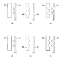
ところで、本体51と固定片52との間に導線4を挟んで導線4をより確実且つ強固に保持する観点からは、導線4を挟む本体51の面及び固定片52の面の何れか一方又は両方に凹凸が形成されていることが好ましい。図4は、このように導線4を挟む本体51の面及び固定片52の面の何れか一方又は両方に凹凸が形成されている実施の形態を例示する模式図である。ただし、図4においては、導線4は省略されている。図4の(a)、(b)、(d)及び(e)に示すように、導線4を挟む本体51の面及び固定片52の面の何れか一方のみに凹凸が形成されていてもよい。或いは、図4の(c)及び(f)に示すように、導線4を挟む本体51の面及び固定片52の面の両方に凹凸が形成されていてもよい。また、図4に示した例においては、導線4を挟む本体51の面及び固定片52の面の何れか一方又は両方に複数の凹凸が形成されているが、導線4を固定部材5に着脱可能に固定することが可能である限り凹凸の数は限定されず、例えば凹部及び/又は凸部が1つだけ形成されていてもよい。
By the way, from the viewpoint of sandwiching the conducting wire 4 between the main body 51 and the fixing piece 52 and holding the conducting wire 4 more reliably and firmly, either one of the surfaces of the main body 51 and the surface of the fixing piece 52 sandwiching the conducting wire 4 or It is preferable that unevenness is formed on both sides. FIG. 4 is a schematic view illustrating an embodiment in which irregularities are formed on either or both of the surface of the main body 51 and the surface of the fixing piece 52 that sandwich the conductor 4 in this way. However, in FIG. 4, the conductor 4 is omitted. As shown in (a), (b), (d) and (e) of FIG. 4, even if unevenness is formed on only one of the surface of the main body 51 and the surface of the fixed piece 52 sandwiching the conducting wire 4. good. Alternatively, as shown in FIGS. 4 (c) and 4 (f), irregularities may be formed on both the surface of the main body 51 and the surface of the fixing piece 52 sandwiching the conducting wire 4. Further, in the example shown in FIG. 4, a plurality of irregularities are formed on either or both of the surface of the main body 51 and the surface of the fixing piece 52 sandwiching the conducting wire 4, but the conducting wire 4 is attached to and detached from the fixing member 5. The number of irregularities is not limited as long as it can be fixed as possible, and for example, only one concave portion and / or convex portion may be formed.
次に、図5の(a)を参照すると、本発明のより好ましい実施の形態において、本体51又は固定片52のうちの何れか一方は、固定穴53を備え、本体51又は固定片52のうちの他方は、固定穴53の位置に対応する位置に凸部54を備え、固定片52を本体51に接合することによって、導線4が凸部54によって固定穴53の方向に押し出されて固定される。図5の(a)は、導線4が固定部材5に固定される前の状態を表している。図5の(a)に示された本発明の実施の形態において、固定穴53は本体51の最も大きな面の中央部に設けられている。また、凸部54は、固定穴52に対応する位置である固定片52の中央部に設けられている。図5の(a)に示す状態から、2個のネジを締め付けて固定片52を本体51に接合することにより、導線4が凸部54によって固定穴53の方向に押し出されて着脱可能に固定される。
Next, referring to (a) of FIG. 5, in a more preferable embodiment of the present invention, either one of the main body 51 or the fixed piece 52 is provided with a fixing hole 53, and the main body 51 or the fixed piece 52 is provided with a fixing hole 53. The other of them is provided with a convex portion 54 at a position corresponding to the position of the fixing hole 53, and by joining the fixing piece 52 to the main body 51, the conducting wire 4 is pushed out in the direction of the fixing hole 53 by the convex portion 54 and fixed. Will be done. FIG. 5A shows a state before the conductor 4 is fixed to the fixing member 5. In the embodiment of the present invention shown in FIG. 5A, the fixing hole 53 is provided at the center of the largest surface of the main body 51. Further, the convex portion 54 is provided at the central portion of the fixing piece 52, which is a position corresponding to the fixing hole 52. From the state shown in FIG. 5A, by tightening two screws to join the fixing piece 52 to the main body 51, the conducting wire 4 is pushed out in the direction of the fixing hole 53 by the convex portion 54 and fixed detachably. Will be done.
図1及び図2は、固定部材5によって導線4が固定された最終状態を表している。この最終状態において、導線4は、凸部54によって固定穴53の方向に押し出されて変形している。この状態から導線4を図の上下方向に移動させるためには、導線4に新たな変形を起こさせる必要がある。このため、図1及び図2に示された本発明の実施の形態においては、上述した静止摩擦力のみによって導線4を固定した場合と比較して、導線4をより強固に固定することができる。なお、上述した実施の形態においては、固定穴53は本体51に、凸部54は固定片52にそれぞれ設けられているが、これとは逆に、固定穴53を固定片52に、凸部54を本体51に設けた場合であっても、上述した実施の形態と全く同じように強固な固定を行うことができる。
1 and 2 show the final state in which the conducting wire 4 is fixed by the fixing member 5. In this final state, the conducting wire 4 is pushed out in the direction of the fixing hole 53 by the convex portion 54 and deformed. In order to move the conductor 4 in the vertical direction shown in the figure from this state, it is necessary to cause the conductor 4 to undergo a new deformation. Therefore, in the embodiment of the present invention shown in FIGS. 1 and 2, the conductor 4 can be fixed more firmly than in the case where the conductor 4 is fixed only by the above-mentioned static frictional force. .. In the above-described embodiment, the fixing hole 53 is provided in the main body 51 and the convex portion 54 is provided in the fixing piece 52. On the contrary, the fixing hole 53 is provided in the fixing piece 52 and the convex portion 52. Even when the 54 is provided on the main body 51, it can be firmly fixed in exactly the same manner as in the above-described embodiment.
図5の(a)に例示した固定部材5において、本体51は、例えば、折り曲げた金属板等によって構成することができる。また、固定片52は、例えば、溝及びネジ穴を設けた金属又は合金のブロック等によって構成することができる。図5の(a)に例示された固定片52において、図の上下方向に平行に設けられた溝55は、導線4を収納する逃げ溝である。凸部54の高さは、ネジ穴が設けられている面と同じ高さになっている。これにより、固定片52が本体51に接合されたときに、凸部54が導線4を固定穴53の方向に確実に押し出すことができる。
In the fixing member 5 illustrated in FIG. 5A, the main body 51 can be formed of, for example, a bent metal plate or the like. Further, the fixing piece 52 can be formed of, for example, a metal or alloy block provided with a groove and a screw hole. In the fixing piece 52 illustrated in FIG. 5A, the groove 55 provided in parallel in the vertical direction in the drawing is an escape groove for accommodating the conducting wire 4. The height of the convex portion 54 is the same as the height of the surface on which the screw hole is provided. As a result, when the fixing piece 52 is joined to the main body 51, the convex portion 54 can surely push out the conducting wire 4 in the direction of the fixing hole 53.
ところで、上述したように固定穴53の方向に導線4を押し出すと共に導線4を収納するためには、例えば図5の(b)に示すように、凸部54及び逃げ溝55のみを固定片52に形成すれば十分な筈である。図5の(b)に示すような固定片52は、例えば射出成形等の樹脂成形によって容易に製作することができる。しかしながら、例えばフライス加工等の切削加工により金属片(例えば、アルミニウム片等)に逃げ溝55を形成するのみでは、逃げ溝55の終端(凸部54側の端部)を図5の(b)に例示したように加工することは困難である。そこで、図5の(a)に例示した固定片52においては、導線4を収納する逃げ溝と直交するように形成された2本の溝が凸部54の上下に形成されているのである。ただし、本体51及び固定片52の構成は、上述した構成に限られるものではなく、本体51と固定片52との間に導線4を挟んで固定することが可能である限り、特に限定されない。
By the way, in order to push out the conductor 4 in the direction of the fixing hole 53 and store the conductor 4 as described above, for example, as shown in FIG. 5B, only the convex portion 54 and the relief groove 55 are fixed to the fixing piece 52. It should be enough if it is formed in. The fixed piece 52 as shown in FIG. 5B can be easily manufactured by resin molding such as injection molding. However, if only the relief groove 55 is formed in the metal piece (for example, an aluminum piece) by cutting such as milling, the end of the relief groove 55 (the end on the convex portion 54 side) is formed in FIG. 5 (b). It is difficult to process as illustrated in. Therefore, in the fixed piece 52 illustrated in FIG. 5A, two grooves formed so as to be orthogonal to the relief groove for accommodating the conducting wire 4 are formed above and below the convex portion 54. However, the configurations of the main body 51 and the fixing piece 52 are not limited to the above-mentioned configurations, and are not particularly limited as long as the conductor 4 can be sandwiched between the main body 51 and the fixing piece 52 and fixed.
〈容器〉
本発明に係るセンサ1の構成は容器を含まないが、センサ1は容器の隔壁6に固定して使用することを前提として構成されている。本発明に係るセンサ1を固定する容器とは、外部と内部とを隔てる隔壁6を備える容れ物であれば、どのような容器であってもよい。例えば、液体又はガスを貯蔵するタンクや、熱処理炉又は反応炉の炉室等は、本発明における容器に該当し得る。本発明に係るセンサ1を構成する保護管2は、容器の隔壁6に形成された貫通穴61に固定される。容器を構成する隔壁6のうち貫通穴61を設ける位置は、その容器のうちセンサ1によって内部の情報を検知したい位置にできるだけ近い位置に設けることが好ましい。図1乃至図3及び図5に示された隔壁6は、容器を構成する隔壁6のうち保護管2及び固定部材5が固定されている部分のみを切り取って示したものである。隔壁6の形状は四角形で示されているが、この形状に特段の意味はない。これらの図において、保護管2が固定されている側が容器の内部に相当し、固定部材5が固定されている側が容器の外部に相当する。ただし、保護管2の容器の外部に向かって開いている側の端(外端)は必ずしも隔壁6と面一である必要は無く、隔壁6から突出していてもよい。また、センサ1が適用される容器の用途において許容される限りにおいて、必ずしも固定部材5の全体が容器の外側に位置する必要は無い。即ち、固定部材5の構成は、隔壁6に固定され且つ保護管2の外部において導線4を着脱可能に固定することが可能である限り、特に限定されない。 <container>
The configuration of thesensor 1 according to the present invention does not include the container, but the sensor 1 is configured on the premise that it is used by being fixed to the partition wall 6 of the container. The container for fixing the sensor 1 according to the present invention may be any container as long as it is a container having a partition wall 6 that separates the outside from the inside. For example, a tank for storing liquid or gas, a furnace chamber of a heat treatment furnace or a reaction furnace, and the like can correspond to the container in the present invention. The protective tube 2 constituting the sensor 1 according to the present invention is fixed to a through hole 61 formed in the partition wall 6 of the container. It is preferable that the position of the through hole 61 in the partition wall 6 constituting the container is provided as close as possible to the position in the container where the internal information is to be detected by the sensor 1. The partition wall 6 shown in FIGS. 1 to 3 and 5 is obtained by cutting out only a portion of the partition wall 6 constituting the container to which the protective tube 2 and the fixing member 5 are fixed. The shape of the partition wall 6 is shown as a quadrangle, but this shape has no particular meaning. In these figures, the side on which the protective tube 2 is fixed corresponds to the inside of the container, and the side on which the fixing member 5 is fixed corresponds to the outside of the container. However, the end (outer end) of the protective tube 2 that is open toward the outside of the container does not necessarily have to be flush with the partition wall 6, and may protrude from the partition wall 6. Further, as long as the application of the container to which the sensor 1 is applied allows, the entire fixing member 5 does not necessarily have to be located outside the container. That is, the configuration of the fixing member 5 is not particularly limited as long as it is fixed to the partition wall 6 and the conducting wire 4 can be detachably fixed outside the protective tube 2.
本発明に係るセンサ1の構成は容器を含まないが、センサ1は容器の隔壁6に固定して使用することを前提として構成されている。本発明に係るセンサ1を固定する容器とは、外部と内部とを隔てる隔壁6を備える容れ物であれば、どのような容器であってもよい。例えば、液体又はガスを貯蔵するタンクや、熱処理炉又は反応炉の炉室等は、本発明における容器に該当し得る。本発明に係るセンサ1を構成する保護管2は、容器の隔壁6に形成された貫通穴61に固定される。容器を構成する隔壁6のうち貫通穴61を設ける位置は、その容器のうちセンサ1によって内部の情報を検知したい位置にできるだけ近い位置に設けることが好ましい。図1乃至図3及び図5に示された隔壁6は、容器を構成する隔壁6のうち保護管2及び固定部材5が固定されている部分のみを切り取って示したものである。隔壁6の形状は四角形で示されているが、この形状に特段の意味はない。これらの図において、保護管2が固定されている側が容器の内部に相当し、固定部材5が固定されている側が容器の外部に相当する。ただし、保護管2の容器の外部に向かって開いている側の端(外端)は必ずしも隔壁6と面一である必要は無く、隔壁6から突出していてもよい。また、センサ1が適用される容器の用途において許容される限りにおいて、必ずしも固定部材5の全体が容器の外側に位置する必要は無い。即ち、固定部材5の構成は、隔壁6に固定され且つ保護管2の外部において導線4を着脱可能に固定することが可能である限り、特に限定されない。 <container>
The configuration of the
本発明の好ましい実施の形態において、容器は、気密容器であり、保護管2は、隔壁6と不可分一体に固定される。上述したように、容器の内部が高圧になる場合及び/又は人体に有害な化学物質を容器に貯蔵する場合等においては、容器全体を隙間無く気密に構成して、内容物の漏出を防ぐことが好ましい。この目的のためには、容器の隔壁6に形成された貫通穴61とセンサ1の保護管2とを不可分一体に構成することが有効である。具体的には、例えば、金属又は合金からなる容器の隔壁6と保護管2とを溶接したり、熱可塑性樹脂からなる容器の隔壁6と保護管2とを溶着したりすること等が考えられる。また、この場合、保護管2の容器の内部に位置する側の端(内端)は、気密に閉じられている。
In a preferred embodiment of the present invention, the container is an airtight container, and the protective tube 2 is inseparably fixed to the partition wall 6. As described above, when the inside of the container becomes high pressure and / or when chemical substances harmful to the human body are stored in the container, the entire container should be airtightly constructed without any gaps to prevent leakage of the contents. Is preferable. For this purpose, it is effective to integrally configure the through hole 61 formed in the partition wall 6 of the container and the protective tube 2 of the sensor 1 inseparably. Specifically, for example, it is conceivable to weld the partition wall 6 of the container made of metal or alloy and the protective tube 2, or to weld the partition wall 6 of the container made of thermoplastic resin and the protective tube 2. .. Further, in this case, the end (inner end) of the protective tube 2 located inside the container is airtightly closed.
ところで、上述したように検知部3及び/又は導線4を交換したり検知部3の位置調整をしたりする際に導線4を固定部材5によって固定して検知部3を保護管2の内部における所望の位置に保持するための手法は特に限定されない。例えば、固定部材5における固定箇所と検知部3のセンシング部位が保持されるべき箇所との間の距離に応じて固定部材5によって導線4が固定されるべき箇所を予め特定しておき、当該箇所において固定部材5によって導線4を固定してもよい。或いは、例えば、保護管2の容器の内部に位置する側の端(内端)が閉じられている場合は、保護管2の内端に当接するまで保護管2の内部において検知部3を下降させることにより、保護管2の内端の位置に対応する位置に検知部3を確実に保持することができる。
By the way, as described above, when the detection unit 3 and / or the conductor 4 is replaced or the position of the detection unit 3 is adjusted, the conductor 4 is fixed by the fixing member 5 and the detection unit 3 is inside the protective tube 2. The method for holding in a desired position is not particularly limited. For example, a location where the conducting wire 4 should be fixed by the fixing member 5 is specified in advance according to the distance between the fixing portion of the fixing member 5 and the portion where the sensing portion of the detection unit 3 should be held. In, the conducting wire 4 may be fixed by the fixing member 5. Alternatively, for example, when the end (inner end) of the protective tube 2 located inside the container is closed, the detection unit 3 is lowered inside the protective tube 2 until it comes into contact with the inner end of the protective tube 2. By doing so, the detection unit 3 can be reliably held at a position corresponding to the position of the inner end of the protection tube 2.
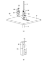
上記のような手法により保護管2の内端と容器の外部に向かって開いている側の端(外端)との間の所定の位置に検知部3を保持する場合は、検知部3の先端(即ち、保護管2の内端側の端)にスペーサを設けてもよい。図6は、本発明のこのような実施の形態に係るセンサ1の部分断面図である。図6に例示するセンサ1は、フロート7の下限位置を規定するストッパ21に加えてフロート7の上限位置を規定するストッパ22を更に備える点及び保護管2の内部において検知部3の先端側(内端側)に配設されたスペーサ31を更に備える点を除き、図2に例示したセンサ1と同様の構成を有する。
When the detection unit 3 is held at a predetermined position between the inner end of the protective tube 2 and the end (outer end) on the side open toward the outside of the container by the above method, the detection unit 3 A spacer may be provided at the tip (that is, the end on the inner end side of the protective tube 2). FIG. 6 is a partial cross-sectional view of the sensor 1 according to such an embodiment of the present invention. The sensor 1 illustrated in FIG. 6 further includes a stopper 22 that defines the upper limit position of the float 7 in addition to the stopper 21 that defines the lower limit position of the float 7, and the tip side of the detection unit 3 inside the protection tube 2 ( It has the same configuration as the sensor 1 illustrated in FIG. 2, except that the spacer 31 is further provided on the inner end side).
図6に例示するセンサ1においては、上記のように、スペーサ31が保護管2の内部において検知部3の内端(保護管2の容器の内部に位置する側の端)の側に配設されている。従って、所定の長さを有するスペーサ31が保護管2の内端に当接するまで保護管2の内部において検知部3を下降させることにより、所望の位置に検知部3を確実に保持することができる。保護管2の内部における検知部3の位置を変更する場合は、スペーサ31の長さを変更すればよい。
In the sensor 1 illustrated in FIG. 6, as described above, the spacer 31 is arranged inside the protective tube 2 on the side of the inner end of the detection unit 3 (the end on the side of the protective tube 2 located inside the container). Has been done. Therefore, the detection unit 3 can be reliably held at a desired position by lowering the detection unit 3 inside the protection tube 2 until the spacer 31 having a predetermined length abuts on the inner end of the protection tube 2. can. When changing the position of the detection unit 3 inside the protection tube 2, the length of the spacer 31 may be changed.
ここで、隔壁6と不可分一体に固定された保護管2に検知部3及び導線4を設けてセンサを構成しようとする場合に、本発明と従来技術との間に如何なる違いがあるかについて、図を用いて説明する。この比較説明において、保護管2は、隔壁6と不可分一体に固定されている。図7は、従来技術に係るセンサ1’を示す斜視図である。図7に例示される従来技術に係るセンサ1’は、図1に示された本発明の好ましい実施の形態に係るセンサ1と同様に、容器の内部に貯蔵された液体の液面の位置を検知する液位センサとして構成されている。図7に示されたセンサ1’の構成のうち、保護管2、導線4、隔壁6及びフロート7並びに図に示されていない検知部3の構成は、図1及び図2に示されたセンサ1と同じであるから、ここでは同一の記号を用いて説明を省略する。センサ1’とセンサ1との構成における唯一の違いは、センサ1’はセンサ1が備える固定部材5を欠く点である。
Here, what kind of difference is there between the present invention and the prior art when the detection unit 3 and the conducting wire 4 are provided on the protective tube 2 inseparably fixed to the partition wall 6 to form a sensor? This will be described with reference to the figures. In this comparative explanation, the protective tube 2 is inseparably fixed to the partition wall 6. FIG. 7 is a perspective view showing the sensor 1'according to the prior art. The sensor 1'according to the prior art exemplified in FIG. 7 determines the position of the liquid level of the liquid stored inside the container, similarly to the sensor 1 according to the preferred embodiment of the present invention shown in FIG. It is configured as a liquid level sensor to detect. Among the configurations of the sensor 1'shown in FIG. 7, the configurations of the protective tube 2, the conducting wire 4, the partition wall 6 and the float 7, and the detection unit 3 not shown in the figure are the sensors shown in FIGS. 1 and 2. Since it is the same as 1, the same symbol is used here and the description thereof will be omitted. The only difference in the configuration of the sensor 1'and the sensor 1 is that the sensor 1'lacks the fixing member 5 included in the sensor 1.
図7に示された従来技術に係るセンサ1’においては、保護管2の内部に検知部3及び導線4を固定する手段として、例えば、図示しない接着剤を用いることができる。接着剤は、例えば、保護管2の上端(外端)において、保護管2の内部で、導線4を保護管2の内壁の表面に固定することを目的として使用することができる。この目的のために使用される接着剤として、例えば、二液混合型のエポキシ系樹脂接着剤を用いる場合は、接着剤が硬化する際の体積変化が少ないので、導線4を保護管2に強固に固定することができる。しかしながら、硬化後の接着剤は非常に硬いので、例えば検知部3及び導線4を交換する等の目的のために導線4を保護管2から引き剥がそうとしても、導線4を破壊すること無くこれを行うことは殆ど不可能である。一方、上述したエポキシ系樹脂接着剤よりも軟らかいシリコンシーラント等を接着剤として用いることもできる。しかし、この場合も、保護管2の内部に導線4が接着されているため、狭い空間に充填された接着剤を取り除いて導線4を取り出すのは容易ではない。
In the sensor 1'according to the prior art shown in FIG. 7, for example, an adhesive (not shown) can be used as a means for fixing the detection unit 3 and the conducting wire 4 inside the protective tube 2. The adhesive can be used, for example, at the upper end (outer end) of the protective tube 2 for the purpose of fixing the conducting wire 4 to the surface of the inner wall of the protective tube 2 inside the protective tube 2. When, for example, a two-component mixed type epoxy resin adhesive is used as the adhesive used for this purpose, the volume change when the adhesive is cured is small, so that the lead wire 4 is firmly attached to the protective tube 2. Can be fixed to. However, since the adhesive after curing is very hard, even if the conductor 4 is to be peeled off from the protective tube 2 for the purpose of exchanging the detection unit 3 and the conductor 4, the conductor 4 is not destroyed. Is almost impossible to do. On the other hand, a silicone sealant or the like, which is softer than the above-mentioned epoxy resin adhesive, can also be used as the adhesive. However, also in this case, since the conducting wire 4 is adhered to the inside of the protective tube 2, it is not easy to remove the adhesive filled in the narrow space and take out the conducting wire 4.
そこで、例えば、接着剤の使用量を低減する等して保護管2の上端(外端)における導線4の保護管2への接着をあまり強固なものにせず、保護管2から導線4を容易に取り外せるようにすることが考えられる。しかし、この場合は、検知部3の大きさ及び/又は重量によっては、検知部3が保護管2の内部で動いたり、検知部3の位置が定まらなかったりするおそれがある。これを防ぐために検知部3と保護管2とを接着した場合は、導線4を引っ張って検知部3を保護管2から引き出そうとする際に、検知部3が保護管2の内部から外れず検知部3を保護管2から引き出せなかったり、導線4を無理に引っ張って導線4と検知部3との接続が外れてしまったりするおそれがある。このように、保護管2が容器の隔壁6に不可分一体に固定されている場合、従来技術に係るセンサ1’においては、検知部3及び導線4を交換したり、保護管2における検知部3の収納位置を事後的に調整したりすることが極めて困難であった。なお、このような事情は、上記において例示した液位センサに限らず、例えば温度センサ、磁気センサ及び振動センサ等の他のセンサにおいても同様である。
Therefore, for example, by reducing the amount of adhesive used, the adhesion of the conducting wire 4 to the protective tube 2 at the upper end (outer end) of the protective tube 2 is not made so strong, and the conducting wire 4 can be easily made from the protective tube 2. It is conceivable that it can be removed. However, in this case, depending on the size and / or weight of the detection unit 3, the detection unit 3 may move inside the protective tube 2 or the position of the detection unit 3 may not be determined. When the detection unit 3 and the protection tube 2 are adhered to prevent this, when the detection unit 3 is pulled out from the protection tube 2 by pulling the lead wire 4, the detection unit 3 does not come off from the inside of the protection tube 2 and detects it. There is a risk that the unit 3 cannot be pulled out from the protective tube 2 or that the conductor 4 is forcibly pulled to disconnect the conductor 4 from the detection unit 3. In this way, when the protective tube 2 is inseparably and integrally fixed to the partition wall 6 of the container, in the sensor 1'according to the prior art, the detection unit 3 and the conducting wire 4 can be replaced, or the detection unit 3 in the protective tube 2 can be replaced. It was extremely difficult to adjust the storage position of the device after the fact. It should be noted that such a situation is not limited to the liquid level sensor exemplified above, but is the same for other sensors such as a temperature sensor, a magnetic sensor and a vibration sensor.
これに対し、図1乃至図6に例示した本発明に係るセンサ1においては、保護管2の外部において、導線4を、保護管2とは独立した(別個の部材である)固定部材5に対して着脱可能に固定することによって、検知部3を保護管2の所定の位置に収納することができる。固定部材5への導線4の固定は容易に解除することができるので、従来技術に比べて容易に、故障した検知部3を新しいものと交換したり、保護管2における検知部3の位置を事後的に調整したりすることができる。また、例えば容器の内部が高圧になる場合及び/又は人体に有害な化学物質を容器に貯蔵する場合等においては、センサ1を気密容器に適用すると共に、容器の隔壁6と不可分一体に保護管2を固定し且つ保護管2の内端を閉じることにより、内容物の漏出を確実に防ぐことができる。更に、センサ1は、従来技術に係るセンサに比べて、より単純且つコンパクトな構成を有する。従って、センサ1によれば、例えば製造コストの増大及び設計上の自由度の低下等の問題を回避しつつ、上述したような効果を達成することができる。
On the other hand, in the sensor 1 according to the present invention illustrated in FIGS. 1 to 6, the conducting wire 4 is attached to the fixing member 5 (which is a separate member) independent of the protective tube 2 outside the protective tube 2. On the other hand, by fixing the detection unit 3 so as to be detachable, the detection unit 3 can be housed in a predetermined position of the protection tube 2. Since the fixing of the conducting wire 4 to the fixing member 5 can be easily released, the failed detection unit 3 can be replaced with a new one or the position of the detection unit 3 in the protective tube 2 can be easily changed as compared with the conventional technique. It can be adjusted after the fact. Further, for example, when the inside of the container becomes high pressure and / or when a chemical substance harmful to the human body is stored in the container, the sensor 1 is applied to the airtight container and the protective tube is inseparably integrated with the partition wall 6 of the container. By fixing 2 and closing the inner end of the protective tube 2, leakage of the contents can be reliably prevented. Further, the sensor 1 has a simpler and more compact configuration than the sensor according to the prior art. Therefore, according to the sensor 1, the above-mentioned effects can be achieved while avoiding problems such as an increase in manufacturing cost and a decrease in design degree of freedom.
上述したように、本発明は、保護管2が容器の隔壁6と不可分一体に固定された容器に取りけるセンサとして好適なセンサ1を提案するものである。しかしながら、本発明は、保護管2が隔壁6と不可分一体に固定された実施の形態に限定されるものではなく、その技術的思想を逸脱しない範囲内において様々な形態で実施することができる。
As described above, the present invention proposes a sensor 1 suitable as a sensor that can be attached to a container in which the protective tube 2 is inseparably fixed to the partition wall 6 of the container. However, the present invention is not limited to the embodiment in which the protective tube 2 is inseparably fixed to the partition wall 6, and can be implemented in various forms within a range that does not deviate from the technical idea thereof.
1 センサ
1’センサ(従来技術)
2 保護管
21 ストッパ(下限位置用)
22 ストッパ(上限位置用)
3 検知部
31 スペーサ
4 導線
5 固定部材
51 本体
52 固定片
53 固定穴
54 凸部
55 逃げ溝
6 隔壁
61 貫通穴
7 フロート
71 永久磁石 1 sensor 1'sensor (conventional technology)
2Protective tube 21 Stopper (for lower limit position)
22 Stopper (for upper limit position)
3Detection part 31 Spacer 4 Conductor 5 Fixing member 51 Main body 52 Fixing piece 53 Fixing hole 54 Convex part 55 Escape groove 6 Partition wall 61 Through hole 7 Float 71 Permanent magnet
1’センサ(従来技術)
2 保護管
21 ストッパ(下限位置用)
22 ストッパ(上限位置用)
3 検知部
31 スペーサ
4 導線
5 固定部材
51 本体
52 固定片
53 固定穴
54 凸部
55 逃げ溝
6 隔壁
61 貫通穴
7 フロート
71 永久磁石 1 sensor 1'sensor (conventional technology)
2
22 Stopper (for upper limit position)
3
Claims (8)
- 保護管、検知部、導線及び固定部材を備えるセンサであって、
前記保護管は、容器の隔壁に形成された貫通穴に固定され、前記保護管の一方の端である内端が前記容器の内部に位置し、前記保護管の他方の端である外端が前記容器の外部に向かって開き、
前記検知部は、前記保護管の内部に収納され、
前記導線は、一方の端が前記保護管の内部で前記検知部に接続され、他方の端が前記外端から前記容器の外部に向かって突出し、
前記固定部材は、前記隔壁に固定され、前記保護管の外部において前記導線を着脱可能に固定する、
センサ。 A sensor equipped with a protective tube, a detection unit, a conducting wire, and a fixing member.
The protective tube is fixed to a through hole formed in the partition wall of the container, the inner end which is one end of the protective tube is located inside the container, and the outer end which is the other end of the protective tube is located. Open toward the outside of the container
The detection unit is housed inside the protective tube.
One end of the conductor is connected to the detection unit inside the protective tube, and the other end projects from the outer end toward the outside of the container.
The fixing member is fixed to the partition wall, and the conducting wire is detachably fixed outside the protective tube.
Sensor. - 前記固定部材は、前記隔壁に固定された本体と、前記本体に接合することができる固定片とを備え、
前記導線は、前記本体と前記固定片との間に挟まれて固定される、
請求項1に記載されたセンサ。 The fixing member includes a main body fixed to the partition wall and a fixing piece that can be joined to the main body.
The conductor is sandwiched and fixed between the main body and the fixing piece.
The sensor according to claim 1. - 前記導線を挟む前記本体の面及び前記固定片の面の何れか一方又は両方に凹凸が形成されている、
請求項2に記載されたセンサ。 Concavities and convexities are formed on either or both of the surface of the main body and the surface of the fixing piece sandwiching the conducting wire.
The sensor according to claim 2. - 前記本体又は前記固定片のうちの何れか一方は、固定穴を備え、
前記本体又は前記固定片のうちの他方は、前記固定穴の位置に対応する位置に凸部を備え、
前記固定片を前記本体に接合することによって、前記導線が前記凸部によって前記固定穴の方向に押し出されて固定される、
請求項2又は請求項3に記載されたセンサ。 Either the main body or the fixing piece is provided with a fixing hole.
The other of the main body or the fixing piece is provided with a convex portion at a position corresponding to the position of the fixing hole.
By joining the fixing piece to the main body, the conducting wire is pushed out in the direction of the fixing hole by the convex portion and fixed.
The sensor according to claim 2 or 3. - 前記検知部は、サーミスタ、測温抵抗体、熱電対、ホール素子及びリードスイッチからなる群から選択される1又は2以上の検知部である、
請求項1乃至請求項4の何れか1項に記載されたセンサ。 The detection unit is one or more detection units selected from the group consisting of a thermistor, a resistance temperature detector, a thermocouple, a Hall element, and a reed switch.
The sensor according to any one of claims 1 to 4. - 前記容器は、貯液タンクであり、
前記検知部は、ホール素子又はリードスイッチであり、
永久磁石を備え且つ前記保護管の長手方向に移動可能なフロートを更に備える、
請求項5に記載されたセンサ。 The container is a liquid storage tank and
The detection unit is a Hall element or a reed switch, and is
A float provided with a permanent magnet and movable in the longitudinal direction of the protective tube is further provided.
The sensor according to claim 5. - 前記容器は、気密容器であり、
前記保護管は、前記隔壁と不可分一体に固定されており、
前記内端が閉じられている、
請求項1乃至請求項6の何れか1項に記載されたセンサ。 The container is an airtight container and
The protective tube is inseparably fixed to the partition wall, and is fixed integrally with the partition wall.
The inner end is closed,
The sensor according to any one of claims 1 to 6. - 所定の長さを有するスペーサを更に備え、
前記スペーサは、前記保護管の内部において前記検知部の前記内端の側に配設されている、
請求項7に記載されたセンサ。 Further provided with a spacer having a predetermined length,
The spacer is arranged inside the protective tube on the side of the inner end of the detection unit.
The sensor according to claim 7.
Priority Applications (4)
| Application Number | Priority Date | Filing Date | Title |
|---|---|---|---|
| CN202180016095.4A CN115135972A (en) | 2020-03-25 | 2021-02-19 | Sensor with a sensor element |
| JP2022509415A JPWO2021192754A1 (en) | 2020-03-25 | 2021-02-19 | |
| KR1020227032837A KR20220156558A (en) | 2020-03-25 | 2021-02-19 | sensor |
| US17/910,505 US20230136617A1 (en) | 2020-03-25 | 2021-02-19 | Sensor |
Applications Claiming Priority (2)
| Application Number | Priority Date | Filing Date | Title |
|---|---|---|---|
| JP2020053575 | 2020-03-25 | ||
| JP2020-053575 | 2020-03-25 |
Publications (1)
| Publication Number | Publication Date |
|---|---|
| WO2021192754A1 true WO2021192754A1 (en) | 2021-09-30 |
Family
ID=77891159
Family Applications (1)
| Application Number | Title | Priority Date | Filing Date |
|---|---|---|---|
| PCT/JP2021/006277 WO2021192754A1 (en) | 2020-03-25 | 2021-02-19 | Sensor |
Country Status (5)
| Country | Link |
|---|---|
| US (1) | US20230136617A1 (en) |
| JP (1) | JPWO2021192754A1 (en) |
| KR (1) | KR20220156558A (en) |
| CN (1) | CN115135972A (en) |
| WO (1) | WO2021192754A1 (en) |
Citations (5)
| Publication number | Priority date | Publication date | Assignee | Title |
|---|---|---|---|---|
| JPS5572451A (en) * | 1978-11-21 | 1980-05-31 | Nippon Air Brake Co Ltd | Reservoir with liquid level detector |
| JPH08128900A (en) * | 1994-10-31 | 1996-05-21 | Aisan Ind Co Ltd | Liquid temperature sensor and mounting device therefor |
| JP2000280887A (en) * | 1999-03-31 | 2000-10-10 | Nissin Kogyo Co Ltd | Switch unit for fluid reservoir |
| US6195013B1 (en) * | 1999-11-09 | 2001-02-27 | Breed Automotive Technology, Inc. | Fluid level sensor |
| JP2002071432A (en) * | 2000-08-30 | 2002-03-08 | Mitsubishi Electric Corp | Liquid level sensor for refrigeration cycle, and refrigeration cycle |
Family Cites Families (7)
| Publication number | Priority date | Publication date | Assignee | Title |
|---|---|---|---|---|
| US3493205A (en) * | 1968-06-26 | 1970-02-03 | Thomas & Betts Corp | Bushing with strain relief |
| JP3675694B2 (en) | 2000-04-14 | 2005-07-27 | ホシザキ電機株式会社 | Liquid storage tank |
| JP2001356041A (en) | 2000-06-13 | 2001-12-26 | Yazaki Corp | Detector adapted to be explosion proof |
| JP3979934B2 (en) | 2002-12-05 | 2007-09-19 | Jpn株式会社 | Multi-point detection magnetic proximity switch |
| KR20090095781A (en) * | 2008-03-06 | 2009-09-10 | 임형준 | Measurement device for liquid volume using rotor-magnet unit |
| GB2459146A (en) * | 2008-04-10 | 2009-10-21 | Calder Ltd | Cable retention bracket |
| JP2018152482A (en) * | 2017-03-14 | 2018-09-27 | オムロン株式会社 | Cable disengagement prevention structure |
-
2021
- 2021-02-19 CN CN202180016095.4A patent/CN115135972A/en active Pending
- 2021-02-19 JP JP2022509415A patent/JPWO2021192754A1/ja active Pending
- 2021-02-19 KR KR1020227032837A patent/KR20220156558A/en active Search and Examination
- 2021-02-19 WO PCT/JP2021/006277 patent/WO2021192754A1/en active Application Filing
- 2021-02-19 US US17/910,505 patent/US20230136617A1/en active Pending
Patent Citations (5)
| Publication number | Priority date | Publication date | Assignee | Title |
|---|---|---|---|---|
| JPS5572451A (en) * | 1978-11-21 | 1980-05-31 | Nippon Air Brake Co Ltd | Reservoir with liquid level detector |
| JPH08128900A (en) * | 1994-10-31 | 1996-05-21 | Aisan Ind Co Ltd | Liquid temperature sensor and mounting device therefor |
| JP2000280887A (en) * | 1999-03-31 | 2000-10-10 | Nissin Kogyo Co Ltd | Switch unit for fluid reservoir |
| US6195013B1 (en) * | 1999-11-09 | 2001-02-27 | Breed Automotive Technology, Inc. | Fluid level sensor |
| JP2002071432A (en) * | 2000-08-30 | 2002-03-08 | Mitsubishi Electric Corp | Liquid level sensor for refrigeration cycle, and refrigeration cycle |
Also Published As
| Publication number | Publication date |
|---|---|
| KR20220156558A (en) | 2022-11-25 |
| US20230136617A1 (en) | 2023-05-04 |
| CN115135972A (en) | 2022-09-30 |
| JPWO2021192754A1 (en) | 2021-09-30 |
Similar Documents
| Publication | Publication Date | Title |
|---|---|---|
| JP4681205B2 (en) | Test gas detector for leak detection device with sensor for helium or hydrogen | |
| KR102015153B1 (en) | Double pole - double throw proximity switch | |
| EP3401658A1 (en) | Temperature sensor | |
| NO934326L (en) | Electrochemical cell in combination with a state indicator | |
| US7719401B2 (en) | Temperature probe and method of making the same | |
| JP4364276B2 (en) | Submarine repeater feedthrough and submarine repeater | |
| US5861577A (en) | Seal structure for member-passing-through hole bored in metal partition member | |
| JP2006078417A (en) | Pressure sensor | |
| WO2021192754A1 (en) | Sensor | |
| KR20050079215A (en) | Pressure sensor having a metal diaphragm responsive to pressure | |
| JP4654293B2 (en) | Grid sensor | |
| JP5548088B2 (en) | Electronic device holding socket and flame sensor | |
| SE518724C2 (en) | Electronic construction unit with extendable cartridge for a coarse-caliber weapon | |
| JP2015052504A (en) | Pressure detector and method of manufacturing the same | |
| US4379248A (en) | Ionization chamber having coaxially arranged cylindrical electrodes | |
| EP3712585B1 (en) | Pressure sensor | |
| JP6651078B1 (en) | Float type level meter | |
| US20050179438A1 (en) | Method for producing ph probes | |
| CN217237065U (en) | Pressure sensor | |
| KR101345194B1 (en) | Hermetically sealed connector assembly including switch function | |
| JP2008111820A (en) | Gas sensor | |
| KR200154789Y1 (en) | Fire sensor of static temperature method which is prevented from exploding | |
| JP2022003357A (en) | Manufacturing method for sheath type resistance temperature detector | |
| CN117804650A (en) | MEMS pressure sensor | |
| JPH10142088A (en) | Pressure sensor |
Legal Events
| Date | Code | Title | Description |
|---|---|---|---|
| 121 | Ep: the epo has been informed by wipo that ep was designated in this application |
Ref document number: 21775272 Country of ref document: EP Kind code of ref document: A1 |
|
| ENP | Entry into the national phase |
Ref document number: 2022509415 Country of ref document: JP Kind code of ref document: A |
|
| NENP | Non-entry into the national phase |
Ref country code: DE |
|
| 122 | Ep: pct application non-entry in european phase |
Ref document number: 21775272 Country of ref document: EP Kind code of ref document: A1 |