WO2021192698A1 - 金属多孔体および金属多孔体の製造方法 - Google Patents
金属多孔体および金属多孔体の製造方法 Download PDFInfo
- Publication number
- WO2021192698A1 WO2021192698A1 PCT/JP2021/005072 JP2021005072W WO2021192698A1 WO 2021192698 A1 WO2021192698 A1 WO 2021192698A1 JP 2021005072 W JP2021005072 W JP 2021005072W WO 2021192698 A1 WO2021192698 A1 WO 2021192698A1
- Authority
- WO
- WIPO (PCT)
- Prior art keywords
- porous body
- metal porous
- metal
- cell diameter
- thickness
- Prior art date
- Legal status (The legal status is an assumption and is not a legal conclusion. Google has not performed a legal analysis and makes no representation as to the accuracy of the status listed.)
- Ceased
Links
Images



Classifications
-
- C—CHEMISTRY; METALLURGY
- C25—ELECTROLYTIC OR ELECTROPHORETIC PROCESSES; APPARATUS THEREFOR
- C25D—PROCESSES FOR THE ELECTROLYTIC OR ELECTROPHORETIC PRODUCTION OF COATINGS; ELECTROFORMING; APPARATUS THEREFOR
- C25D5/00—Electroplating characterised by the process; Pretreatment or after-treatment of workpieces
- C25D5/54—Electroplating of non-metallic surfaces
- C25D5/56—Electroplating of non-metallic surfaces of plastics
-
- B—PERFORMING OPERATIONS; TRANSPORTING
- B01—PHYSICAL OR CHEMICAL PROCESSES OR APPARATUS IN GENERAL
- B01D—SEPARATION
- B01D39/00—Filtering material for liquid or gaseous fluids
- B01D39/10—Filter screens essentially made of metal
- B01D39/12—Filter screens essentially made of metal of wire gauze; of knitted wire; of expanded metal
-
- B—PERFORMING OPERATIONS; TRANSPORTING
- B23—MACHINE TOOLS; METAL-WORKING NOT OTHERWISE PROVIDED FOR
- B23P—METAL-WORKING NOT OTHERWISE PROVIDED FOR; COMBINED OPERATIONS; UNIVERSAL MACHINE TOOLS
- B23P15/00—Making specific metal objects by operations not covered by a single other subclass or a group in this subclass
-
- C—CHEMISTRY; METALLURGY
- C22—METALLURGY; FERROUS OR NON-FERROUS ALLOYS; TREATMENT OF ALLOYS OR NON-FERROUS METALS
- C22C—ALLOYS
- C22C1/00—Making non-ferrous alloys
- C22C1/08—Alloys with open or closed pores
-
- C—CHEMISTRY; METALLURGY
- C25—ELECTROLYTIC OR ELECTROPHORETIC PROCESSES; APPARATUS THEREFOR
- C25B—ELECTROLYTIC OR ELECTROPHORETIC PROCESSES FOR THE PRODUCTION OF COMPOUNDS OR NON-METALS; APPARATUS THEREFOR
- C25B11/00—Electrodes; Manufacture thereof not otherwise provided for
- C25B11/02—Electrodes; Manufacture thereof not otherwise provided for characterised by shape or form
- C25B11/03—Electrodes; Manufacture thereof not otherwise provided for characterised by shape or form perforated or foraminous
- C25B11/031—Porous electrodes
-
- C—CHEMISTRY; METALLURGY
- C25—ELECTROLYTIC OR ELECTROPHORETIC PROCESSES; APPARATUS THEREFOR
- C25D—PROCESSES FOR THE ELECTROLYTIC OR ELECTROPHORETIC PRODUCTION OF COATINGS; ELECTROFORMING; APPARATUS THEREFOR
- C25D1/00—Electroforming
- C25D1/08—Perforated or foraminous objects, e.g. sieves
-
- C—CHEMISTRY; METALLURGY
- C25—ELECTROLYTIC OR ELECTROPHORETIC PROCESSES; APPARATUS THEREFOR
- C25D—PROCESSES FOR THE ELECTROLYTIC OR ELECTROPHORETIC PRODUCTION OF COATINGS; ELECTROFORMING; APPARATUS THEREFOR
- C25D3/00—Electroplating: Baths therefor
- C25D3/02—Electroplating: Baths therefor from solutions
- C25D3/12—Electroplating: Baths therefor from solutions of nickel or cobalt
-
- H—ELECTRICITY
- H01—ELECTRIC ELEMENTS
- H01M—PROCESSES OR MEANS, e.g. BATTERIES, FOR THE DIRECT CONVERSION OF CHEMICAL ENERGY INTO ELECTRICAL ENERGY
- H01M4/00—Electrodes
- H01M4/02—Electrodes composed of, or comprising, active material
- H01M4/64—Carriers or collectors
- H01M4/66—Selection of materials
-
- H—ELECTRICITY
- H01—ELECTRIC ELEMENTS
- H01M—PROCESSES OR MEANS, e.g. BATTERIES, FOR THE DIRECT CONVERSION OF CHEMICAL ENERGY INTO ELECTRICAL ENERGY
- H01M4/00—Electrodes
- H01M4/02—Electrodes composed of, or comprising, active material
- H01M4/64—Carriers or collectors
- H01M4/66—Selection of materials
- H01M4/661—Metal or alloys, e.g. alloy coatings
-
- H—ELECTRICITY
- H01—ELECTRIC ELEMENTS
- H01M—PROCESSES OR MEANS, e.g. BATTERIES, FOR THE DIRECT CONVERSION OF CHEMICAL ENERGY INTO ELECTRICAL ENERGY
- H01M4/00—Electrodes
- H01M4/02—Electrodes composed of, or comprising, active material
- H01M4/64—Carriers or collectors
- H01M4/70—Carriers or collectors characterised by shape or form
- H01M4/80—Porous plates, e.g. sintered carriers
Definitions
- the present invention relates to a metal porous body and a method for producing the metal porous body.
- This application claims priority based on Japanese Application No. 2020-057177 filed on March 27, 2020, and incorporates all the contents described in the Japanese application.
- Sheet-shaped metal porous bodies having a skeleton with a three-dimensional network structure are used in various applications such as filters that require heat resistance, electrode plates for batteries, catalyst carriers, and metal composite materials.
- Celmet manufactured by Sumitomo Electric Industries, Ltd .: registered trademark
- aluminum celmet manufactured by Sumitomo Electric Industries, Ltd .: registered trademark
- aluminum celmet which is a metal porous body made of aluminum, is stable even in an organic electrolyte, and can be used as a positive electrode of a lithium ion battery.
- the surface of the skeleton of the resin porous body having a skeleton having a three-dimensional network structure is conductively treated, and then the surface of the skeleton of the resin porous body is metal-plated by electroplating treatment, followed by resin. It can be produced by removing the porous body (see, for example, Patent Document 1 and Patent Document 2).
- a polyurethane resin can be preferably used as the resin porous body.
- the metal porous body according to one aspect of the present disclosure is A flat metal porous body having a three-dimensional network-like skeleton. Contains multiple cells
- the ratio of the cell diameter in the thickness direction of the metal porous body to the cell diameter in the direction orthogonal to the thickness direction is defined as the cell diameter ratio
- the following A metal porous body satisfying the formula (1) and the following formula (2).
- 0.4 ⁇ cell diameter ratio ⁇ 1.0 Equation (1) 0.50 ⁇ cell diameter in the direction orthogonal to the thickness direction / (thickness of porous metal / cell diameter ratio) ⁇ 1.50 formula (2)
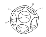
- FIG. 1 is a diagram showing an outline of an example of a metal porous body according to the present disclosure.
- FIG. 2 is a cross-sectional photograph of an example of the metal porous body according to the present disclosure.
- FIG. 3 is a schematic view of a structural unit of a three-dimensional network structure of a metal porous body according to the present disclosure.
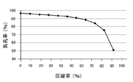
- FIG. 4 is a diagram showing the relationship between the porosity (%) and the compression rate (%) of a metal porous body having a skeleton having a three-dimensional network structure.
- FIG. 5 is a diagram showing an outline of a step of cutting a metal porous body in a direction orthogonal to a thickness direction in an example of the method for producing a metal porous body according to the present disclosure.
- a polyurethane resin is used as the resin porous body
- a block-shaped polyurethane resin is peeled or sliced to form a flat plate.
- the surface of the polyurethane resin skeleton is conductively treated.
- a certain amount of tension is applied to the resin porous body in the plating solution.
- the thickness of the resin porous body is orthogonal to the thickness direction.
- a method for producing a metal porous body having a thickness of 1.0 mm or less for example, a method of producing a metal porous body having a thickness of more than 1.0 mm and then rolling the metal porous body to have a thickness of 1.0 mm or less is also available. Conceivable. However, in the metal porous body having a thickness of 1.0 mm or less by rolling, the cells are crushed in the thickness direction, and as a result, the porosity is reduced. Therefore, when a metal porous body having a thickness of 1.0 mm or less by rolling is used as a filter, for example, there is a problem that the pressure loss becomes large.
- an object of the present disclosure is to provide a flat metal porous body having a thickness of less than twice the cell diameter in the direction orthogonal to the thickness direction.
- the metal porous body according to one aspect of the present disclosure is A flat metal porous body having a three-dimensional network-like skeleton. Contains multiple cells When the ratio of the cell diameter in the thickness direction of the metal porous body to the cell diameter in the direction orthogonal to the thickness direction (cell diameter in the thickness direction / cell diameter in the plane direction) is taken as the cell diameter ratio, the following equation (1) And a metal porous body satisfying the following formula (2).
- the cell diameter in the direction orthogonal to the thickness direction of the metal porous body may be more than 0.4 mm and 1.70 mm or less. According to this aspect, it is possible to provide a metal porous body having a thickness of 0.8 mm or less even if the cell diameter in the direction orthogonal to the thickness direction is larger than 0.4 mm.
- the metal porous body is The thickness may be 0.5 mm or more and 1.2 mm or less. According to this aspect, it is possible to provide a metal porous body having a cell diameter of more than 0.6 mm in a direction orthogonal to the thickness direction even if the thickness is as thin as 1.2 mm or less.
- the metal porous body is The porosity may be 94% or more and 99% or less. According to this aspect, it is possible to provide a metal porous body having a high porosity.
- the metal porous body is The basis weight may be 100 g / m 2 or more and 250 g / m 2 or less. According to this aspect, it is possible to provide a very lightweight metal porous body.
- the basis weight means the weight of the metal porous body with respect to the area calculated from the outer shape when the metal porous body is viewed in a plan view.
- the method for producing a porous metal body according to one aspect of the present disclosure is as follows.
- the method for producing a metal porous body according to the above [1]. A process of conducting a conductive treatment on the surface of the skeleton of a flat resin porous body having a skeleton of a three-dimensional network structure, Next, a step of plating the surface of the skeleton of the resin porous body with a metal, Next, a step of removing the resin porous body to obtain a thick plate-shaped metal porous body, and Next, a step of cutting the thick plate-shaped metal porous body in a direction orthogonal to the thickness direction to obtain a metal porous body, and It is a method for producing a metal porous body having the above. According to this aspect, it is possible to provide a method capable of producing a flat metal porous body having a thickness of less than twice the cell diameter in the direction orthogonal to the thickness direction.
- the method for producing the metal porous body is as follows. A step of further compressing the metal porous body cut in a direction orthogonal to the thickness direction may be performed in the thickness direction. According to this aspect, it is possible to provide a method for producing a metal porous body capable of maintaining a flat plate shape more stably.
- the metal porous body 10 has a skeleton 11 having a three-dimensional network structure.
- the metal porous body 10 has a flat plate-like appearance as a whole.
- the structural unit of the three-dimensional network structure is regarded as a regular dodecahedron.
- the structural unit of the three-dimensional network structure includes one cell 12.
- the cell 12 includes pores 13 which are three-dimensional spaces formed by the skeleton 11 having a three-dimensional network structure.
- the cell diameter is defined by the longest diagonal line of the regular dodecahedron.
- the skeleton 11 is typically composed of a film made of metal or alloy, and the inside of the skeleton 11 is hollow.
- Examples of the metal constituting the skeleton 11 include nickel, aluminum, copper and the like. Further, examples of the alloy constituting the skeleton 11 include alloys formed by unavoidably or intentionally adding another metal to the metal. Examples of the alloy constituting the skeleton 11 include alloys of chromium, cobalt, tin and the like with nickel (NiCr, NiCo, NiSn and the like). Further, the skeleton 11 may have a laminated structure having two or more layers of a film made of the metal or the alloy by plating the surface of the metal or the alloy with another metal. Twice
- the metal porous body 10 includes pores 13 which are three-dimensional spaces and has a three-dimensional network structure. Therefore, it can be clearly distinguished from a two-dimensional network structure having only planar holes (for example, punching metal, mesh, etc.). Further, as shown in FIGS. 1 to 3, since the metal porous body 10 has a skeleton 11 having a three-dimensional network structure, it is clearly distinguished from a structure such as a non-woven fabric formed by entwining fibers with each other. be able to. Since the metal porous body 10 has such a three-dimensional network structure, it has a plurality of pores connecting from the surface to the inside.
- the cell diameter in the thickness direction of the metal porous body 10 is calculated by the following formula (4), or the cell diameter in the cross section of the metal porous body 10 in the thickness direction is actually measured.
- Cell diameter in the thickness direction Cell diameter in the direction orthogonal to the thickness direction ⁇ (1-compression rate / 100) Equation (4)
- the compression rate (%) in the formula (4) can be obtained from the graph showing the relationship between the porosity and the compression rate shown in FIG. In FIG. 5, the vertical axis represents the porosity (%) of the metal porous body, and the horizontal axis represents the compressibility (%) of the metal porous body.
- the cell diameter of the cross section of the metal porous body 10 in the thickness direction is actually measured, the cell diameter measured as follows is referred to as the cell diameter in the thickness direction.
- the metal porous body 10 is embedded in a resin, cut in the thickness direction, and its cross section is observed. Subsequently, 10 circles of the cell 12 are arbitrarily drawn in the cross section, and the average of the cell diameters is calculated.
- the porosity of the metal porous body 10 is defined by the following formula (5).
- Porosity (%) [1- ⁇ Mp / (Vp ⁇ dp) ⁇ ] ⁇ 100 Equation (5)
- Mp Mass of metal porous body [g]
- Vp Volume of appearance shape in metal porous body [cm 3 ]
- dp Density of metals constituting the metal porous body [g / cm 3 ]
- the thickness of the metal porous body 10 can be measured by, for example, a digital thickness gauge.
- the cell diameter ratio means how much the metal porous body 10 is compressed in the thickness direction after being manufactured.
- the cell diameter ratio may be 0.4 or more and 1.0 or less, preferably 0.5 or more and 1.0 or less, and more preferably 0.7 or more and 1.0 or less. Since the shape of the cell 12 can be modeled as a regular dodecahedron, when the metal porous body 10 is not compressed in the thickness direction by rolling or the like, the cell diameter in the thickness direction and the direction orthogonal to the thickness direction There is no difference from the cell diameter. Therefore, when the cell diameter ratio is 1.0, it means that the metal porous body 10 is not compressed in the thickness direction after production.
- the cell diameter ratio is preferably close to 1.0 from the viewpoint of reducing the pressure loss.
- the cell diameter ratio is 0.4, it means that the compressibility of the metal porous body 10 in the thickness direction is 60%.
- thickness of metal porous body / cell diameter ratio means the thickness of the metal porous body 10 before compression in the thickness direction. This is because, as described above, the cell diameter ratio means how much the metal porous body 10 is compressed in the thickness direction, so the thickness of the compressed metal porous body 10 is divided by the cell diameter ratio. As a result, the thickness of the metal porous body 10 before compression is calculated.
- the cell diameter in the direction orthogonal to the thickness direction of the metal porous body 10 may be appropriately selected according to the application of the metal porous body 10.
- the cell diameter in the direction orthogonal to the thickness direction is preferably more than 0.40 mm and preferably 1.70 mm or less, more preferably 0.5 mm or more and 1.1 mm or less, and more preferably 1.0 mm. The following is more preferable. Even if the cell diameter in the direction orthogonal to the thickness direction of the metal porous body 10 exceeds 0.40 mm, the thickness can be, for example, 1.0 mm or less or 0.5 mm or less.
- the mesh when it is used as a filter, the mesh can be made thinner without making the mesh too fine, and the pressure loss can also be reduced. Further, when it is used as an electrode of a battery, the filling property of an active material can be improved, and when it is used as an electrode of a hydrogen generator, the gas escape property generated at the electrode can be improved.
- the thickness of the metal porous body 10 may be appropriately selected according to the use of the metal porous body 10.
- the thickness of the metal porous body 10 is preferably 0.5 mm or more and 1.2 mm or less. Even if the thickness of the metal porous body 10 is 1.2 mm or less, the cell diameter in the direction orthogonal to the thickness direction can be made larger than 0.6 mm.
- the metal porous body 10 has a porosity excluding the volume of the resin porous body used as the base material at the time of production.
- the porosity of the metal porous body 10 changes as shown in the graph shown in FIG. 4 according to the compressibility. For example, even if the metal porous body 10 is rolled so that the compressibility is about 60%, the porosity of the metal porous body 10 remains larger than 90%.
- the porosity of the metal porous body 10 may be appropriately selected according to the use of the metal porous body 10.
- the porosity of the metal porous body 10 is preferably 94% or more and 99% or less, more preferably 96% or more and 99% or less, and 97% or more and 99% or less. Is even more preferable.
- the basis weight of the metal porous body 10 may be appropriately selected according to the use of the metal porous body 10.
- the basis weight of the metal porous body 10 is preferably 100 g / m 2 or more and 250 g / m 2 or less. Since the metal porous body 10 is obtained by cutting the metal porous body produced by the so-called plating method in the direction orthogonal to the thickness direction, the basis weight is 1/2 or less of the basis weight of the metal porous body before cutting. be. Therefore, the metal porous body 10 is easy to provide as a very lightweight one. Of course, depending on the use of the metal porous body, a high basis weight may be used.
- the method for producing a metal porous body according to the embodiment of the present disclosure includes a step of conducting a conductive treatment on the surface of the skeleton of a flat plate-shaped resin porous body having a skeleton having a three-dimensional network structure, and a conductive treatment on the surface of the skeleton.
- a flat plate-shaped resin porous body having a skeleton having a three-dimensional network structure (hereinafter, also simply referred to as “resin porous body”) is prepared.
- resin porous body a polyurethane resin, a melamine resin or the like can be used.
- the resin porous body is used as a base material when producing a metal porous body. Therefore, the cell diameter, porosity, and thickness in the direction orthogonal to the thickness direction of the resin porous body may be the same as those of the metal porous body for manufacturing purposes.
- a coating material containing a conductive powder such as carbon powder is applied to the surface of the resin porous body skeleton to make the surface of the resin porous body skeleton conductive.
- a conductive powder such as carbon powder
- the carbon powder include amorphous carbon powder such as carbon black and carbon powder such as graphite.
- Metal plating process In this step, a metal is plated using a resin porous body in which the surface of the skeleton is conductive-treated as a base material. Since the surface of the skeleton of the resin porous body is subjected to a conductive treatment, it is preferable to perform metal plating by electroplating.
- the type of metal to be plated on the resin porous body is not particularly limited. The type of metal may be appropriately selected according to the use of the porous metal body. For example, in the case of a metal such as nickel, aluminum or copper, electroplating can be performed by a known plating method. Two or more kinds of metals may be plated and alloyed. For example, after plating nickel, chromium, cobalt, tin, etc.
- the plating amount of the metal is not particularly limited, and the plating amount may be adjusted so that the metal porous body 10 to be manufactured has a preferable basis weight.
- the metal porous body 10 is obtained by cutting the metal porous body obtained by removing the resin porous body plated with metal in a direction orthogonal to the thickness direction. Therefore, in the step of plating the metal, the amount of metal plating may be adjusted while keeping in mind that the amount of the metal porous body 10 has a grain size of 1/2 or less of the amount of the metal porous body before cutting.
- Step of removing the resin porous body This step is a step of removing the resin porous body used as the base material from the structure in which the film made of metal or alloy is formed on the surface of the skeleton.
- the resin porous body can be removed by heat treatment in an oxidizing atmosphere such as the atmosphere at a temperature of 600 ° C. or higher and 800 ° C. or lower, preferably 600 ° C. or higher and 700 ° C. or lower.
- the resin porous body used as the base material is burnt off, and a metal porous body in which the skeleton is formed of the film made of the metal or alloy is obtained.
- the oxidized metal or alloy may be reduced by heat treatment in a reducing atmosphere, if necessary.
- Step of cutting metal porous body As shown in FIG. 5, this step is performed by cutting the thick plate-shaped metal porous body 20 obtained by removing the resin porous body in a direction orthogonal to the thickness direction (Z-axis direction in FIG. 1). This is a step of obtaining the metal porous body 10 according to the embodiment. As described above, if the resin porous body used as the base material does not have a thickness of at least twice the cell diameter in the direction orthogonal to the thickness direction, the skeleton of the three-dimensional network structure cannot be maintained and the structure is formed. It will break.
- the thick plate-shaped metal porous body 20 may be cut so that the metal porous body 10 satisfying the formula (2) can be obtained.
- the method for cutting the thick plate-shaped metal porous body 20 is not particularly limited.
- the main surfaces of the thick plate-shaped metal porous body 20 may be fixed to each other with a jig, and the space between them may be cut by a rotary blade or the like. .. Further, in the example shown in FIG.
- the thick plate-shaped metal porous body 20 is divided into two in the direction orthogonal to the thickness direction Z, but it may be divided into three or more.
- this is divided into three to obtain three metal porous bodies 10 having a thickness of about 0.66 mm. It is also possible.
- Step of compressing metal porous body This step is a step of compressing the metal porous body 10 cut in the direction orthogonal to the thickness direction in the thickness direction.
- the metal porous body 10 By compressing the metal porous body 10 in the thickness direction, the metal porous body 10 can be made to have a desired thickness, and the flat plate shape can be maintained more stably, and the handleability is improved.
- the metal porous body 10 When the metal porous body 10 is compressed in the thickness direction, the cell 12 is crushed and the porosity is reduced. Therefore, the metal porous body 10 may be compressed so as to have a preferable thickness and porosity according to the intended use within the range satisfying the formula (1).
- Example 1 A polyurethane sheet having a thickness of 2.0 mm was prepared as a resin porous body having a skeleton having a three-dimensional network structure.
- the porosity of the resin porous body was 96%.
- the cell diameter in the direction orthogonal to the thickness direction was 0.85 mm.
- the conductive treatment of the surface of the skeleton of the polyurethane sheet was performed by immersing the polyurethane sheet in a carbon suspension and drying it.
- the components of the carbon suspension were 25% graphite and carbon black, and contained a resin binder, a penetrant and an antifoaming agent.
- the particle size of carbon black was 0.5 ⁇ m.
- Nickel was plated on the surface of the skeleton of the polyurethane sheet in which the surface of the skeleton was conductive-treated so that the basis weight was 500 g / m 2.
- Nickel plating was performed using a watt bath (nickel sulfate 300 g / L, nickel chloride 50 g / L, boric acid 30 g / L).
- the polyurethane sheet used as a base material was burnt off by heating at 650 ° C. for 10 minutes.
- the metal porous body after the reduction treatment was cut into two pieces in a direction orthogonal to the thickness direction Z. As a result, the two metal porous bodies No. 1 having a thickness of 1.0 mm. 1 was obtained.
- Example 2 The metal porous body No. 1 produced in Example 1. 1 is compressed in the thickness direction so that the thickness becomes 0.5 mm, and the metal porous body No. 1 is obtained. 2 was manufactured.
- Example 3 A polyurethane sheet having a thickness of 3.0 mm, a cell diameter of 0.85 mm in the direction orthogonal to the thickness direction, and a porosity of 96% is used, and the metal porous body after further reduction treatment is orthogonal to the thickness direction Z. It was cut into 3 pieces in the direction of Other conditions are the same as in Example 1, and the three metal porous bodies No. 3 was manufactured.
- Example 4 The metal porous body No. 2 produced in Example 3. 3 is compressed in the thickness direction so that the thickness becomes 0.5 mm, and the metal porous body No. 3 is compressed. 4 was manufactured.
- Example 5 A polyurethane sheet having a thickness of 2.0 mm, a cell diameter of 0.54 mm in the direction orthogonal to the thickness direction, and a porosity of 96% was used. Other conditions are the same as those of the production method described in Example 1, and the metal porous body No. 1 having a thickness of 1.0 mm is used. 5 was manufactured.
- Example 6 The metal porous body No. 2 produced in Example 5. No. 5 is compressed in the thickness direction so that the thickness becomes 0.5 mm, and the metal porous body No. 6 was manufactured.
- Example 7 A polyurethane sheet having a thickness of 2.5 mm, a cell diameter of 1.27 mm in the direction orthogonal to the thickness direction, and a porosity of 96% was used. Other conditions are the same as the production method described in Example 1, a metal porous body having a thickness of about 1.2 mm is produced, and this is rolled to a thickness of 1.0 mm to obtain a metal porous body No. 7 was manufactured.
- Example 8 The metal porous body No. 2 produced in Example 7. 7 is compressed in the thickness direction so that the thickness becomes 0.5 mm, and the metal porous body No. 7 is compressed. 8 was manufactured.
- Example 1 In the production method described in Example 1, the metal porous body after the reduction treatment was not cut and was compressed to a thickness of 0.5 mm. Other conditions are the same as in Example 1, and the metal porous body No. 9 was manufactured.
- Example 7 the metal porous body after the reduction treatment was cut into three pieces in a direction orthogonal to the thickness direction Z. Other conditions are the same as in Example 7, and the three metal porous bodies No. 10 was manufactured.
- Metal porous body No. The thickness of 10 was supposed to be about 0.8 mm.
- Table 1 shows various numerical values of the metal porous body that should have been obtained after the cutting step.
- Metal porous body No. 1 to No. Table 1 shows the measured and calculated values for the 10 structures.
- a metal porous body having a large porosity and a large cell diameter can be preferably used, for example, as a filter having a small pressure loss. According to the metal porous body according to the embodiment of the present disclosure, it is possible to select a more preferable cell diameter, porosity, thickness, and basis weight depending on the use of the metal porous body.
Landscapes
- Chemical & Material Sciences (AREA)
- Engineering & Computer Science (AREA)
- Chemical Kinetics & Catalysis (AREA)
- Electrochemistry (AREA)
- Materials Engineering (AREA)
- Metallurgy (AREA)
- Organic Chemistry (AREA)
- General Chemical & Material Sciences (AREA)
- Mechanical Engineering (AREA)
- Textile Engineering (AREA)
- Powder Metallurgy (AREA)
- Cell Electrode Carriers And Collectors (AREA)
- Electroplating Methods And Accessories (AREA)
Priority Applications (3)
| Application Number | Priority Date | Filing Date | Title |
|---|---|---|---|
| CN202180002986.4A CN113840947A (zh) | 2020-03-27 | 2021-02-10 | 金属多孔体及金属多孔体的制造方法 |
| US17/609,126 US20220228281A1 (en) | 2020-03-27 | 2021-02-10 | Porous metal body and method for producing porous metal body |
| JP2021528962A JP7616536B2 (ja) | 2020-03-27 | 2021-02-10 | 金属多孔体および金属多孔体の製造方法 |
Applications Claiming Priority (2)
| Application Number | Priority Date | Filing Date | Title |
|---|---|---|---|
| JP2020057177 | 2020-03-27 | ||
| JP2020-057177 | 2020-03-27 |
Publications (1)
| Publication Number | Publication Date |
|---|---|
| WO2021192698A1 true WO2021192698A1 (ja) | 2021-09-30 |
Family
ID=77891448
Family Applications (1)
| Application Number | Title | Priority Date | Filing Date |
|---|---|---|---|
| PCT/JP2021/005072 Ceased WO2021192698A1 (ja) | 2020-03-27 | 2021-02-10 | 金属多孔体および金属多孔体の製造方法 |
Country Status (4)
| Country | Link |
|---|---|
| US (1) | US20220228281A1 (https=) |
| JP (1) | JP7616536B2 (https=) |
| CN (1) | CN113840947A (https=) |
| WO (1) | WO2021192698A1 (https=) |
Cited By (1)
| Publication number | Priority date | Publication date | Assignee | Title |
|---|---|---|---|---|
| WO2025047085A1 (ja) * | 2023-08-30 | 2025-03-06 | 富山住友電工株式会社 | メッシュ、水電解装置及び燃料電池 |
Citations (8)
| Publication number | Priority date | Publication date | Assignee | Title |
|---|---|---|---|---|
| JPH0531446A (ja) | 1991-08-01 | 1993-02-09 | Sumitomo Electric Ind Ltd | 三次元網状構造金属多孔体の製造方法 |
| JPH11154517A (ja) * | 1997-11-21 | 1999-06-08 | Inoac Corporation:Kk | 二次電池用金属多孔体及びその製造方法 |
| JP2011225950A (ja) | 2010-04-22 | 2011-11-10 | Sumitomo Electric Ind Ltd | アルミニウム構造体の製造方法およびアルミニウム構造体 |
| JP2016023322A (ja) * | 2014-07-17 | 2016-02-08 | 住友電気工業株式会社 | アルミニウム多孔体の製造方法 |
| WO2019082424A1 (ja) * | 2017-10-25 | 2019-05-02 | 富山住友電工株式会社 | 燃料電池及び金属多孔体の製造方法 |
| CN110434341A (zh) * | 2019-08-30 | 2019-11-12 | 西北有色金属研究院 | 一种全连通高孔隙率镍基合金材料的制备方法 |
| WO2020049815A1 (ja) * | 2018-09-07 | 2020-03-12 | 富山住友電工株式会社 | 金属多孔体、燃料電池および金属多孔体の製造方法 |
| JP2020057177A (ja) | 2018-10-02 | 2020-04-09 | 株式会社デンソーウェーブ | 電子機器 |
-
2021
- 2021-02-10 WO PCT/JP2021/005072 patent/WO2021192698A1/ja not_active Ceased
- 2021-02-10 JP JP2021528962A patent/JP7616536B2/ja active Active
- 2021-02-10 US US17/609,126 patent/US20220228281A1/en not_active Abandoned
- 2021-02-10 CN CN202180002986.4A patent/CN113840947A/zh active Pending
Patent Citations (8)
| Publication number | Priority date | Publication date | Assignee | Title |
|---|---|---|---|---|
| JPH0531446A (ja) | 1991-08-01 | 1993-02-09 | Sumitomo Electric Ind Ltd | 三次元網状構造金属多孔体の製造方法 |
| JPH11154517A (ja) * | 1997-11-21 | 1999-06-08 | Inoac Corporation:Kk | 二次電池用金属多孔体及びその製造方法 |
| JP2011225950A (ja) | 2010-04-22 | 2011-11-10 | Sumitomo Electric Ind Ltd | アルミニウム構造体の製造方法およびアルミニウム構造体 |
| JP2016023322A (ja) * | 2014-07-17 | 2016-02-08 | 住友電気工業株式会社 | アルミニウム多孔体の製造方法 |
| WO2019082424A1 (ja) * | 2017-10-25 | 2019-05-02 | 富山住友電工株式会社 | 燃料電池及び金属多孔体の製造方法 |
| WO2020049815A1 (ja) * | 2018-09-07 | 2020-03-12 | 富山住友電工株式会社 | 金属多孔体、燃料電池および金属多孔体の製造方法 |
| JP2020057177A (ja) | 2018-10-02 | 2020-04-09 | 株式会社デンソーウェーブ | 電子機器 |
| CN110434341A (zh) * | 2019-08-30 | 2019-11-12 | 西北有色金属研究院 | 一种全连通高孔隙率镍基合金材料的制备方法 |
Cited By (1)
| Publication number | Priority date | Publication date | Assignee | Title |
|---|---|---|---|---|
| WO2025047085A1 (ja) * | 2023-08-30 | 2025-03-06 | 富山住友電工株式会社 | メッシュ、水電解装置及び燃料電池 |
Also Published As
| Publication number | Publication date |
|---|---|
| JPWO2021192698A1 (https=) | 2021-09-30 |
| US20220228281A1 (en) | 2022-07-21 |
| CN113840947A (zh) | 2021-12-24 |
| JP7616536B2 (ja) | 2025-01-17 |
Similar Documents
| Publication | Publication Date | Title |
|---|---|---|
| EP2666890B1 (en) | Porous metal having high corrosion resistance and process for producing same | |
| CN110856447B (zh) | 多孔体、包括该多孔体的集电体以及燃料电池 | |
| JP7079842B2 (ja) | 金属多孔体 | |
| WO2013099532A1 (ja) | 金属多孔体の製造方法及び金属多孔体 | |
| CN104205427B (zh) | 非水电解质二次电池用电极和使用该电极的非水电解质二次电池 | |
| WO2020049815A1 (ja) | 金属多孔体、燃料電池および金属多孔体の製造方法 | |
| KR20190047660A (ko) | 연료 전지 및 금속 다공체의 제조 방법 | |
| JP7355034B2 (ja) | 多孔体、それを含む燃料電池、およびそれを含む水蒸気電解装置 | |
| CN111183237B (zh) | 金属多孔体、燃料电池和金属多孔体的制造方法 | |
| JP7616536B2 (ja) | 金属多孔体および金属多孔体の製造方法 | |
| WO2022059494A1 (ja) | ニッケルクロム多孔体およびニッケルクロム多孔体の製造方法 | |
| CN114556638A (zh) | 表面被覆金属多孔体 | |
| KR102925161B1 (ko) | 다공체 및, 그것을 포함하는 연료 전지 | |
| EP4641710A1 (en) | Metal sheet, battery, nickel-zinc battery, and metal sheet manufacturing method | |
| CN113383100A (zh) | 多孔体以及包括该多孔体的燃料电池 | |
| EP4641711A1 (en) | Metal sheet, battery, nickel-zinc battery, and method for producing metal sheet | |
| JP2024035329A (ja) | 3次元規則骨格構造を有する金属部材、水電解装置、燃料電池 | |
| JP2019151900A (ja) | 多孔質金属体、集電体、電池および、多孔質金属体の製造方法 |
Legal Events
| Date | Code | Title | Description |
|---|---|---|---|
| ENP | Entry into the national phase |
Ref document number: 2021528962 Country of ref document: JP Kind code of ref document: A |
|
| 121 | Ep: the epo has been informed by wipo that ep was designated in this application |
Ref document number: 21775564 Country of ref document: EP Kind code of ref document: A1 |
|
| NENP | Non-entry into the national phase |
Ref country code: DE |
|
| 122 | Ep: pct application non-entry in european phase |
Ref document number: 21775564 Country of ref document: EP Kind code of ref document: A1 |