WO2021192698A1 - Porous metal body and method for manufacturing porous metal body - Google Patents
Porous metal body and method for manufacturing porous metal body Download PDFInfo
- Publication number
- WO2021192698A1 WO2021192698A1 PCT/JP2021/005072 JP2021005072W WO2021192698A1 WO 2021192698 A1 WO2021192698 A1 WO 2021192698A1 JP 2021005072 W JP2021005072 W JP 2021005072W WO 2021192698 A1 WO2021192698 A1 WO 2021192698A1
- Authority
- WO
- WIPO (PCT)
- Prior art keywords
- porous body
- metal porous
- metal
- cell diameter
- thickness
- Prior art date
Links
Images


Classifications
-
- C—CHEMISTRY; METALLURGY
- C25—ELECTROLYTIC OR ELECTROPHORETIC PROCESSES; APPARATUS THEREFOR
- C25D—PROCESSES FOR THE ELECTROLYTIC OR ELECTROPHORETIC PRODUCTION OF COATINGS; ELECTROFORMING; APPARATUS THEREFOR
- C25D5/00—Electroplating characterised by the process; Pretreatment or after-treatment of workpieces
- C25D5/54—Electroplating of non-metallic surfaces
- C25D5/56—Electroplating of non-metallic surfaces of plastics
-
- B—PERFORMING OPERATIONS; TRANSPORTING
- B01—PHYSICAL OR CHEMICAL PROCESSES OR APPARATUS IN GENERAL
- B01D—SEPARATION
- B01D39/00—Filtering material for liquid or gaseous fluids
- B01D39/10—Filter screens essentially made of metal
- B01D39/12—Filter screens essentially made of metal of wire gauze; of knitted wire; of expanded metal
-
- B—PERFORMING OPERATIONS; TRANSPORTING
- B23—MACHINE TOOLS; METAL-WORKING NOT OTHERWISE PROVIDED FOR
- B23P—METAL-WORKING NOT OTHERWISE PROVIDED FOR; COMBINED OPERATIONS; UNIVERSAL MACHINE TOOLS
- B23P15/00—Making specific metal objects by operations not covered by a single other subclass or a group in this subclass
-
- C—CHEMISTRY; METALLURGY
- C22—METALLURGY; FERROUS OR NON-FERROUS ALLOYS; TREATMENT OF ALLOYS OR NON-FERROUS METALS
- C22C—ALLOYS
- C22C1/00—Making non-ferrous alloys
- C22C1/08—Alloys with open or closed pores
-
- C—CHEMISTRY; METALLURGY
- C25—ELECTROLYTIC OR ELECTROPHORETIC PROCESSES; APPARATUS THEREFOR
- C25B—ELECTROLYTIC OR ELECTROPHORETIC PROCESSES FOR THE PRODUCTION OF COMPOUNDS OR NON-METALS; APPARATUS THEREFOR
- C25B11/00—Electrodes; Manufacture thereof not otherwise provided for
- C25B11/02—Electrodes; Manufacture thereof not otherwise provided for characterised by shape or form
- C25B11/03—Electrodes; Manufacture thereof not otherwise provided for characterised by shape or form perforated or foraminous
- C25B11/031—Porous electrodes
-
- C—CHEMISTRY; METALLURGY
- C25—ELECTROLYTIC OR ELECTROPHORETIC PROCESSES; APPARATUS THEREFOR
- C25D—PROCESSES FOR THE ELECTROLYTIC OR ELECTROPHORETIC PRODUCTION OF COATINGS; ELECTROFORMING; APPARATUS THEREFOR
- C25D1/00—Electroforming
- C25D1/08—Perforated or foraminous objects, e.g. sieves
-
- C—CHEMISTRY; METALLURGY
- C25—ELECTROLYTIC OR ELECTROPHORETIC PROCESSES; APPARATUS THEREFOR
- C25D—PROCESSES FOR THE ELECTROLYTIC OR ELECTROPHORETIC PRODUCTION OF COATINGS; ELECTROFORMING; APPARATUS THEREFOR
- C25D3/00—Electroplating: Baths therefor
- C25D3/02—Electroplating: Baths therefor from solutions
- C25D3/12—Electroplating: Baths therefor from solutions of nickel or cobalt
-
- H—ELECTRICITY
- H01—ELECTRIC ELEMENTS
- H01M—PROCESSES OR MEANS, e.g. BATTERIES, FOR THE DIRECT CONVERSION OF CHEMICAL ENERGY INTO ELECTRICAL ENERGY
- H01M4/00—Electrodes
- H01M4/02—Electrodes composed of, or comprising, active material
- H01M4/64—Carriers or collectors
- H01M4/66—Selection of materials
- H01M4/661—Metal or alloys, e.g. alloy coatings
-
- H—ELECTRICITY
- H01—ELECTRIC ELEMENTS
- H01M—PROCESSES OR MEANS, e.g. BATTERIES, FOR THE DIRECT CONVERSION OF CHEMICAL ENERGY INTO ELECTRICAL ENERGY
- H01M4/00—Electrodes
- H01M4/02—Electrodes composed of, or comprising, active material
- H01M4/64—Carriers or collectors
- H01M4/70—Carriers or collectors characterised by shape or form
- H01M4/80—Porous plates, e.g. sintered carriers
Definitions
- the present invention relates to a metal porous body and a method for producing the metal porous body.
- This application claims priority based on Japanese Application No. 2020-057177 filed on March 27, 2020, and incorporates all the contents described in the Japanese application.
- Sheet-shaped metal porous bodies having a skeleton with a three-dimensional network structure are used in various applications such as filters that require heat resistance, electrode plates for batteries, catalyst carriers, and metal composite materials.
- Celmet manufactured by Sumitomo Electric Industries, Ltd .: registered trademark
- aluminum celmet manufactured by Sumitomo Electric Industries, Ltd .: registered trademark
- aluminum celmet which is a metal porous body made of aluminum, is stable even in an organic electrolyte, and can be used as a positive electrode of a lithium ion battery.
- the surface of the skeleton of the resin porous body having a skeleton having a three-dimensional network structure is conductively treated, and then the surface of the skeleton of the resin porous body is metal-plated by electroplating treatment, followed by resin. It can be produced by removing the porous body (see, for example, Patent Document 1 and Patent Document 2).
- a polyurethane resin can be preferably used as the resin porous body.
- the metal porous body according to one aspect of the present disclosure is A flat metal porous body having a three-dimensional network-like skeleton. Contains multiple cells
- the ratio of the cell diameter in the thickness direction of the metal porous body to the cell diameter in the direction orthogonal to the thickness direction is defined as the cell diameter ratio
- the following A metal porous body satisfying the formula (1) and the following formula (2).
- 0.4 ⁇ cell diameter ratio ⁇ 1.0 Equation (1) 0.50 ⁇ cell diameter in the direction orthogonal to the thickness direction / (thickness of porous metal / cell diameter ratio) ⁇ 1.50 formula (2)
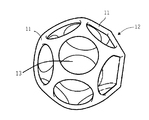
- FIG. 1 is a diagram showing an outline of an example of a metal porous body according to the present disclosure.
- FIG. 2 is a cross-sectional photograph of an example of the metal porous body according to the present disclosure.
- FIG. 3 is a schematic view of a structural unit of a three-dimensional network structure of a metal porous body according to the present disclosure.
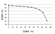
- FIG. 4 is a diagram showing the relationship between the porosity (%) and the compression rate (%) of a metal porous body having a skeleton having a three-dimensional network structure.
- FIG. 5 is a diagram showing an outline of a step of cutting a metal porous body in a direction orthogonal to a thickness direction in an example of the method for producing a metal porous body according to the present disclosure.
- a polyurethane resin is used as the resin porous body
- a block-shaped polyurethane resin is peeled or sliced to form a flat plate.
- the surface of the polyurethane resin skeleton is conductively treated.
- a certain amount of tension is applied to the resin porous body in the plating solution.
- the thickness of the resin porous body is orthogonal to the thickness direction.
- a method for producing a metal porous body having a thickness of 1.0 mm or less for example, a method of producing a metal porous body having a thickness of more than 1.0 mm and then rolling the metal porous body to have a thickness of 1.0 mm or less is also available. Conceivable. However, in the metal porous body having a thickness of 1.0 mm or less by rolling, the cells are crushed in the thickness direction, and as a result, the porosity is reduced. Therefore, when a metal porous body having a thickness of 1.0 mm or less by rolling is used as a filter, for example, there is a problem that the pressure loss becomes large.
- an object of the present disclosure is to provide a flat metal porous body having a thickness of less than twice the cell diameter in the direction orthogonal to the thickness direction.
- the metal porous body according to one aspect of the present disclosure is A flat metal porous body having a three-dimensional network-like skeleton. Contains multiple cells When the ratio of the cell diameter in the thickness direction of the metal porous body to the cell diameter in the direction orthogonal to the thickness direction (cell diameter in the thickness direction / cell diameter in the plane direction) is taken as the cell diameter ratio, the following equation (1) And a metal porous body satisfying the following formula (2).
- the cell diameter in the direction orthogonal to the thickness direction of the metal porous body may be more than 0.4 mm and 1.70 mm or less. According to this aspect, it is possible to provide a metal porous body having a thickness of 0.8 mm or less even if the cell diameter in the direction orthogonal to the thickness direction is larger than 0.4 mm.
- the metal porous body is The thickness may be 0.5 mm or more and 1.2 mm or less. According to this aspect, it is possible to provide a metal porous body having a cell diameter of more than 0.6 mm in a direction orthogonal to the thickness direction even if the thickness is as thin as 1.2 mm or less.
- the metal porous body is The porosity may be 94% or more and 99% or less. According to this aspect, it is possible to provide a metal porous body having a high porosity.
- the metal porous body is The basis weight may be 100 g / m 2 or more and 250 g / m 2 or less. According to this aspect, it is possible to provide a very lightweight metal porous body.
- the basis weight means the weight of the metal porous body with respect to the area calculated from the outer shape when the metal porous body is viewed in a plan view.
- the method for producing a porous metal body according to one aspect of the present disclosure is as follows.
- the method for producing a metal porous body according to the above [1]. A process of conducting a conductive treatment on the surface of the skeleton of a flat resin porous body having a skeleton of a three-dimensional network structure, Next, a step of plating the surface of the skeleton of the resin porous body with a metal, Next, a step of removing the resin porous body to obtain a thick plate-shaped metal porous body, and Next, a step of cutting the thick plate-shaped metal porous body in a direction orthogonal to the thickness direction to obtain a metal porous body, and It is a method for producing a metal porous body having the above. According to this aspect, it is possible to provide a method capable of producing a flat metal porous body having a thickness of less than twice the cell diameter in the direction orthogonal to the thickness direction.
- the method for producing the metal porous body is as follows. A step of further compressing the metal porous body cut in a direction orthogonal to the thickness direction may be performed in the thickness direction. According to this aspect, it is possible to provide a method for producing a metal porous body capable of maintaining a flat plate shape more stably.
- the metal porous body 10 has a skeleton 11 having a three-dimensional network structure.
- the metal porous body 10 has a flat plate-like appearance as a whole.
- the structural unit of the three-dimensional network structure is regarded as a regular dodecahedron.
- the structural unit of the three-dimensional network structure includes one cell 12.
- the cell 12 includes pores 13 which are three-dimensional spaces formed by the skeleton 11 having a three-dimensional network structure.
- the cell diameter is defined by the longest diagonal line of the regular dodecahedron.
- the skeleton 11 is typically composed of a film made of metal or alloy, and the inside of the skeleton 11 is hollow.
- Examples of the metal constituting the skeleton 11 include nickel, aluminum, copper and the like. Further, examples of the alloy constituting the skeleton 11 include alloys formed by unavoidably or intentionally adding another metal to the metal. Examples of the alloy constituting the skeleton 11 include alloys of chromium, cobalt, tin and the like with nickel (NiCr, NiCo, NiSn and the like). Further, the skeleton 11 may have a laminated structure having two or more layers of a film made of the metal or the alloy by plating the surface of the metal or the alloy with another metal. Twice
- the metal porous body 10 includes pores 13 which are three-dimensional spaces and has a three-dimensional network structure. Therefore, it can be clearly distinguished from a two-dimensional network structure having only planar holes (for example, punching metal, mesh, etc.). Further, as shown in FIGS. 1 to 3, since the metal porous body 10 has a skeleton 11 having a three-dimensional network structure, it is clearly distinguished from a structure such as a non-woven fabric formed by entwining fibers with each other. be able to. Since the metal porous body 10 has such a three-dimensional network structure, it has a plurality of pores connecting from the surface to the inside.
- the cell diameter in the thickness direction of the metal porous body 10 is calculated by the following formula (4), or the cell diameter in the cross section of the metal porous body 10 in the thickness direction is actually measured.
- Cell diameter in the thickness direction Cell diameter in the direction orthogonal to the thickness direction ⁇ (1-compression rate / 100) Equation (4)
- the compression rate (%) in the formula (4) can be obtained from the graph showing the relationship between the porosity and the compression rate shown in FIG. In FIG. 5, the vertical axis represents the porosity (%) of the metal porous body, and the horizontal axis represents the compressibility (%) of the metal porous body.
- the cell diameter of the cross section of the metal porous body 10 in the thickness direction is actually measured, the cell diameter measured as follows is referred to as the cell diameter in the thickness direction.
- the metal porous body 10 is embedded in a resin, cut in the thickness direction, and its cross section is observed. Subsequently, 10 circles of the cell 12 are arbitrarily drawn in the cross section, and the average of the cell diameters is calculated.
- the porosity of the metal porous body 10 is defined by the following formula (5).
- Porosity (%) [1- ⁇ Mp / (Vp ⁇ dp) ⁇ ] ⁇ 100 Equation (5)
- Mp Mass of metal porous body [g]
- Vp Volume of appearance shape in metal porous body [cm 3 ]
- dp Density of metals constituting the metal porous body [g / cm 3 ]
- the thickness of the metal porous body 10 can be measured by, for example, a digital thickness gauge.
- the cell diameter ratio means how much the metal porous body 10 is compressed in the thickness direction after being manufactured.
- the cell diameter ratio may be 0.4 or more and 1.0 or less, preferably 0.5 or more and 1.0 or less, and more preferably 0.7 or more and 1.0 or less. Since the shape of the cell 12 can be modeled as a regular dodecahedron, when the metal porous body 10 is not compressed in the thickness direction by rolling or the like, the cell diameter in the thickness direction and the direction orthogonal to the thickness direction There is no difference from the cell diameter. Therefore, when the cell diameter ratio is 1.0, it means that the metal porous body 10 is not compressed in the thickness direction after production.
- the cell diameter ratio is preferably close to 1.0 from the viewpoint of reducing the pressure loss.
- the cell diameter ratio is 0.4, it means that the compressibility of the metal porous body 10 in the thickness direction is 60%.
- thickness of metal porous body / cell diameter ratio means the thickness of the metal porous body 10 before compression in the thickness direction. This is because, as described above, the cell diameter ratio means how much the metal porous body 10 is compressed in the thickness direction, so the thickness of the compressed metal porous body 10 is divided by the cell diameter ratio. As a result, the thickness of the metal porous body 10 before compression is calculated.
- the cell diameter in the direction orthogonal to the thickness direction of the metal porous body 10 may be appropriately selected according to the application of the metal porous body 10.
- the cell diameter in the direction orthogonal to the thickness direction is preferably more than 0.40 mm and preferably 1.70 mm or less, more preferably 0.5 mm or more and 1.1 mm or less, and more preferably 1.0 mm. The following is more preferable. Even if the cell diameter in the direction orthogonal to the thickness direction of the metal porous body 10 exceeds 0.40 mm, the thickness can be, for example, 1.0 mm or less or 0.5 mm or less.
- the mesh when it is used as a filter, the mesh can be made thinner without making the mesh too fine, and the pressure loss can also be reduced. Further, when it is used as an electrode of a battery, the filling property of an active material can be improved, and when it is used as an electrode of a hydrogen generator, the gas escape property generated at the electrode can be improved.
- the thickness of the metal porous body 10 may be appropriately selected according to the use of the metal porous body 10.
- the thickness of the metal porous body 10 is preferably 0.5 mm or more and 1.2 mm or less. Even if the thickness of the metal porous body 10 is 1.2 mm or less, the cell diameter in the direction orthogonal to the thickness direction can be made larger than 0.6 mm.
- the metal porous body 10 has a porosity excluding the volume of the resin porous body used as the base material at the time of production.
- the porosity of the metal porous body 10 changes as shown in the graph shown in FIG. 4 according to the compressibility. For example, even if the metal porous body 10 is rolled so that the compressibility is about 60%, the porosity of the metal porous body 10 remains larger than 90%.
- the porosity of the metal porous body 10 may be appropriately selected according to the use of the metal porous body 10.
- the porosity of the metal porous body 10 is preferably 94% or more and 99% or less, more preferably 96% or more and 99% or less, and 97% or more and 99% or less. Is even more preferable.
- the basis weight of the metal porous body 10 may be appropriately selected according to the use of the metal porous body 10.
- the basis weight of the metal porous body 10 is preferably 100 g / m 2 or more and 250 g / m 2 or less. Since the metal porous body 10 is obtained by cutting the metal porous body produced by the so-called plating method in the direction orthogonal to the thickness direction, the basis weight is 1/2 or less of the basis weight of the metal porous body before cutting. be. Therefore, the metal porous body 10 is easy to provide as a very lightweight one. Of course, depending on the use of the metal porous body, a high basis weight may be used.
- the method for producing a metal porous body according to the embodiment of the present disclosure includes a step of conducting a conductive treatment on the surface of the skeleton of a flat plate-shaped resin porous body having a skeleton having a three-dimensional network structure, and a conductive treatment on the surface of the skeleton.
- a flat plate-shaped resin porous body having a skeleton having a three-dimensional network structure (hereinafter, also simply referred to as “resin porous body”) is prepared.
- resin porous body a polyurethane resin, a melamine resin or the like can be used.
- the resin porous body is used as a base material when producing a metal porous body. Therefore, the cell diameter, porosity, and thickness in the direction orthogonal to the thickness direction of the resin porous body may be the same as those of the metal porous body for manufacturing purposes.
- a coating material containing a conductive powder such as carbon powder is applied to the surface of the resin porous body skeleton to make the surface of the resin porous body skeleton conductive.
- a conductive powder such as carbon powder
- the carbon powder include amorphous carbon powder such as carbon black and carbon powder such as graphite.
- Metal plating process In this step, a metal is plated using a resin porous body in which the surface of the skeleton is conductive-treated as a base material. Since the surface of the skeleton of the resin porous body is subjected to a conductive treatment, it is preferable to perform metal plating by electroplating.
- the type of metal to be plated on the resin porous body is not particularly limited. The type of metal may be appropriately selected according to the use of the porous metal body. For example, in the case of a metal such as nickel, aluminum or copper, electroplating can be performed by a known plating method. Two or more kinds of metals may be plated and alloyed. For example, after plating nickel, chromium, cobalt, tin, etc.
- the plating amount of the metal is not particularly limited, and the plating amount may be adjusted so that the metal porous body 10 to be manufactured has a preferable basis weight.
- the metal porous body 10 is obtained by cutting the metal porous body obtained by removing the resin porous body plated with metal in a direction orthogonal to the thickness direction. Therefore, in the step of plating the metal, the amount of metal plating may be adjusted while keeping in mind that the amount of the metal porous body 10 has a grain size of 1/2 or less of the amount of the metal porous body before cutting.
- Step of removing the resin porous body This step is a step of removing the resin porous body used as the base material from the structure in which the film made of metal or alloy is formed on the surface of the skeleton.
- the resin porous body can be removed by heat treatment in an oxidizing atmosphere such as the atmosphere at a temperature of 600 ° C. or higher and 800 ° C. or lower, preferably 600 ° C. or higher and 700 ° C. or lower.
- the resin porous body used as the base material is burnt off, and a metal porous body in which the skeleton is formed of the film made of the metal or alloy is obtained.
- the oxidized metal or alloy may be reduced by heat treatment in a reducing atmosphere, if necessary.
- Step of cutting metal porous body As shown in FIG. 5, this step is performed by cutting the thick plate-shaped metal porous body 20 obtained by removing the resin porous body in a direction orthogonal to the thickness direction (Z-axis direction in FIG. 1). This is a step of obtaining the metal porous body 10 according to the embodiment. As described above, if the resin porous body used as the base material does not have a thickness of at least twice the cell diameter in the direction orthogonal to the thickness direction, the skeleton of the three-dimensional network structure cannot be maintained and the structure is formed. It will break.
- the thick plate-shaped metal porous body 20 may be cut so that the metal porous body 10 satisfying the formula (2) can be obtained.
- the method for cutting the thick plate-shaped metal porous body 20 is not particularly limited.
- the main surfaces of the thick plate-shaped metal porous body 20 may be fixed to each other with a jig, and the space between them may be cut by a rotary blade or the like. .. Further, in the example shown in FIG.
- the thick plate-shaped metal porous body 20 is divided into two in the direction orthogonal to the thickness direction Z, but it may be divided into three or more.
- this is divided into three to obtain three metal porous bodies 10 having a thickness of about 0.66 mm. It is also possible.
- Step of compressing metal porous body This step is a step of compressing the metal porous body 10 cut in the direction orthogonal to the thickness direction in the thickness direction.
- the metal porous body 10 By compressing the metal porous body 10 in the thickness direction, the metal porous body 10 can be made to have a desired thickness, and the flat plate shape can be maintained more stably, and the handleability is improved.
- the metal porous body 10 When the metal porous body 10 is compressed in the thickness direction, the cell 12 is crushed and the porosity is reduced. Therefore, the metal porous body 10 may be compressed so as to have a preferable thickness and porosity according to the intended use within the range satisfying the formula (1).
- Example 1 A polyurethane sheet having a thickness of 2.0 mm was prepared as a resin porous body having a skeleton having a three-dimensional network structure.
- the porosity of the resin porous body was 96%.
- the cell diameter in the direction orthogonal to the thickness direction was 0.85 mm.
- the conductive treatment of the surface of the skeleton of the polyurethane sheet was performed by immersing the polyurethane sheet in a carbon suspension and drying it.
- the components of the carbon suspension were 25% graphite and carbon black, and contained a resin binder, a penetrant and an antifoaming agent.
- the particle size of carbon black was 0.5 ⁇ m.
- Nickel was plated on the surface of the skeleton of the polyurethane sheet in which the surface of the skeleton was conductive-treated so that the basis weight was 500 g / m 2.
- Nickel plating was performed using a watt bath (nickel sulfate 300 g / L, nickel chloride 50 g / L, boric acid 30 g / L).
- the polyurethane sheet used as a base material was burnt off by heating at 650 ° C. for 10 minutes.
- the metal porous body after the reduction treatment was cut into two pieces in a direction orthogonal to the thickness direction Z. As a result, the two metal porous bodies No. 1 having a thickness of 1.0 mm. 1 was obtained.
- Example 2 The metal porous body No. 1 produced in Example 1. 1 is compressed in the thickness direction so that the thickness becomes 0.5 mm, and the metal porous body No. 1 is obtained. 2 was manufactured.
- Example 3 A polyurethane sheet having a thickness of 3.0 mm, a cell diameter of 0.85 mm in the direction orthogonal to the thickness direction, and a porosity of 96% is used, and the metal porous body after further reduction treatment is orthogonal to the thickness direction Z. It was cut into 3 pieces in the direction of Other conditions are the same as in Example 1, and the three metal porous bodies No. 3 was manufactured.
- Example 4 The metal porous body No. 2 produced in Example 3. 3 is compressed in the thickness direction so that the thickness becomes 0.5 mm, and the metal porous body No. 3 is compressed. 4 was manufactured.
- Example 5 A polyurethane sheet having a thickness of 2.0 mm, a cell diameter of 0.54 mm in the direction orthogonal to the thickness direction, and a porosity of 96% was used. Other conditions are the same as those of the production method described in Example 1, and the metal porous body No. 1 having a thickness of 1.0 mm is used. 5 was manufactured.
- Example 6 The metal porous body No. 2 produced in Example 5. No. 5 is compressed in the thickness direction so that the thickness becomes 0.5 mm, and the metal porous body No. 6 was manufactured.
- Example 7 A polyurethane sheet having a thickness of 2.5 mm, a cell diameter of 1.27 mm in the direction orthogonal to the thickness direction, and a porosity of 96% was used. Other conditions are the same as the production method described in Example 1, a metal porous body having a thickness of about 1.2 mm is produced, and this is rolled to a thickness of 1.0 mm to obtain a metal porous body No. 7 was manufactured.
- Example 8 The metal porous body No. 2 produced in Example 7. 7 is compressed in the thickness direction so that the thickness becomes 0.5 mm, and the metal porous body No. 7 is compressed. 8 was manufactured.
- Example 1 In the production method described in Example 1, the metal porous body after the reduction treatment was not cut and was compressed to a thickness of 0.5 mm. Other conditions are the same as in Example 1, and the metal porous body No. 9 was manufactured.
- Example 7 the metal porous body after the reduction treatment was cut into three pieces in a direction orthogonal to the thickness direction Z. Other conditions are the same as in Example 7, and the three metal porous bodies No. 10 was manufactured.
- Metal porous body No. The thickness of 10 was supposed to be about 0.8 mm.
- Table 1 shows various numerical values of the metal porous body that should have been obtained after the cutting step.
- Metal porous body No. 1 to No. Table 1 shows the measured and calculated values for the 10 structures.
- a metal porous body having a large porosity and a large cell diameter can be preferably used, for example, as a filter having a small pressure loss. According to the metal porous body according to the embodiment of the present disclosure, it is possible to select a more preferable cell diameter, porosity, thickness, and basis weight depending on the use of the metal porous body.
Landscapes
- Chemical & Material Sciences (AREA)
- Engineering & Computer Science (AREA)
- Chemical Kinetics & Catalysis (AREA)
- Electrochemistry (AREA)
- Materials Engineering (AREA)
- Organic Chemistry (AREA)
- Metallurgy (AREA)
- General Chemical & Material Sciences (AREA)
- Mechanical Engineering (AREA)
- Textile Engineering (AREA)
- Powder Metallurgy (AREA)
- Cell Electrode Carriers And Collectors (AREA)
- Electroplating Methods And Accessories (AREA)
Abstract
Provided is a porous metal body in the shape of a flat plate having a three-dimensional net-like skeleton, the porous metal body comprising a plurality of cells, wherein expressions (1) and (2) below are satisfied. (1): 0.4≤cell diameter ratio≤1.0, (2): 0.50<cell diameter in the direction perpendicular to the thickness direction/(thickness of porous metal body/cell diameter ratio)≤1.50. The cell diameter ratio is the ratio of the cell diameter in the thickness direction to the cell diameter in the direction perpendicular to the thickness direction in the porous metal body (cell diameter in the thickness direction/cell diameter in the direction perpendicular to the thickness direction).
Description
本発明は、金属多孔体および金属多孔体の製造方法に関する。本出願は、2020年3月27日出願の日本出願第2020-057177号に基づく優先権を主張し、前記日本出願に記載された全ての記載内容を援用するものである。
The present invention relates to a metal porous body and a method for producing the metal porous body. This application claims priority based on Japanese Application No. 2020-057177 filed on March 27, 2020, and incorporates all the contents described in the Japanese application.
三次元網目状構造の骨格を有するシート状の金属多孔体は、耐熱性を必要とするフィルターや、電池用電極板、触媒担持体、及び金属複合材など様々な用途に利用されている。例えば、ニッケル製の金属多孔体であるセルメット(住友電気工業株式会社製:登録商標)は、ニッケル水素電池等のアルカリ蓄電池の電極や、工業用脱臭触媒の担体等、様々な産業分野で広く採用されている。また、アルミニウム製の金属多孔体であるアルミセルメット(住友電気工業株式会社製:登録商標)は、有機電解液中でも安定であるため、リチウムイオン電池の正極として用いることが可能である。
Sheet-shaped metal porous bodies having a skeleton with a three-dimensional network structure are used in various applications such as filters that require heat resistance, electrode plates for batteries, catalyst carriers, and metal composite materials. For example, Celmet (manufactured by Sumitomo Electric Industries, Ltd .: registered trademark), which is a metal porous body made of nickel, is widely used in various industrial fields such as electrodes for alkaline storage batteries such as nickel hydrogen batteries and carriers for industrial deodorizing catalysts. Has been done. Further, aluminum celmet (manufactured by Sumitomo Electric Industries, Ltd .: registered trademark), which is a metal porous body made of aluminum, is stable even in an organic electrolyte, and can be used as a positive electrode of a lithium ion battery.
前記金属多孔体は、三次元網目状構造の骨格を有する樹脂多孔体の骨格の表面を導電化処理した後、電気めっき処理によって前記樹脂多孔体の骨格の表面に金属めっきを施し、続いて樹脂多孔体を除去することによって製造することができる(例えば特許文献1、特許文献2参照)。前記樹脂多孔体としては、例えば、ポリウレタン樹脂を好ましく用いることができる。
In the metal porous body, the surface of the skeleton of the resin porous body having a skeleton having a three-dimensional network structure is conductively treated, and then the surface of the skeleton of the resin porous body is metal-plated by electroplating treatment, followed by resin. It can be produced by removing the porous body (see, for example, Patent Document 1 and Patent Document 2). As the resin porous body, for example, a polyurethane resin can be preferably used.
本開示の一態様に係る金属多孔体は、
三次元網目状構造の骨格を有する平板状の金属多孔体であって、
複数のセルを含み、
前記金属多孔体の厚み方向のセル径と厚み方向と直交する方向のセル径との比(厚み方向のセル径/厚み方向と直交する方向のセル径)をセル径比とした場合に、下記式(1)および下記式(2)を満たす、金属多孔体。
0.4≦セル径比≦1.0 式(1)
0.50<厚み方向と直交する方向のセル径/(金属多孔体の厚み/セル径比)≦1.50 式(2) The metal porous body according to one aspect of the present disclosure is
A flat metal porous body having a three-dimensional network-like skeleton.
Contains multiple cells
When the ratio of the cell diameter in the thickness direction of the metal porous body to the cell diameter in the direction orthogonal to the thickness direction (cell diameter in the thickness direction / cell diameter in the direction orthogonal to the thickness direction) is defined as the cell diameter ratio, the following A metal porous body satisfying the formula (1) and the following formula (2).
0.4 ≤ cell diameter ratio ≤ 1.0 Equation (1)
0.50 <cell diameter in the direction orthogonal to the thickness direction / (thickness of porous metal / cell diameter ratio) ≤ 1.50 formula (2)
[本開示が解決しようとする課題]
樹脂多孔体としてポリウレタン樹脂を用いる場合には、まず、ブロック状のポリウレタン樹脂をピーリングまたはスライスすることにより平板状に加工する。続いてポリウレタン樹脂の骨格の表面を導電化処理する。骨格の表面を導電化処理した前記樹脂多孔体に金属めっきをする際には、めっき液中で前記樹脂多孔体にある程度のテンションが加えられる。ポリウレタン樹脂をピーリングまたはスライスしたり、導電処理やめっき処理したりする際に、樹脂多孔体が三次元網目状構造の骨格を維持するためには、樹脂多孔体の厚みは、厚み方向と直交する方向のセル径の2倍以上である必要がある。このため、例えば、厚みが1.0mmの金属多孔体を製造するためには、厚み方向と直交する方向のセル径が0.50mm以下の樹脂多孔体を用いる必要があった。換言すれば、厚みが1.0mm以下の樹脂多孔体を用いる場合には、厚み方向と直交する方向のセル径が0.50mmよりも大きい金属多孔体を製造することはできなかった。 [Issues to be solved by this disclosure]
When a polyurethane resin is used as the resin porous body, first, a block-shaped polyurethane resin is peeled or sliced to form a flat plate. Subsequently, the surface of the polyurethane resin skeleton is conductively treated. When metal-plating the resin porous body whose surface of the skeleton is conductive-treated, a certain amount of tension is applied to the resin porous body in the plating solution. In order for the resin porous body to maintain the skeleton of the three-dimensional network structure when the polyurethane resin is peeled or sliced, or subjected to conductive treatment or plating treatment, the thickness of the resin porous body is orthogonal to the thickness direction. It must be at least twice the cell diameter in the direction. Therefore, for example, in order to produce a metal porous body having a thickness of 1.0 mm, it is necessary to use a resin porous body having a cell diameter of 0.50 mm or less in a direction orthogonal to the thickness direction. In other words, when a resin porous body having a thickness of 1.0 mm or less is used, it is not possible to produce a metal porous body having a cell diameter larger than 0.50 mm in the direction orthogonal to the thickness direction.
厚みが1.0mm以下の金属多孔体を製造する方法としては、例えば、厚みが1.0mmよりも厚い金属多孔体を作製してからこれを圧延して厚みを1.0mm以下とする方法も考えられる。しかしながら、圧延することによって厚みを1.0mm以下とした金属多孔体は、セルが厚み方向に潰れてしまい、その結果、気孔率が小さくなってしまう。このため、圧延することによって厚みを1.0mm以下とした金属多孔体を、例えばフィルターとして用いる場合には、圧力損失が大きくなってしまうという問題があった。
As a method for producing a metal porous body having a thickness of 1.0 mm or less, for example, a method of producing a metal porous body having a thickness of more than 1.0 mm and then rolling the metal porous body to have a thickness of 1.0 mm or less is also available. Conceivable. However, in the metal porous body having a thickness of 1.0 mm or less by rolling, the cells are crushed in the thickness direction, and as a result, the porosity is reduced. Therefore, when a metal porous body having a thickness of 1.0 mm or less by rolling is used as a filter, for example, there is a problem that the pressure loss becomes large.
そこで本開示は、厚みが、厚み方向と直交する方向のセル径の2倍未満である平板状の金属多孔体を提供することを目的とする。
Therefore, an object of the present disclosure is to provide a flat metal porous body having a thickness of less than twice the cell diameter in the direction orthogonal to the thickness direction.
[本開示の実施形態の説明]
最初に本開示の実施態様を列記して説明する。
〔1〕本開示の一態様に係る金属多孔体は、
三次元網目状構造の骨格を有する平板状の金属多孔体であって、
複数のセルを含み、
前記金属多孔体の厚み方向のセル径と厚み方向と直交する方向のセル径との比(厚み方向のセル径/平面方向のセル径)をセル径比とした場合に、下記式(1)および下記式(2)を満たす、金属多孔体、である。
0.4≦セル径比≦1.0 式(1)
0.50<厚み方向と直交する方向のセル径/(金属多孔体の厚み/セル径比)≦1.50 式(2)
本態様によれば、厚みが、厚み方向と直交する方向のセル径の2倍未満である平板状の金属多孔体を提供することができる。 [Explanation of Embodiments of the present disclosure]
First, embodiments of the present disclosure will be listed and described.
[1] The metal porous body according to one aspect of the present disclosure is
A flat metal porous body having a three-dimensional network-like skeleton.
Contains multiple cells
When the ratio of the cell diameter in the thickness direction of the metal porous body to the cell diameter in the direction orthogonal to the thickness direction (cell diameter in the thickness direction / cell diameter in the plane direction) is taken as the cell diameter ratio, the following equation (1) And a metal porous body satisfying the following formula (2).
0.4 ≤ cell diameter ratio ≤ 1.0 Equation (1)
0.50 <cell diameter in the direction orthogonal to the thickness direction / (thickness of porous metal / cell diameter ratio) ≤ 1.50 formula (2)
According to this aspect, it is possible to provide a flat metal porous body having a thickness of less than twice the cell diameter in the direction orthogonal to the thickness direction.
〔2〕前記金属多孔体の前記厚み方向と直交する方向のセル径が0.4mm超、1.70mm以下であってもよい。
本態様によれば、厚み方向と直交する方向のセル径が0.4mmよりも大きくても、厚みが0.8mm以下の金属多孔体を提供することができる。 [2] The cell diameter in the direction orthogonal to the thickness direction of the metal porous body may be more than 0.4 mm and 1.70 mm or less.
According to this aspect, it is possible to provide a metal porous body having a thickness of 0.8 mm or less even if the cell diameter in the direction orthogonal to the thickness direction is larger than 0.4 mm.
〔3〕前記金属多孔体は、
厚みが0.5mm以上、1.2mm以下であってもよい。
本態様によれば、厚みが1.2mm以下と非常に薄くても、厚み方向と直交する方向のセル径が0.6mm超の金属多孔体を提供することができる。 [3] The metal porous body is
The thickness may be 0.5 mm or more and 1.2 mm or less.
According to this aspect, it is possible to provide a metal porous body having a cell diameter of more than 0.6 mm in a direction orthogonal to the thickness direction even if the thickness is as thin as 1.2 mm or less.
〔4〕前記金属多孔体は、
気孔率が94%以上、99%以下であってもよい。
本態様によれば、気孔率が高い金属多孔体を提供することができる。 [4] The metal porous body is
The porosity may be 94% or more and 99% or less.
According to this aspect, it is possible to provide a metal porous body having a high porosity.
気孔率が94%以上、99%以下であってもよい。
本態様によれば、気孔率が高い金属多孔体を提供することができる。 [4] The metal porous body is
The porosity may be 94% or more and 99% or less.
According to this aspect, it is possible to provide a metal porous body having a high porosity.
〔5〕前記金属多孔体は、
目付量が100g/m2以上、250g/m2以下であってもよい。
本態様によれば、非常に軽量な金属多孔体を提供することができる。
なお、目付量とは、金属多孔体を平面視したときの外形から算出される面積に対する金属多孔体の重さのことをいうものとする。 [5] The metal porous body is
The basis weight may be 100 g / m 2 or more and 250 g / m 2 or less.
According to this aspect, it is possible to provide a very lightweight metal porous body.
The basis weight means the weight of the metal porous body with respect to the area calculated from the outer shape when the metal porous body is viewed in a plan view.
〔6〕本開示の一態様に係る金属多孔体の製造方法は、
上記〔1〕に記載の金属多孔体を製造する方法であって、
三次元網目状構造の骨格を有する平板状の樹脂多孔体の骨格の表面を導電化処理する工程と、
次に前記樹脂多孔体の前記骨格の表面に金属をめっきする工程と、
次に前記樹脂多孔体を除去して厚板状金属多孔体を得る工程と、
次に前記厚板状金属多孔体を厚み方向と直交する方向に切断し金属多孔体を得る工程と、
を有する金属多孔体の製造方法、である。
本態様によれば、厚みが、厚み方向と直交する方向のセル径の2倍未満である平板状の金属多孔体を製造可能な方法を提供することができる。 [6] The method for producing a porous metal body according to one aspect of the present disclosure is as follows.
The method for producing a metal porous body according to the above [1].
A process of conducting a conductive treatment on the surface of the skeleton of a flat resin porous body having a skeleton of a three-dimensional network structure,
Next, a step of plating the surface of the skeleton of the resin porous body with a metal,
Next, a step of removing the resin porous body to obtain a thick plate-shaped metal porous body, and
Next, a step of cutting the thick plate-shaped metal porous body in a direction orthogonal to the thickness direction to obtain a metal porous body, and
It is a method for producing a metal porous body having the above.
According to this aspect, it is possible to provide a method capable of producing a flat metal porous body having a thickness of less than twice the cell diameter in the direction orthogonal to the thickness direction.
〔7〕前記金属多孔体の製造方法は、
前記厚み方向と直交する方向に切断した前記金属多孔体を厚み方向に圧縮する工程を更に有してもよい。
本態様によれば、より安定して平板形状を保つことが可能な金属多孔体の製造方法を提供することができる。 [7] The method for producing the metal porous body is as follows.
A step of further compressing the metal porous body cut in a direction orthogonal to the thickness direction may be performed in the thickness direction.
According to this aspect, it is possible to provide a method for producing a metal porous body capable of maintaining a flat plate shape more stably.
[本開示の実施態様の詳細]
以下に、本開示の実施態様に係る金属多孔体および金属多孔体の製造方法の具体例を、より詳細に説明する。なお、本開示はこれらの例示に限定されるものではなく、請求の範囲によって示され、請求の範囲と均等の意味および範囲内でのすべての変更が含まれることが意図される。 [Details of Embodiments of the present disclosure]
Hereinafter, specific examples of the metal porous body and the method for producing the metal porous body according to the embodiment of the present disclosure will be described in more detail. It should be noted that the present disclosure is not limited to these examples, and is indicated by the scope of claims, and is intended to include all modifications within the meaning and scope equivalent to the scope of claims.
<金属多孔体>
以下、図1から図3を参照しながら、本開示の実施形態に係る金属多孔体10の各構成を説明する。 <Metal porous body>
Hereinafter, each configuration of the metalporous body 10 according to the embodiment of the present disclosure will be described with reference to FIGS. 1 to 3.
以下、図1から図3を参照しながら、本開示の実施形態に係る金属多孔体10の各構成を説明する。 <Metal porous body>
Hereinafter, each configuration of the metal
金属多孔体10は、三次元網目状構造の骨格11を有している。金属多孔体10は、全体として平板状の外観を有している。図3は、三次元網目状構造の理解を容易にするため、三次元網目状構造の構造単位を正十二面体に見立てたものである。三次元網目状構造の構造単位は一つのセル12を含む。図2、図3に示すように、セル12は三次元網目状構造の骨格11により形成される立体状の空間である気孔13を含む。三次元網目状構造の構造単位を正十二面体に見立てたとき、セル径は正十二面体の最長対角線で規定される。
The metal porous body 10 has a skeleton 11 having a three-dimensional network structure. The metal porous body 10 has a flat plate-like appearance as a whole. In FIG. 3, in order to facilitate understanding of the three-dimensional network structure, the structural unit of the three-dimensional network structure is regarded as a regular dodecahedron. The structural unit of the three-dimensional network structure includes one cell 12. As shown in FIGS. 2 and 3, the cell 12 includes pores 13 which are three-dimensional spaces formed by the skeleton 11 having a three-dimensional network structure. When the structural unit of the three-dimensional network structure is regarded as a regular dodecahedron, the cell diameter is defined by the longest diagonal line of the regular dodecahedron.
骨格11は典型的には、金属または合金による膜によって構成されており、骨格11の内部は中空になっている
The skeleton 11 is typically composed of a film made of metal or alloy, and the inside of the skeleton 11 is hollow.
骨格11を構成する金属としては、例えば、ニッケル、アルミニウムまたは銅等が挙げられる。また、骨格11を構成する合金としては、前記金属に他の金属が不可避的または意図的に添加されることによって合金化されたものを挙げることができる。骨格11を構成する合金としては、例えば、クロム、コバルトおよびスズなどがニッケルと合金化したもの(NiCr、NiCo、NiSnなど)を挙げることができる。また、骨格11は、前記金属または前記合金の表面にさらに他の金属がめっきされることにより、金属または合金による膜を二層以上有する積層構造となっていてもよい。
Examples of the metal constituting the skeleton 11 include nickel, aluminum, copper and the like. Further, examples of the alloy constituting the skeleton 11 include alloys formed by unavoidably or intentionally adding another metal to the metal. Examples of the alloy constituting the skeleton 11 include alloys of chromium, cobalt, tin and the like with nickel (NiCr, NiCo, NiSn and the like). Further, the skeleton 11 may have a laminated structure having two or more layers of a film made of the metal or the alloy by plating the surface of the metal or the alloy with another metal. Twice
金属多孔体10は、上述したように立体状の空間である気孔13を含み、三次元網目状構造を有している。このため平面状の孔のみを有する二次元網目状構造体(たとえばパンチングメタル、メッシュなど)と明確に区別することができる。
さらに、図1から図3に示すように金属多孔体10は、三次元網目状構造の骨格11を有するため、繊維同士が絡み合わされて形成された不織布などのような構造体と明確に区別することができる。
金属多孔体10は、このような三次元網目状構造を有することから、表面から内部まで連結する複数の気孔を有する。 As described above, the metalporous body 10 includes pores 13 which are three-dimensional spaces and has a three-dimensional network structure. Therefore, it can be clearly distinguished from a two-dimensional network structure having only planar holes (for example, punching metal, mesh, etc.).
Further, as shown in FIGS. 1 to 3, since the metalporous body 10 has a skeleton 11 having a three-dimensional network structure, it is clearly distinguished from a structure such as a non-woven fabric formed by entwining fibers with each other. be able to.
Since the metalporous body 10 has such a three-dimensional network structure, it has a plurality of pores connecting from the surface to the inside.
さらに、図1から図3に示すように金属多孔体10は、三次元網目状構造の骨格11を有するため、繊維同士が絡み合わされて形成された不織布などのような構造体と明確に区別することができる。
金属多孔体10は、このような三次元網目状構造を有することから、表面から内部まで連結する複数の気孔を有する。 As described above, the metal
Further, as shown in FIGS. 1 to 3, since the metal
Since the metal
金属多孔体10の厚み方向(図1におけるZ軸方向)と直交する方向(図1におけるX-Y平面と平行な平面における任意の方向)のセル径は、金属多孔体10の主面を顕微鏡等で少なくとも10視野観察し、1インチ(25.4mm=25400μm)あたりのセル12の平均の数(nc)を求め、下記式(3)で算出されるものをいうものとする。
厚み方向と直交する方向のセル径=25400μm/nc 式(3)
なお、セル数の測定は、JIS K6400-1:2004 附属書1(参考)による軟質発泡材料のセル数の求め方に準じて行うものとする(試験片の寸法の規定を除く)。 The cell diameter in the direction orthogonal to the thickness direction of the metal porous body 10 (Z-axis direction in FIG. 1) (arbitrary direction in the plane parallel to the XY plane in FIG. 1) is a microscope of the main surface of the metalporous body 10. It is assumed that the average number (nc) of the cells 12 per inch (25.4 mm = 25400 μm) is obtained by observing at least 10 fields with the following equation (3) and calculated by the following formula (3).
Cell diameter in the direction orthogonal to the thickness direction = 25400 μm / nc formula (3)
The number of cells shall be measured according to the method for determining the number of cells of the soft foam material according to JIS K6400-1: 2004 Annex 1 (reference) (excluding the specification of the dimensions of the test piece).
厚み方向と直交する方向のセル径=25400μm/nc 式(3)
なお、セル数の測定は、JIS K6400-1:2004 附属書1(参考)による軟質発泡材料のセル数の求め方に準じて行うものとする(試験片の寸法の規定を除く)。 The cell diameter in the direction orthogonal to the thickness direction of the metal porous body 10 (Z-axis direction in FIG. 1) (arbitrary direction in the plane parallel to the XY plane in FIG. 1) is a microscope of the main surface of the metal
Cell diameter in the direction orthogonal to the thickness direction = 25400 μm / nc formula (3)
The number of cells shall be measured according to the method for determining the number of cells of the soft foam material according to JIS K6400-1: 2004 Annex 1 (reference) (excluding the specification of the dimensions of the test piece).
金属多孔体10の厚み方向のセル径は、下記式(4)で算出されるものか、あるいは金属多孔体10の厚み方向の断面のセル径を実測したものをいうものとする。
厚み方向のセル径=厚み方向と直交する方向のセル径×(1-圧縮率/100) 式(4)
なお、式(4)における圧縮率(%)は、図5に示す気孔率と圧縮率の関係を表すグラフから求めることができる。図5では、縦軸が金属多孔体の気孔率(%)を示し、横軸が金属多孔体の圧縮率(%)を示している。
また、金属多孔体10の厚み方向の断面のセル径を実測する場合には、以下のようにして計測されるものを厚み方向のセル径というものとする。
まず、金属多孔体10を樹脂に包埋して厚み方向に切断し、その断面を観察する。続いて、前記断面においてセル12のサークルを任意に10個描き、それらのセル径の平均を算出する。 The cell diameter in the thickness direction of the metalporous body 10 is calculated by the following formula (4), or the cell diameter in the cross section of the metal porous body 10 in the thickness direction is actually measured.
Cell diameter in the thickness direction = Cell diameter in the direction orthogonal to the thickness direction × (1-compression rate / 100) Equation (4)
The compression rate (%) in the formula (4) can be obtained from the graph showing the relationship between the porosity and the compression rate shown in FIG. In FIG. 5, the vertical axis represents the porosity (%) of the metal porous body, and the horizontal axis represents the compressibility (%) of the metal porous body.
Further, when the cell diameter of the cross section of the metalporous body 10 in the thickness direction is actually measured, the cell diameter measured as follows is referred to as the cell diameter in the thickness direction.
First, the metalporous body 10 is embedded in a resin, cut in the thickness direction, and its cross section is observed. Subsequently, 10 circles of the cell 12 are arbitrarily drawn in the cross section, and the average of the cell diameters is calculated.
厚み方向のセル径=厚み方向と直交する方向のセル径×(1-圧縮率/100) 式(4)
なお、式(4)における圧縮率(%)は、図5に示す気孔率と圧縮率の関係を表すグラフから求めることができる。図5では、縦軸が金属多孔体の気孔率(%)を示し、横軸が金属多孔体の圧縮率(%)を示している。
また、金属多孔体10の厚み方向の断面のセル径を実測する場合には、以下のようにして計測されるものを厚み方向のセル径というものとする。
まず、金属多孔体10を樹脂に包埋して厚み方向に切断し、その断面を観察する。続いて、前記断面においてセル12のサークルを任意に10個描き、それらのセル径の平均を算出する。 The cell diameter in the thickness direction of the metal
Cell diameter in the thickness direction = Cell diameter in the direction orthogonal to the thickness direction × (1-compression rate / 100) Equation (4)
The compression rate (%) in the formula (4) can be obtained from the graph showing the relationship between the porosity and the compression rate shown in FIG. In FIG. 5, the vertical axis represents the porosity (%) of the metal porous body, and the horizontal axis represents the compressibility (%) of the metal porous body.
Further, when the cell diameter of the cross section of the metal
First, the metal
金属多孔体10の気孔率は下記式(5)で定義される。
気孔率(%)=[1-{Mp/(Vp×dp)}]×100 式(5)
Mp:金属多孔体の質量[g]
Vp:金属多孔体における外観の形状の体積[cm3]
dp:金属多孔体を構成する金属の密度[g/cm3] The porosity of the metalporous body 10 is defined by the following formula (5).
Porosity (%) = [1- {Mp / (Vp × dp)}] × 100 Equation (5)
Mp: Mass of metal porous body [g]
Vp: Volume of appearance shape in metal porous body [cm 3 ]
dp: Density of metals constituting the metal porous body [g / cm 3 ]
気孔率(%)=[1-{Mp/(Vp×dp)}]×100 式(5)
Mp:金属多孔体の質量[g]
Vp:金属多孔体における外観の形状の体積[cm3]
dp:金属多孔体を構成する金属の密度[g/cm3] The porosity of the metal
Porosity (%) = [1- {Mp / (Vp × dp)}] × 100 Equation (5)
Mp: Mass of metal porous body [g]
Vp: Volume of appearance shape in metal porous body [cm 3 ]
dp: Density of metals constituting the metal porous body [g / cm 3 ]
金属多孔体10の厚みは、例えば、デジタルシックネスゲージによって測定することが可能である。
The thickness of the metal porous body 10 can be measured by, for example, a digital thickness gauge.
式(1)においてセル径比は、金属多孔体10が製造された後に、厚み方向にどの程度圧縮されたのかを意味するものである。セル径比は0.4以上、1.0以下であればよく、0.5以上、1.0以下であることが好ましく、0.7以上、1.0以下であることがより好ましい。
セル12の形状は正十二面体にモデル化することができるため、金属多孔体10が圧延等によって厚み方向に圧縮されていない場合には、厚み方向のセル径と厚み方向と直交する方向のセル径とに差がない。したがって、セル径比が1.0である場合は、金属多孔体10が製造後に厚み方向に圧縮されていないこと意味する。このため、例えば、金属多孔体10をフィルターとして用いる場合には、圧力損失を小さくする観点から、セル径比は1.0に近い方が好ましい。なお、セル径比が0.4の場合は、金属多孔体10の厚み方向の圧縮率が60%であることを意味する。
なお、金属多孔体10の圧縮率は、上記のように図4
に示すグラフから求められるが、金属多孔体10を圧縮する前と圧縮した後の厚みが分かっている場合には、圧縮率(%)=(1-(金属多孔体の圧縮後の厚み/金属多孔体の圧縮前の厚み))×100として算出することもできる。 In the formula (1), the cell diameter ratio means how much the metalporous body 10 is compressed in the thickness direction after being manufactured. The cell diameter ratio may be 0.4 or more and 1.0 or less, preferably 0.5 or more and 1.0 or less, and more preferably 0.7 or more and 1.0 or less.
Since the shape of thecell 12 can be modeled as a regular dodecahedron, when the metal porous body 10 is not compressed in the thickness direction by rolling or the like, the cell diameter in the thickness direction and the direction orthogonal to the thickness direction There is no difference from the cell diameter. Therefore, when the cell diameter ratio is 1.0, it means that the metal porous body 10 is not compressed in the thickness direction after production. Therefore, for example, when the metal porous body 10 is used as a filter, the cell diameter ratio is preferably close to 1.0 from the viewpoint of reducing the pressure loss. When the cell diameter ratio is 0.4, it means that the compressibility of the metal porous body 10 in the thickness direction is 60%.
The compressibility of the metalporous body 10 is shown in FIG. 4 as described above.
Although it is obtained from the graph shown in, when the thickness before and after compression of the metalporous body 10 is known, the compression ratio (%) = (1- (thickness after compression of the metal porous body / metal). It can also be calculated as (thickness before compression of the porous body)) × 100.
セル12の形状は正十二面体にモデル化することができるため、金属多孔体10が圧延等によって厚み方向に圧縮されていない場合には、厚み方向のセル径と厚み方向と直交する方向のセル径とに差がない。したがって、セル径比が1.0である場合は、金属多孔体10が製造後に厚み方向に圧縮されていないこと意味する。このため、例えば、金属多孔体10をフィルターとして用いる場合には、圧力損失を小さくする観点から、セル径比は1.0に近い方が好ましい。なお、セル径比が0.4の場合は、金属多孔体10の厚み方向の圧縮率が60%であることを意味する。
なお、金属多孔体10の圧縮率は、上記のように図4
に示すグラフから求められるが、金属多孔体10を圧縮する前と圧縮した後の厚みが分かっている場合には、圧縮率(%)=(1-(金属多孔体の圧縮後の厚み/金属多孔体の圧縮前の厚み))×100として算出することもできる。 In the formula (1), the cell diameter ratio means how much the metal
Since the shape of the
The compressibility of the metal
Although it is obtained from the graph shown in, when the thickness before and after compression of the metal
式(2)において、「(金属多孔体の厚み/セル径比)」は、厚み方向に圧縮する前の金属多孔体10の厚みを意味する。何故なら、上記のようにセル径比は金属多孔体10が厚み方向にどの程度圧縮されているのかを意味するものであるから、圧縮後の金属多孔体10の厚みをセル径比で除することにより圧縮前の金属多孔体10の厚みが算出される。
In the formula (2), "(thickness of metal porous body / cell diameter ratio)" means the thickness of the metal porous body 10 before compression in the thickness direction. This is because, as described above, the cell diameter ratio means how much the metal porous body 10 is compressed in the thickness direction, so the thickness of the compressed metal porous body 10 is divided by the cell diameter ratio. As a result, the thickness of the metal porous body 10 before compression is calculated.
金属多孔体10の厚み方向と直交する方向のセル径は、金属多孔体10の用途に応じて適宜選択すればよい。一例として挙げれば、厚み方向と直交する方向のセル径は0.40mmを超え、1.70mm以下であることが好ましく、0.5mm以上、1.1mm以下であることがより好ましく、1.0mm以下であることが更に好ましい。
金属多孔体10は厚み方向と直交する方向のセル径が0.40mmを超えても、例えば、厚みを1.0mm以下や0.5mm以下にまですることができる。このため、例えば、金属多孔体10をフィルターとして用いる場合には目を細かくし過ぎずに薄くすることができ、圧力損失も小さくすることができる。また、電池の電極として用いる場合には活物質の充填性をよくすることができ、水素発生装置の電極として用いる場合には電極で発生するガスの抜け性をよくすることができる。 The cell diameter in the direction orthogonal to the thickness direction of the metalporous body 10 may be appropriately selected according to the application of the metal porous body 10. As an example, the cell diameter in the direction orthogonal to the thickness direction is preferably more than 0.40 mm and preferably 1.70 mm or less, more preferably 0.5 mm or more and 1.1 mm or less, and more preferably 1.0 mm. The following is more preferable.
Even if the cell diameter in the direction orthogonal to the thickness direction of the metalporous body 10 exceeds 0.40 mm, the thickness can be, for example, 1.0 mm or less or 0.5 mm or less. Therefore, for example, when the metal porous body 10 is used as a filter, the mesh can be made thinner without making the mesh too fine, and the pressure loss can also be reduced. Further, when it is used as an electrode of a battery, the filling property of an active material can be improved, and when it is used as an electrode of a hydrogen generator, the gas escape property generated at the electrode can be improved.
金属多孔体10は厚み方向と直交する方向のセル径が0.40mmを超えても、例えば、厚みを1.0mm以下や0.5mm以下にまですることができる。このため、例えば、金属多孔体10をフィルターとして用いる場合には目を細かくし過ぎずに薄くすることができ、圧力損失も小さくすることができる。また、電池の電極として用いる場合には活物質の充填性をよくすることができ、水素発生装置の電極として用いる場合には電極で発生するガスの抜け性をよくすることができる。 The cell diameter in the direction orthogonal to the thickness direction of the metal
Even if the cell diameter in the direction orthogonal to the thickness direction of the metal
金属多孔体10の厚みは、金属多孔体10の用途に応じて適宜選択すればよい。一例として挙げれば、金属多孔体10の厚みは0.5mm以上、1.2mm以下であることが好ましい。
金属多孔体10は厚みが1.2mm以下であっても、厚み方向と直交する方向のセル径を0.6mmよりも大きくすることができる。 The thickness of the metalporous body 10 may be appropriately selected according to the use of the metal porous body 10. As an example, the thickness of the metal porous body 10 is preferably 0.5 mm or more and 1.2 mm or less.
Even if the thickness of the metalporous body 10 is 1.2 mm or less, the cell diameter in the direction orthogonal to the thickness direction can be made larger than 0.6 mm.
金属多孔体10は厚みが1.2mm以下であっても、厚み方向と直交する方向のセル径を0.6mmよりも大きくすることができる。 The thickness of the metal
Even if the thickness of the metal
金属多孔体10は厚み方向に圧縮されていなければ、製造時に基材として用いた樹脂多孔体の体積分が除かれた気孔率を有する。金属多孔体10の気孔率は圧縮率に応じて図4に示すグラフのように変化する。例えば、圧縮率が60%程度となるように金属多孔体10が圧延されていても、金属多孔体10の気孔率は90%よりも大きいままである。
金属多孔体10の気孔率は、金属多孔体10の用途に応じて適宜選択すればよい。一例として挙げれば、金属多孔体10の気孔率は94%以上、99%以下であることが好ましく、96%以上、99%以下であることがより好ましく、97%以上、99%以下であることがさらに好ましい。 If the metalporous body 10 is not compressed in the thickness direction, the metal porous body 10 has a porosity excluding the volume of the resin porous body used as the base material at the time of production. The porosity of the metal porous body 10 changes as shown in the graph shown in FIG. 4 according to the compressibility. For example, even if the metal porous body 10 is rolled so that the compressibility is about 60%, the porosity of the metal porous body 10 remains larger than 90%.
The porosity of the metalporous body 10 may be appropriately selected according to the use of the metal porous body 10. As an example, the porosity of the metal porous body 10 is preferably 94% or more and 99% or less, more preferably 96% or more and 99% or less, and 97% or more and 99% or less. Is even more preferable.
金属多孔体10の気孔率は、金属多孔体10の用途に応じて適宜選択すればよい。一例として挙げれば、金属多孔体10の気孔率は94%以上、99%以下であることが好ましく、96%以上、99%以下であることがより好ましく、97%以上、99%以下であることがさらに好ましい。 If the metal
The porosity of the metal
金属多孔体10の目付量は、金属多孔体10の用途に応じて適宜選択すればよい。非常に軽量な金属多孔体が必要とされる場合には、例えば、金属多孔体10の目付量は100g/m2以上、250g/m2以下であることが好ましい。金属多孔体10は、いわゆるめっき法によって製造された金属多孔体を厚み方向と直交する方向に切断することによって得られるため、目付量は切断前の金属多孔体の目付量の1/2以下である。このため、金属多孔体10は非常に軽量なものとして提供しやすい。もちろん、金属多孔体の用途に応じて、高目付のものとしても構わない。
The basis weight of the metal porous body 10 may be appropriately selected according to the use of the metal porous body 10. When a very lightweight metal porous body is required, for example, the basis weight of the metal porous body 10 is preferably 100 g / m 2 or more and 250 g / m 2 or less. Since the metal porous body 10 is obtained by cutting the metal porous body produced by the so-called plating method in the direction orthogonal to the thickness direction, the basis weight is 1/2 or less of the basis weight of the metal porous body before cutting. be. Therefore, the metal porous body 10 is easy to provide as a very lightweight one. Of course, depending on the use of the metal porous body, a high basis weight may be used.
<金属多孔体の製造方法>
本開示の実施形態に係る金属多孔体の製造方法は、三次元網目状構造の骨格を有する平板状の樹脂多孔体の骨格の表面を導電化処理する工程と、前記骨格の表面を導電化処理した前記樹脂多孔体の骨格の表面に金属をめっきする工程と、前記金属をめっきした後に前記樹脂多孔体を除去して金属多孔体を得る工程と、前記樹脂多孔体を除去して得られた金属多孔体を厚み方向と直交する方向に切断する工程と、を有する方法である。以下に各工程を詳述する。 <Manufacturing method of porous metal>
The method for producing a metal porous body according to the embodiment of the present disclosure includes a step of conducting a conductive treatment on the surface of the skeleton of a flat plate-shaped resin porous body having a skeleton having a three-dimensional network structure, and a conductive treatment on the surface of the skeleton. A step of plating a metal on the surface of the skeleton of the resin porous body, a step of removing the resin porous body after plating the metal to obtain a metal porous body, and a step of removing the resin porous body. It is a method having a step of cutting a metal porous body in a direction orthogonal to a thickness direction. Each step will be described in detail below.
(樹脂多孔体の骨格の表面を導電化処理する工程)
この工程では、まず、三次元網目状構造の骨格を有する平板状の樹脂多孔体(以下では、単に「樹脂多孔体」とも記す)を用意する。樹脂多孔体としては、ポリウレタン樹脂やメラミン樹脂等を用いることができる。
樹脂多孔体は金属多孔体を製造する際の基材として用いるものである。このため樹脂多孔体の厚み方向と直交する方向のセル径、気孔率、および厚みは、製造目的である金属多孔体のものと同じにすればよい。
続いて、炭素粉末等の導電性の粉末を含む塗料を樹脂多孔体骨格の表面に塗布することにより樹脂多孔体の骨格の表面を導電化処理する。炭素粉末としては、例えば、カーボンブラック等の非晶質炭素粉末、黒鉛等のカーボン粉末が挙げられる。 (Step of conducting conductive treatment on the surface of the skeleton of the resin porous body)
In this step, first, a flat plate-shaped resin porous body having a skeleton having a three-dimensional network structure (hereinafter, also simply referred to as “resin porous body”) is prepared. As the resin porous body, a polyurethane resin, a melamine resin or the like can be used.
The resin porous body is used as a base material when producing a metal porous body. Therefore, the cell diameter, porosity, and thickness in the direction orthogonal to the thickness direction of the resin porous body may be the same as those of the metal porous body for manufacturing purposes.
Subsequently, a coating material containing a conductive powder such as carbon powder is applied to the surface of the resin porous body skeleton to make the surface of the resin porous body skeleton conductive. Examples of the carbon powder include amorphous carbon powder such as carbon black and carbon powder such as graphite.
(金属をめっきする工程)
この工程では、骨格の表面が導電化処理された樹脂多孔体を基材として用いて、金属をめっきする工程である。樹脂多孔体の骨格の表面は導電化処理されているため、金属のめっきは電気めっきによって行うことが好ましい。
樹脂多孔体にめっきする金属の種類は特に限定されるものではない。金属の種類は、金属多孔体の用途に応じて適宜選択すればよい。例えば、ニッケル、アルミニウムまたは銅等の金属の場合には、公知のめっき手法により電気めっきを行うことができる。なお、2種以上の金属をめっきして合金化してもよい。例えば、ニッケルをめっきした後に、クロムやコバルト、スズなどをめっきしてニッケルと合金化することができる。なお、2種以上の金属をめっきすることで、金属多孔体10の骨格11が金属または合金による膜を二層以上有する積層構造となるようにすることも可能である。
金属のめっき量は特に限定されるものではなく、製造しようとする金属多孔体10が好ましい目付量を有するものとなるようにめっき量を調整すればよい。なお、金属多孔体10は、金属がめっきされた樹脂多孔体を除去することによって得られる金属多孔体を厚み方向と直交する方向に切断することにより得られるものである。このため、金属をめっきする工程において金属のめっき量は、金属多孔体10の目付量が切断前の金属多孔体の目付量の1/2以下となることに留意して調整すればよい。 (Metal plating process)
In this step, a metal is plated using a resin porous body in which the surface of the skeleton is conductive-treated as a base material. Since the surface of the skeleton of the resin porous body is subjected to a conductive treatment, it is preferable to perform metal plating by electroplating.
The type of metal to be plated on the resin porous body is not particularly limited. The type of metal may be appropriately selected according to the use of the porous metal body. For example, in the case of a metal such as nickel, aluminum or copper, electroplating can be performed by a known plating method. Two or more kinds of metals may be plated and alloyed. For example, after plating nickel, chromium, cobalt, tin, etc. can be plated and alloyed with nickel. By plating two or more kinds of metals, it is also possible to form a laminated structure in which theskeleton 11 of the metal porous body 10 has two or more layers of a metal or alloy film.
The plating amount of the metal is not particularly limited, and the plating amount may be adjusted so that the metalporous body 10 to be manufactured has a preferable basis weight. The metal porous body 10 is obtained by cutting the metal porous body obtained by removing the resin porous body plated with metal in a direction orthogonal to the thickness direction. Therefore, in the step of plating the metal, the amount of metal plating may be adjusted while keeping in mind that the amount of the metal porous body 10 has a grain size of 1/2 or less of the amount of the metal porous body before cutting.
この工程では、骨格の表面が導電化処理された樹脂多孔体を基材として用いて、金属をめっきする工程である。樹脂多孔体の骨格の表面は導電化処理されているため、金属のめっきは電気めっきによって行うことが好ましい。
樹脂多孔体にめっきする金属の種類は特に限定されるものではない。金属の種類は、金属多孔体の用途に応じて適宜選択すればよい。例えば、ニッケル、アルミニウムまたは銅等の金属の場合には、公知のめっき手法により電気めっきを行うことができる。なお、2種以上の金属をめっきして合金化してもよい。例えば、ニッケルをめっきした後に、クロムやコバルト、スズなどをめっきしてニッケルと合金化することができる。なお、2種以上の金属をめっきすることで、金属多孔体10の骨格11が金属または合金による膜を二層以上有する積層構造となるようにすることも可能である。
金属のめっき量は特に限定されるものではなく、製造しようとする金属多孔体10が好ましい目付量を有するものとなるようにめっき量を調整すればよい。なお、金属多孔体10は、金属がめっきされた樹脂多孔体を除去することによって得られる金属多孔体を厚み方向と直交する方向に切断することにより得られるものである。このため、金属をめっきする工程において金属のめっき量は、金属多孔体10の目付量が切断前の金属多孔体の目付量の1/2以下となることに留意して調整すればよい。 (Metal plating process)
In this step, a metal is plated using a resin porous body in which the surface of the skeleton is conductive-treated as a base material. Since the surface of the skeleton of the resin porous body is subjected to a conductive treatment, it is preferable to perform metal plating by electroplating.
The type of metal to be plated on the resin porous body is not particularly limited. The type of metal may be appropriately selected according to the use of the porous metal body. For example, in the case of a metal such as nickel, aluminum or copper, electroplating can be performed by a known plating method. Two or more kinds of metals may be plated and alloyed. For example, after plating nickel, chromium, cobalt, tin, etc. can be plated and alloyed with nickel. By plating two or more kinds of metals, it is also possible to form a laminated structure in which the
The plating amount of the metal is not particularly limited, and the plating amount may be adjusted so that the metal
(樹脂多孔体を除去する工程)
この工程は、骨格の表面に金属または合金による膜が形成された構造体から、基材として用いた樹脂多孔体を除去する工程である。樹脂多孔体の除去は、例えば、大気等の酸化性雰囲気下で、600℃以上、800℃以下程度、好ましくは600℃以上、700℃以下程度の温度で熱処理することによって行うことができる。これにより、基材として用いた樹脂多孔体が燃焼除去されて、骨格が前記金属または合金による膜によって形成された金属多孔体が得られる。なお、樹脂多孔体を除去した後に、必要に応じて還元性雰囲気下で熱処理して、酸化した金属または合金を還元してもよい。 (Step of removing the resin porous body)
This step is a step of removing the resin porous body used as the base material from the structure in which the film made of metal or alloy is formed on the surface of the skeleton. The resin porous body can be removed by heat treatment in an oxidizing atmosphere such as the atmosphere at a temperature of 600 ° C. or higher and 800 ° C. or lower, preferably 600 ° C. or higher and 700 ° C. or lower. As a result, the resin porous body used as the base material is burnt off, and a metal porous body in which the skeleton is formed of the film made of the metal or alloy is obtained. After removing the resin porous body, the oxidized metal or alloy may be reduced by heat treatment in a reducing atmosphere, if necessary.
(金属多孔体を切断する工程)
この工程は、図5に示すように、樹脂多孔体を除去することにより得られた厚板状金属多孔体20を厚み方向(図1におけるZ軸方向)と直交する方向に切断することにより本実施形態に係る金属多孔体10を得る工程である。前述のように、基材として用いる樹脂多孔体は厚み方向と直交する方向のセル径の2倍以上の厚みを有していないと、三次元網目状構造の骨格を保つことができず構造が壊れてしまう。これに対し、金属をめっきした後であれば骨格の強度が増しており、厚み方向と直交する方向のセル径の2倍未満の厚みとなるように金属多孔体を切断することが可能であることを本発明者らは見出した。この工程では、式(2)を満たす金属多孔体10が得られるように、厚板状金属多孔体20を切断すればよい。
厚板状金属多孔体20を切断する方法は特に限定されるものではなく、例えば、厚板状金属多孔体20の主面同士を治具で固定し、その間を回転刃等により切断すればよい。また、図5に示す例では厚板状金属多孔体20を厚み方向Zと直交する方向に2分割しているが、3分割以上に分割しても構わない。例えば、厚みが2.0mm程度の樹脂多孔体を用いて製造した厚板状金属多孔体20であれば、これを3分割して厚みが約0.66mmの3枚の金属多孔体10を得ることも可能である。 (Step of cutting metal porous body)
As shown in FIG. 5, this step is performed by cutting the thick plate-shaped metalporous body 20 obtained by removing the resin porous body in a direction orthogonal to the thickness direction (Z-axis direction in FIG. 1). This is a step of obtaining the metal porous body 10 according to the embodiment. As described above, if the resin porous body used as the base material does not have a thickness of at least twice the cell diameter in the direction orthogonal to the thickness direction, the skeleton of the three-dimensional network structure cannot be maintained and the structure is formed. It will break. On the other hand, after plating the metal, the strength of the skeleton is increased, and it is possible to cut the metal porous body so that the thickness is less than twice the cell diameter in the direction orthogonal to the thickness direction. The present inventors have found that. In this step, the thick plate-shaped metal porous body 20 may be cut so that the metal porous body 10 satisfying the formula (2) can be obtained.
The method for cutting the thick plate-shaped metalporous body 20 is not particularly limited. For example, the main surfaces of the thick plate-shaped metal porous body 20 may be fixed to each other with a jig, and the space between them may be cut by a rotary blade or the like. .. Further, in the example shown in FIG. 5, the thick plate-shaped metal porous body 20 is divided into two in the direction orthogonal to the thickness direction Z, but it may be divided into three or more. For example, in the case of a thick plate-shaped metal porous body 20 manufactured using a resin porous body having a thickness of about 2.0 mm, this is divided into three to obtain three metal porous bodies 10 having a thickness of about 0.66 mm. It is also possible.
この工程は、図5に示すように、樹脂多孔体を除去することにより得られた厚板状金属多孔体20を厚み方向(図1におけるZ軸方向)と直交する方向に切断することにより本実施形態に係る金属多孔体10を得る工程である。前述のように、基材として用いる樹脂多孔体は厚み方向と直交する方向のセル径の2倍以上の厚みを有していないと、三次元網目状構造の骨格を保つことができず構造が壊れてしまう。これに対し、金属をめっきした後であれば骨格の強度が増しており、厚み方向と直交する方向のセル径の2倍未満の厚みとなるように金属多孔体を切断することが可能であることを本発明者らは見出した。この工程では、式(2)を満たす金属多孔体10が得られるように、厚板状金属多孔体20を切断すればよい。
厚板状金属多孔体20を切断する方法は特に限定されるものではなく、例えば、厚板状金属多孔体20の主面同士を治具で固定し、その間を回転刃等により切断すればよい。また、図5に示す例では厚板状金属多孔体20を厚み方向Zと直交する方向に2分割しているが、3分割以上に分割しても構わない。例えば、厚みが2.0mm程度の樹脂多孔体を用いて製造した厚板状金属多孔体20であれば、これを3分割して厚みが約0.66mmの3枚の金属多孔体10を得ることも可能である。 (Step of cutting metal porous body)
As shown in FIG. 5, this step is performed by cutting the thick plate-shaped metal
The method for cutting the thick plate-shaped metal
(金属多孔体を圧縮する工程)
この工程は、厚み方向と直交する方向に切断された金属多孔体10を、厚み方向に圧縮する工程である。金属多孔体10を厚み方向に圧縮することで金属多孔体10を所望の厚みとすることができ、また、より安定して平板形状を保てるようになり、ハンドリング性が向上する。金属多孔体10を厚み方向に圧縮するとセル12が潰れて気孔率が小さくなる。このため、式(1)を満たす範囲で、金属多孔体10の利用用途に応じて好ましい厚みおよび気孔率となるように圧縮すればよい。 (Step of compressing metal porous body)
This step is a step of compressing the metalporous body 10 cut in the direction orthogonal to the thickness direction in the thickness direction. By compressing the metal porous body 10 in the thickness direction, the metal porous body 10 can be made to have a desired thickness, and the flat plate shape can be maintained more stably, and the handleability is improved. When the metal porous body 10 is compressed in the thickness direction, the cell 12 is crushed and the porosity is reduced. Therefore, the metal porous body 10 may be compressed so as to have a preferable thickness and porosity according to the intended use within the range satisfying the formula (1).
この工程は、厚み方向と直交する方向に切断された金属多孔体10を、厚み方向に圧縮する工程である。金属多孔体10を厚み方向に圧縮することで金属多孔体10を所望の厚みとすることができ、また、より安定して平板形状を保てるようになり、ハンドリング性が向上する。金属多孔体10を厚み方向に圧縮するとセル12が潰れて気孔率が小さくなる。このため、式(1)を満たす範囲で、金属多孔体10の利用用途に応じて好ましい厚みおよび気孔率となるように圧縮すればよい。 (Step of compressing metal porous body)
This step is a step of compressing the metal
以下、実施例に基づいて本開示をより詳細に説明する。これらの実施例は例示であって、本開示の金属多孔体等はこれらに限定されるものではない。
Hereinafter, the present disclosure will be described in more detail based on the examples. These examples are examples, and the metal porous bodies and the like of the present disclosure are not limited thereto.
[実施例1]
三次元網目状構造の骨格を有する樹脂多孔体として、厚みが2.0mmのポリウレタンシートを用意した。樹脂多孔体の気孔率は96%であった。厚み方向と直交する方向のセル径は0.85mmであった。
ポリウレタンシートの骨格の表面の導電化処理は、ポリウレタンシートをカーボン懸濁液に浸漬して乾燥させることにより行った。カーボン懸濁液の成分は、黒鉛とカーボンブラックを25%含み、樹脂バインダー、浸透剤および消泡剤を含むものとした。カーボンブラックの粒径は0.5μmとした。
骨格の表面を導電化処理したポリウレタンシートの骨格の表面に、目付量が500g/m2となるようにニッケルをめっきした。ニッケルのめっきは、ワット浴(硫酸ニッケル300g/L、塩化ニッケル50g/L、ホウ酸30g/L)を用いて行った。
ニッケルをめっきした後に、650℃で10分間加熱することによって、基材として用いたポリウレタンシートを燃焼除去した。そして、ポリウレタンシートを除去した後に、さらに、H2:N2=3:1の雰囲気において1000℃で20分間熱処理を行うことにより酸化したニッケルの還元処理を行った。
還元処理を行った後の金属多孔体を、図5に示すように、厚み方向Zと直交する方向に2枚に切断した。これにより、2枚の、厚みが1.0mmの金属多孔体No.1が得られた。 [Example 1]
A polyurethane sheet having a thickness of 2.0 mm was prepared as a resin porous body having a skeleton having a three-dimensional network structure. The porosity of the resin porous body was 96%. The cell diameter in the direction orthogonal to the thickness direction was 0.85 mm.
The conductive treatment of the surface of the skeleton of the polyurethane sheet was performed by immersing the polyurethane sheet in a carbon suspension and drying it. The components of the carbon suspension were 25% graphite and carbon black, and contained a resin binder, a penetrant and an antifoaming agent. The particle size of carbon black was 0.5 μm.
Nickel was plated on the surface of the skeleton of the polyurethane sheet in which the surface of the skeleton was conductive-treated so that the basis weight was 500 g / m 2. Nickel plating was performed using a watt bath (nickel sulfate 300 g / L, nickel chloride 50 g / L, boric acid 30 g / L).
After plating nickel, the polyurethane sheet used as a base material was burnt off by heating at 650 ° C. for 10 minutes. Then, after removing the polyurethane sheet, the oxidized nickel was further reduced by performing a heat treatment at 1000 ° C. for 20 minutes in an atmosphere of H 2 : N 2 = 3: 1.
As shown in FIG. 5, the metal porous body after the reduction treatment was cut into two pieces in a direction orthogonal to the thickness direction Z. As a result, the two metal porous bodies No. 1 having a thickness of 1.0 mm. 1 was obtained.
[実施例2]
実施例1で製造した金属多孔体No.1を厚みが0.5mmとなるように厚み方向に圧縮して金属多孔体No.2を製造した。 [Example 2]
The metal porous body No. 1 produced in Example 1. 1 is compressed in the thickness direction so that the thickness becomes 0.5 mm, and the metal porous body No. 1 is obtained. 2 was manufactured.
実施例1で製造した金属多孔体No.1を厚みが0.5mmとなるように厚み方向に圧縮して金属多孔体No.2を製造した。 [Example 2]
The metal porous body No. 1 produced in Example 1. 1 is compressed in the thickness direction so that the thickness becomes 0.5 mm, and the metal porous body No. 1 is obtained. 2 was manufactured.
[実施例3]
厚みが3.0mm、厚み方向と直交する方向のセル径が0.85mm、気孔率が96%のポリウレタンシートを用い、さらに、還元処理を行った後の金属多孔体を、厚み方向Zと直交する方向に3枚に切断した。他の条件は実施例1と同一にして3枚の金属多孔体No.3を製造した。 [Example 3]
A polyurethane sheet having a thickness of 3.0 mm, a cell diameter of 0.85 mm in the direction orthogonal to the thickness direction, and a porosity of 96% is used, and the metal porous body after further reduction treatment is orthogonal to the thickness direction Z. It was cut into 3 pieces in the direction of Other conditions are the same as in Example 1, and the three metal porous bodies No. 3 was manufactured.
[実施例4]
実施例3で製造した金属多孔体No.3を厚みが0.5mmとなるように厚み方向に圧縮して金属多孔体No.4を製造した。 [Example 4]
The metal porous body No. 2 produced in Example 3. 3 is compressed in the thickness direction so that the thickness becomes 0.5 mm, and the metal porous body No. 3 is compressed. 4 was manufactured.
実施例3で製造した金属多孔体No.3を厚みが0.5mmとなるように厚み方向に圧縮して金属多孔体No.4を製造した。 [Example 4]
The metal porous body No. 2 produced in Example 3. 3 is compressed in the thickness direction so that the thickness becomes 0.5 mm, and the metal porous body No. 3 is compressed. 4 was manufactured.
[実施例5]
厚みが2.0mm、厚み方向と直交する方向のセル径が0.54mm、気孔率が96%のポリウレタンシートを用いた。他の条件は実施例1に記載の製造方法と同一にして、厚みが1.0mmの金属多孔体No.5を製造した。 [Example 5]
A polyurethane sheet having a thickness of 2.0 mm, a cell diameter of 0.54 mm in the direction orthogonal to the thickness direction, and a porosity of 96% was used. Other conditions are the same as those of the production method described in Example 1, and the metal porous body No. 1 having a thickness of 1.0 mm is used. 5 was manufactured.
[実施例6]
実施例5で製造した金属多孔体No.5を厚みが0.5mmとなるように厚み方向に圧縮して金属多孔体No.6を製造した。 [Example 6]
The metal porous body No. 2 produced in Example 5. No. 5 is compressed in the thickness direction so that the thickness becomes 0.5 mm, and the metal porous body No. 6 was manufactured.
実施例5で製造した金属多孔体No.5を厚みが0.5mmとなるように厚み方向に圧縮して金属多孔体No.6を製造した。 [Example 6]
The metal porous body No. 2 produced in Example 5. No. 5 is compressed in the thickness direction so that the thickness becomes 0.5 mm, and the metal porous body No. 6 was manufactured.
[実施例7]
厚みが2.5mm、厚み方向と直交する方向のセル径が1.27mm、気孔率が96%のポリウレタンシートを用いた。他の条件は実施例1に記載の製造方法と同一にして、厚みが約1.2mmの金属多孔体を製造し、これを厚みが1.0mmとなるように圧延して金属多孔体No.7を製造した。 [Example 7]
A polyurethane sheet having a thickness of 2.5 mm, a cell diameter of 1.27 mm in the direction orthogonal to the thickness direction, and a porosity of 96% was used. Other conditions are the same as the production method described in Example 1, a metal porous body having a thickness of about 1.2 mm is produced, and this is rolled to a thickness of 1.0 mm to obtain a metal porous body No. 7 was manufactured.
[実施例8]
実施例7で製造した金属多孔体No.7を厚みが0.5mmとなるように厚み方向に圧縮して金属多孔体No.8を製造した。 [Example 8]
The metal porous body No. 2 produced in Example 7. 7 is compressed in the thickness direction so that the thickness becomes 0.5 mm, and the metal porous body No. 7 is compressed. 8 was manufactured.
実施例7で製造した金属多孔体No.7を厚みが0.5mmとなるように厚み方向に圧縮して金属多孔体No.8を製造した。 [Example 8]
The metal porous body No. 2 produced in Example 7. 7 is compressed in the thickness direction so that the thickness becomes 0.5 mm, and the metal porous body No. 7 is compressed. 8 was manufactured.
[比較例1]
実施例1に記載の製造方法において、還元処理を行った後の金属多孔体を切断せずに、厚みが0.5mmとなるように圧縮した。他の条件は実施例1と同一にして金属多孔体No.9を製造した。 [Comparative Example 1]
In the production method described in Example 1, the metal porous body after the reduction treatment was not cut and was compressed to a thickness of 0.5 mm. Other conditions are the same as in Example 1, and the metal porous body No. 9 was manufactured.
[比較例2]
実施例7において、還元処理を行った後の金属多孔体を、厚み方向Zと直交する方向に3枚に切断した。他の条件は実施例7と同一にして3枚の金属多孔体No.10を製造した。金属多孔体No.10の厚みは約0.8mmとなるはずであった。しかし、金属多孔体No.10は式(2)の数値範囲を超えるため三次元網目状構造の骨格を維持することが難しく、切断工程の作業中や、作業後の少しの衝撃でも骨格に折れが生じてしまい、三次元網目状構造の多くが壊れてしまった。表1には、切断工程後に得られていたはずの金属多孔体の各種数値を示した。 [Comparative Example 2]
In Example 7, the metal porous body after the reduction treatment was cut into three pieces in a direction orthogonal to the thickness direction Z. Other conditions are the same as in Example 7, and the three metal porous bodies No. 10 was manufactured. Metal porous body No. The thickness of 10 was supposed to be about 0.8 mm. However, the metal porous body No. Since 10 exceeds the numerical range of equation (2), it is difficult to maintain the skeleton of the three-dimensional network structure, and the skeleton is broken during the cutting process or even a slight impact after the work, resulting in three-dimensional. Many of the mesh structures have broken. Table 1 shows various numerical values of the metal porous body that should have been obtained after the cutting step.
[比較例3]
厚みが1.0mm、厚み方向と直交する方向のセル径が0.54mm、気孔率が96%のポリウレタンシートを用意しようとした。しかし、ポリウレタンシートが三次元網目状構造の骨格を維持することができず、三次元網目状構造の多くが壊れてしまった。 [Comparative Example 3]
An attempt was made to prepare a polyurethane sheet having a thickness of 1.0 mm, a cell diameter of 0.54 mm in a direction orthogonal to the thickness direction, and a porosity of 96%. However, the polyurethane sheet could not maintain the skeleton of the three-dimensional network structure, and many of the three-dimensional network structures were broken.
金属多孔体No.1からNo.10の構造についての各測定値および計算値を表1に示す。
Metal porous body No. 1 to No. Table 1 shows the measured and calculated values for the 10 structures.

表1に示すように、金属多孔体No.1からNo.8は、いずれも「厚み方向と直交する方向のセル径/(金属多孔体の厚み/セル径比)」が0.5よりも大きく、厚みが、厚み方向と直交する方向のセル径の2倍未満の金属多孔体であった。このため、厚みを0.5mm程度にしても高い気孔率を保つことができた。また、厚みが1.0mm以下であっても厚み方向のセル径が0.50mm以上の金属多孔体を製造することもできた。気孔率が大きく、セル径が大きい金属多孔体は、例えば、圧力損失の少ないフィルターとして好ましく用いることができる。
本開示の実施形態に係る金属多孔体によれば、金属多孔体の用途に応じてより好ましいセル径や気孔率、厚み、目付量を選択することが可能となる。 As shown in Table 1, the metal porous body No. 1 to No. In each of 8, the "cell diameter in the direction orthogonal to the thickness direction / (thickness of the metal porous body / cell diameter ratio)" is larger than 0.5, and the thickness is 2 of the cell diameter in the direction orthogonal to the thickness direction. It was less than double the metal porous body. Therefore, a high porosity could be maintained even if the thickness was about 0.5 mm. Further, even if the thickness is 1.0 mm or less, it is possible to produce a metal porous body having a cell diameter of 0.50 mm or more in the thickness direction. A metal porous body having a large porosity and a large cell diameter can be preferably used, for example, as a filter having a small pressure loss.
According to the metal porous body according to the embodiment of the present disclosure, it is possible to select a more preferable cell diameter, porosity, thickness, and basis weight depending on the use of the metal porous body.
10 金属多孔体
11 骨格
12 セル
13 気孔
20 厚板状金属多孔体 10 Metalporous body 11 Skeleton 12 Cell 13 Pore 20 Thick plate-shaped metal porous body
11 骨格
12 セル
13 気孔
20 厚板状金属多孔体 10 Metal
Claims (7)
- 三次元網目状構造の骨格を有する平板状の金属多孔体であって、
複数のセルを含み、
前記金属多孔体の厚み方向のセル径と厚み方向と直交する方向のセル径との比(厚み方向のセル径/厚み方向と直交する方向のセル径)をセル径比とした場合に、下記式(1)および下記式(2)を満たす、金属多孔体。
0.4≦セル径比≦1.0 式(1)
0.50<厚み方向と直交する方向のセル径/(金属多孔体の厚み/セル径比)≦1.50 式(2) A flat metal porous body having a three-dimensional network-like skeleton.
Contains multiple cells
When the ratio of the cell diameter in the thickness direction of the metal porous body to the cell diameter in the direction orthogonal to the thickness direction (cell diameter in the thickness direction / cell diameter in the direction orthogonal to the thickness direction) is defined as the cell diameter ratio, the following A metal porous body satisfying the formula (1) and the following formula (2).
0.4 ≤ cell diameter ratio ≤ 1.0 Equation (1)
0.50 <cell diameter in the direction orthogonal to the thickness direction / (thickness of porous metal / cell diameter ratio) ≤ 1.50 formula (2) - 前記金属多孔体の前記厚み方向と直交する方向のセル径が0.4mm超、1.70mm以下である、
請求項1に記載の金属多孔体。 The cell diameter in the direction orthogonal to the thickness direction of the metal porous body is more than 0.4 mm and 1.70 mm or less.
The metal porous body according to claim 1. - 厚みが0.5mm以上、1.2mm以下である、
請求項1または請求項2に記載の金属多孔体。 The thickness is 0.5 mm or more and 1.2 mm or less.
The metal porous body according to claim 1 or 2. - 気孔率が94%以上、99%以下である、
請求項1から請求項3のいずれか一項に記載の金属多孔体。 Porosity is 94% or more and 99% or less,
The metal porous body according to any one of claims 1 to 3. - 目付量が100g/m2以上、250g/m2以下である、
請求項1から請求項4のいずれか一項に記載の金属多孔体。 The basis weight is 100 g / m 2 or more and 250 g / m 2 or less.
The metal porous body according to any one of claims 1 to 4. - 請求項1に記載の金属多孔体を製造する方法であって、
三次元網目状構造の骨格を有する平板状の樹脂多孔体の骨格の表面を導電化処理する工程と、
次に、前記樹脂多孔体の前記骨格の表面に金属をめっきする工程と、
次に、前記樹脂多孔体を除去して厚板状金属多孔体を得る工程と、
次に、前記厚板状金属多孔体を厚み方向と直交する方向に切断加工し、金属多孔体を得る工程と、
を有する金属多孔体の製造方法。 The method for producing a metal porous body according to claim 1.
A process of conducting a conductive treatment on the surface of the skeleton of a flat resin porous body having a skeleton of a three-dimensional network structure,
Next, a step of plating the surface of the skeleton of the resin porous body with a metal,
Next, a step of removing the resin porous body to obtain a thick plate-shaped metal porous body, and
Next, a step of cutting the thick plate-shaped metal porous body in a direction orthogonal to the thickness direction to obtain a metal porous body, and
A method for producing a metal porous body having. - 前記厚み方向と直交する方向に切断した前記金属多孔体を厚み方向に圧縮する工程を更に有する、
請求項6に記載の金属多孔体の製造方法。 Further comprising a step of compressing the metal porous body cut in a direction orthogonal to the thickness direction in the thickness direction.
The method for producing a porous metal body according to claim 6.
Priority Applications (3)
| Application Number | Priority Date | Filing Date | Title |
|---|---|---|---|
| US17/609,126 US20220228281A1 (en) | 2020-03-27 | 2021-02-10 | Porous metal body and method for producing porous metal body |
| CN202180002986.4A CN113840947A (en) | 2020-03-27 | 2021-02-10 | Porous metal body and method for producing porous metal body |
| JP2021528962A JPWO2021192698A1 (en) | 2020-03-27 | 2021-02-10 |
Applications Claiming Priority (2)
| Application Number | Priority Date | Filing Date | Title |
|---|---|---|---|
| JP2020-057177 | 2020-03-27 | ||
| JP2020057177 | 2020-03-27 |
Publications (1)
| Publication Number | Publication Date |
|---|---|
| WO2021192698A1 true WO2021192698A1 (en) | 2021-09-30 |
Family
ID=77891448
Family Applications (1)
| Application Number | Title | Priority Date | Filing Date |
|---|---|---|---|
| PCT/JP2021/005072 WO2021192698A1 (en) | 2020-03-27 | 2021-02-10 | Porous metal body and method for manufacturing porous metal body |
Country Status (4)
| Country | Link |
|---|---|
| US (1) | US20220228281A1 (en) |
| JP (1) | JPWO2021192698A1 (en) |
| CN (1) | CN113840947A (en) |
| WO (1) | WO2021192698A1 (en) |
Citations (8)
| Publication number | Priority date | Publication date | Assignee | Title |
|---|---|---|---|---|
| JPH0531446A (en) | 1991-08-01 | 1993-02-09 | Sumitomo Electric Ind Ltd | Production of metallic porous body having three-dimensional network structure |
| JPH11154517A (en) * | 1997-11-21 | 1999-06-08 | Inoac Corporation:Kk | Metallic porous body for secondary battery and its manufacture |
| JP2011225950A (en) | 2010-04-22 | 2011-11-10 | Sumitomo Electric Ind Ltd | Method for producing aluminum structure and aluminum structure |
| JP2016023322A (en) * | 2014-07-17 | 2016-02-08 | 住友電気工業株式会社 | Production method of aluminum porous body |
| WO2019082424A1 (en) * | 2017-10-25 | 2019-05-02 | 富山住友電工株式会社 | Fuel cell and method for manufacturing metal porous body |
| CN110434341A (en) * | 2019-08-30 | 2019-11-12 | 西北有色金属研究院 | A kind of preparation method of full-mesh high porosity nickel-bass alloy material |
| WO2020049815A1 (en) * | 2018-09-07 | 2020-03-12 | 富山住友電工株式会社 | Metal porous body, fuel cell, and production method for metal porous body |
| JP2020057177A (en) | 2018-10-02 | 2020-04-09 | 株式会社デンソーウェーブ | Electronic device |
-
2021
- 2021-02-10 US US17/609,126 patent/US20220228281A1/en not_active Abandoned
- 2021-02-10 CN CN202180002986.4A patent/CN113840947A/en active Pending
- 2021-02-10 WO PCT/JP2021/005072 patent/WO2021192698A1/en active Application Filing
- 2021-02-10 JP JP2021528962A patent/JPWO2021192698A1/ja active Pending
Patent Citations (8)
| Publication number | Priority date | Publication date | Assignee | Title |
|---|---|---|---|---|
| JPH0531446A (en) | 1991-08-01 | 1993-02-09 | Sumitomo Electric Ind Ltd | Production of metallic porous body having three-dimensional network structure |
| JPH11154517A (en) * | 1997-11-21 | 1999-06-08 | Inoac Corporation:Kk | Metallic porous body for secondary battery and its manufacture |
| JP2011225950A (en) | 2010-04-22 | 2011-11-10 | Sumitomo Electric Ind Ltd | Method for producing aluminum structure and aluminum structure |
| JP2016023322A (en) * | 2014-07-17 | 2016-02-08 | 住友電気工業株式会社 | Production method of aluminum porous body |
| WO2019082424A1 (en) * | 2017-10-25 | 2019-05-02 | 富山住友電工株式会社 | Fuel cell and method for manufacturing metal porous body |
| WO2020049815A1 (en) * | 2018-09-07 | 2020-03-12 | 富山住友電工株式会社 | Metal porous body, fuel cell, and production method for metal porous body |
| JP2020057177A (en) | 2018-10-02 | 2020-04-09 | 株式会社デンソーウェーブ | Electronic device |
| CN110434341A (en) * | 2019-08-30 | 2019-11-12 | 西北有色金属研究院 | A kind of preparation method of full-mesh high porosity nickel-bass alloy material |
Also Published As
| Publication number | Publication date |
|---|---|
| JPWO2021192698A1 (en) | 2021-09-30 |
| CN113840947A (en) | 2021-12-24 |
| US20220228281A1 (en) | 2022-07-21 |
Similar Documents
| Publication | Publication Date | Title |
|---|---|---|
| EP2666890B1 (en) | Porous metal having high corrosion resistance and process for producing same | |
| CN110856447B (en) | Porous body, current collector including the same, and fuel cell | |
| WO2013099532A1 (en) | Method for producing porous metal body and porous metal body | |
| JP7079842B2 (en) | Porous metal | |
| CN109983606B (en) | Fuel cell and method for producing porous metal body | |
| JP6653313B2 (en) | Method for producing porous nickel alloy | |
| CN111295456A (en) | Porous metal body, fuel cell, and method for producing porous metal body | |
| WO2021192698A1 (en) | Porous metal body and method for manufacturing porous metal body | |
| WO2020235265A1 (en) | Porous body, fuel cell including same, and water-vapor electrolysis apparatus including same | |
| US11434547B2 (en) | Metal porous material, fuel cell, and method of producing metal porous material | |
| WO2022059491A1 (en) | Porous metal body, method for producing porous metal body, and filter | |
| CN113383100B (en) | Porous body and fuel cell including the same | |
| CN114556638B (en) | Surface-coated metal porous body | |
| KR102702946B1 (en) | Porous body, the collector and fuel cell containing it | |
| WO2021131689A1 (en) | Porous body and fuel cell including same | |
| WO2024134893A1 (en) | Metal sheet, battery, nickel-zinc battery, and method for producing metal sheet | |
| AU2022423925A1 (en) | Metal sheet, battery, nickel-zinc battery and method for manufacturing metal sheet |
Legal Events
| Date | Code | Title | Description |
|---|---|---|---|
| ENP | Entry into the national phase |
Ref document number: 2021528962 Country of ref document: JP Kind code of ref document: A |
|
| 121 | Ep: the epo has been informed by wipo that ep was designated in this application |
Ref document number: 21775564 Country of ref document: EP Kind code of ref document: A1 |
|
| NENP | Non-entry into the national phase |
Ref country code: DE |
|
| 122 | Ep: pct application non-entry in european phase |
Ref document number: 21775564 Country of ref document: EP Kind code of ref document: A1 |