WO2021192558A1 - Dispositif de traitement de ruban porteur et procédé de traitement de ruban porteur - Google Patents
Dispositif de traitement de ruban porteur et procédé de traitement de ruban porteur Download PDFInfo
- Publication number
- WO2021192558A1 WO2021192558A1 PCT/JP2021/001958 JP2021001958W WO2021192558A1 WO 2021192558 A1 WO2021192558 A1 WO 2021192558A1 JP 2021001958 W JP2021001958 W JP 2021001958W WO 2021192558 A1 WO2021192558 A1 WO 2021192558A1
- Authority
- WO
- WIPO (PCT)
- Prior art keywords
- carrier tape
- roll body
- unit
- case
- shaft member
- Prior art date
Links
Images


Classifications
-
- H—ELECTRICITY
- H05—ELECTRIC TECHNIQUES NOT OTHERWISE PROVIDED FOR
- H05K—PRINTED CIRCUITS; CASINGS OR CONSTRUCTIONAL DETAILS OF ELECTRIC APPARATUS; MANUFACTURE OF ASSEMBLAGES OF ELECTRICAL COMPONENTS
- H05K13/00—Apparatus or processes specially adapted for manufacturing or adjusting assemblages of electric components
- H05K13/04—Mounting of components, e.g. of leadless components
- H05K13/0417—Feeding with belts or tapes
- H05K13/0419—Feeding with belts or tapes tape feeders
-
- B—PERFORMING OPERATIONS; TRANSPORTING
- B65—CONVEYING; PACKING; STORING; HANDLING THIN OR FILAMENTARY MATERIAL
- B65H—HANDLING THIN OR FILAMENTARY MATERIAL, e.g. SHEETS, WEBS, CABLES
- B65H35/00—Delivering articles from cutting or line-perforating machines; Article or web delivery apparatus incorporating cutting or line-perforating devices, e.g. adhesive tape dispensers
- B65H35/0006—Article or web delivery apparatus incorporating cutting or line-perforating devices
- B65H35/006—Article or web delivery apparatus incorporating cutting or line-perforating devices with means for delivering a predetermined length of tape
- B65H35/0066—Article or web delivery apparatus incorporating cutting or line-perforating devices with means for delivering a predetermined length of tape this length being adjustable
-
- B—PERFORMING OPERATIONS; TRANSPORTING
- B65—CONVEYING; PACKING; STORING; HANDLING THIN OR FILAMENTARY MATERIAL
- B65H—HANDLING THIN OR FILAMENTARY MATERIAL, e.g. SHEETS, WEBS, CABLES
- B65H18/00—Winding webs
- B65H18/08—Web-winding mechanisms
- B65H18/10—Mechanisms in which power is applied to web-roll spindle
-
- B—PERFORMING OPERATIONS; TRANSPORTING
- B65—CONVEYING; PACKING; STORING; HANDLING THIN OR FILAMENTARY MATERIAL
- B65H—HANDLING THIN OR FILAMENTARY MATERIAL, e.g. SHEETS, WEBS, CABLES
- B65H75/00—Storing webs, tapes, or filamentary material, e.g. on reels
- B65H75/02—Cores, formers, supports, or holders for coiled, wound, or folded material, e.g. reels, spindles, bobbins, cop tubes, cans, mandrels or chucks
- B65H75/18—Constructional details
- B65H75/182—Identification means
-
- H—ELECTRICITY
- H05—ELECTRIC TECHNIQUES NOT OTHERWISE PROVIDED FOR
- H05K—PRINTED CIRCUITS; CASINGS OR CONSTRUCTIONAL DETAILS OF ELECTRIC APPARATUS; MANUFACTURE OF ASSEMBLAGES OF ELECTRICAL COMPONENTS
- H05K13/00—Apparatus or processes specially adapted for manufacturing or adjusting assemblages of electric components
- H05K13/08—Monitoring manufacture of assemblages
- H05K13/086—Supply management, e.g. supply of components or of substrates
-
- B—PERFORMING OPERATIONS; TRANSPORTING
- B65—CONVEYING; PACKING; STORING; HANDLING THIN OR FILAMENTARY MATERIAL
- B65H—HANDLING THIN OR FILAMENTARY MATERIAL, e.g. SHEETS, WEBS, CABLES
- B65H2301/00—Handling processes for sheets or webs
- B65H2301/40—Type of handling process
- B65H2301/41—Winding, unwinding
- B65H2301/414—Winding
- B65H2301/4144—Finishing winding process
- B65H2301/41445—Finishing winding process after winding process
- B65H2301/41446—Finishing winding process after winding process removing roll/core from shaft/mandrel, e.g. by compressed air
-
- B—PERFORMING OPERATIONS; TRANSPORTING
- B65—CONVEYING; PACKING; STORING; HANDLING THIN OR FILAMENTARY MATERIAL
- B65H—HANDLING THIN OR FILAMENTARY MATERIAL, e.g. SHEETS, WEBS, CABLES
- B65H2701/00—Handled material; Storage means
- B65H2701/10—Handled articles or webs
- B65H2701/19—Specific article or web
- B65H2701/1942—Web supporting regularly spaced non-adhesive articles
Definitions
- the present disclosure relates to a carrier tape processing apparatus and a carrier tape processing method for processing a carrier tape containing parts.
- a tape feeder that supplies components to a component take-out position by transporting a carrier tape containing the components is known.
- the carrier tape used in the tape feeder is wound around a reel as its holder, and the carrier tape is transported and stored, and the set for the parts supply unit remains wound around the reel (roll body with reel). Will be done).
- Patent Document 1 a device has been proposed that eliminates the reel and enables the carrier tape to be supplied to the component supply unit in the state of a roll wound in a roll shape (for example, Patent Document 1 below).
- the roll body of the carrier tape is put into the storage portion of the parts supply unit from the means for replenishing the parts (parts replenishment means), and is unnecessary after the parts supply unit finishes pulling out the carrier tape. No reels are left on the mounting work site.
- an object of the present disclosure is to provide a carrier tape processing apparatus and a carrier tape processing method capable of realizing a reelless component supply form with an inexpensive configuration.
- the carrier tape processing apparatus of the present disclosure includes a carrier tape supply unit that supplies a carrier tape containing parts, and a carrier tape processing unit that pulls out the carrier tape from the carrier tape supply unit, rolls it, and stores it in a case.
- the carrier tape processing method of the present disclosure includes a carrier tape pull-out step of pulling out a carrier tape from a carrier tape supply unit that supplies a carrier tape containing parts, and a carrier tape pull-out step of pulling out the carrier tape in a carrier tape pull-out step into a case. Includes a carrier tape processing step for storing.
- FIG. 1 is a schematic configuration diagram of a component mounting system according to an embodiment of the present disclosure.
- FIG. 2 is a side view of a component mounting device included in the component mounting system according to the embodiment of the present disclosure.
- FIG. 3 is a perspective view of a roll body in a case used by the component mounting device according to the embodiment of the present disclosure.
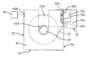
- FIG. 4A is a perspective view of a case used by the carrier tape processing apparatus according to the embodiment of the present disclosure when manufacturing a roll body in a case.
- FIG. 4B is a partially enlarged view of a case used by the carrier tape processing apparatus according to the embodiment of the present disclosure when manufacturing a roll body in a case.
- FIG. 4A is a perspective view of a case used by the carrier tape processing apparatus according to the embodiment of the present disclosure when manufacturing a roll body in a case.
- FIG. 4B is a partially enlarged view of a case used by the carrier tape processing apparatus according to the embodiment of the present disclosure when manufacturing a roll body in
- FIG. 5A is a perspective view of a roll body in a case manufactured by the carrier tape processing apparatus according to the embodiment of the present disclosure.
- FIG. 5B is a partially enlarged view of the cased roll body manufactured by the carrier tape processing apparatus according to the embodiment of the present disclosure.
- FIG. 6A is a diagram showing a usage pattern of a cased roll body manufactured by the carrier tape processing apparatus according to the embodiment of the present disclosure.
- FIG. 6B is a diagram showing a usage pattern of a rolled body in a case manufactured by the carrier tape treatment device according to the embodiment of the present disclosure.
- FIG. 6C is a diagram showing a usage mode of the cased roll body manufactured by the carrier tape processing apparatus according to the embodiment of the present disclosure.
- FIG. 7 is a side view of the carrier tape processing apparatus according to the embodiment of the present disclosure.
- FIG. 8 is an operation explanatory view of the carrier tape processing apparatus according to the embodiment of the present disclosure.
- FIG. 9 is an operation explanatory view of the carrier tape processing apparatus according to the embodiment of the present disclosure.
- FIG. 10 is an operation explanatory view of the carrier tape processing apparatus according to the embodiment of the present disclosure.
- FIG. 11 is an operation explanatory view of the carrier tape processing apparatus according to the embodiment of the present disclosure.
- FIG. 12 is an operation explanatory view of the carrier tape processing apparatus according to the embodiment of the present disclosure.
- FIG. 13 is an operation explanatory view of the carrier tape processing apparatus according to the embodiment of the present disclosure.
- FIG. 14A is an operation explanatory view of the carrier tape processing apparatus according to the embodiment of the present disclosure.
- FIG. 14B is an operation explanatory view of the carrier tape processing apparatus according to the embodiment of the present disclosure.
- FIG. 15 is an operation explanatory view of the carrier tape processing apparatus according to the embodiment of the present disclosure.
- FIG. 16 is a perspective view of a storage warehouse according to an embodiment of the present disclosure.
- FIG. 17 is a block diagram showing a control system of the component mounting system according to the embodiment of the present disclosure.
- FIG. 18 is a flowchart showing a work flow of manufacturing a roll body in a case by the carrier tape processing apparatus according to the embodiment of the present disclosure.
- FIG. 19 is a flowchart showing a work flow of storing the rolled body in a case by the storage warehouse according to the embodiment of the present disclosure.
- FIG. 20 is a diagram showing an image of operation of the cased roll body according to the embodiment of the present disclosure.
- Patent Document 1 has a problem that a large-scale device (parts replenishment means) for supplying a roll of carrier tape to a parts supply unit is required, which is costly.
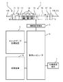
- FIG. 1 shows a configuration diagram of a component mounting system 1 including a carrier tape processing device according to an embodiment of the present disclosure.
- the component mounting system 1 includes a production line 2, a carrier tape processing device 3 related to the supply of parts supplied to the production line 2, and a storage warehouse 4 related to the storage and management of parts.
- the production line 2 manufactures a mounting board JK in which components are mounted on the board KB by performing work while passing the KB between a plurality of devices connected in series.
- the production line 2 is connected to the management computer 6 through the information management terminal 5.
- the management computer 6 manages the operation of each device constituting the production line 2.
- the carrier tape processing device 3 and the storage warehouse 4 are also connected to the management computer 6.
- the management computer 6 also manages the operations of the carrier tape processing device 3 and the storage warehouse 4.
- a worker terminal 7 is connected to the management computer 6, and the worker of the component mounting system 1 inputs various operations from the worker terminal 7 to the component mounting system 1. You can do it.
- the production line 2 includes a board supply device 11, a printing device 12, a post-printing inspection device 13, a plurality of component mounting devices 14, a post-mounting inspection device 15, a reflow device 16, a final inspection device 17, and a board recovery device 18. It has.
- the board supply device 11 sequentially supplies the board KB to the printing device 12 on the downstream side.
- the printing device 12 carries in the board KB supplied from the board supply device 11, applies paste-like solder to the electrodes formed on the surface of the board KB, and carries it out to the post-printing inspection device 13 on the downstream side.
- the post-printing inspection device 13 carries in the substrate KB carried out from the printing device 12, observes with a camera whether or not there are any defective solder coating states, and then inspects the parts mounting device 14 on the downstream side. Carry out the board KB.
- Each component mounting device 14 mounts components on the board KB carried in from the upstream side and carries them out to the downstream side.
- the component mounting device 14 located on the most downstream side carries out the board KB to the post-mounting inspection device 15 located on the downstream side thereof.
- the component mounting device 14 will be described later.
- the post-mounting inspection device 15 carries in the board KB carried out from the component mounting device 14 located on the most downstream side, observes with a camera whether or not there is a defective mounting state of the component, and then inspects the board KB.
- the substrate KB is carried out to the reflow device 16 on the downstream side.
- the reflow device 16 carries in the substrate KB carried out from the inspection device 15 and passes it through a reflow furnace to melt and solidify the solder and join the parts to the electrodes.
- the final inspection device 17 carries in the substrate KB that has passed through the reflow device 16, observes and inspects the bonding state of the parts to the electrodes with a camera, and then carries it out to the substrate recovery device 18 on the downstream side.
- the substrate recovery device 18 receives and recovers the substrate KB carried out from the final inspection device 17.
- a base cover 22 is provided on the base 21 of the component mounting device 14, and the board KB is horizontally conveyed to the work space 23 between the base 21 and the base cover 22.
- a board transport path 24 is provided.
- Feeder carriages 25 are connected to positions on both sides of the substrate transport path 24 on the base 21.
- a plurality of component supply units 26 are attached to each feeder carriage 25.
- the component supply unit 26 is a tape feeder, and by transporting the carrier tape 27 by the sprocket 26S, the component BHs are supplied one by one to a predetermined component supply position.
- a mounting head 32 that is moved in the horizontal plane by the head moving mechanism 31 is provided in the work space 23.
- the mounting head 32 is provided with a component suction nozzle 33 extending downward.
- the component BH supplied by the component supply unit 26 is adsorbed on the lower end of the component suction nozzle 33.
- each component mounting device 14 causes the mounting head 32 to repeatedly perform the mounting turn while supplying the component BH by the component supply unit 26.
- the mounting head 32 sucks and picks up the component BH supplied by the component supply unit 26 in one mounting turn, and mounts the component BH at a predetermined component mounting position on the board KB in this order. conduct.
- the board transport path 24 is operated to carry the board KB to the downstream side.
- the carrier tape 27 used by the component mounting device 14 to supply the component BH is fed out from the roll body 41 in the case in the present embodiment.
- the “cased roll body 41” refers to a roll body 27R in which the carrier tape 27 is rolled into a roll shape and is housed in the case 42 (see also FIG. 3).
- the roll body 41 in the case is different from the roll body with a reel that is conventionally used.
- the "roll body with a reel” means a roll body 27R held by a reel.
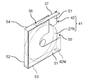
- the case 42 of the roll body 41 in the case will be described.
- the case 42 includes left and right side walls 51, a bottom wall 52, a front wall 53, and a rear wall 54, and has an upper opening 55 and a rear opening 56.
- a wireless tag 42M is attached to the outer surface of the front wall 53.
- Two upper and lower protrusion bases 51B projecting inward from the inner surface of one side wall 51 are provided on the upper portion of the rear wall 54, and the two protrusion bases 51B project outward in the horizontal direction.
- a tape tip holding portion 42K is provided (FIG. 4B).
- the side wall 51 on which the protrusion base 51B is provided is provided with a cutout portion 42D in which a portion sandwiched between the two protrusion bases 51B is cut off.
- the left and right side walls 51 of the case 42 are provided with groove portions 51M extending in a U shape from the edge portion on the upper opening 55 side toward the central portion side of each side wall 51.
- the feed hole 27K (the hole that engages with the outer peripheral teeth of the sprocket 26S) of the carrier tape 27 is inserted into the case 42.
- the provided tape tip holding portion 42K is inserted and locked.
- the cased roll body 41 is being stored or transported when the roll body 27R is stored in the case 42 and the carrier tape 27 is not pulled out from the roll body 27R for use.
- the two tape tip holding portions 42K provided in the case 42 are inserted into the two feed holes 27K and locked. As a result, the carrier tape 27 is prevented from coming off from the case 42 of the roll body 41 in the case during storage or transportation, and the entire roll body 27R is prevented from falling off from the case 42.
- the carrier tape 27 when the carrier tape 27 is pulled out from the cased roll body 41 and used, the two tape tip holding portions 42K are removed from the feed holes 27K of the carrier tape 27, and further, the front wall 53 as shown in FIG.
- the posture should be such that is the bottom surface.
- the carrier tape 27 By pulling out the carrier tape 27 from the rear opening 56 with the front wall 53 facing the lower surface in this way, the carrier tape 27 can be sent to the component supply unit 26.
- the tape tip holding portion 42K in the case 42 By providing the tape tip holding portion 42K in the case 42 in this way, the position of the tip portion of the carrier tape 27 in the case 42 is unified, so that the work of taking out the tip portion of the carrier tape 27 from the case 42 can be easily performed. be able to. Further, it is possible to easily handle the work of taking out the tip portion of the carrier tape 27 by an automated equipment such as a robot.
- Examples of the usage pattern of the cased roll body 41 for the component supply unit 26 include a form of being attached to the feeder carriage 25 as in the cased roll body 41 shown on the left side of FIG. 2, as well as the right side of FIG. 2 and FIG. 6A. Like the cased roll body 41 shown, there is a form of attaching to the component supply unit 26 via the attachment 26A. Alternatively, as shown in FIG. 6B, there is also a form in which the entire roll body 41 in a case is housed inside the component supply unit 26. Alternatively, as shown in FIG. 6C, there is also a form in which the roll body 27R is taken out from the cased roll body 41 and only the roll body 27R is stored inside the component supply unit 26.
- the case 42 of the cased roll body 41 serves as a support means for the roll body 27R when the roll body 27R is installed outside the component supply unit 26 and used (conventional). It can have the role of a reel in a roll body with a reel).
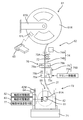
- the carrier tape processing device 3 is a device that processes the carrier tape 27 used in the component mounting device 14 to manufacture the roll body 41 in a case. As shown in FIG. 7, the carrier tape processing device 3 has a carrier tape supply unit 61 for supplying the carrier tape 27 containing the component BH, and a case 42 in which the carrier tape 27 is pulled out from the carrier tape supply unit 61 and rolled into a roll shape. A carrier tape processing unit 62, a handy scanner 63, and a writing unit 64 are provided.
- the carrier tape supply unit 61 includes a reel 61R around which a carrier tape 27 containing a component BH is wound, and a reel support unit 61S that rotatably supports the reel 61R.
- a code label 61L on which information (part information) of the component BH stored in the carrier tape 27 is recorded is attached to the reel 61R.
- An identifier (symbol) such as a barcode or a two-dimensional code is printed on the surface of the code label 61L.
- the carrier tape 27 is wound around the reel 61R in the opposite direction to the normal direction.
- a feed hole 27K appears on the left side, but a reel capable of directly supplying the carrier tape 27 to the parts supply unit 26 (hereinafter referred to as a reel). It appears on the right side in (called a normal reel). This is because the direction of the carrier tape 27 of the roll body 27R created by the roll body creating unit 73, which will be described later, is the same as that of the normal reel.
- the carrier tape processing unit 62 includes a case holding unit 71, a carrier tape feeding unit 72, a roll body creating unit 73, a measuring unit 74, a clamper 75, a cutter 76, and a shaft member extracting unit 77.
- the case holding portion 71 is composed of a conveyor mechanism extending in a horizontal case transport direction (direction perpendicular to the paper surface of FIG. 7).
- the case holding portion 71 holds each of the plurality of cases 42 in a line so that the upper opening 55 faces upward, and intermittently conveys the case 42 in the case conveying direction.
- the carrier tape feed unit 72 performs a feed operation of feeding the carrier tape 27 unwound from the reel 61R of the carrier tape supply unit 61 downward (that is, to the case 42 held by the case holding unit 71).
- the roll body creating unit 73 includes a shaft member 81, a shaft member moving unit 82, and a shaft member driving unit 83.
- the shaft member 81 is rotatably provided around a horizontal axis.
- a chuck portion 81A is provided on the shaft member 81, and the tip portion 27T of the carrier tape 27 can be sandwiched by the chuck portion 81A (FIGS. 8 ⁇ 9).
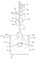
- the shaft member moving portion 82 has a shaft member 81 in which the tip portion 27T of the carrier tape 27 is sandwiched by the chuck portion 81A at a position above the case 42 (FIG. 9) and a position within the groove portion 51M of the case 42 (“inside the case”). It is referred to as "position” and has a function of moving to and from FIG. 10).
- the shaft member driving unit 83 rotates the shaft member 81 in a state where the shaft member 81 is moved to the position inside the case by the shaft member moving unit 82 (arrow R shown in FIG. 11). As a result, the carrier tape 27 is wound around the shaft member 81.
- the roll body creating portion 73 has a shaft member 81 that holds the tip portion 27T of the carrier tape 27, and by rotating the shaft member 81, the carrier tape 27 is wound around the shaft member 81 to form a roll-shaped roll body. It is configured to create 27R.
- the measuring unit 74 includes a length sensor 74A and a component counter 74B.
- the length sensor 74A measures the length of the carrier tape 27 pulled out from the carrier tape supply unit 61 by the carrier tape feed unit 72 based on the amount of movement of the carrier tape feed unit 72.
- the carrier tape feeding unit 72 includes a sprocket 72A for feeding out the carrier tape 27, and the length sensor 74A detects the amount of rotation of the sprocket 72A with an encoder or the like and measures the length of the pulled out carrier tape 27.
- the component counter 74B is located below the length sensor 74A and counts the number of component BHs pulled out from the carrier tape supply unit 61.
- the clamper 75 is provided below the component counter 74B.
- the clamper 75 includes a pair of clamp members 75b and 75c on the base portion 75a. By moving the pair of clamp members 75b and 75c so as to be close to each other, the carrier tape 27 located between the pair of clamp members 75b and 75c is clamped (FIGS. 11 ⁇ 12).
- the cutter 76 is provided between the component counter 74B and the clamper 75, and the two cutting members 76a and 76b are arranged so that the blade surfaces face each other.
- the carrier tape 27 extends downward between the two cutting members 76a and 76b and is clamped by the clamper 75 (FIG. 12). ⁇ Fig. 13).
- the base portion 75a of the clamper 75 (that is, the entire clamper 75) is at the end of the carrier tape 27 opposite to the tip 27T by the two clamp members 75b, 75c after the cutter 76 cuts the carrier tape 27.
- a certain cut end portion 27E (FIG. 14A) is moved by the clamper moving portion 75K (FIG. 7) while being clamped.
- the clamp member 75b enters the notch 42D provided in the case 42 (FIG. 14A ⁇ 14B)
- the cut end portion 27E of the carrier tape 27 is brought into the tape tip holding portion 42K provided in the case 42.
- Set (fix) (Fig. 14B; see also Fig. 5B).
- the base portion 75a of the clamper 75 is horizontally moved in the direction away from the case 42 to pull out the clamp member 75b from the notch portion 42D, and then the base portion 75a is pulled out. Is moved (retracted) above the case 42 (FIG. 14B ⁇ FIG. 15). As a result, the roll body 27R of the carrier tape 27 is formed in the case 42.
- the clamper 75 and the clamper moving portion 75K are provided with an end portion (cut end portion 27E) opposite to the tip portion 27T of the carrier tape 27 cut by the cutter 76 in the case 42.
- the carrier tape end setting portion 75S is set in the tape tip holding portion 42K.
- the shaft member extraction unit 77 extracts the shaft member 81 from the roll body 27R created by the roll body creation unit 73.
- the shaft member extraction unit 77 includes a mechanism for moving the shaft member 81 in the thickness direction of the created roll body 27R.
- the shaft member extraction portion 77 moves the shaft member 81 in the thickness direction of the roll body 27R, the roll body 27R is hindered by the side wall 51 of the case 42, so that the shaft member 81 is pulled out from the roll body 27R.
- the roll body 27R created by the roll body creating unit 73 is stored in the case 42.
- the handy scanner 63 is a device that optically reads an identifier such as a barcode.
- the handy scanner 63 is operated by an operator to read component information from the identifier of the code label 61L affixed to the reel 61R of the carrier tape supply unit 61.
- the "part information" is information about the part BH stored in the carrier tape 27 wound around the reel 61R of the carrier tape supply unit 61, and is the type, part name, characteristic, and date of manufacture of the part BH. It suffices to include at least one of the date, manufacturer, expiration date, number of parts, and access information (URL, etc.) for accessing this information.
- the handy scanner 63 is a part information acquisition unit that acquires part information which is information about the parts stored in the carrier tape 27.
- the component information acquisition unit uses a non-contact reader having a function of non-contactly reading the information recorded on the wireless tag instead of the handy scanner 63. May be used as.
- the writing unit 64 writes information to the wireless tag 42M of the case 42 held by the case holding unit 71 by wireless communication.
- the information written by the writing unit 64 to the wireless tag 42M is the component information acquired (read) through the handy scanner 63 and the identification information.
- the "identification information” is information used to identify the component BH stored in one roll body 27R used in the component mounting system 1 from the component BH housed in the other roll body 27R.
- the identification information is composed of, for example, a serial number issued in the factory where the component mounting system 1 is installed.
- the identification information is generated (issued) by the management computer 6 when the roll body 27R of the carrier tape 27 is generated, as will be described later.
- the identification information is also used as management information for managing the case 42. That is, the identification information is used for both the purpose of identifying the roll body 27R and the purpose of identifying the case 42.
- the storage warehouse 4 stores the roll body 41 in a case.
- the cased roll body 41 referred to here is not only the cased roll body 41 that has just been manufactured by the carrier tape processing device 3, but also the cased roll body 41 that has been used in the component mounting device 14 and has been returned in the middle of use.
- the roll body 41 is also included.
- the storage warehouse 4 has a plurality of shelves 92 (storage units) in the housing 91.
- An inlet 93 is provided below the front surface of the housing 91, and inside the housing 91, an operation of projecting the housing 91 to the outside (front side of the worker OP) through the inlet 93 and the housing 91.
- a moving table 94 is provided to perform a pulling operation to the inside (the back side seen from the worker OP).
- the moving table 94 is projected toward the front side of the worker OP, and the cased roll body 41 placed on the moving table 94 is placed in the housing 91. When it is housed in, it is pulled to the back side.
- Each of the plurality of shelves 92 provided in the storage warehouse 4 is predetermined with a plurality of storage positions 92S for storing (placeting) the roll body 41 in the case. That is, in the present embodiment, each shelf portion 92 is a storage unit provided with a plurality of storage positions 92S for storing the case 42 (that is, the roll body 41 in the case) containing the roll body 27R.
- a case transfer mechanism 95 is provided in the housing 91.
- the case transfer mechanism 95 is vertically extended by a Z-axis table 96 extending in the vertical direction (in the Z-axis direction) and a Z-axis table 96 extending in the front-rear direction (in the Y-axis direction) as seen from the operator OP.
- It includes a transfer head 99 that is moved in the axial direction.
- the Z-axis table 96 moves the Y-axis table 97 in the Z-axis direction
- the Y-axis table 97 moves the X-axis table 98 in the Y-axis direction
- the X-axis table 98 moves the transfer head.
- the transfer head 99 is moved three-dimensionally.
- the transfer head 99 includes two fingers 99F arranged in the X-axis direction.
- the phase head 99 can bring the two fingers 99F close to or separated from each other in the X-axis direction.
- the cased rolls 41 are gripped by the two fingers 99F (ie, by the transfer head 99). NS.
- the transfer head 99 is provided with a non-contact reader 100 whose imaging field of view is directed toward the back as viewed from the operator OP.
- the non-contact reader 100 faces the wireless tag 42M provided on the case 42 of the cased roll body 41 at the position where the transfer head 99 grips the cased roll body 41.
- the non-contact reader 100 reads the information written in the wireless tag 42M (part information and identification information of the component BH stored in the roll body 27R) by wireless communication in a state of facing the wireless tag 42M.
- the non-contact reader 100 functions as an identification information reading means for reading the identification information written in the wireless tag 42M as a storage unit.
- the non-contact reader 100 stores the read information in the management computer 6 (described later).
- a unique address is given to each storage position 92S defined for each of the plurality of shelves 92.
- the information (part information) of the part BH stored in the roll body 27R (carrier tape 27) of the cased roll body 41 is used.
- the identification information of the cased roll body 41 are stored in the management computer 6 (so-called associative information).
- information relating the component information and the information (storage position information) of the storage position 92S is stored in the management computer 6 (described later).
- the management computer 6 can grasp which storage position 92S of the storage warehouse 4 stores the cased roll body 41 in which the component BH is stored.
- FIG. 17 shows a block diagram of the control system in the entire component mounting system 1.
- the management computer 6 includes a production information management unit 101, a parts monitoring unit 102, a work instruction unit 103, and an information management unit 104.
- the production information management unit 101 stores the production plan data in the component mounting system 1.
- the component monitoring unit 102 monitors the remaining number of component BHs on the production line 2. When the component monitoring unit 102 is predicted to be out of parts, the component monitoring unit 102 notifies the work instruction unit 103 to that effect.
- the work instruction unit 103 issues work instructions for switching models based on the production planning data stored in the production information management unit 101 to the production line 2 and the worker OP, and is used in the production of the next model. Instructions such as withdrawal of parts BH to be performed are given to the storage warehouse 4. Further, the work instruction unit 103 issues a work instruction based on the information from the parts monitoring unit 102 (specifically, an instruction to pay out the replenishment parts to the storage warehouse 4 and an instruction to replenish the parts to the worker OP). ..
- the information management unit 104 includes a first information management unit 104a, a second information management unit 104b, an identification information generation unit 104c, and a storage position information generation unit 104d (FIG. 17).
- the first information management unit 104a manages the part information
- the second information management unit 104b manages the information (storage position information) of the storage position 92S of the part BH in the storage warehouse 4.
- the first information management unit 104a stores the generated roll body 27R in a state in which the component information and the identification information are associated with each other.
- the second information management unit 104b stores the generated identification information about the roll body 27R and the information (storage position information) of the storage position 92S in a state of being associated with each other.
- the identification information generation unit 104c generates (issues) identification information about the roll body 27R when the shaft member extraction unit 77 pulls out the shaft member 81 from the roll body 27R in the carrier tape processing device 3.
- the storage position information generation unit 104d specifies the storage position 92S of the cased roll body 41 and generates the storage position information.
- the carrier tape processing device 3 includes a processing device control unit 3C.
- the processing device control unit 3C includes a carrier tape processing unit 62 (case holding unit 71, carrier tape feeding unit 72, shaft member moving unit 82 of roll body creating unit 73, shaft member driving unit 83, and measuring unit) included in the carrier tape processing device 3. It controls 74 (length sensor 74A, component counter 74B), clamper 75, clamper moving unit 75K, cutter 76, shaft member extraction unit 77), handy scanner 63, and writing unit 64.
- the storage warehouse 4 includes a warehouse control unit 4C.
- the warehouse control unit 4C controls the moving table 94, the case transfer mechanism 95, and the non-contact reader 100 included in the storage warehouse 4.
- the processing device control unit 3C of the carrier tape processing device 3 acquires the part information of the carrier tape 27 wound around the reel 61R of the carrier tape supply unit 61 (part information acquisition step in step ST1).
- the component information is acquired by the operator OP reading the identifier of the code label 61L affixed to the reel 61R of the carrier tape supply unit 61 with the handy scanner 63 (FIG. 7), but another method. May be.
- the worker OP may input the contents of the code label 61L from an input device (not shown) connected to the processing device control unit 3C.
- the processing device control unit 3C After acquiring the component information of the carrier tape 27 wound around the reel 61R of the carrier tape supply unit 61 in step ST1, the processing device control unit 3C operates the case holding unit 71 to store the roll body 27R from now on.
- the case 42 empty case 42
- the processing device control unit 3C operates the shaft member moving unit 82 to be above the empty case 42 (that is, at the working position) held by the case holding unit 71.
- the shaft member 81 is moved to a predetermined position (step ST3, the shaft member upward movement step. FIG. 8).
- the processing device control unit 3C moves the shaft member 81 to a predetermined position above the case 42 in step ST3
- the carrier tape 27 is moved by the carrier tape feed unit 72 while rotating the reel 61R to feed the carrier tape 27 downward. Is fed downward to hold the tip portion 27T of the carrier tape 27 on the shaft member 81 (tape holding step in step ST4).
- the tip portion 27T of the carrier tape 27 is gripped by a robot or the like (not shown), and then the tip portion 27T of the carrier tape 27 is inserted between the shaft member 81 and the chuck portion 81A. Then, by operating the chuck portion 81A after that, the tip portion 27T of the carrier tape 27 is sandwiched between the shaft member 81 and the chuck portion 81A (FIGS. 9 ⁇ 10).
- Step ST5 the step of moving the shaft member downward. FIG. 10
- the processing device control unit 3C positions the shaft member 81 in the case
- the carrier tape feeding unit While the carrier tape 27 is pulled downward from the carrier tape supply unit 61 by 72 (carrier tape pulling step in step ST6), the carrier tape 27 is brought to the shaft member 81 by rotating the shaft member 81 by the shaft member driving unit 83.
- a roll-shaped roll body 27R is made by winding the roll body 27R (roll body making step in step ST7. FIG. 11).
- the processing device control unit 3C constitutes the measuring unit 74 after rotating the shaft member 81 and starting to wind the carrier tape 27 around the shaft member 81.
- the length sensor 74A measures the length of the carrier tape 27 pulled out (or the number of the pulled-out parts BH is measured by the part counter 74B constituting the measuring unit 74). Then, the processing device control unit 3C has reached a predetermined length of the carrier tape 27 drawn from the carrier tape supply unit 61 (or the component BH drawn from the carrier tape supply unit 61). When the number of the shaft members 81 reaches a predetermined number), the rotation of the shaft member 81 is stopped.
- the processing device control unit 3C clamps the carrier tape 27 with the clamper 75 (clamping step in step ST8. FIG. 11 ⁇ FIG. 12). Then, the cutter 76 is operated to cut the carrier tape 27 (cutting step of step ST9. FIG. 12 ⁇ FIG. 13).
- the processing device control unit 3C of the carrier tape processing device 3 cuts when the measuring unit 74 measures the length of the carrier tape 27 specified in advance or the number of parts BH specified in advance. It functions as a cutting control unit that causes the cutter 76 as a unit to cut the carrier tape 27.
- the processing device control unit 3C causes the cutter 76 to cut the carrier tape 27 when the length sensor 74A measures the length of the carrier tape 27 designated in advance.
- the cutter 76 may cut the carrier tape 27 when the 74B measures the number of pre-designated parts.
- the processing device control unit 3C When the processing device control unit 3C operates the cutter 76 to cut the carrier tape 27, the processing device control unit 3C operates the clamper moving unit 75K to cut the cut end portion 27E of the carrier tape 27 cut by the cutter 76 into the case 42 in the same manner as described above. It is fixed to the tape tip holding portion 42K provided in (step ST10, tape fixing step. FIG. 14A ⁇ FIG. 14B).
- the processing device control unit 3C moves the base portion 75a of the clamper 75 upward (FIG. 15) and operates the shaft member moving portion 82. Then, the shaft member 81 is pulled out from the case 42 (from the roll body 27R). As a result, the roll body 27R created by winding the carrier tape 27 around the shaft member 81 is stored in the case 42 (roll body storage step in step ST11). By this roll body storage process, one roll body 27R is stored in one empty case 42.
- step ST7 the carrier tape 27 pulled out in the carrier tape pulling-out step is rolled and stored in the case 42. It is a tape processing process.
- the processing device control unit 3C When the shaft member 81 is pulled out from the case 42 in step ST11, the processing device control unit 3C requests the identification information generation unit 104c of the management computer 6 to generate identification information about the roll body 27R in the case 42. Then, the identification information generation unit 104c requested to generate the identification information by the processing device control unit 3C generates the identification information about the roll body 27R in the case 42 (identification information generation step in step ST12).
- the processing device control unit 3C receives the generated identification information. Then, the writing unit 64 writes the component information acquired in step ST1 and the identification information generated in step ST12 to the wireless tag 42M attached to the case 42 (case 42 in which the roll body 27R is housed). (Writing step of step ST13).
- the processing device control unit 3C writes the part information and the identification information to the wireless tag 42M of the case 42, and then transmits the information written to the wireless tag 42M (part information and identification information about the roll body 27R) to the management computer 6.
- the information (part information and identification information) is stored in the first information management unit 104a of the management computer 6.
- the management computer is associated with the identification information which is the unique information of the roll body 27R and the part information which is the information of the part BH stored in the roll body 27R. It is registered in 6 (part information registration step in step ST14).
- the processing device control unit 3C When the processing device control unit 3C writes the information about the roll body 27R to the first information management unit 104a of the management computer 6, it determines whether or not all the cased roll bodies 41 to be manufactured have been manufactured (step ST15). End judgment process). Then, when it is determined that all the cased rolls 41 have not been manufactured yet, it is determined that the process returns to step ST2 to newly manufacture the cased rolls 41 and all the cased rolls 41 have been manufactured. In this case, the production of the roll body 41 in the case (processing work of the carrier tape 27) by the carrier tape processing device 3 is completed.
- the warehouse control unit 4C of the storage warehouse 4 moves the moving table 94 toward the front side from the entrance 93 provided in the housing 91.
- the worker OP or a mobile robot (not shown) places the cased roll body 41 on the moving table 94 (placement step of step ST21; FIG. 19).
- the roll body 41 in the case is placed on the moving table 94 in a posture in which the upper opening 55 faces upward and the front wall 53 faces the front side (the side of the worker OP).
- the wireless tag 42M provided on the case 42 is in a state of facing the front side (FIG. 16).
- the warehouse control unit 4C When the cased roll body 41 is placed on the moving table 94, the warehouse control unit 4C operates the moving table 94 to pull the cased roll body 41 into the housing 91. When the cased roll body 41 is pulled into the housing 91, the warehouse control unit 4C moves the transfer head 99 to the front side of the cased roll body 41 placed on the moving table 94. Then, the two fingers 99F are operated so as to close, and the transfer head 99 is made to grip the roll body 41 in the case. At this time, the non-contact reader 100 provided in the transfer head 99 faces the wireless tag 42M provided in the case 42 of the roll body 41 in the case, and the non-contact reader 100 reads the identification information written in the wireless tag 42M. (Step of reading identification information in step ST22).
- the warehouse control unit 4C transmits the identification information read by the non-contact reader 100 to the management computer 6. Then, the management computer 6 that receives the identification information from the warehouse control unit 4C receives the identification information from the storage position information generation unit 104d in the cased roll body 41 (the case where the non-contact reader 100 reads the identification information) corresponding to the identification information.
- the storage position 92S in the storage warehouse 4 of the roll body 41) is specified and the storage position information is generated (the storage position information generation step in step ST23).
- the storage position 92S is specified by arbitrarily selecting from the storage positions 92S that are vacant at that time or according to a predetermined rule.
- the management computer 6 associates the generated storage position information with the identification information of the cased roll 41 corresponding to the storage position information. In this state, it is stored in the second information management unit 104b.
- the identification information that is unique information of the roll body 27R and the storage of the cased roll body 41 including the roll body 27R in the storage warehouse 4 It is registered in the management computer 6 in a state associated with the position information (storage position information) (storage position information registration step in step ST24).
- the management computer 6 stores the storage information and the identification information of the cased roll body 41 placed on the moving table 94 in the second information management unit 104b in a state of being associated with each other. Then, the management computer 6 operates the case transfer mechanism 95 to transfer and store the cased roll body 41 placed on the moving table 94 to the storage position 92S corresponding to the storage position information (step ST25). Storage process). As a result, the storage work of the roll body 41 in the case is completed.
- the roll body 27R in which the carrier tape 27 pulled out from the reel 61R of the carrier tape supply unit 61 is rolled is stored in the case 42, so that the roll body 27R is stored in the case 42. It can be treated as.
- the roll body 41 in the case can be made more compact by making the dimension in the width direction smaller than that of the roll body with a reel, and the reel does not remain as waste after the roll body 27R (that is, the carrier tape 27) is used up. So workability is also good.
- the case 42 is not only inexpensive in itself, but can be reused (reused) unlike the reel, so that the cost can be reduced in that respect as well.
- the case 42 is provided with a wireless tag 42M as a storage unit capable of storing component information, and the component information of the carrier tape 27 wound around the reel 61R is transmitted to the wireless tag 42M. Can be written and memorized. Further, since the component information and the identification information which is the unique information of the roll body 27R can be associated and stored, the component information can be managed in each unit of the cased roll body 41.
- the carrier tape processing device 3 has a processing device control unit 3C, a carrier tape processing unit 62, a handy scanner 63 as a component information reading unit, a writing unit 64, and a storage warehouse 4 (warehouse control unit 4C, shelf).
- the generation unit 104d) constitutes the parts management device 110 (FIG. 17).
- part information is acquired (part information acquisition process), identification information is generated (identification information generation process), and then these part information
- the identification information is written in the wireless tag 42M provided in the case 42 (writing step), and the written component information and the identification information are associated with each other and stored in the first information management unit 104a (part information registration step).
- the identification information written in the wireless tag 42M is read by the identification information reading unit (non-contact reader 100) (identification information reading step), the storage position 92S is specified, and the storage position information is generated (storage position information generation).
- the identification information and the storage position information are associated with each other and stored in the second information management unit 104b (storage position information registration step).
- the parts information and the identification information of the cased roll body 41 are stored in association with each other, and the identification information of the cased roll body 41 and the storage position information are stored in association with each other.
- the cased roll 41 can be smoothly stored and taken out in the storage warehouse 4. Therefore, according to the parts management device 110 (parts management method) in the present embodiment, the warehousing and warehousing of the parts BH can be easily and efficiently performed.
- FIG. 20 illustrates an image of the operation of the cased roll body 41 in the component mounting system 1 according to the present embodiment.
- the cased roll body 41 according to the present embodiment is manufactured by supplying the reel 61R around which the carrier tape 27 is wound and the case 42 to the carrier tape processing device 3.
- a part of the cased roll body 41 manufactured by the carrier tape processing device 3 is sent to the production line 2 for use, and the other part is stored (stored) in the storage warehouse 4.
- the cased roll body 41 stored in the storage warehouse 4 is delivered from there and sent to the production line 2 for use.
- case 42 generated by the carrier tape 27 of the cased roll body 41 being used up in the production line 2 is collected and supplied to the carrier tape processing device 3 and reused for manufacturing a new cased roll body 41.
- a part of the cased roll body 41 sent to the production line 2 in a state where the carrier tape 27 has not been used up is returned to the storage warehouse 4 and stored (stocked).
- the roll body 27R obtained by rolling the carrier tape 27 drawn from the reel 61R of the carrier tape supply unit 61 into a roll shape is used as the case 42.
- the roll body 27R can be handled as a roll body 41 in a case.
- the roll body 41 in the case can be made more compact by making the dimension in the width direction smaller than that of the roll body with a reel, and the reel does not remain as waste after the roll body 27R (that is, the carrier tape 27) is used up. So workability is also good.
- the case 42 is not only inexpensive in itself, but can be reused (reused) unlike a reel, so that the cost can be reduced in that respect as well. Therefore, according to the carrier tape processing device 3 (carrier tape processing method) in the present embodiment, it is possible to realize a reelless component supply form with an inexpensive configuration.
- the present disclosure is not limited to the above-mentioned ones, and various modifications and the like are possible.
- the specific configuration of the carrier tape processing unit 62 shown in the above-described embodiment is merely an example, and if the carrier tape 27 can be pulled out from the carrier tape supply unit 61, rolled, and stored in the case 42. Its composition is free.
- the reel 61R a reel in which the carrier tape 27 is wound from a commonly distributed ordinary reel may be used. In this case, the handy scanner 63 reads the part information from the identifier of the normal reel, not from the reel 61R.
- Carrier tape processing device 3C Processing device control unit (cutting control unit) 27 Carrier tape 27T Tip 27E Cut end (opposite end) 27R Roll body 41 Roll body with case 42 Case 61 Carrier tape supply part 62 Carrier tape processing part 64 Writing part 73 Roll body making part 74 Measuring part 75S Carrier tape end setting part 76 Cutter (cutting part) 77 Shaft member extraction unit 81 Shaft member 104 Information management unit 104a First information management unit 104b Second information management unit 104c Identification information generation unit BH parts
Abstract
Unité d'acheminement de ruban porteur qui achemine un ruban porteur stockant des pièces; et unité de traitement de ruban porteur qui retire le ruban porteur de l'unité d'acheminement de ruban porteur, met le ruban porteur en une forme de rouleau, et stocke celui-ci dans un boîtier. En outre, l'unité de traitement de ruban porteur comprend : une unité de formation de corps de rouleau qui comporte un élément arbre pour retenir la section d'extrémité avant du ruban porteur, et qui fait tourner l'élément arbre de telle sorte que le ruban porteur est enroulé autour de l'élément arbre, formant de ce fait un corps de rouleau en forme de rouleau; et une unité d'extraction d'élément arbre qui extrait l'élément arbre du corps de rouleau formé par l'unité de formation de corps de rouleau.
Priority Applications (4)
| Application Number | Priority Date | Filing Date | Title |
|---|---|---|---|
| JP2021535617A JP7178566B2 (ja) | 2020-03-25 | 2021-01-21 | キャリアテープ処理装置およびキャリアテープ処理方法 |
| US17/905,638 US20230114831A1 (en) | 2020-03-25 | 2021-01-21 | Carrier-tape processing device and carrier-tape processing method |
| DE112021001830.2T DE112021001830T5 (de) | 2020-03-25 | 2021-01-21 | Carrier-Tape-Verarbeitungsvorrichtung und Carrier-Tape-Verarbeitungsverfahren |
| CN202180017847.9A CN115211249A (zh) | 2020-03-25 | 2021-01-21 | 载带处理装置及载带处理方法 |
Applications Claiming Priority (2)
| Application Number | Priority Date | Filing Date | Title |
|---|---|---|---|
| JP2020-053535 | 2020-03-25 | ||
| JP2020053535 | 2020-03-25 |
Publications (1)
| Publication Number | Publication Date |
|---|---|
| WO2021192558A1 true WO2021192558A1 (fr) | 2021-09-30 |
Family
ID=77890109
Family Applications (1)
| Application Number | Title | Priority Date | Filing Date |
|---|---|---|---|
| PCT/JP2021/001958 WO2021192558A1 (fr) | 2020-03-25 | 2021-01-21 | Dispositif de traitement de ruban porteur et procédé de traitement de ruban porteur |
Country Status (5)
| Country | Link |
|---|---|
| US (1) | US20230114831A1 (fr) |
| JP (2) | JP7178566B2 (fr) |
| CN (1) | CN115211249A (fr) |
| DE (1) | DE112021001830T5 (fr) |
| WO (1) | WO2021192558A1 (fr) |
Citations (5)
| Publication number | Priority date | Publication date | Assignee | Title |
|---|---|---|---|---|
| JPH04173584A (ja) * | 1990-10-24 | 1992-06-22 | Murata Mfg Co Ltd | チップ状電子部品のためのパッケージ |
| JPH0521990A (ja) * | 1991-07-17 | 1993-01-29 | Matsushita Electric Ind Co Ltd | 電子部品集合体および電子部品集合体の供給装置 |
| JP2005119880A (ja) * | 2004-10-14 | 2005-05-12 | Shin Etsu Polymer Co Ltd | テープ巻取装置 |
| JP2006114764A (ja) * | 2004-10-15 | 2006-04-27 | Murata Mfg Co Ltd | パッケージ電子部品および電子部品マウンタ |
| WO2020202737A1 (fr) * | 2019-03-29 | 2020-10-08 | パナソニックIpマネジメント株式会社 | Dispositif de maintien de bande de support, support et corps d'emballage de bande de support |
Family Cites Families (5)
| Publication number | Priority date | Publication date | Assignee | Title |
|---|---|---|---|---|
| JPS5845268Y2 (ja) * | 1976-11-30 | 1983-10-14 | 太陽誘電株式会社 | 電子部品の包装箱 |
| JPS6228377A (ja) * | 1985-07-24 | 1987-02-06 | 株式会社村田製作所 | 電子部品連収納体 |
| KR100899419B1 (ko) | 2004-09-30 | 2009-05-26 | 시바우라 메카트로닉스 가부시키가이샤 | 접착막 테이프 수납용 카세트 교환장치, 접착막 테이프수납용 카세트 및 접착막 첩부장치 |
| JP2006290610A (ja) | 2005-04-15 | 2006-10-26 | Brother Ind Ltd | ラベル用テープロール及びラベル用カートリッジ |
| CN108128667A (zh) | 2016-12-01 | 2018-06-08 | 何政豪 | 具无线射频识别的智能型卷盘 |
-
2021
- 2021-01-21 JP JP2021535617A patent/JP7178566B2/ja active Active
- 2021-01-21 WO PCT/JP2021/001958 patent/WO2021192558A1/fr active Application Filing
- 2021-01-21 DE DE112021001830.2T patent/DE112021001830T5/de active Pending
- 2021-01-21 CN CN202180017847.9A patent/CN115211249A/zh active Pending
- 2021-01-21 US US17/905,638 patent/US20230114831A1/en active Pending
-
2022
- 2022-07-13 JP JP2022112212A patent/JP7349607B2/ja active Active
Patent Citations (5)
| Publication number | Priority date | Publication date | Assignee | Title |
|---|---|---|---|---|
| JPH04173584A (ja) * | 1990-10-24 | 1992-06-22 | Murata Mfg Co Ltd | チップ状電子部品のためのパッケージ |
| JPH0521990A (ja) * | 1991-07-17 | 1993-01-29 | Matsushita Electric Ind Co Ltd | 電子部品集合体および電子部品集合体の供給装置 |
| JP2005119880A (ja) * | 2004-10-14 | 2005-05-12 | Shin Etsu Polymer Co Ltd | テープ巻取装置 |
| JP2006114764A (ja) * | 2004-10-15 | 2006-04-27 | Murata Mfg Co Ltd | パッケージ電子部品および電子部品マウンタ |
| WO2020202737A1 (fr) * | 2019-03-29 | 2020-10-08 | パナソニックIpマネジメント株式会社 | Dispositif de maintien de bande de support, support et corps d'emballage de bande de support |
Also Published As
| Publication number | Publication date |
|---|---|
| CN115211249A (zh) | 2022-10-18 |
| JPWO2021192558A1 (fr) | 2021-09-30 |
| JP7349607B2 (ja) | 2023-09-25 |
| US20230114831A1 (en) | 2023-04-13 |
| JP2022140485A (ja) | 2022-09-26 |
| JP7178566B2 (ja) | 2022-11-28 |
| DE112021001830T5 (de) | 2023-01-05 |
Similar Documents
| Publication | Publication Date | Title |
|---|---|---|
| JP6377752B2 (ja) | 部品実装システム及び部品実装方法 | |
| US11470751B2 (en) | Component-mounting system and management device | |
| JP2007019320A (ja) | 電子回路基板の生産管理方法及び生産管理システム | |
| WO2021192557A1 (fr) | Dispositif de traitement de bande de support et procédé de traitement de bande de support | |
| JP6676482B2 (ja) | 電子部品供給システム | |
| JP2017130593A (ja) | フィーダ自動交換システム | |
| JP2019176188A (ja) | 部品実装システム | |
| JP6684015B2 (ja) | 部品実装システム及び部品実装方法 | |
| JP6694767B2 (ja) | スプライシングユニット及び電子部品供給システム | |
| WO2021192558A1 (fr) | Dispositif de traitement de ruban porteur et procédé de traitement de ruban porteur | |
| WO2021192408A1 (fr) | Dispositif et procédé de gestion de composants | |
| JP6120862B2 (ja) | リール管理システム及びリール管理方法 | |
| WO2021181759A1 (fr) | Dispositif de maintien et système de montage de composants | |
| JP2021153153A (ja) | キャリアテープ処理装置およびキャリアテープ処理方法 | |
| JP6704451B2 (ja) | スプライシングユニット | |
| JP7470907B2 (ja) | 部品実装システムおよびキャリアテープロール体の処理方法 | |
| US20230114399A1 (en) | Component mounting system and method for handling carrier tape roll body | |
| JP2006332090A (ja) | 電子部品実装装置および電子部品実装装置における部品情報管理方法 | |
| JP2021153154A (ja) | 部品実装システムおよびキャリアテープロール体の処理方法 | |
| JP2021153152A (ja) | キャリアテープロール体 | |
| JP7403045B2 (ja) | キャリアテープロール体製造装置およびキャリアテープロール体の製造方法 | |
| WO2023139789A1 (fr) | Dispositif de préparation, dispositif de montage, système de montage et procédé de traitement d'informations | |
| JP6990147B2 (ja) | 部品実装システム | |
| JP2021182626A (ja) | 部品実装システムおよび部品実装方法 | |
| CN116605564A (zh) | 供给架、生产系统、以及供给方法 |
Legal Events
| Date | Code | Title | Description |
|---|---|---|---|
| ENP | Entry into the national phase |
Ref document number: 2021535617 Country of ref document: JP Kind code of ref document: A |
|
| 121 | Ep: the epo has been informed by wipo that ep was designated in this application |
Ref document number: 21774201 Country of ref document: EP Kind code of ref document: A1 |
|
| 122 | Ep: pct application non-entry in european phase |
Ref document number: 21774201 Country of ref document: EP Kind code of ref document: A1 |