WO2021192558A1 - キャリアテープ処理装置およびキャリアテープ処理方法 - Google Patents
キャリアテープ処理装置およびキャリアテープ処理方法 Download PDFInfo
- Publication number
- WO2021192558A1 WO2021192558A1 PCT/JP2021/001958 JP2021001958W WO2021192558A1 WO 2021192558 A1 WO2021192558 A1 WO 2021192558A1 JP 2021001958 W JP2021001958 W JP 2021001958W WO 2021192558 A1 WO2021192558 A1 WO 2021192558A1
- Authority
- WO
- WIPO (PCT)
- Prior art keywords
- carrier tape
- roll body
- unit
- case
- shaft member
- Prior art date
Links
Images


Classifications
-
- H—ELECTRICITY
- H05—ELECTRIC TECHNIQUES NOT OTHERWISE PROVIDED FOR
- H05K—PRINTED CIRCUITS; CASINGS OR CONSTRUCTIONAL DETAILS OF ELECTRIC APPARATUS; MANUFACTURE OF ASSEMBLAGES OF ELECTRICAL COMPONENTS
- H05K13/00—Apparatus or processes specially adapted for manufacturing or adjusting assemblages of electric components
- H05K13/04—Mounting of components, e.g. of leadless components
- H05K13/0417—Feeding with belts or tapes
- H05K13/0419—Feeding with belts or tapes tape feeders
-
- B—PERFORMING OPERATIONS; TRANSPORTING
- B65—CONVEYING; PACKING; STORING; HANDLING THIN OR FILAMENTARY MATERIAL
- B65H—HANDLING THIN OR FILAMENTARY MATERIAL, e.g. SHEETS, WEBS, CABLES
- B65H35/00—Delivering articles from cutting or line-perforating machines; Article or web delivery apparatus incorporating cutting or line-perforating devices, e.g. adhesive tape dispensers
- B65H35/0006—Article or web delivery apparatus incorporating cutting or line-perforating devices
- B65H35/006—Article or web delivery apparatus incorporating cutting or line-perforating devices with means for delivering a predetermined length of tape
- B65H35/0066—Article or web delivery apparatus incorporating cutting or line-perforating devices with means for delivering a predetermined length of tape this length being adjustable
-
- B—PERFORMING OPERATIONS; TRANSPORTING
- B65—CONVEYING; PACKING; STORING; HANDLING THIN OR FILAMENTARY MATERIAL
- B65H—HANDLING THIN OR FILAMENTARY MATERIAL, e.g. SHEETS, WEBS, CABLES
- B65H18/00—Winding webs
- B65H18/08—Web-winding mechanisms
- B65H18/10—Mechanisms in which power is applied to web-roll spindle
-
- B—PERFORMING OPERATIONS; TRANSPORTING
- B65—CONVEYING; PACKING; STORING; HANDLING THIN OR FILAMENTARY MATERIAL
- B65H—HANDLING THIN OR FILAMENTARY MATERIAL, e.g. SHEETS, WEBS, CABLES
- B65H75/00—Storing webs, tapes, or filamentary material, e.g. on reels
- B65H75/02—Cores, formers, supports, or holders for coiled, wound, or folded material, e.g. reels, spindles, bobbins, cop tubes, cans, mandrels or chucks
- B65H75/18—Constructional details
- B65H75/182—Identification means
-
- H—ELECTRICITY
- H05—ELECTRIC TECHNIQUES NOT OTHERWISE PROVIDED FOR
- H05K—PRINTED CIRCUITS; CASINGS OR CONSTRUCTIONAL DETAILS OF ELECTRIC APPARATUS; MANUFACTURE OF ASSEMBLAGES OF ELECTRICAL COMPONENTS
- H05K13/00—Apparatus or processes specially adapted for manufacturing or adjusting assemblages of electric components
- H05K13/08—Monitoring manufacture of assemblages
- H05K13/086—Supply management, e.g. supply of components or of substrates
-
- B—PERFORMING OPERATIONS; TRANSPORTING
- B65—CONVEYING; PACKING; STORING; HANDLING THIN OR FILAMENTARY MATERIAL
- B65H—HANDLING THIN OR FILAMENTARY MATERIAL, e.g. SHEETS, WEBS, CABLES
- B65H2301/00—Handling processes for sheets or webs
- B65H2301/40—Type of handling process
- B65H2301/41—Winding, unwinding
- B65H2301/414—Winding
- B65H2301/4144—Finishing winding process
- B65H2301/41445—Finishing winding process after winding process
- B65H2301/41446—Finishing winding process after winding process removing roll/core from shaft/mandrel, e.g. by compressed air
-
- B—PERFORMING OPERATIONS; TRANSPORTING
- B65—CONVEYING; PACKING; STORING; HANDLING THIN OR FILAMENTARY MATERIAL
- B65H—HANDLING THIN OR FILAMENTARY MATERIAL, e.g. SHEETS, WEBS, CABLES
- B65H2701/00—Handled material; Storage means
- B65H2701/10—Handled articles or webs
- B65H2701/19—Specific article or web
- B65H2701/1942—Web supporting regularly spaced non-adhesive articles
Definitions
- the present disclosure relates to a carrier tape processing apparatus and a carrier tape processing method for processing a carrier tape containing parts.
- a tape feeder that supplies components to a component take-out position by transporting a carrier tape containing the components is known.
- the carrier tape used in the tape feeder is wound around a reel as its holder, and the carrier tape is transported and stored, and the set for the parts supply unit remains wound around the reel (roll body with reel). Will be done).
- Patent Document 1 a device has been proposed that eliminates the reel and enables the carrier tape to be supplied to the component supply unit in the state of a roll wound in a roll shape (for example, Patent Document 1 below).
- the roll body of the carrier tape is put into the storage portion of the parts supply unit from the means for replenishing the parts (parts replenishment means), and is unnecessary after the parts supply unit finishes pulling out the carrier tape. No reels are left on the mounting work site.
- an object of the present disclosure is to provide a carrier tape processing apparatus and a carrier tape processing method capable of realizing a reelless component supply form with an inexpensive configuration.
- the carrier tape processing apparatus of the present disclosure includes a carrier tape supply unit that supplies a carrier tape containing parts, and a carrier tape processing unit that pulls out the carrier tape from the carrier tape supply unit, rolls it, and stores it in a case.
- the carrier tape processing method of the present disclosure includes a carrier tape pull-out step of pulling out a carrier tape from a carrier tape supply unit that supplies a carrier tape containing parts, and a carrier tape pull-out step of pulling out the carrier tape in a carrier tape pull-out step into a case. Includes a carrier tape processing step for storing.
- FIG. 1 is a schematic configuration diagram of a component mounting system according to an embodiment of the present disclosure.
- FIG. 2 is a side view of a component mounting device included in the component mounting system according to the embodiment of the present disclosure.
- FIG. 3 is a perspective view of a roll body in a case used by the component mounting device according to the embodiment of the present disclosure.
- FIG. 4A is a perspective view of a case used by the carrier tape processing apparatus according to the embodiment of the present disclosure when manufacturing a roll body in a case.
- FIG. 4B is a partially enlarged view of a case used by the carrier tape processing apparatus according to the embodiment of the present disclosure when manufacturing a roll body in a case.
- FIG. 4A is a perspective view of a case used by the carrier tape processing apparatus according to the embodiment of the present disclosure when manufacturing a roll body in a case.
- FIG. 4B is a partially enlarged view of a case used by the carrier tape processing apparatus according to the embodiment of the present disclosure when manufacturing a roll body in
- FIG. 5A is a perspective view of a roll body in a case manufactured by the carrier tape processing apparatus according to the embodiment of the present disclosure.
- FIG. 5B is a partially enlarged view of the cased roll body manufactured by the carrier tape processing apparatus according to the embodiment of the present disclosure.
- FIG. 6A is a diagram showing a usage pattern of a cased roll body manufactured by the carrier tape processing apparatus according to the embodiment of the present disclosure.
- FIG. 6B is a diagram showing a usage pattern of a rolled body in a case manufactured by the carrier tape treatment device according to the embodiment of the present disclosure.
- FIG. 6C is a diagram showing a usage mode of the cased roll body manufactured by the carrier tape processing apparatus according to the embodiment of the present disclosure.
- FIG. 7 is a side view of the carrier tape processing apparatus according to the embodiment of the present disclosure.
- FIG. 8 is an operation explanatory view of the carrier tape processing apparatus according to the embodiment of the present disclosure.
- FIG. 9 is an operation explanatory view of the carrier tape processing apparatus according to the embodiment of the present disclosure.
- FIG. 10 is an operation explanatory view of the carrier tape processing apparatus according to the embodiment of the present disclosure.
- FIG. 11 is an operation explanatory view of the carrier tape processing apparatus according to the embodiment of the present disclosure.
- FIG. 12 is an operation explanatory view of the carrier tape processing apparatus according to the embodiment of the present disclosure.
- FIG. 13 is an operation explanatory view of the carrier tape processing apparatus according to the embodiment of the present disclosure.
- FIG. 14A is an operation explanatory view of the carrier tape processing apparatus according to the embodiment of the present disclosure.
- FIG. 14B is an operation explanatory view of the carrier tape processing apparatus according to the embodiment of the present disclosure.
- FIG. 15 is an operation explanatory view of the carrier tape processing apparatus according to the embodiment of the present disclosure.
- FIG. 16 is a perspective view of a storage warehouse according to an embodiment of the present disclosure.
- FIG. 17 is a block diagram showing a control system of the component mounting system according to the embodiment of the present disclosure.
- FIG. 18 is a flowchart showing a work flow of manufacturing a roll body in a case by the carrier tape processing apparatus according to the embodiment of the present disclosure.
- FIG. 19 is a flowchart showing a work flow of storing the rolled body in a case by the storage warehouse according to the embodiment of the present disclosure.
- FIG. 20 is a diagram showing an image of operation of the cased roll body according to the embodiment of the present disclosure.
- Patent Document 1 has a problem that a large-scale device (parts replenishment means) for supplying a roll of carrier tape to a parts supply unit is required, which is costly.
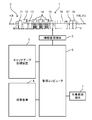
- FIG. 1 shows a configuration diagram of a component mounting system 1 including a carrier tape processing device according to an embodiment of the present disclosure.
- the component mounting system 1 includes a production line 2, a carrier tape processing device 3 related to the supply of parts supplied to the production line 2, and a storage warehouse 4 related to the storage and management of parts.
- the production line 2 manufactures a mounting board JK in which components are mounted on the board KB by performing work while passing the KB between a plurality of devices connected in series.
- the production line 2 is connected to the management computer 6 through the information management terminal 5.
- the management computer 6 manages the operation of each device constituting the production line 2.
- the carrier tape processing device 3 and the storage warehouse 4 are also connected to the management computer 6.
- the management computer 6 also manages the operations of the carrier tape processing device 3 and the storage warehouse 4.
- a worker terminal 7 is connected to the management computer 6, and the worker of the component mounting system 1 inputs various operations from the worker terminal 7 to the component mounting system 1. You can do it.
- the production line 2 includes a board supply device 11, a printing device 12, a post-printing inspection device 13, a plurality of component mounting devices 14, a post-mounting inspection device 15, a reflow device 16, a final inspection device 17, and a board recovery device 18. It has.
- the board supply device 11 sequentially supplies the board KB to the printing device 12 on the downstream side.
- the printing device 12 carries in the board KB supplied from the board supply device 11, applies paste-like solder to the electrodes formed on the surface of the board KB, and carries it out to the post-printing inspection device 13 on the downstream side.
- the post-printing inspection device 13 carries in the substrate KB carried out from the printing device 12, observes with a camera whether or not there are any defective solder coating states, and then inspects the parts mounting device 14 on the downstream side. Carry out the board KB.
- Each component mounting device 14 mounts components on the board KB carried in from the upstream side and carries them out to the downstream side.
- the component mounting device 14 located on the most downstream side carries out the board KB to the post-mounting inspection device 15 located on the downstream side thereof.
- the component mounting device 14 will be described later.
- the post-mounting inspection device 15 carries in the board KB carried out from the component mounting device 14 located on the most downstream side, observes with a camera whether or not there is a defective mounting state of the component, and then inspects the board KB.
- the substrate KB is carried out to the reflow device 16 on the downstream side.
- the reflow device 16 carries in the substrate KB carried out from the inspection device 15 and passes it through a reflow furnace to melt and solidify the solder and join the parts to the electrodes.
- the final inspection device 17 carries in the substrate KB that has passed through the reflow device 16, observes and inspects the bonding state of the parts to the electrodes with a camera, and then carries it out to the substrate recovery device 18 on the downstream side.
- the substrate recovery device 18 receives and recovers the substrate KB carried out from the final inspection device 17.
- a base cover 22 is provided on the base 21 of the component mounting device 14, and the board KB is horizontally conveyed to the work space 23 between the base 21 and the base cover 22.
- a board transport path 24 is provided.
- Feeder carriages 25 are connected to positions on both sides of the substrate transport path 24 on the base 21.
- a plurality of component supply units 26 are attached to each feeder carriage 25.
- the component supply unit 26 is a tape feeder, and by transporting the carrier tape 27 by the sprocket 26S, the component BHs are supplied one by one to a predetermined component supply position.
- a mounting head 32 that is moved in the horizontal plane by the head moving mechanism 31 is provided in the work space 23.
- the mounting head 32 is provided with a component suction nozzle 33 extending downward.
- the component BH supplied by the component supply unit 26 is adsorbed on the lower end of the component suction nozzle 33.
- each component mounting device 14 causes the mounting head 32 to repeatedly perform the mounting turn while supplying the component BH by the component supply unit 26.
- the mounting head 32 sucks and picks up the component BH supplied by the component supply unit 26 in one mounting turn, and mounts the component BH at a predetermined component mounting position on the board KB in this order. conduct.
- the board transport path 24 is operated to carry the board KB to the downstream side.
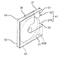
- the carrier tape 27 used by the component mounting device 14 to supply the component BH is fed out from the roll body 41 in the case in the present embodiment.
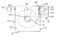
- the “cased roll body 41” refers to a roll body 27R in which the carrier tape 27 is rolled into a roll shape and is housed in the case 42 (see also FIG. 3).
- the roll body 41 in the case is different from the roll body with a reel that is conventionally used.
- the "roll body with a reel” means a roll body 27R held by a reel.
- the case 42 of the roll body 41 in the case will be described.
- the case 42 includes left and right side walls 51, a bottom wall 52, a front wall 53, and a rear wall 54, and has an upper opening 55 and a rear opening 56.
- a wireless tag 42M is attached to the outer surface of the front wall 53.
- Two upper and lower protrusion bases 51B projecting inward from the inner surface of one side wall 51 are provided on the upper portion of the rear wall 54, and the two protrusion bases 51B project outward in the horizontal direction.
- a tape tip holding portion 42K is provided (FIG. 4B).
- the side wall 51 on which the protrusion base 51B is provided is provided with a cutout portion 42D in which a portion sandwiched between the two protrusion bases 51B is cut off.
- the left and right side walls 51 of the case 42 are provided with groove portions 51M extending in a U shape from the edge portion on the upper opening 55 side toward the central portion side of each side wall 51.
- the feed hole 27K (the hole that engages with the outer peripheral teeth of the sprocket 26S) of the carrier tape 27 is inserted into the case 42.
- the provided tape tip holding portion 42K is inserted and locked.
- the cased roll body 41 is being stored or transported when the roll body 27R is stored in the case 42 and the carrier tape 27 is not pulled out from the roll body 27R for use.
- the two tape tip holding portions 42K provided in the case 42 are inserted into the two feed holes 27K and locked. As a result, the carrier tape 27 is prevented from coming off from the case 42 of the roll body 41 in the case during storage or transportation, and the entire roll body 27R is prevented from falling off from the case 42.
- the carrier tape 27 when the carrier tape 27 is pulled out from the cased roll body 41 and used, the two tape tip holding portions 42K are removed from the feed holes 27K of the carrier tape 27, and further, the front wall 53 as shown in FIG.
- the posture should be such that is the bottom surface.
- the carrier tape 27 By pulling out the carrier tape 27 from the rear opening 56 with the front wall 53 facing the lower surface in this way, the carrier tape 27 can be sent to the component supply unit 26.
- the tape tip holding portion 42K in the case 42 By providing the tape tip holding portion 42K in the case 42 in this way, the position of the tip portion of the carrier tape 27 in the case 42 is unified, so that the work of taking out the tip portion of the carrier tape 27 from the case 42 can be easily performed. be able to. Further, it is possible to easily handle the work of taking out the tip portion of the carrier tape 27 by an automated equipment such as a robot.
- Examples of the usage pattern of the cased roll body 41 for the component supply unit 26 include a form of being attached to the feeder carriage 25 as in the cased roll body 41 shown on the left side of FIG. 2, as well as the right side of FIG. 2 and FIG. 6A. Like the cased roll body 41 shown, there is a form of attaching to the component supply unit 26 via the attachment 26A. Alternatively, as shown in FIG. 6B, there is also a form in which the entire roll body 41 in a case is housed inside the component supply unit 26. Alternatively, as shown in FIG. 6C, there is also a form in which the roll body 27R is taken out from the cased roll body 41 and only the roll body 27R is stored inside the component supply unit 26.
- the case 42 of the cased roll body 41 serves as a support means for the roll body 27R when the roll body 27R is installed outside the component supply unit 26 and used (conventional). It can have the role of a reel in a roll body with a reel).
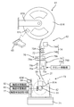
- the carrier tape processing device 3 is a device that processes the carrier tape 27 used in the component mounting device 14 to manufacture the roll body 41 in a case. As shown in FIG. 7, the carrier tape processing device 3 has a carrier tape supply unit 61 for supplying the carrier tape 27 containing the component BH, and a case 42 in which the carrier tape 27 is pulled out from the carrier tape supply unit 61 and rolled into a roll shape. A carrier tape processing unit 62, a handy scanner 63, and a writing unit 64 are provided.
- the carrier tape supply unit 61 includes a reel 61R around which a carrier tape 27 containing a component BH is wound, and a reel support unit 61S that rotatably supports the reel 61R.
- a code label 61L on which information (part information) of the component BH stored in the carrier tape 27 is recorded is attached to the reel 61R.
- An identifier (symbol) such as a barcode or a two-dimensional code is printed on the surface of the code label 61L.
- the carrier tape 27 is wound around the reel 61R in the opposite direction to the normal direction.
- a feed hole 27K appears on the left side, but a reel capable of directly supplying the carrier tape 27 to the parts supply unit 26 (hereinafter referred to as a reel). It appears on the right side in (called a normal reel). This is because the direction of the carrier tape 27 of the roll body 27R created by the roll body creating unit 73, which will be described later, is the same as that of the normal reel.
- the carrier tape processing unit 62 includes a case holding unit 71, a carrier tape feeding unit 72, a roll body creating unit 73, a measuring unit 74, a clamper 75, a cutter 76, and a shaft member extracting unit 77.
- the case holding portion 71 is composed of a conveyor mechanism extending in a horizontal case transport direction (direction perpendicular to the paper surface of FIG. 7).
- the case holding portion 71 holds each of the plurality of cases 42 in a line so that the upper opening 55 faces upward, and intermittently conveys the case 42 in the case conveying direction.
- the carrier tape feed unit 72 performs a feed operation of feeding the carrier tape 27 unwound from the reel 61R of the carrier tape supply unit 61 downward (that is, to the case 42 held by the case holding unit 71).
- the roll body creating unit 73 includes a shaft member 81, a shaft member moving unit 82, and a shaft member driving unit 83.
- the shaft member 81 is rotatably provided around a horizontal axis.
- a chuck portion 81A is provided on the shaft member 81, and the tip portion 27T of the carrier tape 27 can be sandwiched by the chuck portion 81A (FIGS. 8 ⁇ 9).
- the shaft member moving portion 82 has a shaft member 81 in which the tip portion 27T of the carrier tape 27 is sandwiched by the chuck portion 81A at a position above the case 42 (FIG. 9) and a position within the groove portion 51M of the case 42 (“inside the case”). It is referred to as "position” and has a function of moving to and from FIG. 10).
- the shaft member driving unit 83 rotates the shaft member 81 in a state where the shaft member 81 is moved to the position inside the case by the shaft member moving unit 82 (arrow R shown in FIG. 11). As a result, the carrier tape 27 is wound around the shaft member 81.
- the roll body creating portion 73 has a shaft member 81 that holds the tip portion 27T of the carrier tape 27, and by rotating the shaft member 81, the carrier tape 27 is wound around the shaft member 81 to form a roll-shaped roll body. It is configured to create 27R.
- the measuring unit 74 includes a length sensor 74A and a component counter 74B.
- the length sensor 74A measures the length of the carrier tape 27 pulled out from the carrier tape supply unit 61 by the carrier tape feed unit 72 based on the amount of movement of the carrier tape feed unit 72.
- the carrier tape feeding unit 72 includes a sprocket 72A for feeding out the carrier tape 27, and the length sensor 74A detects the amount of rotation of the sprocket 72A with an encoder or the like and measures the length of the pulled out carrier tape 27.
- the component counter 74B is located below the length sensor 74A and counts the number of component BHs pulled out from the carrier tape supply unit 61.
- the clamper 75 is provided below the component counter 74B.
- the clamper 75 includes a pair of clamp members 75b and 75c on the base portion 75a. By moving the pair of clamp members 75b and 75c so as to be close to each other, the carrier tape 27 located between the pair of clamp members 75b and 75c is clamped (FIGS. 11 ⁇ 12).
- the cutter 76 is provided between the component counter 74B and the clamper 75, and the two cutting members 76a and 76b are arranged so that the blade surfaces face each other.
- the carrier tape 27 extends downward between the two cutting members 76a and 76b and is clamped by the clamper 75 (FIG. 12). ⁇ Fig. 13).
- the base portion 75a of the clamper 75 (that is, the entire clamper 75) is at the end of the carrier tape 27 opposite to the tip 27T by the two clamp members 75b, 75c after the cutter 76 cuts the carrier tape 27.
- a certain cut end portion 27E (FIG. 14A) is moved by the clamper moving portion 75K (FIG. 7) while being clamped.
- the clamp member 75b enters the notch 42D provided in the case 42 (FIG. 14A ⁇ 14B)
- the cut end portion 27E of the carrier tape 27 is brought into the tape tip holding portion 42K provided in the case 42.
- Set (fix) (Fig. 14B; see also Fig. 5B).
- the base portion 75a of the clamper 75 is horizontally moved in the direction away from the case 42 to pull out the clamp member 75b from the notch portion 42D, and then the base portion 75a is pulled out. Is moved (retracted) above the case 42 (FIG. 14B ⁇ FIG. 15). As a result, the roll body 27R of the carrier tape 27 is formed in the case 42.
- the clamper 75 and the clamper moving portion 75K are provided with an end portion (cut end portion 27E) opposite to the tip portion 27T of the carrier tape 27 cut by the cutter 76 in the case 42.
- the carrier tape end setting portion 75S is set in the tape tip holding portion 42K.
- the shaft member extraction unit 77 extracts the shaft member 81 from the roll body 27R created by the roll body creation unit 73.
- the shaft member extraction unit 77 includes a mechanism for moving the shaft member 81 in the thickness direction of the created roll body 27R.
- the shaft member extraction portion 77 moves the shaft member 81 in the thickness direction of the roll body 27R, the roll body 27R is hindered by the side wall 51 of the case 42, so that the shaft member 81 is pulled out from the roll body 27R.
- the roll body 27R created by the roll body creating unit 73 is stored in the case 42.
- the handy scanner 63 is a device that optically reads an identifier such as a barcode.
- the handy scanner 63 is operated by an operator to read component information from the identifier of the code label 61L affixed to the reel 61R of the carrier tape supply unit 61.
- the "part information" is information about the part BH stored in the carrier tape 27 wound around the reel 61R of the carrier tape supply unit 61, and is the type, part name, characteristic, and date of manufacture of the part BH. It suffices to include at least one of the date, manufacturer, expiration date, number of parts, and access information (URL, etc.) for accessing this information.
- the handy scanner 63 is a part information acquisition unit that acquires part information which is information about the parts stored in the carrier tape 27.
- the component information acquisition unit uses a non-contact reader having a function of non-contactly reading the information recorded on the wireless tag instead of the handy scanner 63. May be used as.
- the writing unit 64 writes information to the wireless tag 42M of the case 42 held by the case holding unit 71 by wireless communication.
- the information written by the writing unit 64 to the wireless tag 42M is the component information acquired (read) through the handy scanner 63 and the identification information.
- the "identification information” is information used to identify the component BH stored in one roll body 27R used in the component mounting system 1 from the component BH housed in the other roll body 27R.
- the identification information is composed of, for example, a serial number issued in the factory where the component mounting system 1 is installed.
- the identification information is generated (issued) by the management computer 6 when the roll body 27R of the carrier tape 27 is generated, as will be described later.
- the identification information is also used as management information for managing the case 42. That is, the identification information is used for both the purpose of identifying the roll body 27R and the purpose of identifying the case 42.
- the storage warehouse 4 stores the roll body 41 in a case.
- the cased roll body 41 referred to here is not only the cased roll body 41 that has just been manufactured by the carrier tape processing device 3, but also the cased roll body 41 that has been used in the component mounting device 14 and has been returned in the middle of use.
- the roll body 41 is also included.
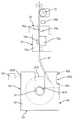
- the storage warehouse 4 has a plurality of shelves 92 (storage units) in the housing 91.
- An inlet 93 is provided below the front surface of the housing 91, and inside the housing 91, an operation of projecting the housing 91 to the outside (front side of the worker OP) through the inlet 93 and the housing 91.
- a moving table 94 is provided to perform a pulling operation to the inside (the back side seen from the worker OP).
- the moving table 94 is projected toward the front side of the worker OP, and the cased roll body 41 placed on the moving table 94 is placed in the housing 91. When it is housed in, it is pulled to the back side.
- Each of the plurality of shelves 92 provided in the storage warehouse 4 is predetermined with a plurality of storage positions 92S for storing (placeting) the roll body 41 in the case. That is, in the present embodiment, each shelf portion 92 is a storage unit provided with a plurality of storage positions 92S for storing the case 42 (that is, the roll body 41 in the case) containing the roll body 27R.
- a case transfer mechanism 95 is provided in the housing 91.
- the case transfer mechanism 95 is vertically extended by a Z-axis table 96 extending in the vertical direction (in the Z-axis direction) and a Z-axis table 96 extending in the front-rear direction (in the Y-axis direction) as seen from the operator OP.
- It includes a transfer head 99 that is moved in the axial direction.
- the Z-axis table 96 moves the Y-axis table 97 in the Z-axis direction
- the Y-axis table 97 moves the X-axis table 98 in the Y-axis direction
- the X-axis table 98 moves the transfer head.
- the transfer head 99 is moved three-dimensionally.
- the transfer head 99 includes two fingers 99F arranged in the X-axis direction.
- the phase head 99 can bring the two fingers 99F close to or separated from each other in the X-axis direction.
- the cased rolls 41 are gripped by the two fingers 99F (ie, by the transfer head 99). NS.
- the transfer head 99 is provided with a non-contact reader 100 whose imaging field of view is directed toward the back as viewed from the operator OP.
- the non-contact reader 100 faces the wireless tag 42M provided on the case 42 of the cased roll body 41 at the position where the transfer head 99 grips the cased roll body 41.
- the non-contact reader 100 reads the information written in the wireless tag 42M (part information and identification information of the component BH stored in the roll body 27R) by wireless communication in a state of facing the wireless tag 42M.
- the non-contact reader 100 functions as an identification information reading means for reading the identification information written in the wireless tag 42M as a storage unit.
- the non-contact reader 100 stores the read information in the management computer 6 (described later).
- a unique address is given to each storage position 92S defined for each of the plurality of shelves 92.
- the information (part information) of the part BH stored in the roll body 27R (carrier tape 27) of the cased roll body 41 is used.
- the identification information of the cased roll body 41 are stored in the management computer 6 (so-called associative information).
- information relating the component information and the information (storage position information) of the storage position 92S is stored in the management computer 6 (described later).
- the management computer 6 can grasp which storage position 92S of the storage warehouse 4 stores the cased roll body 41 in which the component BH is stored.
- FIG. 17 shows a block diagram of the control system in the entire component mounting system 1.
- the management computer 6 includes a production information management unit 101, a parts monitoring unit 102, a work instruction unit 103, and an information management unit 104.
- the production information management unit 101 stores the production plan data in the component mounting system 1.
- the component monitoring unit 102 monitors the remaining number of component BHs on the production line 2. When the component monitoring unit 102 is predicted to be out of parts, the component monitoring unit 102 notifies the work instruction unit 103 to that effect.
- the work instruction unit 103 issues work instructions for switching models based on the production planning data stored in the production information management unit 101 to the production line 2 and the worker OP, and is used in the production of the next model. Instructions such as withdrawal of parts BH to be performed are given to the storage warehouse 4. Further, the work instruction unit 103 issues a work instruction based on the information from the parts monitoring unit 102 (specifically, an instruction to pay out the replenishment parts to the storage warehouse 4 and an instruction to replenish the parts to the worker OP). ..
- the information management unit 104 includes a first information management unit 104a, a second information management unit 104b, an identification information generation unit 104c, and a storage position information generation unit 104d (FIG. 17).
- the first information management unit 104a manages the part information
- the second information management unit 104b manages the information (storage position information) of the storage position 92S of the part BH in the storage warehouse 4.
- the first information management unit 104a stores the generated roll body 27R in a state in which the component information and the identification information are associated with each other.
- the second information management unit 104b stores the generated identification information about the roll body 27R and the information (storage position information) of the storage position 92S in a state of being associated with each other.
- the identification information generation unit 104c generates (issues) identification information about the roll body 27R when the shaft member extraction unit 77 pulls out the shaft member 81 from the roll body 27R in the carrier tape processing device 3.
- the storage position information generation unit 104d specifies the storage position 92S of the cased roll body 41 and generates the storage position information.
- the carrier tape processing device 3 includes a processing device control unit 3C.
- the processing device control unit 3C includes a carrier tape processing unit 62 (case holding unit 71, carrier tape feeding unit 72, shaft member moving unit 82 of roll body creating unit 73, shaft member driving unit 83, and measuring unit) included in the carrier tape processing device 3. It controls 74 (length sensor 74A, component counter 74B), clamper 75, clamper moving unit 75K, cutter 76, shaft member extraction unit 77), handy scanner 63, and writing unit 64.
- the storage warehouse 4 includes a warehouse control unit 4C.
- the warehouse control unit 4C controls the moving table 94, the case transfer mechanism 95, and the non-contact reader 100 included in the storage warehouse 4.
- the processing device control unit 3C of the carrier tape processing device 3 acquires the part information of the carrier tape 27 wound around the reel 61R of the carrier tape supply unit 61 (part information acquisition step in step ST1).
- the component information is acquired by the operator OP reading the identifier of the code label 61L affixed to the reel 61R of the carrier tape supply unit 61 with the handy scanner 63 (FIG. 7), but another method. May be.
- the worker OP may input the contents of the code label 61L from an input device (not shown) connected to the processing device control unit 3C.
- the processing device control unit 3C After acquiring the component information of the carrier tape 27 wound around the reel 61R of the carrier tape supply unit 61 in step ST1, the processing device control unit 3C operates the case holding unit 71 to store the roll body 27R from now on.
- the case 42 empty case 42
- the processing device control unit 3C operates the shaft member moving unit 82 to be above the empty case 42 (that is, at the working position) held by the case holding unit 71.
- the shaft member 81 is moved to a predetermined position (step ST3, the shaft member upward movement step. FIG. 8).
- the processing device control unit 3C moves the shaft member 81 to a predetermined position above the case 42 in step ST3
- the carrier tape 27 is moved by the carrier tape feed unit 72 while rotating the reel 61R to feed the carrier tape 27 downward. Is fed downward to hold the tip portion 27T of the carrier tape 27 on the shaft member 81 (tape holding step in step ST4).
- the tip portion 27T of the carrier tape 27 is gripped by a robot or the like (not shown), and then the tip portion 27T of the carrier tape 27 is inserted between the shaft member 81 and the chuck portion 81A. Then, by operating the chuck portion 81A after that, the tip portion 27T of the carrier tape 27 is sandwiched between the shaft member 81 and the chuck portion 81A (FIGS. 9 ⁇ 10).
- Step ST5 the step of moving the shaft member downward. FIG. 10
- the processing device control unit 3C positions the shaft member 81 in the case
- the carrier tape feeding unit While the carrier tape 27 is pulled downward from the carrier tape supply unit 61 by 72 (carrier tape pulling step in step ST6), the carrier tape 27 is brought to the shaft member 81 by rotating the shaft member 81 by the shaft member driving unit 83.
- a roll-shaped roll body 27R is made by winding the roll body 27R (roll body making step in step ST7. FIG. 11).
- the processing device control unit 3C constitutes the measuring unit 74 after rotating the shaft member 81 and starting to wind the carrier tape 27 around the shaft member 81.
- the length sensor 74A measures the length of the carrier tape 27 pulled out (or the number of the pulled-out parts BH is measured by the part counter 74B constituting the measuring unit 74). Then, the processing device control unit 3C has reached a predetermined length of the carrier tape 27 drawn from the carrier tape supply unit 61 (or the component BH drawn from the carrier tape supply unit 61). When the number of the shaft members 81 reaches a predetermined number), the rotation of the shaft member 81 is stopped.
- the processing device control unit 3C clamps the carrier tape 27 with the clamper 75 (clamping step in step ST8. FIG. 11 ⁇ FIG. 12). Then, the cutter 76 is operated to cut the carrier tape 27 (cutting step of step ST9. FIG. 12 ⁇ FIG. 13).
- the processing device control unit 3C of the carrier tape processing device 3 cuts when the measuring unit 74 measures the length of the carrier tape 27 specified in advance or the number of parts BH specified in advance. It functions as a cutting control unit that causes the cutter 76 as a unit to cut the carrier tape 27.
- the processing device control unit 3C causes the cutter 76 to cut the carrier tape 27 when the length sensor 74A measures the length of the carrier tape 27 designated in advance.
- the cutter 76 may cut the carrier tape 27 when the 74B measures the number of pre-designated parts.
- the processing device control unit 3C When the processing device control unit 3C operates the cutter 76 to cut the carrier tape 27, the processing device control unit 3C operates the clamper moving unit 75K to cut the cut end portion 27E of the carrier tape 27 cut by the cutter 76 into the case 42 in the same manner as described above. It is fixed to the tape tip holding portion 42K provided in (step ST10, tape fixing step. FIG. 14A ⁇ FIG. 14B).
- the processing device control unit 3C moves the base portion 75a of the clamper 75 upward (FIG. 15) and operates the shaft member moving portion 82. Then, the shaft member 81 is pulled out from the case 42 (from the roll body 27R). As a result, the roll body 27R created by winding the carrier tape 27 around the shaft member 81 is stored in the case 42 (roll body storage step in step ST11). By this roll body storage process, one roll body 27R is stored in one empty case 42.
- step ST7 the carrier tape 27 pulled out in the carrier tape pulling-out step is rolled and stored in the case 42. It is a tape processing process.
- the processing device control unit 3C When the shaft member 81 is pulled out from the case 42 in step ST11, the processing device control unit 3C requests the identification information generation unit 104c of the management computer 6 to generate identification information about the roll body 27R in the case 42. Then, the identification information generation unit 104c requested to generate the identification information by the processing device control unit 3C generates the identification information about the roll body 27R in the case 42 (identification information generation step in step ST12).
- the processing device control unit 3C receives the generated identification information. Then, the writing unit 64 writes the component information acquired in step ST1 and the identification information generated in step ST12 to the wireless tag 42M attached to the case 42 (case 42 in which the roll body 27R is housed). (Writing step of step ST13).
- the processing device control unit 3C writes the part information and the identification information to the wireless tag 42M of the case 42, and then transmits the information written to the wireless tag 42M (part information and identification information about the roll body 27R) to the management computer 6.
- the information (part information and identification information) is stored in the first information management unit 104a of the management computer 6.
- the management computer is associated with the identification information which is the unique information of the roll body 27R and the part information which is the information of the part BH stored in the roll body 27R. It is registered in 6 (part information registration step in step ST14).
- the processing device control unit 3C When the processing device control unit 3C writes the information about the roll body 27R to the first information management unit 104a of the management computer 6, it determines whether or not all the cased roll bodies 41 to be manufactured have been manufactured (step ST15). End judgment process). Then, when it is determined that all the cased rolls 41 have not been manufactured yet, it is determined that the process returns to step ST2 to newly manufacture the cased rolls 41 and all the cased rolls 41 have been manufactured. In this case, the production of the roll body 41 in the case (processing work of the carrier tape 27) by the carrier tape processing device 3 is completed.
- the warehouse control unit 4C of the storage warehouse 4 moves the moving table 94 toward the front side from the entrance 93 provided in the housing 91.
- the worker OP or a mobile robot (not shown) places the cased roll body 41 on the moving table 94 (placement step of step ST21; FIG. 19).
- the roll body 41 in the case is placed on the moving table 94 in a posture in which the upper opening 55 faces upward and the front wall 53 faces the front side (the side of the worker OP).
- the wireless tag 42M provided on the case 42 is in a state of facing the front side (FIG. 16).
- the warehouse control unit 4C When the cased roll body 41 is placed on the moving table 94, the warehouse control unit 4C operates the moving table 94 to pull the cased roll body 41 into the housing 91. When the cased roll body 41 is pulled into the housing 91, the warehouse control unit 4C moves the transfer head 99 to the front side of the cased roll body 41 placed on the moving table 94. Then, the two fingers 99F are operated so as to close, and the transfer head 99 is made to grip the roll body 41 in the case. At this time, the non-contact reader 100 provided in the transfer head 99 faces the wireless tag 42M provided in the case 42 of the roll body 41 in the case, and the non-contact reader 100 reads the identification information written in the wireless tag 42M. (Step of reading identification information in step ST22).
- the warehouse control unit 4C transmits the identification information read by the non-contact reader 100 to the management computer 6. Then, the management computer 6 that receives the identification information from the warehouse control unit 4C receives the identification information from the storage position information generation unit 104d in the cased roll body 41 (the case where the non-contact reader 100 reads the identification information) corresponding to the identification information.
- the storage position 92S in the storage warehouse 4 of the roll body 41) is specified and the storage position information is generated (the storage position information generation step in step ST23).
- the storage position 92S is specified by arbitrarily selecting from the storage positions 92S that are vacant at that time or according to a predetermined rule.
- the management computer 6 associates the generated storage position information with the identification information of the cased roll 41 corresponding to the storage position information. In this state, it is stored in the second information management unit 104b.
- the identification information that is unique information of the roll body 27R and the storage of the cased roll body 41 including the roll body 27R in the storage warehouse 4 It is registered in the management computer 6 in a state associated with the position information (storage position information) (storage position information registration step in step ST24).
- the management computer 6 stores the storage information and the identification information of the cased roll body 41 placed on the moving table 94 in the second information management unit 104b in a state of being associated with each other. Then, the management computer 6 operates the case transfer mechanism 95 to transfer and store the cased roll body 41 placed on the moving table 94 to the storage position 92S corresponding to the storage position information (step ST25). Storage process). As a result, the storage work of the roll body 41 in the case is completed.
- the roll body 27R in which the carrier tape 27 pulled out from the reel 61R of the carrier tape supply unit 61 is rolled is stored in the case 42, so that the roll body 27R is stored in the case 42. It can be treated as.
- the roll body 41 in the case can be made more compact by making the dimension in the width direction smaller than that of the roll body with a reel, and the reel does not remain as waste after the roll body 27R (that is, the carrier tape 27) is used up. So workability is also good.
- the case 42 is not only inexpensive in itself, but can be reused (reused) unlike the reel, so that the cost can be reduced in that respect as well.
- the case 42 is provided with a wireless tag 42M as a storage unit capable of storing component information, and the component information of the carrier tape 27 wound around the reel 61R is transmitted to the wireless tag 42M. Can be written and memorized. Further, since the component information and the identification information which is the unique information of the roll body 27R can be associated and stored, the component information can be managed in each unit of the cased roll body 41.
- the carrier tape processing device 3 has a processing device control unit 3C, a carrier tape processing unit 62, a handy scanner 63 as a component information reading unit, a writing unit 64, and a storage warehouse 4 (warehouse control unit 4C, shelf).
- the generation unit 104d) constitutes the parts management device 110 (FIG. 17).
- part information is acquired (part information acquisition process), identification information is generated (identification information generation process), and then these part information
- the identification information is written in the wireless tag 42M provided in the case 42 (writing step), and the written component information and the identification information are associated with each other and stored in the first information management unit 104a (part information registration step).
- the identification information written in the wireless tag 42M is read by the identification information reading unit (non-contact reader 100) (identification information reading step), the storage position 92S is specified, and the storage position information is generated (storage position information generation).
- the identification information and the storage position information are associated with each other and stored in the second information management unit 104b (storage position information registration step).
- the parts information and the identification information of the cased roll body 41 are stored in association with each other, and the identification information of the cased roll body 41 and the storage position information are stored in association with each other.
- the cased roll 41 can be smoothly stored and taken out in the storage warehouse 4. Therefore, according to the parts management device 110 (parts management method) in the present embodiment, the warehousing and warehousing of the parts BH can be easily and efficiently performed.
- FIG. 20 illustrates an image of the operation of the cased roll body 41 in the component mounting system 1 according to the present embodiment.
- the cased roll body 41 according to the present embodiment is manufactured by supplying the reel 61R around which the carrier tape 27 is wound and the case 42 to the carrier tape processing device 3.
- a part of the cased roll body 41 manufactured by the carrier tape processing device 3 is sent to the production line 2 for use, and the other part is stored (stored) in the storage warehouse 4.
- the cased roll body 41 stored in the storage warehouse 4 is delivered from there and sent to the production line 2 for use.
- case 42 generated by the carrier tape 27 of the cased roll body 41 being used up in the production line 2 is collected and supplied to the carrier tape processing device 3 and reused for manufacturing a new cased roll body 41.
- a part of the cased roll body 41 sent to the production line 2 in a state where the carrier tape 27 has not been used up is returned to the storage warehouse 4 and stored (stocked).
- the roll body 27R obtained by rolling the carrier tape 27 drawn from the reel 61R of the carrier tape supply unit 61 into a roll shape is used as the case 42.
- the roll body 27R can be handled as a roll body 41 in a case.
- the roll body 41 in the case can be made more compact by making the dimension in the width direction smaller than that of the roll body with a reel, and the reel does not remain as waste after the roll body 27R (that is, the carrier tape 27) is used up. So workability is also good.
- the case 42 is not only inexpensive in itself, but can be reused (reused) unlike a reel, so that the cost can be reduced in that respect as well. Therefore, according to the carrier tape processing device 3 (carrier tape processing method) in the present embodiment, it is possible to realize a reelless component supply form with an inexpensive configuration.
- the present disclosure is not limited to the above-mentioned ones, and various modifications and the like are possible.
- the specific configuration of the carrier tape processing unit 62 shown in the above-described embodiment is merely an example, and if the carrier tape 27 can be pulled out from the carrier tape supply unit 61, rolled, and stored in the case 42. Its composition is free.
- the reel 61R a reel in which the carrier tape 27 is wound from a commonly distributed ordinary reel may be used. In this case, the handy scanner 63 reads the part information from the identifier of the normal reel, not from the reel 61R.
- Carrier tape processing device 3C Processing device control unit (cutting control unit) 27 Carrier tape 27T Tip 27E Cut end (opposite end) 27R Roll body 41 Roll body with case 42 Case 61 Carrier tape supply part 62 Carrier tape processing part 64 Writing part 73 Roll body making part 74 Measuring part 75S Carrier tape end setting part 76 Cutter (cutting part) 77 Shaft member extraction unit 81 Shaft member 104 Information management unit 104a First information management unit 104b Second information management unit 104c Identification information generation unit BH parts
Abstract
部品を収納したキャリアテープを供給するキャリアテープ供給部と、キャリアテープをキャリアテープ供給部から引き出してロール状にしてケースに収納するキャリアテープ処理部を備える。更に、キャリアテープ処理部は、キャリアテープの先端部を保持する軸部材を有し、軸部材を回転させることによりキャリアテープを軸部材に巻き付けてロール状のロール体を作成するロール体作成部と、ロール体作成部が作成したロール体から軸部材を抜き取る軸部材抜き取り部を備える。
Description
本開示は、部品を収納したキャリアテープを処理するキャリアテープ処理装置およびキャリアテープ処理方法に関する。
従来、基板に部品を搭載する部品実装装置における部品供給ユニットとして、部品を収納したキャリアテープを搬送することにより部品取出し位置に部品を供給するテープフィーダが知られている。テープフィーダにおいて使用されるキャリアテープはその保持体としてのリールに巻き付けられており、キャリアテープの運搬や保管および部品供給ユニットに対するセット等は、リールに巻き付けられた状態のまま(リール付きロール体のまま)行われる。
このようなテープフィーダにおいて、リールは規格品であってその幅方向寸法を縮小化することは難しいことや、キャリアテープの使用が終了した後には空のリールが発生し、その処理や保管に手間がかかること等から、リールをなくし、キャリアテープをロール状に巻いたロール体の状態で部品供給ユニットに供給できるようにする装置が提案されている(例えば、下記の特許文献1)。特許文献1では、キャリアテープのロール体を部品の補充用の手段(部品補給手段)から部品供給ユニットの収納部に投入するようになっており、部品供給ユニットがキャリアテープを引き出し終わった後に不要なリールが実装作業現場に残らないようになっている。
そこで本開示は、安価な構成でリールなしの部品供給形態を実現できるキャリアテープ処理装置およびキャリアテープ処理方法を提供することを目的とする。
本開示のキャリアテープ処理装置は、部品を収納したキャリアテープを供給するキャリアテープ供給部と、キャリアテープをキャリアテープ供給部から引き出してロール状にしてケースに収納するキャリアテープ処理部とを備える。
本開示のキャリアテープ処理方法は、部品を収納したキャリアテープを供給するキャリアテープ供給部からキャリアテープを引き出すキャリアテープ引き出し工程と、キャリアテープ引き出し工程で引き出した前記キャリアテープをロール状にしてケースに収納するキャリアテープ処理工程とを含む。
本開示によれば、安価な構成でリールなしの部品供給形態を実現できる。
本開示の実施の形態の説明に先立ち、従来の装置における問題点を簡単に説明する。
特許文献1に記載の装置では、部品供給ユニットにキャリアテープのロール体を供給するための大掛かりな装置(部品補給手段)が必要であってコストがかかるという問題点がある。
以下、図面を参照して本開示の実施の形態について説明する。図1は本開示の一実施の形態におけるキャリアテープ処理装置を含む部品実装システム1の構成図を示している。部品実装システム1は、製造ライン2と、製造ライン2に供給される部品の供給に関連するキャリアテープ処理装置3と、部品の保管と管理に関連する保管倉庫4を備えている。製造ライン2は、直列に連結された複数の装置の間でKBを受け渡ししながら作業を施すことによって基板KBに部品が装着された実装基板JKを製造する。
図1において、製造ライン2は情報管理端末5を通じて管理コンピュータ6に繋がっている。管理コンピュータ6は、製造ライン2を構成する各装置の動作の管理を行う。また、図1に示すように、キャリアテープ処理装置3と保管倉庫4も管理コンピュータ6と繋がっている。管理コンピュータ6は、キャリアテープ処理装置3と保管倉庫4の動作の管理も行う。図1に示すように、管理コンピュータ6には作業者用端末7が接続されており、部品実装システム1の作業者は作業者用端末7から部品実装システム1に対して種々の操作入力を行うことができるようになっている。
先ず、製造ライン2について説明する。図1において、製造ライン2は、基板供給装置11、印刷装置12、印刷後検査装置13、複数の部品実装装置14、実装後検査装置15、リフロー装置16、最終検査装置17および基板回収装置18を備えている。
基板供給装置11は基板KBを下流側の印刷装置12に順次供給する。印刷装置12は基板供給装置11から供給される基板KBを搬入し、基板KBの表面に形成された電極にペースト状の半田を塗布して下流側の印刷後検査装置13に搬出する。印刷後検査装置13は印刷装置12から搬出された基板KBを搬入し、半田の塗布状態が不良な箇所がないかどうかをカメラで観察して検査したうえで、下流側の部品実装装置14に基板KBを搬出する。
各部品実装装置14は、上流側から搬入された基板KBに部品を装着して下流側に搬出する。最も下流側に位置する部品実装装置14はその下流側に位置する実装後検査装置15に基板KBを搬出する。部品実装装置14については後述する。
実装後検査装置15は、最も下流側に位置する部品実装装置14から搬出された基板KBを搬入し、部品の装着状態が不良な箇所がないかどうかをカメラで観察して検査したうえで、下流側のリフロー装置16に基板KBを搬出する。リフロー装置16は実装後検査装置15から搬出された基板KBを搬入し、リフロー炉を通過させることによって半田を溶融・固化させて部品を電極に接合させる。最終検査装置17はリフロー装置16を通過した基板KBを搬入し、部品の電極への接合状態をカメラで観察して検査したうえで、下流側の基板回収装置18に搬出する。基板回収装置18は最終検査装置17から搬出された基板KBを受け取って回収する。
次に、図2を用いて部品実装装置14について説明する。図2において、部品実装装置14の基台21上には基台カバー22が設けられており、基台21と基台カバー22との間の作業空間23には基板KBを水平方向に搬送する基板搬送路24が設けられている。
基台21上の基板搬送路24を挟んだ両側の位置にはフィーダ台車25が連結されている。各フィーダ台車25には複数の部品供給ユニット26が取り付けられている。ここでは部品供給ユニット26はテープフィーダであり、スプロケット26Sによってキャリアテープ27を搬送することにより、所定の部品供給位置に部品BHをひとつずつ供給する。
図2において、作業空間23内には、ヘッド移動機構31によって水平面内方向に移動される装着ヘッド32が設けられている。装着ヘッド32には部品吸着ノズル33が下方に延びて設けられている。部品吸着ノズル33の下端には、部品供給ユニット26が供給する部品BHが吸着される。
各部品実装装置14は、基板搬送路24が上流側から基板KBを搬入して位置決めしたら、部品供給ユニット26により部品BHを供給させながら装着ヘッド32に装着ターンを繰り返し行わせる。装着ヘッド32はひとつの装着ターンにおいて、部品供給ユニット26が供給する部品BHを吸着してピックアップする動作と、基板KB上の定められた部品搭載位置に部品BHを装着する動作を、この順で行う。装着ヘッド32に装着ターンを繰り返し行わせて基板KBに装着させるべき部品BHを全て装着したら、基板搬送路24を作動させて、基板KBを下流側に搬出する。
ここで、部品実装装置14が部品BHの供給に使用するキャリアテープ27は、本実施の形態では、ケース入りロール体41から繰り出されるようになっている。ここで「ケース入りロール体41」とは、キャリアテープ27をロール状にしたロール体27Rがケース42に収納されたものをいう(図3も参照)。ケース入りロール体41は、従来用いられているリール付きのロール体とは異なるものである。ここで「リール付きのロール体」とは、ロール体27Rがリールにより保持されたものをいう。
ここで、ケース入りロール体41のケース42について説明する。ケース42は、図4Aに示すように、左右の側壁51、底壁52、前壁53および後壁54を備えており、上方開口55と後開口56を有している。前壁53の外面には無線タグ42Mが貼り付けられている。後壁54の上部には、一方の側壁51の内面から内方へ張り出した上下の2つの突起ベース51Bが設けられており、2つの突起ベース51Bには、水平方向の外側に向かって突出したテープ先端保持部42Kが設けられている(図4B)。また、突起ベース51Bを設けた方の側壁51は、2つの突起ベース51Bに挟まれた部分が切り取られた切り欠き部42Dを備えている。ケース42の左右の側壁51には、上方開口55側の縁部からそれぞれの側壁51の中央部側に向かってU字形状に延びた溝部51Mが設けられている。
図5A、図5Bに示すように、ケース入りロール体41を保管中或いは運搬中であるときには、キャリアテープ27が有する送り孔27K(スプロケット26Sの外周歯と係合する孔)に、ケース42に設けられたテープ先端保持部42Kを差し込んで係止しておくようにする。なお、ケース入りロール体41を保管中或いは運搬中であるときとは、ケース42にロール体27Rを収納した場合であって、ロール体27Rからキャリアテープ27を引き出して使用する状況にないときを言う。本実施の形態では2つの送り孔27Kに、ケース42に設けられた2つのテープ先端保持部42Kを差し込んで係止する。これにより保管中或いは運搬中にケース入りロール体41のケース42からキャリアテープ27が抜け出ることが防止され、ひいてはロール体27Rの全体がケース42から脱落することが防止される。
一方、ケース入りロール体41からキャリアテープ27を引き出して使用する状況にあるときには、2つのテープ先端保持部42Kをキャリアテープ27の送り孔27Kから取り外し、更には図3に示すように前壁53が下面となるような姿勢にする。このように前壁53が下面となるような姿勢にしてキャリアテープ27を後開口56から引き出すことにより、キャリアテープ27を部品供給ユニット26に送ることが可能となる。このように、ケース42にテープ先端保持部42Kを設けることにより、ケース42におけるキャリアテープ27の先端部の位置が統一されるので、ケース42からキャリアテープ27の先端部を取り出す作業を容易に行うことができる。また、キャリアテープ27の先端部を取り出す作業をロボット等の自動化設備で行わせることにも容易に対応できる。
部品供給ユニット26に対するケース入りロール体41の使用形態としては、例えば、図2の左側に示すケース入りロール体41のように、フィーダ台車25に取り付ける形態のほか、図2の右側および図6Aに示すケース入りロール体41のように、アタッチメント26Aを介して部品供給ユニット26に取り付ける形態がある。或いは、図6Bに示すように、ケース入りロール体41の全体を部品供給ユニット26の内部に収納する形態もある。また或いは、図6Cに示すように、ケース入りロール体41からロール体27Rを取り出し、ロール体27Rのみを部品供給ユニット26の内部に収納する形態もある。
このように、本実施の形態において、ケース入りロール体41のケース42には、ロール体27Rを部品供給ユニット26の外部に設置して使用するときにおけるロール体27Rの支持手段の役割(従来のリール付きのロール体におけるリールの役割)を持たせることができる。
次に、キャリアテープ処理装置3について説明する。キャリアテープ処理装置3は、部品実装装置14で使用されるキャリアテープ27を処理してケース入りロール体41を製造する装置である。キャリアテープ処理装置3は、図7に示すように、部品BHを収納したキャリアテープ27を供給するキャリアテープ供給部61と、キャリアテープ27をキャリアテープ供給部61から引き出してロール状にしてケース42に収納するキャリアテープ処理部62と、ハンディスキャナ63および書き込み部64とを備えている。
図7において、キャリアテープ供給部61は、部品BHを収納したキャリアテープ27が巻き付けられたリール61Rと、リール61Rを回転自在に支持したリール支持部61Sを備えている。リール61Rには、キャリアテープ27に収納された部品BHの情報(部品情報)が記録されたコードラベル61Lが貼り付けられている。コードラベル61Lは表面にバーコードや二次元コード等の識別子(シンボル)が印刷されている。リール61Rには、通常とは逆向きでキャリアテープ27を巻き取っている。8mm幅の紙テープのキャリアテープの場合、リール61Rから手前にキャリアテープ27を引き出すと左側に送り孔27Kが現れるが、部品供給ユニット26にキャリアテープ27を直接供給することが可能なリール(以下、通常のリールと呼ぶ)では右側に現れる。これは、後述するロール体作成部73で作成されたロール体27Rのキャリアテープ27の向きを通常のリールと同じ向きにするためである。
図7において、キャリアテープ処理部62は、ケース保持部71、キャリアテープ送り部72、ロール体作成部73、計測部74、クランパ75、カッタ76および軸部材抜き取り部77を備えている。
ケース保持部71は、水平なケース搬送方向(図7の紙面に垂直な方向)に延びたコンベア機構から構成されている。ケース保持部71は複数のケース42それぞれを上方開口55が上を向くように一列に並べて状態に保持し、かつ、ケース搬送方向に向けて間欠的に搬送する。
キャリアテープ送り部72は、キャリアテープ供給部61のリール61Rから繰り出されるキャリアテープ27を下方に(すなわちケース保持部71に保持されたケース42に)向けて送る送り動作をする。
図7において、ロール体作成部73は、軸部材81、軸部材移動部82、軸部材駆動部83を備えている。軸部材81は水平軸まわりに回転自在に設けられている。軸部材81にはチャック部81Aが設けられており、チャック部81Aにより、キャリアテープ27の先端部27Tを挟み込むことができるようになっている(図8→図9)。
軸部材移動部82は、キャリアテープ27の先端部27Tをチャック部81Aにより挟み込んだ軸部材81を、ケース42の上方の位置(図9)と、ケース42の溝部51M内の位置(「ケース内位置」と称する。図10)との間で移動させる機能を有する。軸部材駆動部83は、軸部材移動部82によって、軸部材81がケース内位置に移動された状態において、軸部材81を回転させる(図11中に示す矢印R)。これにより軸部材81のまわりにはキャリアテープ27が巻き付けられていく。
このようにロール体作成部73は、キャリアテープ27の先端部27Tを保持する軸部材81を有し、軸部材81を回転させることによりキャリアテープ27を軸部材81に巻き付けてロール状のロール体27Rを作成する構成となっている。
図7において、計測部74は、長さセンサ74Aと部品カウンタ74Bから構成されている。長さセンサ74Aは、キャリアテープ送り部72の動作量に基づいて、キャリアテープ送り部72がキャリアテープ供給部61から引き出したキャリアテープ27の長さを計測する。キャリアテープ送り部72はキャリアテープ27を繰り出すスプロケット72Aを備えており、長さセンサ74Aはスプロケット72Aの回転量をエンコーダ等で検出して引き出されたキャリアテープ27の長さを計測する。部品カウンタ74Bは、長さセンサ74Aの下方に位置しており、キャリアテープ供給部61から引き出された部品BHの数をカウントする。
図7において、クランパ75は部品カウンタ74Bの下方に設けられている。クランパ75は、ベース部75a上に一対のクランプ部材75b,75cを備えている。一対のクランプ部材75b,75cは互いに近接するように移動することによって、一対のクランプ部材75b,75cの間に位置するキャリアテープ27をクランプする(図11→図12)。
図7において、カッタ76は部品カウンタ74Bとクランパ75の間に設けられており、2つの切断部材76a,76bが刃面を対向させて配置されている。2つの切断部材76a,76bは互いに近接する方向に移動されることで、2つの切断部材76a,76bの間を下方に延び、かつ、クランパ75によってクランプされたキャリアテープ27を切断する(図12→図13)。
クランパ75のベース部75aは(すなわちクランパ75の全体は)、カッタ76がキャリアテープ27を切断した後、2つのクランプ部材75b,75cによってキャリアテープ27の先端部27Tとは反対側の端部である切断端部27E(図14A)をクランプした状態のまま、クランパ移動部75K(図7)によって移動される。そして、クランプ部材75bがケース42に設けられた切り欠き部42Dへ進入することによって(図14A→図14B)、キャリアテープ27の切断端部27Eをケース42に設けられたテープ先端保持部42Kにセット(固定)する(図14B。図5Bも参照)。そして、クランパ75によるキャリアテープ27のクランプを解除したうえで、クランパ75のベース部75aをケース42から離れる方向へ水平に移動させて切り欠き部42Dからクランプ部材75bを引き抜き、その後、ベース部75aをケース42の上方に移動(退避)させる(図14B→図15)。これによりケース42内にはキャリアテープ27のロール体27Rが形成された状態となる。
このように本実施の形態において、クランパ75およびクランパ移動部75Kは、カッタ76で切断されたキャリアテープ27の先端部27Tとは反対側の端部(切断端部27E)をケース42に設けたテープ先端保持部42Kにセットするキャリアテープ端セット部75Sとなっている。
軸部材抜き取り部77は、ロール体作成部73が作成したロール体27Rから軸部材81を抜き取る。軸部材抜き取り部77は、軸部材81を、作成したロール体27Rの厚み方向へ移動させる機構を備える。軸部材抜き取り部77が軸部材81をロール体27Rの厚み方向へ移動させると、ロール体27Rはケース42の側壁51によって移動が妨げられるので、軸部材81はロール体27Rから引き抜かれる。これによりロール体作成部73によって作成されたロール体27Rは、ケース42に収納された状態となる。
ハンディスキャナ63は、バーコード等の識別子を光学的に読み取る装置である。ハンディスキャナ63は作業者によって操作され、キャリアテープ供給部61のリール61Rに貼り付けられているコードラベル61Lの識別子から部品情報を読み取る。ここで「部品情報」とは、キャリアテープ供給部61のリール61Rに巻き付けられているキャリアテープ27に収納されている部品BHに関する情報であり、部品BHの種類、部品名、特性、製造年月日、製造者、使用期限、部品数及びこれらの情報にアクセスするためのアクセス情報(URL等)の少なくともひとつを含んでいればよい。
このように本実施の形態において、ハンディスキャナ63は、キャリアテープ27に収納された部品に関する情報である部品情報を取得する部品情報取得部となっている。なお、リール61Rが部品情報を記憶した無線タグを有している場合、ハンディスキャナ63に替えて、無線タグに記録されている情報を非接触で読み取る機能を有する非接触リーダを部品情報取得部として使用してもよい。
書き込み部64は、ケース保持部71によって保持されているケース42の無線タグ42Mに情報を無線通信によって書き込む。書き込み部64が無線タグ42Mに書き込む情報は、ハンディスキャナ63を通じて取得した(読み取った)部品情報と、識別情報である。
ここで「識別情報」とは、部品実装システム1において使用される一のロール体27Rに収納されている部品BHを他のロール体27Rに収納されている部品BHと識別するために使用する情報である。識別情報は、例えば、部品実装システム1が設置される工場内において発行されるシリアル番号によって構成される。本実施の形態では、識別情報は、後述するように、キャリアテープ27のロール体27Rが生成された際に、管理コンピュータ6において生成(発行)される。また、識別情報はケース42を管理するための管理情報としても利用される。すなわち、識別情報は、ロール体27Rを識別する目的とケース42を識別する目的の両方で使用される。
次に、保管倉庫4について説明する。保管倉庫4は、ケース入りロール体41を保管する。ここでいうケース入りロール体41とは、キャリアテープ処理装置3によって製造されたばかりのケース入りロール体41だけでなく、部品実装装置14において使用されて途中で戻されたような使用途中のケース入りロール体41も含まれる。
図16において、保管倉庫4は、筐体91内に複数の棚部92(保管部)を有している。筐体91の前面下方には、入口93が設けられており、筐体91の内部には、入口93を通じて筐体91の外部(作業者OPの手前側)への張り出し動作と筐体91の内部(作業者OPから見た奥側)への引き込み動作とを行う移動テーブル94が設けられている。移動テーブル94は、ケース入りロール体41が保管倉庫4に保管される際には作業者OPの手前側へ張り出され、移動テーブル94に載置されたケース入りロール体41を筐体91内に収容するときには奥側に引き込まれる。
保管倉庫4が備える複数の棚部92のそれぞれには、ケース入りロール体41を保管(載置)するための複数の保管位置92Sが予め定められている。すなわち本実施の形態において、各棚部92は、ロール体27Rを収納したケース42(すなわちケース入りロール体41)を保管する保管位置92Sを複数備えた保管部となっている。
図16において、筐体91内にはケース移送機構95が設けられている。ケース移送機構95は、上下方向(Z軸方向とする)に延びたZ軸テーブル96と、作業者OPから見た前後方向(Y軸方向とする)に延びてZ軸テーブル96によって上下方向に移動されるY軸テーブル97と、作業者OPから見た横方向(X軸方向とする)に延びてY軸テーブル97によって前後方向に移動されるX軸テーブル98と、X軸テーブル98によってX軸方向に移動される移送ヘッド99とを備えている。
ケース移送機構95は、Z軸テーブル96によるY軸テーブル97のZ軸方向への移動動作と、Y軸テーブル97によるX軸テーブル98のY軸方向への移動と、X軸テーブル98による移送ヘッド99のX軸方向への移動とによって、移送ヘッド99を三次元的に移動させる。移送ヘッド99はX軸方向に並んだ2つのフィンガ99Fを備えている。
位相ヘッド99は、2つのフィンガ99FをX軸方向に互いに近接或いは離間させることができる。2つのフィンガ99Fの間にケース入りロール体41が位置した状態で2つのフィンガ99Fが閉じるように作動されると、ケース入りロール体41は2つのフィンガ99Fによって(すなわち移送ヘッド99によって)把持される。
図16において、移送ヘッド99には、撮像視野を作業者OPから見た奥方向に向けた非接触リーダ100が設けられている。非接触リーダ100は、移送ヘッド99がケース入りロール体41を把持する位置において、ケース入りロール体41のケース42に設けられた無線タグ42Mと正対するようになっている。
非接触リーダ100は、無線タグ42Mと正対した状態において、無線タグ42Mに書き込まれている情報(ロール体27Rに収納されている部品BHの部品情報と識別情報)を無線通信にて読み取る。本実施の形態において、非接触リーダ100は、記憶部としての無線タグ42Mに書き込まれた識別情報を読み取る識別情報読み取り手段として機能するようになっている。非接触リーダ100は、ケース入りロール体41の無線タグ42Mに書き込まれている情報を読み取ったら、その読み取った情報を管理コンピュータ6に記憶させる(後述)。
複数の棚部92のそれぞれに定められた各保管位置92Sにはユニークな住所が与えられている。本実施の形態では、保管位置92Sにケース入りロール体41を保管(載置)するときには、ケース入りロール体41のロール体27R(キャリアテープ27)に収納されている部品BHの情報(部品情報)と、ケース入りロール体41の識別情報とを関連付けた(いわゆる紐付けした)情報が管理コンピュータ6に記憶される。さらに、部品情報と、保管位置92Sの情報(保管位置情報)とを関連付けた情報が管理コンピュータ6に記憶される(後述)。これにより管理コンピュータ6は、保管倉庫4のどの保管位置92Sに、どの部品BHを収納したケース入りロール体41が保管されているかを把握することができる。
図17は部品実装システム1の全体における制御系統をブロック図により示したものである。図17に示すように、管理コンピュータ6は、生産情報管理部101、部品監視部102、作業指示部103および情報管理部104を備えている。生産情報管理部101は部品実装システム1における生産計画データを記憶している。部品監視部102は、製造ライン2における部品BHの残数等を監視する。部品監視部102は部品切れが予測される場合、その旨を作業指示部103に伝達する。
作業指示部103は、生産情報管理部101に記憶されている生産計画データに基づく機種の切り替え時の作業指示を、製造ライン2と作業者OPに対して行うとともに、次の機種の生産で使用する部品BHの払い出し等の指示を、保管倉庫4に対して行う。また作業指示部103は、部品監視部102からの情報に基づく作業指示(具体的には、保管倉庫4に対する補充用部品の払い出しの指示と、作業者OPに対する部品補充作業の指示)等を行う。
情報管理部104は、第1の情報管理部104a、第2の情報管理部104b、識別情報生成部104cおよび保管位置情報生成部104dを備えている(図17)。第1の情報管理部104aは部品情報を管理し、第2の情報管理部104bは保管倉庫4内における部品BHの保管位置92Sの情報(保管位置情報)を管理する。具体的には、第1の情報管理部104aは、生成されたロール体27Rについての部品情報と識別情報とを関連付けた状態で記憶する。また、第2の情報管理部104bは、生成されたロール体27Rについての識別情報と保管位置92Sの情報(保管位置情報)とを関連付けた状態で記憶する。
識別情報生成部104cは、キャリアテープ処理装置3において、軸部材抜き取り部77がロール体27Rから軸部材81を抜き取ったとき等に、ロール体27Rについての識別情報を生成(発行)する。保管位置情報生成部104dは、ケース入りロール体41が保管倉庫4に保管される際に、ケース入りロール体41の保管位置92Sを特定して保管位置情報を生成する。
図17に示すように、キャリアテープ処理装置3は処理装置制御部3Cを備えている。処理装置制御部3Cはキャリアテープ処理装置3が備えるキャリアテープ処理部62(ケース保持部71、キャリアテープ送り部72、ロール体作成部73の軸部材移動部82と軸部材駆動部83、計測部74(長さセンサ74A、部品カウンタ74B)、クランパ75、クランパ移動部75K、カッタ76、軸部材抜き取り部77)、ハンディスキャナ63および書き込み部64の制御を行う。また図17に示すように、保管倉庫4は倉庫制御部4Cを備えている。倉庫制御部4Cは、保管倉庫4が備える移動テーブル94、ケース移送機構95および非接触リーダ100の制御を行う。
次に、図18に示すフローチャートに従って、キャリアテープ処理装置3によるケース入りロール体41の製造作業(キャリアテープ27の処理作業)の流れを説明する。先ず、キャリアテープ処理装置3の処理装置制御部3Cは、キャリアテープ供給部61のリール61Rに巻き付けられているキャリアテープ27の部品情報を取得する(ステップST1における部品情報取得工程)。ここでは、部品情報の取得は、作業者OPがハンディスキャナ63によって、キャリアテープ供給部61のリール61Rに貼り付けられたコードラベル61Lの識別子を読み取ることによって行うが(図7)、他の方法によってもよい。例えば、作業者OPが、処理装置制御部3Cに繋がる入力装置(図示せず)から、コードラベル61Lの内容に相当する入力を行うのであってもよい。
ステップST1でキャリアテープ供給部61のリール61Rに巻き付けられているキャリアテープ27の部品情報を取得したら、処理装置制御部3Cは、ケース保持部71を作動させて、これからロール体27Rを収納させようとするケース42(空のケース42)を、リール61Rの下方の作業位置に位置決めする(ステップST2のケース位置決め工程)。そして、ケース42を作業位置に位置決めしたら、処理装置制御部3Cは、軸部材移動部82を作動させて、ケース保持部71によって保持されている空のケース42の(すなわち作業位置の)上方の所定位置に軸部材81を移動させる(ステップST3の軸部材上方移動工程。図8)。
処理装置制御部3Cは、ステップST3で軸部材81をケース42の上方の所定位置に移動させたら、リール61Rを回転させてキャリアテープ27を下方に繰り出させながらキャリアテープ送り部72によってキャリアテープ27を下方に送り、キャリアテープ27の先端部27Tを軸部材81に保持させる(ステップST4のテープ保持工程)。このテープ保持工程は、図示しないロボット等によって、キャリアテープ27の先端部27Tを把持させたうえで、キャリアテープ27の先端部27Tを軸部材81とチャック部81Aの間に挿通させるようにする。そして、その後にチャック部81Aを作動させることで、軸部材81とチャック部81Aとの間にキャリアテープ27の先端部27Tが挟み込まれるようにする(図9→図10)。
処理装置制御部3Cは、キャリアテープ27の先端部27Tを軸部材81に保持させたら、軸部材移動部82を作動させて、軸部材81をケース保持部71によって作業位置に位置決めされたケース42のケース内位置に位置するように移動させる(ステップST5の軸部材下方移動工程。図10)そして、処理装置制御部3Cは、軸部材81をケース内に位置に位置させたら、キャリアテープ送り部72によってキャリアテープ供給部61からキャリアテープ27を下方に引き出す一方で(ステップST6のキャリアテープ引き出し工程)、軸部材駆動部83により軸部材81を回転させることによって、キャリアテープ27を軸部材81に巻き付けてロール状のロール体27Rを作成する(ステップST7のロール体作成工程。図11)。
処理装置制御部3Cは、ステップST6のキャリアテープ引き出し工程とステップST7のロール体作成工程では、軸部材81を回転させて軸部材81にキャリアテープ27を巻き付け始めた後、計測部74を構成する長さセンサ74Aによって、キャリアテープ27が引き出された長さを計測する(或いは計測部74を構成する部品カウンタ74Bによって、引き出された部品BHの数を計測する)。そして、処理装置制御部3Cは、キャリアテープ供給部61から引き出されたキャリアテープ27の長さが予め定められた所定の長さに達した(或いは、キャリアテープ供給部61から引き出された部品BHの数が予め定められた所定の数に達した)場合に、軸部材81の回転を停止させるようにする。
処理装置制御部3Cは、ロール体27Rが作成されたら、クランパ75によってキャリアテープ27をクランプする(ステップST8のクランプ工程。図11→図12)。そして、カッタ76を作動させて、キャリアテープ27を切断する(ステップST9の切断工程。図12→図13)。
このように本実施の形態において、キャリアテープ処理装置3の処理装置制御部3Cは、計測部74が予め指定されたキャリアテープ27の長さもしくは予め指定された部品BHの数を計測したら、切断部としてのカッタ76にキャリアテープ27の切断を実行させる切断制御部として機能するようになっている。なお、ここでは、処理装置制御部3Cは、長さセンサ74Aが予め指定されたキャリアテープ27の長さを計測したときにカッタ76にキャリアテープ27を切断させるようになっているが、部品カウンタ74Bが予め指定された部品の数を計測したときにカッタ76にキャリアテープ27を切断させるようになっていてもよい。
処理装置制御部3Cは、カッタ76を作動させてキャリアテープ27を切断したら、クランパ移動部75Kを作動させ、前述の要領によって、カッタ76によって切断されたキャリアテープ27の切断端部27Eをケース42に設けられたテープ先端保持部42Kに固定する(ステップST10のテープ固定工程。図14A→図14B)。
処理装置制御部3Cは、ステップST10でキャリアテープ27の切断端部27Eをケース42に固定したら、クランパ75のベース部75aを上方移動させたうえで(図15)、軸部材移動部82を作動させて、ケース42から(ロール体27Rから)軸部材81を引き抜く。これにより軸部材81にキャリアテープ27が巻き付けられることによって作成されたロール体27Rが、ケース42に収納される(ステップST11のロール体収納工程)。このロール体収納工程により、ひとつの空のケース42に1個のロール体27Rが収納されることになる。
ここで、上記のロール体作成工程(ステップST7)からロール体収納工程(ステップST11)までの一連の工程は、キャリアテープ引き出し工程で引き出したキャリアテープ27をロール状にしてケース42に収納するキャリアテープ処理工程となっている。
処理装置制御部3Cは、ステップST11で軸部材81をケース42から抜き取るとき、管理コンピュータ6の識別情報生成部104cに、ケース42内のロール体27Rについての識別情報の生成を要請する。そして、処理装置制御部3Cから識別情報の生成を要請された識別情報生成部104cは、ケース42内のロール体27Rについての識別情報を生成する(ステップST12の識別情報生成工程)。
ステップST12で識別情報生成部104cによって識別情報が生成されたら、処理装置制御部3Cは、その生成された識別情報を受け取る。そして、書き込み部64によって、ステップST1で取得した部品情報と、ステップST12で生成された識別情報を、ケース42(ロール体27Rが収納されているケース42)に取り付けられている無線タグ42Mに書き込む(ステップST13の書き込み工程)。
処理装置制御部3Cは、部品情報と識別情報をケース42の無線タグ42Mに書き込んだら、無線タグ42Mに書き込んだ情報(ロール体27Rについての部品情報および識別情報)を管理コンピュータ6に送信し、管理コンピュータ6の第1の情報管理部104aに、その情報(部品情報および識別情報)を記憶させる。これにより、ケース42内のロール体27Rについて、ロール体27Rの固有の情報である識別情報と、ロール体27Rに収納されている部品BHの情報である部品情報とが関連付けられた状態で管理コンピュータ6に登録される(ステップST14の部品情報登録工程)。
処理装置制御部3Cは、ロール体27Rについての情報を管理コンピュータ6の第1の情報管理部104aに書き込んだら、製造しようとしているケース入りロール体41を全て製造したかどうかを判断する(ステップST15の終了判断工程)。そして、まだ全てのケース入りロール体41を製造していないと判断した場合にはステップST2に戻って新たにケース入りロール体41を製造し、全てのケース入りロール体41を製造したと判断した場合には、キャリアテープ処理装置3によるケース入りロール体41の製造(キャリアテープ27の処理作業)を終了する。
次に、図19に示すフローチャートを用いて、ケース入りロール体41の保管作業の流れを説明する。これには先ず、保管倉庫4の倉庫制御部4Cが、筐体91に設けられた入口93から移動テーブル94を手前側に移動させる。そして、作業者OPが(あるいは図示しない移動ロボットが)、移動テーブル94にケース入りロール体41を載置する(ステップST21の載置工程。図19)。このときケース入りロール体41は、上方開口55が上を向き、かつ、前壁53が手前側(作業者OPの側)を向く姿勢で移動テーブル94に載置される。これによりケース42に設けられた無線タグ42Mは、手前側を向いた状態となる(図16)。
移動テーブル94にケース入りロール体41が載置されたら、倉庫制御部4Cは移動テーブル94を作動させて、ケース入りロール体41を筐体91内に引き込む。ケース入りロール体41が筐体91内に引き込まれたら、倉庫制御部4Cは移動テーブル94に載置されているケース入りロール体41の手前側に移送ヘッド99を移動させる。そして、2つのフィンガ99Fを閉じるように作動させて、移送ヘッド99にケース入りロール体41を把持させる。このとき移送ヘッド99に設けられた非接触リーダ100はケース入りロール体41のケース42に設けられた無線タグ42Mと正対し、非接触リーダ100は無線タグ42Mに書き込まれている識別情報を読み取る(ステップST22の識別情報読み取り工程)。
非接触リーダ100が無線タグ42Mに書き込まれている識別情報を読み取ったら、倉庫制御部4Cは、非接触リーダ100が読み取った識別情報を管理コンピュータ6に送信する。そして、倉庫制御部4Cから識別情報の送信を受けた管理コンピュータ6は、保管位置情報生成部104dにおいて、その識別情報に対応するケース入りロール体41(非接触リーダ100が識別情報を読み取ったケース入りロール体41)の保管倉庫4内における保管位置92Sを特定して保管位置情報を生成する(ステップST23の保管位置情報生成工程)。保管位置92Sの特定は、その時点で空き状態となっている保管位置92Sの中から任意に或いは所定の規則に従って選択してなされる。
ステップST23で保管位置情報生成部104dが保管位置情報を生成したら、管理コンピュータ6は、その生成された保管位置情報と、その保管位置情報に対応するケース入りロール体41の識別情報とを関連付けた状態で、第2の情報管理部104bに記憶させる。これにより、保管倉庫4に保管されようとしているケース入りロール体41について、ロール体27Rの固有の情報である識別情報と、ロール体27Rを含むケース入りロール体41の保管倉庫4内での保管位置の情報(保管位置情報)とが関連付けられた状態で管理コンピュータ6に登録される(ステップST24の保管位置情報登録工程)。
管理コンピュータ6は、移動テーブル94に載置されたケース入りロール体41についての保管情報と識別情報とを関連付けた状態で第2の情報管理部104bに記憶させる。そして、管理コンピュータ6は、ケース移送機構95を作動させて、移動テーブル94に載置されたケース入りロール体41を、保管位置情報に対応する保管位置92Sに移送して保管する(ステップST25の保管工程)。これによりケース入りロール体41の保管作業が終了する。
このように、本実施の形態では、キャリアテープ供給部61のリール61Rから引き出したキャリアテープ27をロール状にしたロール体27Rをケース42に収納することで、ロール体27Rをケース入りロール体41として取り扱うことができるようになっている。ケース入りロール体41はリール付きのロール体よりも幅方向寸法を小さくしてコンパクト化を図ることができるうえ、ロール体27Rを(すなわちキャリアテープ27を)使い切った後にリールが廃棄物として残らないので作業性もよい。また、ケース42はそれ自体が安価であるだけでなく、リールと異なって再使用(使い回し)ができるので、その面でもコストを安価にすることができる。
更に、本実施の形態では、ケース42に部品情報を記憶させることができる記憶部としての無線タグ42Mが設けられており、リール61Rに巻き付けられているキャリアテープ27の部品情報を無線タグ42Mに書き込んで記憶させることができる。また、部品情報とロール体27Rの固有の情報である識別情報とを関連付けられて記憶されせることができるので、ケース入りロール体41ひとつひとつの単位で部品情報を管理することが可能である。
上述の部品実装システム1において、キャリアテープ処理装置3の処理装置制御部3C、キャリアテープ処理部62、部品情報読み取り部としてのハンディスキャナ63、書き込み部64、保管倉庫4(倉庫制御部4C、棚部92、ケース移送機構95、識別情報読み取り部としての非接触リーダ100)、情報管理部104(第1の情報管理部104a、第2の情報管理部104b、識別情報生成部104cおよび保管位置情報生成部104d)は部品管理装置110を構成している(図17)。
部品管理装置110を用いた部品BHの管理作業(部品管理方法)は、先ず、部品情報を取得し(部品情報取得工程)、識別情報を生成したうえで(識別情報生成工程)、これら部品情報と識別情報をケース42に設けられた無線タグ42Mに書き込み(書き込み工程)、その書き込んだ部品情報と識別情報とを関連付けて第1の情報管理部104aに記憶させる(部品情報登録工程)。そして、無線タグ42Mに書き込んだ識別情報を識別情報読み取り部(非接触リーダ100)によって読み取り(識別情報読み取り工程)、保管位置92Sを特定して保管位置情報を生成したうえで(保管位置情報生成工程)、識別情報と保管位置情報とを関連付けて第2の情報管理部104bに記憶させる(保管位置情報登録工程)という手順で実行される。
このような部品管理方法によれば、ケース入りロール体41についての部品情報と識別情報が関連付けて記憶されるほか、ケース入りロール体41の識別情報と保管位置情報とが関連付けて記憶されるので、保管倉庫4におけるケース入りロール体41の保管および取り出しをスムーズに行うことができる。このため本実施の形態における部品管理装置110(部品管理方法)によれば、部品BHの入庫および出庫を簡単かつ効率よく行うことができる。
図20は、本実施の形態における部品実装システム1におけるケース入りロール体41の運用のイメージを図示したものである。この図に示すように、本実施の形態におけるケース入りロール体41は、キャリアテープ27が巻き付けられたリール61Rとケース42がキャリアテープ処理装置3に供給されることで製造される。キャリアテープ処理装置3で製造されたケース入りロール体41の一部は製造ライン2に送られて使用され、他の一部は保管倉庫4に保管(入庫)される。保管倉庫4に保管されたケース入りロール体41は、そこから出庫されて製造ライン2に送られ、使用される。そして、製造ライン2でケース入りロール体41のキャリアテープ27が使い切られることによって生じたケース42は回収されてキャリアテープ処理装置3に供給され、新たなケース入りロール体41の製造に再利用される。また、製造ライン2に送られたケース入りロール体41であって、キャリアテープ27がまだ使い切られていない状態のものの一部は、保管倉庫4に戻されて保管(入庫)される。
以上説明したように、本実施の形態のおけるキャリアテープ処理装置3(キャリアテープ処理方法)では、キャリアテープ供給部61のリール61Rから引き出したキャリアテープ27をロール状にしたロール体27Rをケース42に収納することで、ロール体27Rをケース入りロール体41として取り扱うことができるようになっている。ケース入りロール体41はリール付きのロール体よりも幅方向寸法を小さくしてコンパクト化を図ることができるうえ、ロール体27Rを(すなわちキャリアテープ27を)使い切った後にリールが廃棄物として残らないので作業性もよい。
また、ケース42はそれ自体が安価であるだけでなく、リールと異なって再使用(使い回し)ができるので、その面でもコストを安価にすることができる。このため本実施の形態におけるキャリアテープ処理装置3(キャリアテープ処理方法)によれば、安価な構成でリールなしの部品供給形態を実現できる。
これまで本開示の実施の形態について説明してきたが、本開示は上述したものに限定されず、種々の変形等が可能である。例えば、上述の実施の形態において示したキャリアテープ処理部62の具体的構成は例示に過ぎず、キャリアテープ27をキャリアテープ供給部61から引き出してロール状にしてケース42に収納することができれば、その構成は自由である。また、リール61Rには、一般的に流通している通常のリールからキャリアテープ27を巻き取ったものを使用してもよい。この場合、ハンディスキャナ63はリール61Rからではなく、通常のリールの識別子から部品情報を読み取るようにする。
安価な構成でリールなしの部品供給形態を実現できるキャリアテープ処理装置およびキャリアテープ処理方法を提供する。
3 キャリアテープ処理装置
3C 処理装置制御部(切断制御部)
27 キャリアテープ
27T 先端部
27E 切断端部(反対側の端部)
27R ロール体
41 ケース入りロール体
42 ケース
61 キャリアテープ供給部
62 キャリアテープ処理部
64 書き込み部
73 ロール体作成部
74 計測部
75S キャリアテープ端セット部
76 カッタ(切断部)
77 軸部材抜き取り部
81 軸部材
104 情報管理部
104a 第1の情報管理部
104b 第2の情報管理部
104c 識別情報生成部
BH 部品
3C 処理装置制御部(切断制御部)
27 キャリアテープ
27T 先端部
27E 切断端部(反対側の端部)
27R ロール体
41 ケース入りロール体
42 ケース
61 キャリアテープ供給部
62 キャリアテープ処理部
64 書き込み部
73 ロール体作成部
74 計測部
75S キャリアテープ端セット部
76 カッタ(切断部)
77 軸部材抜き取り部
81 軸部材
104 情報管理部
104a 第1の情報管理部
104b 第2の情報管理部
104c 識別情報生成部
BH 部品
Claims (12)
- 部品を収納したキャリアテープを供給するキャリアテープ供給部と、
前記キャリアテープを前記キャリアテープ供給部から引き出してロール状にしてケースに収納するキャリアテープ処理部と、を備えたキャリアテープ処理装置。 - 前記キャリアテープ処理部は、
前記キャリアテープの先端部を保持した軸部材を有し、前記軸部材を回転させることにより前記キャリアテープを前記軸部材に巻き付けてロール状のロール体を作成するロール体作成部と、
前記ロール体作成部が作成した前記ロール体から前記軸部材を抜き取る軸部材抜き取り部と、を備えた請求項1に記載のキャリアテープ処理装置。 - 前記キャリアテープ処理部は、前記キャリアテープ供給部から引き出されたキャリアテープを切断する切断部を備えた請求項2に記載のキャリアテープ処理装置。
- 前記キャリアテープ処理部は、
前記キャリアテープ供給部から引き出されたキャリアテープの長さもしくは前記キャリアテープ供給部から引き出された前記部品の数を計測する計測部と、
前記計測部が予め指定されたキャリアテープの長さもしくは予め指定された部品の数を計測したら前記切断部にキャリアテープの切断を実行させる切断制御部と、を有する請求項3に記載のキャリアテープ処理装置。 - 前記キャリアテープ処理部は、前記切断部で切断されたキャリアテープの前記先端部とは反対側の端部を前記ケースに設けたテープ先端保持部にセットするキャリアテープ端セット部を有する請求項4に記載のキャリアテープ処理装置。
- 空の前記ケースを保持するケース保持部を有し、前記ケース保持部が保持するひとつの前記空の前記ケースに1個の前記ロール体が収納される請求項2に記載のキャリアテープ処理装置。
- 部品を収納したキャリアテープを供給するキャリアテープ供給部からキャリアテープを引き出すキャリアテープ引き出し工程と、
前記キャリアテープ引き出し工程で引き出した前記キャリアテープをロール状にしてケースに収納するキャリアテープ処理工程と、を含むキャリアテープ処理方法。 - 前記キャリアテープ処理工程は、
前記キャリアテープの先端部を保持した軸部材を回転させることにより前記キャリアテープを前記軸部材に巻き付けてロール状のロール体を作成するロール体作成工程と、
前記ロール体から前記軸部材を抜き取って前記ロール体を前記ケースに収納するロール体収納工程と、を含む請求項7に記載のキャリアテープ処理方法。 - 前記キャリアテープ処理工程は、前記キャリアテープ引き出し工程で引き出したキャリアテープを切断する切断工程を含む請求項8に記載のキャリアテープ処理方法。
- 前記キャリアテープ処理工程は、
前記キャリアテープ引き出し工程で引き出したキャリアテープの長さもしくは前記キャリアテープ引出工程で引き出した前記部品の数を計測する計測工程と、
前記計測工程で予め指定されたキャリアテープの長さもしくは予め指定された部品の数を計測したら前記切断工程を実行する請求項9に記載のキャリアテープ処理方法。 - 前記キャリアテープ処理工程は、前記切断工程で切断したキャリアテープの前記先端部とは反対側の端部を前記ケースに設けたテープ先端保持部にセットするキャリアテープ端セット工程を含む請求項10に記載のキャリアテープ処理方法。
- 前記ロール体収納工程は、ひとつの空の前記ケースに1個の前記ロール体を収納する請求項8に記載のキャリアテープ処理方法。
Priority Applications (4)
| Application Number | Priority Date | Filing Date | Title |
|---|---|---|---|
| US17/905,638 US20230114831A1 (en) | 2020-03-25 | 2021-01-21 | Carrier-tape processing device and carrier-tape processing method |
| CN202180017847.9A CN115211249A (zh) | 2020-03-25 | 2021-01-21 | 载带处理装置及载带处理方法 |
| DE112021001830.2T DE112021001830T5 (de) | 2020-03-25 | 2021-01-21 | Carrier-Tape-Verarbeitungsvorrichtung und Carrier-Tape-Verarbeitungsverfahren |
| JP2021535617A JP7178566B2 (ja) | 2020-03-25 | 2021-01-21 | キャリアテープ処理装置およびキャリアテープ処理方法 |
Applications Claiming Priority (2)
| Application Number | Priority Date | Filing Date | Title |
|---|---|---|---|
| JP2020-053535 | 2020-03-25 | ||
| JP2020053535 | 2020-03-25 |
Publications (1)
| Publication Number | Publication Date |
|---|---|
| WO2021192558A1 true WO2021192558A1 (ja) | 2021-09-30 |
Family
ID=77890109
Family Applications (1)
| Application Number | Title | Priority Date | Filing Date |
|---|---|---|---|
| PCT/JP2021/001958 WO2021192558A1 (ja) | 2020-03-25 | 2021-01-21 | キャリアテープ処理装置およびキャリアテープ処理方法 |
Country Status (5)
| Country | Link |
|---|---|
| US (1) | US20230114831A1 (ja) |
| JP (2) | JP7178566B2 (ja) |
| CN (1) | CN115211249A (ja) |
| DE (1) | DE112021001830T5 (ja) |
| WO (1) | WO2021192558A1 (ja) |
Citations (5)
| Publication number | Priority date | Publication date | Assignee | Title |
|---|---|---|---|---|
| JPH04173584A (ja) * | 1990-10-24 | 1992-06-22 | Murata Mfg Co Ltd | チップ状電子部品のためのパッケージ |
| JPH0521990A (ja) * | 1991-07-17 | 1993-01-29 | Matsushita Electric Ind Co Ltd | 電子部品集合体および電子部品集合体の供給装置 |
| JP2005119880A (ja) * | 2004-10-14 | 2005-05-12 | Shin Etsu Polymer Co Ltd | テープ巻取装置 |
| JP2006114764A (ja) * | 2004-10-15 | 2006-04-27 | Murata Mfg Co Ltd | パッケージ電子部品および電子部品マウンタ |
| WO2020202737A1 (ja) * | 2019-03-29 | 2020-10-08 | パナソニックIpマネジメント株式会社 | キャリアテープ保持装置、保持体およびキャリアテープパッケージ体 |
Family Cites Families (5)
| Publication number | Priority date | Publication date | Assignee | Title |
|---|---|---|---|---|
| JPS5845268Y2 (ja) * | 1976-11-30 | 1983-10-14 | 太陽誘電株式会社 | 電子部品の包装箱 |
| JPS6228377A (ja) * | 1985-07-24 | 1987-02-06 | 株式会社村田製作所 | 電子部品連収納体 |
| WO2006038385A1 (ja) | 2004-09-30 | 2006-04-13 | Shibaura Mechatronics Corporation | 接着膜テープ収納用カセット交換装置、接着膜テープ収納用カセット及び接着膜貼付装置 |
| JP2006290610A (ja) | 2005-04-15 | 2006-10-26 | Brother Ind Ltd | ラベル用テープロール及びラベル用カートリッジ |
| CN108128667A (zh) | 2016-12-01 | 2018-06-08 | 何政豪 | 具无线射频识别的智能型卷盘 |
-
2021
- 2021-01-21 JP JP2021535617A patent/JP7178566B2/ja active Active
- 2021-01-21 DE DE112021001830.2T patent/DE112021001830T5/de active Pending
- 2021-01-21 WO PCT/JP2021/001958 patent/WO2021192558A1/ja active Application Filing
- 2021-01-21 US US17/905,638 patent/US20230114831A1/en active Pending
- 2021-01-21 CN CN202180017847.9A patent/CN115211249A/zh active Pending
-
2022
- 2022-07-13 JP JP2022112212A patent/JP7349607B2/ja active Active
Patent Citations (5)
| Publication number | Priority date | Publication date | Assignee | Title |
|---|---|---|---|---|
| JPH04173584A (ja) * | 1990-10-24 | 1992-06-22 | Murata Mfg Co Ltd | チップ状電子部品のためのパッケージ |
| JPH0521990A (ja) * | 1991-07-17 | 1993-01-29 | Matsushita Electric Ind Co Ltd | 電子部品集合体および電子部品集合体の供給装置 |
| JP2005119880A (ja) * | 2004-10-14 | 2005-05-12 | Shin Etsu Polymer Co Ltd | テープ巻取装置 |
| JP2006114764A (ja) * | 2004-10-15 | 2006-04-27 | Murata Mfg Co Ltd | パッケージ電子部品および電子部品マウンタ |
| WO2020202737A1 (ja) * | 2019-03-29 | 2020-10-08 | パナソニックIpマネジメント株式会社 | キャリアテープ保持装置、保持体およびキャリアテープパッケージ体 |
Also Published As
| Publication number | Publication date |
|---|---|
| CN115211249A (zh) | 2022-10-18 |
| DE112021001830T5 (de) | 2023-01-05 |
| US20230114831A1 (en) | 2023-04-13 |
| JP7349607B2 (ja) | 2023-09-25 |
| JP7178566B2 (ja) | 2022-11-28 |
| JP2022140485A (ja) | 2022-09-26 |
| JPWO2021192558A1 (ja) | 2021-09-30 |
Similar Documents
| Publication | Publication Date | Title |
|---|---|---|
| JP6377752B2 (ja) | 部品実装システム及び部品実装方法 | |
| US11470751B2 (en) | Component-mounting system and management device | |
| JP2007019320A (ja) | 電子回路基板の生産管理方法及び生産管理システム | |
| WO2021192557A1 (ja) | キャリアテープ処理装置およびキャリアテープ処理方法 | |
| JP6676482B2 (ja) | 電子部品供給システム | |
| JP2017130593A (ja) | フィーダ自動交換システム | |
| JP2019176188A (ja) | 部品実装システム | |
| JP6684015B2 (ja) | 部品実装システム及び部品実装方法 | |
| JP6694767B2 (ja) | スプライシングユニット及び電子部品供給システム | |
| WO2021192558A1 (ja) | キャリアテープ処理装置およびキャリアテープ処理方法 | |
| WO2021192408A1 (ja) | 部品管理装置および部品管理方法 | |
| JP6120862B2 (ja) | リール管理システム及びリール管理方法 | |
| WO2021181759A1 (ja) | 保持装置および部品装着システム | |
| JP2021153153A (ja) | キャリアテープ処理装置およびキャリアテープ処理方法 | |
| JP6704451B2 (ja) | スプライシングユニット | |
| US20230114399A1 (en) | Component mounting system and method for handling carrier tape roll body | |
| JP2006332090A (ja) | 電子部品実装装置および電子部品実装装置における部品情報管理方法 | |
| JP2021153154A (ja) | 部品実装システムおよびキャリアテープロール体の処理方法 | |
| JP2021153152A (ja) | キャリアテープロール体 | |
| JP7403045B2 (ja) | キャリアテープロール体製造装置およびキャリアテープロール体の製造方法 | |
| WO2023139789A1 (ja) | 準備装置、実装装置、実装システム及び情報処理方法 | |
| JP6990147B2 (ja) | 部品実装システム | |
| JP2021182626A (ja) | 部品実装システムおよび部品実装方法 | |
| CN116605564A (zh) | 供给架、生产系统、以及供给方法 |
Legal Events
| Date | Code | Title | Description |
|---|---|---|---|
| ENP | Entry into the national phase |
Ref document number: 2021535617 Country of ref document: JP Kind code of ref document: A |
|
| 121 | Ep: the epo has been informed by wipo that ep was designated in this application |
Ref document number: 21774201 Country of ref document: EP Kind code of ref document: A1 |
|
| 122 | Ep: pct application non-entry in european phase |
Ref document number: 21774201 Country of ref document: EP Kind code of ref document: A1 |