WO2021187366A1 - 蓄電デバイス電極に適したバインダー、バインダー溶液、蓄電デバイス電極スラリー、蓄電デバイス電極および蓄電デバイス - Google Patents
蓄電デバイス電極に適したバインダー、バインダー溶液、蓄電デバイス電極スラリー、蓄電デバイス電極および蓄電デバイス Download PDFInfo
- Publication number
- WO2021187366A1 WO2021187366A1 PCT/JP2021/010081 JP2021010081W WO2021187366A1 WO 2021187366 A1 WO2021187366 A1 WO 2021187366A1 JP 2021010081 W JP2021010081 W JP 2021010081W WO 2021187366 A1 WO2021187366 A1 WO 2021187366A1
- Authority
- WO
- WIPO (PCT)
- Prior art keywords
- storage device
- binder
- water
- mass
- soluble resin
- Prior art date
- Legal status (The legal status is an assumption and is not a legal conclusion. Google has not performed a legal analysis and makes no representation as to the accuracy of the status listed.)
- Ceased
Links
Classifications
-
- C—CHEMISTRY; METALLURGY
- C08—ORGANIC MACROMOLECULAR COMPOUNDS; THEIR PREPARATION OR CHEMICAL WORKING-UP; COMPOSITIONS BASED THEREON
- C08K—Use of inorganic or non-macromolecular organic substances as compounding ingredients
- C08K5/00—Use of organic ingredients
- C08K5/16—Nitrogen-containing compounds
- C08K5/34—Heterocyclic compounds having nitrogen in the ring
- C08K5/3412—Heterocyclic compounds having nitrogen in the ring having one nitrogen atom in the ring
- C08K5/3415—Five-membered rings
-
- C—CHEMISTRY; METALLURGY
- C08—ORGANIC MACROMOLECULAR COMPOUNDS; THEIR PREPARATION OR CHEMICAL WORKING-UP; COMPOSITIONS BASED THEREON
- C08L—COMPOSITIONS OF MACROMOLECULAR COMPOUNDS
- C08L29/00—Compositions of homopolymers or copolymers of compounds having one or more unsaturated aliphatic radicals, each having only one carbon-to-carbon double bond, and at least one being terminated by an alcohol, ether, aldehydo, ketonic, acetal or ketal radical; Compositions of hydrolysed polymers of esters of unsaturated alcohols with saturated carboxylic acids; Compositions of derivatives of such polymers
- C08L29/02—Homopolymers or copolymers of unsaturated alcohols
- C08L29/04—Polyvinyl alcohol; Partially hydrolysed homopolymers or copolymers of esters of unsaturated alcohols with saturated carboxylic acids
-
- H—ELECTRICITY
- H01—ELECTRIC ELEMENTS
- H01G—CAPACITORS; CAPACITORS, RECTIFIERS, DETECTORS, SWITCHING DEVICES, LIGHT-SENSITIVE OR TEMPERATURE-SENSITIVE DEVICES OF THE ELECTROLYTIC TYPE
- H01G11/00—Hybrid capacitors, i.e. capacitors having different positive and negative electrodes; Electric double-layer [EDL] capacitors; Processes for the manufacture thereof or of parts thereof
- H01G11/22—Electrodes
- H01G11/30—Electrodes characterised by their material
- H01G11/32—Carbon-based
- H01G11/38—Carbon pastes or blends; Binders or additives therein
-
- H—ELECTRICITY
- H01—ELECTRIC ELEMENTS
- H01M—PROCESSES OR MEANS, e.g. BATTERIES, FOR THE DIRECT CONVERSION OF CHEMICAL ENERGY INTO ELECTRICAL ENERGY
- H01M4/00—Electrodes
- H01M4/02—Electrodes composed of, or comprising, active material
- H01M4/13—Electrodes for accumulators with non-aqueous electrolyte, e.g. for lithium-accumulators; Processes of manufacture thereof
-
- H—ELECTRICITY
- H01—ELECTRIC ELEMENTS
- H01M—PROCESSES OR MEANS, e.g. BATTERIES, FOR THE DIRECT CONVERSION OF CHEMICAL ENERGY INTO ELECTRICAL ENERGY
- H01M4/00—Electrodes
- H01M4/02—Electrodes composed of, or comprising, active material
- H01M4/13—Electrodes for accumulators with non-aqueous electrolyte, e.g. for lithium-accumulators; Processes of manufacture thereof
- H01M4/139—Processes of manufacture
- H01M4/1391—Processes of manufacture of electrodes based on mixed oxides or hydroxides, or on mixtures of oxides or hydroxides, e.g. LiCoOx
-
- H—ELECTRICITY
- H01—ELECTRIC ELEMENTS
- H01M—PROCESSES OR MEANS, e.g. BATTERIES, FOR THE DIRECT CONVERSION OF CHEMICAL ENERGY INTO ELECTRICAL ENERGY
- H01M4/00—Electrodes
- H01M4/02—Electrodes composed of, or comprising, active material
- H01M4/24—Electrodes for alkaline accumulators
-
- H—ELECTRICITY
- H01—ELECTRIC ELEMENTS
- H01M—PROCESSES OR MEANS, e.g. BATTERIES, FOR THE DIRECT CONVERSION OF CHEMICAL ENERGY INTO ELECTRICAL ENERGY
- H01M4/00—Electrodes
- H01M4/02—Electrodes composed of, or comprising, active material
- H01M4/24—Electrodes for alkaline accumulators
- H01M4/26—Processes of manufacture
-
- H—ELECTRICITY
- H01—ELECTRIC ELEMENTS
- H01M—PROCESSES OR MEANS, e.g. BATTERIES, FOR THE DIRECT CONVERSION OF CHEMICAL ENERGY INTO ELECTRICAL ENERGY
- H01M4/00—Electrodes
- H01M4/02—Electrodes composed of, or comprising, active material
- H01M4/24—Electrodes for alkaline accumulators
- H01M4/32—Nickel oxide or hydroxide electrodes
-
- H—ELECTRICITY
- H01—ELECTRIC ELEMENTS
- H01M—PROCESSES OR MEANS, e.g. BATTERIES, FOR THE DIRECT CONVERSION OF CHEMICAL ENERGY INTO ELECTRICAL ENERGY
- H01M4/00—Electrodes
- H01M4/02—Electrodes composed of, or comprising, active material
- H01M4/62—Selection of inactive substances as ingredients for active masses, e.g. binders, fillers
-
- Y—GENERAL TAGGING OF NEW TECHNOLOGICAL DEVELOPMENTS; GENERAL TAGGING OF CROSS-SECTIONAL TECHNOLOGIES SPANNING OVER SEVERAL SECTIONS OF THE IPC; TECHNICAL SUBJECTS COVERED BY FORMER USPC CROSS-REFERENCE ART COLLECTIONS [XRACs] AND DIGESTS
- Y02—TECHNOLOGIES OR APPLICATIONS FOR MITIGATION OR ADAPTATION AGAINST CLIMATE CHANGE
- Y02E—REDUCTION OF GREENHOUSE GAS [GHG] EMISSIONS, RELATED TO ENERGY GENERATION, TRANSMISSION OR DISTRIBUTION
- Y02E60/00—Enabling technologies; Technologies with a potential or indirect contribution to GHG emissions mitigation
- Y02E60/10—Energy storage using batteries
Definitions
- the present invention relates to a binder, a binder solution, a storage device electrode slurry, a power storage device electrode, and a power storage device suitable for a power storage device electrode.
- mobile terminals such as mobile phones, notebook personal computers, and pad-type information terminal devices have become remarkably widespread.
- Mobile terminals are required to be more comfortable to carry, and with the rapid progress of miniaturization, thinning, weight reduction and high performance, batteries used in mobile terminals are also becoming smaller, thinner, lighter and lighter. High performance is required.
- Lithium-ion secondary batteries are often used as power storage devices used as power sources for such mobile terminals.
- Non-aqueous electrolyte batteries such as lithium ion secondary batteries
- positive and negative electrodes are installed via a separator, and LiPF 6 , LiBF 4 , LiTFSI (lithium (bistrifluoromethylsulfonylimide)), LiFSI (lithium (bisfluorosulfonylimide)).
- LiPF 6 LiBF 4
- LiTFSI lithium (bistrifluoromethylsulfonylimide)
- LiFSI lithium (bisfluorosulfonylimide)
- It has a structure in which these electrodes are housed in a container together with an electrolytic solution in which a lithium salt such as)) is dissolved in an organic liquid such as ethylene carbonate.
- the negative electrode and positive electrode constituting the power storage device are usually obtained by dissolving or dispersing a binder and a thickener in water or a solvent, and mixing the active material, a conductive auxiliary agent (conducting agent), or the like with the binder and a thickener. Is applied to the current collector and then dried with water or a solvent to form a mixed layer.
- a vinyl alcohol-based polymer hereinafter, also referred to as "PVA"
- acrylic-based polymer such as acrylic acid
- a binder of an amide / imide-based polymer and the like are known.
- an electrode slurry using a solvent is generally used.
- a solvent include organic solvents such as N-methyl-2-pyrrolidone, dimethylformamide, N, N-dimethylacetamide, N, N-dimethylmethanesulfonamide, and hexamethylphosphoric triamide.
- organic solvents such as N-methyl-2-pyrrolidone, dimethylformamide, N, N-dimethylacetamide, N, N-dimethylmethanesulfonamide, and hexamethylphosphoric triamide.
- vinylidene fluoride-based polymer, tetrafluoroethylene-based polymer, fluororubber and the like are known (for example, Patent Documents 3 and 4).
- a slurry obtained by mixing a binder, a solvent (water or a solvent), an active material, a conductive additive (conductivity-imparting agent), or the like is mixed.
- Slurry has many problems as shown below, for example, due to the influence of various conditions in the preparation of the slurry and the form of the material such as the binder in the slurry when the electrode is formed by applying the slurry to the current collector. Was occurring.
- the present invention is less likely to cause gel-like lumps when the water-soluble resin powder is dissolved, and is preferably a uniform electrode (an electrode having a small film thickness variation of the coating electrode), especially when used as a power storage device electrode. It is an object of the present invention to provide a binder that can form a storage device electrode having a low resistance and a high discharge capacity.
- a binder containing a water-soluble resin powder which is a binder.
- the water-soluble resin powder is composed of particles having an average particle diameter of 100 to 2,000 ⁇ m. With respect to 50 particles arbitrarily extracted from the particles having a particle size of 100 to 1,000 ⁇ m contained in the water-soluble resin powder, the following formula (1) of each particle is used.
- r i is the radius of curvature for each angle of the particle
- R is the radius of the maximum inscribed circle of the particle
- N is the number of horns that the particle has, However, when the number of corners of the particle is 9 or more, the radius of curvature of 8 corners is adopted in ascending order of radius of curvature, and N is 8.
- a binder in which the average value PA of the degree of circularity P represented by is 0.1 to 0.8.
- the binder according to [1], wherein the water-soluble resin is a vinyl alcohol-based polymer.
- the storage device electrode slurry according to [9] wherein the content of the binder is 0.1 part by mass or more and 20 parts by mass or less with respect to 100 parts by mass of the active material.
- a power storage device electrode comprising a cured body and a current collector of the power storage device electrode slurry according to [9] or [10].
- the present invention includes a step of obtaining a crude powder of the water-soluble resin by crushing a resin solid containing the water-soluble resin, and a step of processing the surface of particles constituting the crude powder [1]. The method for producing a binder according to any one of [5].
- gel-like lumps are less likely to occur when the water-soluble resin powder is dissolved, and when used as a power storage device electrode, a suitable uniform electrode (electrode having a small thickness variation of the coated electrode) is formed. It is possible to provide a binder for a power storage device electrode, which has a low resistance and a high discharge capacity.
- the binder of the present invention contains a water-soluble resin powder.
- This powder is composed of particles having an average particle size of 100 to 2,000 ⁇ m, and each of the 50 particles arbitrarily extracted from the particles having a particle size of 100 to 1,000 ⁇ m contained in the water-soluble resin powder is used.
- the water-soluble resin powder contained in the binder of the present invention has an average roundness PA of 0.1 to 0.8, preferably 0.12 to 0.7, and more preferably 0. It is .14 to 0.65, more preferably 0.16 to 0.6.
- the water-soluble resin is not particularly limited as long as it has a solubility of 1 g or more of the resin in 100 g of water.
- water-soluble resins include vinyl alcohol-based polymers and derivatives thereof, acrylic polymers and derivatives such as (meth) acrylic acid, cellulose derivatives such as carboxymethyl cellulose, alginic acid and its neutralized products, and polyvinyl. Examples include pyrrolidone.
- vinyl alcohol-based polymers and their derivatives have good affinity for active materials used in power storage devices such as carbon materials, metals, and metal oxides, and are therefore preferably used as water-soluble resins. ..
- PVA When PVA is used as the water-soluble resin, it is usually the main component of the water-soluble resin powder.
- the main component means the component having the highest content on a mass basis.
- the content of PVA in the non-volatile content of the water-soluble resin powder is preferably 50% by mass or more, more preferably 70% by mass or more, further preferably 90% by mass or more, and even more preferably 99% by mass or more. ..
- the upper limit of the content of PVA in the non-volatile content of the water-soluble resin powder may be 100% by mass.
- Non-volatile components other than PVA that may be contained in the water-soluble resin powder include resins other than PVA, surfactants, plasticizers, defoaming agents, additives such as viscosity modifiers, and compounds used during production. And so on.
- the content of the volatile matter in the water-soluble resin powder is usually 20% by mass or less, preferably 15% by mass or less, and more preferably 10% by mass or less.
- Examples of the volatile matter that can be contained in the water-soluble resin powder include alcohol and water.
- a vinyl alcohol-based polymer (also referred to as "polyvinyl alcohol” or simply "PVA”) is a polymer having a vinyl alcohol unit as a monomer unit (that is, a constituent unit). PVA is usually obtained by saponifying a polyvinyl ester.
- the ratio of vinyl alcohol units to all monomer units in PVA is preferably 35 mol% or more, more preferably 50 mol% or more, further preferably 70 mol% or more, and more preferably 80 mol% or more or 90 mol% or more. It may be even more preferable.
- the ratio of the vinyl alcohol unit By setting the ratio of the vinyl alcohol unit to the above lower limit value or more, the passability is enhanced particularly in a high humidity environment, and the water-soluble resin powder in the present invention can be efficiently produced by a production method that undergoes crushing and surface processing. It will be easier to manufacture.
- the ratio of the vinyl alcohol unit may be 100 mol%, but is preferably 99.99 mol% or less, and more preferably 99 mol% or less.
- the saponification degree of PVA is preferably 35 mol% or more, more preferably 50 mol% or more, further preferably 70 mol% or more, and even more preferably 80 mol% or more or 90 mol% or more.
- the saponification degree may be 100 mol% or less, but 99.99 mol% or less is preferable, and 99 mol% or less is more preferable.
- the degree of saponification can be measured by the method described in JIS K6726: 1994.
- PVA may have a monomer unit (constituent unit) other than the vinyl alcohol unit and the vinyl ester unit.
- monomer giving the other monomer unit include ⁇ -olefins such as ethylene, propylene, 1-butene, isobutene and 1-hexene; acrylic acid and methacrylic acid; acrylics such as methyl acrylate and ethyl acrylate.
- Methacrylate ester such as methyl methacrylate and ethyl methacrylate; acrylamide derivative such as N-methylacrylamide and N-ethylacrylamide; Methacrylate derivative such as N-methylmethacrylate and N-ethylmethacrylate; Methylvinyl ether, Vinyl ethers such as ethyl vinyl ether, n-propyl vinyl ether, isopropyl vinyl ether and n-butyl vinyl ether; hydroxy group-containing vinyl ethers such as ethylene glycol vinyl ether, 1,3-propanediol vinyl ether and 1,4-butanediol vinyl ether; allyl acetate; propyl allyl Allyl ethers such as ethers, butyl allyl ethers, and hexyl allyl ethers; monomers having an oxyalkylene group; isopropenyl acetate; 3-butene-1-ol,
- the ratio of the above-mentioned other monomer units to the total monomer units in PVA may be preferably 20 mol% or less, and more preferably 10 mol% or less.
- the ratio of the other monomer units may be, for example, 0.1 mol% or more, and may be 1 mol% or more.
- the viscosity average degree of polymerization of PVA is not particularly limited, but is preferably 200 or more, more preferably 250 or more, further preferably 400 or more, and particularly preferably 600 or more.
- the viscosity average degree of polymerization is preferably 5,000 or less, more preferably 4,500 or less, and even more preferably 3,500 or less.
- the average particle size of the water-soluble resin powder (that is, the particles constituting the water-soluble resin powder) in the present invention is 100 ⁇ m or more, preferably 150 ⁇ m or more, and more preferably 300 ⁇ m or more. When the average particle size is 100 ⁇ m or more, dust explosion is less likely to occur, and safety can be improved.
- the average particle size is 2,000 ⁇ m or less, preferably 1,500 ⁇ m or less, more preferably 1,000 ⁇ m or less, still more preferably 850 ⁇ m or less. When the average particle size is 2000 ⁇ m or less, it becomes easy to dissolve in a solvent, the generation of gel-like lumps is suppressed, and a uniform electrode can be produced.
- the average particle size of the water-soluble resin powder (that is, the particles constituting the water-soluble resin powder) can be measured according to the method described in JIS K7369: 2009.
- Average roundness of the water-soluble resin powder that is, particles constituting the water-soluble resin powder
- the average value PA is 0.1 or more, preferably 0.2 or more, more preferably 0.25 or more, further preferably 0.3 or more, particularly preferably 0.33 or more, and 0. .35 or higher may be highly preferred.
- the average roundness is 0.8 or less, preferably 0.7 or less.
- the productivity of the water-soluble resin powder in the present invention can be increased. Further, the water-soluble resin powder having an average roundness of less than or equal to the above upper limit can be effectively produced by a production method of crushing and surface processing.
- the average roundness of the water-soluble resin powder (that is, the particles constituting the water-soluble resin powder) can be determined by the following method. Arbitrarily 50 particles are extracted from the particles having a particle size of 100 to 1,000 ⁇ m (or a particle size of 106 to 1,000 ⁇ m based on a sieving net) in the water-soluble resin powder. Particles having a particle size of 100 to 1,000 ⁇ m are sorted as particles that have passed through a sieving net with a nominal opening of 1,000 ⁇ m (16 mesh) and have not passed through a sieving net with a nominal opening of 106 ⁇ m (150 mesh) in sieving. can do.
- the mechanical sieving can be performed by, for example, the method described in JIS K7369: 2009.
- the extracted one particle the projection view area of the apparent is maximized, eight corners (corner is less than eight in ascending order of the radius of curvature r i, that is, when the 7 or less, all that extract the corner), for measuring the radius of curvature r i of each the corner.
- the radius R of the maximum inscribed circle of the particle is measured based on the projection drawing that maximizes the apparent area.
- the number of angles of the particle is N (when the number of angles of the particle is 9 or more, N is 8), and based on the measured ri and R, the circle of one particle is calculated by the following formula (1). Polishing degree P is required. A low degree of roundness P indicates that the particles have many angular corners, and a high degree of roundness indicates that the particles are rounded.
- Equation (1) r i is the radius of curvature for each angle of the particle, R is the radius of the maximum inscribed circle of the particle, N is the number of horns that the particle has, However, when the number of corners of the particle is 9 or more, the radius of curvature of 8 corners is adopted in ascending order of radius of curvature, and N is 8.]
- the above-mentioned circularity P is measured for the extracted 50 particles, and the average value PA of the circularity P of these 50 particles is obtained.
- This average value PA is the average degree of roundness.
- the content of particles having a particle size of 100 to 1,000 ⁇ m is not particularly limited, but is 50% by mass or more. Is preferable, 55% by mass or more is more preferable, and 60% by mass or more is further preferable.
- the upper limit of the content of particles having a particle size of 100 to 1,000 ⁇ m may be 100% by mass.
- the content of particles having a particle size of 100 to 1,000 ⁇ m in the resin powder is determined by using a sieve net having a nominal opening of 1,000 ⁇ m (16 mesh) and a sieve net having a nominal opening of 106 ⁇ m (150 mesh). It can be obtained according to the method described in 2009.
- the water-soluble resin powder (that is, the particles constituting the water-soluble resin powder) in the present invention preferably satisfies the following formula (2), satisfies the following formula (2), and has an average particle size of 100 to 1. More preferably, it is 000 ⁇ m. In such a case, it is possible to suppress the fusion of particles and the generation of agglomerates, especially under high humidity. According to the study by the present inventor, the higher the average degree of circularity, the less likely it is that the particles will be fused. On the other hand, especially under high humidity, the water-soluble resin powder containing PVA having a low degree of saponification is affected by its hygroscopicity and the like, so that particles are easily fused.
- the product (PA ⁇ S) of the average value PA (average circular polishing degree) of the circular polishing degree P and the saponification degree S of PVA is more preferably 19 or more, and further preferably 20 or more.
- the upper limit of this product (PA ⁇ S) is not particularly limited, but may be, for example, 80 or less, or 60 or less.
- the angle of repose measured after adjusting the humidity of the water-soluble resin powder in the present invention in an atmosphere of 20 ° C. and 30% humidity for one week is preferably less than 38 °, more preferably less than 35 °.
- the angle of repose measured after adjusting the humidity of the water-soluble resin powder in the present invention in an atmosphere of 20 ° C. and 65% humidity for one week is preferably less than 40 °, more preferably less than 38 °.
- the angle of repose of the water-soluble resin powder is so low, it is possible to suppress the fusion of particles even in a high humidity environment.
- the lower limit of these angles of repose is not particularly limited, but may be, for example, 25 ° or more, or 30 ° or more.
- the angle of repose of the water-soluble resin powder can be controlled within the above range by controlling the average roundness and the average particle size.
- the angle of repose of the water-soluble resin powder can be measured according to the method described in JIS 9301-2-2: 1999.
- the method for producing the water-soluble resin powder in the present invention is not particularly limited, but for example, the following method is preferably used. That is, in one embodiment of the present invention, the method for producing the water-soluble resin powder is A step of obtaining a crude powder of the water-soluble resin by pulverizing a resin solid containing the water-soluble resin (step B), and a step of processing the surface of particles contained in the crude powder (step C). including.
- step A the step of synthesizing PVA and obtaining a resin solid containing PVA (step A) may be further included.
- Step A can include, for example, a polymerization step, a saponification step, and the like.
- the vinyl ester monomer is polymerized to obtain a vinyl ester polymer.
- the method for polymerizing the vinyl ester monomer include known methods such as a massive polymerization method, a solution polymerization method, a suspension polymerization method, and an emulsion polymerization method. Among these methods, a lumpy polymerization method performed without a solvent and a solution polymerization method performed using a solvent such as alcohol are preferable, and a solution polymerization method of polymerizing in the presence of a lower alcohol is more preferable.
- an alcohol having 3 or less carbon atoms is preferable, methanol, ethanol, n-propanol and isopropanol are more preferable, and methanol is even more preferable.
- a batch method or a continuous method can be adopted as the reaction method.
- vinyl ester monomer examples include vinyl formate, vinyl acetate, vinyl propionate, vinyl valerate, vinyl caprate, vinyl laurate, vinyl stearate, vinyl benzoate, vinyl pivalate, vinyl versatic acid and the like. Be done. Of these, vinyl acetate is preferable.
- Examples of the initiator used in the polymerization reaction include 2,2'-azobisisobutyronitrile, 2,2'-azobis (2,4-dimethylvaleronitrile), and 2,2'-azobis (4-methoxy).
- Azo-based initiators such as ⁇ 2,4-dimethylvaleronitrile
- known initiators such as organic peroxide-based initiators such as benzoyl peroxide and n-propylperoxycarbonate can be mentioned.
- the polymerization temperature at the time of carrying out the polymerization reaction is not particularly limited, but a range of 5 ° C. or higher and 200 ° C. or lower is suitable.
- a copolymerizable monomer can be further copolymerized within a range that does not impair the gist of the present invention.
- a chain transfer agent may coexist for the purpose of adjusting the degree of polymerization of the obtained PVA.
- chain transfer agent examples include aldehydes such as acetaldehyde, propionaldehyde, butylaldehyde and benzaldehyde; ketones such as acetone, methyl ethyl ketone, hexanone and cyclohexanone; mercaptans such as 2-hydroxyethanethiol; thiocarboxylic acids such as thioacetic acid; trichloroethylene and perchloro. Examples thereof include halogenated hydrocarbons such as ethylene, and among them, aldehydes and ketones are preferably used.
- the amount of the chain transfer agent added is determined according to the chain transfer constant of the chain transfer agent to be added and the degree of polymerization of the target PVA, but is generally 0.1 to 10% by mass with respect to the vinyl ester used. Is preferable.
- the vinyl ester polymer is saponified in an alcohol solution using an alkali catalyst or an acid catalyst to obtain PVA.
- Alcohol decomposition or hydrolysis using a conventionally known basic catalyst such as sodium hydroxide, potassium hydroxide or sodium methoxyde, or an acidic catalyst such as p-toluenesulfonic acid is used for the saponification reaction of the vinyl ester polymer.
- the reaction is applicable.
- the solvent used in the saponification reaction include alcohols such as methanol and ethanol; esters such as methyl acetate and ethyl acetate; ketones such as acetone and methyl ethyl ketone; aromatic hydrocarbons such as benzene and toluene.
- the saponification step can be performed by a belt type reactor, a kneader type reactor, a tower type reactor, or the like.
- a resin solid containing PVA By going through the saponification step, a resin solid containing PVA can be obtained.
- the content ratio of PVA in the non-volatile content in the resin solid is, for example, 50% by mass or more, preferably 70% by mass or more, more preferably 90% by mass or more, and further preferably 99% by mass or more.
- the non-volatile content in the resin solid may be substantially PVA as a main component, but may contain impurities such as sodium acetate, by-products and the like.
- the average particle size of the particles constituting the crude powder is not limited, but when the surface processing is performed in the step C described later, the resin powder finally obtained in consideration of the reduction in particle size due to the step. It is preferable to set it to be equal to or larger than the average particle size of the body. For example, by setting the average particle size of the particles constituting the crude powder to 100 to 3000 ⁇ m, a resin powder having a desired average particle size can be finally obtained.
- the obtained crude powder may be saponified again. Further, the obtained crude powder may be subjected to a cleaning treatment for reducing impurities such as sodium acetate, by-products and the like, and a drying treatment for reducing volatile components.
- the resin solid substance before crushing may be subjected to a cleaning treatment or a drying treatment.
- step C the surface of the particles constituting the crude powder is processed.
- a resin solid containing a water-soluble resin such as PVA is crushed, the obtained crude powder usually has a very sharp-edged shape. Therefore, in step C, a water-soluble powder having rounded corners and an average degree of roundness within a predetermined range can be efficiently obtained.
- the method for producing the water-soluble resin powder in the present invention may also include a sieving step for adjusting the average particle size. Further, after the step C, a cleaning treatment or a drying treatment may be performed.
- the binder of the present invention may further contain a material for adjusting the viscosity of the binder in a solution state.
- the material for adjusting the viscosity include polyvalent basic acids such as citric acid, tartaric acid and aspartic acid and salts thereof, condensates thereof, and inorganic substances such as fumed silica and alumina.
- the amount of these additions is not particularly limited, but is usually preferably 0.01 part by mass or more and 10 parts by mass or less, more preferably 0.02 parts by mass or more and 8 parts by mass or less, still more preferably, with respect to 100 parts by mass of PVA. Is 0.05 parts by mass or more and 5 parts by mass or less.
- the binder of the present invention or the binder solution for the power storage device electrode of the present invention described later can further contain a compounding agent as long as the effects of the present invention are not impaired.
- a compounding agent include a light stabilizer, an ultraviolet absorber, a freeze stabilizer, a thickener, a leveling agent, a rheology stabilizer, a thixoxing agent, an antifoaming agent, a plasticizer, a lubricant, and a preservative.
- the binder of the present invention is obtained by dissolving a water-soluble resin, particularly PVA, and a component other than the water-soluble resin contained as necessary in a solvent (for example, water or NMP) to prepare a solution, and removing the solvent. May be good. Further, the solution may be used as it is for the preparation of a slurry which follows as a binder solution for a power storage device electrode of the present invention, which will be described later. In that case, the composition of the components other than the solvent in the binder solution is the binder of the present invention.
- the binder of the present invention is contained in the cured product of the slurry composition of the present invention in a state of being mixed with components such as an active material.
- the binder solution as one embodiment of the present invention contains the binder of the present invention and at least one solvent.
- the solvent is preferably water or NMP.
- the solvent is water, it is suitable from the viewpoint of reducing the environmental load and the convenience of the equipment.
- NMP it is preferable because the active material in the slurry is not deteriorated, especially when it is applied as a slurry for a positive electrode.
- the binder solution can contain an additive (referred to as Additive A) that can be dissolved in a solvent as long as the effect of the present invention is not impaired.
- Additive A examples include polyethylene glycol, polyethylene glycol dimethyl ether, polyethylene glycol diglycidyl ether, and polyethyleneimine.
- the content of the additive A is, for example, 10% by mass or less, preferably 5% by mass or less, and more preferably 1% by mass or less, based on the total amount of the binder solution. In particular, it is preferable that the additive A is not contained.
- the binder solution is prepared by mixing a water-soluble resin such as PVA, a solvent (for example, water or NMP), and a component other than the aqueous solution resin as described above, which is contained if necessary, by a known method, for example, stirring. And get it.
- the mixing temperature and mixing time can be appropriately adjusted according to the type of solvent.
- the binder solution indicates a solution in which the above-mentioned water-soluble resin is dissolved in a solvent.
- the mass of the water-soluble resin completely dissolved in the solvent, particularly PVA is preferably based on the total mass (100% by mass) of the water-soluble resin used in preparing the binder solution. It means a state of 80% by mass or more, more preferably 90% by mass or more, still more preferably 95% by mass or more, still more preferably 99% by mass or more, and even more preferably 100% by mass.
- the content of the water-soluble resin, particularly PVA, in the binder solution of the present invention is preferably 1% by mass or more and 30% by mass or less, more preferably 3% by mass or more and 20% by mass or less, particularly preferably, based on the total amount of the binder solution. Is 5% by mass or more and 15% by mass or less.
- the content of the water-soluble resin is 1% by mass or more, it is easy to improve the adhesiveness of the active material to the current collector when forming the electrode.
- the content of the water-soluble resin is 30% by mass or less, it is possible to prevent the active material from rapidly aggregating when forming the electrode.
- the power storage device electrode slurry as an embodiment of the present invention contains the above-mentioned binder solution and active material.
- the slurry may be used for either the positive electrode or the negative electrode. Further, it may be used for both the positive electrode and the negative electrode.
- the active material may be either a positive electrode active material or a negative electrode active material.
- the type of solvent is not particularly limited, but water or NMP solvent can be preferably used, and can be used alone or in combination of two or more.
- the negative electrode active material for example, a material conventionally used as a negative electrode active material of a power storage device can be used.
- conductive such as amorphous carbon, artificial graphite, natural graphite (graphite), mesocarbon microbeads (MCMB), pitch carbon fiber, carbon black, activated carbon, carbon fiber, hard carbon, soft carbon, mesoporous carbon and polyacene.
- Carbonous materials such as sex polymers, silicon-based compounds such as Si and SiO x , composite metal oxides represented by SnO x and LiTIO x , other metal oxides, lithium metals, lithium-based metals such as lithium alloys, Examples thereof include metal compounds such as TiS 2 and LiTiS 2 , composite materials of metal oxides and carbonaceous materials, hydrogen storage alloys and the like.
- These negative electrode active materials can be used alone or in combination of two or more.
- the positive electrode active material for example, a material conventionally used as a positive electrode active material of a power storage device can be used. Examples are transitions such as TiS 2 , TiS 3 , amorphous MoS 3 , Cu 2 V 2 O 3 , amorphous V 2 O-P 2 O 5 , MoO 3 , V 2 O 5 and V 6 O 13. Examples include metal oxides, lithium-containing composite metal oxides such as LiCoO 2 , LiNiO 2 , LiMnO 2 , and LiMn 2 O 4 , manganese dioxide, nickel hydroxide, nickel oxyhydroxide, and the like. These positive electrode active materials can be used alone or in combination of two or more.
- the slurry may contain a conductive auxiliary agent.
- the conductive auxiliary agent is used to increase the output of the power storage device, and can be appropriately selected depending on the case where it is used for the positive electrode or the negative electrode. Examples thereof include graphite, acetylene black, carbon black, Ketjen black, vapor-grown carbon fiber and the like. Among these, acetylene black is preferable from the viewpoint that the output of the obtained power storage device can be easily increased.
- the content of the conductive auxiliary agent is preferably 0.1 part by mass or more and 15 parts by mass or less, and more preferably 1 part by mass or more and 10 parts by mass with respect to 100 parts by mass of the active material. Hereinafter, it is more preferably 3 parts by mass or more and 10 parts by mass or less.
- the content of the conductive auxiliary agent is within this range, a sufficient conductive auxiliary effect can be obtained without lowering the battery capacity to which the slurry is applied.
- the content of the binder in the slurry is 0.1 part by mass or more and 20 parts by mass or less with respect to 100 parts by mass of the active material.
- the content is 0.1 part by mass or more, the adhesiveness of the active material to the current collector is improved, which is advantageous from the viewpoint of maintaining the durability of the applied battery.
- the content is 20 parts by mass or less, the discharge capacity is likely to be improved.
- the content range is more preferably 0.2 parts by mass or more and 18 parts by mass or less, further preferably 0.5 parts by mass or more and 16 parts by mass or less, and even more preferably 1 part by mass or more and 12 parts by mass or less.
- the slurry may contain additives such as flame-retardant aids, thickeners, defoamers, leveling agents, and adhesion-imparting agents, if necessary, in addition to binders, active materials, conductive aids and solvents. can.
- additives such as flame-retardant aids, thickeners, defoamers, leveling agents, and adhesion-imparting agents, if necessary, in addition to binders, active materials, conductive aids and solvents.
- the content of the additives is preferably about 0.1% by mass or more and 10% by mass or less based on the total amount of the slurry.
- the slurry is prepared by mixing binders, active materials and, if necessary, conductive aids, solvents and additives by conventional methods, for example using a mixer such as a ball mill, blender mill, three rolls or the like. Obtainable.
- the power storage device electrode as an embodiment of the present invention includes the cured body and the current collector of the above-mentioned slurry.
- the cured product of the slurry is a cured product obtained by removing the solvent in the slurry by drying or the like.
- the electrode can be obtained by applying the slurry of the present invention to a current collector and removing the solvent by drying or the like. Further, the electrode may be rolled after drying.
- the current collector is not particularly limited as long as it is made of a conductive material. Examples thereof include metal materials such as iron, copper, aluminum, nickel, stainless steel, titanium, tantalum, gold and platinum. These current collectors can be used alone or in combination of two or more. Among the current collectors, copper is preferable as the negative electrode current collector, and aluminum is preferable as the positive electrode current collector from the viewpoint of the adhesiveness of the active material and the discharge capacity.
- the method of applying the slurry to the current collector is not particularly limited, and examples thereof include an extrusion coater, a reverse roller, a doctor blade, and an applicator.
- the coating amount of the slurry is appropriately selected according to the desired thickness of the cured product derived from the slurry composition.
- Examples of the electrode rolling method include a mold press and a roll press.
- the press pressure is preferably 1 MPa or more and 40 MPa or less from the viewpoint of easily increasing the battery capacity.
- the thickness of the current collector is preferably 1 ⁇ m or more and 200 ⁇ m or less, and more preferably 2 ⁇ m or more and 150 ⁇ m or less.
- the thickness of the cured product is preferably 10 ⁇ m or more and 800 ⁇ m, and more preferably 20 ⁇ m or more and 600 ⁇ m or less.
- the thickness of the electrode is preferably 20 ⁇ m or more and 300 ⁇ m or less.
- the power storage device as one embodiment of the present invention includes the above-mentioned power storage device electrode as a negative electrode and / or a positive electrode.
- Examples of the power storage device include a lithium ion secondary battery, a sodium ion battery, a lithium sulfur battery, an all-solid-state battery, a lithium ion capacitor, a lithium battery, a nickel hydrogen battery, an alkaline dry battery, and the like.
- the power storage device of the present invention has excellent electrode uniformity, low electrical resistance, and high discharge capacity.
- the discharge capacity of the power storage device can be calculated by using, for example, a method of performing a charge / discharge test using a commercially available charge / discharge tester, as shown in Examples described later.
- the electrolytic solution contained in the power storage device is a solution that dissolves the electrolyte in a solvent.
- the electrolyte may be in the form of a liquid or a gel as long as it is used in a normal battery, and an electrolyte that exhibits a function as a battery may be appropriately selected depending on the type of the negative electrode active material and the positive electrode active material.
- Specific electrolytes for example, suitably can be used known lithium salt in the nonaqueous electrolyte battery, LiClO 4, LiBF 6, LiPF 6, LiCF 3 SO 3, LiCF 3 CO 2, LiAsF 6, LiSbF 6, LiB 10 Cl 10 , LiAlCl 4 , LiCl, LiBr, LiB (C 2 H 5 ) 4 , CF 3 SO 3 Li, CH 3 SO 3 Li, LiCF 3 SO 3 , Li C 4 F 9 SO 3 , Li (CF 3 SO) 2) 2 N, include lower aliphatic carboxylic acid lithium, and the like.
- Examples of batteries using an aqueous electrolyte include an alkaline aqueous solution containing potassium hydroxide, sodium hydroxide, and lithium hydroxide as solutes.
- the solvent contained in the electrolytic solution is not particularly limited. Specific examples thereof include carbonates such as propylene carbonate, ethylene carbonate, butylene carbonate, dimethyl carbonate, ethylmethyl carbonate, diethyl carbonate and vinylene carbonate, lactones such as ⁇ -butyl lactone, trimethoxymethane and 1,2-dimethoxy.
- carbonates such as propylene carbonate, ethylene carbonate, butylene carbonate, dimethyl carbonate, ethylmethyl carbonate, diethyl carbonate and vinylene carbonate
- lactones such as ⁇ -butyl lactone, trimethoxymethane and 1,2-dimethoxy.
- Ethers such as ethane, diethyl ether, 2-ethoxyethane, tetrahydrofuran and 2-methyltetraxide, sulfoxides such as dimethylsulfoxide, oxolanes such as 1,3-dioxolane and 4-methyl-1,3-dioxolane, acetonitrile and Nitrogen-containing compounds such as nitromethane, organic acid esters such as methyl formate, methyl acetate, ethyl acetate, butyl acetate, methyl propionate and ethyl propionate, inorganic acid esters such as triethyl phosphate, dimethyl carbonate and diethyl carbonate, Examples thereof include jiglimes, triglimes, sulfolans, oxazolidinones such as 3-methyl-2-oxazolidinone, 1,3-propane sulton, and sulton such as 1,4-butane sulton and naft
- a gel-like electrolytic solution a nitrile-based polymer, an acrylic-based polymer, a fluorine-based polymer, an alkylene oxide-based polymer, or the like can be added as a gelling agent.
- a conventional electrode can be used for the electrode that does not use the electrode of the present invention.
- the power storage device of the present invention includes the electrode of the present invention as a negative electrode and a conventional electrode as a positive electrode.
- the positive electrode is not particularly limited as long as it is a positive electrode normally used for a power storage device.
- the power storage device of the present invention includes the electrode of the present invention as a positive electrode and a conventional electrode as a negative electrode.
- the negative electrode is not particularly limited as long as it is a negative electrode normally used for a power storage device.
- both the positive electrode and the negative electrode may be electrodes containing the binder of the present invention.
- the method for manufacturing the power storage device of the present invention is not particularly limited, but for example, it can be manufactured as follows. That is, the negative electrode and the positive electrode are overlapped with each other via a separator such as a polypropylene porous membrane, wound and / or folded according to the shape of the battery, put into a battery container, and the electrolytic solution is injected to seal the battery.
- the shape of the battery may be any of known coin type, button type, sheet type, cylindrical type, square type, flat type and the like.
- the power storage device of the present invention is useful for various uses. For example, it is very useful as a battery used in a mobile terminal that requires miniaturization, thinning, weight reduction, and high performance. Further, it can be suitably used for batteries of equipment requiring flexibility, for example, winding type dry batteries and laminated type batteries.
- Variation with respect to average film thickness is 1 ⁇ m or less ⁇ : Variation with respect to average film thickness is greater than 1 ⁇ m and 2 ⁇ m or less ⁇ : Variation with respect to average film thickness is greater than 2 ⁇ m and 3 ⁇ m or less ⁇ : With average film thickness On the other hand, the variation is larger than 3 ⁇ m.
- a constant current discharge of 0.2 C (about 0.5 mA / cm 2 ) was performed up to 1.5 V with respect to the lithium potential.
- the coin battery was placed in a constant temperature bath at 25 ° C., initial charge / discharge was performed under the above conditions, and the discharge capacity and DC resistance were measured.
- the solid content in the binder aqueous solution was 3 parts by mass
- the solid content of artificial graphite was 96 parts by mass
- the negative electrode for the battery obtained as described above was transferred to a glove box (manufactured by Miwa Seisakusho Co., Ltd.) in an argon gas atmosphere.
- Metallic lithium foil (thickness 0.2 mm, ⁇ 16 mm) is used for the positive electrode
- polypropylene (Cellguard # 2400, made by Polypore) is used for the separator
- ethylene hexafluorophosphate (LiPF 6) is used as the electrolytic solution.
- the positive electrode for the battery obtained as described above was transferred to a glove box (manufactured by Miwa Seisakusho Co., Ltd.) in an argon gas atmosphere.
- Metallic lithium foil (thickness 0.2 mm, ⁇ 16 mm) is used for the negative electrode, polypropylene (Cellguard # 2400, made by Polypore) is used for the separator, and ethylene hexafluorophosphate (LiPF 6) is used as the electrolytic solution.
- aqueous binder solution having a solid content concentration of 5% by mass, manganese dioxide as a positive electrode active material, and Super-P (manufactured by Timcal) as a conductive auxiliary agent (conductivity-imparting agent) are used. It was put into a special container and kneaded using a planetary stirrer (ARE-250, manufactured by Shinky Co., Ltd.) to prepare a slurry for a positive electrode.
- ARE-250 manufactured by Shinky Co., Ltd.
- the solid content in the binder aqueous solution was 3 parts by mass
- the solid content of manganese dioxide was 95 parts by mass
- the obtained slurry can be used not only for lithium manganese dioxide batteries but also for alkaline batteries and the like.
- the slurry for positive electrode obtained as described above was made of aluminum foil (CST8G, manufactured by Fukuda Metal Leaf Powder Industry Co., Ltd.) using a bar coater (T101, manufactured by Matsuo Sangyo Co., Ltd.). It was applied on the current collector. After primary drying in a hot air dryer for 30 minutes at 80 ° C., rolling treatment was performed using a roll press (manufactured by Hosen Co., Ltd.). Then, after punching as a battery electrode ( ⁇ 14 mm), a positive electrode for a coin battery was prepared by secondary drying under reduced pressure conditions at 140 ° C. for 3 hours.
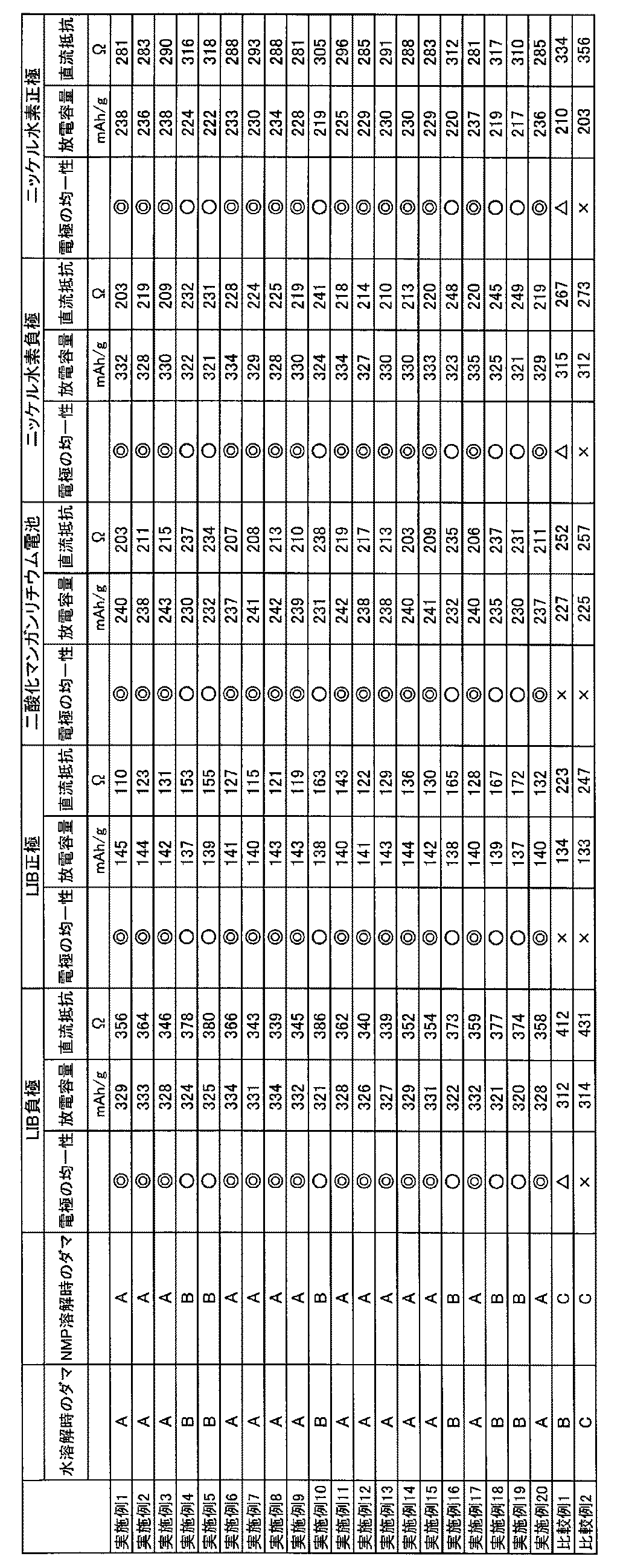
- the uniformity of the electrodes was evaluated by the method described above. The results are summarized in Table 3 below.
- the obtained electrode can be used not only for a lithium manganese dioxide battery but also for an alkaline dry battery or the like.
- the positive electrode for the battery obtained as described above was transferred to a glove box (manufactured by Miwa Seisakusho Co., Ltd.) in an argon gas atmosphere.
- Metallic lithium foil (thickness 0.2 mm, ⁇ 16 mm) is used for the negative electrode, polypropylene (Cellguard # 2400, made by Polypore) is used for the separator, and ethylene hexafluorophosphate (LiPF 6) is used as the electrolytic solution.
- the solid content in the binder aqueous solution was 3 parts by mass
- the solid content of the hydrogen storage alloy was 95 parts by mass
- the solid content in the binder aqueous solution was 3 parts by mass
- the solid content of nickel hydroxide was 95 parts by mass
- a coin battery was manufactured using the negative electrode and positive electrode for the nickel-metal hydride battery obtained as described above.
- a polypropylene-based separator (Cellguard # 2400, manufactured by Polypore) was used, and an alkaline electrolytic solution containing NaOH was injected as an electrolytic solution.
- an aqueous solution containing NaOH at 7.5 mol / L was used as the alkaline electrolytic solution.
- a coin battery (2032 type) was manufactured with such a configuration. With respect to the produced coin battery, the discharge capacity and the DC resistance value were measured by the method described above. The results are summarized in Table 3 below.
- Example 1 Production of resin powder 1 of PVA1 112.5 kg of vinyl acetate and 37.5 kg of methanol (37.5 kg) in a 250 L reactor equipped with a stirrer, a reflux cooling tube, a nitrogen introduction tube, and an initiator addition port. Vinyl acetate (75% by mass: methanol: 25% by mass) was charged, and the inside of the system was replaced with nitrogen for 30 minutes while bubbling with nitrogen. When the temperature of the reactor was started and the internal temperature reached 60 ° C., 35 g of 2,2'-azobisisobutyronitrile (AIBN) was added to start the polymerization, and the polymerization rate became 50%. By the way, it was cooled and the polymerization was stopped.
- AIBN 2,2'-azobisisobutyronitrile
- the solid content concentration at the time of stopping the polymerization was 37.0%. Subsequently, the unreacted vinyl acetate monomer was removed by occasionally adding methanol at 30 ° C. under reduced pressure to obtain a methanol solution (concentration 35%) of polyvinyl acetate (PVAc). Further, 1.86 kg of an alkaline solution (10% methanol solution of sodium hydroxide) was added to 54.05 kg (20 kg of PVAc in the solution) of PVAC prepared by adding methanol to the saponification (10% methanol solution of sodium hydroxide). The PVAc concentration of the saponification solution is 30%, and the molar ratio of sodium hydroxide to the vinyl acetate unit in PVAc is 0.02 mol%).
- a gel-like substance (resin solid substance) was formed about 1 minute after the addition of the alkaline solution, and this was pulverized with a pulverizer (mixer) for 5 minutes.
- the pulverized product was left at 40 ° C. for 1 hour to allow saponification to proceed, and then 50 kg of methyl acetate was added to neutralize the remaining alkali.
- a white solid was obtained by filtration, 200 kg of methanol was added thereto, and the mixture was washed at room temperature for 3 hours. After repeating the above washing operation three times, the white solid obtained by centrifugation was left in a dryer at 65 ° C. for 2 days to obtain a crude powder of PVA1.
- the degree of polymerization of PVA1 was 1,700 and the degree of saponification was 98.5 mol%.
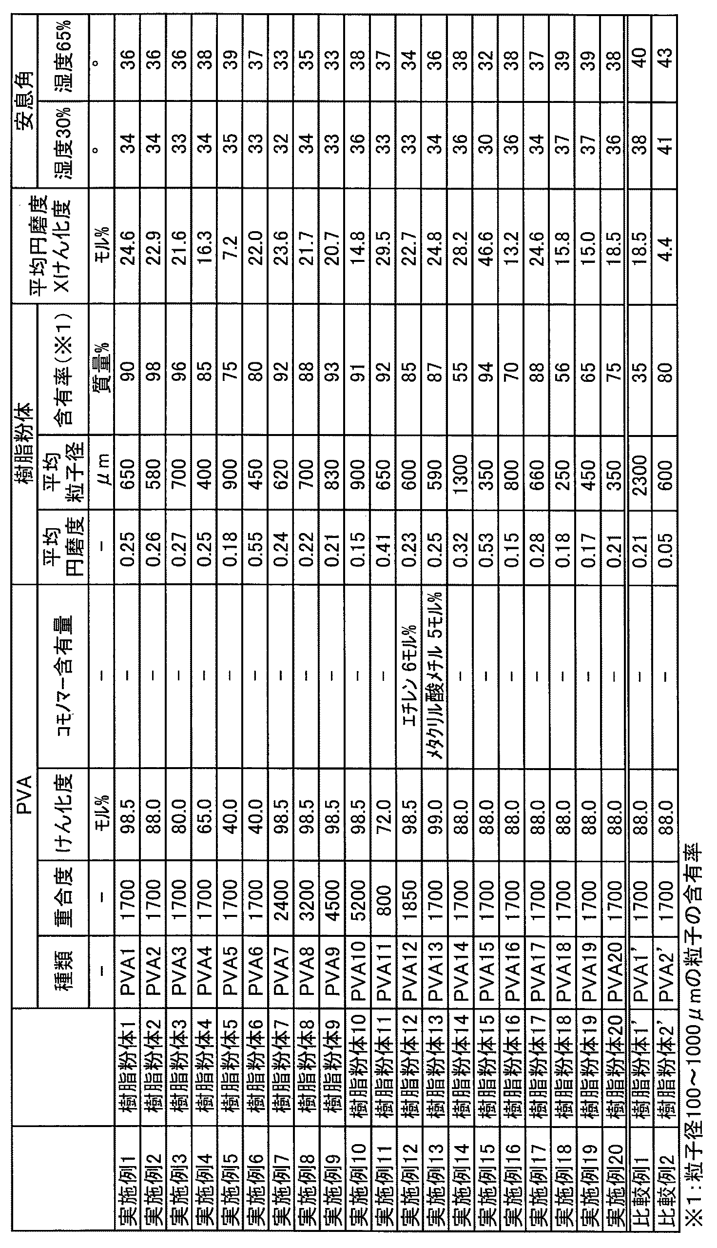
- the crude powder of PVA1 was filled in a radige mixer "FKM130D" equipped with a Becker type excavator manufactured by Chuo Kiko Co., Ltd. The surface was processed for 3 hours at a rotation speed of 160 rpm at room temperature in a nitrogen atmosphere. As a result, a resin powder 1 having an average particle diameter of 650 ⁇ m and an average roundness of 0.25 was obtained.
- Example 11 120.0 kg of vinyl acetate and 30.0 kg of methanol (80% by mass of vinyl acetate: 20% by mass of methanol) in a 250 L reactor equipped with a stirrer, a reflux cooling tube, a nitrogen introduction tube, a comonomer dropping port and an initiator addition port. ) was charged, and the inside of the system was replaced with nitrogen for 30 minutes while bubbling with nitrogen.
- the temperature of the reactor was started and the internal temperature reached 60 ° C.
- 2.5 kg of acetaldehyde and 35 g of 2,2'-azobisisobutyronitrile (AIBN) were added to start the polymerization, and the polymerization rate was increased.
- AIBN 2,2'-azobisisobutyronitrile
- the solid content concentration at the time of stopping the polymerization was 39.3%.
- the resin powder 11 of PVA11 was obtained in the same manner as in Example 1 except that the conditions shown in Table 1 were met.
- Example 12 Polymerization and saponification were carried out in the same manner as in Example 2 described in JP-A-2019-011282, and ethylene-modified PVA (PVA12) having a degree of polymerization of 1850, a degree of saponification of 98.5 mol% and an ethylene unit content of 6 mol% was carried out. Coarse powder was obtained.
- the resin powder 12 of PVA12 was obtained in the same manner as in Example 1 except that the conditions shown in Table 1 were met.
- Example 13 112.5 kg of vinyl acetate and 37.5 g of methanol (75% by mass of vinyl acetate: 25% by mass of methanol) in a 250 L reactor equipped with a stirrer, a reflux cooling tube, a nitrogen introduction tube, a comonomer dropping port and an initiator addition port. ), And 220 ml of a methanol solution in which methyl methacrylate was dissolved in 24% by mass was charged, and the inside of the system was replaced with nitrogen for 30 minutes while subjecting to nitrogen bubbling.
- Example 14 The resin powder 14 of PVA14 was obtained in the same manner as in Example 2 except that the pulverization time by the pulverizer was shortened to 2 minutes and the pulverization was performed coarser than in Example 1.
- Example 17 A resin powder 17 or the like of PVA17 was obtained in the same manner as in Example 2 except that the surface processing was performed by the apparatus shown in Table 1 instead of the Ladyge mixer.
- Example 20 The resin powder 20 of PVA20 and the like were obtained in the same manner as in Example 2 except that the crushing time by the crusher was lengthened to 10 minutes, the crushing time was finer than that in Example 1, and the surface processing treatment by the Ladyge mixer was not performed.
Landscapes
- Chemical & Material Sciences (AREA)
- Chemical Kinetics & Catalysis (AREA)
- Engineering & Computer Science (AREA)
- Electrochemistry (AREA)
- General Chemical & Material Sciences (AREA)
- Materials Engineering (AREA)
- Manufacturing & Machinery (AREA)
- Power Engineering (AREA)
- Health & Medical Sciences (AREA)
- Medicinal Chemistry (AREA)
- Polymers & Plastics (AREA)
- Organic Chemistry (AREA)
- Microelectronics & Electronic Packaging (AREA)
- Battery Electrode And Active Subsutance (AREA)
Abstract
Description
本発明は、蓄電デバイス電極に適したバインダー、バインダー溶液、蓄電デバイス電極スラリー、蓄電デバイス電極および蓄電デバイスに関する。
[1] 水溶性樹脂粉体を含むバインダーであって、
該水溶性樹脂粉体は、平均粒子径が100~2,000μmの粒子から構成され、
該水溶性樹脂粉体に含まれる粒子径100~1,000μmの粒子から任意に抽出した50個の粒子に関して、各粒子の下記式(1)

riは粒子の角毎の曲率半径であり、
Rは粒子の最大内接円の半径であり、
Nは粒子が有する角の数であり、
但し、粒子の角の数が9以上である場合、曲率半径の小さい順に8個の角の曲率半径を採用し、Nは8とする]
で表される円磨度Pの平均値PAが0.1~0.8である、バインダー。
[2] 前記水溶性樹脂はビニルアルコール系重合体である、[1]に記載のバインダー。
[3] 前記ビニルアルコール系重合体の粘度平均重合度は200~5,000であり、けん化度は35~99.99モル%である、[1]又は[2]に記載のバインダー。
[4] 下記式(2)
PA×S≧18 (2)
[式(2)中、PAは前記定義と同じであり、Sはビニルアルコール系重合体のけん化度(モル%)である]
を満たし、該水溶性樹脂粉体は平均粒子径が100~1,000μmである、請求項1~3のいずれかに記載のバインダー。
[5] 前記水溶性樹脂粉体において、粒子径100~1,000μmの粒子の含有率は50質量%以上である、[1]~[4]のいずれかに記載のバインダー。
[6] [1]~[5]のいずれかに記載のバインダーを含む蓄電デバイス電極。
[7] [1]~[5]のいずれかに記載のバインダーと水とを含む蓄電デバイス電極用バインダー溶液。
[8] N-メチル-2-ピロリドンを含む、[7]に記載の蓄電デバイス電極用バインダー溶液。
[9] [7]または[8]に記載の蓄電デバイス電極用バインダー溶液と活物質とを含む、蓄電デバイス電極スラリー。
[10] 前記バインダーの含有量は、前記活物質100質量部に対して0.1質量部以上20質量部以下である、[9]に記載の蓄電デバイス電極スラリー。
[11] [9]または[10]に記載の蓄電デバイス電極スラリーの硬化体と集電体とを含む、蓄電デバイス電極。
[12] [11]に記載の蓄電デバイス電極を含む、蓄電デバイス。
[13] 水溶性樹脂を含む樹脂固形物を粉砕することにより、該水溶性樹脂の粗粉体を得る工程、及び
該粗粉体を構成する粒子の表面を加工する工程
を含む、[1]~[5]のいずれかに記載のバインダーの製造方法。
本発明のバインダーは、水溶性樹脂粉体を含む。この粉体は、平均粒子径が100~2,000μmの粒子から構成され、該水溶性樹脂粉体に含まれる粒子径100~1,000μmの粒子から任意に抽出した50個の粒子に関して、各粒子の式(1)

riは粒子の角毎の曲率半径であり、
Rは粒子の最大内接円の半径であり、
Nは粒子が有する角の数であり、
但し、粒子の角の数が9以上である場合、曲率半径の小さい順に8個の角の曲率半径を採用し、Nは8とする]
で表される円磨度Pの平均値PA(以下、「平均円磨度」とも称する)が0.1~0.8である。
粘度平均重合度=([η]×1,0000/8.29)(1/0.62)

riは粒子の角毎の曲率半径であり、
Rは粒子の最大内接円の半径であり、
Nは粒子が有する角の数であり、
但し、粒子の角の数が9以上である場合、曲率半径の小さい順に8個の角の曲率半径を採用し、Nは8とする]
PA×S≧18 (2)
式(2)中、PAは円磨度Pの平均値である。SはPVAのけん化度(モル%)である。
本発明における水溶性樹脂粉体の製造方法は特に制限されないが、例えば以下の方法が好ましく用いられる。すなわち、本発明の一実施形態において、水溶性樹脂粉体の製造方法は、
水溶性樹脂を含む樹脂固形物を粉砕することにより、該水溶性樹脂の粗粉体を得る工程(工程B)、及び
該粗粉体に含まれる粒子の表面を加工する工程(工程C)
を含む。
工程Aは、例えば、重合工程、けん化工程等を含むことができる。
工程Bでは、PVA等の水溶性樹脂を含む樹脂固形物を粉砕する。これにより水溶性樹脂を含む粗粉体が得られる。上記粉砕は、公知の粉砕機により行うことができる。粉砕機としては、得られる粗粉体、ひいては最終的に得られる樹脂粉体を構成する粒子の平均粒子径等を調整するために、粉砕強度等の粉砕の程度を制御可能な装置が好ましい。粉砕強度の調整以外に、処理時間等によっても得られる粗粉体を構成する粒子の平均粒子径等を制御することができる。粗粉体を構成する粒子の平均粒子径は限定されるものではないが、後述する工程Cでの表面加工を行う場合は、該工程による粒度低下を考慮に入れて最終的に得られる樹脂粉体の平均粒子径以上に設定することが好ましい。例えば、粗粉体を構成する粒子の平均粒子径を100~3000μmに設定することで所望の平均粒子径を有する樹脂粉体が最終的に得られる。なお、得られた粗粉体に対して、再度けん化処理を行ってもよい。また、得られた粗粉体に対して、酢酸ナトリウム等の不純物、副生成物等を低減するための洗浄処理、及び揮発分を低減するための乾燥処理等を行ってもよい。粉砕前の樹脂固形物に対して、洗浄処理や乾燥処理を行ってもよい。
工程Cでは、粗粉体を構成する粒子の表面を加工する。PVA等の水溶性樹脂を含む樹脂固形物を破砕した場合、通常、得られる粗粉体は非常に角が尖った形状となる。そこで、工程Cにより、角を丸め、平均円磨度が所定範囲の水溶性粉体を効率的に得ることができる。
本発明のバインダーは、バインダーの溶液状態における粘度を調整する材料をさらに含有してよい。粘度を調整する材料としては、例えば、クエン酸、酒石酸、アスパラギン酸等の多価塩基酸およびその塩、その縮合物、フュームドシリカ、アルミナ等の無機物が挙げられる。これらの添加量は、特に限定されないが、通常、PVA100質量部に対して、好ましくは0.01質量部以上10質量部以下、より好ましくは、0.02質量部以上8質量部以下、さらに好ましくは、0.05質量部以上5質量部以下である。かかる粘度を調整する材料は、より多く含有させる程、本発明のバインダーの溶液状態における粘度を増加させることができる。無機物は、より粒径が小さいものを含有させるほど、バインダーの溶液状態における粘度を増加させ易い。
本発明の一実施形態としての蓄電デバイス電極スラリーは、前述のバインダー溶液と活物質とを含む。
本発明の一実施形態としての蓄電デバイス電極は、前述のスラリーの硬化体と集電体とを含む。スラリーの硬化体は、スラリー中の溶媒を乾燥等により除去して得られる硬化物である。
本発明の一実施形態としての蓄電デバイスは、前述の蓄電デバイス電極を負極および/または正極として含む。
PVAの粘度平均重合度はJIS K6726:1994に準じて測定した。具体的には、PVAのけん化度が99.5モル%未満の場合には、けん化度99.5モル%以上になるまでけん化し、得られたPVAについて、水中、30℃で測定した極限粘度[η](リットル/g)を用いて下記式により粘度平均重合度を求めた。
粘度平均重合度=([η]×1,0000/8.29)(1/0.62)
PVA(変性PVAを含む)のけん化度は、JIS K6726:1994に記載の方法により求めた。
JIS標準ふるいを使用して、JIS K7369:2009に記載の方法により樹脂粉体の平均粒子径、及び、粒子径100~1,000μm(又は、ふるい網に基づく粒子径106~1,000μm)の粒子の含有率を求めた。
上記したふるい分けによって粒子径100~1,000μm(又は、ふるい網に基づく粒子径106~1,000μm)の粒子を選別し、これらの粒子の中から任意の50個を抽出した。これらの粒子に対して、株式会社キーエンス製デジタルマイクロスコープVHX-900を用いた拡大率100倍の画像に基づき、曲率半径ri及び最大内接円の半径Rを求め、各粒子の円磨度Pを求めた。50個の粒子の円磨度Pの平均値PAを求め、平均円磨度とした。
樹脂粉体を20℃湿度30%又は20℃湿度65%の雰囲気下で1週間調湿した。その後、株式会社セイシン企業製マルチテスターMT-1001を用いて、樹脂粉体の安息角を測定した。安息角は、JIS 9301-2-2:1999に記載の方法に沿って測定した。なお、安息角が小さい樹脂粉体ほど、配管やサイロ内で粒子が融着し、凝集物が生じにくいことを発明者らは確認している。
樹脂粉体の溶媒(水またはNMP)への溶解性を確認するため、PVA5質量部に水またはNMP95質量部を加えて攪拌しながら95℃に昇温し、4時間加熱攪拌を行い、PVAの溶解の様子を目視で観察した。冷却後に目開き3mmの金網に通し、以下の基準に従って、溶解性の評価を行った。評価がAのものに関しては、バインダーとして使用した場合、電極の均一性を高めることができる。
A:金網上に残留物が確認されない。
B:金網上に透明なゲル状のダマが確認される。
C:金網上に不透明なゲル状のダマが確認される。
後述する各実施例および比較例で作製した負極および正極の均一性(均質性)を評価するため、電池用塗工電極の膜厚ばらつきを指標とし、電極4枚、各3点ずつ測定を行った。以下の基準に従って、◎、○、△、×の判定をした。評価が◎、○のものは放電容量、直流抵抗が優れ、評価が◎のものが特に優れる。
◎:平均膜厚に対してばらつきが1μm以下
○:平均膜厚に対してばらつきが1μmより大きく、2μm以下
△:平均膜厚に対してばらつきが2μmより大きく、3μm以下
×:平均膜厚に対してばらつきが3μmより大きい
後述する各実施例および比較例で作製したコイン電池について、市販の充放電試験機(TOSCAT3100、東洋システム製)を用いて試験を実施した。初期充電後に0.1mAの電流を3秒流したときの抵抗値を直流抵抗とした。充電では、リチウム電位に対して0.01Vまで0.2C(約1mA/cm2)の定電流充電を行い、さらにリチウム電位に対して0.01Vの定電圧充電を0.02mAの電流となるまで行った。放電では、リチウム電位に対して1.5Vまで0.2C(約0.5mA/cm2)の定電流放電を行った。コイン電池を25℃の恒温槽に置き、上述の条件で、初期充放電を実施し、放電容量、直流抵抗を測定した。
後述する各実施例および比較例で作製したコイン電池について、市販の充放電試験機(TOSCAT3100、東洋システム製)を用いて試験を実施した。初期充電後に0.1mAの電流を3秒流したときの抵抗値を直流抵抗とした。充電では、リチウム電位に対して4.2Vまで0.2C(約1mA/cm2)の定電流充電を行った。放電では、リチウム電位に対して0.2C(約0.5mA/cm2)の定電流放電を3Vまで行った。コイン電池を25℃の恒温槽に置き、上述の条件で、初期充放電を実施し、放電容量、直流抵抗を測定した。
後述する各実施例および比較例で作製したコイン電池について、市販の充放電試験機(TOSCAT3100、東洋システム製)を用いて試験を実施した。放電前に0.1mAの電流を3秒流したときの抵抗値を直流抵抗値とした。電池電圧が3.2Vとなるように予備放電させ、その後に定抵抗放電(15kΩ)を行い、2.0Vまでの放電容量を測定した。
後述する各実施例および比較例で作製したコイン電池について、市販の充放電試験機(TOSCAT3100、東洋システム製)を用いて試験を実施した。コイン電池を25℃の恒温槽に置き、0.2Cで充電を行った後、0.4Cで電池の電圧が1.0Vになるまで放電させる充放電作業を5回繰り返し、初期活性化を行った。初期活性化後に0.1mAの電流を3秒流したときの抵抗値を直流抵抗値とした。初期活性化後のコイン電池を0.1Cで充電し、0.2Cで電池の電圧が1.0Vになるまで放電したときの容量を測定し、放電容量とした。
前述の固形分濃度5質量%のバインダー水溶液、負極活物質としての人造黒鉛(FSN-1、中国杉杉製)、および導電助剤(導電付与剤)としてのSuper-P(ティムカル社製)を専用容器に投入し、遊星攪拌器(ARE-250、シンキー株式会社製)を用いて混練し、負極用スラリーを調製した。投入の際、バインダー水溶液中の固形分が3質量部、人造黒鉛の固形分が96質量部、Super-Pの固形分が1質量部となるようにした。すなわち、負極用スラリー中の活物質と導電助剤とバインダーとの組成比は、固形分として、黒鉛粉末:導電助剤:バインダー=96:1:3(質量比)である。
前述したように得られた負極用スラリーを、バーコーター(T101、松尾産業株式会社製)を用いて銅箔(CST8G、福田金属箔粉工業株式会社製)の集電体上に塗工した。80℃で30分間にわたり、熱風乾燥機で一次乾燥後、ロールプレス(宝泉株式会社製)を用いて圧延処理を行なった。その後、電池用電極(φ14mm)として打ち抜いた後、140℃で3時間にわたり、減圧条件の二次乾燥によってコイン電池用負極を作製した。作製したコイン電池用負極について、前述した方法で電極の均一性の評価を行った。結果は、後の表3にまとめて示す。
前述したように得られた電池用負極を、アルゴンガス雰囲気下のグローブボックス(美和製作所株式会社製)に移送した。正極には金属リチウム箔(厚さ0.2mm、φ16mm)を用い、セパレーターにはポリプロピレン系(セルガード#2400、ポリポア製)を用い、電解液には六フッ化リン酸リチウム(LiPF6)についてエチレンカーボネート(EC)およびエチルメチルカーボネート(EMC)にビニレンカーボネート(VC)を添加した混合溶媒系(1M-LiPF6、EC/EMC=3/7vol%、VC2質量%)を用いて注入した。かかる構成にて、コイン電池(2032タイプ)を作製した。作製したコイン電池について、前述した方法で放電容量および直流抵抗値の測定を行った。結果は、後の表3にまとめて示す。
さらに、前述の固形分濃度約5質量%のバインダーNMP溶液、正極活物質としてのNCM(日本化学工業社製、「セルシードC-5H」)、および導電助剤(導電付与剤)としてのSuper-P(ティムカル社製)を専用容器に投入し、遊星攪拌器(ARE-250、シンキー株式会社製)を用いて混練し、正極用スラリーを調製した。投入の際、バインダーNMP溶液中の固形分が3質量部、NCMが95質量部、Super-Pの固形分が2質量部となるようにした。すなわち、正極用スラリー中の活物質と導電助剤とバインダーとの組成比は、固形分として、NCM粉末:導電助剤:バインダー=95:2:3(質量比)である。
前述したように得られた正極用スラリーを、バーコーター(T101、松尾産業株式会社製)を用いてアルミニウム箔(CST8G、福田金属箔粉工業株式会社製)の集電体上に塗工した。80℃で30分間にわたり、熱風乾燥機で一次乾燥後、ロールプレス(宝泉株式会社製)を用いて圧延処理を行なった。その後、電池用電極(φ14mm)として打ち抜いた後、140℃で3時間にわたり、減圧条件の二次乾燥によってコイン電池用正極を作製した。作製したコイン電池用正極について、前述した方法で電極の均一性の評価を行った。結果は、後の表3にまとめて示す。
前述したように得られた電池用正極を、アルゴンガス雰囲気下のグローブボックス(美和製作所株式会社製)に移送した。負極には金属リチウム箔(厚さ0.2mm、φ16mm)を用い、セパレーターにはポリプロピレン系(セルガード#2400、ポリポア製)を用い、電解液には六フッ化リン酸リチウム(LiPF6)についてエチレンカーボネート(EC)およびエチルメチルカーボネート(EMC)にビニレンカーボネート(VC)を添加した混合溶媒系(1M-LiPF6、EC/EMC=3/7vol%、VC2質量%)を用いて注入した。かかる構成にて、コイン電池(2032タイプ)を作製した。作製したコイン電池について、前述した方法で放電容量および直流抵抗値の測定を行った。結果は、後の表3にまとめて示す。
前述の固形分濃度5質量%のバインダー水溶液、正極活物質としての二酸化マンガン、および導電助剤(導電付与剤)としてのSuper-P(ティムカル社製)を専用容器に投入し、遊星攪拌器(ARE-250、シンキー株式会社製)を用いて混練し、正極用スラリーを調製した。投入の際、バインダー水溶液中の固形分が3質量部、二酸化マンガンの固形分が95質量部、Super-Pの固形分が2質量部となるようにした。すなわち、正極用スラリー中の活物質と導電助剤とバインダーとの組成比は、固形分として、二酸化マンガン粉末:導電助剤:バインダー=95:2:3(質量比)である。なお、得られたスラリーは二酸化マンガンリチウム電池に限らず、アルカリ乾電池などにも使用可能である。
前述したように得られた正極用スラリーを、バーコーター(T101、松尾産業株式会社製)を用いてアルミニウム箔(CST8G、福田金属箔粉工業株式会社製)の集電体上に塗工した。80℃で30分間にわたり、熱風乾燥機で一次乾燥後、ロールプレス(宝泉株式会社製)を用いて圧延処理を行なった。その後、電池用電極(φ14mm)として打ち抜いた後、140℃で3時間にわたり、減圧条件の二次乾燥によってコイン電池用正極を作製した。作製したコイン電池用正極について、前述した方法で電極の均一性の評価を行った。結果は、後の表3にまとめて示す。なお、得られた電極は二酸化マンガンリチウム電池に限らず、アルカリ乾電池などにも使用可能である。
前述したように得られた電池用正極を、アルゴンガス雰囲気下のグローブボックス(美和製作所株式会社製)に移送した。負極には金属リチウム箔(厚さ0.2mm、φ16mm)を用い、セパレーターにはポリプロピレン系(セルガード#2400、ポリポア製)を用い、電解液には六フッ化リン酸リチウム(LiPF6)についてエチレンカーボネート(EC)およびエチルメチルカーボネート(EMC)にビニレンカーボネート(VC)を添加した混合溶媒系(1M-LiPF6、EC/EMC=3/7vol%、VC2質量%)を用いて注入した。かかる構成にて、コイン電池(2032タイプ)を作製した。作製したコイン電池について、前述した方法で放電容量および直流抵抗値の測定を行った。結果は、後の表3にまとめて示す。
前述の固形分濃度5質量%のバインダー水溶液、負極活物質としての水素吸蔵合金、および導電助剤(導電付与剤)としてのSuper-P(ティムカル社製)を専用容器に投入し、遊星攪拌器(ARE-250、シンキー株式会社製)を用いて混練し、負極用スラリーを調製した。投入の際、バインダー水溶液中の固形分が3質量部、水素吸蔵合金の固形分が95質量部、Super-Pの固形分が2質量部となるようにした。すなわち、負極用スラリー中の活物質と導電助剤とバインダーとの組成比は、固形分として、水素吸蔵合金:導電助剤:バインダー=95:2:3(質量比)である。
前述したように得られた負極用スラリーを、バーコーター(T101、松尾産業株式会社製)を用いて表面にニッケルメッキを施した鉄製パンチングメタル(厚み60μm、孔径1.2mm、開孔率40%)の集電体上に塗工した。80℃で30分間にわたり、熱風乾燥機で一次乾燥後、ロールプレス(宝泉株式会社製)を用いて圧延処理を行なった。その後、電池用電極(φ14mm)として打ち抜いた後、140℃で3時間にわたり、減圧条件の二次乾燥によってコイン電池用負極を作製した。作製したコイン電池用負極について、前述した方法で電極の均一性の評価を行った。結果は、後の表3にまとめて示す。
前述の固形分濃度5質量%のバインダー水溶液、正極活物質としての水酸化ニッケル、および導電助剤(導電付与剤)としてのSuper-P(ティムカル社製)を専用容器に投入し、遊星攪拌器(ARE-250、シンキー株式会社製)を用いて混練し、正極用スラリーを調製した。投入の際、バインダー水溶液中の固形分が3質量部、水酸化ニッケルの固形分が95質量部、Super-Pの固形分が2質量部となるようにした。すなわち、正極用スラリー中の活物質と導電助剤とバインダーとの組成比は、固形分として、水酸化ニッケル:導電助剤:バインダー=95:2:3(質量比)である。
前述したように得られた正極用スラリーを、バーコーター(T101、松尾産業株式会社製)を用いてニッケル発泡体(面密度(目付)約300g/m2、厚み約1.0mm)の集電体上に塗工した。80℃で30分間にわたり、熱風乾燥機で一次乾燥後、ロールプレス(宝泉株式会社製)を用いて圧延処理を行なった。その後、電池用電極(φ14mm)として打ち抜いた後、140℃で3時間にわたり、減圧条件の二次乾燥によってコイン電池用正極を作製した。作製したコイン電池用正極について、前述した方法で電極の均一性の評価を行った。結果は、後の表3にまとめて示す。
前述したように得られたニッケル水素電池用負極と正極を使用し、コイン電池を作製した。セパレーターにはポリプロピレン系(セルガード#2400、ポリポア製)を用い、電解液としてNaOHを含むアルカリ電解液を注入した。アルカリ電解液としては、NaOHを7.5mol/Lで含む水溶液を使用した。かかる構成にて、コイン電池(2032タイプ)を作製した。作製したコイン電池について、前述した方法で放電容量および直流抵抗値の測定を行った。結果は、後の表3にまとめて示す。
撹拌機、還流冷却管、窒素導入管、及び開始剤の添加口を備えた250Lの反応器に、酢酸ビニル112.5kg及びメタノール37.5kg(酢酸ビニル75質量%:メタノール25質量%)を仕込み、窒素バブリングをしながら30分間系内を窒素置換した。反応器の昇温を開始し、内温が60℃となったところで、2,2’-アゾビスイソブチロニトリル(AIBN)35gを添加し重合を開始し、重合率が50%となったところで冷却し、重合を停止した。重合停止時の固形分濃度は37.0%であった。続いて30℃、減圧下でメタノールを時々添加しながら未反応の酢酸ビニルモノマーの除去を行い、ポリ酢酸ビニル(PVAc)のメタノール溶液(濃度35%)を得た。さらに、これにメタノールを加えて調製したPVAcのメタノール溶液54.05kg(溶液中のPVAc20kg)に、1.86kgのアルカリ溶液(水酸化ナトリウムの10%メタノール溶液)を添加してけん化を行った(けん化溶液のPVAc濃度30%、PVAc中の酢酸ビニルユニットに対する水酸化ナトリウムのモル比0.02モル%)。アルカリ溶液を添加後約1分でゲル状物(樹脂固形物)が生成したので、これを粉砕機(ミキサー)にて5分間粉砕した。粉砕物を40℃で1時間放置してけん化を進行させた後、酢酸メチル50kgを加えて残存するアルカリを中和した。フェノールフタレイン指示薬を用いて中和が終了したことを確認した後、濾別して白色固体を得、これにメタノール200kgを加えて室温で3時間放置洗浄した。上記の洗浄操作を3回繰り返した後、遠心脱液して得られた白色固体を乾燥機中65℃で2日間放置してPVA1の粗粉体を得た。PVA1の重合度は1,700、けん化度は98.5モル%であった。
次にPVA1の粗粉体を中央機工株式会社製ベッカー型ショベルを搭載したレーディゲミキサー「FKM130D」に充填した。窒素雰囲気の室温下、回転速度160rpmで3時間の表面加工処理を行った。これにより、平均粒子径650μm、平均円磨度0.25の樹脂粉体1が得られた。
表1に記載の条件としたこと以外は実施例1と同様にして、PVA2の樹脂粉体2等を得た。
撹拌機、還流冷却管、窒素導入管、コモノマー滴下口及び開始剤の添加口を備えた250Lの反応器に、酢酸ビニル120.0kg及びメタノール30.0kg(酢酸ビニル80質量%:メタノール20質量%)を仕込み、窒素バブリングをしながら30分間系内を窒素置換した。反応器の昇温を開始し、内温が60℃となったところで、アセトアルデヒド2.5kg及び2,2’-アゾビスイソブチロニトリル(AIBN)35gを添加し重合を開始し、重合率が50%となったところで冷却し、重合を停止した。重合停止時の固形分濃度は39.3%であった。以下、表1に記載の条件としたこと以外は実施例1と同様にして、PVA11の樹脂粉体11を得た。
特開2019-011282号公報に記載の実施例2と同様の方法で重合及びけん化を行い、重合度1850、けん化度98.5モル%、エチレン単位含有量6モル%のエチレン変性PVA(PVA12)の粗粉体を得た。以下、表1に記載の条件としたこと以外は実施例1と同様にして、PVA12の樹脂粉体12を得た。
撹拌機、還流冷却管、窒素導入管、コモノマー滴下口及び開始剤の添加口を備えた250Lの反応器に、酢酸ビニル112.5kg、メタノール37.5g(酢酸ビニル75質量%:メタノール25質量%)、及び24質量%でメタクリル酸メチルを溶解したメタノール溶液220mlを仕込み、窒素バブリングをしながら30分間系内を窒素置換した。反応器の昇温を開始し、内温が60℃となったところで、2,2’-アゾビスイソブチロニトリル(AIBN)25gを添加し重合を開始し、上記メタクリル酸メチルのメタノール溶液11Lを逐次投入しながら、重合率が40%となったところで冷却し、重合を停止した。重合停止時の固形分濃度は28.0%であった。以下、表1に記載の条件としたこと以外は実施例1と同様にして、PVA13の樹脂粉体13を得た。
粉砕機による粉砕時間を2分間と短くし、実施例1よりも粗く行ったこと以外は実施例2と同様にして、PVA14の樹脂粉体14を得た。
レーディゲミキサーに代えて、表1に記載の装置で表面加工処理を行ったこと以外は実施例2と同様にして、PVA17の樹脂粉体17等を得た。
粉砕機による粉砕時間を10分間と長くし、実施例1よりも細かく行い、レーディゲミキサーによる表面加工処理を行わなかったこと以外は実施例2と同様にして、PVA20の樹脂粉体20等を得た。
粉砕機による粉砕時間を1分間と短くし、実施例14よりもさらに粗く行ったこと以外は実施例2と同様にして、PVA1’の樹脂粉体1’を得た。
レーディゲミキサーによる表面加工処理を行わなかったこと以外は実施例2と同様にして、PVA2’の樹脂粉体2’を得た。
実施例1~20及び比較例1~2で得られた各樹脂粉体について、上記方法にて、20℃湿度30%及び20℃湿度65%の雰囲気下で調湿後の安息角を測定した。測定結果を表2に示す。

Claims (13)
- 水溶性樹脂粉体を含むバインダーであって、
該水溶性樹脂粉体は、平均粒子径が100~2,000μmの粒子から構成され、
該水溶性樹脂粉体に含まれる粒子径100~1,000μmの粒子から任意に抽出した50個の粒子に関して、各粒子の下記式(1)

riは粒子の角毎の曲率半径であり、
Rは粒子の最大内接円の半径であり、
Nは粒子が有する角の数であり、
但し、粒子の角の数が9以上である場合、曲率半径の小さい順に8個の角の曲率半径を採用し、Nは8とする]
で表される円磨度Pの平均値PAが0.1~0.8である、バインダー。 - 前記水溶性樹脂はビニルアルコール系重合体である、請求項1に記載のバインダー。
- 前記ビニルアルコール系重合体の粘度平均重合度は200~5,000であり、けん化度は35~99.99モル%である、請求項1又は2に記載のバインダー。
- 下記式(2)
PA×S≧18 (2)
[式(2)中、PAは前記定義と同じであり、Sはビニルアルコール系重合体のけん化度(モル%)である]
を満たし、該水溶性樹脂粉体は平均粒子径が100~1,000μmである、請求項1~3のいずれかに記載のバインダー。 - 前記水溶性樹脂粉体において、粒子径100~1,000μmの粒子の含有率は50質量%以上である、請求項1~4のいずれかに記載のバインダー。
- 請求項1~5のいずれかに記載のバインダーを含む蓄電デバイス電極。
- 請求項1~5のいずれかに記載のバインダーと水とを含む蓄電デバイス電極用バインダー溶液。
- N-メチル-2-ピロリドンを含む、請求項7に記載の蓄電デバイス電極用バインダー溶液。
- 請求項7または8に記載の蓄電デバイス電極用バインダー溶液と活物質とを含む、蓄電デバイス電極スラリー。
- 前記バインダーの含有量は、前記活物質100質量部に対して0.1質量部以上20質量部以下である、請求項9に記載の蓄電デバイス電極スラリー。
- 請求項9または10に記載の蓄電デバイス電極スラリーの硬化体と集電体とを含む、蓄電デバイス電極。
- 請求項11に記載の蓄電デバイス電極を含む、蓄電デバイス。
- 水溶性樹脂を含む樹脂固形物を粉砕することにより、該水溶性樹脂の粗粉体を得る工程、及び
該粗粉体を構成する粒子の表面を加工する工程
を含む、請求項1~5のいずれかに記載のバインダーの製造方法。
Priority Applications (2)
| Application Number | Priority Date | Filing Date | Title |
|---|---|---|---|
| JP2022508316A JP7708738B2 (ja) | 2020-03-16 | 2021-03-12 | 蓄電デバイス電極に適したバインダー、バインダー溶液、蓄電デバイス電極スラリー、蓄電デバイス電極および蓄電デバイス |
| CN202180021316.7A CN115210914B (zh) | 2020-03-16 | 2021-03-12 | 适合于蓄电设备电极的粘接剂、粘接剂溶液、蓄电设备电极浆料、蓄电设备电极和蓄电设备 |
Applications Claiming Priority (2)
| Application Number | Priority Date | Filing Date | Title |
|---|---|---|---|
| JP2020044897 | 2020-03-16 | ||
| JP2020-044897 | 2020-03-16 |
Publications (1)
| Publication Number | Publication Date |
|---|---|
| WO2021187366A1 true WO2021187366A1 (ja) | 2021-09-23 |
Family
ID=77772134
Family Applications (1)
| Application Number | Title | Priority Date | Filing Date |
|---|---|---|---|
| PCT/JP2021/010081 Ceased WO2021187366A1 (ja) | 2020-03-16 | 2021-03-12 | 蓄電デバイス電極に適したバインダー、バインダー溶液、蓄電デバイス電極スラリー、蓄電デバイス電極および蓄電デバイス |
Country Status (3)
| Country | Link |
|---|---|
| JP (1) | JP7708738B2 (ja) |
| CN (1) | CN115210914B (ja) |
| WO (1) | WO2021187366A1 (ja) |
Cited By (2)
| Publication number | Priority date | Publication date | Assignee | Title |
|---|---|---|---|---|
| JP7697606B1 (ja) | 2024-07-18 | 2025-06-24 | Agc株式会社 | ポリテトラフルオロエチレン系樹脂、電極合剤、電極、及び二次電池 |
| EP4528842A4 (en) * | 2022-06-13 | 2025-10-15 | Gs Yuasa Int Ltd | NEGATIVE ELECTRODE FOR ENERGY STORAGE ELEMENT AND ENERGY STORAGE ELEMENT |
Citations (2)
| Publication number | Priority date | Publication date | Assignee | Title |
|---|---|---|---|---|
| JP2016209836A (ja) * | 2015-05-12 | 2016-12-15 | 株式会社クラレ | 吸着材 |
| WO2017029902A1 (ja) * | 2015-08-14 | 2017-02-23 | 旭化成株式会社 | 電気化学素子用電極 |
Family Cites Families (3)
| Publication number | Priority date | Publication date | Assignee | Title |
|---|---|---|---|---|
| ITBO20040120A1 (it) * | 2004-02-27 | 2004-05-27 | Arcotronics Italia Spa | Procedimento per la realizzazione di componenti elettrici, di tipo elettrostatico o elettrochimico, ad accumulo di energia, macchina che attua tale procedimento e componenti secondo il procedimento |
| JP2006278182A (ja) * | 2005-03-30 | 2006-10-12 | Sanyo Electric Co Ltd | 非水電解質二次電池とその製造方法 |
| JP6917161B2 (ja) * | 2016-03-03 | 2021-08-11 | 株式会社半導体エネルギー研究所 | リチウムイオン二次電池用の正極活物質、二次電池、電池制御ユニットおよび電子機器 |
-
2021
- 2021-03-12 WO PCT/JP2021/010081 patent/WO2021187366A1/ja not_active Ceased
- 2021-03-12 CN CN202180021316.7A patent/CN115210914B/zh active Active
- 2021-03-12 JP JP2022508316A patent/JP7708738B2/ja active Active
Patent Citations (2)
| Publication number | Priority date | Publication date | Assignee | Title |
|---|---|---|---|---|
| JP2016209836A (ja) * | 2015-05-12 | 2016-12-15 | 株式会社クラレ | 吸着材 |
| WO2017029902A1 (ja) * | 2015-08-14 | 2017-02-23 | 旭化成株式会社 | 電気化学素子用電極 |
Cited By (4)
| Publication number | Priority date | Publication date | Assignee | Title |
|---|---|---|---|---|
| EP4528842A4 (en) * | 2022-06-13 | 2025-10-15 | Gs Yuasa Int Ltd | NEGATIVE ELECTRODE FOR ENERGY STORAGE ELEMENT AND ENERGY STORAGE ELEMENT |
| JP7697606B1 (ja) | 2024-07-18 | 2025-06-24 | Agc株式会社 | ポリテトラフルオロエチレン系樹脂、電極合剤、電極、及び二次電池 |
| WO2026018647A1 (ja) * | 2024-07-18 | 2026-01-22 | Agc株式会社 | ポリテトラフルオロエチレン系樹脂、電極合剤、電極、及び二次電池 |
| JP2026015157A (ja) * | 2024-07-18 | 2026-01-29 | Agc株式会社 | ポリテトラフルオロエチレン系樹脂、電極合剤、電極、及び二次電池 |
Also Published As
| Publication number | Publication date |
|---|---|
| CN115210914B (zh) | 2025-04-29 |
| JP7708738B2 (ja) | 2025-07-15 |
| CN115210914A (zh) | 2022-10-18 |
| JPWO2021187366A1 (ja) | 2021-09-23 |
Similar Documents
| Publication | Publication Date | Title |
|---|---|---|
| JP5195749B2 (ja) | リチウムイオン二次電池電極用スラリーの製造方法 | |
| CN108140839B (zh) | 非水电解质二次电池电极用粘合剂及其制造方法、以及其用途 | |
| JP5326566B2 (ja) | リチウムイオン二次電池 | |
| JP6394593B2 (ja) | リチウムイオン二次電池正極用結着材組成物、リチウムイオン二次電池正極用スラリー組成物およびその製造方法、リチウムイオン二次電池用正極の製造方法、並びに、リチウムイオン二次電池 | |
| JP3692965B2 (ja) | リチウム二次電池およびその正極の製造方法 | |
| KR102884157B1 (ko) | 비수 전해질 전지 전극 바인더, 비수 전해질 전지 전극 바인더 용액, 비수 전해질 전지 전극 슬러리, 비수 전해질 전지 전극 및 비수 전해질 전지 | |
| JP2014022039A (ja) | リチウム二次電池用負極バインダー | |
| JP2011076981A (ja) | 二次電池用正極の製造方法、二次電池正極用スラリー及び二次電池 | |
| KR101623637B1 (ko) | 전극용 슬러리 조성물 및 리튬이온 이차전지 | |
| JP7183183B2 (ja) | 非水電解質電池用バインダー、それを用いたバインダー水溶液およびスラリー組成物、並びに非水電解質電池用電極および非水電解質電池 | |
| JP7708738B2 (ja) | 蓄電デバイス電極に適したバインダー、バインダー溶液、蓄電デバイス電極スラリー、蓄電デバイス電極および蓄電デバイス | |
| CN116830318A (zh) | 负极粘合剂组合物、负极和二次电池 | |
| JP2020145062A (ja) | 二次電池用負極合剤、二次電池用負極、および二次電池 | |
| TW201840045A (zh) | 非水電解質電池用黏合劑組成物、以及使用其之非水電解質電池用黏合劑水溶液、非水電解質電池用漿體組成物、非水電解質電池用電極、及非水電解質電池 | |
| JP7807369B2 (ja) | 蓄電デバイス電極に適したバインダー、蓄電デバイス電極用バインダー溶液、蓄電デバイス電極スラリー、蓄電デバイス電極および蓄電デバイス | |
| JP4649692B2 (ja) | リチウム二次電池用正極合剤ペーストおよびリチウム二次電池 | |
| WO2012043763A1 (ja) | 蓄電デバイス用電極合剤およびその製造方法、ならびにこれを用いた蓄電デバイス用電極およびリチウムイオン二次電池 | |
| JP2021096985A (ja) | 高分子膜及び非水電解質電池 | |
| WO2023074910A1 (ja) | 蓄電デバイス用バインダー、蓄電デバイス用バインダー溶液、蓄電デバイス電極スラリー、蓄電デバイス電極及び蓄電デバイス | |
| JP2020167097A (ja) | 蓄電デバイス電極用バインダー、蓄電デバイス電極用スラリー組成物、蓄電デバイス用電極及び蓄電デバイス | |
| JP2019110126A (ja) | 非水電解質電池電極用バインダー | |
| WO2024014420A1 (ja) | 蓄電デバイス用バインダー、蓄電デバイス用バインダー溶液、蓄電デバイス電極スラリー、蓄電デバイス電極及び蓄電デバイス | |
| TWI624985B (zh) | 非化合比鈦化合物.碳複合物及其製造方法、以及負極活性物質及鋰離子二次電池 | |
| CN116724064A (zh) | 电化学元件正极用组合物、电化学元件正极用浆料组合物、电化学元件用正极以及电化学元件 | |
| JP2021096984A (ja) | 高分子膜及び非水電解質電池 |
Legal Events
| Date | Code | Title | Description |
|---|---|---|---|
| 121 | Ep: the epo has been informed by wipo that ep was designated in this application |
Ref document number: 21772608 Country of ref document: EP Kind code of ref document: A1 |
|
| ENP | Entry into the national phase |
Ref document number: 2022508316 Country of ref document: JP Kind code of ref document: A |
|
| NENP | Non-entry into the national phase |
Ref country code: DE |
|
| 122 | Ep: pct application non-entry in european phase |
Ref document number: 21772608 Country of ref document: EP Kind code of ref document: A1 |
|
| WWG | Wipo information: grant in national office |
Ref document number: 202180021316.7 Country of ref document: CN |