WO2021187356A1 - 金属空気電池システム - Google Patents
金属空気電池システム Download PDFInfo
- Publication number
- WO2021187356A1 WO2021187356A1 PCT/JP2021/010043 JP2021010043W WO2021187356A1 WO 2021187356 A1 WO2021187356 A1 WO 2021187356A1 JP 2021010043 W JP2021010043 W JP 2021010043W WO 2021187356 A1 WO2021187356 A1 WO 2021187356A1
- Authority
- WO
- WIPO (PCT)
- Prior art keywords
- electrolytic solution
- metal
- battery system
- oxygen
- air battery
- Prior art date
- Legal status (The legal status is an assumption and is not a legal conclusion. Google has not performed a legal analysis and makes no representation as to the accuracy of the status listed.)
- Ceased
Links
Images

Classifications
-
- H—ELECTRICITY
- H01—ELECTRIC ELEMENTS
- H01M—PROCESSES OR MEANS, e.g. BATTERIES, FOR THE DIRECT CONVERSION OF CHEMICAL ENERGY INTO ELECTRICAL ENERGY
- H01M12/00—Hybrid cells; Manufacture thereof
- H01M12/04—Hybrid cells; Manufacture thereof composed of a half-cell of the fuel-cell type and of a half-cell of the primary-cell type
- H01M12/06—Hybrid cells; Manufacture thereof composed of a half-cell of the fuel-cell type and of a half-cell of the primary-cell type with one metallic and one gaseous electrode
-
- H—ELECTRICITY
- H01—ELECTRIC ELEMENTS
- H01M—PROCESSES OR MEANS, e.g. BATTERIES, FOR THE DIRECT CONVERSION OF CHEMICAL ENERGY INTO ELECTRICAL ENERGY
- H01M4/00—Electrodes
- H01M4/86—Inert electrodes with catalytic activity, e.g. for fuel cells
- H01M4/90—Selection of catalytic material
- H01M4/9016—Oxides, hydroxides or oxygenated metallic salts
-
- H—ELECTRICITY
- H01—ELECTRIC ELEMENTS
- H01M—PROCESSES OR MEANS, e.g. BATTERIES, FOR THE DIRECT CONVERSION OF CHEMICAL ENERGY INTO ELECTRICAL ENERGY
- H01M4/00—Electrodes
- H01M4/86—Inert electrodes with catalytic activity, e.g. for fuel cells
- H01M4/96—Carbon-based electrodes
-
- H—ELECTRICITY
- H01—ELECTRIC ELEMENTS
- H01M—PROCESSES OR MEANS, e.g. BATTERIES, FOR THE DIRECT CONVERSION OF CHEMICAL ENERGY INTO ELECTRICAL ENERGY
- H01M50/00—Constructional details or processes of manufacture of the non-active parts of electrochemical cells other than fuel cells, e.g. hybrid cells
- H01M50/10—Primary casings; Jackets or wrappings
- H01M50/102—Primary casings; Jackets or wrappings characterised by their shape or physical structure
- H01M50/107—Primary casings; Jackets or wrappings characterised by their shape or physical structure having curved cross-section, e.g. round or elliptic
-
- H—ELECTRICITY
- H01—ELECTRIC ELEMENTS
- H01M—PROCESSES OR MEANS, e.g. BATTERIES, FOR THE DIRECT CONVERSION OF CHEMICAL ENERGY INTO ELECTRICAL ENERGY
- H01M8/00—Fuel cells; Manufacture thereof
- H01M8/04—Auxiliary arrangements, e.g. for control of pressure or for circulation of fluids
- H01M8/04082—Arrangements for control of reactant parameters, e.g. pressure or concentration
- H01M8/04201—Reactant storage and supply, e.g. means for feeding, pipes
-
- H—ELECTRICITY
- H01—ELECTRIC ELEMENTS
- H01M—PROCESSES OR MEANS, e.g. BATTERIES, FOR THE DIRECT CONVERSION OF CHEMICAL ENERGY INTO ELECTRICAL ENERGY
- H01M8/00—Fuel cells; Manufacture thereof
- H01M8/06—Combination of fuel cells with means for production of reactants or for treatment of residues
- H01M8/0662—Treatment of gaseous reactants or gaseous residues, e.g. cleaning
- H01M8/0668—Removal of carbon monoxide or carbon dioxide
-
- H—ELECTRICITY
- H01—ELECTRIC ELEMENTS
- H01M—PROCESSES OR MEANS, e.g. BATTERIES, FOR THE DIRECT CONVERSION OF CHEMICAL ENERGY INTO ELECTRICAL ENERGY
- H01M2300/00—Electrolytes
- H01M2300/0002—Aqueous electrolytes
-
- H—ELECTRICITY
- H01—ELECTRIC ELEMENTS
- H01M—PROCESSES OR MEANS, e.g. BATTERIES, FOR THE DIRECT CONVERSION OF CHEMICAL ENERGY INTO ELECTRICAL ENERGY
- H01M2300/00—Electrolytes
- H01M2300/0017—Non-aqueous electrolytes
-
- Y—GENERAL TAGGING OF NEW TECHNOLOGICAL DEVELOPMENTS; GENERAL TAGGING OF CROSS-SECTIONAL TECHNOLOGIES SPANNING OVER SEVERAL SECTIONS OF THE IPC; TECHNICAL SUBJECTS COVERED BY FORMER USPC CROSS-REFERENCE ART COLLECTIONS [XRACs] AND DIGESTS
- Y02—TECHNOLOGIES OR APPLICATIONS FOR MITIGATION OR ADAPTATION AGAINST CLIMATE CHANGE
- Y02E—REDUCTION OF GREENHOUSE GAS [GHG] EMISSIONS, RELATED TO ENERGY GENERATION, TRANSMISSION OR DISTRIBUTION
- Y02E60/00—Enabling technologies; Technologies with a potential or indirect contribution to GHG emissions mitigation
- Y02E60/10—Energy storage using batteries
Definitions
- This disclosure relates to a metal-air battery system.
- Patent Document 1 discloses a metal-air battery system in which oxygen is used as the positive electrode active material and metal is used as the negative electrode active material.
- oxygen as a positive electrode active material is dissolved in an electrolyte by bubbling air with an electrolytic solution in a tank.
- At least one embodiment of the present disclosure is an object of providing a metal-air battery system capable of increasing the discharge current density.
- the metal air battery system includes a negative electrode, a metal body electrically connected to the negative electrode, and a positive electrode, and a chamber through which an electrolytic solution flows is the negative electrode and a chamber through which the electrolytic solution flows.
- a battery device defined between the metal bodies, an oxygen separator that separates oxygen from the air, and a gas containing oxygen separated by the oxygen separator are bubbling into the electrolytic solution supplied to the chamber. It is equipped with a bubbling device that supplies while supplying.
- a gas having a higher oxygen concentration than air is bubbled to dissolve oxygen in the electrolytic solution, so that the electrolytic solution is compared with the case where air is bubbled in the electrolytic solution.
- the dissolution rate of oxygen can be increased. As a result, the discharge current density can be increased.
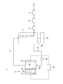
- the metal-air battery system 1 includes a battery device 2, an electrolytic solution tank 3 for storing an electrolytic solution, and an oxygen separation device 4 for separating oxygen from the air. And a bubbling device 5 that supplies a gas containing oxygen separated by the oxygen separation device 4 while bubbling into the electrolytic solution stored in the electrolytic solution tank 3.
- the battery device 2 includes a negative electrode 11, a metal body 12 electrically connected to the negative electrode 11, and a positive electrode 13, and a chamber 14 is defined between the negative electrode 11 and the metal body 12.
- Each of the negative electrode 11 and the positive electrode 13 is electrically connected to an arbitrary load 10.
- a separator 15 is provided on the surface 12a of the metal body 12 that defines the chamber 14.
- a catalyst mainly containing platinum as an active ingredient (for example, platinum-supported carbon) can be used in an acidic liquid environment.
- a catalyst containing a 3d transition metal such as iron, manganese, nickel or cobalt or an oxide thereof as an active ingredient can be used in an alkaline solution environment.
- a catalyst containing ruthenium, silver, gold, or iridium as an active ingredient can be used in both an acidic liquid environment and an alkaline liquid environment.
- a catalyst containing an organic metal complex, carbon fibers (for example, carbon nanotubes), nitrogen carbide or the like as an active ingredient can also be used.
- the electrolytic solution tank 3 and the chamber 14 can be communicated with each other by the electrolytic solution supply path 16 and the electrolytic solution return path 17.
- the electrolytic solution in the electrolytic solution tank 3 is supplied to the chamber 14 via the electrolytic solution supply path 16 and flows through the chamber 14 from the chamber 14.
- the outflowing electrolytic solution is returned to the electrolytic solution tank 3 via the electrolytic solution return path 17, so that the electrolytic solution circulates between the electrolytic solution tank 3 and the chamber 14.
- the electrolytic solution tank 3 and the chamber 14 can be communicated with each other only by the electrolytic solution supply path 16.
- the electrolytic solution supplied from the electrolytic solution tank 3 to the chamber 14 via the electrolytic solution supply path 16 flows through the chamber 14 and flows out from the chamber 14, and then flows out from the chamber 14, and then the electrolytic solution tank 3 via an outflow path (not shown). It is sent to equipment other than.
- the electrolytic solution does not circulate between the electrolytic solution tank 3 and the chamber 14.
- the pump 18 in the electrolytic solution supply path 16 the electrolytic solution in the electrolytic solution tank 3 can be supplied to the chamber 14 via the electrolytic solution supply path 16, and instead of the pump 18. It is also possible to supply the electrolytic solution by water head pressure.
- the amount of the electrolytic solution used in the configuration in which the electrolytic solution circulates between the electrolytic solution tank 3 and the chamber 14 is compared with the configuration in which the electrolytic solution does not circulate between the electrolytic solution tank 3 and the chamber 14. Can be reduced, so that the cost can be reduced.
- the configuration of the oxygen separation device 4 is not particularly limited, and an oxygen separation device having an arbitrary configuration such as a pressure fluctuation adsorption (PSA) type device, a temperature fluctuation adsorption (TSA) type device, or a membrane separation device is used. can do.
- PSA pressure fluctuation adsorption
- TSA temperature fluctuation adsorption
- membrane separation device a membrane separation device
- an aqueous electrolyte in which the electrolyte is dissolved in water or a non-aqueous electrolyte in which the electrolyte is dissolved in a non-aqueous solution such as an organic solvent can be used.
- aqueous electrolyte solution for example, an aqueous solution containing hydroxides such as potassium, sodium, lithium, barium and magnesium, chlorides, phosphates, borates, sulfates and the like as electrolytes can be used. That is, any indicator salt for imparting electrical conductivity of the aqueous solution can be used as an electrolyte.
- non-aqueous electrolytic solution for example, a liquid in which an indicator salt made of an alkali metal or the like is dissolved in a liquid such as a cyclic or chain carbonate, a cyclic or chain ester, a cyclic or chain ether, a sulfone compound, or an ionic liquid is used. can do.
- the metal body 12 is drawn so as to have a plate-like structure, but the present invention is not limited to this form, and a porous substrate plated with metal can also be used.
- a porous substrate plated with metal can also be used.
- the material of the metal body 12 zinc, iron, aluminum, lithium, sodium, potassium, copper, magnesium and the like or alloys thereof can be used.
- an aqueous electrolytic solution is used as the electrolytic solution, it is preferable to use zinc, iron, aluminum, copper or an alloy thereof or an alloy thereof as the material of the metal body 12, and a non-aqueous electrolytic solution is used as the electrolytic solution.
- the gas bubbling by the bubbling device 5 is a gas containing oxygen separated by the oxygen separation device 4
- oxygen is dissolved in the electrolytic solution by bubbling a gas having a higher oxygen concentration than air. Therefore, the dissolved oxygen concentration in the electrolytic solution can be increased as compared with the case where air is bubbled in the electrolytic solution.
- the average value of the bubble diameter of the gas can be 100 ⁇ m or less when the gas containing oxygen separated by the oxygen separation device 4 is bubbling. Since the bubble diameter and the pressure inside the bubble are inversely proportional to each other, the pressure inside the bubble increases as the bubble diameter decreases. In addition, the rate of dissolution of gas in a liquid is proportional to pressure. Therefore, the smaller the bubble diameter, the higher the dissolution rate of the gas in the liquid.
- the bubbling device 5 capable of making the average value of the bubble diameter of the gas 100 ⁇ m or less, the dissolution of oxygen in the electrolytic solution can be further enhanced as compared with the case where the gas containing oxygen is simply bubbling.
- the metal-air battery system 1 has carbon dioxide removal that removes carbon dioxide from the oxygen-containing gas separated by the oxygen separator 4 between the electrolyte tank 3 and the oxygen separator 4.
- the device 21 may be provided.
- the carbon dioxide removing device 21 may be provided on the upstream side of the oxygen separating device 4 to remove carbon dioxide from the air supplied to the oxygen separating device 4. In either case, the gas having a reduced carbon dioxide concentration can be bubbled in the electrolytic solution as compared with the case where the carbon dioxide removing device 21 is not provided.
- the configuration of the carbon dioxide removing device 21 is not particularly limited, and for example, a device having a configuration in which carbon dioxide is absorbed by a liquid absorbing liquid such as an amine aqueous solution, or a configuration in which carbon dioxide is adsorbed by a solid absorbent.
- the device can be used.
- the metal-air battery system 1 may be provided with a recovery container 22 communicating with the bottom 3a of the electrolyte tank 3.
- the oxygen separation device 4 separates oxygen from the air, and the bubbling device 5 supplies the separated oxygen-containing gas into the electrolytic solution stored in the electrolytic solution tank 3 while bubbling. As a result, oxygen is dissolved in the electrolytic solution stored in the electrolytic solution tank 3, and the dissolved oxygen concentration in the electrolytic solution is increased.
- the electrolytic solution stored in the electrolytic solution tank 3 flows into the chamber 14 via the electrolytic solution supply path 16.
- the electrolytic solution flows through the chamber 14, flows out of the chamber 14, and then returns to the electrolytic solution tank 3 via the electrolytic solution return path 17, so that the electrolytic solution circulates between the electrolytic solution tank 3 and the chamber 14.
- M is a metal atom
- the metal element constituting the metal body 12 reacts with the hydroxide in the electrolytic solution to form metallic water. As the oxide is generated, electrons are emitted to the negative electrode electrode 11.
- the metal-air battery system 1 In order to increase the discharge current density of the metal-air battery system 1, it is necessary to increase the dissolved oxygen concentration and the oxygen dissolution rate in the electrolytic solution.
- a gas having a higher oxygen concentration than air is bubbled to dissolve oxygen in the electrolytic solution, so that the dissolved oxygen concentration in the electrolytic solution is higher than that in the case of bubbling air in the electrolytic solution. Can be enhanced. As a result, the discharge current density can be increased.
- the bubbling device 5 is used so that the average value of the bubble diameter of the gas can be 100 ⁇ m or less, the discharge current density can be further increased as compared with the case where the gas containing oxygen is simply bubbling.
- the gas bubbled in the electrolytic solution stored in the electrolytic solution tank 3 is a gas containing oxygen separated from the air by the oxygen separator 4, but since the air contains carbon dioxide, this gas. There is a possibility that carbon dioxide is also mixed in. When such a gas is bubbled into the electrolytic solution, carbon dioxide is dissolved in the electrolytic solution. If carbon dioxide is dissolved in the electrolytic solution, the metal ions eluted in the electrolytic solution during discharge react with carbon dioxide, which adversely affects the battery performance.
- the carbon dioxide removing device 21 when the carbon dioxide removing device 21 is provided in the metal-air battery system 1, the gas having a reduced carbon dioxide concentration is supplied to the electrolytic solution, so that the dissolved concentration of carbon dioxide in the electrolytic solution is reduced, and the battery The risk of adverse effects on performance can be reduced.
- a part of the metal oxide which is a reaction product of a metal ion and an oxygen ion, a part of a metal carbonate which is a reaction product of a metal ion and carbon dioxide, that is, a part of a metal ion precipitate It floats in the electrolytic solution and circulates together with the electrolytic solution between the electrolytic solution tank 3 and the chamber 14. While the electrolytic solution is stored in the electrolytic solution tank 3, metal ion precipitates settle downward. If a recovery container 22 communicating with the bottom 3a of the electrolytic solution tank 3 is provided, the metal ion precipitates can be recovered in the recovery container 22, so that the recovered metal ion precipitates can be reused as the material of the metal body 12. be able to.
- the bubbling device 5 supplies the oxygen-containing gas separated by the oxygen separation device 4 into the electrolytic solution stored in the electrolytic solution tank 3 while bubbling, but the present invention is limited to this embodiment. It is not something to do.
- the bubbling device 5 may bubbling the gas into the electrolytic solution flowing through the electrolytic solution supply path 16 between the pump 18 and the chamber 14. According to this configuration, the risk of bubbling gas bubbles being sucked into the pump 18 can be reduced, so that the risk of the pump 18 failing can be reduced.
- a sufficient time for the oxygen to dissolve in the electrolytic solution can be secured, so that the electrolytic solution in which the oxygen is dissolved can be reliably supplied to the chamber. ..
- the metal-air battery system according to the second embodiment is a modification of the configuration of the battery device 2 with respect to the first embodiment.
- the same reference numerals as those of the constituent requirements of the first embodiment are designated by the same reference numerals, and detailed description thereof will be omitted.
- the battery device 2 has a cylindrical shape in which a metal body 12 and a negative electrode electrode 11 are provided so as to surround the positive electrode electrode 13. doing.
- a chamber 14 having a ring-shaped cross section is formed between the positive electrode 13 and the metal body 12.
- Electrolyte distribution flanges 31 and 32 are provided at both ends of this cylindrical shape in the axial direction. Internal spaces 31a and 32a communicating with the chamber 14 are formed inside the electrolytic solution distribution flanges 31 and 32, respectively. The internal spaces 31a and 32a communicate with the electrolytic solution supply path 16 and the electrolytic solution return path 17, respectively.
- Other configurations are the same as those in the first embodiment. It should be noted that a modified example of each configuration requirement in the first embodiment can also be applied to the second embodiment.
- the operation of dissolving oxygen in the electrolytic solution, the discharge principle of the battery device 2, and the operation when the carbon dioxide removing device 21 and the recovery container 22 are provided are the same as those of the first embodiment. Therefore, the same effect as that of the first embodiment can be obtained in the metal-air battery system 1 according to the second embodiment.
- the negative electrode 11 and the positive electrode 13 each have a flat plate shape, and one chamber 14 is formed between the metal body 12 and the positive electrode 13, but the negative electrode is shown in FIG.
- the arrangement of the electrode 11, the metal body 12, the positive electrode 13 and the chamber 14 is actually very complicated, and the flow of the electrolytic solution in the chamber 14 is also complicated.
- the battery device 2 has a cylindrical shape in which the metal body 12 and the negative electrode electrode 11 are provided so as to surround the positive electrode electrode 13. ing.
- the flow path of the electrolytic solution in the battery device 2 that is, the chamber 14 has a simple structure extending in the axial direction of the cylinder, so that the pressure loss of the electrolytic solution can be reduced, and further, the electrolytic solution can be reduced. It is possible to reduce the possibility that a gas pool is formed in the battery device 2 when a gas such as oxygen dissolved in the battery device 2 is dissipated. Further, since both ends of the cylindrical shape of the battery device 2 can be sealed, the battery device 2 can be sealed, so that the sealing property is excellent and the possibility of leakage of the electrolytic solution can be reduced.
- the battery device 2 can be charged by connecting the negative electrode 11 and the positive electrode 13 to the power source instead of the load 10 and applying a voltage between them.
- the battery device 2 can be discharged again by replacing the metal body 12 with a new one. In this case, the metal body 12 needs to be replaceably attached to the negative electrode electrode 11.
- the battery device 2 can be used as a secondary battery as in the former, or as a primary battery as in the latter.
- ⁇ Modification example of the metal-air battery system of the present disclosure> It is also possible to remove the oxygen separator 4 from each of the first and second embodiments.
- the only component of the gas used in the chamber 14 is oxygen, but the air also contains nitrogen, carbon dioxide and argon. It is preferable to remove carbon dioxide because it adversely affects the battery performance.
- nitrogen and argon are inert gases, there is a disadvantage that the oxygen concentration in the gas is low, but nitrogen and argon in the gas Even if it contains argon, it does not adversely affect the battery performance. Therefore, in the metal-air battery system 1 according to each of the first and second embodiments, it is possible to adopt a configuration in which the oxygen separation device 4 is removed and the carbon dioxide removal device 21 is provided.
- the metal body 12 and the negative electrode electrode 11 are provided so as to surround the positive electrode electrode 13, but the positive electrode 13 may be provided so as to surround the metal body 12 and the negative electrode electrode 11. ..
- the gas dissolution rate in the electrolytic solution needs to be about 6.5 ⁇ 10 -3 mol / sec.
- the bubble diameter of the supplied gas is preferably 5 ⁇ m or less.
- the conditions of the bubbles supplied to the electrolyte are defined by the critical current density of the metal-air battery system.
- the relationship between the critical current density and the bubble condition is illustrated in Table 1 below.
- the critical current density is 500 mA / cm 2
- a bubble diameter (average bubble diameter) of 10 ⁇ m is supplied to the electrolytic solution
- a bubble content of 6.4 vol% or more is required, and 5 ⁇ m.
- a bubble content of 0.8 vol% or more is required. That is, the smaller the bubble diameter, the higher the critical current density can be operated with a smaller bubble content.
- the general bubble content of minute bubbles is less than 10 vol%, it is desirable to operate with a bubble diameter in which the bubble content is less than 10 vol% depending on the operating current density and the critical current density.
- the dissolved oxygen concentration and the oxygen reduction current density were measured for each of the KOH aqueous solutions of batch cells 1 to 5.
- a low-concentration portable dissolved oxygen meter (DO-32A) manufactured by Toa DKK was used to measure the dissolved oxygen while sending the bubble-generated solution to the measuring instrument at 100 ml / min.
- the temperature of the solution at that time was 23 ° C. (however, only the batch cell 3 had a solution temperature of 22 ° C.).
- the potential sweep rate was set to 10 mV / by the linear sweep voltammetry method in a three-electrode cell with platinum with a diameter of 3 mm as the working electrode, platinum wire as the counter electrode, and Hg / HgO (1M KOH) as the reference electrode.
- the measurement was performed under the respective conditions of sec and 20 mV / sec. The results of these measurements are also shown in Table 2.
- the metal-air battery system is A chamber (14) including a negative electrode (11), a metal body (12) electrically connected to the negative electrode (11), and a positive electrode (13) through which an electrolytic solution flows is the negative electrode (11). And the battery device (2) defined between the metal bodies (12), An oxygen separator (4) that separates oxygen from the air, It is provided with a bubbling device (5) that supplies a gas containing oxygen separated by the oxygen separation device (4) while bubbling into the electrolytic solution supplied to the chamber (14).
- a gas having a higher oxygen concentration than air is bubbled to dissolve oxygen in the electrolytic solution, so that the electrolytic solution is compared with the case where air is bubbled in the electrolytic solution.
- the dissolution rate of oxygen can be increased. As a result, the discharge current density can be increased.
- the metal-air battery system according to another aspect is the metal-air battery system of [1].
- the average value of the bubble diameter of the gas supplied into the electrolytic solution by the bubbling device (5) is 100 ⁇ m or less.
- the pressure inside the bubble increases as the bubble diameter decreases.
- the rate at which a gas dissolves in a liquid is proportional to the pressure. Therefore, the smaller the bubble diameter, the higher the concentration of the gas dissolved in the liquid. According to the configuration as described in [2] above, the dissolution rate of oxygen in the electrolytic solution can be increased as compared with the case where the gas containing oxygen is simply bubbled. As a result, the discharge current density can be increased.
- the metal-air battery system according to still another aspect is the metal-air battery system of [2].
- the bubble content of the gas is less than 10 vol%.
- the dissolution rate of oxygen in the electrolytic solution can be increased as compared with the case where the gas containing oxygen is simply bubbled. As a result, the discharge current density can be increased.
- the metal-air battery system according to still another aspect is the metal-air battery system according to any one of [1] to [3].
- a carbon dioxide removing device (21) for removing carbon dioxide from the gas containing oxygen separated by the oxygen separating device (4) or the air supplied to the oxygen separating device (4) is provided.
- the metal-air battery system according to still another aspect is the metal-air battery system according to any one of [1] to [4].
- the electrolytic solution tank (3) for storing the electrolytic solution is provided.
- the bubbling device (5) supplies the gas to the electrolytic solution stored in the electrolytic solution tank (3) while bubbling.
- the metal-air battery system is the metal-air battery system according to any one of [1] to [4].
- the electrolytic solution tank (3) for storing the electrolytic solution is provided.
- the electrolytic solution circulates between the electrolytic solution tank and the chamber, the amount of the electrolytic solution used can be reduced and the cost can be reduced as compared with the case where the electrolytic solution flowing through the chamber is discarded. Can be reduced.
- the metal-air battery system according to still another aspect is the metal-air battery system of [6].
- the bubbling device (5) bubbles the gas into the electrolytic solution flowing through the electrolytic solution supply path (16) between the pump (18) and the chamber (14).
- the risk of bubbling gas bubbles being sucked into the pump can be reduced, so that the risk of pump failure can be reduced.
- the metal-air battery system according to still another aspect is the metal-air battery system according to any one of [5] to [7].
- a recovery container (22) communicating with the bottom (3a) of the electrolytic solution tank (3) is provided.
- the precipitate of metal ions eluted from the metal body can be collected in a recovery container and reused as the metal body.
- the metal-air battery system according to still another aspect is the metal-air battery system according to any one of [1] to [8].
- the battery device (2) has a cylindrical shape in which the metal body (12) is provided so as to surround the positive electrode (13).
- the flow path of the electrolytic solution in the battery device is simplified, so that the pressure loss of the electrolytic solution can be reduced, and further, when the gas such as oxygen dissolved in the electrolytic solution is dissipated, the battery is used. It is possible to reduce the possibility that a gas pool is formed in the device. Further, since both ends of the cylindrical shape of the battery device can be sealed, the battery device can be sealed, so that the sealing property is excellent and the possibility of leakage of the electrolytic solution can be reduced.
- the metal-air battery system is A chamber (14) including a negative electrode (11), a metal body (12) electrically connected to the negative electrode (11), and a positive electrode (13) through which an electrolytic solution flows is the negative electrode (11).
- the battery device (2) defined between the metal bodies (12), A carbon dioxide remover (21) that removes carbon dioxide from the air, It is provided with a bubbling device (5) that supplies a gas from which carbon dioxide has been removed from air into the electrolytic solution supplied to the chamber (14) while bubbling.
- the metal-air battery system of the present disclosure since a gas having a lower carbon dioxide concentration than air is supplied to the electrolytic solution, the dissolved concentration of carbon dioxide in the electrolytic solution is lowered, which adversely affects the battery performance.
- Electrolyte tank 3a (of electrolyte tank) Bottom 4 Oxygen separator 5 Bubbling device 11 Negative electrode 12 Metal body 13 Positive electrode 14 Chamber 16 Electrolyte supply path 17 Electrolyte return path 18 Pump 21 Carbon dioxide remover 22 Recovery container
Landscapes
- Chemical & Material Sciences (AREA)
- Chemical Kinetics & Catalysis (AREA)
- Electrochemistry (AREA)
- General Chemical & Material Sciences (AREA)
- Engineering & Computer Science (AREA)
- Manufacturing & Machinery (AREA)
- Life Sciences & Earth Sciences (AREA)
- Sustainable Development (AREA)
- Sustainable Energy (AREA)
- Materials Engineering (AREA)
- Hybrid Cells (AREA)
Priority Applications (4)
| Application Number | Priority Date | Filing Date | Title |
|---|---|---|---|
| US17/797,306 US20230066224A1 (en) | 2020-03-19 | 2021-03-12 | Metal air battery system |
| AU2021238135A AU2021238135B2 (en) | 2020-03-19 | 2021-03-12 | Metal-air battery system |
| DE112021000404.2T DE112021000404T5 (de) | 2020-03-19 | 2021-03-12 | Metall-luft-batteriesystem |
| JP2022508310A JP7423753B2 (ja) | 2020-03-19 | 2021-03-12 | 金属空気電池システム |
Applications Claiming Priority (2)
| Application Number | Priority Date | Filing Date | Title |
|---|---|---|---|
| JP2020-049139 | 2020-03-19 | ||
| JP2020049139 | 2020-03-19 |
Publications (1)
| Publication Number | Publication Date |
|---|---|
| WO2021187356A1 true WO2021187356A1 (ja) | 2021-09-23 |
Family
ID=77772125
Family Applications (1)
| Application Number | Title | Priority Date | Filing Date |
|---|---|---|---|
| PCT/JP2021/010043 Ceased WO2021187356A1 (ja) | 2020-03-19 | 2021-03-12 | 金属空気電池システム |
Country Status (5)
| Country | Link |
|---|---|
| US (1) | US20230066224A1 (https=) |
| JP (1) | JP7423753B2 (https=) |
| AU (1) | AU2021238135B2 (https=) |
| DE (1) | DE112021000404T5 (https=) |
| WO (1) | WO2021187356A1 (https=) |
Families Citing this family (1)
| Publication number | Priority date | Publication date | Assignee | Title |
|---|---|---|---|---|
| WO2025208207A1 (en) * | 2024-04-02 | 2025-10-09 | Blue-Tech Group Inc. | Improvements in metal-gas batteries and fuel cells |
Citations (7)
| Publication number | Priority date | Publication date | Assignee | Title |
|---|---|---|---|---|
| JP2008300346A (ja) * | 2007-05-01 | 2008-12-11 | Toyota Motor Corp | 空気電池システム |
| JP2011253789A (ja) * | 2010-06-04 | 2011-12-15 | Hitachi Zosen Corp | 金属空気電池 |
| JP2012028017A (ja) * | 2010-07-20 | 2012-02-09 | Aisin Seiki Co Ltd | 金属−空気電池システム |
| JP2012084261A (ja) * | 2010-10-07 | 2012-04-26 | Sumitomo Chemical Co Ltd | 空気電池 |
| JP2012230892A (ja) * | 2011-04-14 | 2012-11-22 | Sumitomo Chemical Co Ltd | 空気電池 |
| JP2014026857A (ja) * | 2012-07-27 | 2014-02-06 | Sharp Corp | 電池用電極体、電池および金属空気電池 |
| JP2015072744A (ja) * | 2013-10-01 | 2015-04-16 | 日産自動車株式会社 | 金属空気電池 |
Family Cites Families (4)
| Publication number | Priority date | Publication date | Assignee | Title |
|---|---|---|---|---|
| DE2326070C3 (de) * | 1973-05-22 | 1979-10-25 | Siemens Ag, 1000 Berlin Und 8000 Muenchen | Vorrichtung zur Entfernung von Kohlendioxid aus zum Betrieb von elektrochemischen Zellen dienender Luft |
| JP2010170819A (ja) * | 2009-01-22 | 2010-08-05 | Equos Research Co Ltd | 空気電池システム |
| US10581105B2 (en) * | 2016-03-22 | 2020-03-03 | Paul E. DuFresne | Fuel cells utilizing liquid metal alloy reducing agents and fuel cell systems including the same |
| US11374226B2 (en) * | 2018-04-24 | 2022-06-28 | Massachusetts Institute Of Technology | Corrosion mitigation of battery electrodes |
-
2021
- 2021-03-12 JP JP2022508310A patent/JP7423753B2/ja active Active
- 2021-03-12 AU AU2021238135A patent/AU2021238135B2/en active Active
- 2021-03-12 US US17/797,306 patent/US20230066224A1/en active Pending
- 2021-03-12 DE DE112021000404.2T patent/DE112021000404T5/de active Pending
- 2021-03-12 WO PCT/JP2021/010043 patent/WO2021187356A1/ja not_active Ceased
Patent Citations (7)
| Publication number | Priority date | Publication date | Assignee | Title |
|---|---|---|---|---|
| JP2008300346A (ja) * | 2007-05-01 | 2008-12-11 | Toyota Motor Corp | 空気電池システム |
| JP2011253789A (ja) * | 2010-06-04 | 2011-12-15 | Hitachi Zosen Corp | 金属空気電池 |
| JP2012028017A (ja) * | 2010-07-20 | 2012-02-09 | Aisin Seiki Co Ltd | 金属−空気電池システム |
| JP2012084261A (ja) * | 2010-10-07 | 2012-04-26 | Sumitomo Chemical Co Ltd | 空気電池 |
| JP2012230892A (ja) * | 2011-04-14 | 2012-11-22 | Sumitomo Chemical Co Ltd | 空気電池 |
| JP2014026857A (ja) * | 2012-07-27 | 2014-02-06 | Sharp Corp | 電池用電極体、電池および金属空気電池 |
| JP2015072744A (ja) * | 2013-10-01 | 2015-04-16 | 日産自動車株式会社 | 金属空気電池 |
Also Published As
| Publication number | Publication date |
|---|---|
| JP7423753B2 (ja) | 2024-01-29 |
| JPWO2021187356A1 (https=) | 2021-09-23 |
| US20230066224A1 (en) | 2023-03-02 |
| AU2021238135B2 (en) | 2023-11-02 |
| AU2021238135A1 (en) | 2022-09-01 |
| DE112021000404T5 (de) | 2022-10-13 |
Similar Documents
| Publication | Publication Date | Title |
|---|---|---|
| CN103125047B (zh) | 空气电池 | |
| JPS6380480A (ja) | 燃料電池及び燃料電池で発電する方法 | |
| US20150093659A1 (en) | Aluminium-air battery and accumulator system | |
| WO2009104570A1 (ja) | 空気極 | |
| US10741865B2 (en) | Flow battery having electrode immersed in liquid with dissolved lithium | |
| JP2017079172A (ja) | フロー電池 | |
| JP2019157252A (ja) | 二酸化炭素の電解セルと電解装置 | |
| US8304121B2 (en) | Primary aluminum hydride battery | |
| JP6080223B2 (ja) | 空気呼吸式燃料電池、電池スタックおよび電池スタックのバッテリーとしての利用 | |
| JP7423753B2 (ja) | 金属空気電池システム | |
| CN115976560A (zh) | 金属/二氧化碳电池以及包含其的制氢和二氧化碳储存系统 | |
| JP4601647B2 (ja) | 水素発生装置及びこれを用いた燃料電池システム | |
| JP2018206578A (ja) | リチウム空気電池用電解液、リチウム空気電池 | |
| JP5140496B2 (ja) | 水素発生装置用電解質溶液及び水素発生装置 | |
| KR20190009420A (ko) | 알칼리 금속 전도성 세라믹 세퍼레이터를 사용하는 알칼리 금속 이온 배터리 | |
| KR20240116359A (ko) | 수전해 장치, 수전해 방법 및 니켈 수소 축전지의 리사이클 방법 | |
| US7563355B2 (en) | Cell for gas generation | |
| CN119256404A (zh) | 用于金属-空气燃料电池的金属供给方法 | |
| JP2013069591A (ja) | 金属―空気電池 | |
| JP5353347B2 (ja) | 空気電池 | |
| CN114843528B (zh) | 金属燃料电池去极化方法、三电极金属燃料电池及应用 | |
| CN214672690U (zh) | 一种电能供应装置和航行器 | |
| Kube et al. | Challenges in Metal-Air Batteries | |
| CN112133990B (zh) | 一种基于Fe(Ⅱ)/Fe(Ⅲ)化学氧化及电化学还原的金属空气电池 | |
| Kube et al. | Challenges 25 in Metal-Air |
Legal Events
| Date | Code | Title | Description |
|---|---|---|---|
| 121 | Ep: the epo has been informed by wipo that ep was designated in this application |
Ref document number: 21770788 Country of ref document: EP Kind code of ref document: A1 |
|
| ENP | Entry into the national phase |
Ref document number: 2022508310 Country of ref document: JP Kind code of ref document: A |
|
| ENP | Entry into the national phase |
Ref document number: 2021238135 Country of ref document: AU Date of ref document: 20210312 Kind code of ref document: A |
|
| 122 | Ep: pct application non-entry in european phase |
Ref document number: 21770788 Country of ref document: EP Kind code of ref document: A1 |