WO2021186613A1 - 冷蔵庫 - Google Patents
冷蔵庫 Download PDFInfo
- Publication number
- WO2021186613A1 WO2021186613A1 PCT/JP2020/011968 JP2020011968W WO2021186613A1 WO 2021186613 A1 WO2021186613 A1 WO 2021186613A1 JP 2020011968 W JP2020011968 W JP 2020011968W WO 2021186613 A1 WO2021186613 A1 WO 2021186613A1
- Authority
- WO
- WIPO (PCT)
- Prior art keywords
- door
- panel
- refrigerator
- humidity sensor
- recess
- Prior art date
- Legal status (The legal status is an assumption and is not a legal conclusion. Google has not performed a legal analysis and makes no representation as to the accuracy of the status listed.)
- Ceased
Links
Images











Classifications
-
- F—MECHANICAL ENGINEERING; LIGHTING; HEATING; WEAPONS; BLASTING
- F25—REFRIGERATION OR COOLING; COMBINED HEATING AND REFRIGERATION SYSTEMS; HEAT PUMP SYSTEMS; MANUFACTURE OR STORAGE OF ICE; LIQUEFACTION SOLIDIFICATION OF GASES
- F25D—REFRIGERATORS; COLD ROOMS; ICE-BOXES; COOLING OR FREEZING APPARATUS NOT OTHERWISE PROVIDED FOR
- F25D21/00—Defrosting; Preventing frosting; Removing condensed or defrost water
- F25D21/04—Preventing the formation of frost or condensate
-
- F—MECHANICAL ENGINEERING; LIGHTING; HEATING; WEAPONS; BLASTING
- F25—REFRIGERATION OR COOLING; COMBINED HEATING AND REFRIGERATION SYSTEMS; HEAT PUMP SYSTEMS; MANUFACTURE OR STORAGE OF ICE; LIQUEFACTION SOLIDIFICATION OF GASES
- F25D—REFRIGERATORS; COLD ROOMS; ICE-BOXES; COOLING OR FREEZING APPARATUS NOT OTHERWISE PROVIDED FOR
- F25D23/00—General constructional features
-
- F—MECHANICAL ENGINEERING; LIGHTING; HEATING; WEAPONS; BLASTING
- F25—REFRIGERATION OR COOLING; COMBINED HEATING AND REFRIGERATION SYSTEMS; HEAT PUMP SYSTEMS; MANUFACTURE OR STORAGE OF ICE; LIQUEFACTION SOLIDIFICATION OF GASES
- F25D—REFRIGERATORS; COLD ROOMS; ICE-BOXES; COOLING OR FREEZING APPARATUS NOT OTHERWISE PROVIDED FOR
- F25D23/00—General constructional features
- F25D23/02—Doors; Covers
-
- F—MECHANICAL ENGINEERING; LIGHTING; HEATING; WEAPONS; BLASTING
- F25—REFRIGERATION OR COOLING; COMBINED HEATING AND REFRIGERATION SYSTEMS; HEAT PUMP SYSTEMS; MANUFACTURE OR STORAGE OF ICE; LIQUEFACTION SOLIDIFICATION OF GASES
- F25D—REFRIGERATORS; COLD ROOMS; ICE-BOXES; COOLING OR FREEZING APPARATUS NOT OTHERWISE PROVIDED FOR
- F25D29/00—Arrangement or mounting of control or safety devices
Definitions
- This disclosure relates to a refrigerator having a humidity sensor.
- Patent Document 1 discloses a refrigerator in which a humidity sensor for measuring outside air humidity is arranged on a hinge connecting a door and a storage.
- the present disclosure solves the above-mentioned problems, and an object of the present disclosure is to provide a refrigerator capable of suppressing an error in the measurement result of the outside air humidity.
- the refrigerator of the present disclosure includes a box body having one side open, a door attached to the box body so that the opening can be opened and closed, and a humidity sensor housed in an upper end portion of the door.
- the humidity sensor since the humidity sensor is housed in the upper end of the door, it is possible to prevent the cold air released from the inside of the storage when the door is opened from directly contacting the humidity sensor. Therefore, according to the present disclosure, it is possible to provide a refrigerator capable of suppressing an error in the measurement result of the outside air humidity.
- FIG. 5 is a perspective view schematically showing an example of wiring of a control device and a control device of a refrigerator according to the first embodiment.
- FIG. 5 is a perspective view of the refrigerator shown in FIG. 1 as viewed from above with the left door of the refrigerator compartment door open. It is an enlarged perspective view of the upper left surface which showed an example of the refrigerator in Embodiment 2.
- FIG. FIG. 5 is an exploded perspective view showing a state in which the hinge cover and the lid are detached from each other in the refrigerator of FIG.
- FIG. 7 is a back view of the lid body of FIG. 7 as viewed from the back surface side of the first panel.
- FIG. 7 is a side view of the lid body of FIG. 7 as viewed from the back surface side of the second panel.
- It is a top view of the sensor accommodating case of FIG. It is a perspective view which showed an example of the sensor accommodating case which concerns on the refrigerator of Embodiment 3.
- FIG. It is the schematic which shows the XX cross section of FIG. It is a top view which showed an example of the arrangement of the hinge, the lid body, and the sensor accommodating case which concerns on the refrigerator of Embodiment 4.
- FIG. It is the schematic which shows the YY cross section of FIG. It is a perspective view which showed an example of the lid body which concerns on the refrigerator of Embodiment 5.
- It is the schematic which shows the ZZ cross section of FIG. It is a side view which looked at the lid body which concerns on the refrigerator of Embodiment 6 from the front arrangement side.
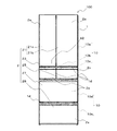
- FIG. 1 is a front view schematically showing an example of the appearance configuration of the refrigerator 100 according to the first embodiment.
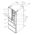
- FIG. 2 is a perspective view of the refrigerator 100 of FIG. 1 as viewed from above with the right door 21b of the refrigerator compartment door 21 opened.
- FIG. 3 is a perspective view schematically showing an example of the control device of the refrigerator 100 and the wiring of the control device according to the first embodiment.
- FIG. 4 is a perspective view of the refrigerator 100 of FIG. 1 as viewed from above with the left door 21a of the refrigerator compartment door 21 opened.
- each component of the refrigerator 100 in the following description for example, the positional relationship such as up / down, left / right, front / back, outside / inside, front / back, or vertical / horizontal, is installed in a state where the refrigerator 100 can be used in principle. It is the positional relationship when it is done.
- the dimensional relationship and shape of each component may differ from the actual ones.
- the same members or parts or members or parts having the same functions are designated by the same reference numerals or omitted.
- the refrigerator 100 has a box body 1 having an opening 1a on one side, and a plurality of doors 2 covering the opening 1a of the box body 1.
- the box body 1 and the door 2 form an outer shell of the refrigerator 100.
- the box body 1 is a heat-insulating housing capable of accommodating stored items such as food inside the box body 1. As shown in FIG. 2, the box body 1 has an opening 1a in the front direction. Further, the box body 1 includes an outer box 1b forming the outer shell of the refrigerator 100 and an inner box 1c forming the inner space of the refrigerator 100.
- the outer box 1b is made of a steel plate such as stainless steel.
- the inner box 1c is made of a synthetic resin such as plastic. Further, the space between the outer box 1b and the inner box 1c is filled with a heat insulating material such as a vacuum heat insulating material or urethane resin.
- the box body 1 has one or more heat insulating partition walls 1d.
- the partition wall 1d divides the internal space of the inner box 1c into one or more storage chambers 10 having different temperature zones.
- the inside of the partition wall 1d is filled with a vacuum heat insulating material, urethane resin, or the like so that heat conduction is not performed between the adjacent storage chambers 10 via the partition wall 1d.
- the storage room 10 can be formed as a refrigerating room 10a, an ice making room 10b, a switching room 10c, a freezing room 10d, and a vegetable room 10e.
- the refrigerating chamber 10a, the ice making chamber 10b, the switching chamber 10c, the freezing chamber 10d, and the vegetable compartment 10e are indicated by dotted leader lines.
- the switching chamber 10c can be used, for example, as a freezer having a different cold insulation temperature from the freezing chamber 10d.
- the door 2 opens or seals the internal space of the box 1.
- the door 2 is attached to the box body 1 so that the opening 1a can be opened and closed.
- the design surface 2a of the door 2 that is, the front surface and the peripheral surface is formed of glass or the like.
- the back surface 2b of the door 2 is made of a synthetic resin such as plastic.
- the space between the design surface 2a and the back surface 2b of the door 2 is filled with a heat insulating material having a heat insulating property such as a vacuum heat insulating material or urethane resin.
- the door 2 has a number of doors 2 corresponding to the storage chamber 10 of the refrigerator 100.
- the refrigerator 100 has five doors 2, that is, a refrigerator compartment door 21, an ice making chamber door 23, a switching chamber door 25, a freezer compartment door 27, and a vegetable compartment door. 29 is formed.
- the refrigerator compartment door 21 is attached to the box body 1 via a hinge 30.
- the hinge 30 connects the box body 1 and the refrigerator compartment door 21 and rotates the refrigerator compartment door 21.
- the refrigerator compartment door 21 is formed as a rotary double door having a left door 21a and a right door 21b.
- the left door 21a and the right door 21b are attached to the upper part of the box 1 via the left door hinge 30a and the right door hinge 30b, respectively.
- the left door 21a and the right door 21b are collectively referred to as a refrigerator compartment door 21, and the left door hinge 30a and the right door hinge 30b are collectively referred to as a hinge 30.
- the right door 21b is provided with a rotary partition 21c that extends in the vertical direction of the right door 21b and is rotatably attached to the left side of the back surface of the right door 21b.
- the rotary partition body 21c closes the gap formed between the left door 21a and the right door 21b when the refrigerating room door 21 is closed.
- the rotating partition 21c can suppress the leakage of cold air from the refrigerating chamber 10a and the inflow of outside air into the refrigerating chamber 10a.
- the refrigerator compartment door 21 may be rotatably attached to the right side of the back surface of the left door 21a. Further, the refrigerator compartment door 21 may be formed as a rotary single door, and when the refrigerator compartment door 21 is a rotary single door, the rotary partition 21c can be omitted.
- the ice making room door 23, the switching room door 25, the freezing room door 27, and the vegetable room door 29 are formed as, for example, a drawer type door.
- the pull-out door is provided with a pair of rods extending along the side wall of the inner box 1c on the back surface 2b of the door 2, and the rods are provided in the front-rear direction with respect to the pair of rails provided on the side wall of the inner box 1c. It is opened and closed by sliding it on.
- the refrigerator 100 is not limited to the above configuration, and any or all of the ice making chamber 10b, the switching chamber 10c, and the vegetable compartment 10e may be omitted depending on the form and use of the refrigerator 100, or the refrigerating chamber.
- One of 10a and the freezer 10d may be omitted.
- the freezing storage having only the freezing chamber 10d is also included in the refrigerator 100.
- the refrigerator 100 may have a plurality of storage chambers 10 for the same purpose depending on the form and use of the refrigerator 100.
- a circuit board 40 on which a power conversion circuit, a control circuit, and the like are mounted is housed between the outer box 1b and the inner box 1c on the upper back side of the refrigerator 100.
- the power conversion circuit includes, for example, an inverter circuit and a switching circuit.
- the control circuit is formed as, for example, a microcomputer provided with a central processing unit, a memory, and the like.
- the circuit board 40 controls the drive of the refrigerator 100, such as controlling the frequency of the compressor of the refrigerant circuit of the refrigerator 100 and controlling the rotation speed of the fan that sends cold air to the inside of the storage chamber 10.
- the circuit board 40 is connected to, for example, an AC200V or AC100V single-phase three-wire AC power supply.
- an operation panel 42 is arranged on the front surface of the refrigerator 100.
- the operation panel 42 is arranged, for example, on the left door 21a of the refrigerator compartment door 21.
- the operation panel 42 is formed as, for example, a capacitive touch panel.
- the operation panel 42 displays information on the state and operation of the refrigerator 100.
- a plurality of touch switches for setting the temperature of the refrigerator 100 and the like are displayed as icons.
- the operation panel 42 may be provided with a touch switch for lighting the operation panel 42 in order to suppress the power consumption of the operation panel 42.
- the operation panel 42 is wiredly connected to the circuit board 40 via, for example, a lead wire 48 formed of a copper wire or the like.
- a lead wire 48 formed of a copper wire or the like.
- the lead wire 48 connecting the operation panel 42 and the circuit board 40 is from the left door 21a of the refrigerating room door 21 to the left door hinge. It passes through the inside of 30a and is wired to the left edge portion and the trailing edge portion of the upper surface of the box body 1.
- the operation panel 42 may have a control circuit board such as a microcomputer on the back surface side of the operation panel 42, and the lead wire 48 may be connected to the control circuit board.
- the operation panel 42 is connected to the heater 45 provided in the rotary partition body 21c via the lead wire 48.
- the heater 45 maintains the front surface of the rotary partition 21c at a set temperature due to the heat generated when the heater 45 conducts conductivity, and dew condensation occurs on the front surface of the rotary partition 21c due to the temperature difference between the front surface of the rotary partition 21c and the outside air. Suppress the occurrence.
- a heat insulating material such as a vacuum heat insulating material is filled between the heater 45 and the back surface of the rotary partition 21c. By filling the space between the heater 45 and the back surface of the rotary partition 21c with a heat insulating material, it is possible to prevent the temperature inside the refrigerating chamber 10a from rising due to the heat of the heater 45.
- the operation panel 42 is connected to the humidity sensor 50 provided at the upper end of the left door 21a of the refrigerator compartment door 21 via the lead wire 48.
- the humidity sensor 50 is used to detect the humidity in the installation space of the refrigerator 100.
- the humidity sensor 50 includes, for example, a polymer resistance type or polymer capacity type semiconductor sensor using a moisture-sensitive polymer containing an additive such as an ammonium salt, or an aluminum oxide capacity type using porous aluminum oxide. A semiconductor sensor or the like is used. The specific structure of the humidity sensor 50 is not shown.
- the humidity information detected by the humidity sensor 50 is transmitted to the operation panel 42 or the circuit board 40 via the lead wire 48.
- a rotary partition is used depending on the humidity of the space where the refrigerator 100 is arranged. Condensation occurs on the front surface of the body 21c.
- the energization rate of the heater 45 is controlled by using the humidity information detected by the humidity sensor 50 in order to suppress the occurrence of dew condensation on the rotary partition body 21c. By controlling the energization rate of the heater 45, the temperature of the front surface of the rotary partition body 21c is adjusted, so that the occurrence of dew condensation on the front surface of the rotary partition body 21c can be suppressed.
- the humidity sensor 50 When the humidity sensor 50 is used to suppress the occurrence of dew condensation on the rotary partition 21c, the humidity sensor 50 is provided at the upper end, the lower end, or both of the rotary partition 21c to detect the humidity around the rotary partition 21c. Can be considered. However, since the rotary partition 21c is arranged on the back surface of the refrigerating chamber door 21, the information detected by the humidity sensor 50 is the influence of the cold air inside the refrigerating chamber 10a and the heat generated by the energization of the heater 45. Affected and affected. Therefore, the detection accuracy of the humidity sensor 50 is lowered due to the influence of the cold air inside the refrigerating chamber 10a and the influence of the heat generated by the energization of the heater 45.
- the humidity sensor 50 In order to suppress the influence of the cold air inside the refrigerator compartment 10a and the heat generated by the energization of the heater 45, it is conceivable to cover the humidity sensor 50 with a heat insulating material such as urethane resin. However, when the humidity sensor 50 is covered with the heat insulating material, the contact with the outside air in the humidity sensitive region of the humidity sensor 50 is hindered by the heat insulating material, and it may be difficult to maintain the detection accuracy of the humidity sensor 50.
- a heat insulating material such as urethane resin
- a refrigerator 100 in which a humidity sensor 50 is provided on the hinge 30 and the energization rate of the heater 45 provided on the rotary partition 21c is controlled by using the humidity information detected by the humidity sensor 50.
- the refrigerator 100 when the refrigerating chamber door 21 is opened, a part of the cold air discharged from the inside of the refrigerating chamber 10a flows in the direction of the hinge 30. Therefore, even in the refrigerator 100 in which the humidity sensor 50 is provided on the hinge 30, the cold air discharged from the inside of the refrigerating chamber 10a comes into contact with the humidity sensor 50 provided on the hinge 30, and the detection accuracy of the humidity sensor 50 is improved. May decrease.
- the humidity sensor 50 is provided on the hinge 30 as a method of suppressing a decrease in detection accuracy, there is a method in which the humidity sensor 50 is provided on both the left door hinge 30a and the right door hinge 30b.
- the humidity sensors 50 are provided on both the left door hinge 30a and the right door hinge 30b, the actual humidity estimation value is estimated based on the information detected by the plurality of humidity sensors 50.
- the control process for estimating the actual humidity estimate on the operation panel 42 or the circuit board 40 becomes complicated, it becomes difficult to reduce the manufacturing cost of the refrigerator 100.
- the detection accuracy of the humidity sensor 50 is that the humidity sensor 50 is arranged at a position where the influence of heat generated from the refrigerator 100 such as cold air and energization can be suppressed and does not hinder contact with the outside air. It is effective in maintaining the temperature and reducing the manufacturing cost of the refrigerator 100.
- FIG. 4 the flow of cold air in the state where the left door 21a of the refrigerator compartment door 21 is open is indicated by an arrow.
- the cold air from the refrigerating chamber 10a flows forward from the inside of the refrigerating chamber 10a.
- a part of the cold air from the refrigerating chamber 10a collides with the back surface of the left door 21a of the refrigerating chamber door 21 and flows upward along the back surface of the left door 21a of the refrigerating chamber door 21 to the left door 21a and the refrigerating chamber 10a. It flows upward from between.
- the humidity sensor 50 is housed in the upper end of the left door 21a of the refrigerating chamber door 21, the cold air flowing upward from between the left door 21a and the refrigerating chamber 10a comes into direct contact with the humidity sensor 50. Can be suppressed. Therefore, by accommodating the humidity sensor 50 in the upper end of the left door 21a of the refrigerator compartment door 21, it is possible to suppress an error in the measurement result of the outside air humidity.
- the humidity sensor 50 is arranged at a position away from the heater 45 provided in the rotary partition body 21c, it is possible to suppress an error in the measurement result of the outside air humidity due to the heat generated by the energization of the heater 45.
- the humidity sensor 50 in the upper end of the left door 21a of the refrigerator compartment door 21, it is possible to suppress an error in the measurement result of the outside air humidity, so that a control process for estimating the actual humidity estimation value is performed. Further, the arrangement of the humidity sensor 50 becomes unnecessary. Therefore, by accommodating the humidity sensor 50 in the upper end of the left door 21a of the refrigerator compartment door 21, the manufacturing cost of the refrigerator 100 can be reduced.
- FIG. 4 there is a refrigerator 100 in which a heat radiating pipe 35 is arranged on the upper part of the box body 1.
- the heat radiating pipe 35 forms a part of the refrigerant circuit of the refrigerator 100, and releases the thermal energy of the high-temperature and high-pressure vapor-phase refrigerant discharged from the compressor and passing through the heat radiating pipe 35 to the outside air through the surface of the box 1.
- the flow of heat energy from the heat radiating pipe 35 arranged in the upper part of the box 1 is indicated by an arrow.
- the humidity sensor 50 When the humidity sensor 50 is provided on the hinge 30, the heat energy from the heat radiating pipe 35 is transferred to the hinge 30, so that the detection accuracy of the humidity sensor 50 is lowered.
- a control process for estimating an estimated value of the actual humidity is performed, a coating of the humidity sensor 50 with a heat insulating material, and a further humidity sensor 50 are performed.
- the manufacturing cost of the refrigerator 100 will increase.
- the door 2 of the refrigerator 100 is filled with a heat insulating material, if the humidity sensor 50 is housed in the upper end of the left door 21a, the heat energy from the heat dissipation pipe 35 is transferred to the humidity sensor 50. Can be suppressed. Therefore, if the humidity sensor 50 is housed in the upper end of the left door 21a, the detection accuracy of the humidity sensor 50 can be maintained and the manufacturing cost of the refrigerator 100 can be reduced as compared with the case where the humidity sensor 50 is provided on the hinge 30. It becomes possible.
- the hinge 30 when the humidity sensor 50 is provided on the hinge 30, a space for mounting the humidity sensor 50 is required, so that the hinge 30 becomes large and the design of the refrigerator 100 is deteriorated. On the other hand, if the humidity sensor 50 is housed in the upper end of the left door 21a, the hinge 30 can be miniaturized, so that the design of the refrigerator 100 is improved.
- the user of the refrigerator 100 can touch the hinge 30 when the refrigerating room door 21 is open.
- the hinge 30 rotates.
- the hinge 30 will be disassembled in order to confirm the state. Therefore, when the humidity sensor 50 is provided on the hinge 30, the user of the refrigerator 100 has an opportunity to touch the humidity sensor 50 when disassembling the hinge 30.
- the detection performance of the humidity sensor 50 may deteriorate.
- the humidity sensor 50 is housed in the upper end of the left door 21a, the left door 21a needs to be disassembled in order for the user of the refrigerator 100 to touch the humidity sensor 50. Therefore, when the humidity sensor 50 is housed in the upper end of the left door 21a, the possibility that the user touches the humidity sensor 50 is reduced, so that the detection performance of the humidity sensor 50 can be maintained.
- the lead wire 48 is wired inside the box body 1 and the door 2, but the temperature distribution of the box body 1 and the door 2 is non-uniform.
- the heat dissipation pipe 35 is arranged in the box body 1. The temperature of the portion is high, but the temperature of the location near the storage chamber 10 of the box 1 and the door 2 is low. Therefore, in the lead wire 48 wired inside the box body 1 and the door 2, dew condensation may occur in the low temperature portion.
- a method of closing the hole through which the lead wire 48 passes with a water-expandable sealing material such as butyl rubber is adopted.
- a plurality of humidity sensors 50 are provided in the refrigerator 100, as the number of wires of the lead wires 48 increases, the amount of the sealing material used to close the holes through which the lead wires 48 pass increases, and the refrigerator 100 increases. Manufacturing costs may increase.
- the humidity sensor 50 when the humidity sensor 50 is housed in the upper end of the left door 21a, it is possible to suppress an error in the measurement result of the outside air humidity, so that it is not necessary to further arrange the humidity sensor 50 and use a sealing material. Therefore, by accommodating the humidity sensor 50 in the upper end of the left door 21a of the refrigerator compartment door 21, the manufacturing cost of the refrigerator 100 can be reduced.
- the humidity sensor 50 can be wirelessly connected to the operation panel 42.
- the degree of freedom of arrangement is increased, so that not only the left door 21a of the refrigerating room door 21 but also the right door 21b of the refrigerating room door 21, the ice making room door 23, the switching room door 25, It can be arranged at the upper end of any of the doors 2 of the freezing room door 27 and the vegetable room door 29. Further, not only between the humidity sensor 50 and the operation panel 42, but also between the operation panel 42 and the circuit board 40, and between the operation panel 42 and the heater 45 can be wirelessly connected.
- the humidity sensor 50 includes not only the double-door refrigerating room door 21, but also the single-sided refrigerating room door 21, the ice making room door 23, the switching room door 25, the freezing room door 27, and the vegetable room door 29, depending on the application. It can be arranged at the upper end of any of the doors 2 at the upper end of the door 2.
- the humidity sensor 50 is provided at the upper end of the vegetable compartment door 29 when the dew condensation on the partition wall 1d between the freezer compartment door 27 and the vegetable compartment door 29 is suppressed by using a heat transfer device. be able to.
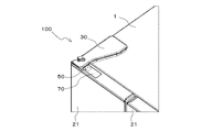
- FIG. 5 is an enlarged perspective view of the upper left surface showing an example of the refrigerator 100 according to the second embodiment.
- FIG. 6 is an exploded perspective view showing a state in which the hinge cover 34 and the lid 70 are detached from each other in the refrigerator 100 of FIG.
- the display of the position of the humidity sensor 50 or the humidity sensor 50 is omitted.
- a hinge 30 is attached to the upper part of the refrigerator compartment door 21 of the refrigerator 100.
- the hinge 30 has a hinge main body 32 and a hinge cover 34 that covers the hinge main body 32.
- the hinge body 32 is made of a sheet metal such as a stainless steel rope.
- a shaft hole 32a is formed in the hinge main body 32, and the shaft hole 32a of the hinge main body 32 is attached to a rotating shaft 22 formed in the upper part of the refrigerating chamber door 21.
- a plurality of fastening holes 32b are formed in the hinge main body 32.
- the hinge main body 32 is connected to the box body 1 by a fastening member such as a screw via a plurality of fastening holes 32b.
- first mounting hole 32c1 and a second mounting hole 32c2 for mounting the hinge cover 34 are provided on the peripheral edge of the hinge main body 32.
- the first mounting hole 32c1 is formed between the first mounting hole 32c1 and the upper surface of the box body 1 and opens in the left side direction of the box body 1.
- the second mounting hole 32c2 is formed between the second mounting hole 32c2 and the upper surface of the box body 1 and opens toward the right side of the box body 1.
- the hinge cover 34 is molded by, for example, molding a thermoplastic resin such as plastic.
- the hinge cover 34 has an upper wall 34a that covers the upper surface of the hinge body 32 and a side wall 34b that covers the peripheral edge of the hinge body 32.
- the side wall 34b of the hinge cover 34 is provided with a first protrusion 34c1 protruding inward of the hinge cover 34 along the upper wall 34a of the hinge cover 34.
- the upper wall 34a of the hinge cover 34 is provided with a protrusion support wall 34d extending in a direction away from the upper wall 34a, and the tip 34d1 of the protrusion support wall 34d is provided with a second protrusion 34c2.
- the second protrusion 34c2 projects from the tip 34d1 of the protrusion support wall 34d in the direction of the side wall 34b where the first protrusion 34c1 is provided.
- the first protrusion 34c1 of the hinge cover 34 is detachably housed in the first mounting hole 32c1, and the second protrusion 34c2 of the hinge cover 34 is accommodated. It is detachably housed in the second mounting hole 32c2. As a result, the hinge cover 34 is detachably attached to the hinge body 32.
- the hinge 30 can be attached to the upper part of the refrigerator compartment door 21 so that the upper surface of the upper wall 34a of the hinge cover 34 is in the same position as the upper surface of the box 1 in the horizontal direction. Thereby, the design of the refrigerator 100 can be improved.
- a recess 60 is formed at the upper end of the refrigerator compartment door 21.
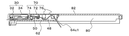
- a humidity sensor 50 is housed in the recess 60.
- the recess 60 can be integrally formed with the refrigerating chamber door 21, for example, by molding the refrigerating chamber door 21 with a mold.
- the recess 60 extends from the bottom wall 62 formed inside the refrigerating room door 21 and the peripheral edge portion 62a of the bottom wall 62 toward the upper surface side of the refrigerating room door 21 at the upper end of the refrigerating room door 21, for example. It is partitioned by a U-shaped first side wall 64.
- the first side wall 64 is a first wall 64a arranged on the back surface side of the refrigerating room door 21, and a second wall 64b arranged on the front surface side of the refrigerating room door 21 and arranged apart from the first wall 64a. And have. Further, the first side wall 64 is connected to the first wall 64a and the second wall 64b, and has a third wall 64c arranged on the right side side of the refrigerator compartment door 21.
- the first wall 64a, the second wall 64b, and the third wall 64c of the first side wall 64 may be formed in a staircase shape as shown in FIG. 5, or as shown in FIG. 11 described later. It may be formed in a flat shape. Further, only a part of the first wall 64a, the second wall 64b, and the third wall 64c of the first side wall 64 may be formed in a staircase shape, and the other part may be formed in a flat shape.
- first wall 64a of the first side wall 64 is provided with a hole 66 opened toward the inside of the recess 60.
- the second wall 64b of the first side wall 64 is also provided with a hole 66 opened toward the inside of the recess 60.
- the position of the hole 66 in the second wall 64b of the first side wall 64 is indicated by a dotted leader line.
- a lead wire 48 connected to the humidity sensor 50 is drawn into the recess 60, and the tip of the lead wire 48 is made of plastic resin as a terminal for connecting the lead wire 48 and the humidity sensor 50.
- a connector 48a is provided.
- the refrigerator compartment door 21 is provided with a lid 70 that covers the recess 60.
- the humidity sensor 50 is attached to the lid 70 and can be accommodated in the recess 60. By attaching the humidity sensor 50 to the lid 70, even if the bottom wall 62 of the recess 60 is dewed, it is possible to suppress the adhesion of moisture to the humidity sensor 50, so that the measurement result of the outside air humidity due to the adhesion of moisture can be suppressed. Error can be suppressed.
- FIG. 7 is a perspective view showing an example of the lid 70 according to the refrigerator 100 of the second embodiment.
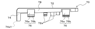
- FIG. 8 is a side view of the lid 70 of FIG. 7 as viewed from the front arrangement side.
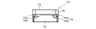
- FIG. 9 is a back view of the lid 70 of FIG. 7 as viewed from the back side of the first panel 72.
- FIG. 10 is a side view of the lid 70 of FIG. 7 as viewed from the back surface side of the second panel 74.
- the display of the position of the humidity sensor 50 or the humidity sensor 50 is omitted.
- the lid 70 is molded by, for example, molding a thermoplastic resin such as plastic.
- the lid 70 has a first panel 72 that forms a part of the upper surface of the refrigerator compartment door 21, and a second panel 74 that is connected to the first panel 72.
- the first panel 72 and the second panel 74 can be connected by, for example, a curved panel.
- the first panel 72 is attached to the upper end of the first side wall 64 of the recess 60.
- the second panel 74 is attached at a position facing the third wall 64c of the first side wall 64.
- the second panel 74 is formed so as to cover the opening between the first panel 72, the first side wall 64, and the bottom wall 62.
- the lid body 70 has a sensor support leg 72a extending in a direction away from the first panel 72.
- the sensor support legs 72a are provided on the back surface of the first panel 72.
- the sensor support legs 72a are arranged so as to support the corners and peripheral edges of the printed circuit board of the humidity sensor 50, for example.
- the sensor support leg 72a may be provided with, for example, a gripping member that supports the sensor support leg 72a by sandwiching the corner and the peripheral edge of the printed circuit board of the humidity sensor 50 at the tip of the sensor support leg 72a.
- the humidity sensor 50 can be arranged on the back surface of the first panel 72 and can be accommodated at a position separated from the bottom wall 62 of the recess 60. Therefore, even when the bottom wall 62 of the recess 60 is dewed, it is possible to suppress the adhesion of moisture to the humidity sensor 50, so that the error in the measurement result of the outside air humidity due to the adhesion of the moisture can be further suppressed.
- the lid body 70 has a hook 76 that is connected to the first panel 72 and extends in a direction away from the first panel 72.
- a plurality of hooks 76 are formed in an L shape and are provided on the back surface of the first panel 72.
- the hook 76 has a connecting leg 76a extending in a direction away from the back surface of the first panel 72, and a claw 76b provided at the tip of the connecting leg 76a.
- the claw 76b projects in a direction away from the center line C passing through the center of the first panel 72 and the center of the second panel 74.
- the claw 76b provided at the tip of the connecting leg 76a is inserted into the hole 66 provided in the first side wall 64.
- the hook 76 is moored to the first side wall 64 by inserting the claw 76b provided at the tip of the connecting leg 76a into the hole 66 of the first side wall 64. Therefore, by providing the hook 76 in the lid 70 and providing the hole 66 for fastening the hook 76 in the first side wall 64, the lid 70 can be detachably attached to the recess 60.
- the position and number of holes 66 provided in the first side wall 64 are not particularly limited, but at least one is provided in each of the first wall 64a and the second wall 64b of the first side wall 64, and the first wall 64a is provided. It is preferable that the hook 76 can be moored to each of the second wall 64b and the second wall 64b. By mooring the hook 76 to each of the first wall 64a and the second wall 64b, the lid 70 slides in the direction of the second panel 74 and is detached while the lid 70 is attached to the recess 60. The possibility of doing so can be reduced.
- the lid 70 can be provided with a guide panel 78 that is connected to the first panel 72 and extends in a direction away from the first panel 72.
- the guide panel 78 can be formed so as to be connected to the first panel 72 and the second panel 74 and to have a U shape when viewed from the back surface side of the first panel 72, for example.
- the lid 70 is recessed in a state where the guide panel 78 is in contact with all of the first wall 64a, the second wall 64b, and the third wall 64c of the first side wall 64. It can be attached to 60. Therefore, the positioning of the lid 70 when the lid 70 is attached to the recess 60 becomes easy.
- the guide panel 78 may be formed as a plurality of independent guide panels 78 in contact with each of the first wall 64a, the second wall 64b, and the third wall 64c, or the first wall 64a and the second wall 64a. It may be formed so as to come into contact with only a part of 64b and the third wall 64c. Further, when the first wall 64a, the second wall 64b, and the third wall 64c are formed in a flat shape, instead of the guide panel 78, the connecting leg 76a of the hook 76 is used as the first wall 64a and the second wall 64b.
- the guide panel 78 can be omitted from the lid 70 by contacting the lid 70.
- the recess 60 is integrally formed with the refrigerating chamber door 21
- the recess 60 can be formed as a separate member housed in the upper end portion of the refrigerating chamber door 21. ..
- the refrigerator 100 in which the recess 60 is formed in the sensor storage case 80 housed in the upper end of the refrigerator compartment door 21 will be described with reference to FIGS. 11 and 12.
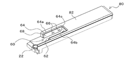
- FIG. 11 is a perspective view showing an example of the sensor accommodating case 80 according to the refrigerator 100 of the second embodiment.
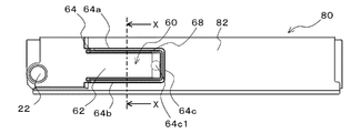
- FIG. 12 is a top view of the sensor accommodating case 80 of FIG.
- the display of the position of the humidity sensor 50 or the humidity sensor 50 is omitted.
- the sensor accommodating case 80 forms a part of the upper surface of the refrigerator compartment door 21 and functions as a cap that covers the upper end portion of the refrigerator compartment door 21.
- the sensor housing case 80 is molded by, for example, molding a thermoplastic resin such as plastic.
- the sensor accommodating case 80 has a shell 82 that forms the upper end of the refrigerator compartment door 21, and the recess 60 is formed in the shell 82.
- a lead-in hole 64c1 for drawing the lead wire 48 into the recess 60 is formed in the third wall 64c of the first side wall 64 of the recess 60.
- the first wall 64a, the second wall 64b, and the third wall 64c of the first side wall 64 have a flat shape. Since the structure of the other recesses 60 is the same as the structure of the recesses 60 already described, the description thereof will be omitted.
- the sensor accommodating case 80 is formed with a rotating shaft 22 to which the shaft hole 32a of the hinge main body 32 is attached.
- the recess 60 in the sensor accommodating case 80 it is possible to perform maintenance and inspection such as replacement of the humidity sensor 50 with the lid 70 and the sensor accommodating case 80 detached from each other. Can be improved. Further, by providing the recess 60 in the sensor accommodating case 80, it becomes easy to remove dust or water droplets adhering to the bottom wall 62 of the recess 60.
- FIG. 13 is a perspective view showing an example of the sensor accommodating case 80 according to the refrigerator 100 of the third embodiment.
- FIG. 14 is a top view of the sensor accommodating case 80 of FIG.
- FIG. 15 is a schematic view showing an XX cross section of FIG.
- the display of the position of the humidity sensor 50 or the humidity sensor 50 is omitted.
- the recess 60 of the sensor accommodating case 80 of the third embodiment is provided with a second side wall 68 which is arranged at a distance from the first side wall 64 and extends from the bottom wall 62 to the upper surface side of the refrigerator door 21.
- the second side wall 68 is housed inside the recess 60 and is arranged at a position surrounded by the bottom wall 62 and the first side wall 64.
- a hole 66 is provided in the second side wall 68.
- the recess 60 may be provided with a connecting wall 68a for connecting the gap between the first side wall 64 and the second side wall 68.
- the other configurations of the refrigerator 100 are the same as those described in the second embodiment, and thus the description thereof will be omitted.
- the guide panel 78 of the lid 70 can be arranged in the gap between the first side wall 64 and the second side wall 68 to position the lid 70. Therefore, the efficiency of the work of attaching the lid 70 to the recess 60 can be improved.
- the tip of the second side wall 68 of the recess 60 can be brought into contact with the back surface of the first panel 72 of the lid 70, so that the first of the lid 70 can be brought into contact with the back surface.
- the panel 72 can be supported in the recess 60 by the second side wall 68. Therefore, by providing the second side wall 68 in the recess 60, it is possible to prevent the lid 70 from entering the inside of the recess 60 due to the application of an external force or the like and preventing the humidity sensor 50 from coming into contact with the bottom wall 62 of the recess 60.
- the contact of the humidity sensor 50 with the bottom wall 62 can be suppressed, the failure of the humidity sensor 50 due to a short circuit or the like can be suppressed. Further, since the contact of the humidity sensor 50 with the bottom wall 62 can be suppressed, an error in the measurement result of the outside air humidity can be suppressed, and the reliability of the measurement result can be improved.
- the water flows into the gap between the first side wall 64 and the second side wall 68, and the water adheres to the humidity sensor 50. It can be suppressed. Therefore, by providing the second side wall 68 in the recess 60, it is possible to suppress the adhesion of water to the humidity sensor 50, so that the failure of the humidity sensor 50 due to a short circuit or the like can be suppressed. Further, since the adhesion of water to the humidity sensor 50 can be suppressed, an error in the measurement result of the outside air humidity can be suppressed, and the reliability of the measurement result can be improved.
- the tip of the second side wall 68 of the recess 60 into contact with the back surface of the first panel 72 of the lid 70 the upper surface of the shell 82 of the sensor accommodating case 80 and the upper surface of the first panel 72 of the lid 70 are brought into contact with each other. Can be placed on the same plane. Therefore, by providing the second side wall 68 in the recess 60, the design of the refrigerator compartment door 21 can be improved.
- the above-mentioned effect can be obtained other than bringing the tip of the second side wall 68 of the recess 60 into contact with the back surface of the first panel 72 of the lid 70.
- the same can be obtained even when the tip of the guide panel 78 of the lid 70 is brought into contact with the connecting wall 68a connecting the gaps between the first side wall 64 and the second side wall 68.
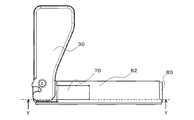
- FIG. 16 is a top view showing an example of the arrangement of the hinge 30, the lid 70, and the sensor accommodating case 80 according to the refrigerator 100 of the fourth embodiment.
- FIG. 17 is a schematic view showing a YY cross section of FIG. In FIG. 17, the inclination direction of the bottom wall 62 of the recess 60 is indicated by a solid arrow. Further, in FIGS. 16 and 17, the display of the position of the humidity sensor 50 or the humidity sensor 50 is omitted.
- the width between the first panel 72 of the lid 70 and the bottom wall 62 of the recess 60 increases as the distance from the third wall 64c of the first side wall 64 of the recess 60 increases.
- the bottom wall 62 of the recess 60 is inclined downward toward the second panel 74 of the lid 70.
- the connecting wall 68a of the recess 60 described in the third embodiment can also be inclined downward toward the second panel 74 to promote the discharge of flooded water, so that the same effect as described above can be obtained. .. Further, the configuration of the fourth embodiment can be adopted even when the recess 60 is integrally formed with the refrigerating chamber door 21, and the same effect can be obtained by adopting the recess 60.
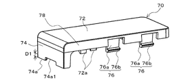
- FIG. 18 is a perspective view showing an example of the lid 70 according to the refrigerator 100 of the fifth embodiment.
- FIG. 19 is a top view showing an example of the arrangement of the hinge 30, the lid 70, and the sensor accommodating case 80 according to the refrigerator 100 of the fifth embodiment.
- FIG. 20 is a schematic view showing a ZZ cross section of FIG. Note that in FIGS. 18 and 19, the display of the position of the humidity sensor 50 or the humidity sensor 50 is omitted. Further, in FIG. 20, the flow of outside air is indicated by a solid arrow.
- a notch hole 74a1 is formed at the end 74a of the second panel 74 of the lid 70, which is located on the side of the bottom wall 62 of the recess 60. Further, the length D1 of the notch hole 74a1 in the direction away from the end 74a of the second panel 74 is 3.5 mm or less.
- the hinge 30 is arranged so as to face the second panel 74. Further, by arranging the upper surface of the hinge cover 34 of the hinge 30 on the same plane as the upper surface of the first panel 72 of the lid 70 and the upper surface of the shell 82 of the sensor accommodating case 80, the design of the upper surface of the refrigerator 100 can be improved. Can be improved.
- the other configurations of the refrigerator 100 are the same as those described in the second embodiment, and thus the description thereof will be omitted.
- the notch hole 74a1 in the lid 70 By providing the notch hole 74a1 in the lid 70, the outside air that has passed between the hinge 30 and the refrigerator door 21 can be taken into the recess 60. Therefore, by providing the notch hole 74a1 in the lid 70, the accuracy of the measurement result of the outside air humidity can be improved, so that the reliability of the measurement result can be improved.
- the formation position of the notch hole 74a1 to the end 74a of the second panel 74 of the lid 70 it is possible to suppress the intrusion of water from the notch hole 74a1. Therefore, by setting the formation position of the notch hole 74a1 to the end 74a of the second panel 74 of the lid 70, it is possible to suppress the adhesion of water to the humidity sensor 50, and thus it is possible to suppress the failure of the humidity sensor 50 due to a short circuit or the like. .. Further, since the adhesion of water to the humidity sensor 50 can be suppressed, an error in the measurement result of the outside air humidity can be suppressed, and the reliability of the measurement result can be improved.
- the length D1 of the notch hole 74a1 is set to 3.5 mm or less, it is possible to suppress the user's finger from entering the recess 60, so that the failure of the humidity sensor 50 can be suppressed.
- FIG. 21 is a side view of the lid 70 according to the refrigerator 100 of the sixth embodiment as viewed from the front arrangement side.
- FIG. 22 is a back view of the lid 70 according to the refrigerator 100 of the sixth embodiment as viewed from the back side of the first panel 72.
- the display of the position of the humidity sensor 50 or the humidity sensor 50 is omitted.
- the sensor support leg 72a in the first panel 72 of the lid 70, has a distance D2 between the notch hole 74a1 of the second panel 74 and the humidity sensor 50 supported by the sensor support leg 72a. It is formed so as to be 20 mm or more.
- the other configurations of the lid 70 are the same as those described in the second and fifth embodiments, and thus the description thereof will be omitted.
- the distance D2 between the notch hole 74a1 and the humidity sensor 50 By setting the distance D2 between the notch hole 74a1 and the humidity sensor 50 to 20 mm or more, it is possible to prevent dust and the like entering from the notch hole 74a1 from adhering to the humidity sensor 50 while ensuring the detection performance of the outside air. Therefore, by setting the distance D2 between the notch hole 74a1 and the humidity sensor 50 to 20 mm or more, it is possible to suppress an error in the measurement result of the outside air humidity, and thus the reliability of the measurement result can be improved. Further, by setting the distance D2 between the notch hole 74a1 and the humidity sensor 50 to 20 mm or more, the influence of static electricity generated in the vicinity of the notch hole 74a1 can be reduced, so that the humidity sensor 50 can be prevented from failing.
- Embodiment 7 The configuration of the sensor accommodating case 80 according to the refrigerator 100 of the seventh embodiment will be described with reference to FIGS. 23 and 24.
- FIG. 23 is a top view schematically showing an example of the configuration of the refrigerator 100 according to the seventh embodiment.
- FIG. 24 is a plan view of the sensor accommodating case 80 according to the refrigerator 100 of the seventh embodiment as viewed from the back surface side.
- the flow of heat energy from the heat radiating pipe 35 is indicated by an arrow.
- FIGS. 23 and 24 the display of the position of the humidity sensor 50 or the humidity sensor 50 is omitted.
- the first wall 64a which is the first side wall 64 on the back surface side of the refrigerator compartment door 21, is formed so as to include the heat insulating body 90.
- the heat insulating body 90 is formed of a heat insulating material having a higher heat insulating property than the urethane resin, for example, a vacuum heat insulating material.
- the heat insulating body 90 is arranged in the gap between the back surface of the refrigerating room door 21 and the first wall 64a.
- the other configurations of the refrigerator 100 are the same as those described in the second embodiment, and thus the description thereof will be omitted.
- the first wall 64a of the first side wall 64 so as to include the heat insulating body 90, heat is transferred from the recess 60 to the cold air flowing upward from between the refrigerating chamber door 21 and the refrigerating chamber 10a. Also, heat transfer from the front surface of the box 1 to the recess 60 by the heat radiating pipe 35 can be suppressed. Therefore, by forming the first wall 64a of the first side wall 64 so as to include the heat insulating body 90, it is caused by the influence of the cold air inside the refrigerating chamber 10a and the influence of the heat transferred from the heat radiating pipe 35. It is possible to suppress the occurrence of an error in the measurement result of the outside air humidity. Therefore, by forming the first wall 64a of the first side wall 64 so as to include the heat insulating body 90, it is possible to suppress an error in the measurement result of the outside air humidity and improve the reliability of the measurement result.
- the configuration of the seventh embodiment can be adopted even when the recess 60 is integrally formed with the refrigerating chamber door 21.
- the first wall 64a of the first side wall 64 is formed of a heat insulating material having a higher heat insulating property than the urethane resin, for example, a vacuum heat insulating material, the same effect can be obtained.
Landscapes
- Engineering & Computer Science (AREA)
- Chemical & Material Sciences (AREA)
- Combustion & Propulsion (AREA)
- Physics & Mathematics (AREA)
- Mechanical Engineering (AREA)
- Thermal Sciences (AREA)
- General Engineering & Computer Science (AREA)
- Devices That Are Associated With Refrigeration Equipment (AREA)
Priority Applications (2)
| Application Number | Priority Date | Filing Date | Title |
|---|---|---|---|
| JP2022508704A JP7325609B2 (ja) | 2020-03-18 | 2020-03-18 | 冷蔵庫 |
| PCT/JP2020/011968 WO2021186613A1 (ja) | 2020-03-18 | 2020-03-18 | 冷蔵庫 |
Applications Claiming Priority (1)
| Application Number | Priority Date | Filing Date | Title |
|---|---|---|---|
| PCT/JP2020/011968 WO2021186613A1 (ja) | 2020-03-18 | 2020-03-18 | 冷蔵庫 |
Publications (1)
| Publication Number | Publication Date |
|---|---|
| WO2021186613A1 true WO2021186613A1 (ja) | 2021-09-23 |
Family
ID=77771005
Family Applications (1)
| Application Number | Title | Priority Date | Filing Date |
|---|---|---|---|
| PCT/JP2020/011968 Ceased WO2021186613A1 (ja) | 2020-03-18 | 2020-03-18 | 冷蔵庫 |
Country Status (2)
| Country | Link |
|---|---|
| JP (1) | JP7325609B2 (cg-RX-API-DMAC7.html) |
| WO (1) | WO2021186613A1 (cg-RX-API-DMAC7.html) |
Citations (10)
| Publication number | Priority date | Publication date | Assignee | Title |
|---|---|---|---|---|
| JPH10339555A (ja) * | 1997-06-09 | 1998-12-22 | Matsushita Refrig Co Ltd | 冷蔵庫 |
| JP2003207258A (ja) * | 2002-01-16 | 2003-07-25 | Toshiba Corp | 冷蔵庫 |
| JP2004116788A (ja) * | 2002-09-20 | 2004-04-15 | Toshiba Corp | 冷蔵庫扉 |
| JP2007278585A (ja) * | 2006-04-06 | 2007-10-25 | Matsushita Electric Ind Co Ltd | 冷蔵庫扉 |
| KR20120084093A (ko) * | 2011-01-19 | 2012-07-27 | 엘지전자 주식회사 | 냉장고 및 그 제어방법 |
| JP2013072595A (ja) * | 2011-09-28 | 2013-04-22 | Hitachi Appliances Inc | 冷蔵庫および冷凍庫 |
| JP2018112398A (ja) * | 2018-04-11 | 2018-07-19 | 東芝ライフスタイル株式会社 | 冷蔵庫 |
| WO2019016958A1 (ja) * | 2017-07-21 | 2019-01-24 | 三菱電機株式会社 | 冷蔵庫 |
| JP2019152354A (ja) * | 2018-03-01 | 2019-09-12 | 東芝ライフスタイル株式会社 | 冷蔵庫 |
| JP2019200043A (ja) * | 2019-07-26 | 2019-11-21 | シャープ株式会社 | 冷蔵庫 |
Family Cites Families (1)
| Publication number | Priority date | Publication date | Assignee | Title |
|---|---|---|---|---|
| KR20090047811A (ko) | 2007-11-08 | 2009-05-13 | 엘지전자 주식회사 | 냉장고 |
-
2020
- 2020-03-18 JP JP2022508704A patent/JP7325609B2/ja active Active
- 2020-03-18 WO PCT/JP2020/011968 patent/WO2021186613A1/ja not_active Ceased
Patent Citations (10)
| Publication number | Priority date | Publication date | Assignee | Title |
|---|---|---|---|---|
| JPH10339555A (ja) * | 1997-06-09 | 1998-12-22 | Matsushita Refrig Co Ltd | 冷蔵庫 |
| JP2003207258A (ja) * | 2002-01-16 | 2003-07-25 | Toshiba Corp | 冷蔵庫 |
| JP2004116788A (ja) * | 2002-09-20 | 2004-04-15 | Toshiba Corp | 冷蔵庫扉 |
| JP2007278585A (ja) * | 2006-04-06 | 2007-10-25 | Matsushita Electric Ind Co Ltd | 冷蔵庫扉 |
| KR20120084093A (ko) * | 2011-01-19 | 2012-07-27 | 엘지전자 주식회사 | 냉장고 및 그 제어방법 |
| JP2013072595A (ja) * | 2011-09-28 | 2013-04-22 | Hitachi Appliances Inc | 冷蔵庫および冷凍庫 |
| WO2019016958A1 (ja) * | 2017-07-21 | 2019-01-24 | 三菱電機株式会社 | 冷蔵庫 |
| JP2019152354A (ja) * | 2018-03-01 | 2019-09-12 | 東芝ライフスタイル株式会社 | 冷蔵庫 |
| JP2018112398A (ja) * | 2018-04-11 | 2018-07-19 | 東芝ライフスタイル株式会社 | 冷蔵庫 |
| JP2019200043A (ja) * | 2019-07-26 | 2019-11-21 | シャープ株式会社 | 冷蔵庫 |
Also Published As
| Publication number | Publication date |
|---|---|
| JPWO2021186613A1 (cg-RX-API-DMAC7.html) | 2021-09-23 |
| JP7325609B2 (ja) | 2023-08-14 |
Similar Documents
| Publication | Publication Date | Title |
|---|---|---|
| KR102186861B1 (ko) | 냉장고 | |
| JP5402779B2 (ja) | 冷蔵庫 | |
| CN107923690A (zh) | 冷藏库 | |
| US8434317B2 (en) | Anti-sweat heater demand supply module using temperature and humidity control | |
| US9970704B2 (en) | Structure of a refrigerator body | |
| US11060788B2 (en) | Household refrigeration appliance with a door stop bar having a heating line thermally coupled thereto by a heat conducting transmission medium | |
| JP2005069596A (ja) | 冷蔵庫 | |
| JP7008822B2 (ja) | 冷蔵庫およびその製造方法 | |
| JP2015215153A (ja) | 冷蔵庫 | |
| JP2005299936A (ja) | 冷蔵庫 | |
| WO2021186613A1 (ja) | 冷蔵庫 | |
| JP7561596B2 (ja) | 冷蔵庫 | |
| CN113825965B (zh) | 冰箱 | |
| JP2008107045A (ja) | 冷蔵庫 | |
| JP5919582B2 (ja) | 冷蔵庫 | |
| WO2018003548A1 (ja) | 冷蔵庫 | |
| JP2018128207A (ja) | 冷蔵庫 | |
| JP7133605B2 (ja) | 冷蔵庫 | |
| WO2020170310A1 (ja) | 冷蔵庫 | |
| JP2017187233A (ja) | 冷蔵庫 | |
| JP7275377B2 (ja) | 冷蔵庫 | |
| CN116761969B (zh) | 冰箱 | |
| JP4949138B2 (ja) | 冷蔵庫 | |
| WO2018003549A1 (ja) | 冷蔵庫 | |
| WO2019171533A1 (ja) | 冷蔵庫 |
Legal Events
| Date | Code | Title | Description |
|---|---|---|---|
| 121 | Ep: the epo has been informed by wipo that ep was designated in this application |
Ref document number: 20925018 Country of ref document: EP Kind code of ref document: A1 |
|
| ENP | Entry into the national phase |
Ref document number: 2022508704 Country of ref document: JP Kind code of ref document: A |
|
| NENP | Non-entry into the national phase |
Ref country code: DE |
|
| 122 | Ep: pct application non-entry in european phase |
Ref document number: 20925018 Country of ref document: EP Kind code of ref document: A1 |