WO2021182632A1 - マイクロ液滴・気泡生成デバイス - Google Patents
マイクロ液滴・気泡生成デバイス Download PDFInfo
- Publication number
- WO2021182632A1 WO2021182632A1 PCT/JP2021/010205 JP2021010205W WO2021182632A1 WO 2021182632 A1 WO2021182632 A1 WO 2021182632A1 JP 2021010205 W JP2021010205 W JP 2021010205W WO 2021182632 A1 WO2021182632 A1 WO 2021182632A1
- Authority
- WO
- WIPO (PCT)
- Prior art keywords
- dispersed phase
- microchannels
- continuous phase
- slit
- slits
- Prior art date
- Legal status (The legal status is an assumption and is not a legal conclusion. Google has not performed a legal analysis and makes no representation as to the accuracy of the status listed.)
- Ceased
Links
Images





Classifications
-
- B—PERFORMING OPERATIONS; TRANSPORTING
- B01—PHYSICAL OR CHEMICAL PROCESSES OR APPARATUS IN GENERAL
- B01F—MIXING, e.g. DISSOLVING, EMULSIFYING OR DISPERSING
- B01F33/00—Other mixers; Mixing plants; Combinations of mixers
- B01F33/30—Micromixers
- B01F33/301—Micromixers using specific means for arranging the streams to be mixed, e.g. channel geometries or dispositions
- B01F33/3012—Interdigital streams, e.g. lamellae
-
- B—PERFORMING OPERATIONS; TRANSPORTING
- B01—PHYSICAL OR CHEMICAL PROCESSES OR APPARATUS IN GENERAL
- B01F—MIXING, e.g. DISSOLVING, EMULSIFYING OR DISPERSING
- B01F23/00—Mixing according to the phases to be mixed, e.g. dispersing or emulsifying
- B01F23/40—Mixing liquids with liquids; Emulsifying
- B01F23/41—Emulsifying
-
- B—PERFORMING OPERATIONS; TRANSPORTING
- B01—PHYSICAL OR CHEMICAL PROCESSES OR APPARATUS IN GENERAL
- B01F—MIXING, e.g. DISSOLVING, EMULSIFYING OR DISPERSING
- B01F23/00—Mixing according to the phases to be mixed, e.g. dispersing or emulsifying
- B01F23/20—Mixing gases with liquids
- B01F23/23—Mixing gases with liquids by introducing gases into liquid media, e.g. for producing aerated liquids
- B01F23/232—Mixing gases with liquids by introducing gases into liquid media, e.g. for producing aerated liquids using flow-mixing means for introducing the gases, e.g. baffles
- B01F23/2323—Mixing gases with liquids by introducing gases into liquid media, e.g. for producing aerated liquids using flow-mixing means for introducing the gases, e.g. baffles by circulating the flow in guiding constructions or conduits
-
- B—PERFORMING OPERATIONS; TRANSPORTING
- B01—PHYSICAL OR CHEMICAL PROCESSES OR APPARATUS IN GENERAL
- B01F—MIXING, e.g. DISSOLVING, EMULSIFYING OR DISPERSING
- B01F23/00—Mixing according to the phases to be mixed, e.g. dispersing or emulsifying
- B01F23/40—Mixing liquids with liquids; Emulsifying
- B01F23/41—Emulsifying
- B01F23/414—Emulsifying characterised by the internal structure of the emulsion
- B01F23/4143—Microemulsions
-
- B—PERFORMING OPERATIONS; TRANSPORTING
- B01—PHYSICAL OR CHEMICAL PROCESSES OR APPARATUS IN GENERAL
- B01F—MIXING, e.g. DISSOLVING, EMULSIFYING OR DISPERSING
- B01F25/00—Flow mixers; Mixers for falling materials, e.g. solid particles
- B01F25/30—Injector mixers
- B01F25/31—Injector mixers in conduits or tubes through which the main component flows
- B01F25/314—Injector mixers in conduits or tubes through which the main component flows wherein additional components are introduced at the circumference of the conduit
- B01F25/3141—Injector mixers in conduits or tubes through which the main component flows wherein additional components are introduced at the circumference of the conduit with additional mixing means other than injector mixers
-
- B—PERFORMING OPERATIONS; TRANSPORTING
- B01—PHYSICAL OR CHEMICAL PROCESSES OR APPARATUS IN GENERAL
- B01F—MIXING, e.g. DISSOLVING, EMULSIFYING OR DISPERSING
- B01F25/00—Flow mixers; Mixers for falling materials, e.g. solid particles
- B01F25/30—Injector mixers
- B01F25/31—Injector mixers in conduits or tubes through which the main component flows
- B01F25/314—Injector mixers in conduits or tubes through which the main component flows wherein additional components are introduced at the circumference of the conduit
- B01F25/3143—Injector mixers in conduits or tubes through which the main component flows wherein additional components are introduced at the circumference of the conduit characterised by the specific design of the injector
- B01F25/31432—Injector mixers in conduits or tubes through which the main component flows wherein additional components are introduced at the circumference of the conduit characterised by the specific design of the injector being a slit extending in the circumferential direction only
-
- B—PERFORMING OPERATIONS; TRANSPORTING
- B01—PHYSICAL OR CHEMICAL PROCESSES OR APPARATUS IN GENERAL
- B01F—MIXING, e.g. DISSOLVING, EMULSIFYING OR DISPERSING
- B01F25/00—Flow mixers; Mixers for falling materials, e.g. solid particles
- B01F25/40—Static mixers
- B01F25/42—Static mixers in which the mixing is affected by moving the components jointly in changing directions, e.g. in tubes provided with baffles or obstructions
- B01F25/43—Mixing tubes, e.g. wherein the material is moved in a radial or partly reversed direction
- B01F25/433—Mixing tubes wherein the shape of the tube influences the mixing, e.g. mixing tubes with varying cross-section or provided with inwardly extending profiles
- B01F25/4335—Mixers with a converging-diverging cross-section
-
- B—PERFORMING OPERATIONS; TRANSPORTING
- B01—PHYSICAL OR CHEMICAL PROCESSES OR APPARATUS IN GENERAL
- B01F—MIXING, e.g. DISSOLVING, EMULSIFYING OR DISPERSING
- B01F33/00—Other mixers; Mixing plants; Combinations of mixers
- B01F33/30—Micromixers
-
- B—PERFORMING OPERATIONS; TRANSPORTING
- B01—PHYSICAL OR CHEMICAL PROCESSES OR APPARATUS IN GENERAL
- B01F—MIXING, e.g. DISSOLVING, EMULSIFYING OR DISPERSING
- B01F33/00—Other mixers; Mixing plants; Combinations of mixers
- B01F33/30—Micromixers
- B01F33/301—Micromixers using specific means for arranging the streams to be mixed, e.g. channel geometries or dispositions
- B01F33/3011—Micromixers using specific means for arranging the streams to be mixed, e.g. channel geometries or dispositions using a sheathing stream of a fluid surrounding a central stream of a different fluid, e.g. for reducing the cross-section of the central stream or to produce droplets from the central stream
-
- B—PERFORMING OPERATIONS; TRANSPORTING
- B01—PHYSICAL OR CHEMICAL PROCESSES OR APPARATUS IN GENERAL
- B01F—MIXING, e.g. DISSOLVING, EMULSIFYING OR DISPERSING
- B01F33/00—Other mixers; Mixing plants; Combinations of mixers
- B01F33/30—Micromixers
- B01F33/3035—Micromixers using surface tension to mix, move or hold the fluids
- B01F33/30351—Micromixers using surface tension to mix, move or hold the fluids using hydrophilic/hydrophobic surfaces
-
- B—PERFORMING OPERATIONS; TRANSPORTING
- B01—PHYSICAL OR CHEMICAL PROCESSES OR APPARATUS IN GENERAL
- B01F—MIXING, e.g. DISSOLVING, EMULSIFYING OR DISPERSING
- B01F33/00—Other mixers; Mixing plants; Combinations of mixers
- B01F33/80—Mixing plants; Combinations of mixers
- B01F33/81—Combinations of similar mixers, e.g. with rotary stirring devices in two or more receptacles
- B01F33/813—Combinations of similar mixers, e.g. with rotary stirring devices in two or more receptacles mixing simultaneously in two or more mixing receptacles
-
- B—PERFORMING OPERATIONS; TRANSPORTING
- B01—PHYSICAL OR CHEMICAL PROCESSES OR APPARATUS IN GENERAL
- B01F—MIXING, e.g. DISSOLVING, EMULSIFYING OR DISPERSING
- B01F35/00—Accessories for mixers; Auxiliary operations or auxiliary devices; Parts or details of general application
- B01F35/56—General build-up of the mixers
- B01F35/561—General build-up of the mixers the mixer being built-up from a plurality of modules or stacked plates comprising complete or partial elements of the mixer
-
- B—PERFORMING OPERATIONS; TRANSPORTING
- B81—MICROSTRUCTURAL TECHNOLOGY
- B81B—MICROSTRUCTURAL DEVICES OR SYSTEMS, e.g. MICROMECHANICAL DEVICES
- B81B1/00—Devices without movable or flexible elements, e.g. microcapillary devices
- B81B1/006—Microdevices formed as a single homogeneous piece, i.e. wherein the mechanical function is obtained by the use of the device, e.g. cutters
-
- B—PERFORMING OPERATIONS; TRANSPORTING
- B01—PHYSICAL OR CHEMICAL PROCESSES OR APPARATUS IN GENERAL
- B01F—MIXING, e.g. DISSOLVING, EMULSIFYING OR DISPERSING
- B01F2215/00—Auxiliary or complementary information in relation with mixing
- B01F2215/04—Technical information in relation with mixing
- B01F2215/0413—Numerical information
- B01F2215/0418—Geometrical information
- B01F2215/0431—Numerical size values, e.g. diameter of a hole or conduit, area, volume, length, width, or ratios thereof
-
- B—PERFORMING OPERATIONS; TRANSPORTING
- B81—MICROSTRUCTURAL TECHNOLOGY
- B81B—MICROSTRUCTURAL DEVICES OR SYSTEMS, e.g. MICROMECHANICAL DEVICES
- B81B2201/00—Specific applications of microelectromechanical systems
- B81B2201/05—Microfluidics
- B81B2201/057—Micropipets, dropformers
-
- B—PERFORMING OPERATIONS; TRANSPORTING
- B81—MICROSTRUCTURAL TECHNOLOGY
- B81B—MICROSTRUCTURAL DEVICES OR SYSTEMS, e.g. MICROMECHANICAL DEVICES
- B81B2203/00—Basic microelectromechanical structures
- B81B2203/03—Static structures
- B81B2203/0323—Grooves
- B81B2203/0338—Channels
Definitions
- the present invention relates to a microdroplet / bubble generation device using a microchannel.
- the microdroplet / bubble generation method using the branched structure of the microchannel can generate emulsion droplets and bubbles with excellent monodispersity, and is therefore applied in various fields including chemical and biochemical analysis. ..
- this method is applied to production technology, it is difficult to realize a required production amount, for example, several tons / year, in a single microchannel (Non-Patent Documents 1 and 2).
- Non-Patent Documents 3 and 4 In the generation of microdroplets and bubbles using the branched structure of the microchannel, the size of the droplets and bubbles generated changes depending on the flow rates of the dispersed phase and the continuous phase. Needs to uniformly distribute and supply the dispersed phase and the continuous phase to the microchannels arranged in parallel.
- a structure in which symmetrically branched distribution flow paths are connected to each generation flow path (Non-Patent Documents 3 to 5) and a flow path sufficiently large with respect to the size of the generation flow path are provided.
- Non-Patent Documents 5 to 7 Due to the structure of connecting in a ladder shape (Non-Patent Documents 5 to 7), even flow rate distribution to each generation flow path is realized. So far, a case (Non-Patent Document 8) in which a maximum of 512 cross-shaped droplet generation channels are arranged in an annular shape by using a distribution channel having a symmetrical branch structure, and a ladder-shaped liquid distribution channel have been described. An example (Non-Patent Document 9) in which a maximum of 1000 droplet generation channels are arranged in parallel in a matrix has been reported. An example of mass production of bubbles using a similar device has also been reported (Non-Patent Document 10). In addition, a device that can attach and detach the liquid supply flow path and the droplet generation flow path has also been proposed (Non-Patent Documents 2 and 3).
- each droplet or bubble generation flow path has a simple configuration in which a slit and a micro flow path array are three-dimensionally combined.
- a microdroplet / bubble generation device that does not require a separate through hole corresponding to the above has been proposed.
- This device is a microdroplet / bubble generating device that can be easily mounted and managed and has microdroplets or bubble generating parts arranged at high density.
- a small-sized flow path is simply used, which has a problem of high pressure loss and a high risk of clogging.
- continuous phase supply channels are arranged on both sides of the dispersed phase supply channel on the substrate, and the flow of the dispersed phase is sandwiched between the flows of the continuous phase.
- a technique (flow focusing) for generating droplets or bubbles by supplying a flow path to a locally narrowed portion is widely used (Non-Patent Document 11).
- this technology has a problem that it is not suitable for high-density integration because two continuous phase supply channels are arranged on both sides of one dispersed phase supply channel.
- the present invention solves the above problems and can generate smaller size droplets / bubbles in a device configuration in which a slit and a microchannel array are three-dimensionally combined, resulting in lower pressure loss and lower clogging. It is an object of the present invention to provide a microdroplet / bubble generation device capable of generating microdroplets or bubbles at risk.
- the present invention provides the following inventions and aspects in order to solve the above problems.
- the microdroplet / bubble generation device (100) includes a plurality of rows of microchannels (9) and slits (3,4).
- the plurality of microchannels (9) are connected to the ends of the slits (3, 4) in the reference plane (S), and the slits (3, 4) are formed from the reference plane (S). It extends in the transverse direction of the plurality of microchannels (9) so as to move away from the plurality of microchannels (9).
- the plurality of microchannels (9) have a microchannel (9-1) on the first side and a microchannel on the second side on both sides of the connection portion (P) with the slits (3,4).
- the micro flow path (9-1) on the first side is connected to one of the continuous phase supply port (7) and the dispersed phase supply port (6), and the slits (3, 4) are connected to the one. It is connected to the other continuous phase supply port (7) or the dispersed phase supply port (6) different from the above, and the continuous phase (2) is supplied from the continuous phase supply port (7), and the dispersed phase supply port is supplied.
- the dispersed phase (1) is supplied from (6), and the dispersed phase (1) is supplied.
- the microchannel (9-2) on the second side is connected to the discharge port (8).
- the plurality of microchannels (9) flow in the microchannel (9-2) on the second side in contact with or in the vicinity of the connection point (P) with the slits (3,4). It has a narrowed portion (N) where the cross-sectional area of the road is locally narrowed, and has a narrowed portion (N).
- the continuous phase (2) and the dispersed phase (1) associated with the plurality of microchannels (9) at the connection point (P) of the slits (3, 4) flow into the narrowed portion (N).
- the dispersed phase (1) is sheared by the flow of the continuous phase (2) as a driving force to generate droplets or bubbles of the dispersed phase (1), and the product is discharged from the outlet.
- a microdroplet / bubble generation device configured in this way.
- the cross-sectional area of the narrowed portion (N) is within the range of 1/100 to 1/1.5 of the cross-sectional area of the microchannel (9-2) on the second side.
- the length of the narrowed portion (N) in the flow path direction is within the range of 0.01 to 10 times the square root of the cross-sectional area of the micro flow path (9-2) on the second side.
- the microdroplet / bubble generation device according to 1 or 2.
- the distance from the connection portion (P) of the plurality of microchannels (9) and the slits (3,4) to the constricted portion (N) is the distance of the microchannel (9-2) on the second side. It is 5 times or less (including zero) the square root of the area of the cross section, but the plurality of microchannels (9) and the slits (3, 4) are separately provided on both sides of the reference plane (S).
- the narrowed portion (N) can exist overlapping with the connecting portion (P), according to any one of aspects 1 to 3.
- Droplet / bubble generation device. (Aspect 5)
- the microchannel (9) has a width of 0.1 to 1000 ⁇ m in a plan view of the reference plane (S) and a height of 0.1 to 1000 ⁇ m in a direction perpendicular to the reference plane (S).
- the microdroplet / bubble generation device according to any one of 1 to 4.
- (Aspect 6) The microdroplet / bubble generation device according to any one of aspects 1 to 5, wherein the width of the slits (3, 4) at the end of the slit (3, 4) is 1 to 1000 ⁇ m in a plan view of the reference plane (S).
- (Aspect 7) The microdroplet / bubble generation device according to any one of aspects 1 to 6, wherein the cross-sectional dimension of the narrowed portion (N) is in the range of 0.1 to 1000 ⁇ m.
- (Aspect 8) The microdroplet / bubble generation device according to any one of aspects 1 to 7, wherein the length of the narrowed portion (N) in the flow path direction is in the range of 0.1 to 1000 ⁇ m.
- connection portion (P) of the plurality of microchannels (9) and the slits (3,4) to the constriction portion (N) is 1000 ⁇ m or less (including zero), except that the plurality of microchannels (9) and the slits (3, 4) have a distance of 1000 ⁇ m or less (including zero).
- the narrowed portion (N) is connected to the connection in the plan view of the reference plane (S).
- the continuous phase supply port (7) or the dispersed phase supply port (6) and / or the discharge port (8) of the micro flow path (9-1) on the first side has additional slits (3, 3).
- the additional slits (3, 4, 5) include 4, 5), the ends of which are connected to the plurality of microchannels (9) in the transverse direction of the plurality of microchannels (9).
- the microdroplet / bubble generation device according to any one of aspects 1 to 9, which extends away from the plurality of microchannels (9).
- the discharge port (8) includes a cylindrical hole (5-1), and the microchannel (9-2) on the second side of the plurality of microchannels (9) is the cylindrical hole (5-).
- the microdroplet / bubble generation device according to any one of aspects 1 to 10, which is connected to 1).
- Aspect 12 The microdroplet / bubble generation device according to any one of aspects 1 to 11, wherein the dispersed phase (1) is a gas phase and the continuous phase (2) is a liquid phase.
- Aspect 13 The microdroplet / bubble generation device according to any one of aspects 1 to 11, wherein both the dispersed phase (1) and the continuous phase (2) are liquid phases.
- Aspect 14 Any one of aspects 1 to 11, wherein the inner walls of the plurality of microchannels (9) are formed of a hydrophobic surface, the dispersed phase (1) is an aqueous phase, and the continuous phase (2) is an organic phase.
- a microdroplet or bubble generating device (100) that can be easily mounted and managed and has microdroplets or bubble generating portions arranged at high density, and a smaller size droplet.
- a microdroplet or bubble generating device (100) capable of generating bubbles and producing microdroplets or bubbles with a lower pressure loss and a lower risk of clogging is provided.
- a droplet of a desired size is obtained at a certain dispersed phase flow rate, it can be obtained at a lower continuous phase flow rate, and with the realization of a higher dispersed phase volume ratio, continuous phase consumption There are effects such as saving and generating a denser droplet sequence.
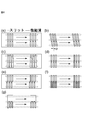
- FIG. 1 It is a figure which shows typically the row and the slit (3) of the plurality of microchannels (9) in the microdroplet / bubble generation device of this invention.
- An example of the droplet / bubble generation flow path in the first embodiment of the microdroplet / bubble generation device (100) of the present invention is shown.
- (A) is a top view of a component having a fine groove
- (b) is a developed perspective view of a component for liquid distribution.
- An example of the droplet / bubble generation flow path in the first embodiment of the microdroplet / bubble generation device (100) of the present invention is shown.
- (C) is a perspective view showing a part having a fine groove and a liquid distribution part (partial cross section) to be joined
- (d) is a top view when a part having a fine groove and a liquid distribution part are joined.
- An example of the droplet / bubble generation flow path in the first embodiment of the microdroplet / bubble generation device (100) of the present invention is shown.
- (E) and (f) are perspective views of how droplets are generated at the intersection of the slit and the microchannel.
- (a) is a perspective view showing a part having a fine groove and a liquid distribution part (partial cross section) to be joined
- (b) is a perspective view showing a part having a fine groove and a liquid distribution part (partial cross section) to be joined
- FIG. b) is a top view when the lid and the liquid distribution component having the fine groove processed are joined.
- (a) includes a component having fine grooves and an annular liquid distribution component (partial cross section) after assembling the three members.
- (B) is a top view when a part having a fine groove and a liquid distribution part are joined.
- (c) and (d) are diagrams showing how droplets are generated at the intersection of a slit and a microchannel.
- (a) is an annular liquid distribution component (partially cross-sectional) in which a lid and microgrooves after assembling the three members are machined. ), And (b) is a top view when the lid is joined to the liquid distribution component in which the fine groove is machined.
- the present invention is a microdroplet / bubble generation device (100).
- the microdroplet / bubble generation device (100) includes a plurality of rows of microchannels (9) and slits (3,4).
- the plurality of microchannels (9) are connected to the ends of the slits (3, 4) in the reference plane (S), and the slits (3, 4) are formed from the reference plane (S). It extends in the transverse direction of the plurality of microchannels (9) so as to move away from the plurality of microchannels (9).
- the plurality of microchannels (9) have a microchannel (9-1) on the first side and a microchannel on the second side on both sides of the connection portion (P) with the slits (3,4).
- the micro flow path (9-1) on the first side is connected to one of the continuous phase supply port (7) and the dispersed phase supply port (6), and the slits (3, 4) are connected to the one. It is connected to the other continuous phase supply port (7) or the dispersed phase supply port (6) different from the above, and the continuous phase (2) is supplied from the continuous phase supply port (7), and the dispersed phase supply port is supplied.
- the dispersed phase (1) is supplied from (6), and the dispersed phase (1) is supplied.
- the microchannel (9-2) on the second side is connected to the discharge port (8).
- the plurality of microchannels (9) are in contact with or near the connection point (P) with the slits (3,4) in the microchannel (9-2) on the second side.
- the present invention relates to a microdroplet / bubble generation device configured as described above.
- the "microdroplet / bubble generation device” means a microdroplet or bubble generation device.
- the device may be any device that produces at least one of microdroplets or microbubbles.
- the microdroplet / bubble generation device (100) of the present invention includes a plurality of rows of microchannels (9) and slits (3,4).
- the plurality of microchannels (9) exist in the reference plane (S).
- the plurality of microchannels (9) exist particularly on the reference plane (S).
- the plurality of microchannels (9) are channels through which any of a continuous phase (2), a dispersed phase (1), or a microdroplet / bubble product phase flows through the fine channel.
- the reference plane (S) can be the surface of an actual part, but the reference plane (S) does not have to be the surface of an actual part and is a virtual plane in the definition of the present invention.
- the shape of the cross section of the microchannel (9) is selected according to the material to be processed and the processing means, such as a rectangle, a trapezoid, a triangle, a polygon, a semicircle, a circle, an ellipse, and a semicircle. good.
- the width of the channel in the plan view of the rows of the plurality of microchannels (9) is, for example, 0.1 to 1000 ⁇ m, preferably 1 to 200 ⁇ m, and more preferably 10 to.
- the height of the flow path in the cross section perpendicular to the reference plane (S) of the rows of the plurality of micro flow paths (9) is, for example, 0.1 to 1000 ⁇ m, preferably 1 to 200 ⁇ m. , More preferably in the range of 10 to 100 ⁇ m.
- it can be operated within a predetermined range by the flow rate operation, it is possible to generate droplets or bubbles having a size corresponding to the dimensions of the microchannel (9).
- the size of the microchannel (9) is smaller than a predetermined size, the number of microchannels (9) in the device can be increased and the productivity of droplets / bubbles is improved, which is preferable.
- the size of the microchannel (9) is larger than a predetermined size, the pressure loss in the flow can be reduced, which is preferable. If the dimensions of the microchannel (9) are too small, clogging may easily occur, pressure loss may increase, and it may be difficult to flexibly control the flow rate. On the other hand, the dimensions of the microchannel (9) may be too small. If it is too large, the flow in the flow path is likely to be turbulent, and as a result, it becomes difficult to evenly supply the dispersed phase or the continuous phase to a plurality of micro flow paths, and the monodispersity of the generated droplets may be impaired. Therefore, the size of the microchannel (9) is preferably in the range of 0.1 to 1000 ⁇ m.
- the plurality of microchannels (9) are connected to the ends of the slits (3,4) in the reference plane (S), and the slits (3,4) are connected to the plurality of microchannels from the reference plane (S). It extends in the transverse direction of (9) so as to move away from the plurality of microchannels (9).
- the slits (3, 4) have a linear slit end face having a width and an axis (slit length) having a dimension larger than the width and the dimension of the width in the reference plane (S), and the reference plane (S) is one of them. It is a plane in which a plurality of rows of microchannels (9) exist on the side, particularly on the side, and the slits (3, 4) are from the reference plane (S) to the reference plane (S) with the reference plane (S) as the end. Can extend to the other side in the transverse direction, especially below (the slit in the present invention has a slit-shaped end face in the reference plane (S), and the slit-shaped cross section has a reference plane (S).
- the shape of the slit end face is not particularly limited, and may be, for example, a straight line or an annular shape.
- the dimension of the slits (3,4) in the transverse direction of the reference plane (S) can be said to be the depth (height) of the slits (3,4).
- the rows of the plurality of microchannels (9) exist on one side of the reference plane (S), particularly above, and the rows of the plurality of microchannels (9) terminate at the reference plane (S). It may be connected to the slits (3, 4) by a reference plane (S). At this time, the plurality of microchannels (9) have connection points (P) with slits (3, 4) in the reference plane (S).
- FIG. 1 schematically shows an example of rows and slits (dispersed phase supply slit (3)) of a plurality of microchannels (9).
- FIG. 1A is a schematic view of slits (3)
- FIG. 1B is a schematic view of rows of a plurality of microchannels (9) viewed from a direction perpendicular to a reference plane (S).
- FIG. 1A may be an end view of the slit (3) in the reference plane (S).
- FIG. 1 (c) shows a microdroplet / bubble generating device having both a slit (3) and a row of a plurality of microchannels (9) in a reference plane (S) as in FIGS. 1 (a) and 1 (b).
- FIG. 1 (d) is a schematic view of the device of FIG. 1 (c) as viewed from the side.
- the plurality of microchannels (9) have a narrowed portion (N) in which the width of the channel is narrowed, and in FIGS. 1 (c) and 1 (d), the narrowed portion (N) is a slit. It is near the connection point (P) between (3) and the microchannel (9).
- the narrowed portion (N) may be in contact with the connection portion (P) between the slit (3) and the microchannel (9), and there may be no gap between the two.
- the surface having the slit end surface is in contact with the lower surface of the micro flow path (9), and the surface having the slit end surface and the lower surface of the micro flow path (9) is the reference plane (S). be.
- the dispersed phase (1) is supplied from the slit (3)
- the continuous phase (2) is supplied from the left side of the connection point (P) of the micro flow path (9)
- the slit (3) is supplied.
- the device having the structure described with reference to FIGS. 1 (a) to 1 (d) includes a plurality of parts having slits (3) on the slit end face as shown in FIG. 1 (a) and a plurality of devices as shown in FIG. 1 (b). It can be manufactured by laminating parts having a row of fine grooves for forming the microchannel (9) to form a structure as shown in FIGS. 1 (c) and 1 (d). Further, if a row of a plurality of fine grooves as shown in FIG. 1 (b) is formed on the surface of the part having the slit end face of the part having the slit (3) formed as shown in FIG. 1 (a) (slits and fine grooves).
- the formation order of the parts may be reversed), and the surface of the part has slits and a row of a plurality of fine grooves as shown in FIG. 1 (c). ), A device having a plurality of rows of microchannels (9) and slits (3) is formed.
- the surface of the component having the slit and the row of the plurality of microgrooves that is, the upper surface of the plurality of microgrooves is not the reference plane (S), but the reference planes (S) are plural.
- (9) that is, a flat surface that joins with a slit on the lower surface of a plurality of microgrooves. Therefore, the reference plane (S) in this case is not the surface of the component but a virtual plane.
- the microdroplet / bubble generation device (100) of the present invention has a dispersed phase supply port (6), a continuous phase supply port (7), and a discharge port (8).
- the dispersed phase supply port (6) is a transport path for supplying the dispersed phase to the plurality of microchannels (9), and has connection points (P) with the plurality of microchannels (9).
- the continuous phase supply port (7) is a transport path for supplying the continuous phase to the plurality of microchannels (9), and has a connection point (P) with the plurality of microchannels (9).
- the discharge port (8) is a transport path for discharging droplets / bubble products generated from the plurality of microchannels (9), and has connection points (P) with the plurality of microchannels (9).
- At least one slit is any one or more of the continuous phase supply slit (4) and the dispersed phase supply slit (3), and the continuous phase supply is here.
- the slit (4) for the dispersed phase and the slit (3) for supplying the dispersed phase form a part of the dispersed phase supply port (6) and the continuous phase supply port (7), respectively, and a plurality of microchannels ( The end point is the connection point (P) with 9).
- the microchannels (9) of the plurality of microchannels (9) are located on both sides of the connection points (P) with the specific slits (3,4). It has a microchannel (9-1) on the first side and a microchannel (9-2) on the second side.
- the micro flow path (9-1) on the first side is connected to one of the continuous phase supply port (7) and the dispersed phase supply port (6), and the specific slits (3, 4) are connected to the continuous phase supply port (3, 4). It is connected to the other of the port (7) and the dispersed phase supply port (6), which is different from the one.
- the continuous phase (2) is supplied from the continuous phase supply port (7)
- the dispersed phase (1) is supplied from the dispersed phase supply port (6)
- the microchannel (9-2) on the second side is a discharge port. It is connected to (8).
- the specific slits are the dispersed phase supply port (6) or the continuous phase supply port (7) as the connection positions with the plurality of micro flow paths (9). It is arranged so as to be sandwiched between the discharge port (8) and the discharge port (8).
- the specific slits (3, 4) are the continuous phase supply slits (4), they are sandwiched between the dispersed phase supply port (6) and the discharge port (8), and the specific slits (3, 4) are dispersed.
- the phase supply slit (3) it is sandwiched between the continuous phase supply port (7) and the discharge port (8).
- the plurality of microchannels (9) have the specific slits (3,4) in the plane (reference plane (S)) perpendicular to the specific slits (3,4) where the ends of the specific slits (3,4) exist. It is arranged so as to connect the terminal of the above and the supply ports (6, 7) and the discharge port (8) on both sides thereof.
- the supply ports (6, 7) and discharge ports (8) on both sides of the specific slits (3, 4) are the closest supply ports (6, 7) and discharge ports (6, 7) on both sides of the specific slits (3, 4). 8).
- the dispersed phase (1) is supplied from the dispersed phase supply port (6), and the continuous phase (2) is supplied from the continuous phase supply port (7). It is supplied and one of the dispersed phase (1) and the continuous phase (2) is distributed to a plurality of microchannels (9).
- being distributed to a plurality of microchannels (9) means that the dispersed phase (1) and / or the continuous phase supplied from the dispersed phase supply port (6) and / or the continuous phase supply port (7) is used.
- the plurality of microchannels (9) are first on both sides of the connection points (P) with the specific slits (3,4). It has a microchannel (9-1) on the side and a microchannel (9-2) on the second side, respectively.
- the micro flow path (9-1) on the first side is connected to one of the continuous phase supply port (7) and the dispersed phase supply port (6), and the specific slits (3, 4) are connected to the continuous phase supply port (3, 4). 7) and the dispersed phase supply port (6) are connected to the other, which is different from the one.
- the plurality of microchannels (9) are in contact with or in the vicinity of the connection points (P) with the specific slits (3,4) in the microchannel (9-2) on the second side. It has a narrowed portion (N) whose cross-sectional area is locally narrowed.
- the microchannel (9-2) on the second side is adjacent to or near the connection point (P) with the specific slits (3,4), that is, at the connection point (P). Since it has a narrowed portion (N) in which the cross-sectional area of the flow path is locally narrowed almost continuously (hereinafter, for the sake of simplicity, it is also referred to as “nearby", that is, “continuously” including almost continuous), it is micro.
- the continuous phase (2) and the dispersed phase (1) associated at the connection point (P) between the flow path (9) and the specific slits (3, 4) are continuous of the continuous phase (2) and the dispersed phase (1), respectively.
- the dispersed phase (1) is still completely sheared by the flow of the continuous phase (2) and flows into the constriction (N) without forming droplets or bubbles, while basically maintaining the normal flow. be able to.
- the narrowed portion (N) continuously existing at the connection point (P) between the micro flow path (9) and the specific slits (3, 4) the flow of the continuous phase (2) and the flow of the dispersed phase (1) are Since the cross-sectional area of the flow path is narrowed, the flow velocity is locally increased.
- the dispersed phase (1) is sheared by the flow of the continuous phase (2) in which the flow velocity is increased in the narrowed portion (N), and droplets or bubbles of the dispersed phase (1) are generated in the narrowed portion (N).
- "a droplet or a bubble is generated in the narrowed portion” means that a droplet or a bubble is generated in the vicinity of the exit of the narrowed portion (N) and the narrowed portion (N).
- the dispersed phase (1) is sheared by the accelerated flow of the continuous phase (2) in the constricted portion (N) having a small cross-sectional area, and the dispersed phase (1) is sheared.
- the size of the droplets or bubbles of the dispersed phase (1) generated is narrowed if the flow rates of the continuous phase (2) and the dispersed phase (1) are the same.
- the size can be smaller and the density of droplets or bubbles (number density) can be increased as compared with the case where there is no portion (N). ii) Further, in the device having the narrowed portion (N) of the present invention, the portion of the narrow flow path (narrowed portion (N)) that causes pressure loss is minimized, and there is no narrowed portion (N), which is simply the size. Since the pressure loss can be significantly reduced compared to the case of using a small flow path, the device as a whole can generate droplets or bubbles with a lower pressure loss and a lower risk of clogging. ..
- the generation site of the droplet or the bubble is set to the second side from the specific slit (3, 4) as compared with the case where there is no narrowed portion (N).
- the transition can be made to the downstream side of the microchannel (9-2).
- irregular microconcavo-convex shapes that occur during processing, such as minute defects and burrs, at the corners of the specific slits (3, 4) that are in contact with the microchannel (9-2) on the second side become droplets or The effect of disturbing the formation of bubbles can be suppressed.
- the continuous phase (2) and the dispersed phase (1) meet, and the continuous phase (2) becomes the dispersed phase (1).
- a double-phase flow of a continuous phase (2) and a dispersed phase (1) usually, a laminar flow in which the flow of the continuous phase (2) partially surrounds the flow of the dispersed phase (1). Then, it flows toward the narrowed portion (N) of the microchannel (9-2) on the second side.
- the dispersed phase (1) is sheared by the flow of the continuous phase (2) as a driving force in the microchannel (9-2) on the second side, and the dispersed phase (1) becomes Droplets or bubbles are generated.
- the connection point (P) of the plurality of microchannels (9) and the slits (3, 4) it is formed at the connection point (P).
- the double-phase flow of the continuous phase (2) and the dispersed phase (1) flows into the narrowed portion (N) in a state where droplets or bubbles of the dispersed phase (1) are not generated, and the flow flows into the narrowed portion (N).
- the dispersed phase (1) is sheared by the flow of the continuous phase (2), and the droplets of the dispersed phase (1) or the droplets of the dispersed phase (1) are formed mainly on the outlet side of the narrowed portion (N). Bubbles are generated.
- the liquid flows into the constricted portion (N) before the droplets or bubbles of the dispersed phase (1) are generated in the microchannel (9-2) on the second side.
- the cross-sectional area of the flow path is locally narrowed at a specific location (in contact with or near the connection portion (P)) of the microchannel (9-2) on the second side. It is the part that is present.
- the shape of the cross section of the narrowed portion (N) may be selected according to the material to be processed and the processing means, such as a rectangle, a trapezoid, a triangle, a polygon, a semicircle, a circle, an ellipse, and a semicircle.
- the cross-sectional area of the flow path is locally narrower than the cross-sectional area of the micro flow path (9-2) on the second side, and the flow path in the plan view of the rows of the plurality of micro flow paths (9).
- the width of the flow path may be narrowed, or the height of the flow path in the cross section perpendicular to the reference plane (S) of the rows of the plurality of micro flow paths (9) may be narrowed, or both.
- the plurality of microchannels (9) are narrowed at the center in the width or height direction, but they may be narrowed at any position.
- the cross-sectional area of the constriction (N) is 1/100 to 1 / 1.5 of the cross-sectional area of the microchannel (9-2) on the second side other than the constriction (N). It may be preferably in the range of one-tenth to one-half, more preferably one-fifth to one-third.
- the cross-sectional area of the narrowed portion (N) is the average value of the cross-sectional area of the narrowed portion (N). If the cross-sectional area of the microchannel in the portion between the connection portion (P) and the narrowed portion (N) is larger than the cross-sectional area of the narrowed portion (N), there is no problem, and there is no problem with the microchannel of the other portion.
- the cross-sectional area of the microchannel (9-2) which is a reference when measuring the cross-sectional area of the narrowed portion (N), is the second side opposite to the connection point (P) of the narrowed portion (N). It is the cross-sectional area of the microchannel (9-2) on the side of 2.
- the microchannel (9-2) on the second side is usually a straight line and its cross-sectional area is constant, but when the cross-sectional area changes in the flow path direction, the second side
- the cross-sectional area of the portion of the microchannel (9-2) near the narrowed portion (N) is used.
- the dimension of the flow direction of the micro flow path (9-2), which is a reference when measuring the cross-sectional area of the narrowed portion (N) is the width (micro) of the slit end face in the immediate vicinity of the narrowed portion (N). It is sufficient if the length is twice or more, further three times or more, or five times or more the dimension in the flow direction of the flow path).
- the cross section of the constriction (N) is smaller than the cross section of the microchannel (9-2) on the second side, especially if it is smaller than 1 / 1.5, the size of the droplet or bubble generated will be determined. It is possible to obtain the effect of providing the narrowed portion (N), such as making the size smaller and increasing the density (number) of the generated droplets or bubbles.
- the cross section of the narrowed portion (N) is not too small compared to the cross section of the microchannel (9-2) on the second side, and in particular, the microchannel on the second side other than the narrowed portion (N). When it is 1/100 or more of the cross-sectional area of the above, the pressure loss does not become too large, which is preferable.
- the size of the constriction is too small for the size of the microchannel, the pressure loss due to the constriction increases, which may cause clogging, and the size of the droplets generated in the constriction is controlled. It becomes spicy, and more specifically, small droplets close to the cross-sectional size of the constriction can be formed, but larger droplets close to the cross-sectional size of the microchannel are difficult to generate (the tip of the dispersed phase is inside the microchannel). It may be sheared before it grows large).
- the square root of the cross-sectional area of the constriction (N) may be in the range of 0.1 to 1000 ⁇ m, preferably 1 to 100 ⁇ m, more preferably 10 to 50 ⁇ m. ..
- the length of the narrowed portion (N) in the flow path direction is 0.01 to 10 times, preferably 0.1 to 2 times the square root of the area of the cross-sectional dimension of the micro flow path (9-2) on the second side. It may be in the range of times, more preferably 0.2 to 1 times.
- the area of the cross section of the microchannel (9-2) on the second side is measured as described above.
- the length of the narrowed portion (N) in the flow path direction is a certain value or more, especially when it is 0.01 times or more of the square root of the cross-sectional dimension area of the micro flow path (9-2) on the second side. It is preferable because the structure of the narrowed portion (N) can be made thicker and stronger.
- the cross-sectional area is narrow, especially if it is 10 times or less the square root of the cross-sectional dimension area of the microchannel (9-2) on the second side. Since the size of the narrowed portion (N) is small, the pressure loss in the narrowed portion (N) can be reduced, which is preferable. If the length of the constriction (N) in the flow path direction is too small compared to the cross-sectional size of the microchannel, the constriction is a very thin film-like structure (for example, the length for a 100x100 ⁇ m channel).
- the length of the narrowed portion (N) in the flow path direction is in the range of 0.1 to 1000 ⁇ m, preferably 1 to 200 ⁇ m, and more preferably 10 to 100 ⁇ m. You can do it.
- the narrowed portion (N) is in contact with or near the connection portion (P) of the plurality of microchannels (9) and the slits (3, 4) (almost continuously to the connection portion (P)).
- the distance from the connection point (P) to the constriction (N) is 5 times or less, preferably 2 times or less, more preferably 1 time or less of the square root of the cross-sectional area of the microchannel (9) on the second side. (Both may include zero).
- the cross-sectional area of the narrowed portion (N) is the average value of the cross-sectional area of the narrowed portion (N).
- the narrowed portion (N) is usually used. It may be the same as the cross-sectional area of the microchannel (9-2) on the second side opposite to the connection point (P). Therefore, the cross-sectional area of the microchannel (9-2), which is a reference when measuring the cross-sectional area of the narrowed portion (N), is the second side opposite to the connection point (P) of the narrowed portion (N). It is the cross-sectional area of the microchannel (9-2) on the side of 2.
- the microchannel (9-2) on the second side is usually a straight line and its cross-sectional area is constant, but when the cross-sectional area changes in the flow path direction, the second side
- the cross-sectional area of the portion of the microchannel (9-2) near the narrowed portion (N) is used.
- the dimension of the flow direction of the micro flow path (9-2), which is a reference when measuring the cross-sectional area of the narrowed portion (N) is the width (micro) of the slit end face in the immediate vicinity of the narrowed portion (N). It is sufficient if the length is twice or more, further three times or more, or five times or more the dimension in the flow direction of the flow path).
- the droplet size may be divided (non-uniformly) at the constriction portion (N), and as a result, the monodispersity of the droplet size may be impaired. It is preferably 5 times or less the square root of the cross-sectional area of the microchannel (9) on the 2 side.
- the distance from the connection point (P) of the plurality of microchannels (9) and the slits (3,4) to the narrowed portion (N) is 1000 ⁇ m or less (including zero). ), It may be preferably 400 ⁇ m or less (including zero), and more preferably 200 ⁇ m or less (including zero).
- the distance from the slits (3, 4) to the constriction (N) may be smaller than the specific length as described above, and may not be the same in all the microchannels in the row of the plurality of microchannels.
- This distance may be zero and depends on the flow velocity condition, but when this distance is increased after a certain range, droplets or bubbles of the dispersed phase (1) are generated before the flow from the slit side enters the narrowed portion (N). It becomes easier to do.
- the narrowed portion (N) of the microchannels (9) will be the slits (3,4).
- the stenosis (N) becomes integral with the slits (3,4), and the end of the stenosis (N) coincides with the position in contact with the connection (P) with the slits (3,4). .. Therefore, at this time, the distance from the connection portion (P) to the narrowed portion (N) becomes zero.
- a plurality of microchannels (9) and slits (3, 4) can be provided separately on both sides of the reference plane (S), and in this case, in the plan view of the reference plane (S).
- a part of the narrowed portion (N) can exist overlapping with the connecting portion (P).
- the connecting portion (P) As described above, in the plan view of the reference plane (S), when a part of the narrowed portion (N) overlaps with the connecting portion (P), the flow of the continuous phase (2) and the dispersed phase (1) flows. Since the road is continuous at the connection point (P), in the present invention, the distance from the connection point (P) to the narrowed portion (N) is zero, that is, the narrowed portion (N) is the connecting point (P). It is considered to be adjacent to.
- the width of the slit (3,4) is, for example, in the range of 1 to 1000 ⁇ m, preferably 10 to 500 ⁇ m, and more preferably 20 to 200 ⁇ m. It may be inside.
- the width of the slits (3, 4) is equal to or larger than a certain value, the pressure loss can be reduced, which is preferable.
- the width of the slits (3, 4) is not more than a certain value, the stability of the flow is increased, and it is preferable for forming fine droplets or bubbles.
- the width of the slits (3, 4) is preferably 1 to 1000 ⁇ m at the end of the slits (3,4) in the reference plane (S).
- the product is on the second side. It is collected from the discharge port (8) connected to the micro flow path (9-2).
- the discharge port (8) is located on the side opposite to the connection point (P) between the micro flow path (9) and the slit (3, 4) with respect to the narrowed portion (N) of the micro flow path (9-2) on the second side. It is connected.
- the portion where the discharge port (8) connects to the microchannel (9-2) on the second side of the row of the plurality of microchannels (9) is an additional slit (5) or a cylindrical hole (5).
- the additional slit (5) or the cylindrical hole (5-1) constitutes a part of the discharge port (8).
- the additional slit (5) or the cylindrical hole (5-1) constitutes a part of the discharge port (8).
- the additional slit (5) or the cylindrical hole (5-1) constitutes a part of the discharge port (8).
- the connection point (P) between the specific slits (3, 4) and the microchannels (9) on both sides thereof is a location where the specific slit and the microchannels (9-1, 9-2) on both sides of the specific slit meet.
- the positions where the microchannels (9-1, 9-2) on both sides meet are not necessarily the same positions of the specific slits (3, 4), but may be positioned different from each other (see FIG. 4). ..
- the dispersed phase (1) and the continuous phase (2) are supplied to the specific slits (3, 4) and the microchannel (9-1) on one side (first side) thereof, and the dispersed phase (1) is supplied.
- the specific slits (3, 4) form a part of the dispersed phase supply port (6) or the continuous phase supply port (7) as described above, but at the same time, the micro flow paths on both sides thereof.
- the specific slit (dispersed phase or continuous phase supply port) and the supply ports / discharge ports on both sides thereof are not necessarily different supply ports / discharge ports, and are not necessarily different supply ports / discharge ports.
- One or both of the supply ports / discharge ports on both sides (next to each other) may be the same supply port / discharge port.
- the number of specific slits may be one or two or more.
- the dispersed phase supply port (No. 2) of the dispersed phase supply port (No. 1) A constriction (N) is provided on at least one of the side and the discharge port side of the dispersed phase supply port (No. 2), particularly both.
- the continuous phase supply port (7), the dispersed phase supply port (6), and the discharge port (8) other than the specific slits (3, 4) are also microchannels.
- the end connected to (9) may be a slit (referred to as an additional slit).
- the additional slit is any one or more of the continuous phase supply slit (4), the dispersed phase supply slit (3), and the discharge port (8), and here, the continuous phase supply slit (4) and the dispersed phase
- the supply slit (3) and the discharge slit (5) form a part of the dispersed phase supply port (6), the continuous phase supply port (7), and the discharge port (8), respectively, and a plurality of them.
- the connection point (P) with the micro flow path (9) of the above is terminated. Therefore, in the microdroplet / bubble generation device (100) of the present invention, there is at least one specific slit (3,4), but the number of slits (3,4,5) is the specific slit (3,4).
- the continuous phase supply port (7) is arranged in the order of ⁇ continuous phase supply port-dispersed phase supply port-discharge port> on the reference plane (S). )
- the end of the outlet (8) can optionally be additional slits.
- the end of the continuous phase supply port (7) and the discharge port (8) may be optionally a cylindrical hole (5-1) or the like.
- the liquid forming the dispersed phase (1) and the continuous phase (2) is an organic compound or water.
- the organic compound is not particularly limited, but preferred examples thereof include alkanes such as decane and octane, halogenated hydrocarbons such as chloroform, aromatic hydrocarbons such as toluene, and fatty acids such as oleic acid.
- alkanes such as decane and octane
- halogenated hydrocarbons such as chloroform
- aromatic hydrocarbons such as toluene
- fatty acids such as oleic acid.
- Known polymerizable monomers, oligomers or polymers preferably acrylate-based monomers, styrene-based monomers and the like.
- the combination of dispersed phase (1) and continuous phase (2) is usually oil-in-water type (O / W type), oil-in-oil type (O / O type), or water-in-oil type (O / O type). W / O type).
- the dispersed phase (1) is a gas
- the continuous phase (2) is a liquid composed of an aqueous phase or an organic phase.
- the gas is not particularly limited, but preferred examples thereof include air, oxygen, nitrogen, carbon dioxide, and argon gas.
- the flow rates of the dispersed phase (1) and the continuous phase (2) per single microchannel (9) are usually selected from about 0.001 mL to 10 mL / hour, although it depends on the type and the like.
- the microdroplet / bubble generation device (100) of the present invention includes a plurality of parallel linear microgroove array substrates (10) having a rectangular cross-sectional shape, and a liquid or gas distribution component (20). It is composed of (Fig. 2-1 to Fig. 2-3). With reference to FIGS. 2-1 (a) and 2-2 (d), the microgroove array substrate (also referred to as a microchannel array) (10) has 16 rectangular cross sections (width 100 ⁇ m, height 100 ⁇ m).
- each of the fine groove array substrate has a length of 4.875 mm or more on both sides of the central axis (C) in the fine groove direction.
- Each microgroove (10-1) is within a range of 125 ⁇ m to 175 ⁇ m from the central axis (C) of the microgroove array substrate (10) toward one end (right side of FIG. 2-1 (a)).
- the narrowed portion (N) At a distance position, there is a narrowed portion (N) in which the cross-sectional area of the groove is narrowed, and the narrowed portion (N) has a rectangular cross section (width 50 ⁇ m, height 100 ⁇ m) and a length 50 ⁇ m.
- the liquid or gas distribution component (20) has four members (20-1) having a width of 30 mm, a length of 30 mm, and a height of 8 mm. , 20-2, 20-3, 20-4).
- the uppermost first member (20-1) has a continuous phase supply slit (4), a dispersed phase supply slit (3), a product discharge slit (5), and a discharge port (8).
- the second member (20-2) in the second stage from the top has a continuous phase supply slit (4), a dispersed phase supply slit (3), and a continuous phase supply port (7).
- the third member (20-3) in the third stage from the top has a dispersion phase supply slit (3) and a dispersion phase supply port (6).
- the lowermost fourth member (20-4) is a flat plate for closing the through hole formed at the bottom by the dispersion phase supply slit (3) of the third member (20-3).
- FIG. 2-2 (c) shows a cross-sectional perspective view when the first to fourth members of the liquid or gas distribution component (20) are combined.
- the supplied dispersed phase (1) and continuous phase (2) flow from the lower layer through the slit-shaped flow paths (3, 4) inside the component (20) to the upper part of the liquid or gas distribution component (20). Is supplied.
- the dispersed phase (1) is supplied from the dispersed phase supply port (6) to the dispersed phase supply slit (3) in the third member (20-3), and the continuous phase (2) is supplied to the second member (20).
- the continuous phase supply port (7) is supplied to the continuous phase supply slit (4), and the continuous phase (2) and the dispersed phase (1) are sent upward in each slit (3, 4). ..
- the portions other than the slit are indicated as the dispersed phase supply port (6), the continuous phase supply port (7), and the discharge port (8). Is functionally part of the dispersed phase supply port (6), continuous phase supply port (7) or discharge port (8), as described above (similar to the following aspects). , Do not repeat.).
- the fine groove array substrate (10) is provided with three slits on the liquid or gas distribution component (20), namely, a continuous phase supply slit (4), a dispersed phase supply slit (3), and a product discharge slit (5).
- 2-2 (d) shows a plan view of the fine groove array substrate (10) that has been aligned with) and combined.
- the long side width at the slit end portion (slit end face) is 5 mm
- the short side width is 250 ⁇ m
- the pitch between the slits (distance between centers) is 3 mm
- the slits are 2.75 mm apart.
- N There is a narrowed portion (N) having a width of 50 ⁇ m and a length of 50 ⁇ m at intervals of 0 to 50 ⁇ m on the product discharge slit (5) side from the dispersed phase supply slit (3).
- the continuous phase (2) is supplied to the upper slit (4), the dispersed phase (1) is supplied to the central slit (3), and the continuous phase (2) is a fine groove (2).
- FIGS. 2-3 (e) and (f) show how droplets or bubbles are generated in the apparatus (100).
- the dispersed phase (1) is entrained in the flow of the continuous phase (2) at the connection point (P) between the dispersion phase supply slit (3) and the microchannel (9), and the continuous phase (2) and the dispersed phase (1)
- Each of the flows enters the narrowed portion (N) while being continuous, and the flow velocity of the flow of the continuous phase (2) and the dispersed phase (1) increases in the narrowed portion (N) where the cross-sectional area of the flow path is narrowed.
- the continuous phase (2) As a result of the dispersion phase (1) being sheared at the location where the cross-sectional area of the flow path at the outlet of the constriction (N) is widened by the flow of the continuous phase (2) with increased flow velocity, the continuous phase (2) and When the flow rate conditions of the dispersed phase (1) are the same, smaller and denser (number) droplets or bubbles are generated as compared with the case where there is no narrowed portion (N).
- the product is discharged from the discharge port (8) through the discharge slit (5).
- the second embodiment of the present invention is the same as the first embodiment, but the arrangement of the continuous phase supply slit (4) and the dispersed phase supply slit (3) in the liquid or gas distribution component (20) is reversed.
- the fine groove array substrate (10) is the same as that of the first embodiment (FIG. 3-1 (b)).
- the liquid or gas distribution component (20) is composed of four members (20-1, 20-2, 20-3, 20-4). With reference to FIG. 3-1 (b), the uppermost first member (20-1) has a continuous phase supply slit (4), a dispersed phase supply slit (3), and a product discharge slit (5). , And a discharge port (8).
- the second member (20-2) in the second stage from the top has a continuous phase supply slit (4), a dispersed phase supply slit (3), and a dispersed phase supply port (6).
- the third member (20-3) in the third stage from the top has a continuous phase supply slit (4) and a continuous phase supply port (7).
- the fourth member (20-4) at the bottom is a flat plate for closing the through hole formed at the bottom by the continuous phase supply slit (4) of the third member (20-3) (FIG. 3-1). (A)).
- FIG. 3-1 (a) shows a cross-sectional perspective view when the first to fourth members of the liquid or gas distribution component (20) are combined.
- the supplied dispersed phase (1) and continuous phase (2) flow through a slit from the lower layer and are supplied to the upper part of the liquid or gas distribution component (20). That is, the dispersed phase (1) is supplied from the dispersed phase supply port (6) to the dispersed phase supply slit (3) in the second member (20-2), and the continuous phase (2) is supplied to the third member (20). In -3), the continuous phase supply port (7) is supplied to the continuous phase supply slit (4), and the continuous phase (2) and the dispersed phase (1) are sent upward in each slit.
- the microgroove array substrate (10) is combined with three slits on the liquid or gas distribution component (20), namely the continuous phase supply slit (4), the dispersed phase supply slit (3) and the discharge slit (5).
- FIG. 3-1 (b) shows the aligned and coupled ones viewed from above of the fine groove array substrate (10) in a plan view.
- the long side width at the end of the slit is 5 mm
- the short side width is 250 ⁇ m
- the pitch between the slits (distance between centers) is 3 mm
- the slits are 2.75 mm apart.
- the microgroove (10-1) has a narrowed portion (N) on the side of the product discharge slit (5) closest to the continuous phase supply slit (4).
- the dispersed phase (1) is supplied to the upper slit (3), the continuous phase (2) is supplied to the central slit (4), and the dispersed phase (1) is a fine groove (1). It is supplied to the microchannel (9) formed from 10-1), and droplets or air bubbles are supplied at the connection point (P) and the narrowed portion (N) between the continuous phase supply slit (4) and the microchannel (9). Is generated, and the produced product is discharged through the lower slit (5) through the microchannel (9).
- FIGS. 3-2 (c) and 3-2 (d) show how droplets or bubbles are generated in the apparatus.
- the dispersed phase (1) is entrained in the flow of the continuous phase (2), and the continuous phase (2) and the dispersed phase (1) are taken.
- the continuous phase (2) As a result of shearing the dispersed phase (1) at the point where the cross-sectional area of the flow path at the outlet of the constriction (N) expands due to the flow of the continuous phase (2) with increased flow velocity, the continuous phase (2) When the flow rate conditions of the dispersed phase (1) are the same, smaller and denser (number) droplets or bubbles are generated as compared with the case where there is no narrowed portion (N).
- the product is discharged from the discharge port (8) through the discharge slit (5).
- FIG. 4 shows the groove shape of the part having the fine groove (10-1) joined to the liquid or gas distribution part (20) in the first and second embodiments of the present invention.
- FIG. 4A shows a case where three slits (broken line) are vertically bridged by a row of linear microchannels (solid line), and
- FIG. 4B shows a case where the three slits (broken line) are linear.
- the width of the microchannels (solid lines) bridging the three slits changes continuously in FIG. 4 (c). If this is the case.
- the width of the fine groove may change discontinuously.
- FIGS. 4 (d) to 4 (f) show the case where the micro flow path (solid line) connecting the sandwiched slit (broken line) and the slits on both sides (broken line) is divided, and FIG. 4 (d) shows.
- FIG. 4 (e) shows the case where the position and the size match
- FIG. 4 (e) shows the case where the position is misaligned
- FIG. 4 (f) shows the case where the number correspondence is not 1: 1.
- FIG. 4 (g) shows a case where the rows of the microchannels (solid lines) bridging are partially joined to each other.
- the features of FIGS. 4A to 4G may be arbitrarily combined.
- the microgroove array substrate (10) is a silicone resin (10) from a mold prepared using, for example, SU-8 (Nippon Kayaku Co., Ltd.), which is a negative photoresist, on a Si substrate. It can be produced by transferring the pattern to PDMS: polydimethylsiloxane).
- the liquid or gas distribution component (20) can be manufactured, for example, by machining a stainless steel material (SUS304). Further, the slit-shaped through hole of the liquid or gas distribution component (20) can be produced by, for example, wire electric discharge machining.
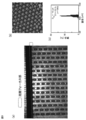
- W / O droplets are generated by feeding, for example, a dispersed phase such as pure water and a continuous phase such as a fluorine-based oil to which 1 wt% of a surfactant is added. ..
- a glass syringe and a syringe pump can be used to feed the dispersed phase and the continuous phase.
- an upright optical microscope and a high-speed video camera in combination.
- Embodiment 3 of the present invention is similar to Embodiment 1, but in Embodiment 3, a row of a plurality of microchannels (9) is formed on the liquid or gas distribution component (21) side, and the embodiment 1
- the component corresponding to the microgroove array substrate (10) is merely a lid (11) for sealing the slits (3, 4, 5) of the liquid or gas distribution component (21) and the microgroove (11-1). ..
- the liquid or gas distribution component (21) is composed of four members (21-1, 21-2, 21-3, 21-4) (FIG. 5).
- the first member (21-1) at the uppermost portion includes a slit for supplying a continuous phase (4), a slit for supplying a dispersed phase (3), a slit for discharging a product (5), and a fine groove (11) bridging each slit with each other. It has an array of -1) and a discharge port (8) connected to a product discharge slit (5).
- the fine groove (11-1) has a narrowed portion (N) slightly spaced from the dispersed phase supply slit (3) on the product discharge slit (5) side of the dispersed phase supply slit (3). ..
- the second member (21-2) in the second stage from the top has a continuous phase supply slit (4), a dispersed phase supply slit (3), and a continuous phase supply port (7).
- the third member (21-3) in the third stage from the top has a dispersion phase supply slit (3) and a dispersion phase supply port (6).
- the lowermost fourth member (21-4) is a flat plate for closing the through hole formed at the bottom by the dispersion phase supply slit (3) of the third member (21-3).
- FIG. 5A shows a cross-sectional perspective view of the liquid or gas distribution component (21) when the first to fourth members are combined.
- the supplied dispersed phase (1) and continuous phase (2) flow through a slit from the lower layer and are supplied to the upper part of the liquid or gas distribution component (21). That is, the continuous phase (2) is supplied from the continuous phase supply port (7) to the continuous phase supply slit (4) in the second member (21-2), and the dispersed phase (1) is supplied to the third member (21).
- the dispersion phase supply port (6) is supplied to the dispersion phase supply slit (3), and the continuous phase (2) and the dispersion phase (1) are sent upward in each slit.
- FIG. 5 (b) shows a plan view of the joined lid (11) for the purpose of forming the gas from above the lid (11).
- the continuous phase (2) is supplied to the upper slit (4)
- the dispersed phase (1) is supplied to the central slit (3)
- the continuous phase (2) is the fine groove (11-).
- the product supplied to the microchannel (9) formed from 1) and generated at the connection point (P) and the narrowed portion (N) between the dispersed phase supply slit (3) and the microchannel (9) is micro.
- FIG. 5-2 (c) shows how droplets or bubbles are generated in the apparatus.
- the dispersion phase (1) is taken along with the flow of the continuous phase (2), and the continuous phase (2) and the dispersion phase (1) are taken.
- the flow of the continuous phase (2) with increased flow velocity causes the dispersed phase (1) to be sheared at the point where the cross-sectional area of the flow path at the outlet of the constriction (N) expands, resulting in the continuous phase (2).
- the flow rate conditions of the dispersed phase (1) are the same, smaller and denser (number) droplets or bubbles are generated as compared with the case where there is no narrowed portion (N).
- the product is discharged from the discharge port (8) through the discharge slit (5).
- the fourth embodiment of the present invention is the same as the third embodiment, but the arrangement of the continuous phase supply slit (4) and the dispersed phase supply slit (3) in the liquid or gas distribution component (21) is reversed. It is a different aspect in that it is.
- the relationship between the fourth embodiment and the third embodiment is the same as the relationship between the second embodiment and the first embodiment, and the detailed description of the fourth embodiment will not be described repeatedly.
- the sealing lid (11) is made of a transparent member such as a silicone resin (PDMS: polydimethylsiloxane), an acrylic resin, or glass.
- the liquid or gas distribution component (21) is manufactured by machining, for example, a stainless steel material (SUS304). Further, the slit-shaped through hole of the liquid or gas distribution component (20) can be produced by, for example, wire electric discharge machining. Further, the fine groove that bridges the slits can be produced by machine cutting, laser processing, etching, or the like.
- W / O droplets are generated by feeding, for example, a dispersed phase such as pure water and a continuous phase such as a fluorine-based oil to which 1 wt% of a surfactant is added. ..
- a glass syringe and a syringe pump can be used to feed the dispersed phase and the continuous phase.
- the liquid or gas distribution component (22) is composed of three members (22-1, 22-2, 22-3) (FIGS. 6-1 and 6-2). ..
- the liquid or gas distribution component (22) is located at the bottom of the substrate (12) having the microgrooves (12-1) and is the top first member (22-) with a continuous phase supply port (7).
- FIG. 6-1 shows a cross-sectional perspective view of the liquid or gas distribution component (22) when the first to third members are combined.
- the supplied dispersed phase (1) and continuous phase (2) flow from the lower layer through the annular slits (3, 4) and are supplied to the upper part of the liquid or gas distribution component (22).
- the dispersed phase (1) is supplied from the dispersed phase supply port (6) to the annular slit (3) for supplying the dispersed phase in the second member (22-2), and the continuous phase (2) is the first.
- the continuous phase supply port (7) is supplied to the annular slit (4) for supplying the continuous phase, and the continuous phase (2) and the dispersed phase (1) are fed upward in each slit. Be liquid.
- the portions other than the annular slits (3, 4) and the cylindrical holes (5-1) are dispersed.
- the annular slit (3, 4) and the cylindrical hole (5-1) are referred to as a phase supply port (6), a continuous phase supply port (7), and a discharge port (8).
- a phase supply port (6) a phase supply port (6)
- a continuous phase supply port (7) a continuous phase supply port (7)
- a discharge port (8) a discharge port (8).
- it is a part of the dispersed phase supply port (6), the continuous phase supply port (7) or the discharge port (8) (in the following aspects, the annular slit and the cylindrical shape).
- the relationship between the dispersed phase supply port, the continuous phase supply port, and the discharge port is the same, but the description is not repeated.
- FIG. 6-1 (b) shows a joint of the 5-1) and the component (12) having the fine groove (12-1).
- the microgroove (12-1) has a constricted portion (N) on the product discharge port (8) side in the immediate vicinity of the dispersed phase supply slit (3).
- the continuous phase (2) is supplied to the outer annular slit (4), the dispersed phase (1) is supplied to the inner slit (3), and the continuous phase (2) is fine.
- FIG. 6-2 (c) shows how droplets or bubbles are generated in the apparatus.
- the dispersion phase (1) is taken along with the flow of the continuous phase (2), and the continuous phase (2) and the dispersion phase (1) are taken.
- the sixth embodiment of the present invention is the same as that of the fifth embodiment, but in the liquid or gas distribution component (22), two annular slits (that is, a continuous phase supply slit (4) and a dispersed phase supply slit (3)). ) Are reversed, the dispersed phase supply slit (3)) is on the outside, and the continuous phase supply slit (4) is on the inside. The same applies and is omitted).
- the liquid or gas distribution component (22) is composed of three members. The liquid or gas distribution component (22) is located at the bottom of the component (12) having the microgrooves (12-1) and is the top first member (22-) with a dispersed phase supply port (6).
- annular slit (3) for supplying the dispersed phase (1) by providing 1) and a continuous phase supply port (7) and combining with the first member (22-1).
- annular slit (4) for supplying the continuous phase (2) is formed and the product is discharged in the center. It is provided with a third member (22-3) at the third stage from the top, which is provided with a cylindrical hole (5-1) and a discharge port (8).
- the supplied dispersed phase (1) and continuous phase (2) flow from the lower layer through the annular slits (3, 4) and are supplied to the upper part of the liquid or gas distribution component (22).
- the dispersed phase (1) is supplied from the dispersed phase supply port (6) to the annular slit (3) for supplying the dispersed phase in the first member (22-1), and the continuous phase (2) is the second.
- the continuous phase supply port (7) is supplied to the annular slit (4) for supplying the continuous phase, and the continuous phase (2) and the dispersed phase (1) are respectively fed upward in each slit.
- the dispersed phase (1) is supplied to the outer annular slit (3) and to the inner slit (4).
- the continuous phase (2) is supplied, and the dispersed phase (1) is supplied to the microchannel (9) formed from the microgrooves (12-1), and the continuous phase supply slit (4) and the microchannel (9) are supplied.
- the dispersed phase (1) is entrained in the flow of the continuous phase (2), and the continuous phase (2) and the dispersed phase (1) are taken.
- the dispersed phase (1) is sheared at the outlet of the constriction (N) where the cross-sectional area of the flow path expands, and as a result, the continuous phase (2).
- the liquid or gas distribution component (23) is composed of three members (23-1, 23-2, 23-3) (FIG. 7).
- the liquid or gas distribution component (23) is a flat plate for sealing a slit (3, 4), a cylindrical hole (5-1), and a fine groove (13-1) having a narrowed portion (N). It is arranged at the bottom of the lid (13) of the.
- the continuous phase (2) can be combined with the first member (23-1) at the uppermost part having the continuous phase supply port (7) and the first member (23-1) having the dispersed phase supply port (6).
- the dispersed phase (1) is formed by combining the second member (23-2) in the second stage from the top with the second member (23-2). It is provided with a third member (23-3) at the third stage from the top, which forms an annular slit (3) for supplying and has a cylindrical hole (5-1) for discharging products in the center. Further, it is fine between the annular slits (4, 3) formed by combining the three members (23-3) and between the annular slit (5) and the cylindrical hole (5-1).
- the groove (13-1) is machined.
- the microgroove (13-1) has a constricted portion (N) in the immediate vicinity of the product discharge port (8) side of the annular slit (3) for supplying the dispersed phase.
- FIG. 7 (a) A cross-sectional perspective view of the liquid or gas distribution component (23) in which the first to third members (23-1, 23-2, 23-3) are combined is shown in the lower part of FIG. 7 (a).
- the supplied dispersed phase (1) and continuous phase (2) flow from the lower layer through the annular slits (3, 4) and are supplied to the upper part of the liquid or gas distribution component (22). That is, the dispersed phase (1) is supplied from the dispersed phase supply port (6) to the annular slit (3) for supplying the dispersed phase in the second member (23-2), and the continuous phase (2) is the first.
- the continuous phase supply port (7) is supplied to the annular slit (4) for continuous phase supply, and the continuous phase (2) and the dispersed phase (1) are in each slit (3, 4). Is sent upward.
- FIG. 7 (b) shows a joint between 13-1) and a flat plate lid (13) for sealing.
- the continuous phase (2) is supplied to the outer annular slit (4)
- the dispersed phase (1) is supplied to the inner slit (3)
- the continuous phase (2) is a fine groove (2).
- the flow of the continuous phase (2) with increased flow velocity causes the dispersed phase (1) to be sheared at the point where the cross-sectional area of the flow path at the outlet of the constriction (N) expands, resulting in the continuous phase (2).
- the flow rate conditions of the dispersed phase (1) are the same, smaller and denser (number) droplets or bubbles are generated as compared with the case where there is no narrowed portion (N).
- the product is discharged from the discharge port (8) through the discharge cylindrical hole (5-1).
- the eighth embodiment of the present invention is the same as that of the seventh embodiment, but the arrangement of the continuous phase supply slit (4) and the dispersed phase supply slit (3) in the liquid or gas distribution component (23) is reversed. It is a different aspect in that it is.
- the relationship between the eighth embodiment and the seventh embodiment is the same as the relationship between the sixth embodiment and the fifth embodiment, and the detailed description of the eighth embodiment will not be repeated.
- a liquid or gas distribution component (200) is configured using four members so that the central cylindrical hole of the apparatus used in embodiments 5 to 6 is an annular slit. However, it can also be used to generate droplets or bubbles by bonding it to a component having fine grooves (fine groove array substrate).
- a liquid or gas distribution component (200) is configured using four members so that the central cylindrical hole of the apparatus used in embodiments 7 to 8 is an annular slit. However, it can also be used to generate droplets or bubbles by attaching it to a sealing substrate.
- Example 1 A droplet generation device (Fig. 2-1 to Fig. 2-3) composed of a parallel linear microchannel substrate (microgroove array substrate) having a rectangular cross-sectional shape and a liquid distribution component was designed, manufactured and used. ..
- the microchannel substrate is composed of 16 linear microchannels having a rectangular cross section (width 100 ⁇ m, height 100 ⁇ m) and a length of 10 mm, the gap between the channels is 100 ⁇ m, and the linear microchannels are microgrooves.
- a constricted portion having a rectangular cross section (width 50 ⁇ m, height 100 ⁇ m) and a length 50 ⁇ m was provided at a position within a range of 125 to 175 ⁇ m from the center in the length direction of the array substrate to one end side (Fig. 2-). 1 (a)).
- the liquid distribution component was composed of a stack of four members having a width of 30 mm, a length of 30 mm, and a height of 8 mm (Fig. 2-2 (b)).
- the uppermost member consists of a continuous phase supply slit, a dispersed phase supply slit, a product discharge (liquid recovery) slit, a total of three slits, and a product discharge (liquid recovery slit) side discharge port.
- the width of each slit is 250 ⁇ m, the length is 5 mm, and the pitch between the slits is 3 mm (Fig. 2-2 (c)).
- the second member from the top is the slit for continuous phase supply. It has a slit for supplying a dispersed phase and a slit for supplying a continuous phase on the side surface connected to the slit for supplying a continuous phase, and seals the slit for collecting liquid of the member directly above.
- Fig. 2-2 (c) shows a cross-sectional view of the liquid distribution component when the four members are combined.
- the supplied dispersed phase and continuous phase are slit flow paths from the lower layer. Is supplied to the upper part of the distribution component.
- Fig. 2-2 (d) shows a conceptual diagram of the microchannel substrate aligned with the three slits on the liquid distribution component and joined together when viewed from above the device.
- the dispersed phase is supplied to the central slit flow path
- the continuous phase is supplied to the upper slit flow path
- the product is recovered in the lower slit flow path.
- the narrowed portion is formed at an interval of 0 to 50 ⁇ m from the slit flow path for supplying the dispersed phase to the slit side for collecting liquid.
- FIGS. 2-3 (e) and 2-3 (f) are conceptual diagrams showing how droplets are generated in a microchannel having a constricted portion.
- the microchannel substrate was prepared by transferring a pattern from a 100 ⁇ m high mold prepared using SU-8 (Nippon Kayaku), which is a negative photoresist, onto a Si substrate to polydimethylsiloxane (PDMS). .. Silpot184 (Toray Dow Corning) was used as a PDMS raw material.
- the four members of the liquid distribution component were made by machining a stainless steel material (SUS304). Further, the slit-shaped through hole of the liquid distribution component (20) was produced by wire electric discharge machining.
- PDMS is applied to the adhesive surface and heated at 120 ° C. in order to prevent liquid leakage from the adhesive surface between each member of the liquid distribution component. , Hardened.
- corn oil (Wako Pure Chemical Industries, Ltd.) containing a surfactant (SY-Glyster CRS-75, Sakamoto Yakuhin Kogyo, 1 wt%) was used as the continuous phase, and pure water was used as the dispersed phase.
- a 10 ml glass syringe 1000 series, Hamilton Company, USA
- a syringe pump KDS200, KD Scientific, USA
- An upright microscope BX-51, Olympus
- a high-speed video camera (Fastcam-1024PCI, Photron) were used in combination to observe the state of droplet formation in the microchannel.
- FIG. 8A shows the generation of W / O droplets in the parallelized microchannel when the continuous phase flow rate (Q c ) is set to 20 mL / h and the dispersed phase flow rate (Qd) is set to 10 mL / h. Shown in. It was observed that W / O droplets were generated at the joint between the microchannel and the slit for supplying the dispersed phase. Near the center of the slit, the number of droplets generated per second per microchannel was about 370. The average diameter of the generated droplets was 96 ⁇ m, and the coefficient of variation (CV value) was 6.3% (FIG. 8 (b)).
- Example 2 Using the same experimental equipment as in Example 1, the experiment was carried out under the same conditions as in Example 1 except that the continuous phase flow rate was 10 mL / h.
- FIG. 9 shows the state of W / O droplet generation at the center of the slit and the distribution of the generated droplet size.
- the number of droplets generated per second per microchannel was about 250.
- the average diameter of the obtained droplets was 110 ⁇ m, and the coefficient of variation was 2.6%.
- Comparative Example 1 An experiment was conducted under the same conditions as in Example 1 using the same experimental equipment as in Example 1 except that a gas distribution component which is a microchannel having no constriction was used.
- FIG. 10 shows the state of W / O droplet generation at the center of the slit and the distribution of the generated droplet size.
- the number of droplets generated per second per microchannel was about 220.
- the average diameter of the obtained droplets was 115 ⁇ m, and the coefficient of variation was 4.2%.
- Example 2 when the stenotic portion of Example 2 is present, it is generated at the same dispersed phase flow rate as compared with the case where there is no stenotic portion of Comparative Example 1. It is recognized that the continuous phase flow rate required to equalize the average diameters of the droplets to be produced may be small.
- a microdroplet / bubble generation device that does not require a separate through hole corresponding to each droplet generation flow path in order to connect the liquid distribution flow path and each droplet generation flow path.
- a microdroplet or bubble generator (100) capable of producing smaller size droplets / bubbles and producing microdroplets or bubbles with lower pressure loss and lower risk of clogging. ) Is provided and can be applied to various fields including chemistry and biochemical analysis.
- Dispersed phase 2 Continuous phase 3
- Dispersed phase supply slit 4 Continuous phase supply slit 5 (Microdroplets / bubbles) Discharge slit 5-1 (Microdroplets / bubbles) Discharge port cylindrical hole 6
- Dispersed phase supply Port 7 Continuous phase supply port 8 (Microdroplet / bubble) Discharge port 9
- Microdroplet / bubble generation device 10
- Microgroove array substrate micro) Channel array
- 10-1 Microgroove 11 Sealing lid 11-1
- Microgroove 13 Sealing lid 13-1
- Microgroove 15-3 Circular slit 20
Landscapes
- Chemical & Material Sciences (AREA)
- Chemical Kinetics & Catalysis (AREA)
- Engineering & Computer Science (AREA)
- Computer Hardware Design (AREA)
- Microelectronics & Electronic Packaging (AREA)
- Dispersion Chemistry (AREA)
- Micromachines (AREA)
- Physical Or Chemical Processes And Apparatus (AREA)
Priority Applications (4)
| Application Number | Priority Date | Filing Date | Title |
|---|---|---|---|
| JP2022506859A JP7390078B2 (ja) | 2020-03-13 | 2021-03-12 | マイクロ液滴・気泡生成デバイス |
| US17/911,096 US12589372B2 (en) | 2020-03-13 | 2021-03-12 | Microdroplet/bubble generation device |
| EP21767634.5A EP4119221A4 (en) | 2020-03-13 | 2021-03-12 | DEVICE FOR GENERATING MICRODROPLETS/BUBBLES |
| CN202180020585.1A CN115279482B (zh) | 2020-03-13 | 2021-03-12 | 微液滴、气泡生成装置 |
Applications Claiming Priority (2)
| Application Number | Priority Date | Filing Date | Title |
|---|---|---|---|
| JP2020-044633 | 2020-03-13 | ||
| JP2020044633 | 2020-03-13 |
Publications (1)
| Publication Number | Publication Date |
|---|---|
| WO2021182632A1 true WO2021182632A1 (ja) | 2021-09-16 |
Family
ID=77671892
Family Applications (1)
| Application Number | Title | Priority Date | Filing Date |
|---|---|---|---|
| PCT/JP2021/010205 Ceased WO2021182632A1 (ja) | 2020-03-13 | 2021-03-12 | マイクロ液滴・気泡生成デバイス |
Country Status (5)
| Country | Link |
|---|---|
| US (1) | US12589372B2 (https=) |
| EP (1) | EP4119221A4 (https=) |
| JP (1) | JP7390078B2 (https=) |
| CN (1) | CN115279482B (https=) |
| WO (1) | WO2021182632A1 (https=) |
Cited By (1)
| Publication number | Priority date | Publication date | Assignee | Title |
|---|---|---|---|---|
| WO2024154499A1 (ja) * | 2023-01-17 | 2024-07-25 | Toppanホールディングス株式会社 | マイクロ流路チップ及びその製造方法 |
Families Citing this family (1)
| Publication number | Priority date | Publication date | Assignee | Title |
|---|---|---|---|---|
| CN120778581A (zh) * | 2025-07-21 | 2025-10-14 | 广东医科大学 | 一种可用于操控和传感亚波长微粒的声学微粒传感系统与方法 |
Citations (6)
| Publication number | Priority date | Publication date | Assignee | Title |
|---|---|---|---|---|
| JP2004243308A (ja) * | 2002-08-01 | 2004-09-02 | Tosoh Corp | 微小流路構造体、構成されるデスクサイズ型化学プラント及びそれらを用いた微粒子製造装置 |
| WO2004091763A2 (en) * | 2003-04-10 | 2004-10-28 | President And Fellows Of Harvard College | Formation and control of fluidic species |
| JP2005144356A (ja) * | 2003-11-17 | 2005-06-09 | Tosoh Corp | 微小流路構造体及びこれを用いた微小粒子製造方法 |
| WO2012008497A1 (ja) * | 2010-07-13 | 2012-01-19 | 国立大学法人東京工業大学 | 微小液滴の製造装置 |
| JP2016515214A (ja) * | 2013-03-15 | 2016-05-26 | ザ リージェンツ オブ ザ ユニバーシティ オブ カリフォルニア | 高速オンデマンド型マイクロ流体液滴生成及び操作 |
| WO2019168130A1 (ja) * | 2018-02-28 | 2019-09-06 | 国立大学法人東京工業大学 | マイクロ液滴・気泡生成デバイス |
Family Cites Families (8)
| Publication number | Priority date | Publication date | Assignee | Title |
|---|---|---|---|---|
| EP1391237B1 (en) * | 2002-08-01 | 2011-09-21 | Tosoh Corporation | Fine channel device, desksize chemical plant and fine particle producing apparatus employing them |
| EP1757357B1 (en) * | 2004-03-23 | 2013-04-24 | Japan Science and Technology Agency | Method and device for producing micro-droplets |
| NL2002862C2 (en) * | 2009-05-08 | 2010-11-09 | Friesland Brands Bv | Microfluidic apparatus and method for generating a dispersion. |
| CN106140340B (zh) | 2016-08-19 | 2019-02-01 | 北京工业大学 | 基于流动聚焦型微通道合成微乳液滴的微流控芯片 |
| US10610865B2 (en) * | 2017-08-22 | 2020-04-07 | 10X Genomics, Inc. | Droplet forming devices and system with differential surface properties |
| CN207614861U (zh) * | 2017-11-06 | 2018-07-17 | 北京天健惠康生物科技有限公司 | 微液滴生成装置 |
| EP3774005B1 (en) * | 2018-04-02 | 2025-01-29 | Dropworks, Inc. | Systems and methods for serial flow emulsion processes |
| CN108671970B (zh) * | 2018-04-11 | 2020-07-14 | 华南师范大学 | 一种基于微流控芯片的双尺寸微液滴的产生方法 |
-
2021
- 2021-03-12 CN CN202180020585.1A patent/CN115279482B/zh active Active
- 2021-03-12 EP EP21767634.5A patent/EP4119221A4/en active Pending
- 2021-03-12 WO PCT/JP2021/010205 patent/WO2021182632A1/ja not_active Ceased
- 2021-03-12 JP JP2022506859A patent/JP7390078B2/ja active Active
- 2021-03-12 US US17/911,096 patent/US12589372B2/en active Active
Patent Citations (6)
| Publication number | Priority date | Publication date | Assignee | Title |
|---|---|---|---|---|
| JP2004243308A (ja) * | 2002-08-01 | 2004-09-02 | Tosoh Corp | 微小流路構造体、構成されるデスクサイズ型化学プラント及びそれらを用いた微粒子製造装置 |
| WO2004091763A2 (en) * | 2003-04-10 | 2004-10-28 | President And Fellows Of Harvard College | Formation and control of fluidic species |
| JP2005144356A (ja) * | 2003-11-17 | 2005-06-09 | Tosoh Corp | 微小流路構造体及びこれを用いた微小粒子製造方法 |
| WO2012008497A1 (ja) * | 2010-07-13 | 2012-01-19 | 国立大学法人東京工業大学 | 微小液滴の製造装置 |
| JP2016515214A (ja) * | 2013-03-15 | 2016-05-26 | ザ リージェンツ オブ ザ ユニバーシティ オブ カリフォルニア | 高速オンデマンド型マイクロ流体液滴生成及び操作 |
| WO2019168130A1 (ja) * | 2018-02-28 | 2019-09-06 | 国立大学法人東京工業大学 | マイクロ液滴・気泡生成デバイス |
Non-Patent Citations (11)
| Title |
|---|
| D. CONCHOUSO ET AL., LAB CHIP, vol. 14, 2014, pages 3011 - 3020 |
| G.T. MEIIS ET AL., IND.ENG.CHEM, vol. 48, 2009, pages 881 - 889 |
| H.-H. JEONG ET AL., KOREAN J. CHEM. ENG, vol. 33, 2016, pages 1757 - 1766 |
| H.-H. JEONG ET AL., LAB CHIP, vol. 15, 2015, pages 4387 - 4392 |
| H.-H. JEONG ET AL., LAB CHIP, vol. 17, 2017, pages 2667 - 2673 |
| M.B. ROMANOWSKY ET AL., LAB CHIP, vol. 12, 2012, pages 3426 - 3435 |
| S. L. ANNA ET AL., APPL. PHYS. LETT., vol. 82, 2003, pages 364 - 366 |
| See also references of EP4119221A4 |
| T. NISISAKO ET AL., CURR. OPIN. COLLOID INTERFACE SCI., vol. 25, 2016, pages 1 - 12 |
| T. NISISAKO ET AL., LAB CHIP, vol. 8, 2008, pages 287 - 293 |
| W. LI ET AL., LAB CHIP, vol. 9, 2009, pages 2715 - 2721 |
Cited By (1)
| Publication number | Priority date | Publication date | Assignee | Title |
|---|---|---|---|---|
| WO2024154499A1 (ja) * | 2023-01-17 | 2024-07-25 | Toppanホールディングス株式会社 | マイクロ流路チップ及びその製造方法 |
Also Published As
| Publication number | Publication date |
|---|---|
| EP4119221A4 (en) | 2024-04-17 |
| EP4119221A1 (en) | 2023-01-18 |
| CN115279482B (zh) | 2024-12-13 |
| JPWO2021182632A1 (https=) | 2021-09-16 |
| JP7390078B2 (ja) | 2023-12-01 |
| US12589372B2 (en) | 2026-03-31 |
| CN115279482A (zh) | 2022-11-01 |
| US20230142172A1 (en) | 2023-05-11 |
Similar Documents
| Publication | Publication Date | Title |
|---|---|---|
| JP7254365B2 (ja) | マイクロ液滴・気泡生成デバイス | |
| CN101224402B (zh) | 微小流路结构及采用它的微小颗粒制造方法 | |
| Nisisako et al. | Microfluidic large-scale integration on a chip for mass production of monodisperse droplets and particles | |
| US9782733B2 (en) | Apparatus and method for mass producing a monodisperse microbubble agent | |
| JP7390078B2 (ja) | マイクロ液滴・気泡生成デバイス | |
| CN107405633A (zh) | 基于高深宽比诱导生成液滴的液滴发生器 | |
| US11123703B2 (en) | Fine particle manufacturing device | |
| JP7829231B2 (ja) | マイクロ二相液滴生成デバイス | |
| US20200023324A1 (en) | Device and method for generating droplets | |
| US20090246086A1 (en) | Microfluidic network and method | |
| JP2005279523A (ja) | 微小流路構造体 | |
| JP4470640B2 (ja) | 微粒子製造方法及びそのための微小流路構造体 | |
| JP4356312B2 (ja) | 微小流路構造体 | |
| JP4892743B2 (ja) | 微細流路を用いた微小液滴の製造装置 | |
| JP4547967B2 (ja) | 微小流路構造体及びそれを用いた液滴生成方法 | |
| JP4306243B2 (ja) | 粒子製造方法 | |
| JP5625900B2 (ja) | 微小流路構造体およびそれを用いた微小粒子の製造方法 | |
| JP7678446B2 (ja) | 粒子分離装置及び分離方法 | |
| JP4752173B2 (ja) | 微小流路構造体 | |
| CN119140186A (zh) | 微流控芯片 | |
| JP2007196218A (ja) | 流体の混合装置、これを集積化した流体混合装置および流体混合システム | |
| JP2006263694A (ja) | 液滴分割構造及び方法 |
Legal Events
| Date | Code | Title | Description |
|---|---|---|---|
| 121 | Ep: the epo has been informed by wipo that ep was designated in this application |
Ref document number: 21767634 Country of ref document: EP Kind code of ref document: A1 |
|
| DPE1 | Request for preliminary examination filed after expiration of 19th month from priority date (pct application filed from 20040101) | ||
| ENP | Entry into the national phase |
Ref document number: 2022506859 Country of ref document: JP Kind code of ref document: A |
|
| WWE | Wipo information: entry into national phase |
Ref document number: 2021767634 Country of ref document: EP |
|
| ENP | Entry into the national phase |
Ref document number: 2021767634 Country of ref document: EP Effective date: 20221013 |
|
| NENP | Non-entry into the national phase |
Ref country code: DE |
|
| WWG | Wipo information: grant in national office |
Ref document number: 17911096 Country of ref document: US |