WO2021182448A1 - 電力変換装置 - Google Patents
電力変換装置 Download PDFInfo
- Publication number
- WO2021182448A1 WO2021182448A1 PCT/JP2021/009214 JP2021009214W WO2021182448A1 WO 2021182448 A1 WO2021182448 A1 WO 2021182448A1 JP 2021009214 W JP2021009214 W JP 2021009214W WO 2021182448 A1 WO2021182448 A1 WO 2021182448A1
- Authority
- WO
- WIPO (PCT)
- Prior art keywords
- power supply
- power
- power conversion
- control unit
- value
- Prior art date
- Legal status (The legal status is an assumption and is not a legal conclusion. Google has not performed a legal analysis and makes no representation as to the accuracy of the status listed.)
- Ceased
Links
Images



Classifications
-
- H—ELECTRICITY
- H02—GENERATION; CONVERSION OR DISTRIBUTION OF ELECTRIC POWER
- H02J—ELECTRIC POWER NETWORKS; CIRCUIT ARRANGEMENTS OR SYSTEMS FOR SUPPLYING OR DISTRIBUTING ELECTRIC POWER; SYSTEMS FOR STORING ELECTRIC ENERGY
- H02J7/00—Circuit arrangements for charging or discharging batteries or for supplying loads from batteries
-
- H—ELECTRICITY
- H02—GENERATION; CONVERSION OR DISTRIBUTION OF ELECTRIC POWER
- H02M—APPARATUS FOR CONVERSION BETWEEN AC AND AC, BETWEEN AC AND DC, OR BETWEEN DC AND DC, AND FOR USE WITH MAINS OR SIMILAR POWER SUPPLY SYSTEMS; CONVERSION OF DC OR AC INPUT POWER INTO SURGE OUTPUT POWER; CONTROL OR REGULATION THEREOF
- H02M3/00—Conversion of DC power input into DC power output
- H02M3/22—Conversion of DC power input into DC power output with intermediate conversion into AC
- H02M3/24—Conversion of DC power input into DC power output with intermediate conversion into AC by static converters
- H02M3/28—Conversion of DC power input into DC power output with intermediate conversion into AC by static converters using discharge tubes with control electrode or semiconductor devices with control electrode to produce the intermediate AC
Definitions
- This disclosure relates to a power conversion device.
- a technique is adopted in which the voltage of a high-voltage battery (for example, DC 300V) is converted into a low voltage (for example, DC 14V) by a DC-DC converter and supplied to a load.
- a high-voltage battery for example, DC 300V
- a low voltage for example, DC 14V
- the current capacity of one DC-DC converter may be insufficient.
- Patent Document 1 discloses a DC voltage converter in which a plurality of DC-DC converters are connected in parallel.
- the output voltage of the DCDC converter on the master side is set higher than the output voltage on the slave side, and the current value is almost half of the average load current consumption value, and the current value is smaller than the maximum allowable current value. It is set as a current limit value.
- the technique of Patent Document 1 aims to equalize the life of each DCDC converter connected in parallel by this configuration.
- Patent Document 1 extends the life of the DC voltage converter by adopting a configuration in which the loads of the two DC-DC converters are easily equalized in the range of ⁇ - ⁇ or more and ⁇ + ⁇ or less in the normal load current consumption range. It is an attempt to achieve. However, the technique of Patent Document 1 cannot forcibly correct the bias when the load is biased in the two DC-DC converters for some reason.
- One of the purposes of the present disclosure is to forcibly correct the bias of the burden on a plurality of power conversion units in a power conversion device in which a plurality of power conversion units are connected in parallel.
- the power conversion device which is one of the present disclosures, is A power conversion device that converts power between a first conductive path and a second conductive path.
- a first power supply having a first power conversion unit that performs power conversion
- a second power supply having a second power conversion unit that performs power conversion
- a control unit that controls the first power supply and the second power supply,
- the control unit includes a normal control for causing the first power supply and the second power supply to perform a predetermined normal operation, a first cumulative information indicating a cumulative state of the operation of the first power supply, and an operation of the second power supply. Based on the second cumulative information indicating the cumulative state of the above, corrective control for correcting the bias in the operation of the first power supply and the second power supply is performed.
- the power conversion device which is one of the present disclosures, can forcibly correct the bias of the load in a plurality of power conversion units connected in parallel.
- FIG. 1 is a block diagram schematically illustrating an in-vehicle power supply system including the power conversion device of the first embodiment of the present disclosure.
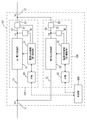
- FIG. 2 is a block diagram schematically illustrating the electrical configuration of the power conversion device of the first embodiment.
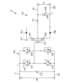
- FIG. 3 is a circuit diagram illustrating a specific configuration of a first power conversion unit in the power conversion device of the first embodiment.
- FIG. 4 is a circuit diagram illustrating a specific configuration of a second power conversion unit in the power conversion device of the first embodiment.
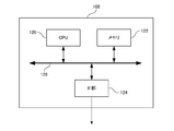
- FIG. 5 is a block diagram schematically illustrating the configuration of the control unit in the power conversion device of the first embodiment.
- FIG. 6 is a flowchart illustrating the flow of control performed by the control unit of the power conversion device of the first embodiment.
- a power conversion device that performs power conversion between a first conductive path and a second conductive path, a first power supply having a first power conversion unit that performs power conversion, and a second power source that performs power conversion.
- a second power source having a conversion unit and a control unit for controlling the first power source and the second power source are provided, and the control unit performs a predetermined normal operation on the first power source and the second power source.
- the first power supply and the second power supply are based on the normal control to be performed, the first cumulative information indicating the cumulative state of the operation of the first power supply, and the second cumulative information indicating the cumulative state of the operation of the second power supply.
- a power conversion device that performs corrective control and corrective control to correct the bias of the operation.
- the power conversion device of the above [1] has a first power supply and a second power supply based on the first cumulative information indicating the cumulative state of the operation of the first power supply and the second cumulative information indicating the cumulative state of the operation of the second power supply. It is possible to forcibly correct the bias of the operation of. Therefore, when the operations of the first power supply and the second power supply are biased, it is possible to prevent the load bias from being accumulated without being corrected.
- one of the first power supply and the second power supply is continuously or intermittently used until the bias between the operations of the first power supply and the second power supply reaches a predetermined correction state.
- the power conversion device of the above [2] forcibly causes a bias in operation by forcibly stopping one of the first power supply and the second power supply continuously or intermittently until a predetermined correction state is reached. And it can be corrected effectively.
- the first cumulative information includes the first change number, which is the number of times a predetermined state change has occurred in the first power source, and the second cumulative information includes the state change in the second power source.
- the power conversion device according to [1] or [2], wherein the control unit performs the corrective control based on the first change count and the second change count, including the second change count which is the number of occurrences. ..
- the power conversion device of the above [3] can perform corrective control based on the number of predetermined state changes in the first power supply and the second power supply. Therefore, this power conversion device can perform corrective control that reflects the bias in the number of times of the above state changes.
- the power conversion device of the above [3] performs corrective control so as to reduce the difference between the first change count and the second change count.
- This power conversion device can be corrected so as to equalize the number of times of the state change, and can suppress the bias of the load caused by the difference in the number of times of the state change becoming too large.
- the first change count includes the first start count, which is the start count of the first power supply
- the second change count includes the second start count, which is the start count of the second power supply.
- the power conversion device of the above [4] can perform corrective control so as to reduce the difference in the number of activations of the first power supply and the second power supply. Therefore, this power conversion device can suppress the bias of the load caused by the difference in the number of activations becoming too large.
- the number of times of the first change includes the number of times of the first temperature change, which is the number of times a predetermined temperature change occurs in the first power source, and the number of times of the second change is the number of times of the temperature change in the second power source.
- the power conversion device according to [3], wherein the control unit performs the corrective control based on the number of times of the first temperature change and the number of times of the second temperature change, including the number of times of the second temperature change, which is the number of times the above occurs. ..
- the power conversion device of the above [5] can perform corrective control based on a predetermined number of temperature changes in each of the first power supply and the second power supply. Therefore, this power conversion device can perform corrective control that reflects the bias in the number of temperature changes.
- the power conversion device of the above [5] performs corrective control so as to reduce the difference between the number of times of the first temperature change and the number of times of the second temperature change.
- This power conversion device can be corrected so as to equalize the number of temperature changes, and can suppress the bias of the load caused by the difference in the number of temperature changes becoming too large.
- the first cumulative information includes a first cumulative value which is a cumulative value of the output power amount in the first power supply, and the second cumulative information is a cumulative value of the output power amount in the second power supply.
- the power conversion device according to any one of [1] to [3], which includes a second cumulative value and the control unit performs the corrective control based on the first cumulative value and the second cumulative value. ..
- the power conversion device of the above [6] can perform corrective control based on the cumulative value of the output power amount of the first power supply and the cumulative value of the output power amount of the second power supply. Therefore, this power conversion device can perform corrective control that reflects the bias of the cumulative value of the output power amount.
- the power conversion device of the above [6] performs corrective control so as to reduce the difference between the first cumulative value and the second cumulative value.
- This power conversion device can be corrected so as to suppress the bias of the cumulative value of the output power amount, and can suppress the bias of the burden caused by the difference of the cumulative value of the output power amount becoming too large. ..
- the power conversion device of the above [7] can perform corrective control in a light load state where the output current is equal to or less than the threshold value, it becomes easy to solve or suppress the problem that the responsiveness is lowered by the corrective control.
- the power conversion device of the above [8] forcibly corrects the load bias in the first power supply and the second power supply connected in parallel while realizing a configuration in which the rated current of the second power supply can be relatively suppressed. be able to.
- the first power supply operates in a constant voltage mode in which the voltage of the first output path is controlled to the first target voltage, and the second power supply controls the current of the second output path to a current limit value.
- the second target voltage is set to be larger than the first target voltage, and the second target voltage is set to be larger than the first target voltage.
- the power conversion device of the above [9] can operate the first power supply in the constant voltage mode, and can operate the second power supply by switching between the constant voltage mode and the constant current mode.
- This power conversion device can operate the second power supply in the constant current mode when the output current is required to some extent and the current in the second output path is maintained at the current limit value.
- the second power supply can be operated in the constant voltage mode on condition that the value of the output current is greatly reduced and the current value of the second output path is lower than the current limit value.
- the power conversion device can perform these operations, and can forcibly correct the bias when the load is biased in the plurality of power conversion units due to these operations.
- the vehicle-mounted power supply system 100 can function as a vehicle-mounted DC voltage supply system mounted on a vehicle such as an electric vehicle.
- the power supply system 100 may supply a DC voltage to the load 110.
- the power supply system 100 includes a power conversion device 101 and a battery 102.
- the load 110 may be any electric device mounted on the vehicle, and may be, for example, an accessory device (cell motor, alternator, radiator cooling fan, etc.) necessary for operating the engine or motor.
- the type of load 110 is not limited, and may include an electric power steering system, an electric parking brake, lighting, a wiper drive unit, a navigation device, and the like.
- the battery 102 is a battery (for example, a secondary battery) that supplies a high voltage (for example, 300 V).
- the positive electrode terminal on the high potential side of the battery 102 is electrically connected to the first conductive path 11.
- the negative electrode terminal on the low potential side of the battery 102 is electrically connected to a ground (not shown).
- the power conversion device 101 mainly includes a first power supply 104, a second power supply 106, and a control unit 108.
- the first power source 104 and the second power source 106 are connected in parallel between the first conductive path 11 and the second conductive path 12, and as shown in FIG. 2, the first power conversion unit 21 and the second power conversion are performed.
- the portion 22 is connected in parallel between the first conductive path 11 and the second conductive path 12.
- the power conversion device 101 is a device that performs power conversion between the first conductive path 11 and the second conductive path 12.
- the power conversion device 101 steps down the input voltage input from the battery 102 via the first conductive path 11 and applies an output voltage lower than the voltage of the first conductive path 11 to the second conductive path 12. Can be done.
- voltage means a potential difference from a reference potential.
- the voltage of the first conductive path 11 means the potential difference between the first conductive path 11 and the reference potential
- the voltage of the second conductive path 12 means the potential difference between the second conductive path 12 and the reference potential.
- the conductive path that generates the reference potential on the first conductive path 11 side and the conductive path that generates the reference potential on the second conductive path 12 side are insulated.
- Both the first power supply 104 and the second power supply 106 function as DC-DC converters.
- the first power supply 104 and the second power supply 106 convert the DC voltage VH input from the battery 102 into predetermined output voltages V1 and V2, respectively, and output the DC voltage VH from their respective output terminals.
- the first power supply 104 includes a first power conversion unit 21 that performs power conversion, an in-power supply control unit 31 that drives the first power conversion unit 21, an interface unit 61, and a first voltage. It has a value detection unit 41 and a first current value detection unit 51.
- the in-power supply control unit 31 corresponds to an example of the first drive unit.
- the interface unit 61 is also referred to as an IF unit 61.
- the first power conversion unit 21 converts the electric power input from the first conductive path 11 via the first input path 71, and outputs the electric power to the second conductive path 12 via the first output path 81. conduct.
- the first input path 71 is a conductive path branched from the first conductive path 11, one end of which is electrically connected to the first conductive path 11 and the other end of which is electrically connected to the first power conversion unit 21. ..
- One end of the first output path 81 is electrically connected to the first power conversion unit 21, and the other end is electrically connected to the second conductive path 12.
- the first power conversion unit 21 is configured as, for example, a full-bridge type isolated DCDC converter as shown in FIG. In FIG. 3, the first voltage value detection unit 41, the first current value detection unit 51, and the like are omitted.
- the first power conversion unit 21 includes an input circuit unit 21X, a transformer unit 21Y, and an output circuit unit 21Z.
- the input circuit unit 21X includes a plurality of semiconductor switch elements 21A, 21B, 21C, 21D and a capacitor 21E, and is electrically connected to the primary coil 21F of the transformer unit 21Y.
- the input circuit unit 21X generates an AC voltage in the primary coil 21F according to the switching operation of the plurality of semiconductor switch elements 21A, 21B, 21C, 21D.
- the switching operation of the plurality of semiconductor switch elements 21A, 21B, 21C, and 21D is controlled by the in-power supply control unit 31, and specifically, CV (Constant Voltage) control described later is performed.
- the output circuit section 21Z includes diodes 21J and 21K, an inductor 21L, and a capacitor 21M, is electrically connected to the secondary coil 21G and 21H of the transformer section 21Y, and is an AC voltage applied to the secondary coil 21G and 21H. Is rectified and a DC voltage is output.
- the first power conversion unit 21 performs voltage conversion by switching operations of the semiconductor switch elements 21A, 21B, 21C, and 21D.
- the first power conversion unit 21 steps down the input voltage VH (potential difference between the first conductive path 11 and the conductive path 13A on the ground side) applied to the first conductive path 11 and outputs the voltage to the first output path 81.
- a voltage (potential difference between the first output path 81 and the ground-side conductive path 13B) is generated.
- the conductive paths 13A and 13B are reference conductive paths maintained at, for example, about 0 V.
- the temperature sensor 21P is arranged in the vicinity of the drive switch (semiconductor switch elements 21A, 21B, 21C, 21D) in the first power conversion unit 21, detects the temperature of the drive switch, and indicates the temperature Ta1 of the drive switch. Is input to the power supply in-power control unit 31.
- the temperature sensor 21Q is arranged in the vicinity of the capacitor 21M, detects the temperature of the capacitor 21M, and inputs a signal indicating the temperature Tb1 of the capacitor 21M to the power supply internal control unit 31.
- the temperature sensors 21P and 21Q may be omitted.
- the first current value detection unit 51 is interposed in the middle of the first output path 81.
- the first current value detection unit 51 detects the value of the current flowing through the first output path 81 (first current value I1), and inputs a signal indicating the first current value I1 to the in-power supply control unit 31.
- the first power conversion unit 21 performs a power conversion operation (specifically, a step-down operation)
- the first current value detection unit 51 outputs the output current output by the first power conversion unit 21 via the first output path 81. Is detected as the first current value I1.
- the first voltage value detection unit 41 detects the voltage value (first voltage value V1) of the first output path 81, and inputs a signal indicating the first voltage value V1 to the in-power supply control unit 31.
- the first voltage value detection unit 41 detects the value of the output voltage applied by the first power conversion unit 21 to the first output path 81 as the first voltage value V1. Then, a signal indicating this output voltage is input to the power supply internal control unit 31.
- the IF unit 61 receives the data transmitted from the control unit 108 and inputs it to the power supply in-power control unit 31. Further, the IF unit 61 can cooperate with the in-power supply control unit 31 to transmit the first current value I1, the first voltage value V1, and the temperatures Ta1 and Tb1 acquired by the in-power supply control unit 31 to the control unit 108.
- the in-power supply control unit 31 is configured as a control device having an information processing function, and is configured by, for example, a microcomputer including an internal memory.
- the internal memory stores a program to be executed by the in-power supply control unit 31 and necessary parameters.
- the in-power supply control unit 31 can control the first power conversion unit 21 based on the data received from the IF unit 61. For example, the in-power supply control unit 31 calculates a set value required for the operation of the first power conversion unit 21 and sets it in the first power conversion unit 21.
- control unit 108 operates so as to give a constant output voltage target value to the first power supply 104.
- the output voltage target value given to the first power supply 104 by the control unit 108 is also referred to as a “first target voltage”.
- the mode in which a constant target voltage is output by the above CV control is also referred to as a constant voltage mode.
- the first power supply 104 can perform a voltage conversion operation (step-down operation) so that the voltage of the first output path 81 becomes the first target voltage.
- the in-power supply control unit 31 drives the first power conversion unit 21 so as to output the first target voltage to the first output path 81.
- the first power conversion unit 21 operates in a constant voltage mode by being driven by the in-power supply control unit 31 (the above-mentioned CV control), steps down the DC voltage VH input from the battery 102, and sets the voltage of the first output path 81 to the above.
- the voltage conversion operation can be performed so as to be the first target voltage.
- the second power supply 106 includes a second power conversion unit 22 that performs power conversion, an in-power supply control unit 32 that drives the second power conversion unit 22, an interface unit 62, and a second voltage. It has a value detecting unit 42 and a second current value detecting unit 52.
- the in-power supply control unit 32 corresponds to an example of the second drive unit.
- the interface unit 62 is also referred to as an IF unit 62.
- the second power conversion unit 22 is connected in parallel to the first power conversion unit 21, converts the power input from the first conductive path 11 via the second input path 72, and forms the second output path 82.
- the operation of outputting electric power to the second conductive path 12 is performed.
- the second input path 72 is a conductive path branched from the first conductive path 11, one end of which is electrically connected to the first conductive path 11 and the other end of which is electrically connected to the second power conversion unit 22. ..
- One end of the second output path 82 is electrically connected to the second power conversion unit 22, and the other end is electrically connected to the second conductive path 12.
- the second power conversion unit 22 is configured as a full-bridge type isolated DCDC converter similar to the first power conversion unit 21 shown in FIG. In FIG. 4, the second voltage value detecting unit 42, the second current value detecting unit 52, and the like are not shown.
- the second power conversion unit 22 includes an input circuit unit 22X, a transformer unit 22Y, and an output circuit unit 22Z.
- the input circuit unit 22X includes a plurality of semiconductor switch elements 22A, 22B, 22C, 22D and a capacitor 22E, and is electrically connected to the primary coil 22F of the transformer unit 22Y.
- the input circuit unit 22X generates an AC voltage in the primary coil 22F according to the switching operation of the plurality of semiconductor switch elements 22A, 22B, 22C, 22D.
- the switching operation of the plurality of semiconductor switch elements 22A, 22B, 22C, and 22D is controlled by the in-power supply control unit 32, and specifically, CVCC (Constant Voltage Constant Curent) control is performed.
- the output circuit section 22Z includes diodes 22J and 22K, an inductor 22L, and a capacitor 22M, is electrically connected to the secondary coil 22G and 22H of the transformer section 22Y, and is an AC voltage applied to the secondary coil 22G and 22H. Is rectified and a DC voltage is output.
- the second power conversion unit 22 performs voltage conversion by switching operations of the semiconductor switch elements 22A, 22B, 22C, and 22D.
- the second power conversion unit 22 steps down the input voltage VH (potential difference between the first conductive path 11 and the conductive path 13C on the ground side) applied to the first conductive path 11 and outputs the voltage to the second output path 82.
- a voltage (potential difference between the second output path 82 and the ground-side conductive path 13D) is generated.
- the conductive paths 13C and 13D are reference conductive paths maintained at, for example, about 0 V.
- the temperature sensor 22P is arranged in the vicinity of the drive switch (semiconductor switch elements 22A, 22B, 22C, 22D) in the second power conversion unit 22, detects the temperature of the drive switch, and indicates the temperature Ta2 of the drive switch. Is input to the power supply in-power control unit 32.
- the temperature sensor 22Q is arranged in the vicinity of the capacitor 22M, detects the temperature of the capacitor 22M, and inputs a signal indicating the temperature Tb2 of the capacitor 22M to the power supply internal control unit 32.
- the second current value detection unit 52 is interposed in the middle of the second output path 82.
- the second current value detection unit 52 detects the value of the current flowing through the second output path 82 (second current value I2), and inputs a signal indicating the second current value I2 to the in-power supply control unit 32.
- the second power conversion unit 22 performs a power conversion operation (specifically, a step-down operation)
- the second current value detection unit 52 outputs the output current output by the second power conversion unit 22 via the second output path 82. Is detected as the second current value I2.
- the second voltage value detection unit 42 detects the voltage value (second voltage value V2) of the second output path 82, and inputs a signal indicating the second voltage value V2 to the in-power supply control unit 32.
- the second voltage value detection unit 42 detects the value of the output voltage applied by the second power conversion unit 22 to the second output path 82 as the second voltage value V2. Then, a signal indicating this output voltage is input to the power supply internal control unit 32.
- the IF unit 62 receives the data transmitted from the control unit 108 and inputs it to the power supply in-power control unit 32. Further, the IF unit 62 can cooperate with the in-power supply control unit 32 to transmit the second current value I2, the second voltage value V2, and the temperatures Ta2 and Tb2 acquired by the in-power supply control unit 32 to the control unit 108.
- the in-power supply control unit 32 is configured as a control device having an information processing function, and is configured by, for example, a microcomputer including an internal memory.
- the internal memory stores a program to be executed by the in-power supply control unit 32, necessary parameters, and the like.
- the in-power supply control unit 32 can control the second power conversion unit 22 based on the data received from the IF unit 62. For example, the power supply in-power control unit 32 calculates a set value required for the operation of the second power conversion unit 22 and sets it in the second power conversion unit 22.
- the control unit 108 operates so as to give a constant output voltage target value to the second power supply 106.
- the output voltage target value given to the second power supply 106 by the control unit 108 is also referred to as a “second target voltage”.
- the second target voltage is, for example, a value slightly higher than the first target voltage.
- the second target voltage may be directly supplied from the control unit 108 to the second power supply 106, the first target voltage is applied from the control unit 108 to the second power supply 106, and the second power supply 106 is higher than the first target voltage.
- the second target voltage may set a voltage that is a certain level higher.
- the control unit 108 operates so as to give a constant current limit value to the second power supply 106.
- the current limit value may be directly given from the control unit 108 to the second power supply 106, or the load current value is given from the control unit 108 to the second power supply 106, and the second power supply 106 is a current at a constant ratio of the load current value.
- the value may be a current limit value.
- the load current value is a current value supplied from the power supply system 100 to the load 110.
- the second power supply 106 operates by CVCC control based on the second target voltage and the current limit value.
- the second power supply 106 can also operate in a constant voltage mode that outputs a designated constant voltage (second target voltage) by the above-mentioned CV control. Further, the second power supply 106 can also operate so as to output a designated constant current value (the above current limit value) by CC (Constant Current) control.
- CC Constant Current
- the mode that outputs the specified constant current value is also referred to as the constant current mode. That is, the second power supply 106 can operate by switching between the operation in the constant voltage mode and the constant current mode.
- the second power conversion unit 22 operates in a constant voltage mode or a constant current mode by being driven by the power supply internal control unit 32 (the above-mentioned CVCC control).
- the second power conversion unit 22 When operating in the constant voltage mode, the second power conversion unit 22 performs a voltage conversion operation in which the DC voltage VH input from the battery 102 is stepped down and the voltage in the second output path 82 is set as the second target voltage.
- the second power conversion unit 22 When operating in the constant current mode, the second power conversion unit 22 performs a voltage conversion operation in which the DC voltage VH input from the battery 102 is stepped down and the current in the second output path 82 is set as the current limit value.
- the in-power supply control unit 32 operates the second power conversion unit 22 in the constant current mode when the second current value I2 is maintained at the current limit value.
- the in-power supply control unit 32 switches between the constant voltage mode and the constant current mode with the feedback calculation result when operating in the constant voltage mode and the constant current mode. It is performed based on the feedback calculation result when operating and the arbitration result of.
- the feedback calculation result when operating in the constant voltage mode is an operation amount calculated by performing a feedback calculation (for example, PI calculation or PID calculation) based on the deviation between the second target voltage and the second voltage value V2. be.
- This manipulated variable is an manipulated variable that attempts to bring the second voltage value V2 closer to the second target voltage.
- the feedback calculation result when operating in the constant current mode is an operation amount calculated by performing a feedback calculation (for example, PI calculation or PID calculation) based on the deviation between the current limit value and the second current value I2. ..
- This manipulated variable is an manipulated variable that attempts to bring the second current value I2 closer to the current limit value.
- the control unit 32 in the power supply periodically updates the operation amount (update of the duty), and when the above arbitration is performed, the change in the operation amount from the previous cycle (specifically, the change in duty). Adopt the mode in which the feedback calculation result is obtained.
- the control unit 108 includes a CPU (Central Processing Unit) 120, a memory 122, an interface unit (hereinafter referred to as an IF unit) 124, and a bus 126. Data transmission between each unit in the control unit 108 is performed via the bus 126.
- the memory 122 has one or more storage media, and includes, for example, a rewritable semiconductor non-volatile memory.
- the memory 122 stores a program executed by the CPU 120, predetermined parameters, and the like. A part of the memory 122 is used as a work area when the CPU 120 executes a program.
- the control unit 108 is, for example, an ECU (Electronic Control Unit) of an electric vehicle or the like.
- the CPU 120 has a function of controlling the operations of the first power source 104 and the second power source 106, controls the first power conversion unit 21 by giving an instruction to the first power source 104, and gives an instruction to the second power source 106. This controls the second power conversion unit 22. Specifically, the CPU 120 transmits the first target voltage to the first power supply 104 via the IF unit 124. Further, the CPU 120 transmits the first target voltage or the second target voltage, and the load current value or the current limit value to the second power supply 106 via the IF unit 124.
- the first power supply 104 can operate in the constant voltage mode based on the first target voltage, and operates so as to output a voltage equal to the first target voltage.
- the second power supply 106 operates to output a current equal to the current limit value when operating in the constant current mode, and operates to output a voltage equal to the second target voltage when operating in the constant voltage mode. ..
- the following description relates to power conversion control in the power supply system 100.
- the control of FIG. 6 is realized by the control unit 108 (specifically, the CPU 120) reading a predetermined program from the memory 122 and executing the program.
- the control unit 108 starts the control shown in FIG. 6 when a predetermined start condition is satisfied (for example, when the vehicle is in the starting state or when other start conditions are satisfied).
- the control unit 108 confirms the cumulative state of the operation of the first power supply 104 and the cumulative state of the operation of the second power supply 106 in step S20.
- the control unit 108 uses the cumulative value (first power amount) of the output power of the first power supply 104 as the first cumulative information indicating the cumulative state of the operation of the first power supply 104. Cumulative value) is adopted. Further, the control unit 108 adopts a cumulative value (second cumulative value) of the electric energy (second cumulative value) of the output power of the second power source 106 as the second cumulative information indicating the cumulative state of the operation of the second power source 106. .. Then, in step S21, the control unit 108 confirms the first cumulative value and the second cumulative value, and obtains the difference between the first cumulative value and the second cumulative value.
- the control unit 108 has a function of continuously acquiring the first cumulative value and the second cumulative value.
- the control unit 108 continuously acquires the first current value I1 and the first voltage value V1 from the first power supply 104, and the first by the first current value I1 and the first voltage value V1.
- a method of continuously calculating and updating the cumulative value (first cumulative value) of the output power amount of the power supply 104 may be used.
- the control unit 108 continuously acquires the second current value I2 and the second voltage value V2 from the second power source 106, and the second current value I2 and the second voltage value V2 are used to obtain the second cumulative value.
- a method of continuously calculating and updating the cumulative value (second cumulative value) of the output power amount of the power supply 106 may be used.
- each of the first power supply 104 and the second power supply 106 continuously calculates and updates the cumulative value of its own output power amount, and the first power supply 104 continuously transfers the latest first cumulative value to the control unit 108.
- the second power source 106 may output and continuously output the latest second cumulative value to the control unit 108.
- the control unit 108 determines whether or not the correction condition is satisfied in step S21.
- the correction condition is that "the difference between the first cumulative value and the second cumulative value is equal to or more than a certain value and the output current output to the second conductive path is equal to or less than the threshold value".
- the control unit 108 performs corrective control in step S22.
- the output current value IL is, for example, the sum of the first current value I1 and the second current value I2 at the time of performing step S21.
- the control unit 108 performs normal control in step S23.
- the control unit 108 performs normal control when the above correction conditions are not satisfied, and causes the first power supply 104 and the second power supply 106 to perform predetermined normal operations.
- the control unit 108 gives an operation permission command to the first power supply 104 and the second power supply 106, gives the first target voltage to the first power supply 104, and gives the second power supply 106 the operation permission command.
- information for setting the second target voltage and the current limit value is given.
- the first power supply 104 operates in a constant voltage mode based on the first target voltage when the above-mentioned normal control is performed.
- the second power supply 106 switches between operation in the constant voltage mode based on the second target voltage and operation in the constant current mode based on the current limit value.
- the control unit 108 performs correction control when the correction condition is satisfied, and shows the first cumulative information indicating the cumulative state of the operation of the first power supply 104 and the cumulative state of the operation of the second power supply 106. 2
- the bias of the operation of the first power supply 104 and the second power supply 106 is corrected based on the accumulated information.
- the control unit 108 prohibits the operation of the first power supply 104 when the first cumulative value is larger than the second cumulative value, and performs a normal operation only on the second power supply 106.
- the normal operation in this case is an operation performed by switching between the operation in the constant voltage mode based on the second target voltage and the operation in the constant current mode based on the current limit value.
- the control unit 108 prohibits the operation of the second power supply 106 when the second cumulative value is larger than the first cumulative value, and performs a normal operation only on the first power supply 104.
- the normal operation in this case is an operation in the constant voltage mode based on the first target voltage.
- the corrective control includes the forced stop control (prohibition of operation).
- the control unit 108 has one of the first power supply 104 and the second power supply 106 (specifically, the cumulative value) until the operation bias of the first power supply 104 and the second power supply 106 becomes a predetermined correction state. Forced stop control is performed so that the larger side) is continuously forcibly stopped.
- the correction state referred to here is until the correction condition is no longer satisfied in step S21, and specifically, a state in which the difference between the first cumulative value and the second cumulative value is less than a certain value is exemplified.
- step S22 or step S23 the control unit determines whether or not the end condition is satisfied in step S24, and if not, returns the process to step S20 and performs the process after step S20 again. ..
- the control unit 108 determines in step S24 that the end condition is satisfied, the control unit 108 performs end processing in step S25 to stop the operations of the first power supply 104 and the second power supply 106.
- the control unit 108 gives an operation stop command to the first power supply 104 and the second power supply 106.
- the power conversion device 101 has the first power supply 104 and the second power supply 106 based on the first cumulative information indicating the cumulative state of the operation of the first power supply 104 and the second cumulative information indicating the cumulative state of the operation of the second power supply 106. It is possible to forcibly correct the bias of the operation of. Therefore, when the operations of the first power supply 104 and the second power supply 106 are biased, it is possible to prevent the load bias from being accumulated without being corrected.
- the power conversion device 101 forcibly and effectively causes a bias in operation by continuously or intermittently forcibly stopping one of the first power supply 104 and the second power supply 106 until a predetermined correction state is reached. Can be corrected.
- the power conversion device 101 can perform corrective control based on the cumulative value of the output power amount of the first power supply 104 and the cumulative value of the output power amount of the second power supply 106. Therefore, the power conversion device 101 can perform corrective control that reflects the bias of the cumulative value of the output power amount. Specifically, the power conversion device 101 performs corrective control so as to reduce the difference between the first cumulative value and the second cumulative value. Therefore, the power conversion device 101 can be corrected so as to suppress the bias of the cumulative value of the output power amount, and suppress the bias of the burden caused by the difference of the cumulative value of the output power amount becoming too large. Can be done.
- the power conversion device 101 can perform corrective control in a light load state where the output current is equal to or less than the threshold value, it becomes easy to solve or suppress the problem that the responsiveness is lowered by the corrective control.
- the power conversion device 101 can operate the first power supply 104 in the constant voltage mode, and can operate the second power supply 106 by switching between the constant voltage mode and the constant current mode.
- the power conversion device 101 can operate the second power supply 106 in the constant current mode when the output current is required to some extent and the current in the second output path 82 is maintained at the current limit value.
- the power conversion device 101 can operate the second power supply 106 in the constant voltage mode on condition that the value of the output current is greatly reduced and the current value of the second output path 82 is lower than the current limit value. ..
- the power conversion device 101 can perform these operations, and can forcibly correct the bias when the load is biased in the plurality of power conversion units due to these operations.
- the power conversion device 101 of the second embodiment is different from the power conversion device 101 of the first embodiment only in the content of the control of FIG. 6, and is the same as the power conversion device 101 of the first embodiment except for the content of the control of FIG. Is.
- the power conversion device 101 of the second embodiment has the configurations of FIGS. 1 to 5 like the power conversion device 101 of the first embodiment. Therefore, FIGS. 1 to 5 are also referred to in the description of the power conversion device 101 of the second embodiment.
- the power conversion device 101 of the second embodiment differs from the power conversion device 101 of the first embodiment only in the processing of S20, S21, and S22 in the control of FIG. The processing of is the same as that of the power conversion device 101 of the first embodiment.
- the power conversion device 101 of the second embodiment has a function of counting the number of activations of the first power supply 104 and a function of counting the number of activations of the second power supply 106, in addition to the configuration of the first embodiment.
- the method of counting the number of activations of the first power supply 104 and the second power supply 106 may be a method of counting the number of times that the control unit 108 gives an operation instruction to each of the first power supply 104 and the second power supply 106. ..
- each of the first power supply 104 and the second power supply 106 counts its own activation number, and each of the first power supply 104 and the second power supply 106 determines its own activation number of times. It may be a method of sending to.
- the control unit 108 confirms the number of times the first power supply 104 is started and the number of times the second power supply 106 is started when the process of step S20 is performed. Then, the control unit 108 determines whether or not the correction condition is satisfied in step S21.
- the corrective condition in this case is "the difference between the number of times the first power supply 104 is started and the number of times the second power source 106 is started is equal to or greater than a certain value, and the value IL of the output current output to the second conductive path 12 is equal to or less than the threshold value. That. "
- the control unit 108 When the difference between the number of times the first power supply 104 is started and the number of times the second power source 106 is started is equal to or more than a certain value and the value IL of the output current output to the second conductive path 12 is equal to or less than the threshold value, the control unit 108 is used. Performs corrective control in step S22.
- the corrective control in step S22 is the same as the corrective control in step S22 in the first embodiment, but the operation with the larger number of activations is prohibited and the operation with the smaller number of activations is allowed.
- the control unit 108 prohibits the operation of the first power supply 104 when the number of times the first power supply 104 is started is larger than the number of times the second power supply 106 is started, and the second power supply 106.
- the normal operation in this case is an operation performed by switching between the operation in the constant voltage mode based on the second target voltage and the operation in the constant current mode based on the current limit value.
- the control unit 108 prohibits the operation of the second power supply 106 when the number of times the second power supply 106 is started is larger than the number of times the first power supply 104 is started, and the control unit 108 prohibits the operation of the first power supply 104.
- the normal operation in this case is an operation in the constant voltage mode based on the first target voltage.
- step S23 When the difference between the number of times the first power supply 104 is started and the number of times the second power source 106 is started is less than a certain value, or when the value IL of the output current output to the second conductive path 12 exceeds the threshold value, the control unit 108 Is normally controlled in step S23.
- the normal control of step S23 in this case is the same as the normal control of step S23 in the first embodiment.
- the processing of steps S24 and S25 is the same as that of steps S24 and S25 of the first embodiment, respectively.
- the power conversion device 101 of the second embodiment includes the first change number of times, which is the number of times a predetermined state change occurs in the first power supply 104 as the first cumulative information.
- the power conversion device 101 includes, as the second cumulative information, the number of times of the second change, which is the number of times the state change has occurred in the second power supply.
- the control unit 108 performs corrective control based on the first change count and the second change count.
- the power conversion device 101 can perform corrective control based on a predetermined number of state changes in the first power supply 104 and the second power supply 106. Therefore, the power conversion device 101 can perform corrective control that reflects the bias in the number of times of the state change.
- the first change count includes the first boot count, which is the boot count of the first power supply 104.
- the second change count includes the second boot count, which is the boot count of the second power supply 106.
- the control unit 108 performs corrective control so as to reduce the difference between the first activation number and the second activation number based on the first activation number and the second activation number.
- the power conversion device 101 can suppress the bias of the load caused by the difference in the number of activations becoming too large.
- the power conversion device 101 of the third embodiment is different from the power conversion device 101 of the first embodiment only in the content of the control of FIG. 6, and is the same as the power conversion device 101 of the first embodiment except for the content of the control of FIG. Is.
- the power conversion device 101 of the third embodiment has the configurations of FIGS. 1 to 5 like the power conversion device 101 of the first embodiment. Therefore, FIGS. 1 to 5 are also referred to in the description of the power conversion device 101 of the third embodiment.
- the power conversion device 101 of the third embodiment is different from the power conversion device 101 of the first embodiment only in the processing of S20, S21, and S22 in the control of FIG. The process of is the same as that of the power conversion device 101 of the first embodiment.
- the power conversion device 101 of the third embodiment has a function of counting the number of times a predetermined temperature change occurs in the first power supply 104, and the temperature change in the second power supply 106. It has a function of counting the number of times it has occurred.
- the method of counting the temperature change in the first power source 104 and the second power source 106 is a method of counting the temperature change based on the temperatures Ta1 and Ta2 acquired by the control unit 108 from the first power source 104 and the second power source 106. Can be adopted.
- the temperature change can be, for example, "a change in which the temperature at a predetermined position rises from the first threshold value to the second threshold value and then falls from the second threshold value to the first threshold value".
- the "change in which the temperature of the drive switch of the power conversion unit rises from the first threshold value to the second threshold value and then falls from the second threshold value to the first threshold value” is the above-mentioned temperature change.
- the temperature change in the first power source 104 is "a change in which the temperature Ta1 rises from the first threshold value to the second threshold value and then falls from the second threshold value to the first threshold value".
- the control unit 108 or the first power supply 104 counts the temperature change in the first power supply 104, and the control unit 108 continuously acquires the value.
- the temperature change in the second power source 106 is "a change in which the temperature Ta2 rises from the first threshold value to the second threshold value and then falls from the second threshold value to the first threshold value".
- the control unit 108 or the second power source 106 counts the temperature change in the second power source 106, and the control unit 108 continuously acquires the value.
- the control unit 108 when the process of step S20 is performed, the control unit 108 confirms the temperature change in the first power supply 104 and the temperature change in the second power supply 106. Then, the control unit 108 determines whether or not the correction condition is satisfied in step S21.
- the corrective condition in this case is "the difference between the number of times the temperature changes in the first power supply 104 and the number of times the temperature changes in the second power supply 106 is equal to or more than a certain value, and the output current output to the second conductive path 12 The value IL of is less than or equal to the threshold value.
- the difference between the number of times the temperature changes in the first power supply 104 (the number of times the temperature changes first) and the number of times the temperature changes in the second power source 106 (the number of times the temperature changes second) is equal to or greater than a certain value and is second. 2
- corrective control is performed in step S22.
- the corrective control in step S22 is the same as the corrective control in step S22 in the first embodiment, but the operation with the larger number of temperature changes is stopped and the operation with the smaller number of temperature changes is allowed.
- the operation of the first power supply 104 is performed when the number of temperature changes in the first power supply 104 is larger than the number of times of the temperature change in the second power supply 106. Is prohibited, and only the second power source 106 is allowed to perform normal operation.
- the normal operation in this case is an operation performed by switching between the operation in the constant voltage mode based on the second target voltage and the operation in the constant current mode based on the current limit value.
- the control unit 108 performs corrective control in step S22
- the operation of the second power supply 106 is performed when the number of temperature changes in the second power supply 106 is larger than the number of times of the temperature change in the first power supply 104. Is prohibited, and only the first power supply 104 is allowed to perform normal operation.
- the normal operation in this case is an operation in the constant voltage mode based on the first target voltage.
- the control unit 108 When the difference between the number of times of the temperature change in the first power supply 104 and the number of times of the above temperature change in the second power supply 106 is less than a certain value, the control unit 108 performs normal control in step S23.
- the control unit 108 performs normal control in step S23 even when the value IL of the output current output to the second conductive path 12 exceeds the threshold value.
- the normal control of step S23 in this case is the same as the normal control of step S23 in the first embodiment.
- the processing of steps S24 and S25 is the same as that of steps S24 and S25 of the first embodiment, respectively.
- the power conversion device 101 of the third embodiment includes, as the first cumulative information, the number of first changes, which is the number of times a predetermined state change has occurred in the first power supply 104. Then, the second cumulative information includes the number of times of the second change, which is the number of times the state change has occurred in the second power source 106. Then, the control unit 108 performs corrective control based on the first change count and the second change count. Further, in the power conversion device 101 of the third embodiment, the first change count includes the first temperature change count, which is the number of times a predetermined temperature change occurs in the first power supply 104. The second change count includes the second temperature change count, which is the number of times the temperature change occurs in the second power supply 106.
- the temperature change is a change in which the temperature of the drive switch rises from the first threshold value to the second threshold value and then falls from the second threshold value to the first threshold value.
- the control unit 108 performs corrective control based on the number of first temperature changes and the number of second temperature changes so as to reduce the difference between the number of first temperature changes and the number of second temperature changes. Therefore, the power conversion device 101 can be corrected so as to equalize the number of times of the temperature change, and can suppress the bias of the burden caused by the difference in the number of times of the temperature change becoming too large.
- the output current output to the second conductive path is equal to or less than the threshold value
- the threshold value is included as one of the correction conditions, but such a condition may not be present.
- the normal control is a control in which the first power supply 104 is operated in the constant voltage mode and the second power supply 106 is operated in the constant voltage mode or the constant current mode, but the control is not limited to this example.
- the normal control may be a control in which the first power supply 104 is operated in the constant voltage mode and the second power supply 106 is operated in the constant voltage mode, or the first power supply 104 is operated in the constant voltage mode and the second power supply 106 is operated. May be controlled to operate in a constant current mode.
- the normal control may be a control in which the first power supply 104 is switched and operated in the constant voltage mode or the constant current mode, and the second power supply 106 is switched and operated in the constant voltage mode or the constant current mode.
- the normal control may include a plurality of normal controls. For example, a control in which the above-mentioned plurality of normal controls are selectively performed according to a state may be adopted in the power conversion device.
- the case where the bias exceeding a certain level occurs is “the case where the correction condition is satisfied", but the present invention is not limited to this example.
- it may be "when the correction condition is satisfied” that a certain time or more has passed since the previous correction control.
- the case where the process of step S21 is performed first after the vehicle is started may be “when the corrective condition is satisfied”.
- the other "predetermined time has arrived” may be "when the corrective conditions are met”.
- the end condition of the corrective control in the control of FIG. 6 (condition for returning to the normal control) is "the above-mentioned corrective condition is no longer satisfied", but instead of the above-mentioned corrective condition,
- the end condition of the corrective control may be that a certain period of time has passed from the start of the corrective control.
- the corrective control is continuously performed while the corrective condition is satisfied, but the power conversion device may intermittently perform the corrective control while the corrective condition is satisfied.
- the correction control may be performed every time the first power supply 104 and the second power supply 106 are started up a predetermined number of times.
- the power conversion device may alternately perform the correction control for a certain period of time and the normal control for a predetermined time or longer while the correction condition is satisfied.
- the power conversion device may perform corrective control for a certain period of time or corrective control until the end condition is satisfied every time a predetermined timing is reached, while the corrective condition is satisfied.
- the first change count may be the number of times the power fluctuation of a certain value or more occurs in the first power supply (first fluctuation count).
- the second change count may be the number of times the power fluctuation of a certain value or more occurs in the second power supply (second fluctuation count).
- corrective control may be performed so as to reduce the difference between the first fluctuation number and the second fluctuation number based on the first fluctuation number and the second fluctuation number.
- the control unit 108 forcibly stops the first power supply 104 and allows the operation of the second power supply 106.
- Corrective control may be performed.
- the control unit 108 forcibly stops the second power supply 106 and performs corrective control so as to allow the operation of the first power supply 104. Just do it.
- the power conversion device is a device including the control unit 108, but a device such as the control unit 108 that does not include control may be a power conversion device.
- a device such as the control unit 108 that does not include control may be a power conversion device.
- the portion of the power conversion device 101 excluding the control unit 108 may be the power conversion device.
- the isolated DCDC converter as shown in FIGS. 3 and 4 is exemplified as a specific configuration of the first power conversion unit 21 and the second power conversion unit 22, but the configurations other than those shown in FIGS. DCDC converter may be used.
- the power supply system 100 is mounted on a vehicle such as an electric vehicle, but the present invention is not limited to this.
- the power supply system 100 may be mounted on a vehicle of a type other than these, for example, a PHEV (Plug-in Hybrid Electric Vehicle) or a HEV (Hybrid Electric Vehicle), or may be mounted on a device other than the vehicle.
- a PHEV Plug-in Hybrid Electric Vehicle
- HEV Hybrid Electric Vehicle
Landscapes
- Engineering & Computer Science (AREA)
- Power Engineering (AREA)
- Dc-Dc Converters (AREA)
- Charge And Discharge Circuits For Batteries Or The Like (AREA)
- Electric Propulsion And Braking For Vehicles (AREA)
Abstract
電力変換装置(101)において、制御部(108)は、第1電源(104)及び第2電源(106)に予め定められた通常動作を行わせる通常制御を行い得る。制御部(108)は、第1電源(104)と第2電源(106)の動作の偏りを是正する是正制御も行い得る。制御部(108)は、第1電源(104)の動作の累積状態を示す第1累積情報と第2電源(106)の動作の累積状態を示す第2累積情報とに基づいて是正制御を行う。
Description
本開示は、電力変換装置に関する。
電気自動車等においては、高電圧バッテリ(例えば、直流300V)の電圧をDC-DCコンバータにより低電圧(例えば、直流14V)に変換して負荷に供給する技術が採用されている。この種の電力変換装置では、電力供給先の負荷の必要電流が大きい場合、1つのDC-DCコンバータでは電流容量が不足してしまうことがある。その対策として、例えば、複数のDC-DCコンバータを並列接続して使用することが考えられる。
特許文献1には、複数のDC-DCコンバータを並列接続してなる直流電圧変換装置が開示されている。この直流電圧変換装置は、マスタ側のDCDCコンバータの出力電圧がスレーブ側の出力電圧よりも高く設定され、負荷消費電流平均値のほぼ半分の電流値であり最大許容電流値よりも小さい電流値が電流制限値として設定される。特許文献1の技術は、この構成により、並列接続されるDCDCコンバータの各寿命の均等化を図ることを目的としている。
特許文献1の技術は、負荷消費電流常用範囲のα-β以上α+β以下の範囲で2つのDC-DCコンバータの負荷が均等化されやすい構成を採用することで、直流電圧変換装置の長寿命化を図ろうとするものである。しかし、特許文献1の技術は、何らかの事情によって2つのDC-DCコンバータにおいて負担が偏った場合に、その偏りを強制的に是正することができない。
本開示は、複数の電力変換部が並列に接続された電力変換装置において、複数の電力変換部における負担の偏りを強制的に是正することを目的の一つとする。
本開示の一つである電力変換装置は、
第1導電路と第2導電路との間で電力変換を行う電力変換装置であって、
電力変換を行う第1電力変換部を有する第1電源と、
電力変換を行う第2電力変換部を有する第2電源と、
前記第1電源及び前記第2電源を制御する制御部と、
を備え、
前記制御部は、前記第1電源及び前記第2電源に予め定められた通常動作を行わせる通常制御と、前記第1電源の動作の累積状態を示す第1累積情報と前記第2電源の動作の累積状態を示す第2累積情報とに基づいて前記第1電源と前記第2電源の動作の偏りを是正する是正制御と、を行う。
第1導電路と第2導電路との間で電力変換を行う電力変換装置であって、
電力変換を行う第1電力変換部を有する第1電源と、
電力変換を行う第2電力変換部を有する第2電源と、
前記第1電源及び前記第2電源を制御する制御部と、
を備え、
前記制御部は、前記第1電源及び前記第2電源に予め定められた通常動作を行わせる通常制御と、前記第1電源の動作の累積状態を示す第1累積情報と前記第2電源の動作の累積状態を示す第2累積情報とに基づいて前記第1電源と前記第2電源の動作の偏りを是正する是正制御と、を行う。
本開示の一つである電力変換装置は、並列に接続された複数の電力変換部における負担の偏りを強制的に是正することができる。
以下では、本開示の実施形態が列記されて例示される。なお、以下で例示される〔1〕~〔9〕の特徴は、矛盾しない範囲でどのように組み合わされてもよい。
〔1〕第1導電路と第2導電路との間で電力変換を行う電力変換装置であって、電力変換を行う第1電力変換部を有する第1電源と、電力変換を行う第2電力変換部を有する第2電源と、前記第1電源及び前記第2電源を制御する制御部と、を備え、前記制御部は、前記第1電源及び前記第2電源に予め定められた通常動作を行わせる通常制御と、前記第1電源の動作の累積状態を示す第1累積情報と前記第2電源の動作の累積状態を示す第2累積情報とに基づいて前記第1電源と前記第2電源の動作の偏りを是正する是正制御と、を行う電力変換装置。
上記〔1〕の電力変換装置は、第1電源の動作の累積状態を示す第1累積情報と第2電源の動作の累積状態を示す第2累積情報とに基づいて第1電源と第2電源の動作の偏りを強制的に是正することができる。よって、第1電源と第2電源の動作が偏った場合に負担の偏りが是正されずに累積することを抑えることができる。
〔2〕前記是正制御は、前記第1電源と前記第2電源の動作の偏りが予め定められた是正状態となるまで前記第1電源及び前記第2電源のうちの一方を連続的又は断続的に強制停止させる強制停止制御を含む〔1〕に記載の電力変換装置。
上記〔2〕の電力変換装置は、第1電源及び第2電源のうちの一方を予め定められた是正状態となるまで連続的又は断続的に強制停止させることで、動作の偏りを強制的に且つ効果的に是正することができる。
〔3〕前記第1累積情報は、前記第1電源において予め定められた状態変化が生じた回数である第1変化回数を含み、前記第2累積情報は、前記第2電源において前記状態変化が生じた回数である第2変化回数を含み、前記制御部は、前記第1変化回数と前記第2変化回数とに基づいて前記是正制御を行う〔1〕又は〔2〕に記載の電力変換装置。
上記〔3〕の電力変換装置は、第1電源及び第2電源における予め定められた状態変化の回数に基づいて是正制御を行うことができる。よって、この電力変換装置は、上記状態変化の回数の偏りを反映した是正制御が可能となる。
上記〔3〕の電力変換装置は、上記第1変化回数と上記第2変化回数との差を小さくするように是正制御を行うことが望ましい。この電力変換装置は、上記状態変化の回数を均等化するように是正することができ、上記状態変化の回数の差が大きくなりすぎることに起因する負担の偏りを抑えることができる。
〔4〕前記第1変化回数は、前記第1電源の起動回数である第1起動回数を含み、前記第2変化回数は、前記第2電源の起動回数である第2起動回数を含み、前記制御部は、前記第1起動回数と前記第2起動回数とに基づいて前記第1起動回数と前記第2起動回数の差を小さくするように前記是正制御を行う〔3〕に記載の電力変換装置。
上記〔4〕の電力変換装置は、第1電源及び第2電源のそれぞれの起動回数の差を小さくするように是正制御を行うことができる。よって、この電力変換装置は、起動回数の差が大きくなりすぎることに起因する負担の偏りを抑えることができる。
〔5〕前記第1変化回数は、前記第1電源において予め定められた温度変化が生じた回数である第1温度変化回数を含み、前記第2変化回数は、前記第2電源において前記温度変化が生じた回数である第2温度変化回数を含み、前記制御部は、前記第1温度変化回数と前記第2温度変化回数とに基づいて前記是正制御を行う〔3〕に記載の電力変換装置。
上記〔5〕の電力変換装置は、第1電源及び第2電源のそれぞれにおける予め定められた温度変化の回数に基づいて是正制御を行うことができる。よって、この電力変換装置は、上記温度変化の回数の偏りを反映した是正制御が可能となる。
上記〔5〕の電力変換装置は、上記第1温度変化回数と上記第2温度変化回数との差を小さくするように是正制御を行うことが望ましい。この電力変換装置は、上記温度変化の回数を均等化するように是正することができ、上記温度変化の回数の差が大きくなりすぎることに起因する負担の偏りを抑えることができる。
〔6〕前記第1累積情報は、前記第1電源における出力電力量の累積値である第1累積値を含み、前記第2累積情報は、前記第2電源における出力電力量の累積値である第2累積値を含み、前記制御部は、前記第1累積値と前記第2累積値とに基づいて前記是正制御を行う〔1〕から〔3〕のいずれか一つに記載の電力変換装置。
上記〔6〕の電力変換装置は、第1電源における出力電力量の累積値と第2電源における出力電力量の累積値とに基づいて是正制御を行うことができる。よって、この電力変換装置は、出力電力量の累積値の偏りを反映した是正制御が可能となる。
上記〔6〕の電力変換装置は、上記第1累積値と上記第2累積値との差を小さくするように是正制御を行うことが望ましい。この電力変換装置は、上記出力電力量の累積値の偏りを抑えるように是正することができ、上記出力電力量の累積値の差が大きくなりすぎることに起因する負担の偏りを抑えることができる。
〔7〕前記制御部は、前記第2導電路に出力される出力電流が閾値以下である場合に前記是正制御を行う〔1〕から〔6〕のいずれか一つに記載の電力変換装置。
上記〔7〕の電力変換装置は、出力電流が閾値以下である軽負荷状態において是正制御を行うことができるため、是正制御によって応答性が低下する問題を解消又は抑制しやすくなる。
〔8〕前記第1電源の定格電流よりも前記第2電源の定格電流のほうが小さい〔1〕から〔7〕のいずれか一つに記載の電力変換装置。
上記〔8〕の電力変換装置は、第2電源の定格電流を相対的に抑え得る構成を実現しつつ、並列に接続された第1電源及び第2電源における負担の偏りを強制的に是正することができる。
〔9〕前記第1電源は、前記第1出力路の電圧を第1目標電圧に制御する定電圧モードで動作し、前記第2電源は、前記第2出力路の電流を電流制限値に制御する定電流モードと前記第2出力路の電圧を第2目標電圧に制御する定電圧モードとに切り替わる構成をなし、前記第2目標電圧が前記第1目標電圧よりも大きく設定され、前記第2出力路の電流が前記電流制限値である場合に定電流モードが維持され、前記第2出力路の電流が前記電流制限値を下回ることを条件として定電圧モードに切り替わる〔1〕から〔8〕のいずれか一つに記載の電力変換装置。
上記〔9〕の電力変換装置は、第1電源を定電圧モードで動作させることができ、第2電源を定電圧モードと定電流モードとに切り替えて動作させることができる。この電力変換装置は、出力電流がある程度要求されて第2出力路の電流が電流制限値で維持される場合には、第2電源を定電流モードで動作させることができる。一方で、この電力変換装置は、出力電流の値が大きく低下して第2出力路の電流値が電流制限値を下回ることを条件として、第2電源を定電圧モードで動作させ得る。電力変換装置は、これらの動作を行うことを可能としつつ、これらの動作に起因して複数の電力変換部において負担の偏りが生じる場合の偏りを強制的に是正することができる。
<第1実施形態>
1.全体構成
図1で示される第1実施形態に係る車載用の電源システム100は、例えば電気自動車等の車両に搭載される車載用の直流電圧供給システムとして機能し得る。電源システム100は、負荷110に直流電圧を供給し得る。電源システム100は、電力変換装置101とバッテリ102とを備える。
1.全体構成
図1で示される第1実施形態に係る車載用の電源システム100は、例えば電気自動車等の車両に搭載される車載用の直流電圧供給システムとして機能し得る。電源システム100は、負荷110に直流電圧を供給し得る。電源システム100は、電力変換装置101とバッテリ102とを備える。
負荷110は、車両に搭載される電気機器であればよく、例えば、エンジンやモータを稼動するのに必要な付属機器(セルモータ、オルタネータ及びラジエータクーリングファン等)であってもよい。負荷110の種類は限定されず、電動パワーステアリングシステム、電動パーキングブレーキ、照明、ワイパー駆動部、ナビゲーション装置等を含んでいてもよい。
バッテリ102は、高電圧(例えば300V)を供給するバッテリ(例えば2次電池)である。バッテリ102における高電位側の正極端子は、第1導電路11に電気的に接続されている。バッテリ102における低電位側の負極端子は、図示されていないグラウンドに電気的に接続されている。
電力変換装置101は、主に、第1電源104と第2電源106と制御部108とを備える。第1電源104及び第2電源106は、第1導電路11と第2導電路12との間に並列に接続されており、図2のように、第1電力変換部21と第2電力変換部22とが第1導電路11と第2導電路12との間に並列に接続されている。電力変換装置101は、第1導電路11と第2導電路12との間で電力変換を行う装置である。電力変換装置101は、バッテリ102から第1導電路11を介して入力される入力電圧を降圧し、第2導電路12に対して第1導電路11の電圧よりも低い出力電圧を印加する動作を行い得る。
なお、本明細書において、特別な説明が無い限り、電圧とは基準電位との電位差を意味する。例えば、第1導電路11の電圧は、第1導電路11と基準電位との電位差を意味し、第2導電路12の電圧は、第2導電路12と基準電位との電位差を意味する。なお、以下の代表例では、第1導電路11側の基準電位を生じさせる導電路と第2導電路12側の基準電位を生じさせる導電路は絶縁されている。
第1電源104及び第2電源106は、いずれもDC-DCコンバータとして機能する。第1電源104及び第2電源106はそれぞれ、バッテリ102から入力される直流電圧VHを所定の出力電圧V1及びV2にそれぞれ変換して、各々の出力端子から出力する。
図2に示されるように、第1電源104は、電力変換を行う第1電力変換部21と、第1電力変換部21を駆動する電源内制御部31と、インタフェース部61と、第1電圧値検出部41と、第1電流値検出部51と、を有する。電源内制御部31は、第1駆動部の一例に相当する。以下の説明では、インタフェース部61は、IF部61とも称される。
第1電力変換部21は、第1導電路11から第1入力路71を介して入力される電力を変換し、第1出力路81を介して第2導電路12に電力を出力する動作を行う。第1入力路71は、第1導電路11から分岐した導電路であり、一端が第1導電路11に電気的に接続され、他端が第1電力変換部21に電気的に接続される。第1出力路81は、一端が第1電力変換部21に電気的に接続され、他端が第2導電路12に電気的に接続される。
第1電力変換部21は、例えば、図3のようなフルブリッジ方式の絶縁型のDCDCコンバータとして構成されている。図3では、第1電圧値検出部41や第1電流値検出部51などは省略されている。第1電力変換部21は、入力回路部21X、トランス部21Y、出力回路部21Zを有する。入力回路部21Xは、複数の半導体スイッチ素子21A,21B,21C,21Dと、コンデンサ21Eとを備え、トランス部21Yの一次側コイル21Fに電気的に接続される。入力回路部21Xは、複数の半導体スイッチ素子21A,21B,21C,21Dのスイッチング動作に応じて一次側コイル21Fに交流電圧を生じさせる。複数の半導体スイッチ素子21A,21B,21C,21Dのスイッチング動作の制御は電源内制御部31によって行われ、具体的には後述のCV(Constant Voltage)制御が行われる。出力回路部21Zは、ダイオード21J,21K、インダクタ21L、コンデンサ21Mを備え、トランス部21Yの二次側コイル21G,21Hに電気的に接続され、二次側コイル21G,21Hに印加される交流電圧を整流して直流電圧を出力する。第1電力変換部21は、半導体スイッチ素子21A,21B,21C,21Dのスイッチング動作によって電圧変換を行う。第1電力変換部21は、第1導電路11に印加された入力電圧VH(第1導電路11とグラウンド側の導電路13Aとの間の電位差)を降圧し、第1出力路81に出力電圧(第1出力路81とグラウンド側の導電路13Bとの間の電位差)を生じさせる。導電路13A,13Bは、例えば0V程度に維持される基準導電路である。
温度センサ21Pは、第1電力変換部21における駆動スイッチ(半導体スイッチ素子21A,21B,21C,21D)の近傍に配置され、この駆動スイッチの温度を検出し、この駆動スイッチの温度Ta1を示す信号を電源内制御部31に入力する。温度センサ21Qは、コンデンサ21Mの近傍に配置され、コンデンサ21Mの温度を検出し、コンデンサ21Mの温度Tb1を示す信号を電源内制御部31に入力する。温度センサ21P,21Qは、省略されてもよい。
図2のように、第1電流値検出部51は、第1出力路81の途中に介在する。第1電流値検出部51は、第1出力路81を流れる電流の値(第1電流値I1)を検出し、第1電流値I1を示す信号を電源内制御部31に入力する。第1電力変換部21が電力変換動作(具体的には降圧動作)を行う場合、第1電流値検出部51は、第1電力変換部21が第1出力路81を介して出力する出力電流の値を第1電流値I1として検出する。
第1電圧値検出部41は、第1出力路81の電圧値(第1電圧値V1)を検出し、電源内制御部31に第1電圧値V1を示す信号を入力する。第1電力変換部21が電力変換動作を行う場合、第1電圧値検出部41は、第1電力変換部21が第1出力路81に印加する出力電圧の値を第1電圧値V1として検出し、この出力電圧を示す信号を電源内制御部31に入力する。
IF部61は、制御部108から伝送されるデータを受信し、電源内制御部31に入力する。更に、IF部61は、電源内制御部31と協働し、電源内制御部31が取得した第1電流値I1、第1電圧値V1、温度Ta1,Tb1を制御部108に送信し得る。
電源内制御部31は、情報処理機能を有する制御装置として構成され、例えば、内部メモリを含むマイクロコンピュータによって構成されている。内部メモリには、電源内制御部31が実行すべきプログラム及び必要なパラメータ等が記憶されている。電源内制御部31は、IF部61から受信したデータに基づき、第1電力変換部21を制御し得る。例えば、電源内制御部31は、第1電力変換部21の動作に必要な設定値を算出し、第1電力変換部21に設定する。
本構成では、制御部108は、第1電源104に対して一定の出力電圧目標値を与えるように動作する。以下の説明では、制御部108が第1電源104に与える出力電圧目標値は「第1目標電圧」とも称される。また、以下の説明では、上記のCV制御によって一定の目標電圧を出力するモードは、定電圧モードとも称される。
第1電源104は、制御部108から上記第1目標電圧が与えられた場合、第1出力路81の電圧を上記第1目標電圧とするように電圧変換動作(降圧動作)を行い得る。具体的には、電源内制御部31は、第1出力路81に上記第1目標電圧を出力させるように第1電力変換部21を駆動する。第1電力変換部21は、電源内制御部31による駆動(上記CV制御)によって定電圧モードで動作し、バッテリ102から入力される直流電圧VHを降圧し、第1出力路81の電圧を上記第1目標電圧とするように電圧変換動作を行い得る。
図2に示されるように、第2電源106は、電力変換を行う第2電力変換部22と、第2電力変換部22を駆動する電源内制御部32と、インタフェース部62と、第2電圧値検出部42と、第2電流値検出部52と、を有する。電源内制御部32は、第2駆動部の一例に相当する。以下の説明では、インタフェース部62は、IF部62とも称される。
第2電力変換部22は、第1電力変換部21に対して並列に接続され、第1導電路11から第2入力路72を介して入力される電力を変換し、第2出力路82を介して第2導電路12に電力を出力する動作を行う。第2入力路72は、第1導電路11から分岐した導電路であり、一端が第1導電路11に電気的に接続され、他端が第2電力変換部22に電気的に接続される。第2出力路82は、一端が第2電力変換部22に電気的に接続され、他端が第2導電路12に電気的に接続される。
図4で示されるように、第2電力変換部22は、図3で示される第1電力変換部21と同様のフルブリッジ方式の絶縁型のDCDCコンバータとして構成されている。図4では、第2電圧値検出部42や第2電流値検出部52などは図示が省略されている。第2電力変換部22は、入力回路部22X、トランス部22Y、出力回路部22Zを有する。入力回路部22Xは、複数の半導体スイッチ素子22A,22B,22C,22Dと、コンデンサ22Eとを備え、トランス部22Yの一次側コイル22Fに電気的に接続される。入力回路部22Xは、複数の半導体スイッチ素子22A,22B,22C,22Dのスイッチング動作に応じて一次側コイル22Fに交流電圧を生じさせる。複数の半導体スイッチ素子22A,22B,22C,22Dのスイッチング動作の制御は電源内制御部32によって行われ、具体的にはCVCC(Constant Voltage Constant Current)制御が行われる。出力回路部22Zは、ダイオード22J,22K、インダクタ22L、コンデンサ22Mを備え、トランス部22Yの二次側コイル22G,22Hに電気的に接続され、二次側コイル22G,22Hに印加される交流電圧を整流して直流電圧を出力する。第2電力変換部22は、半導体スイッチ素子22A,22B,22C,22Dのスイッチング動作によって電圧変換を行う。第2電力変換部22は、第1導電路11に印加された入力電圧VH(第1導電路11とグラウンド側の導電路13Cとの間の電位差)を降圧し、第2出力路82に出力電圧(第2出力路82とグラウンド側の導電路13Dとの間の電位差)を生じさせる。導電路13C,13Dは、例えば0V程度に維持される基準導電路である。
温度センサ22Pは、第2電力変換部22における駆動スイッチ(半導体スイッチ素子22A,22B,22C,22D)の近傍に配置され、この駆動スイッチの温度を検出し、この駆動スイッチの温度Ta2を示す信号を電源内制御部32に入力する。温度センサ22Qは、コンデンサ22Mの近傍に配置され、コンデンサ22Mの温度を検出し、コンデンサ22Mの温度Tb2を示す信号を電源内制御部32に入力する。
図2のように、第2電流値検出部52は、第2出力路82の途中に介在する。第2電流値検出部52は、第2出力路82を流れる電流の値(第2電流値I2)を検出し、第2電流値I2を示す信号を電源内制御部32に入力する。第2電力変換部22が電力変換動作(具体的には降圧動作)を行う場合、第2電流値検出部52は、第2電力変換部22が第2出力路82を介して出力する出力電流の値を第2電流値I2として検出する。
第2電圧値検出部42は、第2出力路82の電圧値(第2電圧値V2)を検出し、電源内制御部32に第2電圧値V2を示す信号を入力する。第2電力変換部22が電力変換動作を行う場合、第2電圧値検出部42は、第2電力変換部22が第2出力路82に印加する出力電圧の値を第2電圧値V2として検出し、この出力電圧を示す信号を電源内制御部32に入力する。
IF部62は、制御部108から伝送されるデータを受信し、電源内制御部32に入力する。更に、IF部62は、電源内制御部32と協働し、電源内制御部32が取得した第2電流値I2、第2電圧値V2、温度Ta2,Tb2を制御部108に送信し得る。
電源内制御部32は、情報処理機能を有する制御装置として構成され、例えば、内部メモリを含むマイクロコンピュータによって構成されている。内部メモリには、電源内制御部32が実行すべきプログラム及び必要なパラメータ等が記憶されている。電源内制御部32は、IF部62から受信したデータに基づき、第2電力変換部22を制御し得る。例えば、電源内制御部32は、第2電力変換部22の動作に必要な設定値を算出し、第2電力変換部22に設定する。
本構成では、制御部108は、第2電源106に対して一定の出力電圧目標値を与えるように動作する。以下の説明では、制御部108が第2電源106に与える出力電圧目標値は「第2目標電圧」とも称される。第2目標電圧は、例えば、第1目標電圧よりも少し高い値とされる。第2目標電圧は、制御部108から第2電源106に直接与えられてもよく、制御部108から第2電源106に第1目標電圧が与えられ、第2電源106が第1目標電圧よりも一定レベル高い電圧を第2目標電圧が設定してもよい。更に、制御部108は、第2電源106に対して一定の電流制限値を与えるように動作する。電流制限値は、制御部108から第2電源106に直接与えられてもよく、制御部108から第2電源106に負荷電流値が与えられ、第2電源106が負荷電流値の一定割合の電流値を電流制限値としてもよい。負荷電流値は、電源システム100から負荷110に供給する電流値である。
第2電源106は、上記第2目標電圧及び上記電流制限値に基づき、CVCC制御により動作する。第2電源106は、上述のCV制御により、指定された一定電圧(第2目標電圧)を出力する定電圧モードでも動作することができる。また、第2電源106は、CC(Constant Current)制御により、指定された一定電流値(上記電流制限値)を出力するように動作することもできる。以下の説明では、指定された一定電流値を出力するモードは定電流モードとも称される。つまり、第2電源106は、定電圧モードでの動作と定電流モードとを切り替えて動作し得る。
第2電力変換部22は、電源内制御部32による駆動(上記CVCC制御)によって定電圧モード又は定電流モードで動作する。第2電力変換部22は、定電圧モードで動作する場合、バッテリ102から入力される直流電圧VHを降圧し、第2出力路82の電圧を上記第2目標電圧とする電圧変換動作を行う。第2電力変換部22は、定電流モードで動作する場合、バッテリ102から入力される直流電圧VHを降圧し、第2出力路82の電流を上記電流制限値とする電圧変換動作を行う。電源内制御部32は、第2電流値I2が電流制限値で維持される場合、第2電力変換部22を定電流モードで動作させる。電源内制御部32は、第2電流値I2が電流制限値よりも小さい場合、定電圧モードと定電流モードとの切り替えを、定電圧モードで動作する場合のフィードバック演算結果と、定電流モードで動作する場合のフィードバック演算結果と、の調停結果に基づいて行う。定電圧モードで動作する場合のフィードバック演算結果は、第2目標電圧と第2電圧値V2との偏差に基づいてフィードバック演算(例えば、PI演算又はPID演算)を行うことで算出される操作量である。この操作量は、第2電圧値V2を第2目標電圧に近づけようとする操作量である。定電流モードで動作する場合のフィードバック演算結果は、電流制限値と第2電流値I2との偏差に基づいてフィードバック演算(例えば、PI演算又はPID演算)を行うことで算出される操作量である。この操作量は、第2電流値I2を電流制限値に近づけようとする操作量である。電源内制御部32は、操作量の更新(デューティの更新)を周期的に行い、上記の調停を行う場合には、先回の周期からの操作量の変化(具体的にはデューティの変化)がより小さくなるフィードバック演算結果が得られたモードを採用する。
図5に示されるように、制御部108は、CPU(Central Processing Unit)120、メモリ122、インタフェース部(以下、IF部という)124及びバス126を含む。制御部108における各部の間のデータ伝送は、バス126を介して行われる。メモリ122は、1以上の記憶媒体を有し、例えば、書換可能な半導体不揮発性メモリ等を含む。メモリ122には、CPU120が実行するプログラム及び所定のパラメータ等が記憶されている。メモリ122の一部の領域は、CPU120がプログラムを実行するときにワークエリアとして使用される。制御部108は、例えば、電気自動車等のECU(Electronic Control Unit)である。
CPU120は、第1電源104及び第2電源106の動作を制御する機能を有し、第1電源104に指示を与えることで第1電力変換部21を制御し、第2電源106に指示を与えることで第2電力変換部22を制御する。具体的には、CPU120は、IF部124を介して第1電源104に対して、第1目標電圧を伝送する。また、CPU120は、IF部124を介して第2電源106に対して、第1目標電圧又は第2目標電圧、及び、負荷電流値又は電流制限値を伝送する。第1電源104は、上記第1目標電圧に基づいて定電圧モードで動作しうるようになっており、第1目標電圧に等しい電圧を出力するように動作する。第2電源106は、定電流モードで動作するときには上記電流制限値に等しい電流を出力するように動作し、定電圧モードで動作するときには上記第2目標電圧に等しい電圧を出力するように動作する。
2.電力変換制御
次の説明は、電源システム100における電力変換制御に関する。
図6の制御は、制御部108(具体的にはCPU120)が、所定のプログラムをメモリ122から読出して実行することにより実現される。制御部108は、所定の開始条件が成立した場合(例えば、車両が始動状態となった場合、又はその他の開始条件が成立した場合)に図6で示される制御を開始する。
次の説明は、電源システム100における電力変換制御に関する。
図6の制御は、制御部108(具体的にはCPU120)が、所定のプログラムをメモリ122から読出して実行することにより実現される。制御部108は、所定の開始条件が成立した場合(例えば、車両が始動状態となった場合、又はその他の開始条件が成立した場合)に図6で示される制御を開始する。
制御部108は、図6の制御を開始した後、ステップS20において第1電源104の動作の累積状態と第2電源106の動作の累積状態とを確認する。以下の説明の例では、制御部108は、第1電源104の動作の累積状態を示す第1累積情報として第1電源104の出力電力の電力量(第1電力量)の累積値(第1累積値)を採用する。また、制御部108は、第2電源106の動作の累積状態を示す第2累積情報として第2電源106出力電力の電力量(第2電力量)の累積値(第2累積値)を採用する。そして、制御部108は、ステップS21において、上記第1累積値と上記第2累積値とを確認し、第1累積値と第2累積値との差を求める。
制御部108は、上記第1累積値及び上記第2累積値を継続的に取得する機能を有する。第1累積値の取得方法は、制御部108が第1電源104から第1電流値I1及び第1電圧値V1を継続的に取得し、第1電流値I1及び第1電圧値V1によって第1電源104の出力電力量の累積値(第1累積値)を継続的に算出・更新する方法であってもよい。第2累積値の取得方法は、制御部108が第2電源106から第2電流値I2及び第2電圧値V2を継続的に取得し、第2電流値I2及び第2電圧値V2によって第2電源106の出力電力量の累積値(第2累積値)を継続的に算出・更新する方法であってもよい。或いは、第1電源104及び第2電源106の各々が自身の出力電力量の累積値を継続的に算出・更新し、第1電源104が最新の第1累積値を制御部108に継続的に出力し、第2電源106が最新の第2累積値を制御部108に継続的に出力する構成でもよい。
制御部108は、ステップS20の後、ステップS21において是正条件が成立したか否かを判定する。是正条件は、「第1累積値と第2累積値との差が一定値以上となり且つ第2導電路に出力される出力電流が閾値以下であること」である。制御部108は、第1累積値と第2累積値との差が一定値以上であり出力電流の値ILが閾値以下である場合にはステップS22において是正制御を行う。出力電流の値ILは、例えば、ステップS21を行う時点での第1電流値I1と第2電流値I2との和である。制御部108は、第1累積値と第2累積値との差が一定値未満又は出力電流の値ILが閾値より大きい場合にはステップS23において通常制御を行う。
このように制御部108は、上記是正条件が成立していない場合には通常制御を行い、第1電源104及び前記第2電源106に予め定められた通常動作を行わせる。制御部108は、ステップS23において通常制御を行う場合、第1電源104及び第2電源106に動作許可指令を与え、第1電源104に対して上記第1目標電圧を与え、第2電源106に対して第2目標電圧及び電流制限値を設定するための情報を与える。第1電源104は、上記通常制御が行われる場合、第1目標電圧に基づいて定電圧モードで動作する。第2電源106は、上記通常制御が行われる場合、第2目標電圧に基づく定電圧モードでの動作と電流制限値に基づく定電流モードでの動作とを切り替えて行う。
一方、制御部108は、是正条件が成立している場合には是正制御を行い、第1電源104の動作の累積状態を示す第1累積情報と第2電源106の動作の累積状態を示す第2累積情報とに基づいて第1電源104と第2電源106の動作の偏りを是正する。制御部108は、ステップS22において是正制御を行う場合、第1累積値のほうが第2累積値よりも大きい場合には第1電源104の動作を禁止し、第2電源106のみに通常動作を行わせる。この場合の通常動作は、第2目標電圧に基づく定電圧モードでの動作と電流制限値に基づく定電流モードでの動作とを切り替えて行う動作である。制御部108は、ステップS22において是正制御を行う場合、第2累積値のほうが第1累積値よりも大きい場合には第2電源106の動作を禁止し、第1電源104のみに通常動作を行わせる。この場合の通常動作は、第1目標電圧に基づく定電圧モードでの動作である。
このように、図6の制御では、是正制御は強制停止制御(動作の禁止)を含んでいる。制御部108は、第1電源104と第2電源106の動作の偏りが予め定められた是正状態となるまで第1電源104及び第2電源106のうちの一方(具体的には、累積値が大きい側)を連続的に強制停止させるように強制停止制御を行う。ここでいう是正状態は、ステップS21において是正条件が成立しなくなるまでであり、具体的には、第1累積値と第2累積値との差が一定値未満となった状態が例示される。
制御部は、ステップS22又はステップS23の後、ステップS24において終了条件が成立したか否かを判定し、成立していない場合には、処理をステップS20に戻し、ステップS20以降の処理を再び行う。制御部108は、ステップS24において終了条件が成立したと判定した場合には、ステップS25において終了処理を行い、第1電源104及び第2電源106の動作を停止させる。終了処理では、例えば、制御部108が、第1電源104及び第2電源106に対して動作停止指令を与える。
本開示の効果の例示は、以下の通りである。
電力変換装置101は、第1電源104の動作の累積状態を示す第1累積情報と第2電源106の動作の累積状態を示す第2累積情報とに基づいて第1電源104と第2電源106の動作の偏りを強制的に是正することができる。よって、第1電源104と第2電源106の動作が偏った場合に負担の偏りが是正されずに累積することを抑えることができる。
電力変換装置101は、第1電源104の動作の累積状態を示す第1累積情報と第2電源106の動作の累積状態を示す第2累積情報とに基づいて第1電源104と第2電源106の動作の偏りを強制的に是正することができる。よって、第1電源104と第2電源106の動作が偏った場合に負担の偏りが是正されずに累積することを抑えることができる。
電力変換装置101は、第1電源104及び第2電源106のうちの一方を予め定められた是正状態となるまで連続的又は断続的に強制停止させることで、動作の偏りを強制的に且つ効果的に是正することができる。
電力変換装置101は、第1電源104における出力電力量の累積値と第2電源106における出力電力量の累積値とに基づいて是正制御を行うことができる。よって、この電力変換装置101は、出力電力量の累積値の偏りを反映した是正制御が可能となる。具体的には、電力変換装置101は、上記第1累積値と上記第2累積値との差を小さくするように是正制御を行う。よって、この電力変換装置101は、出力電力量の累積値の偏りを抑えるように是正することができ、上記出力電力量の累積値の差が大きくなりすぎることに起因する負担の偏りを抑えることができる。
電力変換装置101は、出力電流が閾値以下である軽負荷状態において是正制御を行うことができるため、是正制御によって応答性が低下する問題を解消又は抑制しやすくなる。
電力変換装置101は、第1電源104を定電圧モードで動作させることができ、第2電源106を定電圧モードと定電流モードとに切り替えて動作させることができる。この電力変換装置101は、出力電流がある程度要求されて第2出力路82の電流が電流制限値で維持される場合には、第2電源106を定電流モードで動作させることができる。一方で、この電力変換装置101は、出力電流の値が大きく低下して第2出力路82の電流値が電流制限値を下回ることを条件として、第2電源106を定電圧モードで動作させ得る。電力変換装置101は、これらの動作を行うことを可能としつつ、これらの動作に起因して複数の電力変換部において負担の偏りが生じる場合の偏りを強制的に是正することができる。
<第2実施形態>
第2実施形態の電力変換装置101は、図6の制御の内容のみが第1実施形態の電力変換装置101と異なり、図6の制御の内容以外は第1実施形態の電力変換装置101と同一である。例えば、第2実施形態の電力変換装置101は、第1実施形態の電力変換装置101と同様に図1~図5の構成を有する。よって、第2実施形態の電力変換装置101の説明でも、図1~図5が参照される。また、第2実施形態の電力変換装置101は、図6の制御のうちのS20、S21、S22の処理のみが第1実施形態の電力変換装置101と異なり、図6の制御のうちのそれ以外の処理は、第1実施形態の電力変換装置101と同一である。
第2実施形態の電力変換装置101は、図6の制御の内容のみが第1実施形態の電力変換装置101と異なり、図6の制御の内容以外は第1実施形態の電力変換装置101と同一である。例えば、第2実施形態の電力変換装置101は、第1実施形態の電力変換装置101と同様に図1~図5の構成を有する。よって、第2実施形態の電力変換装置101の説明でも、図1~図5が参照される。また、第2実施形態の電力変換装置101は、図6の制御のうちのS20、S21、S22の処理のみが第1実施形態の電力変換装置101と異なり、図6の制御のうちのそれ以外の処理は、第1実施形態の電力変換装置101と同一である。
第2実施形態の電力変換装置101は、第1実施形態の構成に加え、第1電源104の起動回数をカウントする機能と、第2電源106の起動回数をカウントする機能とを有する。第1電源104及び第2電源106の起動回数をカウントする方法は、制御部108が第1電源104及び第2電源106のそれぞれに動作指示を与えた回数をそれぞれカウントする方法であってもよい。或いは、各起動回数のカウント方法は、第1電源104及び第2電源106の各々が自身の起動回数をカウントし、第1電源104及び第2電源106の各々が自身の起動回数を制御部108に送信する方法であってもよい。
第2実施形態の電力変換装置101では、制御部108は、ステップS20の処理を行う場合、第1電源104の起動回数と第2電源106の起動回数とを確認する。そして、制御部108は、ステップS21において是正条件が成立したか否かを判定する。この場合の是正条件は、「第1電源104の起動回数と第2電源106の起動回数の差が一定値以上となり且つ第2導電路12に出力される出力電流の値ILが閾値以下であること」である。
制御部108は、第1電源104の起動回数と第2電源106の起動回数の差が一定値以上であり且つ第2導電路12に出力される出力電流の値ILが閾値以下である場合には、ステップS22において是正制御を行う。この場合のステップS22の是正制御は第1実施形態におけるステップS22の是正制御と同様であるが、起動回数の多い方の動作を禁止し、少ない方の動作を許容する。制御部108は、ステップS22において是正制御を行う場合、第1電源104の起動回数のほうが第2電源106の起動回数よりも大きい場合には第1電源104の動作を禁止し、第2電源106のみに通常動作を行わせる。この場合の通常動作は、第2目標電圧に基づく定電圧モードでの動作と電流制限値に基づく定電流モードでの動作とを切り替えて行う動作である。制御部108は、ステップS22において是正制御を行う場合、第2電源106の起動回数のほうが第1電源104の起動回数よりも大きい場合には第2電源106の動作を禁止し、第1電源104のみに通常動作を行わせる。この場合の通常動作は、第1目標電圧に基づく定電圧モードでの動作である。
制御部108は、第1電源104の起動回数と第2電源106の起動回数の差が一定値未満である場合、又は第2導電路12に出力される出力電流の値ILが閾値を超える場合には、ステップS23において通常制御を行う。この場合のステップS23の通常制御は第1実施形態におけるステップS23の通常制御と同様である。なお、第2実施形態の電力変換装置101では、ステップS24、S25の処理は、第1実施形態におけるステップS24、S25のそれぞれと同様である。
第2実施形態の電力変換装置101は、第1累積情報として第1電源104において予め定められた状態変化が生じた回数である第1変化回数を含む。そして、この電力変換装置101は、第2累積情報として第2電源において状態変化が生じた回数である第2変化回数を含む。そして、制御部108は、第1変化回数と第2変化回数とに基づいて是正制御を行う。この電力変換装置101は、第1電源104及び第2電源106における予め定められた状態変化の回数に基づいて是正制御を行うことができる。よって、この電力変換装置101は、上記状態変化の回数の偏りを反映した是正制御が可能となる。
具体的には、第1変化回数は、第1電源104の起動回数である第1起動回数を含む。そして、第2変化回数は、第2電源106の起動回数である第2起動回数を含む。そして、制御部108は、第1起動回数と第2起動回数とに基づいて第1起動回数と第2起動回数の差を小さくするように是正制御を行う。この電力変換装置101は、起動回数の差が大きくなりすぎることに起因する負担の偏りを抑えることができる。
<第3実施形態>
第3実施形態の電力変換装置101は、図6の制御の内容のみが第1実施形態の電力変換装置101と異なり、図6の制御の内容以外は第1実施形態の電力変換装置101と同一である。例えば、第3実施形態の電力変換装置101は、第1実施形態の電力変換装置101と同様に図1~図5の構成を有する。よって、第3実施形態の電力変換装置101の説明でも、図1~図5が参照される。また、第3実施形態の電力変換装置101は、図6の制御のうちのS20、S21、S22の処理のみが第1実施形態の電力変換装置101と異なり、図6の制御のうちのそれ以外の処理は第1実施形態の電力変換装置101と同一である。
第3実施形態の電力変換装置101は、図6の制御の内容のみが第1実施形態の電力変換装置101と異なり、図6の制御の内容以外は第1実施形態の電力変換装置101と同一である。例えば、第3実施形態の電力変換装置101は、第1実施形態の電力変換装置101と同様に図1~図5の構成を有する。よって、第3実施形態の電力変換装置101の説明でも、図1~図5が参照される。また、第3実施形態の電力変換装置101は、図6の制御のうちのS20、S21、S22の処理のみが第1実施形態の電力変換装置101と異なり、図6の制御のうちのそれ以外の処理は第1実施形態の電力変換装置101と同一である。
第3実施形態の電力変換装置101は、第1実施形態の構成に加え、第1電源104において予め定められた温度変化が生じた回数をカウントする機能と、第2電源106において上記温度変化が生じた回数をカウントする機能とを有する。第1電源104及び第2電源106での上記温度変化をカウントする方法は、制御部108が第1電源104及び第2電源106から取得する温度Ta1,Ta2に基づいて上記温度変化をカウントする方法を採用することができる。なお、第1電源104及び第2電源106の各々が自身における上記温度変化をカウントし、第1電源104及び第2電源106の各々が自身の上記温度変化の回数を制御部108に送信する方法であってもよい。
上記温度変化は、例えば、「所定位置の温度が第1閾値から第2閾値まで上昇した後、第2閾値から第1閾値まで下降した変化」とすることができる。以下の説明では、「電力変換部の駆動スイッチの温度が第1閾値から第2閾値まで上昇した後、第2閾値から第1閾値まで下降した変化」が上記温度変化である。第1電源104での上記温度変化は、「温度Ta1が第1閾値から第2閾値まで上昇した後、第2閾値から第1閾値まで下降した変化」である。制御部108又は第1電源104は、このような第1電源104での上記温度変化をカウントし、制御部108はその値を継続的に取得し続ける。また、第2電源106での上記温度変化は、「温度Ta2が第1閾値から第2閾値まで上昇した後、第2閾値から第1閾値まで下降した変化」である。制御部108又は第2電源106は、このような第2電源106での上記温度変化をカウントし、制御部108はその値を継続的に取得し続ける。
第3実施形態の電力変換装置101では、制御部108は、ステップS20の処理を行う場合、第1電源104での上記温度変化と第2電源106での上記温度変化とを確認する。そして、制御部108は、ステップS21において是正条件が成立したか否かを判定する。この場合の是正条件は、「第1電源104での上記温度変化の回数と第2電源106での上記温度変化の回数の差が一定値以上となり且つ第2導電路12に出力される出力電流の値ILが閾値以下であること」である。
制御部108は、第1電源104での上記温度変化の回数(第1温度変化回数)と第2電源106での上記温度変化の回数(第2温度変化回数)の差が一定値以上且つ第2導電路12の出力電流値ILが閾値以下である場合には、ステップS22にて是正制御を行う。この場合のステップS22の是正制御は第1実施形態におけるステップS22の是正制御と同様であるが、上記温度変化の回数の多い方の動作を停止させ、少ない方の動作を許容する。制御部108は、ステップS22において是正制御を行う場合、第1電源104での上記温度変化の回数のほうが第2電源106での上記温度変化の回数よりも大きい場合には第1電源104の動作を禁止し、第2電源106のみに通常動作を行わせる。この場合の通常動作は、第2目標電圧に基づく定電圧モードでの動作と電流制限値に基づく定電流モードでの動作とを切り替えて行う動作である。制御部108は、ステップS22において是正制御を行う場合、第2電源106での上記温度変化の回数のほうが第1電源104での上記温度変化の回数よりも大きい場合には第2電源106の動作を禁止し、第1電源104のみに通常動作を行わせる。この場合の通常動作は、第1目標電圧に基づく定電圧モードでの動作である。
制御部108は、第1電源104での上記温度変化の回数と第2電源106での上記温度変化の回数の差が一定値未満である場合、ステップS23において通常制御を行う。制御部108は、第2導電路12に出力される出力電流の値ILが閾値を超える場合にもステップS23において通常制御を行う。この場合のステップS23の通常制御は第1実施形態におけるステップS23の通常制御と同様である。なお、第3実施形態の電力変換装置101では、ステップS24、S25の処理は、第1実施形態におけるステップS24、S25のそれぞれと同様である。
第3実施形態の電力変換装置101は、第1累積情報として第1電源104において予め定められた状態変化が生じた回数である第1変化回数を含む。そして、第2累積情報として第2電源106において状態変化が生じた回数である第2変化回数を含む。そして、制御部108は、第1変化回数と第2変化回数とに基づいて是正制御を行う。更に、第3実施形態の電力変換装置101では、第1変化回数は、第1電源104において予め定められた温度変化が生じた回数である第1温度変化回数を含む。第2変化回数は、第2電源106において上記温度変化が生じた回数である第2温度変化回数を含む。上記温度変化は、駆動スイッチの温度が第1閾値から第2閾値まで上昇した後、第2閾値から第1閾値まで下降する変化である。制御部108は、第1温度変化回数と第2温度変化回数とに基づき、第1温度変化回数と第2温度変化回数との差を小さくするように是正制御を行う。よって、この電力変換装置101は、上記温度変化の回数を均等化するように是正することができ、上記温度変化の回数の差が大きくなりすぎることに起因する負担の偏りを抑えることができる。
<他の実施形態>
本開示は、上記記述及び図面によって説明した実施形態に限定されるものではない。例えば、上述又は後述の実施形態の特徴は、矛盾しない範囲であらゆる組み合わせが可能である。また、上述又は後述の実施形態のいずれの特徴も、必須のものとして明示されていなければ省略することもできる。更に、上述した実施形態は、次のように変更されてもよい。
本開示は、上記記述及び図面によって説明した実施形態に限定されるものではない。例えば、上述又は後述の実施形態の特徴は、矛盾しない範囲であらゆる組み合わせが可能である。また、上述又は後述の実施形態のいずれの特徴も、必須のものとして明示されていなければ省略することもできる。更に、上述した実施形態は、次のように変更されてもよい。
上記実施形態では、是正条件のうちの一つの条件として「第2導電路に出力される出力電流が閾値以下であること」が含まれていたが、このような条件が無くてもよい。
上記実施形態では、通常制御は、第1電源104を定電圧モードで動作させ、第2電源106を定電圧モード又は定電流モードで切り替えて動作させる制御であったが、この例に限定されない。通常制御は、第1電源104を定電圧モードで動作させ、第2電源106を定電圧モードで動作させる制御であってもよく、第1電源104を定電圧モードで動作させ、第2電源106を定電流モードで動作させる制御であってもよい。或いは、通常制御は、第1電源104を定電圧モード又は定電流モードで切り替えて動作させ、第2電源106を定電圧モード又は定電流モードで切り替えて動作させる制御であってもよい。また、通常制御は、複数の通常制御を含んでいてもよい。例えば、上述の複数の通常制御が、状態に応じて択一的に行われるような制御が電力変換装置に採用されてもよい。
上記実施形態では、一定レベルを超える偏りが生じた場合が「是正条件が成立した場合」であったが、この例に限定されない。例えば、前回の是正制御から一定時間以上経過したことが「是正条件が成立した場合」であってもよい。或いは、車両が始動した後に最初にステップS21の処理が行われる場合が「是正条件が成立した場合」であってもよい。或いは、その他の「予め定められた時期が到来したこと」が「是正条件が成立した場合」であってもよい。
上記実施形態では、図6の制御における是正制御の終了条件(通常制御に復帰する条件)は、「上述の是正条件が成立しなくなったこと」であったが、上述の是正条件に代えて、是正制御の開始から一定期間が経過したことを是正制御の終了条件としてもよい。
上記実施形態は、是正条件が成立している間は継続的に是正制御を行うが、電力変換装置は、是正条件が成立している間、断続的に是正制御を行ってもよい。例えば是正条件が成立している間は、第1電源104及び第2電源106を所定回数起動する毎に、是正制御を行ってもよい。或いは、電力変換装置は、是正条件が成立している間は、一定時間の是正制御と、所定時間以上の通常制御とを交互に行うようにしてもよい。或いは、電力変換装置は、是正条件が成立している間は、所定のタイミングが到来する毎に一定期間の是正制御又は終了条件が成立するまでの是正制御を行ってもよい。
上記実施形態において、図3、図4のコンデンサ21M,22Mがアルミ電解コンデンサである場合、コンデンサ21M,22Mのそれぞれの寿命を、「L=L0×2(105-Tc)/10」の推定寿命計算式に基づいて計算してもよい。この計算は、温度センサ21Q,22Qが検出する温度Tb1,Tb2に基づいて行うことができる。この式では、Lは、推定寿命計算値であり、L0は、コンデンサの保証寿命値(予め定められた固定値)であり、Tcは、各コンデンサの温度(例えば、温度Tb1,Tb2)である。そして、ステップS20、S21では、コンデンサ21M,22Mの推定寿命に偏りがあるか否かを判定し、偏りがある場合には、偏りを是正するように是正制御を行ってもよい。
第1変化回数は、第1電源において一定値以上の電力変動が生じた回数(第1変動回数)であってもよい。そして、第2変化回数は、第2電源において一定値以上の電力変動が生じた回数(第2変動回数)であってもよい。この場合、第1変動回数と第2変動回数とに基づいて第1変動回数と第2変動回数との差を小さくするように是正制御が行われればよい。具体的には、例えば、第1変動回数のほうが第2変動回数よりも一定値以上多い場合、制御部108は、第1電源104を強制停止させ、第2電源106の動作を許容するように是正制御を行えばよい。逆に、第2変動回数のほうが第1変動回数よりも一定値以上多い場合、制御部108は、第2電源106を強制停止させ、第1電源104の動作を許容するように是正制御を行えばよい。
上記実施形態では、電力変換装置が上記制御部108を含む装置であったが、上記制御部108のような制御を含まない装置が電力変換装置とされてもよい。例えば、電力変換装置101から上記制御部108を除いた部分が電力変換装置とされてもよい。
上記実施形態では、第1電力変換部21及び第2電力変換部22の具体的構成として、図3、図4のような絶縁型DCDCコンバータが例示されたが、図3、図4の構成以外のDCDCコンバータが用いられてもよい。
上記実施形態では、電源システム100が電気自動車などの車両に搭載されるが、これに限定されない。電源システム100は、これら以外の種類の車両、例えば、PHEV(Plug-in Hybrid Electric Vehicle)、HEV(Hybrid Electric Vehicle)に搭載されてもよく、車両以外の装置に搭載されてもよい。
なお、今回開示された実施の形態は全ての点で例示であって制限的なものではないと考えられるべきである。本発明の範囲は、今回開示された実施の形態に限定されるものではなく、特許請求の範囲によって示された範囲内又は特許請求の範囲と均等の範囲内での全ての変更が含まれることが意図される。
11 :第1導電路
12 :第2導電路
13A :導電路
13B :導電路
13C :導電路
13D :導電路
21 :第1電力変換部
21A :半導体スイッチ素子
21B :半導体スイッチ素子
21C :半導体スイッチ素子
21D :半導体スイッチ素子
21E :コンデンサ
21F :一次側コイル
21G :二次側コイル
21H :二次側コイル
21J :ダイオード
21K :ダイオード
21L :インダクタ
21M :コンデンサ
21P :温度センサ
21Q :温度センサ
21X :入力回路部
21Y :トランス部
21Z :出力回路部
22 :第2電力変換部
22A :半導体スイッチ素子
22B :半導体スイッチ素子
22C :半導体スイッチ素子
22D :半導体スイッチ素子
22E :コンデンサ
22F :一次側コイル
22G :二次側コイル
22H :二次側コイル
22J :ダイオード
22K :ダイオード
22L :インダクタ
22M :コンデンサ
22P :温度センサ
22Q :温度センサ
22X :入力回路部
22Y :トランス部
22Z :出力回路部
31 :電源内制御部
32 :電源内制御部
41 :第1電圧値検出部
42 :第2電圧値検出部
51 :第1電流値検出部
52 :第2電流値検出部
61 :インタフェース部
62 :インタフェース部
71 :第1入力路
72 :第2入力路
81 :第1出力路
82 :第2出力路
100 :電源システム
101 :電力変換装置
102 :バッテリ
104 :第1電源
106 :第2電源
108 :制御部
110 :負荷
120 :CPU
122 :メモリ
124 :IF部
126 :バス
12 :第2導電路
13A :導電路
13B :導電路
13C :導電路
13D :導電路
21 :第1電力変換部
21A :半導体スイッチ素子
21B :半導体スイッチ素子
21C :半導体スイッチ素子
21D :半導体スイッチ素子
21E :コンデンサ
21F :一次側コイル
21G :二次側コイル
21H :二次側コイル
21J :ダイオード
21K :ダイオード
21L :インダクタ
21M :コンデンサ
21P :温度センサ
21Q :温度センサ
21X :入力回路部
21Y :トランス部
21Z :出力回路部
22 :第2電力変換部
22A :半導体スイッチ素子
22B :半導体スイッチ素子
22C :半導体スイッチ素子
22D :半導体スイッチ素子
22E :コンデンサ
22F :一次側コイル
22G :二次側コイル
22H :二次側コイル
22J :ダイオード
22K :ダイオード
22L :インダクタ
22M :コンデンサ
22P :温度センサ
22Q :温度センサ
22X :入力回路部
22Y :トランス部
22Z :出力回路部
31 :電源内制御部
32 :電源内制御部
41 :第1電圧値検出部
42 :第2電圧値検出部
51 :第1電流値検出部
52 :第2電流値検出部
61 :インタフェース部
62 :インタフェース部
71 :第1入力路
72 :第2入力路
81 :第1出力路
82 :第2出力路
100 :電源システム
101 :電力変換装置
102 :バッテリ
104 :第1電源
106 :第2電源
108 :制御部
110 :負荷
120 :CPU
122 :メモリ
124 :IF部
126 :バス
Claims (7)
- 第1導電路と第2導電路との間で電力変換を行う電力変換装置であって、
電力変換を行う第1電力変換部を有する第1電源と、
電力変換を行う第2電力変換部を有する第2電源と、
前記第1電源及び前記第2電源を制御する制御部と、
を備え、
前記制御部は、前記第1電源及び前記第2電源に予め定められた通常動作を行わせる通常制御と、前記第1電源の動作の累積状態を示す第1累積情報と前記第2電源の動作の累積状態を示す第2累積情報とに基づいて前記第1電源と前記第2電源の動作の偏りを是正する是正制御と、を行う電力変換装置。 - 前記是正制御は、前記第1電源と前記第2電源の動作の偏りが予め定められた是正状態となるまで前記第1電源及び前記第2電源のうちの一方を連続的又は断続的に強制停止させる強制停止制御を含む請求項1に記載の電力変換装置。
- 前記第1累積情報は、前記第1電源において予め定められた状態変化が生じた回数である第1変化回数を含み、
前記第2累積情報は、前記第2電源において前記状態変化が生じた回数である第2変化回数を含み、
前記制御部は、前記第1変化回数と前記第2変化回数とに基づいて前記是正制御を行う請求項1又は請求項2に記載の電力変換装置。 - 前記第1変化回数は、前記第1電源の起動回数である第1起動回数を含み、
前記第2変化回数は、前記第2電源の起動回数である第2起動回数を含み、
前記制御部は、前記第1起動回数と前記第2起動回数とに基づいて前記第1起動回数と前記第2起動回数の差を小さくするように前記是正制御を行う請求項3に記載の電力変換装置。 - 前記第1変化回数は、前記第1電源において予め定められた温度変化が生じた回数である第1温度変化回数を含み、
前記第2変化回数は、前記第2電源において前記温度変化が生じた回数である第2温度変化回数を含み、
前記制御部は、前記第1温度変化回数と前記第2温度変化回数とに基づいて前記是正制御を行う請求項3に記載の電力変換装置。 - 前記第1累積情報は、前記第1電源における出力電力量の累積値である第1累積値を含み、
前記第2累積情報は、前記第2電源における出力電力量の累積値である第2累積値を含み、
前記制御部は、前記第1累積値と前記第2累積値とに基づいて前記是正制御を行う請求項1から請求項3のいずれか一項に記載の電力変換装置。 - 前記制御部は、前記第2導電路に出力される出力電流が閾値以下である場合に前記是正制御を行う請求項1から請求項6のいずれか一項に記載の電力変換装置。
Applications Claiming Priority (2)
| Application Number | Priority Date | Filing Date | Title |
|---|---|---|---|
| JP2020-041442 | 2020-03-11 | ||
| JP2020041442A JP2021145427A (ja) | 2020-03-11 | 2020-03-11 | 電力変換装置 |
Publications (1)
| Publication Number | Publication Date |
|---|---|
| WO2021182448A1 true WO2021182448A1 (ja) | 2021-09-16 |
Family
ID=77671784
Family Applications (1)
| Application Number | Title | Priority Date | Filing Date |
|---|---|---|---|
| PCT/JP2021/009214 Ceased WO2021182448A1 (ja) | 2020-03-11 | 2021-03-09 | 電力変換装置 |
Country Status (2)
| Country | Link |
|---|---|
| JP (1) | JP2021145427A (ja) |
| WO (1) | WO2021182448A1 (ja) |
Families Citing this family (3)
| Publication number | Priority date | Publication date | Assignee | Title |
|---|---|---|---|---|
| JP7215456B2 (ja) * | 2020-04-16 | 2023-01-31 | 日新電機株式会社 | 電力変動緩和装置 |
| JP2023155534A (ja) * | 2022-04-11 | 2023-10-23 | 日立Astemo株式会社 | 電力供給システム |
| WO2023243594A1 (ja) * | 2022-06-16 | 2023-12-21 | 三菱電機株式会社 | 電源システム |
Citations (9)
| Publication number | Priority date | Publication date | Assignee | Title |
|---|---|---|---|---|
| JPH11127573A (ja) * | 1997-10-23 | 1999-05-11 | Mitsubishi Electric Corp | Dc/dcコンバータの並列運転装置 |
| JP2004249935A (ja) * | 2003-02-21 | 2004-09-09 | Nissan Motor Co Ltd | 車輌用電源システム |
| JP2011101593A (ja) * | 2007-12-25 | 2011-05-19 | Panasonic Electric Works Co Ltd | 電源システム |
| JP2012161215A (ja) * | 2011-02-03 | 2012-08-23 | Daihen Corp | コンバータ制御装置、およびこのコンバータ制御装置を用いた系統連系インバータシステム |
| JP2017077100A (ja) * | 2015-10-15 | 2017-04-20 | 住友電気工業株式会社 | 電力変換装置及びその制御方法 |
| JP2017093144A (ja) * | 2015-11-10 | 2017-05-25 | トヨタ自動車株式会社 | 電源装置 |
| JP2018042355A (ja) * | 2016-09-06 | 2018-03-15 | 株式会社日立製作所 | 電力変換装置及び電力変換方法 |
| JP2019068526A (ja) * | 2017-09-28 | 2019-04-25 | パナソニックIpマネジメント株式会社 | コンバータシステム |
| JP2020018106A (ja) * | 2018-07-25 | 2020-01-30 | 富士電機株式会社 | 電力変換装置 |
-
2020
- 2020-03-11 JP JP2020041442A patent/JP2021145427A/ja active Pending
-
2021
- 2021-03-09 WO PCT/JP2021/009214 patent/WO2021182448A1/ja not_active Ceased
Patent Citations (9)
| Publication number | Priority date | Publication date | Assignee | Title |
|---|---|---|---|---|
| JPH11127573A (ja) * | 1997-10-23 | 1999-05-11 | Mitsubishi Electric Corp | Dc/dcコンバータの並列運転装置 |
| JP2004249935A (ja) * | 2003-02-21 | 2004-09-09 | Nissan Motor Co Ltd | 車輌用電源システム |
| JP2011101593A (ja) * | 2007-12-25 | 2011-05-19 | Panasonic Electric Works Co Ltd | 電源システム |
| JP2012161215A (ja) * | 2011-02-03 | 2012-08-23 | Daihen Corp | コンバータ制御装置、およびこのコンバータ制御装置を用いた系統連系インバータシステム |
| JP2017077100A (ja) * | 2015-10-15 | 2017-04-20 | 住友電気工業株式会社 | 電力変換装置及びその制御方法 |
| JP2017093144A (ja) * | 2015-11-10 | 2017-05-25 | トヨタ自動車株式会社 | 電源装置 |
| JP2018042355A (ja) * | 2016-09-06 | 2018-03-15 | 株式会社日立製作所 | 電力変換装置及び電力変換方法 |
| JP2019068526A (ja) * | 2017-09-28 | 2019-04-25 | パナソニックIpマネジメント株式会社 | コンバータシステム |
| JP2020018106A (ja) * | 2018-07-25 | 2020-01-30 | 富士電機株式会社 | 電力変換装置 |
Also Published As
| Publication number | Publication date |
|---|---|
| JP2021145427A (ja) | 2021-09-24 |
Similar Documents
| Publication | Publication Date | Title |
|---|---|---|
| US11458844B2 (en) | Power supply system for vehicle | |
| EP1958851B1 (en) | Power source control device for power steering | |
| CN108282081B (zh) | 驱动单元、车辆和用于驱动单元的控制方法 | |
| JP5725544B2 (ja) | 電力変換装置および電力制御方法 | |
| JP4103781B2 (ja) | 負荷駆動回路における異常監視装置 | |
| US9868358B2 (en) | Power conversion system suppressing reduction in conversion efficiency | |
| JP6256214B2 (ja) | 電動車両及びその制御方法 | |
| CN105142960B (zh) | 车载充电系统及其控制方法 | |
| JP6490148B2 (ja) | 充電制御装置 | |
| WO2021182448A1 (ja) | 電力変換装置 | |
| US9647547B2 (en) | Voltage conversion device for stepping up voltage | |
| JP5333005B2 (ja) | 車両用電源装置 | |
| US20140015485A1 (en) | Charging device for vehicle, vehicle equipped with charging device, and offset correction method for current sensor | |
| JP6572823B2 (ja) | 電源システム | |
| JP5136394B2 (ja) | 車両の電源装置 | |
| KR100847527B1 (ko) | 발전기의 출력 전류 및 출력 전압을 선택적으로 제어하기위한 제어 장치 | |
| CN111614252A (zh) | 电源装置 | |
| KR20120012522A (ko) | 차량용 충전 장치 및 방법 | |
| WO2021182447A1 (ja) | 電力変換装置 | |
| JP2012105467A (ja) | 充電装置 | |
| US9358889B2 (en) | Power conversion apparatus and method | |
| JP5645679B2 (ja) | 電圧変換装置 | |
| WO2021182363A1 (ja) | 電力変換装置 | |
| JP6107502B2 (ja) | 二次電池残存容量検出装置 | |
| WO2021261230A1 (ja) | 電力変換装置 |
Legal Events
| Date | Code | Title | Description |
|---|---|---|---|
| 121 | Ep: the epo has been informed by wipo that ep was designated in this application |
Ref document number: 21766853 Country of ref document: EP Kind code of ref document: A1 |
|
| NENP | Non-entry into the national phase |
Ref country code: DE |
|
| 122 | Ep: pct application non-entry in european phase |
Ref document number: 21766853 Country of ref document: EP Kind code of ref document: A1 |