WO2021181741A1 - グロメットユニット - Google Patents
グロメットユニット Download PDFInfo
- Publication number
- WO2021181741A1 WO2021181741A1 PCT/JP2020/039827 JP2020039827W WO2021181741A1 WO 2021181741 A1 WO2021181741 A1 WO 2021181741A1 JP 2020039827 W JP2020039827 W JP 2020039827W WO 2021181741 A1 WO2021181741 A1 WO 2021181741A1
- Authority
- WO
- WIPO (PCT)
- Prior art keywords
- grommet
- bracket
- panel
- groove
- communication passage
- Prior art date
- Legal status (The legal status is an assumption and is not a legal conclusion. Google has not performed a legal analysis and makes no representation as to the accuracy of the status listed.)
- Ceased
Links
Images



Classifications
-
- F—MECHANICAL ENGINEERING; LIGHTING; HEATING; WEAPONS; BLASTING
- F16—ENGINEERING ELEMENTS AND UNITS; GENERAL MEASURES FOR PRODUCING AND MAINTAINING EFFECTIVE FUNCTIONING OF MACHINES OR INSTALLATIONS; THERMAL INSULATION IN GENERAL
- F16L—PIPES; JOINTS OR FITTINGS FOR PIPES; SUPPORTS FOR PIPES, CABLES OR PROTECTIVE TUBING; MEANS FOR THERMAL INSULATION IN GENERAL
- F16L5/00—Devices for use where pipes, cables or protective tubing pass through walls or partitions
- F16L5/02—Sealing
-
- H—ELECTRICITY
- H01—ELECTRIC ELEMENTS
- H01B—CABLES; CONDUCTORS; INSULATORS; SELECTION OF MATERIALS FOR THEIR CONDUCTIVE, INSULATING OR DIELECTRIC PROPERTIES
- H01B17/00—Insulators or insulating bodies characterised by their form
- H01B17/56—Insulating bodies
- H01B17/58—Tubes, sleeves, beads, or bobbins through which the conductor passes
- H01B17/583—Grommets; Bushings
-
- B—PERFORMING OPERATIONS; TRANSPORTING
- B60—VEHICLES IN GENERAL
- B60R—VEHICLES, VEHICLE FITTINGS, OR VEHICLE PARTS, NOT OTHERWISE PROVIDED FOR
- B60R16/00—Electric or fluid circuits specially adapted for vehicles and not otherwise provided for; Arrangement of elements of electric or fluid circuits specially adapted for vehicles and not otherwise provided for
- B60R16/02—Electric or fluid circuits specially adapted for vehicles and not otherwise provided for; Arrangement of elements of electric or fluid circuits specially adapted for vehicles and not otherwise provided for electric constitutive elements
-
- H—ELECTRICITY
- H02—GENERATION; CONVERSION OR DISTRIBUTION OF ELECTRIC POWER
- H02G—INSTALLATION OF ELECTRIC CABLES OR LINES, OR OF COMBINED OPTICAL AND ELECTRIC CABLES OR LINES
- H02G3/00—Installations of electric cables or lines or protective tubing therefor in or on buildings, equivalent structures or vehicles
- H02G3/22—Installations of cables or lines through walls, floors or ceilings, e.g. into buildings
Definitions
- the present disclosure relates to a grommet unit having a grommet for stopping water and a bracket for pressing the grommet against the body to be attached.
- the grommet unit used for pulling a wire harness arranged under the floor of a vehicle into the inside of a vehicle.
- the grommet unit includes a grommet made of rubber or the like and a bracket fixed to a panel of a vehicle as an attached body. Then, by fixing the bracket to the panel of the vehicle, the grommet is mounted in a state of being pressed against the panel, and the lead-in portion of the wire harness in the panel is sealed by the grommet.
- the grommet unit of the present disclosure is a grommet unit that is attached to the mounting surface of the attached body, and is superposed on the grommet with a tubular grommet having a concave groove on the surface, so that the grommet is attached to the attached body.
- the grommet is provided with a bracket to be pressed in the first direction and a communication passage formed by covering the concave groove of the grommet with the bracket, and the communication passage communicates between the bracket and the overlapping surface of the mounting surface. It is a grommet unit having a first end portion and a second end portion communicating with a portion where the grommet and the bracket are not overlapped.
- FIG. 1 is a perspective view of the grommet unit according to the first embodiment.
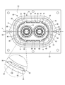
- FIG. 2 is a front view of the grommet unit shown in FIG.
- FIG. 3 is an exploded perspective view of the grommet unit shown in FIG.
- FIG. 4 is an exploded perspective view of the grommet unit shown in FIG. 1 at another angle.
- FIG. 5 is a sectional view taken along line VV of FIG.
- FIG. 6 is a perspective view of the grommet unit according to the second embodiment.
- FIG. 7 is a front view of the grommet unit shown in FIG.
- FIG. 8 is an exploded perspective view of the grommet unit shown in FIG.
- the grommet unit of the present disclosure is (1) A grommet unit that is mounted on the mounting surface of the mounted body, and is superposed on the grommet with a tubular grommet having a concave groove on the surface, so that the grommet is placed in the first direction with respect to the mounted body.
- the grommet is provided with a bracket to be pressed in the grommet and a communication passage formed by covering the concave groove of the grommet with the bracket, and the communication passage is a first end portion communicating between the bracket and the overlapping surface of the mounting surface.
- a grommet unit having a second end portion communicating with a portion where the grommet and the bracket are not overlapped.
- the water that has entered between the overlapping surfaces of the bracket and the mounting surface is discharged from the first end portion to the second end portion of the communication passage. Therefore, even if water vigorously enters between the bracket and the overlapping surface of the mounting surface, the water pressure acting on the seal portion of the grommet pressed against the attached body is reduced, and the water enters the inner circumference of the grommet. It is possible to prevent the vehicle from entering the vehicle interior.
- the concave grooves at a plurality of locations in the circumferential direction of the grommet.
- the total flow rate of the communication passages is increased, and the water pressure acting on the seal portion of the grommet is further reduced by the improvement of the drainage performance by the communication passages, so that the water is stopped. Performance can be improved.
- the bracket includes an insertion hole through which the grommet is inserted and a fixing portion fixed to the attached body, and the fixing portion is separated from each other in a second direction along the circumferential direction of the insertion hole. It is preferable that the first end portion of the communication passage is arranged between the plurality of fixed portions in the second direction.
- a gap is likely to be formed between the bracket and the attached body, and water enters between the bracket and the attached body rather than a portion closer to the fixed portion. It may occur easily. Therefore, if the first end of the communication passage is arranged at a position away from the fixed portion, the water that has entered between the bracket and the attached body at the position away from the fixed portion is quickly guided to the communication passage. The water pressure that is drained through the communication passage and acts on the seal portion of the grommet can be efficiently reduced. When a plurality of communication passages are provided, the above effect can be obtained if at least one first end of the communication passage is arranged at a position away from the fixed portion.
- the grommet has a first surface that is overlapped with the bracket in the first direction, and the groove has a hydraulic action portion that opens to the first surface. Since the pressure of water flowing through the portion formed by the hydraulic pressure acting portion in the communication passage acts on the grommet in the first direction, the grommet is pressed toward the attached body side by the water pressure. Therefore, when water enters between the bracket and the attached body, the liquidtightness (water stopping property) between the grommet and the attached body is improved.
- the grommet includes an annular mounting portion arranged between the bracket and the facing surface of the mounted body, the annular mounting portion has the first surface, and the annular mounting portion. Is preferably provided with an annular sealing lip that projects toward the attached body on the side opposite to the first surface.
- the first surface and the sealing lip are provided on each one side of the annular mounting portion in the first direction, the pressure of water flowing through the hydraulic acting portion acting in the first direction with respect to the annular mounting portion is for sealing. It is transmitted more directly to the lip. Therefore, the sealing lip is efficiently pressed against the attached body, and the liquidtightness between the grommet and the attached body due to the pressing of the sealing lip against the attached body is effectively ensured.
- the outer peripheral surface of the sealing lip is arranged at the same position as the groove bottom surface of the concave groove at the first end portion in the radial direction of the grommet.
- the first area which is the area of the portion of the surface of the grommet that does not come into contact with the bracket due to the concave groove, is made larger than the second area, which is the area of the portion of the surface of the grommet that comes into contact with the bracket. It is preferable to have. According to this, a large passage cross-sectional area of the continuous passage is secured, and the drainage performance by the continuous passage is enhanced, so that the liquidtightness between the grommet and the attached body is ensured. When a plurality of recessed grooves are provided, the total cross-sectional area of the plurality of passages is secured to be large, so that the sealing performance can be improved by improving the drainage performance.
- the bracket has an annular shape, the grommet is inserted through the bracket, and the grommet has a protruding portion that protrudes from the bracket in a third direction opposite to the first direction, and the concave groove is formed. It extends beyond the bracket to the protrusion of the grommet, and the grommet is locked to the end face of the bracket in the third direction to limit the movement of the grommet with respect to the bracket in the first direction. It is preferable that a stop portion is provided and the locking portion is provided at a portion deviating from the concave groove in the circumferential direction.
- the concave groove extends to the protruding portion, the water discharged from the second end of the communication passage is discharged toward the outer periphery at the end on the third direction side of the grommet.
- the grommet unit 10 of the first embodiment includes a grommet 12 and a bracket 14 for attaching the grommet 12 to a panel 52 (described later) as an attached body.
- the upward direction will be described as the Z direction in FIG. 1
- the front direction will be described as the X direction in FIG. 1
- the right direction will be described as the Y direction in FIG.
- the rearward direction which is the direction opposite to the X direction
- the frontward direction which is the X direction
- the third direction is referred to as the third direction.
- the upward, forward, and right directions referred to here do not necessarily correspond to the upward, forward, and right directions of the vehicle to which the grommet unit 10 is attached. Further, for a plurality of the same members, a reference numeral may be added to only a part of the members, and the reference numeral may be omitted for other members.
- the grommet 12 is a member exhibiting rubber-like elasticity, and is formed of, for example, rubber or a resin elastomer. As shown in FIGS. 1 to 5, the grommet 12 includes a base portion 16 that is superposed on a vehicle panel 52, which will be described later, and a tubular portion 18 that projects forward from the base portion 16.
- the base portion 16 has a substantially oval-shaped outer peripheral shape having a straight portion in the front view shown in FIG.
- the base portion 16 has two electric wire insertion holes 20 and 20 penetrating in the front-rear direction, and the electric wire insertion holes 20 and 20 are arranged side by side in the long axis direction of the base portion 16.
- the base portion 16 has a rear portion having a larger diameter than the front portion and a front portion having a protruding portion 22.
- the protruding portion 22 includes a locking portion 24 that protrudes toward the outer periphery.
- the front end surface of the locking portion 24 is a guide inclined surface 26 that inclines inward in the radial direction toward the front.
- the rear end surface of the locking portion 24 is a locking plane 28 that extends substantially orthogonal to the front-rear direction.
- the locking portion 24 faces the annular mounting portion 30, which will be described later, at a distance from the front.
- the rear portion of the base portion 16 includes an annular mounting portion 30 that protrudes to the outer periphery from the protruding portion 22.
- the front surface of the annular mounting portion 30 is a planar first surface 31 that extends substantially orthogonally to the front-rear direction.
- the annular mounting portion 30 is provided with a sealing lip 32 that projects rearward.
- the sealing lip 32 has a double structure having an outer peripheral lip 34 and an inner peripheral lip 36.
- the outer peripheral lip 34 and the inner peripheral lip 36 each have a continuous annular shape over the entire circumference in the circumferential direction, the outer peripheral lip 34 has a larger diameter than the inner peripheral lip 36, and the outer peripheral lip 34 becomes the inner peripheral lip 36.
- Both the outer peripheral lip 34 and the inner peripheral lip 36 have a tapered cross-sectional shape that narrows toward the tip.
- the outer peripheral lip 34 and the inner peripheral lip 36 project to the second surface 37 located on the opposite side of the first surface 31 in the annular mounting portion 30, and are arranged at radial positions overlapping the first surface 31 in the front-rear direction. There is.
- a groove 38 is formed in the base 16 of the grommet 12.
- the concave groove 38 is separated from the groove base end portion 40 that opens on the outer peripheral surface of the annular mounting portion 30, the hydraulic action portion 42 that opens on the first surface 31 that is the front surface of the annular mounting portion 30, and the annular mounting portion 30.
- a groove tip portion 44 that opens on the outer peripheral surface of the front portion of the base portion 16 is continuously provided.
- the concave groove 38 extends in the front-rear direction at the groove base end portion 40 and the groove tip portion 44, and extends in the radial direction of the grommet 12 at the hydraulic pressure acting portion 42.
- the concave groove 38 continuously extends from the rear end of the base portion 16 to the front end of the base portion 16, and the groove tip portion 44 extends to the protruding portion 22.
- the concave grooves 38 are provided at a plurality of positions of the base portion 16, and in the present embodiment, the six concave grooves 38 are arranged apart from each other in the circumferential direction of the base portion 16.
- the groove cross-sectional shape of the concave groove 38 is not particularly limited, but in the present embodiment, it is a semicircular cross section.
- the groove tip 44 of the concave groove 38 is open to the outer peripheral surface of the protruding portion 22 at the groove opening 45 in which the locking portion 24 is not partially formed.
- the locking portion 24 is provided at a portion that is deviated from the groove opening 45 in which the groove tip portion 44 of the concave groove 38 is formed in the circumferential direction.
- the width dimension of the groove opening 45 is larger than the width dimension of the concave groove 38, and the concave groove 38 opens in a part of the groove opening 45 in the width direction.
- the groove bottom surface 46 of the concave groove 38 at the rear end of the groove base end portion 40 is arranged at substantially the same radial position as the lip outer surface 47 which is the outer peripheral surface of the outer peripheral lip 34, and is arranged with the groove bottom surface 46.
- the outer surface 47 of the lip is smoothly continuous. Since the concave groove 38 of the present embodiment has a substantially semicircular cross section, the groove bottom surface 46 of the concave groove 38 is arranged at a substantially same radial position as the lip outer surface 47 at the portion where the depth is maximum. As described above, the groove bottom surface 46 and the lip outer surface 47 may be arranged at substantially the same radial position at least in part.
- the groove bottom surface 46 of the concave groove 38 is arranged at substantially the same radial position as the lip outer surface 47 when the groove bottom surface 46 and the lip outer surface 47 are continuous with a certain level difference or inclination. Is also included to the extent that it can be considered to be in substantially the same position. Specifically, the groove bottom surface 46 and the lip outer surface 47 of the concave groove 38 can be regarded as substantially the same position as long as the radial position deviation is within 1 mm.
- the tubular portion 18 projects forward from the peripheral edge of the opening of the electric wire insertion hole 20 in the base portion 16.
- the two tubular portions 18, 18 are arranged side by side in the left-right direction, which is the long axis direction of the base portion 16.
- a fastening piece 48 is integrally formed at the tip of the tubular portion 18.
- the fastening piece 48 has an arcuate cross section extending in the circumferential direction and projects forward from the tip of the tubular portion 18.
- the fastening piece 48 is formed with a positioning groove 50 extending in the circumferential direction so as to open on the outer peripheral surface.
- the base portion 16 has a shape in which the peripheral edge portion of the opening of the electric wire insertion hole 20 connected to the tubular portion 18 is thin and has a slack in the thickness direction, and the change and position of the direction of the tubular portion 18 relative to the base portion 16 are changed. The change of vibration is allowed, and the vibration transmission from the cylinder portion 18 to the base portion 16 is reduced.
- the grommet 12 is superposed on the panel 52 of the vehicle.
- the panel 52 is a member that constitutes the body and chassis of the vehicle and partitions the interior of the vehicle from the outside of the vehicle, and is composed of, for example, a metal plate.
- the outer surface of the vehicle interior of the panel 52 is a mounting surface 53 to which the grommet unit 10 is mounted.
- the panel 52 includes a through hole 54 that penetrates in the thickness direction.
- the through hole 54 has an oval shape corresponding to the grommet 12 when viewed from the front, and has a diameter smaller than that of the annular mounting portion 30 so that the annular mounting portion 30 of the grommet 12 is overlapped with the opening peripheral edge of the through hole 54. It is said that.
- the panel 52 is provided with a plurality of bolt holes 56 penetrating in the thickness direction on the outer peripheral side of the through holes 54.
- Bracket 14 A bracket 14 is superposed on the base 16 of the grommet 12.
- the bracket 14 is made of metal or the like, and has a substantially oval ring plate shape corresponding to the grommet 12 as a whole.
- the bracket 14 has an insertion hole 58 that penetrates in the front-rear direction.
- the bracket 14 includes a base end wall portion 60 that is overlapped with the outer peripheral surface of the annular mounting portion 30 of the grommet 12, an intermediate wall portion 62 that extends from the front end of the base end wall portion 60 toward the inner circumference, and an intermediate wall portion 62.
- a tip wall portion 64 extending forward from the inner peripheral end portion of the above is integrally provided.
- a fixing portion 66 is provided at the rear end of the base end wall portion 60 of the bracket 14.
- the fixing portions 66 have a plate shape, and preferably, a plurality of fixing portions 66 are provided at positions separated from each other in a second direction along the circumferential direction of the insertion hole 58.
- a pair of fixing portions 66, 66 are provided so as to project from the base end wall portion 60 toward both outer sides in the radial direction of the insertion hole 58.
- Bolt holes 68 penetrating in the front-rear direction, which is the plate thickness direction, are formed in each fixing portion 66.
- a reinforcing rib 70 projecting toward the outer periphery is integrally formed.
- the reinforcing rib 70 is provided between the pair of fixing portions 66, 66 in the second direction, and is continuous with the pair of fixing portions 66, 66 in the second direction.
- the bracket 14 is a press fitting, and the entire bracket 14 including the fixing portions 66, 66 and the reinforcing rib 70 has an integral structure.
- the intermediate wall portion 62 of the bracket 14 is attached to the first surface 31 of the annular mounting portion 30 of the grommet 12 in a state where the grommet 12 is superposed on the opening peripheral portion of the through hole 54 of the panel 52. And they are superposed in the first direction.
- the fixing portions 66, 66 are overlapped with respect to the panel 52 in the first direction, and the panel 52 is formed by a bolt (not shown) inserted into the bolt hole 68 of the fixing portion 66 and the bolt hole 56 of the panel 52. Is fixed to.
- the grommet unit 10 including the grommet 12 and the bracket 14 is configured to be mounted on the panel 52.
- the protruding portion 22 of the base 16 of the grommet 12 is inserted into the insertion hole 58 of the bracket 14 and protrudes forward from the front end of the bracket 14.
- the locking portion 24 provided on the protruding portion 22 is overlapped on the front side with respect to the front end surface of the bracket 14, and the protruding portion 22 can be pulled out from the bracket 14 to the rear to lock the locking portion 24. It is prevented by locking the flat surface 28 and the bracket 14.
- the guide inclined surface 26 constituting the front surface of the locking portion 24 comes into contact with the bracket 14.
- the protruding portion 22 is guided to an appropriate position with respect to the bracket 14, and the protruding portion 22 can be easily inserted into the insertion hole 58 of the bracket 14.
- the locking portion 24 is less likely to be caught in the bracket 14, and the grommet 12 is easily inserted into the insertion hole 58 of the bracket 14.
- the annular mounting portion 30 of the grommet 12 is sandwiched in the front-rear direction between the intermediate wall portion 62 of the bracket 14 and the facing surface of the panel 52, and the sealing lip 32 protruding from the annular mounting portion 30 toward the panel 52 is provided. , Is pressed against the panel 52 in the first direction.
- the grommet 12 is positioned with respect to the through hole 54 of the panel 52, and the annular mounting portion 30 of the grommet 12 is overlapped with the opening peripheral edge of the through hole 54 in the panel 52.
- the through hole 54 communicates with the electric wire insertion holes 20 and 20 of the base 16 and the inner holes of the tubular portions 18 and 18 in the grommet 12.
- the sealing lip 32 is continuously pressed against the panel 52 around the through hole 54 over the entire circumference.
- the electric wires 72 and 72 penetrate through the through hole 54 of the panel 52.
- the electric wire 72 is an insulated electric wire in which an insulating coating such as a synthetic resin is provided on the outside of a core wire composed of a single wire or a stranded wire of a conductor.
- the core wire and the insulating coating of the electric wire 72 are formed of a known general material.
- the electric wires 72 and 72 penetrate the through holes 54, and penetrate the electric wire insertion holes 20 and 20 of the base 16 and the inner holes of the tubular portions 18 and 18 that communicate with the through holes 54.
- the outer peripheral surface of the electric wire 72 is pressed against the inner peripheral surface of the tubular portion 18, and the overlapping surfaces of the electric wire 72 and the tubular portion 18 are liquid-tightly sealed.
- the tubular portion 18 through which the electric wire 72 penetrates may be fixed to the electric wire 72 by winding a band or the like (not shown) around the fastening piece 48 and tightening the cylinder portion 18.
- a band or the like (not shown) around the fastening piece 48 and tightening the cylinder portion 18.
- the electric wire 72 and the grommet 12 are positioned with each other in the length direction of the electric wire 72, and the sealing performance between the electric wire 72 and the tubular portion 18 is improved. Since the band or the like is wound around the bottom surface of the positioning groove 50 of the fastening piece 48, it becomes difficult for the band or the like to come off from the fastening piece 48.
- ⁇ Communication passage 74> By attaching the bracket 14 to the base 16 of the grommet 12, the opening of the groove 38 formed in the base 16 of the grommet 12 is covered by the bracket 14. As a result, a communication passage 74 formed by utilizing the concave groove 38 is provided between the base portion 16 of the grommet 12 and the overlapping surface of the bracket 14. The first end 76, which is one end of the communication passage 74, communicates between the mounting surface 53 of the panel 52 and the facing surface of the bracket 14 in the front-rear direction on the rear surface of the grommet 12 on the mounting side to the panel 52. doing.
- the second end 78 which is the other end of the communication passage 74, is located at the front end of the bracket 14 and is open to the external space 80 in front of the bracket 14, which is a portion where the bracket 14 is not overlapped.
- the portion where the bracket 14 is overlapped with the grommet 12 does not mean only the portion where the bracket 14 is overlapped with the grommet 12 in a contact state, but the bracket 14 is overlapped with the grommet 12 so as to face each other with a gap. Includes site. Therefore, the portion where the bracket 14 is not superposed on the grommet 12 means a portion of the grommet 12 which is separated from the bracket 14 and does not face the bracket 14.
- the second end 78 of the communication passage 74 is open toward the end of the concave groove 38 extending forward from the bracket 14.
- the first end 76 is open toward the panel 52 side, and the second end 78 is open toward the opposite side of the panel 52. In other words, the first end portion 76 is open toward the rear in the first direction, and the second end portion 78 is open toward the front in the third direction. Then, the first end portion 76 communicates with the flooded region 82, and the second end portion 78 communicates with the external space 80.
- the flooded area 82 is a space defined between the base end wall portion 60 and the reinforcing rib 70 of the bracket 14 and the facing surfaces in the front-rear direction of the mounting surface 53 of the panel 52, and the bracket 14 and the panel 52 are overlapped with each other. This is the area where water can enter through the mating surfaces.
- the external space 80 is a region outside the internal space between the bracket 14 and the panel 52, and is outside the flooded region 82 which is a part of the internal space.
- a plurality of communication passages 74 are provided in the circumferential direction of the grommet unit 10.
- the six communication passages 74 are arranged at positions separated from each other in the circumferential direction.
- the communication passage 74 has a first end portion 76 open to the flooded region 82, and is located on the outer peripheral side of the outer peripheral lip 34 of the sealing lip 32 arranged on the inner circumference of the flooded region 82. positioned.
- the groove bottom surface 46 of the concave groove 38 at the first end portion 76 is arranged at substantially the same radial position as the lip outer surface 47 which is the outer peripheral surface of the outer peripheral lip 34, it is inside the communication passage 74.
- the peripheral end is arranged at substantially the same radial position with respect to the lip outer surface 47 of the lip outer surface 47.
- the communication passage 74 is formed by covering the opening of the concave groove 38 formed in the grommet 12 with the bracket 14, and does not require processing such as forming a groove or a hole in the bracket 14.
- the concave groove 38 that opens on the surface of the grommet 12 can be formed at the time of molding the grommet 12, and no secondary processing is required. Therefore, the communication passage 74 can be easily formed, and the grommet unit 10 provided with the communication passage 74 can be easily manufactured.
- the first is the area of the portion where the concave groove 38 is formed and does not come into contact with the bracket 14 on the outer peripheral surface of the base portion 16 on which the bracket 14 is overlapped and the front surface (first surface 31) of the annular mounting portion 30.
- the area is made smaller than the second area, which is the area of the portion that comes into contact with the bracket 14 outside the concave groove 38.
- the water pressure acting on the sealing lip 32 is reduced by the communication passage 74. That is, the water that has entered the flooded area 82 flows from the first end portion 76 of the communication passage 74 opened between the bracket 14 and the panel 52 into the communication passage 74, flows through the communication passage 74, and flows through the communication passage 74. It is discharged from the second end 78 to the external space 80.
- the water that has entered the flooded region 82 surrounded by the bracket 14, the panel 52, and the outer peripheral lip 34 is discharged to the external space 80 through the communication passage 74 that communicates with the flooded region 82, so that the water pressure in the flooded region 82 is increased.
- the rise can be reduced or eliminated. Therefore, the water pressure exerted on the sealing lip 32 forming a part of the wall portion of the flooded region 82 can be suppressed, and the sealing by the sealing lip 32 can be prevented from being released by the action of a large water pressure. ..
- the total passage cross-sectional area of the passages 74 is increased. Therefore, the water that has entered the flooded area 82 through the plurality of communication passages 74 is quickly discharged, and the action of water pressure on the sealing lip 32 can be suppressed more effectively. Further, since the water that has entered the inundation region 82 is quickly discharged through the communication passage 74 that is close to the infiltration position of the water in the inundation region 82, it is possible to promptly prevent the increase in water pressure acting on the sealing lip 32. can.
- the reinforcing rib 70 of the bracket 14 is provided at a position away from the fixing portions 66, 66, the pressing against the panel 52 tends to be weaker than the fixing portions 66, 66 directly fixed by the bolt. Further, the reinforcing rib 70 may be provided so as to be slightly separated from the panel 52 so as not to prevent the fixing portions 66, 66 from being fixed to the panel 52. Therefore, water easily enters the flooded region 82 between the reinforcing ribs 70 and the panel 52 that have come off the fixing portions 66 and 66.
- At least one of the first end portions 76 of the communication passage 74 is arranged between the fixed portions 66 and 66 in the second direction which is the circumferential direction of the bracket 14, and water enters from the outside in the inundation region 82. It is located close to the easy-to-use part. As a result, the water that has entered the flooded area 82 is quickly discharged through the communication passage 74 that is close to the flooded position.
- an intermediate portion formed by the hydraulic pressure acting portion 42 of the concave groove 38 extends in the radial direction between the annular mounting portion 30 of the grommet 12 and the intermediate wall portion 62 of the bracket 14.
- the pressure of water flowing through the portion of the communication passage 74 formed by the hydraulic action portion 42 acts on the annular mounting portion 30 of the grommet 12 toward the panel 52 side.
- the sealing lip 32 of the annular mounting portion 30 is strongly pressed against the panel 52 by the water pressure acting on the annular mounting portion 30 in the hydraulic pressure acting portion 42. As a result, the liquidtightness of the sealing lip 32 can be improved between the overlapping surfaces of the annular mounting portion 30 and the panel 52, and water ingress can be prevented.
- the hydraulic action portion 42 of the sealing lip 32 and the concave groove 38 is partially provided at the same position in the radial direction, and is projected in the front-rear direction in which the sealing lip 32 is pressed against the panel 52. It partially overlaps. Therefore, the water pressure exerted on the annular mounting portion 30 in the hydraulic pressure acting portion 42 acts directly on the sealing lip 32 in the pressing direction against the panel 52, and the sealing lip 32 is strongly pressed by the panel 52. Therefore, the sealing performance can be efficiently improved.
- the sealing lip 32 is provided on the outer peripheral portion of the annular mounting portion 30 of the grommet 12, and the pressure of water entering the water immersion region 82 located on the outer periphery of the sealing lip 32 is applied to the panel 52 with respect to the annular mounting portion 30. It is difficult to act toward the opposite side. Therefore, it is possible to prevent the pressing of the sealing lip 32 against the panel 52 from being weakened by the water pressure, and effectively obtain the sealing performance by the sealing lip 32.
- the lip outer surface 47 which is the outer peripheral surface of the outer peripheral lip 34 constituting the sealing lip 32, is arranged at the same position as the groove bottom surface 46 of the concave groove 38 in the radial direction, and the outer peripheral lip 34 is the annular mounting portion 30 of the grommet 12. It is provided at the outer peripheral end of the. Therefore, it is difficult for water to enter between the annular mounting portion 30 and the facing surface of the panel 52, and it is possible to more effectively prevent the pressing of the sealing lip 32 against the panel 52 from being weakened by the water pressure.
- the concave groove 38 forming the inner peripheral side wall surface of the communication passage 74 at the second end 78 of the communication passage 74 extends further forward than the second end 78. Therefore, the water that has reached the second end 78 through the communication passage 74 is discharged to the external space 80 from the opening of the concave groove 38 toward the outer periphery of the grommet 12 in front of the second end 78. Therefore, the water discharged from the second end 78 is unlikely to come into contact with the front surface of the grommet 12 or the electric wire 72.
- the grommet unit 90 of the second embodiment includes a grommet 92 and a bracket 14. As shown in FIG. 8, the grommet 92 includes a base portion 94 and two tubular portions 18 and 18.
- the base portion 94 includes a plurality of locking portions 96 that protrude toward the outer periphery at the protruding portion 22.
- the locking portion 96 of the present embodiment has a smaller width dimension in the circumferential direction than the locking portion 24 of the first embodiment, and more than the locking portion 24 of the first embodiment in the circumferential direction of the base portion 94. They are arranged apart from each other.
- a plurality of concave grooves 98 are formed in the base portion 94.
- the concave groove 98 opens to the outer peripheral surface of the base portion 94 and the first surface 31 which is the front surface of the annular mounting portion 30, and extends continuously from the rear end to the front end of the base portion 94.
- the concave groove 98 is arranged at a position separated from the locking portion 96 in the circumferential direction of the base portion 94, and is opened in the groove opening 45 provided between the adjacent locking portions 96, 96.
- the concave groove 98 of the present embodiment has a larger groove width dimension than the concave groove 38 of the first embodiment. Further, the number of concave grooves 98 formed is larger than that of the concave grooves 38 of the first embodiment. Then, on the outer peripheral surface of the base portion 94 on which the bracket 14 is overlapped and the front surface (first surface 31) of the annular mounting portion 30, the first area, which is the area of the portion where the concave groove 98 is formed and does not come into contact with the bracket 14, is defined as the first area. It is made larger than the second area, which is the area of the portion that comes into contact with the bracket 14 outside the concave groove 98.
- the base 94 is overlapped with the panel 52 of the vehicle, and the base 94 is attached to the panel 52 by the bracket 14, as in the first embodiment.
- the base portion 94 of the grommet 92 has a protruding portion 22 having a locking portion 96 protruding forward of the bracket 14 through an insertion hole 58 of the bracket 14.
- the surface of the portion excluding the protruding portion 22 is covered with the bracket 14, and the opening of the concave groove 98 is covered with the bracket 14, so that the communication passage 100 is formed.
- the first area which is the area of the portion that does not contact the bracket 14 due to the concave groove 98
- the second area which is the area of the portion that contacts the bracket 14. .. Therefore, in the grommet unit 90 of the present embodiment, the total passage cross-sectional area of the communication passage 100 is larger than the total passage cross-sectional area of the communication passage 74 in the first embodiment, and the total flow rate of the communication passage 100 is increased. .. In the communication passage 100, the total flow rate is increased due to the large width dimension of each communication passage 100 and the large number of formations of the communication passage 100.
- the grommet unit 90 even if water enters between the bracket 14 and the panel 52, the drainage through the communication passage 100 prevents the water pressure from increasing, and the grommet 92 and the panel 52 It is possible to secure the sealing performance between the grommets.
- the total flow rate which is the total flow rate of the plurality of communication passages 100, is increased, the water that has entered between the bracket 14 and the panel 52 is discharged more efficiently through the communication passage 100.
- the width dimension of the communication passage 100 is large. Since the area of action of water pressure is large, a larger force is exerted on the annular mounting portion 30. Therefore, the sealing performance between the annular mounting portion 30 and the panel 52 is more effectively enhanced by the pressure of the water flowing through the communication passage 100.
- the grommet 12 having a structure in which two tubular portions 18 and 18 are provided on one base portion 16 is illustrated, but only one tubular portion 18 is provided for one base portion 16. It may be provided, or three or more may be provided.
- the base portion 16 of the above embodiment has an oval shape having a straight portion as the outer peripheral shape in the front view, but the outer peripheral shape of the base portion is not particularly limited, and is circular in the front view, for example. And so on. Further, the inner peripheral shape of the bracket can be appropriately changed according to the outer peripheral shape of the base portion.
- the sealing lip 32 provided on the base 16 is not limited to the double structure including the outer peripheral lip 34 and the inner peripheral lip 36 as shown in the above embodiment.
- the sealing lip 32 is preferably provided on the outer peripheral portion of the grommet 12, but may be provided, for example, so as to project rearward on the inner peripheral side of the grommet 12.
- the passage cross-sectional shape and the passage cross-sectional area of the continuous passage 74 may be substantially constant in the passage length direction, or may change stepwise or gradually in the passage length direction.
- the number and arrangement of the fixing portions 66 provided on the bracket 14 are not particularly limited, but in order to effectively fix the bracket 14 to the panel 52, a plurality of fixing portions 66 are provided in the circumferential direction of the bracket 14. It is desirable that they are provided at positions separated from each other in the (second direction).
- Grommet unit (Embodiment 1) 12 Glomet 14 Bracket 16 Base 18 Cylinder 20 Wire insertion hole 22 Protruding part 24 Locking part 26 Guide inclined surface 28 Locking flat surface 30 Ring mounting part 31 First surface 32 Sealing lip 34 Outer lip 36 Inner peripheral lip 37 No.
Landscapes
- Engineering & Computer Science (AREA)
- General Engineering & Computer Science (AREA)
- Mechanical Engineering (AREA)
- Architecture (AREA)
- Civil Engineering (AREA)
- Structural Engineering (AREA)
- Installation Of Indoor Wiring (AREA)
- Insulating Bodies (AREA)
Priority Applications (3)
| Application Number | Priority Date | Filing Date | Title |
|---|---|---|---|
| CN202080097948.7A CN115280621B (zh) | 2020-03-09 | 2020-10-23 | 护线套单元 |
| US17/908,739 US20230127049A1 (en) | 2020-03-09 | 2020-10-23 | Grommet unit |
| JP2022505751A JP7336066B2 (ja) | 2020-03-09 | 2020-10-23 | グロメットユニット |
Applications Claiming Priority (2)
| Application Number | Priority Date | Filing Date | Title |
|---|---|---|---|
| JP2020-040251 | 2020-03-09 | ||
| JP2020040251 | 2020-03-09 |
Publications (1)
| Publication Number | Publication Date |
|---|---|
| WO2021181741A1 true WO2021181741A1 (ja) | 2021-09-16 |
Family
ID=77671485
Family Applications (1)
| Application Number | Title | Priority Date | Filing Date |
|---|---|---|---|
| PCT/JP2020/039827 Ceased WO2021181741A1 (ja) | 2020-03-09 | 2020-10-23 | グロメットユニット |
Country Status (4)
| Country | Link |
|---|---|
| US (1) | US20230127049A1 (https=) |
| JP (1) | JP7336066B2 (https=) |
| CN (1) | CN115280621B (https=) |
| WO (1) | WO2021181741A1 (https=) |
Cited By (1)
| Publication number | Priority date | Publication date | Assignee | Title |
|---|---|---|---|---|
| WO2022181362A1 (ja) * | 2021-02-24 | 2022-09-01 | 住友電装株式会社 | グロメット |
Families Citing this family (2)
| Publication number | Priority date | Publication date | Assignee | Title |
|---|---|---|---|---|
| JP2023107253A (ja) * | 2022-01-22 | 2023-08-03 | 古河電気工業株式会社 | グロメットインナ及びグロメット |
| US20240280123A1 (en) * | 2023-02-16 | 2024-08-22 | Illinois Tool Works Inc. | Compressing Snap Grommet |
Citations (2)
| Publication number | Priority date | Publication date | Assignee | Title |
|---|---|---|---|---|
| JPS6246884U (https=) * | 1985-09-10 | 1987-03-23 | ||
| JP2016210214A (ja) * | 2015-04-30 | 2016-12-15 | 住友電装株式会社 | グロメット用ブラケット |
Family Cites Families (10)
| Publication number | Priority date | Publication date | Assignee | Title |
|---|---|---|---|---|
| JPH08154328A (ja) * | 1994-11-28 | 1996-06-11 | Sumitomo Wiring Syst Ltd | グロメットを取り付けたワイヤハーネスの防水構造 |
| US6088876A (en) * | 1998-09-30 | 2000-07-18 | Lucent Technologies, Inc. | Sealing grommet |
| JP2003141959A (ja) * | 2001-11-06 | 2003-05-16 | Fujikura Ltd | グロメット |
| DE10332035B4 (de) * | 2002-08-07 | 2011-12-15 | Volkswagen Ag | Dichtungstülle für eine Leitungsdurchführung in einer Wandung |
| US6897380B2 (en) * | 2002-11-29 | 2005-05-24 | Sumitomo Wiring Systems, Ltd. | Grommet for a wire harness |
| JP5814622B2 (ja) * | 2011-05-26 | 2015-11-17 | 大和化成工業株式会社 | グロメット |
| CN202651712U (zh) * | 2012-06-25 | 2013-01-02 | 德尔福派克电气系统有限公司 | 一种用于汽车线束的保护装置 |
| JP5880457B2 (ja) * | 2013-01-17 | 2016-03-09 | 住友電装株式会社 | グロメット |
| MX373043B (es) * | 2015-03-03 | 2020-05-26 | Leoni Bordnetz Sys Gmbh | Arandela de sellado y paso de cable con una arandela de sellado. |
| DE102015220318A1 (de) * | 2015-10-19 | 2017-04-20 | Lisa Dräxlmaier GmbH | Tülle sowie verfahren zum herstellen einer solchen tülle |
-
2020
- 2020-10-23 US US17/908,739 patent/US20230127049A1/en not_active Abandoned
- 2020-10-23 WO PCT/JP2020/039827 patent/WO2021181741A1/ja not_active Ceased
- 2020-10-23 JP JP2022505751A patent/JP7336066B2/ja active Active
- 2020-10-23 CN CN202080097948.7A patent/CN115280621B/zh active Active
Patent Citations (2)
| Publication number | Priority date | Publication date | Assignee | Title |
|---|---|---|---|---|
| JPS6246884U (https=) * | 1985-09-10 | 1987-03-23 | ||
| JP2016210214A (ja) * | 2015-04-30 | 2016-12-15 | 住友電装株式会社 | グロメット用ブラケット |
Cited By (4)
| Publication number | Priority date | Publication date | Assignee | Title |
|---|---|---|---|---|
| WO2022181362A1 (ja) * | 2021-02-24 | 2022-09-01 | 住友電装株式会社 | グロメット |
| JP2022129142A (ja) * | 2021-02-24 | 2022-09-05 | 住友電装株式会社 | グロメット |
| JP7344913B2 (ja) | 2021-02-24 | 2023-09-14 | 住友電装株式会社 | グロメット |
| US12374475B2 (en) | 2021-02-24 | 2025-07-29 | Sumitomo Wiring Systems, Ltd. | Grommet |
Also Published As
| Publication number | Publication date |
|---|---|
| CN115280621A (zh) | 2022-11-01 |
| US20230127049A1 (en) | 2023-04-27 |
| JPWO2021181741A1 (https=) | 2021-09-16 |
| CN115280621B (zh) | 2024-05-14 |
| JP7336066B2 (ja) | 2023-08-31 |
Similar Documents
| Publication | Publication Date | Title |
|---|---|---|
| JP5874977B2 (ja) | グロメット及びグロメット付き取付部材 | |
| WO2021181741A1 (ja) | グロメットユニット | |
| CN107431344B (zh) | 护线环以及带护线环的线束 | |
| JP5387541B2 (ja) | グロメット | |
| WO2012124203A1 (ja) | グロメットのシール構造 | |
| JP7135878B2 (ja) | グロメット | |
| WO2017098885A1 (ja) | コネクタ | |
| WO2018139267A1 (ja) | ワイヤハーネス | |
| CN112636283A (zh) | 索环以及线束 | |
| US10797432B2 (en) | Connector including a housing into which a cable is inserted and a rear housing to guide the cable and maintain shapes of portions of the cable | |
| US11201432B2 (en) | Connector | |
| JP6946362B2 (ja) | グロメット、及び、ワイヤハーネス | |
| JP4985194B2 (ja) | コネクタ | |
| US20240425001A1 (en) | Grommet | |
| JP5403349B2 (ja) | シールドコネクタ | |
| JP5229580B2 (ja) | シールドコネクタ | |
| JP2003009459A (ja) | モータの防水構造 | |
| WO2021187064A1 (ja) | ワイヤハーネス | |
| JP2014116997A (ja) | グロメット保護部材及び電線接続装置 | |
| JP4791014B2 (ja) | 防水コネクタ | |
| JP2011024280A (ja) | シール部材及びシール部材の製造方法 | |
| JP7463984B2 (ja) | グロメットアセンブリ及びワイヤハーネス | |
| JP6135736B2 (ja) | 電気機器のシールカバー | |
| CN115117824A (zh) | 护线套组件及线束 | |
| JP7256484B2 (ja) | グロメット |
Legal Events
| Date | Code | Title | Description |
|---|---|---|---|
| 121 | Ep: the epo has been informed by wipo that ep was designated in this application |
Ref document number: 20924639 Country of ref document: EP Kind code of ref document: A1 |
|
| ENP | Entry into the national phase |
Ref document number: 2022505751 Country of ref document: JP Kind code of ref document: A |
|
| NENP | Non-entry into the national phase |
Ref country code: DE |
|
| 122 | Ep: pct application non-entry in european phase |
Ref document number: 20924639 Country of ref document: EP Kind code of ref document: A1 |