WO2021181641A1 - モータ駆動装置および冷凍サイクル装置 - Google Patents
モータ駆動装置および冷凍サイクル装置 Download PDFInfo
- Publication number
- WO2021181641A1 WO2021181641A1 PCT/JP2020/010958 JP2020010958W WO2021181641A1 WO 2021181641 A1 WO2021181641 A1 WO 2021181641A1 JP 2020010958 W JP2020010958 W JP 2020010958W WO 2021181641 A1 WO2021181641 A1 WO 2021181641A1
- Authority
- WO
- WIPO (PCT)
- Prior art keywords
- motor
- mode
- rotation speed
- controller
- open
- Prior art date
- Legal status (The legal status is an assumption and is not a legal conclusion. Google has not performed a legal analysis and makes no representation as to the accuracy of the status listed.)
- Ceased
Links
Images


Classifications
-
- F—MECHANICAL ENGINEERING; LIGHTING; HEATING; WEAPONS; BLASTING
- F25—REFRIGERATION OR COOLING; COMBINED HEATING AND REFRIGERATION SYSTEMS; HEAT PUMP SYSTEMS; MANUFACTURE OR STORAGE OF ICE; LIQUEFACTION SOLIDIFICATION OF GASES
- F25B—REFRIGERATION MACHINES, PLANTS OR SYSTEMS; COMBINED HEATING AND REFRIGERATION SYSTEMS; HEAT PUMP SYSTEMS
- F25B49/00—Arrangement or mounting of control or safety devices
- F25B49/02—Arrangement or mounting of control or safety devices for compression type machines, plants or systems
- F25B49/025—Motor control arrangements
-
- H—ELECTRICITY
- H02—GENERATION; CONVERSION OR DISTRIBUTION OF ELECTRIC POWER
- H02P—CONTROL OR REGULATION OF ELECTRIC MOTORS, ELECTRIC GENERATORS OR DYNAMO-ELECTRIC CONVERTERS; CONTROLLING TRANSFORMERS, REACTORS OR CHOKE COILS
- H02P25/00—Arrangements or methods for the control of AC motors characterised by the kind of AC motor or by structural details
- H02P25/16—Arrangements or methods for the control of AC motors characterised by the kind of AC motor or by structural details characterised by the circuit arrangement or by the kind of wiring
- H02P25/18—Arrangements or methods for the control of AC motors characterised by the kind of AC motor or by structural details characterised by the circuit arrangement or by the kind of wiring with arrangements for switching the windings, e.g. with mechanical switches or relays
-
- F—MECHANICAL ENGINEERING; LIGHTING; HEATING; WEAPONS; BLASTING
- F25—REFRIGERATION OR COOLING; COMBINED HEATING AND REFRIGERATION SYSTEMS; HEAT PUMP SYSTEMS; MANUFACTURE OR STORAGE OF ICE; LIQUEFACTION SOLIDIFICATION OF GASES
- F25B—REFRIGERATION MACHINES, PLANTS OR SYSTEMS; COMBINED HEATING AND REFRIGERATION SYSTEMS; HEAT PUMP SYSTEMS
- F25B13/00—Compression machines, plants or systems, with reversible cycle
-
- F—MECHANICAL ENGINEERING; LIGHTING; HEATING; WEAPONS; BLASTING
- F25—REFRIGERATION OR COOLING; COMBINED HEATING AND REFRIGERATION SYSTEMS; HEAT PUMP SYSTEMS; MANUFACTURE OR STORAGE OF ICE; LIQUEFACTION SOLIDIFICATION OF GASES
- F25D—REFRIGERATORS; COLD ROOMS; ICE-BOXES; COOLING OR FREEZING APPARATUS NOT OTHERWISE PROVIDED FOR
- F25D21/00—Defrosting; Preventing frosting; Removing condensed or defrost water
- F25D21/002—Defroster control
-
- H—ELECTRICITY
- H02—GENERATION; CONVERSION OR DISTRIBUTION OF ELECTRIC POWER
- H02P—CONTROL OR REGULATION OF ELECTRIC MOTORS, ELECTRIC GENERATORS OR DYNAMO-ELECTRIC CONVERTERS; CONTROLLING TRANSFORMERS, REACTORS OR CHOKE COILS
- H02P27/00—Arrangements or methods for the control of AC motors characterised by the kind of supply voltage
- H02P27/04—Arrangements or methods for the control of AC motors characterised by the kind of supply voltage using variable-frequency supply voltage, e.g. inverter or converter supply voltage
- H02P27/06—Arrangements or methods for the control of AC motors characterised by the kind of supply voltage using variable-frequency supply voltage, e.g. inverter or converter supply voltage using DC to AC converters or inverters
-
- F—MECHANICAL ENGINEERING; LIGHTING; HEATING; WEAPONS; BLASTING
- F25—REFRIGERATION OR COOLING; COMBINED HEATING AND REFRIGERATION SYSTEMS; HEAT PUMP SYSTEMS; MANUFACTURE OR STORAGE OF ICE; LIQUEFACTION SOLIDIFICATION OF GASES
- F25B—REFRIGERATION MACHINES, PLANTS OR SYSTEMS; COMBINED HEATING AND REFRIGERATION SYSTEMS; HEAT PUMP SYSTEMS
- F25B2313/00—Compression machines, plants or systems with reversible cycle not otherwise provided for
- F25B2313/023—Compression machines, plants or systems with reversible cycle not otherwise provided for using multiple indoor units
- F25B2313/0233—Compression machines, plants or systems with reversible cycle not otherwise provided for using multiple indoor units in parallel arrangements
-
- F—MECHANICAL ENGINEERING; LIGHTING; HEATING; WEAPONS; BLASTING
- F25—REFRIGERATION OR COOLING; COMBINED HEATING AND REFRIGERATION SYSTEMS; HEAT PUMP SYSTEMS; MANUFACTURE OR STORAGE OF ICE; LIQUEFACTION SOLIDIFICATION OF GASES
- F25B—REFRIGERATION MACHINES, PLANTS OR SYSTEMS; COMBINED HEATING AND REFRIGERATION SYSTEMS; HEAT PUMP SYSTEMS
- F25B2700/00—Sensing or detecting of parameters; Sensors therefor
- F25B2700/15—Power, e.g. by voltage or current
- F25B2700/151—Power, e.g. by voltage or current of the compressor motor
-
- F—MECHANICAL ENGINEERING; LIGHTING; HEATING; WEAPONS; BLASTING
- F25—REFRIGERATION OR COOLING; COMBINED HEATING AND REFRIGERATION SYSTEMS; HEAT PUMP SYSTEMS; MANUFACTURE OR STORAGE OF ICE; LIQUEFACTION SOLIDIFICATION OF GASES
- F25B—REFRIGERATION MACHINES, PLANTS OR SYSTEMS; COMBINED HEATING AND REFRIGERATION SYSTEMS; HEAT PUMP SYSTEMS
- F25B2700/00—Sensing or detecting of parameters; Sensors therefor
- F25B2700/17—Speeds
- F25B2700/171—Speeds of the compressor
-
- Y—GENERAL TAGGING OF NEW TECHNOLOGICAL DEVELOPMENTS; GENERAL TAGGING OF CROSS-SECTIONAL TECHNOLOGIES SPANNING OVER SEVERAL SECTIONS OF THE IPC; TECHNICAL SUBJECTS COVERED BY FORMER USPC CROSS-REFERENCE ART COLLECTIONS [XRACs] AND DIGESTS
- Y02—TECHNOLOGIES OR APPLICATIONS FOR MITIGATION OR ADAPTATION AGAINST CLIMATE CHANGE
- Y02B—CLIMATE CHANGE MITIGATION TECHNOLOGIES RELATED TO BUILDINGS, e.g. HOUSING, HOUSE APPLIANCES OR RELATED END-USER APPLICATIONS
- Y02B30/00—Energy efficient heating, ventilation or air conditioning [HVAC]
- Y02B30/70—Efficient control or regulation technologies, e.g. for control of refrigerant flow, motor or heating
Definitions
- the present invention relates to a motor drive device that drives a motor having a plurality of phase windings that are not connected to each other, and a refrigeration cycle device including the motor drive device.
- a permanent magnet synchronous motor having multiple phase windings is used as a drive motor for a compressor mounted on a refrigeration cycle device such as an air conditioner.
- a permanent magnet synchronous motor also referred to as a DC brushless motor
- an open winding motor Open-Windings Motor having a configuration in which a plurality of phase windings are not connected to each other is known.
- the motor drive device that drives this open winding motor (abbreviated as a motor) energizes the first inverter that controls energization of one end of each phase winding of the motor and the other end of each phase winding of the motor.
- a second inverter to be controlled and a switch connected to each other at the other ends of each phase winding are provided, and each phase winding is star-connected (also referred to as a star-shaped connection) by closing the switch.
- the star connection mode in which the inverters are switched independently and the open winding mode in which the first and second inverters are switched in cooperation with each other with the phase windings disconnected by opening the switch are selectively set.
- the motor By setting the open winding mode, the motor can be driven at a high rotation speed, and by setting the star connection mode in the low rotation speed range, the motor can be driven with high efficiency, and thus from a high rotation speed to a low rotation speed. It is possible to drive the motor as efficiently as possible over a wide operating range. It achieves both an expansion of the operating range of the motor and an improvement in the efficiency of the motor drive device.
- a mechanical relay having a mechanical opening / closing contact As a switch for switching between the star connection mode and the open winding mode, for example, a mechanical relay having a mechanical opening / closing contact is used.
- This relay has an upper limit for the current flowing through the open / close contacts to ensure proper operation. This upper limit is generally called the rated current or the contact rated current (hereinafter referred to as the rated current). If an overcurrent exceeding this rated energizing current continues to flow through the switching contacts of the relay, the relay may fail.
- mechanical relays have a life depending on the number of operations. This life becomes shorter as the number of times of switching between the star connection mode and the open winding mode increases.
- An object of the embodiment of the present invention is to provide a refrigeration cycle apparatus capable of preventing an overcurrent from flowing to an on-off contact of a relay and reducing the number of times the relay is operated as much as possible, thereby extending the life of the relay. To provide.
- the motor drive device includes a motor having a plurality of phase windings that are not connected to each other; a first inverter that controls energization of one end of each phase winding; and the other end of each phase winding.
- the refrigeration cycle apparatus of one embodiment will be described with reference to the drawings.
- the refrigeration cycle device a so-called multi-type air conditioner in which a plurality of outdoor units and a plurality of indoor units are connected in parallel to each other will be described. It can be applied not only to air conditioners but also to other refrigeration cycle devices such as heat pump type chiller units and refrigerators.
- two indoor units B1 and B2 are connected to the outdoor unit A in parallel with each other via a liquid side pipe C1 and a gas side pipe C2.
- a signal line E for data transmission and control is connected between the outdoor unit A and the indoor units B1 and B2.
- a multi-type refrigeration cycle device that performs air conditioning is configured.
- the outdoor unit A functions as a master unit for overall control
- the indoor units B1 and B2 function as slave units that operate according to instructions from the master unit.
- the outdoor unit A includes a compressor 1, a four-way valve 2, an outdoor heat exchanger 3, an expansion valve (decompressor) 4, an accumulator 5, an outdoor fan 6, an outdoor temperature sensor 7, a heat exchanger temperature sensor Te, and an outdoor controller 8.
- the motor drive device 9 of the present embodiment is provided. During the cooling operation, as shown by the solid line arrow, the gas refrigerant flowing from the indoor units B1 and B2 to the gas side pipe C2 is sucked into the compressor 1 through the four-way valve 2 and the accumulator 5, compressed by the compressor 1 and discharged.
- the gas refrigerant to be produced flows through the four-way valve 2 to the outdoor heat exchanger 3 (condenser), and the refrigerant that exchanges heat with the outside air in the outdoor heat exchanger 3 and condenses passes through the expansion valve 4 and the liquid side pipe C1.
- the flow path of the four-way valve 2 is switched so that the liquid refrigerant flowing from the indoor units B1 and B2 to the liquid side pipe C1 flows through the expansion valve 4 to the outdoor heat exchanger 3 (evaporator).
- the refrigerant that is vaporized by exchanging heat with the outside air in the outdoor heat exchanger 3 is sucked into the compressor 1 through the four-way valve 2 and the accumulator 5, and the gas refrigerant compressed and discharged by the compressor 1 is the four-way valve 2 and the gas. It flows to the indoor units B1 and B2 through the side pipe C2.
- the outdoor controller 8 detects the temperature of the outdoor heat exchanger 3 with the heat exchanger temperature sensor Te, monitors the frost formation amount of the outdoor heat exchanger 3 from the detected temperature, and when the frost formation amount increases.
- the outdoor controller 8 notifies the motor drive device 9 that defrosting is necessary when it determines that defrosting is necessary, and when the defrosting preparation is started and the defrosting operation is completed, the defrosting operation is completed. Notify the motor drive device 9 to that effect.
- the indoor units B1 and B2 include a flow rate adjusting valve 11, an indoor heat exchanger 12, an indoor fan 13, an indoor temperature sensor 14, and an indoor controller 15, respectively.
- the liquid refrigerant flowing from the outdoor unit A to the liquid side pipe C1 flows through the flow rate adjusting valve 11 to the indoor heat exchanger (evaporator) 12, and the indoor heat exchanger 12
- the refrigerant that exchanges heat with the indoor air and vaporizes returns to the outdoor unit A through the gas side pipe C2.
- the gas refrigerant flowing from the outdoor unit A to the gas side pipe C2 flows to the indoor heat exchanger (condenser) 12, and the refrigerant that condenses by exchanging heat with the indoor air in the indoor heat exchanger 12 is the liquid side pipe.
- the flow rate adjusting valve 11 is a pulse motor valve (PMV) whose opening degree continuously changes from fully closed to fully open according to the number of supplied drive voltage pulses.
- the indoor fan 13 sucks indoor air and sends it to the indoor heat exchanger 12.
- the indoor temperature sensor 14 is arranged in the flow path of the indoor air sucked by the indoor fan 13, and detects the temperature Ta of the indoor air.
- the indoor controller 15 detects the difference ⁇ Ta between the detection temperature Ta of the indoor temperature sensor 14 and the preset indoor set temperature Ts as an air conditioning load, and controls the opening degree of the flow rate adjusting valve 11 according to the air conditioning load ⁇ Ta. At the same time, the air conditioning load ⁇ Ta is notified to the outdoor controller 8 by the signal line E.
- the outdoor controller 8 controls the rotation speed of the compressor 1 and the outdoor fan 6 so that the outdoor unit A can exert the ability corresponding to the total load of the air conditioning load ⁇ Ta notified from the indoor units B1 and B2.
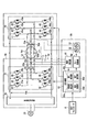
- the compressor 1 is a closed type compressor in which the motor 1M shown in FIG. 2 is housed in a closed case together with a compression unit as a drive motor.
- the motor 1M is a so-called open-winding motor (Open-Windings Motor) that is a three-phase permanent magnet synchronous motor and has a plurality of phase windings Lu, Lv, and Lw that are not connected to each other.
- the phase windings Lu, Lv, and Lw are configured by winding a large number of small-diameter copper wires at a high density so as to improve efficiency in a low rotation speed range (also referred to as a low / medium rotation speed range).
- the motor drive device 9 of the outdoor units A1 to A3 includes the drive circuit 9a and the controller 9b shown in FIG.
- the drive circuit 9a includes a DC power supply unit 55 that full-wave rectifies and smoothes and outputs the AC voltage of the three-phase AC power supply 50, the output end of the DC power supply unit 55, and the phase winding Lu, Lv of the open winding motor 1M.
- the inverter also referred to as the first inverter or master inverter
- the inverter 30 controls the energization between one end of Lw, the output end of the DC power supply unit 55, and the phase winding Lu, Lv, Lw of the open winding motor 1M.
- inverter 40 also referred to as a second inverter or a slave inverter 40 that controls the energization between the ends.
- a common power supply system is adopted in which the DC power supply 55 is a common DC power supply for the inverters 30 and 40.
- the inverter 30 connects the switching elements, for example, the IGBTs 31 and 32 in series, and connects the IGBTs 33 and 34 in series to the U-phase series circuit in which the interconnection points of the IGBTs 31 and 32 are connected to one end of the phase winding Lu of the open winding motor 1M.
- a V-phase series circuit in which the interconnection points of the IGBTs 33 and 34 are connected to one end of the phase winding Lv of the open winding motor 1M, the IGBTs 35 and 36 are connected in series, and the interconnection points of the IGBTs 35 and 36 are open windings.
- a W-phase series circuit connected to one end of the phase winding Lw of the motor 1M is included, and energization from the positive output end of the DC power supply 55 to one end of the phase windings Lu, Lv, Lw and the phase windings Lu, Lv,
- the energization from one end of Lw to the negative output end of the DC power supply 55 is controlled by switching the IGBTs 31 to 36.
- Regenerative diodes (also referred to as freewheel diodes) 31a to 36a are connected in antiparallel to the IGBTs 31 to 36.
- the inverter 40 connects the IGBTs 41 and 42 in series and connects the IGBTs 43 and 44 in series to the U-phase series circuit in which the interconnection points of the IGBTs 41 and 42 are connected to the other end of the phase winding Lu of the open winding motor 1M.
- the W-phase series circuit connected to the other end of the winding Lw is connected in parallel to each other, and the power supply from the positive output end of the DC power supply 55 to the other end of the phase windings Lu, Lv, Lw and the phase windings Lu, Lv ,
- the energization from the other end of Lw to the negative output end of the DC power supply 55 is controlled by switching the IGBTs 41 to 46.
- Regenerative diodes 41a to 46a are connected in antiparallel to the IGBTs 41 to 46.
- the inverter 30 is actually a peripheral of a main circuit formed by connecting the above three series circuits of U phase, V phase, and W phase in parallel to each other, and a drive circuit for driving the IGBTs 31 to 36 of the main circuit.
- the circuit is a so-called IPM (Intelligent Power Module) in which the circuit is housed in a single package.
- IPM Intelligent Power Module
- An IPM having the same configuration is used for the inverter 40.
- a normally open open / close contact (referred to as a relay contact) 51a of the mechanical relay 51 is connected between the other end of the phase winding Lu of the motor 1M and the other end of the phase winding Lv.
- a normally open open / close contact (referred to as a relay contact) 52a of the mechanical relay 52 is connected between the other end of the phase winding Lv of the motor 1M and the other end of the phase winding Lw.
- the relays 51 and 52 are controlled to be urged (energized on) and deenergized (energized off) in a state of being synchronized with each other by the controller 9b.
- the relay contacts 51a and 52a are closed, the other ends of the phase windings Lu, Lv and Lw are interconnected, and the phase windings Lu, Lv and Lw are in a star connection state. ..
- the relay contacts 51a and 52a are opened, and the phase windings Lu, Lv and Lw are in a disconnected state, that is, an electrically separated open winding state.
- the relays 51 and 52 have an upper limit value, so-called rated energizing current, for the current flowing through the relay contacts 51a and 52a in order to maintain the proper operation. If an overcurrent exceeding the rated energizing current flows through the relay contacts 51a and 52a, there is a high possibility that the relays 51 and 52 will fail. Since the relays 51 and 52 having a large rated current can be increased in size and expensive, it is desirable to use a relay having a small rated current if possible. Further, the number of times the relay contacts 51a and 52a are opened and closed greatly affects the life of the relays 51 and 52. That is, if the number of times the relay contacts 51a and 52a are opened and closed increases, the relays 51 and 52 reach the end of their service life and fail.
- Current sensors 53u, 53v, 53w are arranged on three energizing lines between the inverter 30 and one end of the phase winding Lu, Lv, Lw, and the output signals of these current sensors 53u, 53v, 53w are sent to the controller 9b. ..
- the current sensors 53u, 53v, 53w detect currents (referred to as motor currents) Iu, Iv, Iw flowing in the phase windings Lu, Lv, Lw.
- the controller 9b estimates the rotation speed of the motor 1M from the motor current I in the star connection mode described later, and switches the inverter 30 independently so that the estimated rotation speed becomes the target rotation speed according to the command from the outdoor controller 8.
- the sensorless vector control to be controlled is executed, and the sensorless vector control in the open winding mode that controls the switching of the inverters 30 and 40 so that the estimated rotation speed becomes the target rotation speed in the open winding mode described later is executed. It includes a main control unit 60, a current detection unit 61, a relay drive unit 62, a display unit 63, relays 51 and 52, etc., which are the core of control.
- the current detection unit 61 detects the instantaneous values of the motor currents Iu, Iv, and Iw detected by the current sensors 53u, 53v, and 53w.
- the instantaneous values of the motor currents Iu, Iv, and Iw are called the motor currents I.
- the relay drive unit 62 urges and deenergizes the relays 51 and 52 in response to a command from the main control unit 60.
- the main control unit 60 is composed of a microcomputer and its peripheral circuits, and controls switching of relay contacts 51a and 52a and switching of inverters 30 and 40 according to a command from the outdoor controller 8 and a detection result of the current detection unit 62. do.
- the main control unit 60 has an open winding mode and a relay contact in which the other ends of the phase windings Lu, Lv, and Lw are disconnected by opening the relay contacts 51a and 52a, and the inverters 30 and 40 are switched in conjunction with each other.
- the star connection mode in which the other ends of the phase windings Lu, Lv, and Lw are interconnected by closing the 51a and 52a to switch the inverter 30 independently is switched according to at least the value of the motor current I.
- the main functions include a rotation speed detection unit 60a and first, second and third control units 60b to 60d.
- the rotation speed detection unit 60a is based on the switching state of the inverters 30 and 40 and the motor current I of any one of the motor currents I of the phase windings Lu, Lv, and Lw, and the rotation speed (speed) N of the motor 1M. Is detected (estimated).
- the rotation speed N of the motor 1M is referred to as a motor rotation speed N.
- the first control unit 60b sets the open winding mode when starting the motor 1M, controls the switching of the inverters 30 and 40 so that the motor rotation speed N rises to a predetermined value in the high rotation speed range, and rotates the motor.
- the inverter so that the motor rotation speed N keeps the above-mentioned predetermined value for a predetermined time of about 1 minute. Controls switching between 30 and 40.
- the second control unit 60c is in the open winding mode so that the motor rotation speed N becomes the target rotation speed (target speed) Nt corresponding to the ability instructed by the outdoor controller 8. Controls the switching of the inverters 30 and 40.
- the second control unit 60c stores in the internal memory a second threshold value I2 that is the same as or slightly smaller than the rated current of the relays 51 and 52, and a first threshold value I1 that is smaller than the second threshold value I2.
- the following controls (1) to (3) are executed based on the threshold values I1 and I2.
- the peak value of the motor current I is lower than the second threshold value I2
- the motor rotation speed N rises to a high speed range of the second set value N2 or more, and the state is t2s for the second predetermined time. If it continues for (for example, 1 minute), the relay contacts 51a and 52a are immediately opened to switch to the open winding mode while continuing the motor drive, and the inverter 30 is set so that the motor rotation speed N becomes the target rotation speed Nt. Controls 40 switching. That is, if the motor rotation speed N is in the high rotation speed range of the second set value N2 or more, the high level voltage required for driving the motor can be obtained in the open winding mode in which the two inverters 30 and 40 are operated.
- the second predetermined time t2s waits for switching from the star connection mode to the open winding mode.
- the relay contacts 51a and 52a are closed and switched to the star connection mode while continuing the motor drive, and the inverter 30 is switched so that the motor rotation speed N becomes the target rotation speed Nt. To control. That is, if the peak value of the motor current I is continuously within the first threshold value I1 or less for the first predetermined time t1s or more, even if the star connection mode for closing the relay contacts 51a and 52a is set.
- the first threshold I1 which is the criterion for switching from the open winding mode to the star connection mode is set lower than the second threshold I2 which is the criterion for switching from the star connection mode to the open winding mode.
- This is due to the influence of the magnitude of the field component current (d-axis current) converted to the field axis (d-axis) coordinates on the rotor axis in the motor 1M when switching from the open winding mode to the star connection mode. Therefore, even if the motor is driven at the same motor rotation speed N, the motor current I is larger in the star connection mode than in the open winding mode.
- the peak value of the motor current I immediately rises to the second threshold value I2 after switching from the open winding mode to the star connection mode. It is possible to prevent the trouble of switching from the star connection mode to the open winding mode. Also in this respect, the number of times the relay contacts 51a and 52a are opened and closed can be reduced.
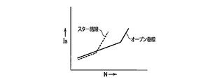
- FIG. 3 shows the relationship between the motor rotation speed N and the power supply current Is for each of the star connection mode and the open winding mode.
- the power supply current Is in the star connection mode is slightly lower than the power supply current Is in the open winding mode, and the efficiency is higher in the star connection mode.
- the power supply current Is in the star connection mode rises at a high speed, and the power supply current Is in the open winding mode rises slowly.
- the motor current I becomes high and the back electromotive force of the motor 1M becomes large, so that the motor 1M cannot be driven at a higher rotation speed.
- the mode switching condition shown in FIG. 5 for obtaining the highest possible efficiency within the range where the motor current I does not exceed the rated currents of the relays 51 and 52 is the controller 9b. It is stored in the second control unit 60c.
- the third control unit 60d sets the open winding mode regardless of the motor current I before the start of the defrosting operation, and the defrosting operation ends in the set state. Continue until you do. Specifically, the third control unit 60d defrosts when the outdoor controller 8 notifies that defrosting is required, that is, before the flow path of the four-way valve 2 is switched and the defrosting operation is started. At the time of preparation, the open winding mode is set regardless of the motor current I, and the inverters 30 and 40 are set so that the motor rotation speed N becomes the target rotation speed Nt for defrosting operation according to the command from the outdoor controller 8. Switching is controlled, and the set state of the open winding mode regardless of the motor current I is continued until the outdoor controller 8 notifies the end of the defrosting operation.
- the controller 9b When an operation start command is received from the outdoor controller 8 (YES in S1), the controller 9b initializes the time counts t1 and t2 to “0” (S2), respectively (S2), and opens the relay contacts 51a and 52a to perform phase winding.
- the open winding mode for switching the inverters 30 and 40 is set with the other ends of the wires Lu, Lv, and Lw disconnected (S3).
- the normally open relay contacts 51a and 52a are originally in the open state due to the deenergization (energization off) of the relays 51 and 52, and the phase windings Lu, Lv and Lw are disconnected from each other. Therefore, the open winding mode can be set without requiring the operation of the relay contacts 51a and 52a.
- the controller 9b sets a target rotation speed Nt corresponding to the capacity instructed by the outdoor controller 8 (S4), and the inverter 30 so that the motor rotation speed N becomes the target rotation speed Nt. , 40 switching is controlled (S5). As a result, the motor 1M is started.
- the setting of the target rotation speed Nt and the switching control at the time of start-up include a control in which the motor rotation speed N is raised to a predetermined value in the high rotation speed range and the state is maintained for a predetermined time of about 1 minute.
- a part of the current path formed in the open winding mode is shown by a broken line in FIG.
- the IGBT 31 of the inverter 30 is turned on and the IGBT 42 of the inverter 40 is repeatedly turned on and off, and the IGBTs 43 and 45 of the inverter 40 are both turned on and the IGBTs 34 and 36 of the inverter 30 are repeatedly turned on and off in synchronization with each other.
- a current flows from the positive output end of the DC power supply 55 through the IGBT 31 to the phase winding Lu, and the current passing through the phase winding Lu passes through the IGBT 42 to the negative of the DC power supply 55.
- a current flows from the positive output end of the DC power supply 55 through the IGBTs 43 and 45 to the phase windings Lv and Lw, and the current passing through the phase windings Lv and Lw passes through the IGBTs 34 and 36. It flows to the negative output end of the DC power supply 55.
- the IGBT 33 of the inverter 30 is turned on and the IGBT 44 of the inverter 40 is repeatedly turned on and off, and the IGBTs 41 and 45 of the inverter 40 are both turned on and the IGBTs 32 and 36 of the inverter 30 are repeatedly turned on and off in synchronization with each other. ..
- a current flows from the positive output end of the DC power supply 55 through the IGBT 33 to the phase winding Lv, and the current passing through the phase winding Lv flows through the IGBT 44 to the negative output end of the DC power supply 55.
- a current flows from the positive output end of the DC power supply 55 through the IGBTs 41 and 45 to the phase windings Lu and Lw, and the current passing through the phase windings Lu and Lw passes through the IGBTs 32 and 36 and outputs to the negative side of the DC power supply 55. It flows to the edge.
- the IGBT 35 of the inverter 30 is turned on and the IGBT 46 of the inverter 40 is repeatedly turned on and off, and the IGBTs 41 and 43 of the inverter 40 are both turned on and the IGBTs 32 and 34 of the inverter 30 are repeatedly turned on and off in synchronization with each other. ..
- a current flows from the positive output end of the DC power supply 55 through the IGBT 35 to the phase winding Lw, and the current passing through the phase winding Lw flows through the IGBT 46 to the negative output end of the DC power supply 55.
- the open winding mode in which the relays 51 and 52 are not urged and the relay contacts 51a and 52a are left open is set from the beginning, and the rotation speed N of the motor 1M is set to the high rotation speed range.
- the star connection mode that urges the relays 51 and 52 to close the relay contacts 51a and 52a is set in the low rotation speed range and then shifts to the open winding mode in the high rotation speed range. Therefore, the number of operations of the relay contacts 51a and 52a can be surely reduced by once. That is, it is possible to exhibit sufficient air conditioning capacity capable of dealing with an unstable high air conditioning load while suppressing the number of operations of the relay contacts 51a and 52a to be small.
- the controller 9b confirms whether the outdoor controller 8 notifies that defrosting is required (S6). If there is no notification that defrosting is required (NO in S6), the controller 9b is currently set to the open winding mode (YES in S10), so the peak value of the motor current I falls below the first threshold value I1. If (YES in S11) and the motor rotation speed N has dropped below the set value N1 (YES in S12), the time count t1 is started (S13), and the time count t1 and the predetermined time (20 minutes) are started. ) Compare with t1s (S15).
- the controller 9b While the time count t1 is less than the predetermined time t1s (NO in S15), the controller 9b confirms the operation stop command from the outdoor controller 8 (S25). If there is no operation stop command (NO in S25), the controller 9b returns to the above S4 and sets the target rotation speed Nt (S4), and the inverters 30 and 40 so that the motor rotation speed N becomes the target rotation speed Nt. Control switching (S5). Subsequently, the controller 9b repeats the determination from the above S10 unless there is a notification of the need for defrosting (NO in S6).
- the controller 9b clears the time count t1 to “0” (S14) and compares the time count t1 with the predetermined time t1s. (S15).
- the controller 9b switches from the conventional open winding mode to the star connection mode (S16), and Clear the time count t1 to "0" (S17). Then, if there is no operation stop command (NO in S25), the controller 9b returns to the above S4 and sets the target rotation speed Nt (S4), so that the motor rotation speed N becomes the target rotation speed Nt of the inverter 30. Control switching (S5).
- the controller 9b is notified that defrosting is required (NO in S6), the peak value of the motor current I is the second threshold value I2 because the star connection mode is currently set (NO in S10).
- the motor rotation speed N is equal to or more than the set value N2 (S19).
- the controller 9b starts the time count t2 (S20) and compares the time count t2 with the predetermined time (1 minute) t2s (S22). ..
- the controller 9b While the time count t1 is less than the predetermined time t1s (NO in S22), the controller 9b returns to the above S4 to set the target rotation speed Nt (S4) unless there is an operation stop command (NO in S25), and the motor The switching of the inverter 30 is controlled so that the rotation speed N becomes the target rotation speed Nt (S5). Subsequently, the controller 9b repeats the determination from the above S10 unless there is a notification of the need for defrosting (NO in S6).
- the controller 9b switches from the conventional star connection mode to the open winding mode (YES in S20). S23) and clear the time count t2 to "0" (S24).
- the controller 9b returns to the above S4 and sets the target rotation speed Nt (S4), so that the motor rotation speed N becomes the target rotation speed Nt. Controls the switching of 40 (S5). Subsequently, the controller 9b repeats the determination from the above S10 unless there is a notification of the need for defrosting (NO in S6).
- the controller 9b clears the time count t1 to "0" (S21) and compares the time count t1 with the predetermined time t1s (S22).
- the controller 9b forcibly sets the open winding mode regardless of the motor current I (S7), and the motor rotation speed N is outdoors.
- the switching of the inverters 30 and 40 is controlled so that the target rotation speed Nt for the defrosting operation according to the command from the controller 8 is obtained (S8).
- the controller 9b confirms the end notification of the defrosting operation from the outdoor controller 8 (S9). If there is no end notification (NO in S9), the controller 9b repeats the switching control in S8 (S8).
- FIG. 7 shows an example of the change in the motor rotation speed N from the start of defrost preparation to the end of the defrost operation after the notification of the need for defrosting. Since the motor rotation speed N reaches the high rotation speed range during the defrosting operation where the load becomes large, by setting the open winding mode in advance before the start of the defrosting operation, stable and reliable defrosting operation can be performed. It will be possible.
- the mode is switched to the open winding mode.
- the current is applied to the relay contacts 51a and 52a in order to prioritize the prevention of overcurrent at the relay contacts 51a and 52a over the efficiency. Immediately switch to non-flowing open winding mode.
- the open winding mode and the star connection mode are switched by using the peak value of the instantaneous value as the motor current value I, but the open winding mode uses the effective value Ia instead of the peak value of the instantaneous value.
- the mode and the star connection mode may be switched.
- the open winding mode and the star connection mode are switched according to the rotation speed of the motor, but the d-axis current value and the inverter, which are the weakened field amount considered to be equal to the rotation speed of the motor.
- the PWM voltage output duty, the modulation rate, etc. of the above can be used instead of the motor rotation speed.
- the common power supply method in which the inverters 30 and 40 are connected to the same DC power supply 55 is adopted, but the same can be implemented in the power supply isolation method in which the inverters 30 and 40 are connected to different DC power supplies.
Landscapes
- Engineering & Computer Science (AREA)
- Power Engineering (AREA)
- Physics & Mathematics (AREA)
- Mechanical Engineering (AREA)
- Thermal Sciences (AREA)
- General Engineering & Computer Science (AREA)
- Chemical & Material Sciences (AREA)
- Combustion & Propulsion (AREA)
- Control Of Ac Motors In General (AREA)
Abstract
モータ駆動装置は、機械式のリレーの開放接点の開放によりモータの各相巻線の他端を非接続状態とし第1および第2インバータを互いに連係してスイッチングするオープン巻線モード、及び上記リレーの開放接点の閉成により上記各相巻線の他端を相互接続して第1インバータをスイッチングするスター結線モードを、モータに流れる電流の値に応じて切替える。
Description
本発明は、互いに非接続状態の複数の相巻線を有するモータを駆動するモータ駆動装置およびそのモータ駆動装置を備えた冷凍サイクル装置に関する。
空気調和機等の冷凍サイクル装置に搭載される圧縮機の駆動モータとして、複数の相巻線を有する永久磁石同期モータが使用される。また、永久磁石同期モータ(DCブラシレスモータともいう)の一例として、複数の相巻線を互いに非接続状態とした構成のオープン巻線モータ(Open-Windings Motor)が知られている。
このオープン巻線モータ(モータと略称する)を駆動するモータ駆動装置は、モータの各相巻線の一端への通電を制御する第1インバータ、モータの各相巻線の他端への通電を制御する第2インバータ、各相巻線の他端の相互間に接続される開閉器を備え、この開閉器の閉成により各相巻線をスター結線(星形結線ともいう)して第1インバータを単独でスイッチングするスター結線モード、及び開閉器の開放により各相巻線を非接続状態として第1および第2インバータを互いに連係してスイッチングするオープン巻線モードを、選択的に設定する。オープン巻線モードの設定によりモータを高回転数で駆動することができ、低回転数域でのスター結線モードの設定によりモータを高効率で駆動することができ、よって高回転数から低回転数まで幅広い運転範囲にわたりモータをできるだけ効率よく駆動することが可能となる。モータの運転範囲の拡大とモータ駆動装置の効率向上を両立させている。
スター結線モードとオープン巻線モードを切替える開閉器として、例えば機械的な開閉接点を有する機械式のリレーが使用される。このリレーには、適正な動作を保証するため、開閉接点を流れる電流についての上限値がある。この上限値は、一般的に定格通電電流や接点定格電流と呼ばれる(以下、定格通電電流という)。この定格通電電流を超える過電流がリレーの開閉接点に流れ続けると、リレーが故障する恐れがある。また、機械式のリレーには作動の回数に応じた寿命がある。この寿命はスター結線モードとオープン巻線モードの切替え回数が多いほど短くなる。
本発明の実施形態の目的は、過電流がリレーの開閉接点に流れる不具合を防ぐことができ、しかもリレーの作動回数をできるだけ少なくすることができ、これによりリレーの寿命向上が図れる冷凍サイクル装置を提供することである。
請求項1のモータ駆動装置は、互いに非接続状態の複数の相巻線を有するモータと;前記各相巻線の一端への通電を制御する第1インバータと;前記各相巻線の他端への通電を制御する第2インバータと;前記各相巻線の他端の相互間に接続された開閉接点を有するリレーと;このリレーの開放により前記各相巻線の他端を非接続状態とし前記第1および第2インバータを互いに連係してスイッチングするオープン巻線モード、及び前記リレーの閉成により前記各相巻線の他端を相互接続して前記第1インバータをスイッチングするスター結線モードを、前記モータに流れる電流の値に応じて切替えるコントローラと;を備える。
以下、一実施形態の冷凍サイクル装置について図面を参照しながら説明する。冷凍サイクル装置の例として、複数の室外機および複数の室内機を互いに並列接続したいわゆるマルチタイプの空気調和機について説明する。空気調和機に限らず、ヒートポンプ式チラーユニットや冷凍機など他の冷凍サイクル装置への適用も可能である。
図1に示すように、室外機Aに液側管C1およびガス側管C2を介して、例えば2台の室内機B1,B2が互いに並列状態で接続されている。そして、室外機Aおよび室内機B1,B2の相互間にデータ伝送用および制御用の信号ラインEが接続されている。これら室外機Aおよび室内機B1,B2の接続により、冷暖房を行うマルチタイプの冷凍サイクル装置が構成される。この冷凍サイクル装置では、室外機Aが全体制御用の親機として機能し、室内機B1,B2が親機からの指示に従って動作する子機として機能する。
室外機Aは、圧縮機1、四方弁2、室外熱交換器3、膨張弁(減圧器)4、アキュームレータ5、室外ファン6、室外温度センサ7、熱交換器温度センサTe、室外コントローラ8、および本実施形態のモータ駆動装置9を備える。冷房運転時、実線矢印で示すように、室内機B1,B2からガス側管C2に流れるガス冷媒が四方弁2およびアキュームレータ5を通って圧縮機1に吸込まれ、その圧縮機1で圧縮され吐出されるガス冷媒が四方弁2を通って室外熱交換器3(凝縮器)に流れ、その室外熱交換器3で外気と熱交換して凝縮する冷媒が膨張弁4および液側管C1を通って室内機B1,B2へ流れる。暖房運転時、四方弁2の流路が切替えられることにより、室内機B1,B2から液側管C1に流れる液冷媒が膨張弁4を通って室外熱交換器3(蒸発器)に流れ、その室外熱交換器3で外気と熱交換して気化する冷媒が四方弁2およびアキュームレータ5を通って圧縮機1に吸込まれ、その圧縮機1で圧縮され吐出されるガス冷媒が四方弁2およびガス側管C2を通って室内機B1,B2へ流れる。
なお、暖房運転時、蒸発器として機能する室外熱交換器3の表面に徐々に霜が付着しそのままでは室外熱交換器3の熱交換量が減少する。対策として、室外コントローラ8は、室外熱交換器3の温度を熱交換器温度センサTeで検知し、その検知温度から室外熱交換器3の着霜量を監視し、着霜量が増えた場合は室外熱交換器3の除霜が必要であるとの判断の下に、モータ回転数Nを下降させる除霜準備に入り、モータ回転数Nが所定値に低下したところで四方弁2の流路を除霜用に切替えつつモータ回転数Nを高回転数域まで上昇させる除霜運転を開始し、室外熱交換器3に付いた霜を冷媒の熱で除去する。そして、室外コントローラ8は、熱交換器温度センサTeの検知温度に基づいて室外熱交換器3の着霜状態を監視し、着霜がなくなった時点でモータ回転数Nを下降させ、モータ回転数Nが所定値に低下したところで四方弁2の流路を元の暖房用に戻して除霜運転を終了する。また、室外コントローラ8は、除霜が必要と判断した時点で除霜要の旨をモータ駆動装置9に通知し、この通知に伴い上記除霜準備に入るとともに、除霜運転を終了した時点でその旨をモータ駆動装置9に通知する。
室内機B1,B2は、それぞれ、流量調整弁11、室内熱交換器12、室内ファン13、室内温度センサ14、および室内コントローラ15を含む。冷房運転時、実線矢印で示すように、室外機Aから液側管C1に流れる液冷媒が流量調整弁11を通って室内熱交換器(蒸発器)12に流れ、その室内熱交換器12で室内空気と熱交換して気化する冷媒がガス側管C2を通って室外機Aへ戻る。暖房運転時、室外機Aからガス側管C2に流れるガス冷媒が室内熱交換器(凝縮器)12に流れ、その室内熱交換器12で室内空気と熱交換して凝縮する冷媒が液側管C1を通って室外機Aへ戻る。流量調整弁11は、供給される駆動電圧パルスの数に応じて開度が全閉から全開まで連続的に変化するパルスモータバルブ(PMV)である。室内ファン13は、室内空気を吸込んで室内熱交換器12に送る。室内温度センサ14は、室内ファン13により吸込まれる室内空気の流路に配置され、その室内空気の温度Taを検知する。室内コントローラ15は、室内温度センサ14の検知温度Taと予め設定される室内設定温度Tsとの差ΔTaを空調負荷として検出し、その空調負荷ΔTaに応じて流量調整弁11の開度を制御するとともに、その空調負荷ΔTaを信号ラインEにより室外コントローラ8に通知する。
室外コントローラ8は、室内機B1,B2から通知される空調負荷ΔTaの合計負荷に対応する能力を室外機Aが発揮できるよう圧縮機1や室外ファン6の回転数等を制御する。
圧縮機1は、図2に示すモータ1Mを駆動モータとして圧縮部と共に密閉ケースに収容した密閉型圧縮機である。モータ1Mは、三相永久磁石同期モータであって、かつ互いに非接続状態の複数の相巻線Lu,Lv,Lwを有するいわゆるオープン巻線モータ(Open-Windings Motor)である。相巻線Lu,Lv,Lwは、低回転数域(低・中回転数域ともいう)で効率が向上するよう、細径の銅線を高い密度で多く巻回して構成される。
室外機A1~A3のモータ駆動装置9は、図2に示す駆動回路9aおよびコントローラ9bを含む。駆動回路9aは、三相交流電源50の交流電圧を全波整流して平滑し出力する直流電源部55、この直流電源部55の出力端とオープン巻線モータ1Mの相巻線Lu,Lv,Lwの一端との間の通電を制御するインバータ(第1インバータまたはマスタインバータともいう)30、および上記直流電源部55の出力端とオープン巻線モータ1Mの相巻線Lu,Lv,Lwの他端との間の通電を制御するインバータ(第2インバータまたはスレーブインバータともいう)40を含む。直流電源55をインバータ30,40の共通の直流電源とする電源共通方式を採用している。
インバータ30は、スイッチング素子たとえばIGBT31,32を直列接続しそのIGBT31,32の相互接続点がオープン巻線モータ1Mの相巻線Luの一端に接続されるU相直列回路、IGBT33,34を直列接続しそのIGBT33,34の相互接続点がオープン巻線モータ1Mの相巻線Lvの一端に接続されるV相直列回路、IGBT35,36を直列接続しそのIGBT35,36の相互接続点がオープン巻線モータ1Mの相巻線Lwの一端に接続されるW相直列回路を含み、直流電源55の正側出力端から相巻線Lu,Lv,Lwの一端への通電および相巻線Lu,Lv,Lwの一端から直流電源55の負側出力端への通電をIGBT31~36のスイッチングにより制御する。IGBT31~36には、回生用ダイオード(フリー・ホイール・ダイオードともいう)31a~36aが逆並列接続されている。
インバータ40は、IGBT41,42を直列接続しそのIGBT41,42の相互接続点がオープン巻線モータ1Mの相巻線Luの他端に接続されるU相直列回路、IGBT43,44を直列接続しそのIGBT43,44の相互接続点がモータ1Mの相巻線Lvの他端に接続されるV相直列回路、IGBT45,46を直列接続しそのIGBT45,46の相互接続点がオープン巻線モータ1Mの相巻線Lwの他端に接続されるW相直列回路を互いに並列接続し、直流電源55の正側出力端から相巻線Lu,Lv,Lwの他端への通電および相巻線Lu,Lv,Lwの他端から直流電源55の負側出力端への通電をIGBT41~46のスイッチングにより制御する。IGBT41~46には、回生用ダイオード41a~46aが逆並列接続されている。
なお、インバータ30は、実際には、U相・V相・W相の上記3つの直列回路を互いに並列接続してなる主回路と、この主回路のIGBT31~36を駆動する駆動回路などの周辺回路とを、単一のパッケージに収納したモジュールいわゆるIPM(Intelligent Power Module)である。インバータ40も、同様の構成のIPMが使用される。
モータ1Mの相巻線Luの他端と相巻線Lvの他端との相互間に、機械式のリレー51の常開形の開閉接点(リレー接点という)51aが接続されている。モータ1Mの相巻線Lvの他端と相巻線Lwの他端との相互間に、機械式のリレー52の常開形の開閉接点(リレー接点という)52aが接続されている。リレー51,52は、コントローラ9bにより、互いに同期した状態で付勢(通電オン)と消勢(通電オフ)が制御される。リレー51,52が付勢されるとリレー接点51a,52aが閉成し、相巻線Lu,Lv,Lwの他端が相互接続されて相巻線Lu,Lv,Lwがスター結線状態となる。リレー51,52が消勢されるとリレー接点51a,52aが開放し、相巻線Lu,Lv,Lwが非接続状態つまり電気的に分離したオープン巻線状態となる。
リレー51,52には、その適正な動作を保つため、リレー接点51a,52aを流れる電流についての上限値いわゆる定格通電電流がある。定格通電電流を超える過電流がリレー接点51a,52aに流れると、リレー51,52が故障する可能性が高くなる。定格通電電流の大きなリレー51,52はサイズが大きくなるとともに高価となるため、できれば定格通電電流の小さなリレーを使うことが望ましい。また、リレー接点51a,52aの開閉回数がリレー51,52の寿命に大きく影響する。すなわち、リレー接点51a,52aの開閉回数が多くなると、リレー51,52が寿命を迎えて故障してしまう。
インバータ30と相巻線Lu,Lv,Lwの一端との間の3つの通電ラインに電流センサ53u,53v,53wが配置され、これら電流センサ53u,53v,53wの出力信号がコントローラ9bに送られる。電流センサ53u,53v,53wは、相巻線Lu,Lv,Lwに流れる電流(モータ電流という)Iu,Iv,Iwを検知する。
コントローラ9bは、後述のスター結線モード時はモータ電流Iからモータ1Mの回転数を推定しその推定回転数が室外コントローラ8からの指令に応じた目標回転数となるようインバータ30の単独のスイッチングを制御するセンサレス・ベクトル制御を実行し、後述のオープン巻線モード時は上記推定回転数が目標回転数となるようインバータ30,40のスイッチングを制御するオープン巻線モードのセンサレス・ベクトル制御を実行するもので、制御の中枢となる主制御部60、電流検出部61、リレー駆動部62、表示部63、リレー51,52などを含む。電流検出部61は、電流センサ53u,53v,53wで検知されるモータ電流Iu,Iv,Iwのそれぞれの瞬時値を検出する。モータ電流Iu,Iv,Iwのそれぞれ瞬時値のことをモータ電流Iという。リレー駆動部62は、主制御部60からの指令に応じてリレー51,52を付勢および消勢する。主制御部60は、マイクロコンピュータおよびその周辺回路により構成され、室外コントローラ8からの指令および電流検出部62の検出結果などに応じてリレー接点51a,52aの開閉およびインバータ30,40のスイッチングを制御する。
とくに、主制御部60は、リレー接点51a,52aの開放により相巻線Lu,Lv,Lwの他端を非接続状態としインバータ30,40を互いに連係してスイッチングするオープン巻線モード及びリレー接点51a,52aの閉成により相巻線Lu,Lv,Lwの他端を相互接続してインバータ30を単独でスイッチングするスター結線モードを少なくともモータ電流Iの値に応じて切替えるもので、この切替えに関する主要な機能として回転数検出部60aおよび第1,第2,第3制御部60b~60dを含む。
回転数検出部60aは、インバータ30,40のスイッチング状態、および相巻線Lu,Lv,Lwの各モータ電流Iのうちいずれか1つのモータ電流Iに基づき、モータ1Mの回転数(速度)Nを検出(推定)する。以下、モータ1Mの回転数Nのことをモータ回転数Nという。
第1制御部60bは、モータ1Mの起動に際し、オープン巻線モードを設定し、モータ回転数Nが高回転数域の所定値まで上昇するようインバータ30,40のスイッチングを制御するとともに、モータ回転数Nが上記所定値まで上昇したところで、一旦、圧縮機1中の潤滑油の油面の安定性を確保するため、モータ回転数Nが1分程度の所定時間にわたり上記所定値を保つようインバータ30,40のスイッチングを制御する。
第2制御部60cは、第1制御部60bの制御に続き、モータ回転数Nが室外コントローラ8から指示される能力に対応する目標回転数(目標速度)Ntとなるようオープン巻線モードでのインバータ30,40のスイッチングを制御する。とくに、第2制御部60cは、リレー51,52の定格通電電流と同じまたはそれよりわずかに小さい第2閾値I2、およびその第2閾値I2より小さい第1閾値I1を内部メモリに記憶しており、この閾値I1,I2に基づいて次の(1)~(3)の制御を実行する。
(1)スター結線モード時、モータ電流Iのピーク値が第2閾値I2まで上昇した場合、モータ回転数Nにかかわらず、モータ駆動を続けながら直ちにリレー接点51a,52aを開放してオープン巻線モードに切替え、切替えが完了したところでモータ回転数Nが目標回転数Ntとなるようインバータ30,40のスイッチングを制御する。すなわち、モータ電流Iのピーク値が閾値I2まで上昇した際にリレー接点51a,52aが閉成した状態のスター結線モードのままではリレー接点51a,52aに過電流が流れる可能性があるので、モータ回転数Nにかかわらず直ちにオープン巻線モードに切替える。リレー接点51a,52aを開放するオープン巻線モードであれば、そもそもリレー接点51a,52aに電流が流れないので、モータ1Mの駆動を続けながら、過電流によるリレー51,52の故障を防ぐことができる。
(2)スター結線モード時、モータ電流Iのピーク値が第2閾値I2よりも低く、モータ回転数Nが第2設定値N2以上の高速度域に上昇してその状態が第2所定時間t2s(例えば1分間)にわたり継続した場合、上記同様、モータ駆動を続けながら直ちにリレー接点51a,52aを開放してオープン巻線モードに切替え、モータ回転数Nが目標回転数Ntとなるようインバータ30,40のスイッチングを制御する。すなわち、モータ回転数Nが第2設定値N2以上の高回転数域にあれば2つのインバータ30,40を動作させるオープン巻線モードの方がモータ駆動に必要な高レベルの電圧を得られて効率もよい点を考慮し、オープン巻線モードに切替える。ただし、空調負荷等の変動に伴いモータ回転数Nおよびモータ電流Iが頻繁に変動するおそれがあるので、モータ回転数Nおよびモータ電流Iに変動があってもその変動が収束するまでに要する少なくとも第2所定時間t2sは、スター結線モードからオープン巻線モードへの切替えを待つようにしている。これにより、リレー接点51a,52aの頻繁な開閉を防ぐことができ、ひいてはリレー接点51a,52aの開閉回数を減少させることができ、リレー51,52の長寿命化が図れる。
(3)オープン巻線モード時、モータ電流Iのピーク値が第1閾値I1以下である状態が第1所定時間(例えば20分間)t1sにわたり継続した場合、モータ駆動を続けながらリレー接点51a,52aを閉成してスター結線モードに切替え、切替えが完了したところでモータ回転数Nが目標回転数Ntとなるようインバータ30のスイッチングを制御する(インバータ40のスイッチングは停止)。具体的には、オープン巻線モード時、モータ電流Iのピーク値が第1閾値I1以下である状態かつモータ回転数Nが第2設定値N2より低い第1設定値以下の低回転数域に存する状態が第1所定時間t1sにわたり継続した場合、モータ駆動を続けながらリレー接点51a,52aを閉成してスター結線モードに切替え、モータ回転数Nが目標回転数Ntとなるようインバータ30のスイッチングを制御する。すなわち、モータ電流Iのピーク値が第1閾値I1以下の状態に第1所定時間t1s以上にわたり継続的に収まる状態にあれば、リレー接点51a,52aを閉成するスター結線モードを設定してもリレー接点51a,52aに過電流が流れる心配がない点、またモータ回転数Nが第1設定値N1以下の低回転数域に第1所定時間t1sにわたり継続的に収まる状態にあれば、1つのインバータ30のみ動作させる高効率のスター結線モードでもモータ駆動に十分なレベルの電圧が得られる点を考慮し、スター結線モードに切替える。
なお、オープン巻線モードからスター結線モードへ切替えの判定の基準である第1閾値I1をスター結線モードからオープン巻線モードへの切替えの判定基準である第2閾値I2よりも低く設定しているのは、オープン巻線モードからスター結線モードに切替えた場合、モータ1Mにおけるロータ軸上の界磁軸(d軸)座標に換算された界磁成分電流(d軸電流)の大きさなどの影響から、同じモータ回転数Nで駆動していてもスター結線モードの方がオープン巻線モード時よりもモータ電流Iが大きくなることに対処している。つまり、第1閾値I1を第2閾値I2よりも低く設定しておくことで、オープン巻線モードからスター結線モードに切替えた後、モータ電流Iのピーク値がすぐに第2閾値I2まで上昇してスター結線モードからオープン巻線モードに切替わる不具合を未然に防ぐことができる。この点でも、リレー接点51a,52aの開閉回数を減少させることができる。
図3は、モータ回転数Nと電源電流Isとの関係をスター結線モードとオープン巻線モードのモード別に示している。モータ回転数Nが低いときはスター結線モード時の電源電流Isの方がオープン巻線モード時の電源電流Isよりも少し低くなりスター結線モード時の方が効率が良い。モータ回転数Nがそこから上昇するのに伴い、スター結線モード時の電源電流Isは速い速度で上昇し、オープン巻線モード時の電源電流Isはゆっくり上昇する。この際、スター結線モード時はモータ電流Iが高くなってしまうとともに、モータ1Mの逆起電力が大きくなってしまい、さらなる高回転数でモータ1Mを駆動することができなくなる。
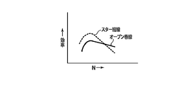
図4は、モータ回転数Nと効率との関係をスター結線モードとオープン巻線モードのモード別に示している。モータ回転数Nが低いときはスター結線モードの方がオープン巻線モードよりも効率が高く、モータ回転数Nが高くなるとオープン巻線モードの方がスター結線モードよりも効率が高くなる。
図4は、モータ回転数Nと効率との関係をスター結線モードとオープン巻線モードのモード別に示している。モータ回転数Nが低いときはスター結線モードの方がオープン巻線モードよりも効率が高く、モータ回転数Nが高くなるとオープン巻線モードの方がスター結線モードよりも効率が高くなる。
この図3および図4のモータ1Mの特性を考慮し、モータ電流Iがリレー51,52の定格通電電流を超えない範囲でできるだけ高い効率を得るための図5に示すモード切換条件がコントローラ9bの第2制御部60cに格納されている。
上記第3制御部60dは、室外コントローラ8による除霜運転の実行に際し、その除霜運転の開始前にモータ電流Iにかかわらずオープン巻線モードを設定し、その設定状態を除霜運転が終了するまで継続する。具体的には、第3制御部60dは、除霜要の旨の通知を室外コントローラ8から受けた時点、つまり四方弁2の流路が切替わって除霜運転が開始となる前の除霜準備の時点で、モータ電流Iにかかわらずオープン巻線モードを設定し、モータ回転数Nが室外コントローラ8からの指令に応じた除霜運転用の目標回転数Ntとなるようインバータ30,40のスイッチングを制御し、このモータ電流Iにかかわらないオープン巻線モードの設定状態を室外コントローラ8から除霜運転の終了通知を受けるまで継続する。
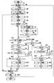
つぎに、コントローラ9bが実行する制御を図6のフローチャートを参照しながら説明する。フローチャート中のステップS1,S2…については単にS1,S2…と略称する。
[モータ1Mの起動時]
室外コントローラ8から運転開始指令を受けた場合(S1のYES)、コントローラ9bは、タイムカウントt1,t2をそれぞれ“0”に初期化するとともに(S2)、リレー接点51a,52aの開放により相巻線Lu,Lv,Lwの他端を非接続状態としてインバータ30,40をスイッチングするオープン巻線モードを設定する(S3)。モータ1Mの停止時はリレー51,52の消勢(通電オフ)により常開形のリレー接点51a,52aがもともと開放状態にあって、相巻線Lu,Lv,Lwが互いに非接続状態となっているので、リレー接点51a,52aの作動を要することなくオープン巻線モードを設定することができる。
室外コントローラ8から運転開始指令を受けた場合(S1のYES)、コントローラ9bは、タイムカウントt1,t2をそれぞれ“0”に初期化するとともに(S2)、リレー接点51a,52aの開放により相巻線Lu,Lv,Lwの他端を非接続状態としてインバータ30,40をスイッチングするオープン巻線モードを設定する(S3)。モータ1Mの停止時はリレー51,52の消勢(通電オフ)により常開形のリレー接点51a,52aがもともと開放状態にあって、相巻線Lu,Lv,Lwが互いに非接続状態となっているので、リレー接点51a,52aの作動を要することなくオープン巻線モードを設定することができる。
このオープン巻線モードの設定に伴い、コントローラ9bは、室外コントローラ8から指示される能力に見合う目標回転数Ntを設定し(S4)、モータ回転数Nがその目標回転数Ntとなるようインバータ30,40のスイッチングを制御する(S5)。これにより、モータ1Mが起動する。この起動時の目標回転数Ntの設定およびスイッチング制御は、モータ回転数Nを高回転数域の所定値まで上昇させてその状態を1分程度の所定時間にわたり保つ制御を含む。
オープン巻線モード時に形成される電流経路の一部を図2に破線で示す。まず、インバータ30のIGBT31がオンしてインバータ40のIGBT42がオン,オフを繰返すとともに、インバータ40のIGBT43,45が共にオンしてインバータ30のIGBT34,36が互いに同期してオン,オフを繰返す。これにより、破線矢印で示すように、直流電源55の正側出力端からIGBT31を通って相巻線Luに電流が流れ、その相巻線Luを経た電流がIGBT42を通って直流電源55の負側出力端に流れるとともに、直流電源55の正側出力端からIGBT43,45を通って相巻線Lv,Lwに電流が流れ、その相巻線Lv,Lwを経た電流がIGBT34,36を通って直流電源55の負側出力端に流れる。次に、インバータ30のIGBT33がオンしてインバータ40のIGBT44がオン,オフを繰返すとともに、インバータ40のIGBT41,45が共にオンしてインバータ30のIGBT32,36が互いに同期してオン,オフを繰返す。これにより、直流電源55の正側出力端からIGBT33を通って相巻線Lvに電流が流れ、その相巻線Lvを経た電流がIGBT44を通って直流電源55の負側出力端に流れるとともに、直流電源55の正側出力端からIGBT41,45を通って相巻線Lu,Lwに電流が流れ、その相巻線Lu,Lwを経た電流がIGBT32,36を通って直流電源55の負側出力端に流れる。次に、インバータ30のIGBT35がオンしてインバータ40のIGBT46がオン,オフを繰返すとともに、インバータ40のIGBT41,43が共にオンしてインバータ30のIGBT32,34が互いに同期してオン,オフを繰返す。これにより、直流電源55の正側出力端からIGBT35を通って相巻線Lwに電流が流れ、その相巻線Lwを経た電流がIGBT46を通って直流電源55の負側出力端に流れるとともに、直流電源55の正側出力端からIGBT41,43を通って相巻線Lu,Lvに電流が流れ、その相巻線Lu,Lvを経た電流がIGBT32,34を通って直流電源55の負側出力端に流れる。これら3パターンの電流経路が順に切替わることにより、モータ1Mのロータが回転する。
このオープン巻線モードの設定により、スター結線モード時の約√3倍の電圧を相巻線Lu,Lv,Lwに印加することができ、よって運転開始時の高空調負荷に対応する高回転数域へとモータ回転数Nを効率よく上昇させることが可能となる。とくに、空気調和装置の運転開始時は、空調負荷が高いだけでなく、室内ファン13が動き始めたばかりで新鮮な室内空気が室内温度センサ14にうまく流れないため室内温度検知が不安定な状態にあって、空調負荷を的確に捕らえることが難しい。このような運転開始時の状況では、リレー51,52を付勢せずリレー接点51a,52aを開放したままのオープン巻線モードを初めから設定してモータ1Mの回転数Nを高回転数域まで上昇させるほうが、リレー51,52を付勢してリレー接点51a,52aを閉成するスター結線モードを低回転数域で設定し、その後の高回転数域でオープン巻線モードに移行する場合よりも、リレー接点51a,52aの作動回数を確実に1回は少なくすることができる。つまり、リレー接点51a,52aの作動回数を少なく抑えながら、不安定な高空調負荷に対処し得る十分な空調能力を発揮することが可能となる。
[モータ1Mの起動後]
上記オープン巻線モードによるモータ1Mの起動に伴い、コントローラ9bは、室外コントローラ8から除霜要の通知があるか確認する(S6)。除霜要の通知がない場合(S6のNO)、コントローラ9bは、現時点でオープン巻線モードを設定しているので(S10のYES)、モータ電流Iのピーク値が第1閾値I1以下に収まっていて(S11のYES)、かつモータ回転数Nが設定値N1以下に下降していれば(S12のYES)、タイムカウントt1を開始し(S13)、そのタイムカウントt1と所定時間(20分間)t1sとを比較する(S15)。
上記オープン巻線モードによるモータ1Mの起動に伴い、コントローラ9bは、室外コントローラ8から除霜要の通知があるか確認する(S6)。除霜要の通知がない場合(S6のNO)、コントローラ9bは、現時点でオープン巻線モードを設定しているので(S10のYES)、モータ電流Iのピーク値が第1閾値I1以下に収まっていて(S11のYES)、かつモータ回転数Nが設定値N1以下に下降していれば(S12のYES)、タイムカウントt1を開始し(S13)、そのタイムカウントt1と所定時間(20分間)t1sとを比較する(S15)。
タイムカウントt1が所定時間t1sに満たない間(S15のNO)、コントローラ9bは、室外コントローラ8からの運転停止指令を確認する(S25)。運転停止指令がなければ(S25のNO)、コントローラ9bは、上記S4に戻って目標回転数Ntを設定し(S4)、モータ回転数Nがその目標回転数Ntとなるようインバータ30,40のスイッチングを制御する(S5)。続いて、コントローラ9bは、除霜要の通知がなければ(S6のNO)、上記S10からの判定を繰り返す。
上記S11の判定においてモータ電流Iのピーク値が第1閾値I1以下の領域から第1閾値I1超の領域に上昇した場合(S11のNO)、あるいは上記S11の判定においてモータ回転数Nが設定値N1以下の領域から設定値N1超の領域に上昇した場合(S12のNO)、コントローラ9bは、タイムカウントt1を“0”にクリアし(S14)、そのタイムカウントt1と所定時間t1sとを比較する(S15)。
上記S11の判定においてモータ電流Iのピーク値が第1閾値I1以下に収まったまま(S11のYES)、しかも上記S12の判定においてモータ回転数Nが設定値N1以下に下降したまま(S12のYES)、タイムカウントt1が続いてそのタイムカウントt1が所定時間t1sに達した場合(S13,S15のYES)、コントローラ9bは、これまでのオープン巻線モードからスター結線モードに切替え(S16)、かつタイムカウントt1を“0”にクリアする(S17)。そして、コントローラ9bは、運転停止指令がなければ(S25のNO)、上記S4に戻って目標回転数Ntを設定し(S4)、モータ回転数Nがその目標回転数Ntとなるようインバータ30のスイッチングを制御する(S5)。
続いて、コントローラ9bは、除霜要の通知がなければ(S6のNO)、現時点で設定しているのはスター結線モードなので(S10のNO)、モータ電流Iのピーク値が第2閾値I2未満であることを前提に(S18のNO)、モータ回転数Nが設定値N2以上であるか否かを判定する(S19)。モータ回転数Nが設定値N2以上の場合(S19のYES)、コントローラ9bは、タイムカウントt2を開始し(S20)、そのタイムカウントt2と所定時間(1分間)t2sとを比較する(S22)。
タイムカウントt1が所定時間t1sに満たない間(S22のNO)、コントローラ9bは、運転停止指令がなければ(S25のNO)、上記S4に戻って目標回転数Ntを設定し(S4)、モータ回転数Nがその目標回転数Ntとなるようインバータ30のスイッチングを制御する(S5)。続いて、コントローラ9bは、除霜要の通知がなければ(S6のNO)、上記S10からの判定を繰り返す。
上記S18の判定においてモータ電流Iのピーク値が第2閾値I2未満という前提条件が満たされたまま(S18のNO)、しかも上記S19の判定においてモータ回転数Nが設定値N2以上に上昇したまま(S19のYES)、タイムカウントt2が続いてそのタイムカウントt2が所定時間t2sに達した場合(S20,S22のYES)、コントローラ9bは、これまでのスター結線モードからオープン巻線モードに切替え(S23)、かつタイムカウントt2を“0”にクリアする(S24)。そして、コントローラ9bは、運転停止指令がなければ(S25のNO)、上記S4に戻って目標回転数Ntを設定し(S4)、モータ回転数Nがその目標回転数Ntとなるようインバータ30,40のスイッチングを制御する(S5)。続いて、コントローラ9bは、除霜要の通知がなければ(S6のNO)、上記S10からの判定を繰り返す。
上記S18の判定においてモータ電流Iのピーク値が第2閾値I2未満という前提条件が満たされたままでも(S18のNO)、上記S19の判定においてモータ回転数Nが設定値N2未満の領域に下降した場合(S19のNO)、コントローラ9bは、タイムカウントt1を“0”にクリアし(S21)、そのタイムカウントt1と所定時間t1sとを比較する(S22)。
ただし、上記S18の判定においてモータ電流Iのピーク値が第2閾値I2まで上昇すると(S18のYES)、リレー接点51a,52aに定格通電電流を超える過電流が流れ続けてしまう可能性があるので、コントローラ9bは、直ちに、スター結線モードからオープン巻線モードに切替える(S23)。リレー接点51a,52aを開放するオープン巻線モードではそもそもリレー接点51a,52aに電流が流れないので、過電流によるリレー51,52への悪影響を回避することができる。
上記S6の判定において、除霜要の通知がある場合(S6のYES)、コントローラ9bは、モータ電流Iにかかわらずオープン巻線モードを強制的に設定し(S7)、モータ回転数Nが室外コントローラ8からの指令に応じた除霜運転用の目標回転数Ntとなるようそのインバータ30,40のスイッチングを制御する(S8)。そして、コントローラ9bは、室外コントローラ8からの除霜運転の終了通知を確認する(S9)。終了通知がなければ(S9のNO)、コントローラ9bは、上記S8のスイッチングの制御を繰り返す(S8)。
除霜要の通知で除霜準備が始まり、続いて除霜運転が実行され終了するまでのモータ回転数Nの変化の例を図7に示している。負荷が大きくなる除霜運転中はモータ回転数Nが高回転数域に達するので、除霜運転の開始前に予めオープン巻線モードを設定しておくことで、安定かつ確実な除霜運転が可能となる。
[まとめ]
要するに、オープン巻線モード時、モータ電流Iのピーク値がリレー51,52の定格通電電流より小さい第1閾値I1以下の状態を所定時間t1sにわたり継続する状態にあれば、スター結線モードに切替えてもリレー接点51a,52aに過電流が流れる心配がない点を考慮し、かつモータ回転数Nが設定値N1以下の低回転数域に所定時間t1sにわたり継続して収まる状態にあれば1つのインバータ30のみ動作させる高効率のスター結線モードに切替えてもモータ駆動に十分なレベルの電圧が得られる点を考慮し、スター結線モードに切替える。
要するに、オープン巻線モード時、モータ電流Iのピーク値がリレー51,52の定格通電電流より小さい第1閾値I1以下の状態を所定時間t1sにわたり継続する状態にあれば、スター結線モードに切替えてもリレー接点51a,52aに過電流が流れる心配がない点を考慮し、かつモータ回転数Nが設定値N1以下の低回転数域に所定時間t1sにわたり継続して収まる状態にあれば1つのインバータ30のみ動作させる高効率のスター結線モードに切替えてもモータ駆動に十分なレベルの電圧が得られる点を考慮し、スター結線モードに切替える。
スター結線モード時、モータ電流Iのピーク値が第2閾値I2未満という前提の下、モータ回転数Nが設定値N2以上の高回転数域に所定時間t2s以上にわたり収まる状態にあれば、2つのインバータ30,40を動作させるオープン巻線モードの方がより高効率を得られることから、オープン巻線モードに切替える。
ただし、スター結線モード時、モータ電流Iのピーク値が第2閾値I2まで上昇した場合には、効率よりもリレー接点51a,52aにおける過電流防止を優先するべく、リレー接点51a,52aに電流が流れないオープン巻線モードに直ちに切替える。
したがって、過電流がリレー接点51a,52aに流れる不具合を防ぎながら、できるだけ高い効率のモータ駆動を行うことができる。過電流がリレー接点51a,52aに流れないので、リレー接点51,52の寿命向上が図れる。
オープン巻線モードとスター結線モードの切替えが頻繁に繰り返されないので、リレー51,52の作動回数をできるだけ少なく抑えることができる。この点でもリレー接点51,52の寿命が向上する。
[変形例]
上記実施形態では、モータ電流値Iとして瞬時値のピーク値を用いてオープン巻線モードとスター結線モードの切替えを実施したが、瞬時値のピーク値の代わりに実効値Iaを用いてオープン巻線モードとスター結線モードの切替えを行ってもよい。
上記実施形態では、モータ電流値Iとして瞬時値のピーク値を用いてオープン巻線モードとスター結線モードの切替えを実施したが、瞬時値のピーク値の代わりに実効値Iaを用いてオープン巻線モードとスター結線モードの切替えを行ってもよい。
さらに、上記実施形態では、モータの回転数に応じてオープン巻線モードとスター結線モードの切替えを実施したが、モータの回転数と均等と考えられる弱め界磁量であるd軸電流値やインバータのPWM電圧出力デューティー、または変調率等をモータ回転数の代わりに用いることができる。
上記実施形態では、インバータ30,40を同じ直流電源55に接続する電源共通方式を採用したが、インバータ30,40を別々の直流電源に接続する電源絶縁方式においても、同様に実施できる。
その他、上記各実施形態および変形例は、例として提示したものであり、発明の範囲を限定することは意図していない。この新規な各実施形態および変形例は、その他の様々な形態で実施されることが可能であり、発明の要旨を逸脱しない範囲で、種々の省略、書き換え、変更を行うことができる。これら実施形態や変形は、発明の範囲は要旨に含まれるとともに、特許請求の範囲に記載された発明とその均等の範囲に含まれる。
1…圧縮機、1M…オープン巻線モータ、Lu,Lv,Lw…相巻線、2…四方弁、3…室外熱交換器、4…膨張弁、8…室外コントローラ、9…モータ駆動装置、9a…駆動回路、9b…コントローラ、12…室内熱交換器、15…室内コントローラ、50…3相交流電源、55…直流電源部、30…インバータ(第1インバータ)、40…インバータ(第2インバータ)、51,52…リレー(開閉器)、51a,52a…常開形接点、53u,53v,53w…電流センサ、60…主制御部、60a…回転数検出部、60b~60d…第1,第2,第3制御部、61…電流検出部、62…リレー駆動部
Claims (7)
- 互いに非接続状態の複数の相巻線を有するモータと、
前記各相巻線の一端への通電を制御する第1インバータと、
前記各相巻線の他端への通電を制御する第2インバータと、
前記各相巻線の他端の相互間に接続された開閉接点を有するリレーと、
前記リレーの開放により前記各相巻線の他端を非接続状態とし前記第1および第2インバータを互いに連係してスイッチングするオープン巻線モード、及び前記リレーの閉成により前記各相巻線の他端を相互接続して前記第1インバータをスイッチングするスター結線モードを、前記モータに流れる電流の値に応じて切替えるコントローラと、
を備えることを特徴とするモータ駆動装置。 - 前記コントローラは、
前記スター結線モード時、前記モータに流れる電流が前記リレーの定格通電電流と同じまたはそれより小さい第2閾値まで上昇した場合、前記オープン巻線モードに切替える、
ことを特徴とする請求項1に記載のモータ駆動装置。 - 前記コントローラは、
前記オープン巻線モード時、前記モータに流れる電流が前記第2閾値より小さい第1閾値以下の状態を所定時間にわたり継続した場合、前記スター結線モードに切替える、
ことを特徴とする請求項2に記載のモータ駆動装置。 - 前記コントローラは、
前記スター結線モード時、前記モータに流れる電流が前記リレーの定格通電電流と同じまたはそれより小さい第2閾値まで上昇した場合、および前記モータの回転数が第2設定値以上に上昇してその状態が所定時間にわたり継続した場合、前記オープン巻線モードに切替える、
ことを特徴とする請求項1に記載のモータ駆動装置。 - 前記コントローラは、
前記オープン巻線モード時、前記モータに流れる電流が前記第2閾値より小さい第1閾値以下の状態でかつ前記モータの回転数が前記第2設定値より低い第1設定値以下の状態を所定時間にわたり継続した場合、前記スター結線モードに切替える、
ことを特徴とする請求項4に記載のモータ駆動装置。 - 前記コントローラは、前記モータの起動に際し前記オープン巻線モードを設定する、
ことを特徴とする請求項1から請求項5のいずれか一項に記載のモータ駆動装置。 - 請求項1から請求項6のいずれか一項に記載のモータ駆動装置を備えた冷凍サイクル装置であって、
前記コントローラは、当該冷凍サイクル装置の除霜運転の実行に際し、その除霜運転の開始前に前記モータに流れる電流にかかわらず前記オープン巻線モードを設定し、その設定状態を前記除霜運転が終了するまで継続する、
ことを特徴とする冷凍サイクル装置。
Priority Applications (4)
| Application Number | Priority Date | Filing Date | Title |
|---|---|---|---|
| JP2022505676A JP7305867B2 (ja) | 2020-03-12 | 2020-03-12 | モータ駆動装置および冷凍サイクル装置 |
| PH1/2022/552398A PH12022552398A1 (en) | 2020-03-12 | 2020-03-12 | Motor driving device and refrigeration cycle device |
| PCT/JP2020/010958 WO2021181641A1 (ja) | 2020-03-12 | 2020-03-12 | モータ駆動装置および冷凍サイクル装置 |
| US17/942,037 US12294324B2 (en) | 2020-03-12 | 2022-09-09 | Motor drive unit and refrigeration cycle apparatus |
Applications Claiming Priority (1)
| Application Number | Priority Date | Filing Date | Title |
|---|---|---|---|
| PCT/JP2020/010958 WO2021181641A1 (ja) | 2020-03-12 | 2020-03-12 | モータ駆動装置および冷凍サイクル装置 |
Related Child Applications (1)
| Application Number | Title | Priority Date | Filing Date |
|---|---|---|---|
| US17/942,037 Continuation US12294324B2 (en) | 2020-03-12 | 2022-09-09 | Motor drive unit and refrigeration cycle apparatus |
Publications (1)
| Publication Number | Publication Date |
|---|---|
| WO2021181641A1 true WO2021181641A1 (ja) | 2021-09-16 |
Family
ID=77670947
Family Applications (1)
| Application Number | Title | Priority Date | Filing Date |
|---|---|---|---|
| PCT/JP2020/010958 Ceased WO2021181641A1 (ja) | 2020-03-12 | 2020-03-12 | モータ駆動装置および冷凍サイクル装置 |
Country Status (4)
| Country | Link |
|---|---|
| US (1) | US12294324B2 (ja) |
| JP (1) | JP7305867B2 (ja) |
| PH (1) | PH12022552398A1 (ja) |
| WO (1) | WO2021181641A1 (ja) |
Cited By (1)
| Publication number | Priority date | Publication date | Assignee | Title |
|---|---|---|---|---|
| WO2024185339A1 (ja) * | 2023-03-03 | 2024-09-12 | 住友電気工業株式会社 | 制御装置、巻線切替システム、車両、制御方法、及び制御プログラム |
Citations (2)
| Publication number | Priority date | Publication date | Assignee | Title |
|---|---|---|---|---|
| JP2019062726A (ja) * | 2017-09-26 | 2019-04-18 | 株式会社東芝 | モータ駆動システム及びオープン巻線構造モータの結線切り替え方法 |
| JP2019176554A (ja) * | 2018-03-27 | 2019-10-10 | 東芝キヤリア株式会社 | モータ駆動装置 |
Family Cites Families (3)
| Publication number | Priority date | Publication date | Assignee | Title |
|---|---|---|---|---|
| JP4906836B2 (ja) | 2008-04-07 | 2012-03-28 | 三菱電機株式会社 | 電動機駆動装置および冷凍空気調和装置ならびに電動機駆動方法 |
| CN203857577U (zh) | 2014-04-21 | 2014-10-01 | 广东美的集团芜湖制冷设备有限公司 | 窗机空调器 |
| JP7123616B2 (ja) * | 2018-05-08 | 2022-08-23 | 東芝キヤリア株式会社 | モータ駆動装置 |
-
2020
- 2020-03-12 WO PCT/JP2020/010958 patent/WO2021181641A1/ja not_active Ceased
- 2020-03-12 JP JP2022505676A patent/JP7305867B2/ja active Active
- 2020-03-12 PH PH1/2022/552398A patent/PH12022552398A1/en unknown
-
2022
- 2022-09-09 US US17/942,037 patent/US12294324B2/en active Active
Patent Citations (2)
| Publication number | Priority date | Publication date | Assignee | Title |
|---|---|---|---|---|
| JP2019062726A (ja) * | 2017-09-26 | 2019-04-18 | 株式会社東芝 | モータ駆動システム及びオープン巻線構造モータの結線切り替え方法 |
| JP2019176554A (ja) * | 2018-03-27 | 2019-10-10 | 東芝キヤリア株式会社 | モータ駆動装置 |
Cited By (1)
| Publication number | Priority date | Publication date | Assignee | Title |
|---|---|---|---|---|
| WO2024185339A1 (ja) * | 2023-03-03 | 2024-09-12 | 住友電気工業株式会社 | 制御装置、巻線切替システム、車両、制御方法、及び制御プログラム |
Also Published As
| Publication number | Publication date |
|---|---|
| PH12022552398A1 (en) | 2023-12-11 |
| US12294324B2 (en) | 2025-05-06 |
| JPWO2021181641A1 (ja) | 2021-09-16 |
| US20230020906A1 (en) | 2023-01-19 |
| JP7305867B2 (ja) | 2023-07-10 |
Similar Documents
| Publication | Publication Date | Title |
|---|---|---|
| US11018615B2 (en) | Motor drive device and air conditioner | |
| US20080072619A1 (en) | Control device of motor for refrigerant compressor | |
| JP2019176554A (ja) | モータ駆動装置 | |
| KR102311216B1 (ko) | 전동기 구동 장치 및 공기 조화기 | |
| CN110073591B (zh) | 电动机驱动装置及空调机 | |
| JP6719577B2 (ja) | 駆動装置および空気調和機、並びに圧縮機の制御方法 | |
| JP2016085005A (ja) | 冷凍サイクル装置 | |
| CN112272917B (zh) | 电机驱动装置及制冷循环应用设备 | |
| JP2019198152A (ja) | モータ駆動装置 | |
| JP6980930B2 (ja) | モータ駆動装置及び冷凍サイクル装置 | |
| WO2019186631A1 (ja) | モータ駆動装置及び冷凍サイクル装置 | |
| US12294324B2 (en) | Motor drive unit and refrigeration cycle apparatus | |
| EP4030615B1 (en) | Motor driving device | |
| US11329587B2 (en) | Motor driving apparatus, refrigeration cycle system, air conditioner, water heater, and refrigerator | |
| US12339048B2 (en) | Refrigeration cycle apparatus | |
| JP2013076474A (ja) | 冷凍サイクル装置 | |
| JP7325526B2 (ja) | 電動機駆動装置、冷凍サイクル装置、空気調和機、給湯機、及び冷蔵庫 | |
| JP7218131B2 (ja) | 冷凍サイクル装置 | |
| JP7255015B2 (ja) | モータ駆動装置及び冷凍サイクル装置 | |
| JP7242901B2 (ja) | モータ駆動装置及び冷凍サイクル装置 | |
| JP7270841B2 (ja) | 電動機駆動装置及び空気調和機 | |
| AU2021429850B2 (en) | Electric motor drive device and refrigeration cycle application device | |
| JP7515574B2 (ja) | 電動機駆動装置、冷凍サイクル装置、空気調和機、給湯機、及び冷蔵庫 | |
| JP7486656B2 (ja) | 電動機駆動装置、冷凍サイクル装置、空気調和機、給湯器および冷蔵庫 | |
| JP7603884B2 (ja) | 駆動装置及び冷凍サイクル装置 |
Legal Events
| Date | Code | Title | Description |
|---|---|---|---|
| 121 | Ep: the epo has been informed by wipo that ep was designated in this application |
Ref document number: 20924756 Country of ref document: EP Kind code of ref document: A1 |
|
| ENP | Entry into the national phase |
Ref document number: 2022505676 Country of ref document: JP Kind code of ref document: A |
|
| NENP | Non-entry into the national phase |
Ref country code: DE |
|
| 122 | Ep: pct application non-entry in european phase |
Ref document number: 20924756 Country of ref document: EP Kind code of ref document: A1 |