WO2021181554A1 - 飛行体制御装置、飛行体制御方法、及びプログラム - Google Patents
飛行体制御装置、飛行体制御方法、及びプログラム Download PDFInfo
- Publication number
- WO2021181554A1 WO2021181554A1 PCT/JP2020/010479 JP2020010479W WO2021181554A1 WO 2021181554 A1 WO2021181554 A1 WO 2021181554A1 JP 2020010479 W JP2020010479 W JP 2020010479W WO 2021181554 A1 WO2021181554 A1 WO 2021181554A1
- Authority
- WO
- WIPO (PCT)
- Prior art keywords
- inspection target
- flying object
- image
- control device
- unit
- Prior art date
- Legal status (The legal status is an assumption and is not a legal conclusion. Google has not performed a legal analysis and makes no representation as to the accuracy of the status listed.)
- Ceased
Links
Images





Classifications
-
- G—PHYSICS
- G05—CONTROLLING; REGULATING
- G05D—SYSTEMS FOR CONTROLLING OR REGULATING NON-ELECTRIC VARIABLES
- G05D1/00—Control of position, course, altitude or attitude of land, water, air or space vehicles, e.g. using automatic pilots
- G05D1/12—Target-seeking control
-
- G—PHYSICS
- G05—CONTROLLING; REGULATING
- G05D—SYSTEMS FOR CONTROLLING OR REGULATING NON-ELECTRIC VARIABLES
- G05D1/00—Control of position, course, altitude or attitude of land, water, air or space vehicles, e.g. using automatic pilots
- G05D1/0011—Control of position, course, altitude or attitude of land, water, air or space vehicles, e.g. using automatic pilots associated with a remote control arrangement
- G05D1/0038—Control of position, course, altitude or attitude of land, water, air or space vehicles, e.g. using automatic pilots associated with a remote control arrangement by providing the operator with simple or augmented images from one or more cameras located onboard the vehicle, e.g. tele-operation
-
- B—PERFORMING OPERATIONS; TRANSPORTING
- B64—AIRCRAFT; AVIATION; COSMONAUTICS
- B64C—AEROPLANES; HELICOPTERS
- B64C13/00—Control systems or transmitting systems for actuating flying-control surfaces, lift-increasing flaps, air brakes, or spoilers
- B64C13/02—Initiating means
- B64C13/16—Initiating means actuated automatically, e.g. responsive to gust detectors
- B64C13/20—Initiating means actuated automatically, e.g. responsive to gust detectors using radiated signals
-
- B—PERFORMING OPERATIONS; TRANSPORTING
- B64—AIRCRAFT; AVIATION; COSMONAUTICS
- B64C—AEROPLANES; HELICOPTERS
- B64C39/00—Aircraft not otherwise provided for
- B64C39/02—Aircraft not otherwise provided for characterised by special use
- B64C39/024—Aircraft not otherwise provided for characterised by special use of the remote controlled vehicle type, i.e. RPV
-
- B—PERFORMING OPERATIONS; TRANSPORTING
- B64—AIRCRAFT; AVIATION; COSMONAUTICS
- B64U—UNMANNED AERIAL VEHICLES [UAV]; EQUIPMENT THEREFOR
- B64U10/00—Type of UAV
- B64U10/10—Rotorcrafts
- B64U10/13—Flying platforms
-
- B—PERFORMING OPERATIONS; TRANSPORTING
- B64—AIRCRAFT; AVIATION; COSMONAUTICS
- B64U—UNMANNED AERIAL VEHICLES [UAV]; EQUIPMENT THEREFOR
- B64U10/00—Type of UAV
- B64U10/10—Rotorcrafts
- B64U10/17—Helicopters
-
- G—PHYSICS
- G01—MEASURING; TESTING
- G01C—MEASURING DISTANCES, LEVELS OR BEARINGS; SURVEYING; NAVIGATION; GYROSCOPIC INSTRUMENTS; PHOTOGRAMMETRY OR VIDEOGRAMMETRY
- G01C21/00—Navigation; Navigational instruments not provided for in groups G01C1/00 - G01C19/00
- G01C21/20—Instruments for performing navigational calculations
-
- G—PHYSICS
- G05—CONTROLLING; REGULATING
- G05D—SYSTEMS FOR CONTROLLING OR REGULATING NON-ELECTRIC VARIABLES
- G05D1/00—Control of position, course, altitude or attitude of land, water, air or space vehicles, e.g. using automatic pilots
- G05D1/0094—Control of position, course, altitude or attitude of land, water, air or space vehicles, e.g. using automatic pilots involving pointing a payload, e.g. camera, weapon, sensor, towards a fixed or moving target
-
- G—PHYSICS
- G05—CONTROLLING; REGULATING
- G05D—SYSTEMS FOR CONTROLLING OR REGULATING NON-ELECTRIC VARIABLES
- G05D1/00—Control of position, course, altitude or attitude of land, water, air or space vehicles, e.g. using automatic pilots
- G05D1/10—Simultaneous control of position or course in three dimensions
- G05D1/101—Simultaneous control of position or course in three dimensions specially adapted for aircraft
-
- G—PHYSICS
- G05—CONTROLLING; REGULATING
- G05D—SYSTEMS FOR CONTROLLING OR REGULATING NON-ELECTRIC VARIABLES
- G05D1/00—Control of position, course, altitude or attitude of land, water, air or space vehicles, e.g. using automatic pilots
- G05D1/20—Control system inputs
- G05D1/22—Command input arrangements
- G05D1/221—Remote-control arrangements
- G05D1/222—Remote-control arrangements operated by humans
- G05D1/224—Output arrangements on the remote controller, e.g. displays, haptics or speakers
- G05D1/2244—Optic
- G05D1/2247—Optic providing the operator with simple or augmented images from one or more cameras
-
- G—PHYSICS
- G05—CONTROLLING; REGULATING
- G05D—SYSTEMS FOR CONTROLLING OR REGULATING NON-ELECTRIC VARIABLES
- G05D1/00—Control of position, course, altitude or attitude of land, water, air or space vehicles, e.g. using automatic pilots
- G05D1/40—Control within particular dimensions
- G05D1/46—Control of position or course in three dimensions [3D]
-
- G—PHYSICS
- G05—CONTROLLING; REGULATING
- G05D—SYSTEMS FOR CONTROLLING OR REGULATING NON-ELECTRIC VARIABLES
- G05D1/00—Control of position, course, altitude or attitude of land, water, air or space vehicles, e.g. using automatic pilots
- G05D1/60—Intended control result
- G05D1/656—Interaction with payloads or external entities
- G05D1/686—Maintaining a relative position with respect to moving targets, e.g. following animals or humans
-
- G—PHYSICS
- G05—CONTROLLING; REGULATING
- G05D—SYSTEMS FOR CONTROLLING OR REGULATING NON-ELECTRIC VARIABLES
- G05D1/00—Control of position, course, altitude or attitude of land, water, air or space vehicles, e.g. using automatic pilots
- G05D1/60—Intended control result
- G05D1/656—Interaction with payloads or external entities
- G05D1/689—Pointing payloads towards fixed or moving targets
-
- G—PHYSICS
- G06—COMPUTING OR CALCULATING; COUNTING
- G06T—IMAGE DATA PROCESSING OR GENERATION, IN GENERAL
- G06T11/00—Two-dimensional [2D] image generation
- G06T11/20—Drawing from basic elements
- G06T11/23—Drawing from basic elements using straight lines or curves
-
- G—PHYSICS
- G06—COMPUTING OR CALCULATING; COUNTING
- G06T—IMAGE DATA PROCESSING OR GENERATION, IN GENERAL
- G06T7/00—Image analysis
- G06T7/0002—Inspection of images, e.g. flaw detection
- G06T7/0004—Industrial image inspection
-
- G—PHYSICS
- G06—COMPUTING OR CALCULATING; COUNTING
- G06T—IMAGE DATA PROCESSING OR GENERATION, IN GENERAL
- G06T7/00—Image analysis
- G06T7/70—Determining position or orientation of objects or cameras
-
- G—PHYSICS
- G08—SIGNALLING
- G08G—TRAFFIC CONTROL SYSTEMS
- G08G5/00—Traffic control systems for aircraft
-
- B—PERFORMING OPERATIONS; TRANSPORTING
- B64—AIRCRAFT; AVIATION; COSMONAUTICS
- B64U—UNMANNED AERIAL VEHICLES [UAV]; EQUIPMENT THEREFOR
- B64U2101/00—UAVs specially adapted for particular uses or applications
- B64U2101/30—UAVs specially adapted for particular uses or applications for imaging, photography or videography
-
- B—PERFORMING OPERATIONS; TRANSPORTING
- B64—AIRCRAFT; AVIATION; COSMONAUTICS
- B64U—UNMANNED AERIAL VEHICLES [UAV]; EQUIPMENT THEREFOR
- B64U2201/00—UAVs characterised by their flight controls
- B64U2201/10—UAVs characterised by their flight controls autonomous, i.e. by navigating independently from ground or air stations, e.g. by using inertial navigation systems [INS]
-
- B—PERFORMING OPERATIONS; TRANSPORTING
- B64—AIRCRAFT; AVIATION; COSMONAUTICS
- B64U—UNMANNED AERIAL VEHICLES [UAV]; EQUIPMENT THEREFOR
- B64U2201/00—UAVs characterised by their flight controls
- B64U2201/20—Remote controls
-
- G—PHYSICS
- G06—COMPUTING OR CALCULATING; COUNTING
- G06T—IMAGE DATA PROCESSING OR GENERATION, IN GENERAL
- G06T2207/00—Indexing scheme for image analysis or image enhancement
- G06T2207/10—Image acquisition modality
- G06T2207/10032—Satellite or aerial image; Remote sensing
Definitions
- the present invention relates to an air vehicle control device, an air vehicle control method, and a program.
- Patent Document 1 describes inspecting a structure such as a steel tower using a drone.
- the present inventor has considered inspecting an inspection target having a certain length, such as an electric wire or a pipe, using a flying object such as a drone.
- a flying object such as a drone.
- a plurality of electric wires and pipes may be arranged in parallel. In such a case, the inspector needs to specify the electric wire or piping to be inspected.
- An example of an object of the present invention is to make it easy to specify an electric wire or a pipe to be inspected when inspecting an electric wire or a pipe using a flying object.
- a display means for displaying an image captured by an imaging means included in an air vehicle, including at least one electric wire or pipe that can be inspected, on a display.
- An input means for drawing a line in the image according to the input from the user,
- a selection means for selecting an inspection target using the line and
- a command generation means for generating command information for photographing the inspection target while the flying object moves along the inspection target and transmitting the command information to the inspection target.
- An air vehicle control device is provided.
- the computer An image captured by the imaging means of the flying object, including at least one electric wire or pipe that can be inspected, is displayed on the display. Draw a line in the image according to the input from the user Select the inspection target using the above line, Provided is a flying object control method in which a flying object moves along the inspection object, generates command information for photographing the inspection object, and transmits the command information to the flying object.
- a display function that displays an image captured by an imaging means of an air vehicle, including at least one electric wire or pipe that can be inspected, on a display.
- An input function that draws a line in the image according to the input from the user,
- a selection function that selects the inspection target using the line and
- a command generation function that generates command information for photographing the inspection target while the flying object moves along the inspection target and transmits the command information to the inspection target.
- step S160 It is a figure which shows an example of the screen which the display is displaying in step S160. It is a figure which shows an example of the process when a selection part selects an inspection target. It is a flowchart which shows the detailed example of step S180 of FIG. It is a figure which shows an example of the screen displayed on the display in step S210.
- FIG. 1 is a diagram illustrating a usage environment of the route setting device 10 and the flying object control device 20 (an example of the display control device) according to the embodiment.
- the route setting device 10 and the flying object control device 20 are used when inspecting the inspection target using the flying object 30.
- the route setting device 10 and the flying object control device 20 may be one device.
- the inspection target is a continuously extending object such as an electric wire or a pipe.
- the electric wire may be, for example, a transmission line or a transmission line for transmitting a signal.
- the transmission line may be a high-voltage power line or an overhead line of a train.
- the pipe may be, for example, a pipeline or a pipe installed on the premises of a factory.
- the aircraft body 30 is, for example, a drone or an unmanned helicopter, and is operated from the outside using wireless communication.
- the flying object 30 has an imaging unit 350 (see FIG. 4), and images an inspection target during flight to generate image data. When performing this imaging, the flying object 30 needs to fly away from the inspection target to some extent.
- the inspection target is an electric wire for power transmission
- electromagnetic waves generated from the electric wire may affect the flight of the flying object 30, so when setting the flight route, the distance between the flight route and the inspection target is determined. It is necessary to secure it.
- the route setting device 10 is used when setting the flight route of the flying object 30. Then, the flying object control device 20 performs a process for flying the flying object 30 according to the flight route set by the route setting device 10.
- the flying object control device 20 also controls the imaging direction and magnification of the imaging unit 350.
- a plurality of electric wires and pipes may be installed in parallel with each other. In such a case, it is necessary to set the electric wires and pipes to be inspected from a plurality of electric wires and pipes.
- the flying object control device 20 is also used when selecting an inspection target from a plurality of electric wires and pipes.
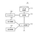
- FIG. 2 is a diagram showing an example of the functional configuration of the route setting device 10.
- the route setting device 10 includes a first acquisition unit 130 and a route setting unit 140.
- the first acquisition unit 130 acquires designated information for designating a plurality of points. When setting these plurality of points, these inspectors make each of the plurality of points overlap with the inspection target.
- the route setting unit 140 sets the line connecting the points moved in the same direction and the same distance from the plurality of points indicated by the designated information as the flight route of the flying object.
- the route setting unit 140 sets a temporary flight route by connecting a plurality of points indicated by the designated information.
- the route setting unit 140 sets the flight route by moving this temporary flight route.
- the route setting unit 140 moves a plurality of points indicated by the designated information in the same direction and in the same distance. Then, the route setting unit 140 sets the flight route of the flying object by connecting a plurality of points after the movement.
- the route setting device 10 further includes a display unit 110, a data storage unit 112, a display 120, and a second acquisition unit 150.
- the data storage unit 112 stores map data or images taken from the sky (for example, aerial photographs and satellite photographs).
- the display unit 110 reads out map data or an image of the inspection target and its surroundings and displays it on the display 120 according to an instruction from the user.
- the position information (for example, latitude / longitude information) of the relevant point is associated with each point.
- the first acquisition unit 130 acquires information for identifying a plurality of selected points on the map or image displayed on the display 120 as the above-mentioned designated information.
- the route setting unit 140 acquires position information for each of the plurality of points designated by the designated information, and sets a temporary flight route using the position information.
- the second acquisition unit 150 acquires information indicating the movement distances of a plurality of points indicated by the designated information (hereinafter referred to as movement instruction information).
- the movement instruction information may include the movement direction of each of the plurality of points. Here, the same travel distance is applied to all of the plurality of points. Then, the route setting unit 140 sets the flight route using the movement instruction information.
- the first acquisition unit 130 and the second acquisition unit 150 acquire necessary information via an input device such as a mouse.
- an input device such as a mouse.
- the display 120 is a touch panel
- at least one of the first acquisition unit 130 and the second acquisition unit 150 may acquire necessary information via the display 120.
- the first acquisition unit 130 acquires information indicating a point selected by the mouse and information indicating a point touch-input to the display 120 as designated information. Further, the second acquisition unit 150 acquires the slide input performed on the display 120 as movement instruction information. In this case, the slide amount indicates the moving distance. In some cases, the slide direction may indicate the moving direction.
- FIG. 3 is a diagram showing an example of the functional configuration of the flying object control device 20.
- the aircraft control device 20 includes a display unit 210, a display 220, an input unit 230, a selection unit 240, and a command generation unit 250.
- the command generation unit 250 acquires the image generated by the image pickup unit 350 of the flying object 30.
- the display unit 210 displays the image acquired by the command generation unit 250 on the display 220. This image contains at least one wire or pipe that can be inspected.
- the input unit 230 displays a line in the image displayed on the display 220 according to the input from the user.
- the selection unit 240 selects an electric wire or a pipe to be inspected by using the line displayed by the input unit 230. For example, when a plurality of electric wires or pipes are included in the image, the selection unit 240 selects an inspection target from the plurality of electric wires or pipes using the line displayed by the input unit 230.
- the command generation unit 250 generates command information for photographing the inspection target while the flying object moves along the inspection target, and transmits the command information to the flying object 30.
- the command generation unit 250 generates command information so that the flight body 30 flies according to the flight route generated by the route setting device 10.
- the command generation unit 250 When the flight route generated by the route setting device 10 is two-dimensional information (for example, latitude / longitude information), the command generation unit 250 describes information indicating the flight height of the flying object 30 (hereinafter referred to as height information). ) Is obtained separately from the flight route. For example, a person who inspects an inspection target (hereinafter referred to as an inspector) inputs height information to the input unit 230.
- the height information may be a fixed value or may change along the flight route.
- the command generation unit 250 includes this height information in the command information.
- the flying object 30 While flying, the flying object 30 repeatedly transmits the position information of the flying object 30 to the flying object control device 20. Then, the command generation unit 250 of the flight body control device 20 repeatedly generates command information so that the flight body 30 moves along the flight route using this position information, and transmits the generated command information to the flight body 30. do.
- the imaging unit 350 of the flying object 30 repeatedly generates an image.
- the command generation unit 250 repeatedly acquires the image generated by the imaging unit 350. Then, each time the command generation unit 250 acquires an image, the command generation unit 250 generates command information based on the position of the inspection target in the image. For example, the command generation unit 250 controls the height of the flying object 30 so that the inspection target comes to the center in the image.
- the command information includes information for controlling the imaging unit 350 (hereinafter referred to as control information).
- This control information is information for controlling at least one of the photographing direction and the magnification of the imaging unit 350.
- the command generation unit 250 generates control information regarding the imaging direction of the imaging unit 350 so that the inspection target comes to the center in the image. Further, the command generation unit 250 generates control information regarding the magnification of the image pickup unit 350 so that the size of the object to be imaged is within the reference range.
- the input unit 230 acquires necessary information via an input device such as a mouse.
- the input unit 230 may acquire necessary information via the display 220.
- the input unit 230 uses a line input (drawn) on the touch panel using a pen, a finger, or the like as information for selecting an inspection target.
- the display unit 210 displays this image on the display 220 every time the command generation unit 250 acquires an image from the flying object 30. At this time, the display unit 210 identifies the position of the inspection target in the image, and then displays at least two markers indicating the inspection target. These two markers are arranged along the inspection target so that the inspection target is located between the two markers.
- the marker is, for example, a solid line, but may be a dotted line or a alternate long and short dash line.
- the display unit 210 acquires information for identifying the inspection target (hereinafter referred to as inspection target identification information).
- the inspection target specific information indicates, for example, the position of the inspection target in the previous image.
- the display unit 210 uses this inspection target identification information to specify the position of the inspection target in the next image and generate the next inspection target identification information.
- the display unit 210 identifies the position of the inspection target in each of the plurality of images generated by the flying object 30.
- the marker is preferably a predetermined color, for example, red.
- red a predetermined color
- FIG. 4 is a diagram showing an example of the functional configuration of the flying object 30.
- the flying object 30 includes a communication unit 310, a flight control unit 320, a drive mechanism 330, an image pickup control unit 340, and an image pickup unit 350.
- the communication unit 310 communicates with the flight object control device 20, receives command information from the flight object control device 20, and transmits the image generated by the image pickup unit 350 to the flight object control device 20.
- the drive mechanism 330 has a motor for driving the propeller of the flying object 30 and a mechanism for controlling the angle of the propeller.
- the flight control unit 320 controls the drive mechanism 330 according to the command information transmitted from the flight body control device 20. At this time, the flight control unit 320 grasps the current position of the flying object 30 by using GPS or the like. Then, the flight control unit 320 controls the movement of the flight body 30 by using the current position of the flight body 30 and the command information. As a result, the flight body 30 can fly according to the flight route set by the route setting device 10 while maintaining the height set by the flight body control device 20.
- the image pickup control unit 340 controls the image pickup unit 350 according to the control information included in the command information. For example, the image pickup control unit 340 controls the image pickup direction of the image pickup unit 350 so that the inspection target comes to the center in the image. Further, the image pickup control unit 340 controls the magnification of the image pickup unit 350 so that the size of the image pickup target is within the reference range. Then, the image pickup control unit 340 transmits the image generated by the image pickup unit 350 to the flying object control device 20 via the communication unit 310.
- FIG. 5 is a diagram showing a hardware configuration example of the route setting device 10.
- the route setting device 10 includes a bus 1010, a processor 1020, a memory 1030, a storage device 1040, an input / output interface 1050, and a network interface 1060.
- the bus 1010 is a data transmission path for the processor 1020, the memory 1030, the storage device 1040, the input / output interface 1050, and the network interface 1060 to transmit and receive data to and from each other.
- the method of connecting the processors 1020 and the like to each other is not limited to the bus connection.
- the processor 1020 is a processor realized by a CPU (Central Processing Unit), a GPU (Graphics Processing Unit), or the like.
- the memory 1030 is a main storage device realized by a RAM (Random Access Memory) or the like.
- the storage device 1040 is an auxiliary storage device realized by an HDD (Hard Disk Drive), an SSD (Solid State Drive), a memory card, a ROM (Read Only Memory), or the like.
- the storage device 1040 stores a program module that realizes each function of the route setting device 10 (for example, a display unit 110, a first acquisition unit 130, a route setting unit 140, and a second acquisition unit 150).
- the processor 1020 reads each of these program modules into the memory 1030 and executes them, each function corresponding to the program module is realized.
- the storage device 1040 also functions as a data storage unit 112.
- the input / output interface 1050 is an interface for connecting the main part of the route setting device 10 and various input / output devices.
- the display 120 communicates with the processor 1020 via the input / output interface 1050.
- the network interface 1060 is an interface for connecting the route setting device 10 to the network.
- This network is, for example, LAN (Local Area Network) or WAN (Wide Area Network).
- the method of connecting the network interface 1060 to the network may be a wireless connection or a wired connection.
- the route setting device 10 may communicate with the aircraft control device 20 via the network interface 1060.
- the hardware configuration of the flying object control device 20 is also the same as the example shown in FIG.
- the storage device 1040 stores a program module that realizes each function of the flight object control device 20 (for example, a display unit 210, an input unit 230, a selection unit 240, and a command generation unit 250).
- the display 220 also communicates with the processor 1020 via the input / output interface 1050.
- the flying object control device 20 may communicate with the route setting device 10 and the flying object 30 via the network interface 1060.
- FIG. 6 is a flowchart showing an example of processing performed by the route setting device 10.
- the route setting device 10 sets the flight route of the flying object 30.
- the display unit 110 of the route setting device 10 reads the map data or image data of the place where the inspection target exists from the data storage unit 112 according to the input from the inspector, and reads the map data or image data on the display 120. Display (step S10).
- the inspector inputs designated information for designating a plurality of points into the first acquisition unit 130 (step S20). For example, when the inspection target is an electric wire, the inspector selects a point where a utility pole or a power transmission tower exists as designated information.
- the route setting unit 140 generates a temporary route by connecting a plurality of points indicated by the designated information.
- the display unit 110 superimposes this temporary route on the map or image displayed in step S10 and displays it on the display 120 (step S30).
- This movement instruction information includes at least the distance to travel on the temporary route.
- the route setting unit 140 generates a flight route by moving the temporary route according to the movement instruction information.
- the moving direction of the temporary route may be, for example, a direction perpendicular to a straight line indicating the temporary route.
- the route setting unit 140 moves each straight line constituting the polygonal line in a direction perpendicular to the straight line. In this way, the flight route can be made parallel to the temporary route.
- the moving distance of each line at this time is the distance indicated by the moving instruction information.
- the display unit 110 superimposes the flight route on the map or image displayed in step S10 and displays it on the display 120 (step S50).
- step S60: Yes The inspector confirms the flight route displayed on the display 120. If this flight route is acceptable (step S60: Yes), the inspector inputs to the second acquisition unit 150 to determine the flight route. Then, the route setting unit 140 transmits the generated flight route to the flight object control device 20. On the other hand, when the flight route is modified (step S60: No), the process returns to step S40.
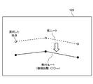
- FIG. 7 shows an example of the screen displayed on the display 120 in step S50.
- the display unit 110 causes the display 120 to display a map or an image taken from the sky.
- the display unit 110 causes the display 120 to superimpose the temporary route on the map or the image.
- the display unit 110 causes the display 120 to display the flight route on the map or the image.
- the display unit 110 causes the display 120 to display the distance from the temporary route to the flight route, that is, the movement distance indicated by the movement instruction information.
- the inspector can confirm the distance between the temporary route and the flight route, that is, the distance from the inspection target to the flying object 30, so that it becomes easy to confirm the validity of the flight route.
- the inspection target is a high-voltage electric wire
- the distance between the temporary route and the flight route is preferably 10 m or more and 15 m or less, for example.
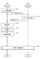
- FIG. 8 shows an example of a process in which the flying object control device 20 controls the flying object 30.
- the image pickup unit 350 of the flying object 30 repeatedly generates an image while the flying object 30 is flying.
- the image pickup control unit 340 of the image pickup unit 350 transmits the image to the flying object control device 20 each time the image pickup unit 350 generates an image.
- the display unit 210 of the flight body control device 20 acquires the flight route from the route setting device 10 (step S110). Then, the command generation unit 250 of the flight body control device 20 generates command information indicating the start point of this flight route and transmits it to the flight body 30 (step S120).
- the flight control unit 320 of the flight body 30 recognizes the start point of the flight route and flies the flight body 30 to this start point (step S130). At this time, the flying object 30 has a designated height. As a result, the imaging unit 350 of the flying object 30 can generate an image at the starting point. This image contains the subject to be inspected. Then, the image pickup control unit 340 of the flying object 30 transmits this image to the flying object control device 20 (step S140).
- the command generation unit 250 of the flight body control device 20 receives the image transmitted from the flight body 30. Then, the display unit 210 displays this image on the display 220 (step S150). This image contains multiple wires and pipes that can be inspected. Therefore, the inspector draws a line along the wiring or piping to be inspected on the image via the input unit 230 of the flying object control device 20 (step S160). Then, the selection unit 240 of the aircraft control device 20 selects the wiring or piping closest to this line as the inspection target (step S170). Specific examples of the inspection target selection method will be described later with reference to other figures.
- step S180 the flight control process of the flying object 30 is performed (step S180). A detailed example of this control process will be described with reference to other figures.
- At least one utility pole or transmission tower may be included in the middle of one flight route. In this case, the processes from step S130 to step S180 are repeated every time the air vehicle 30 passes through the utility pole or the power transmission tower.
- FIG. 9 shows an example of the screen displayed by the display 220 in step S160 of FIG.
- the image taken by the imaging unit 350 of the flying object 30 may include a plurality of electric wires and pipes (electric wires in this figure). In many cases, these electric wires and pipes are provided in parallel with each other. Therefore, if the input method for selecting the inspection target is not devised, the possibility that the flying object control device 20 erroneously recognizes the inspection target increases.
- the inspector inputs a line along the inspection target to the display 220 displaying the image. Then, the selection unit 240 of the flying object control device 20 selects the electric wire or the pipe closest to this line as the inspection target. Therefore, the inspector can easily select a desired electric wire or pipe as an inspection target.
- FIG. 10 shows an example of processing when the selection unit 240 selects an inspection target.
- the selection unit 240 approximates the electric wires and pipes that can be inspected by a straight line by processing the image, and calculates the slope and y-intercept of the straight line in the image. Further, the selection unit 240 performs the same processing on the line input by the inspector, and calculates the slope and y-intercept of this line. Then, the selection unit 240 selects the electric wire or pipe closest to the line input by the inspector as the inspection target in the two-dimensional plane composed of the inclination and the y-intercept.
- FIG. 11 is a flowchart showing a detailed example of step S180 in FIG. The process shown in this figure is repeated while the flying object 30 is flying along the inspection target.
- the display unit 210 of the flight object control device 20 displays the image transmitted from the flight object 30 on the display 220, and at least two markers indicating the inspection target are displayed on the display 220 (step S210). Further, the command generation unit 250 of the flight body control device 20 of the flight body control device 20 generates command information for photographing the inspection target while flying the flight body 30 along the inspection target (step S220), and this command Information is transmitted to the flying object 30 (step S230). As described above, this command information also includes control information for controlling at least one of the photographing direction and the magnification of the imaging unit 350.
- the flight control unit 320 of the flight body 30 flies the flight body 30 according to the command information transmitted from the flight body control device 20 (step S240). Further, the image pickup control unit 340 of the flying object 30 controls at least one of the imaging direction and the magnification of the image pickup unit 350 according to the control information (step S250). Then, the image pickup control unit 340 transmits the image generated by the image pickup unit 350 to the flying object control device 20 (step S260).
- the display unit 210 of the flight object control device 20 identifies the position of the inspection target in the newly acquired image, generates the inspection target identification information using this position (step S270), and returns to step S210.
- the flight control unit 320 of the flying object 30 may perform the processing shown in steps S220 and S270 of FIG.
- the command generation unit 250 of the flight object control device 20 first transmits specific information for identifying the inspection target to the flight object 30.
- An example of this specific information is the coordinates of the inspection target in the two-dimensional plane shown in FIG.
- the flying object 30 repeats the processes shown in steps S220, S240, S250, and S270 in order to follow the specified inspection target.
- the image pickup control unit 340 of the flight object 30 repeatedly transmits the image generated by the image pickup unit 350 to the flight object control device 20 (step S260). Further, the flying object control device 20 performs the processes shown in steps S270 and S210 each time an image is acquired.
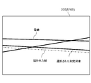
- FIG. 12 shows an example of the screen displayed on the display 220 in step S210 of FIG.
- the display 220 displays an image generated by the imaging unit 350 of the flying object 30, as well as two markers indicating electric wires and pipes recognized by the flying object control device 20 as inspection targets. There is. These two markers are arranged along the inspection target so that the inspection target is located between the two markers. Therefore, the inspector can easily recognize the electric wires and pipes that the flying object control device 20 recognizes as the inspection target.
- the display unit 210 may detect an abnormality (for example, a scratch) occurring in the inspection target by performing image processing. In this case, it is preferable that the display unit 210 displays the detected abnormality on the display 220 so that it can be identified. As an example, the display unit 210 may display a mark at a place where an abnormality exists. This mark is, for example, a frame of a predetermined color (for example, red), but is not limited thereto.
- a plurality of electric wires and pipes to be inspected may be located in parallel.
- the inspector can easily select the electric wire or pipe desired as an inspection target from the plurality of electric wires or pipes.
- two markers indicating electric wires and pipes recognized by the flight object control device 20 as inspection targets are also displayed. These two markers are arranged along the inspection target so that the inspection target is located between the two markers. Therefore, the inspector can easily recognize the electric wires and pipes that the flying object control device 20 recognizes as the inspection target. Then, when the flying object control device 20 recognizes an erroneous electric wire or pipe as an inspection target, the inspector can immediately deal with the erroneous wire or piping.
- a display means for displaying an image captured by an imaging means possessed by an air vehicle, including at least one electric wire or pipe that can be inspected, on a display.
- An input means for drawing a line in the image according to the input from the user,
- a selection means for selecting an inspection target using the line and
- a command generation means for generating command information for photographing the inspection target while the flying object moves along the inspection target and transmitting the command information to the inspection target.
- the command generation means is The image generated by the flying object is repeatedly acquired, and the image is acquired repeatedly.
- An air vehicle control device that generates the command information based on the position of the inspection target in the image when the image is acquired. 3. 3. In the aircraft control device according to 2 above, The imaging means can control at least one of the shooting direction and the magnification. The command information is an air vehicle control device including control information for controlling at least one of the above. 4. In the flying object control device according to 1 above, The command information is an air vehicle control device including specific information for the air vehicle to identify the inspection target. 5. In the aircraft control device according to 4 above, The selection means Each of the at least one electric wire or pipe in the image is approximated by a straight line, and the input line is also approximated by a straight line.
- the command generation means is an air vehicle control device that includes the coordinates of the inspection target in the two-dimensional plane in the command information.
- the inspection target is an electric wire.
- a flying object control method in which a flying object generates command information for photographing the inspection object while moving along the inspection object and transmits the command information to the flying object. 8.
- the computer selects the inspection target, the computer
- the image generated by the flying object is repeatedly acquired, and the image is acquired repeatedly.
- a flying object control method that generates the command information based on the position of the inspection target in the image when the image is acquired.
- the imaging means can control at least one of the shooting direction and the magnification.
- the command information is a flight object control method including control information for controlling at least one of the above. 10.
- the command information is a flight object control method including specific information for the flight object to identify the inspection target.
- the computer Each of the at least one electric wire or pipe in the image is approximated by a straight line, and the input line is also approximated by a straight line. In a two-dimensional plane whose variables are the slope and y-intercept that define a straight line, the wire or pipe closest to the line is selected as the inspection target.
- a flying object control method that includes the coordinates of the inspection target in the two-dimensional plane in the command information. 12.
- the inspection target is an electric wire
- On the computer A display function that displays an image captured by an imaging means of an air vehicle, including at least one electric wire or pipe that can be inspected, on a display.
- An input function that draws a line in the image according to the input from the user, A selection function that selects the inspection target using the line and A command generation function that generates command information for photographing the inspection target while the flying object moves along the inspection target and transmits the command information to the inspection target. Program to have. 14.
- the command generation function is The image generated by the flying object is repeatedly acquired, and the image is acquired repeatedly.
- the imaging means can control at least one of the shooting direction and the magnification.
- the command information is a program including control information for controlling at least one of the above. 16.
- the command information is a program including specific information for the flying object to identify the inspection target. 17.
- the selection function Each of the at least one electric wire or pipe in the image is approximated by a straight line, and the input line is also approximated by a straight line.
- the command generation function is a program that includes the coordinates of the inspection target in the two-dimensional plane in the command information. 18.
- the inspection target is an electric wire
- Route setting device 20
- Aircraft control device 30
- Aircraft 110 Display unit 112
- Data storage unit 120
- First acquisition unit 140
- Route setting unit 150
- Second acquisition unit 210
- Display unit 220 Display 230
- Input unit 240
- Selection unit 250
- Command generation unit 310
- Communication unit 320
- Flight control unit 330
- Drive mechanism 340
- Imaging control unit 350 Imaging unit
Landscapes
- Engineering & Computer Science (AREA)
- Remote Sensing (AREA)
- General Physics & Mathematics (AREA)
- Physics & Mathematics (AREA)
- Aviation & Aerospace Engineering (AREA)
- Radar, Positioning & Navigation (AREA)
- Automation & Control Theory (AREA)
- Theoretical Computer Science (AREA)
- Computer Vision & Pattern Recognition (AREA)
- Mechanical Engineering (AREA)
- Quality & Reliability (AREA)
- Traffic Control Systems (AREA)
- Control Of Position, Course, Altitude, Or Attitude Of Moving Bodies (AREA)
- Navigation (AREA)
- Investigating Materials By The Use Of Optical Means Adapted For Particular Applications (AREA)
Priority Applications (6)
| Application Number | Priority Date | Filing Date | Title |
|---|---|---|---|
| JP2022507071A JP7347651B2 (ja) | 2020-03-11 | 2020-03-11 | 飛行体制御装置、飛行体制御方法、及びプログラム |
| US17/800,729 US12189403B2 (en) | 2020-03-11 | 2020-03-11 | Aircraft control apparatus, aircraft control method, and non-transitory computer-readable medium |
| PCT/JP2020/010479 WO2021181554A1 (ja) | 2020-03-11 | 2020-03-11 | 飛行体制御装置、飛行体制御方法、及びプログラム |
| JP2023144190A JP7574899B2 (ja) | 2020-03-11 | 2023-09-06 | 飛行体制御装置、飛行体制御方法、及びプログラム |
| JP2024181279A JP2025011271A (ja) | 2020-03-11 | 2024-10-16 | プログラム及び飛行体制御方法 |
| US18/959,823 US20250085709A1 (en) | 2020-03-11 | 2024-11-26 | Aircraft control apparatus, aircraft control method, and non-transitory computer-readable medium |
Applications Claiming Priority (1)
| Application Number | Priority Date | Filing Date | Title |
|---|---|---|---|
| PCT/JP2020/010479 WO2021181554A1 (ja) | 2020-03-11 | 2020-03-11 | 飛行体制御装置、飛行体制御方法、及びプログラム |
Related Child Applications (2)
| Application Number | Title | Priority Date | Filing Date |
|---|---|---|---|
| US17/800,729 A-371-Of-International US12189403B2 (en) | 2020-03-11 | 2020-03-11 | Aircraft control apparatus, aircraft control method, and non-transitory computer-readable medium |
| US18/959,823 Continuation US20250085709A1 (en) | 2020-03-11 | 2024-11-26 | Aircraft control apparatus, aircraft control method, and non-transitory computer-readable medium |
Publications (1)
| Publication Number | Publication Date |
|---|---|
| WO2021181554A1 true WO2021181554A1 (ja) | 2021-09-16 |
Family
ID=77671325
Family Applications (1)
| Application Number | Title | Priority Date | Filing Date |
|---|---|---|---|
| PCT/JP2020/010479 Ceased WO2021181554A1 (ja) | 2020-03-11 | 2020-03-11 | 飛行体制御装置、飛行体制御方法、及びプログラム |
Country Status (3)
| Country | Link |
|---|---|
| US (2) | US12189403B2 (https=) |
| JP (3) | JP7347651B2 (https=) |
| WO (1) | WO2021181554A1 (https=) |
Cited By (1)
| Publication number | Priority date | Publication date | Assignee | Title |
|---|---|---|---|---|
| JP7490103B1 (ja) | 2023-02-27 | 2024-05-24 | Tepco光ネットワークエンジニアリング株式会社 | 飛行ルート設定方法、飛行制御方法、保守点検方法、飛行ルート設定システムおよびプログラム |
Families Citing this family (1)
| Publication number | Priority date | Publication date | Assignee | Title |
|---|---|---|---|---|
| US12326729B2 (en) * | 2020-10-23 | 2025-06-10 | Deere &Company | Methods, apparatus, and articles of manufacture to display acquisition paths |
Citations (4)
| Publication number | Priority date | Publication date | Assignee | Title |
|---|---|---|---|---|
| JP2005265699A (ja) * | 2004-03-19 | 2005-09-29 | Chugoku Electric Power Co Inc:The | 無人飛行体を用いた送電線点検システムおよび方法 |
| WO2015163106A1 (ja) * | 2014-04-25 | 2015-10-29 | ソニー株式会社 | 制御装置、撮像装置、制御方法、撮像方法及びコンピュータプログラム |
| JP2018156491A (ja) * | 2017-03-17 | 2018-10-04 | 東京電力ホールディングス株式会社 | 設備点検システム |
| JP2018169995A (ja) * | 2017-03-30 | 2018-11-01 | 株式会社スカイマティクス | ドローンを用いた作業を支援するシステムおよび方法 |
Family Cites Families (6)
| Publication number | Priority date | Publication date | Assignee | Title |
|---|---|---|---|---|
| JP2014212479A (ja) * | 2013-04-19 | 2014-11-13 | ソニー株式会社 | 制御装置、制御方法及びコンピュータプログラム |
| US20170010816A1 (en) | 2014-04-18 | 2017-01-12 | Hewlett Packard Enterprise Developmentt Lp | Providing combined data from a cache and a storage device |
| KR101769718B1 (ko) | 2016-09-21 | 2017-08-18 | 한국전력공사 | 송전선로 전자계 및 순시 점검 영상 취득 장치 및 방법 |
| JP2018160228A (ja) | 2017-03-21 | 2018-10-11 | 株式会社東芝 | 経路生成装置、経路制御システム、及び経路生成方法 |
| JP2019196980A (ja) | 2018-05-09 | 2019-11-14 | 株式会社センシンロボティクス | 検査システム |
| KR102344195B1 (ko) * | 2020-01-10 | 2021-12-28 | 한국전력공사 | 전력선 촬영 방법 |
-
2020
- 2020-03-11 JP JP2022507071A patent/JP7347651B2/ja active Active
- 2020-03-11 WO PCT/JP2020/010479 patent/WO2021181554A1/ja not_active Ceased
- 2020-03-11 US US17/800,729 patent/US12189403B2/en active Active
-
2023
- 2023-09-06 JP JP2023144190A patent/JP7574899B2/ja active Active
-
2024
- 2024-10-16 JP JP2024181279A patent/JP2025011271A/ja active Pending
- 2024-11-26 US US18/959,823 patent/US20250085709A1/en active Pending
Patent Citations (4)
| Publication number | Priority date | Publication date | Assignee | Title |
|---|---|---|---|---|
| JP2005265699A (ja) * | 2004-03-19 | 2005-09-29 | Chugoku Electric Power Co Inc:The | 無人飛行体を用いた送電線点検システムおよび方法 |
| WO2015163106A1 (ja) * | 2014-04-25 | 2015-10-29 | ソニー株式会社 | 制御装置、撮像装置、制御方法、撮像方法及びコンピュータプログラム |
| JP2018156491A (ja) * | 2017-03-17 | 2018-10-04 | 東京電力ホールディングス株式会社 | 設備点検システム |
| JP2018169995A (ja) * | 2017-03-30 | 2018-11-01 | 株式会社スカイマティクス | ドローンを用いた作業を支援するシステムおよび方法 |
Cited By (2)
| Publication number | Priority date | Publication date | Assignee | Title |
|---|---|---|---|---|
| JP7490103B1 (ja) | 2023-02-27 | 2024-05-24 | Tepco光ネットワークエンジニアリング株式会社 | 飛行ルート設定方法、飛行制御方法、保守点検方法、飛行ルート設定システムおよびプログラム |
| JP2024121260A (ja) * | 2023-02-27 | 2024-09-06 | Tepco光ネットワークエンジニアリング株式会社 | 飛行ルート設定方法、飛行制御方法、保守点検方法、飛行ルート設定システムおよびプログラム |
Also Published As
| Publication number | Publication date |
|---|---|
| JP7347651B2 (ja) | 2023-09-20 |
| JP7574899B2 (ja) | 2024-10-29 |
| US20230094918A1 (en) | 2023-03-30 |
| JPWO2021181554A1 (https=) | 2021-09-16 |
| JP2025011271A (ja) | 2025-01-23 |
| US20250085709A1 (en) | 2025-03-13 |
| US12189403B2 (en) | 2025-01-07 |
| JP2023171742A (ja) | 2023-12-05 |
Similar Documents
| Publication | Publication Date | Title |
|---|---|---|
| JP2025011271A (ja) | プログラム及び飛行体制御方法 | |
| JP6583840B1 (ja) | 検査システム | |
| EP3961578B1 (en) | Perception-based autonomous landing for aircraft | |
| CN114721419B (zh) | 基于无人机的输电线路的杆塔巡检方法、装置、以及设备 | |
| CN110244765B (zh) | 一种飞行器航线轨迹生成方法、装置、无人机及存储介质 | |
| JP7511735B2 (ja) | コンピュータプログラム | |
| JP7004374B1 (ja) | 移動体の移動経路生成方法及びプログラム、管理サーバ、管理システム | |
| JP2018077626A (ja) | 飛行制御装置、飛行制御方法、及びプログラム | |
| CN111581322B (zh) | 视频中兴趣区域在地图窗口内显示的方法和装置及设备 | |
| JP6929211B2 (ja) | 航空機の飛行経路の安全性を判断するための方法、プログラムおよび装置 | |
| JP2019211486A (ja) | 検査システム | |
| KR20230082497A (ko) | 3차원 포인트 클라우드를 이용한 구조물의 실시간 검진 자동화 방법 및 장치 | |
| JP2022037971A (ja) | 無人飛行体の飛行経路作成方法及びシステム | |
| CN115825067A (zh) | 一种基于无人机的地质信息采集方法、系统及电子设备 | |
| WO2021181553A1 (ja) | ルート設定装置、ルート設定方法、及びプログラム | |
| WO2021181578A1 (ja) | 表示制御装置、表示制御方法、及びプログラム | |
| JP6807092B1 (ja) | 点検システム及び管理サーバ、プログラム、ヒビ割れ情報提供方法 | |
| JP2006270404A (ja) | 撮影制御装置、撮影制御方法および撮影制御プログラム | |
| JP2020016664A (ja) | 検査システム | |
| KR101440503B1 (ko) | 위성영상 기반의 교관석 화면을 제공하는 비행시뮬레이터 장치 | |
| CN116805397A (zh) | 用于使用机器学习算法检测和识别图像中的小对象的系统和方法 | |
| JP7605417B1 (ja) | 情報処理方法、情報処理システム及びプログラム | |
| JP7020418B2 (ja) | 情報処理装置、情報処理方法、およびプログラム | |
| US12400385B2 (en) | Information processing apparatus, information processing method, program, and information processing system | |
| US20240412405A1 (en) | Uav, control terminal, server, and control method |
Legal Events
| Date | Code | Title | Description |
|---|---|---|---|
| 121 | Ep: the epo has been informed by wipo that ep was designated in this application |
Ref document number: 20923751 Country of ref document: EP Kind code of ref document: A1 |
|
| ENP | Entry into the national phase |
Ref document number: 2022507071 Country of ref document: JP Kind code of ref document: A |
|
| NENP | Non-entry into the national phase |
Ref country code: DE |
|
| 122 | Ep: pct application non-entry in european phase |
Ref document number: 20923751 Country of ref document: EP Kind code of ref document: A1 |