WO2021172402A1 - 中空樹脂粒子の製造方法 - Google Patents
中空樹脂粒子の製造方法 Download PDFInfo
- Publication number
- WO2021172402A1 WO2021172402A1 PCT/JP2021/007008 JP2021007008W WO2021172402A1 WO 2021172402 A1 WO2021172402 A1 WO 2021172402A1 JP 2021007008 W JP2021007008 W JP 2021007008W WO 2021172402 A1 WO2021172402 A1 WO 2021172402A1
- Authority
- WO
- WIPO (PCT)
- Prior art keywords
- particles
- hollow resin
- resin particles
- hydrocarbon
- precursor
- Prior art date
- Legal status (The legal status is an assumption and is not a legal conclusion. Google has not performed a legal analysis and makes no representation as to the accuracy of the status listed.)
- Ceased
Links
Images


Classifications
-
- C—CHEMISTRY; METALLURGY
- C08—ORGANIC MACROMOLECULAR COMPOUNDS; THEIR PREPARATION OR CHEMICAL WORKING-UP; COMPOSITIONS BASED THEREON
- C08F—MACROMOLECULAR COMPOUNDS OBTAINED BY REACTIONS ONLY INVOLVING CARBON-TO-CARBON UNSATURATED BONDS
- C08F265/00—Macromolecular compounds obtained by polymerising monomers on to polymers of unsaturated monocarboxylic acids or derivatives thereof as defined in group C08F20/00
- C08F265/04—Macromolecular compounds obtained by polymerising monomers on to polymers of unsaturated monocarboxylic acids or derivatives thereof as defined in group C08F20/00 on to polymers of esters
- C08F265/06—Polymerisation of acrylate or methacrylate esters on to polymers thereof
-
- C—CHEMISTRY; METALLURGY
- C08—ORGANIC MACROMOLECULAR COMPOUNDS; THEIR PREPARATION OR CHEMICAL WORKING-UP; COMPOSITIONS BASED THEREON
- C08F—MACROMOLECULAR COMPOUNDS OBTAINED BY REACTIONS ONLY INVOLVING CARBON-TO-CARBON UNSATURATED BONDS
- C08F2/00—Processes of polymerisation
- C08F2/12—Polymerisation in non-solvents
- C08F2/16—Aqueous medium
- C08F2/18—Suspension polymerisation
-
- C—CHEMISTRY; METALLURGY
- C08—ORGANIC MACROMOLECULAR COMPOUNDS; THEIR PREPARATION OR CHEMICAL WORKING-UP; COMPOSITIONS BASED THEREON
- C08F—MACROMOLECULAR COMPOUNDS OBTAINED BY REACTIONS ONLY INVOLVING CARBON-TO-CARBON UNSATURATED BONDS
- C08F220/00—Copolymers of compounds having one or more unsaturated aliphatic radicals, each having only one carbon-to-carbon double bond, and only one being terminated by only one carboxyl radical or a salt, anhydride ester, amide, imide or nitrile thereof
- C08F220/02—Monocarboxylic acids having less than ten carbon atoms; Derivatives thereof
- C08F220/10—Esters
- C08F220/12—Esters of monohydric alcohols or phenols
- C08F220/14—Methyl esters, e.g. methyl (meth)acrylate
-
- C—CHEMISTRY; METALLURGY
- C08—ORGANIC MACROMOLECULAR COMPOUNDS; THEIR PREPARATION OR CHEMICAL WORKING-UP; COMPOSITIONS BASED THEREON
- C08F—MACROMOLECULAR COMPOUNDS OBTAINED BY REACTIONS ONLY INVOLVING CARBON-TO-CARBON UNSATURATED BONDS
- C08F6/00—Post-polymerisation treatments
- C08F6/24—Treatment of polymer suspensions
-
- C—CHEMISTRY; METALLURGY
- C08—ORGANIC MACROMOLECULAR COMPOUNDS; THEIR PREPARATION OR CHEMICAL WORKING-UP; COMPOSITIONS BASED THEREON
- C08J—WORKING-UP; GENERAL PROCESSES OF COMPOUNDING; AFTER-TREATMENT NOT COVERED BY SUBCLASSES C08B, C08C, C08F, C08G or C08H
- C08J9/00—Working-up of macromolecular substances to porous or cellular articles or materials; After-treatment thereof
- C08J9/0014—Use of organic additives
- C08J9/0028—Use of organic additives containing nitrogen
-
- B—PERFORMING OPERATIONS; TRANSPORTING
- B01—PHYSICAL OR CHEMICAL PROCESSES OR APPARATUS IN GENERAL
- B01J—CHEMICAL OR PHYSICAL PROCESSES, e.g. CATALYSIS OR COLLOID CHEMISTRY; THEIR RELEVANT APPARATUS
- B01J13/00—Colloid chemistry, e.g. the production of colloidal materials or their solutions, not otherwise provided for; Making microcapsules or microballoons
- B01J13/02—Making microcapsules or microballoons
-
- C—CHEMISTRY; METALLURGY
- C08—ORGANIC MACROMOLECULAR COMPOUNDS; THEIR PREPARATION OR CHEMICAL WORKING-UP; COMPOSITIONS BASED THEREON
- C08J—WORKING-UP; GENERAL PROCESSES OF COMPOUNDING; AFTER-TREATMENT NOT COVERED BY SUBCLASSES C08B, C08C, C08F, C08G or C08H
- C08J2351/00—Characterised by the use of graft polymers in which the grafted component is obtained by reactions only involving carbon-to-carbon unsaturated bonds; Derivatives of such polymers
Definitions
- This disclosure relates to a method for producing hollow resin particles. More specifically, the present disclosure relates to a production method capable of obtaining hollow resin particles in which the residual amount of the non-reactive hydrocarbon solvent once held inside the particles in the production process is reduced.
- Hollow resin particles produced by polymerizing a polymerizable monomer are particles having cavities inside the particles, and scatter light better than solid particles whose inside is substantially filled with resin. It is possible to reduce the light transmission. Therefore, the hollow resin particles are widely used as organic pigments having excellent optical properties such as opacity and whiteness and as concealing agents for water-based paints, paper coating compositions, etc., and further, light reflectors and heat insulating plates. It is also used as an additive for molded bodies such as materials and sound insulation materials.
- Patent Document 1 describes that a hollow polymer particle having a single-layer structure and a large void ratio can be crosslinked in an aqueous solution of a dispersion stabilizer for the purpose of producing hollow polymer particles in a short process and by a simple method.
- a method of dispersing a monomer or a mixture of a crosslinkable monomer and a monofunctional monomer, an initiator, and a poorly water-soluble solvent to carry out suspension polymerization is disclosed.
- Patent Document 1 describes, as a method for removing a solvent existing in a hollow portion, a method of drying hollow polymer particles in the form of suspension or powder under conditions of a temperature of 20 to 300 ° C. and a pressure of about 1 to 100,000 Pa.
- the hollow polymer fine particles are isolated and dried under the conditions of a temperature of about 70 ° C. and a pressure of about 100,000 Pa (under atmospheric pressure) to evaporate hexadecane (boiling point 287 ° C.) in the core portion. ing.
- Patent Document 2 describes a mixture containing a polyfunctional monomer and a non-reactive solvent for the purpose of producing hollow resin particles having a high void ratio and having sustained release properties by providing pores formed in the shell. A method of dispersing the solution in an aqueous solution and then polymerizing the polyfunctional monomer is disclosed. Patent Document 2 only discloses a method of heating the hollow resin particles at the boiling point T ⁇ 10 ° C. of the non-reactive organic solvent as a method of removing the non-reactive organic solvent in the hollow resin particles.
- Patent Document 3 as a method for producing hollow resin particles by heating and expanding thermally expandable microcapsules, a volatile liquid and / or a sublimable solid is encapsulated as an expander in a polymer shell made of a thermoplastic polymer.
- a method of continuously supplying and discharging the heat-expandable microcapsules to an indirect heating type stirring / drying machine having a heat transfer area / effective volume of 10 m- 1 or more is disclosed.
- JP-A-2002-80503 Japanese Unexamined Patent Publication No. 2016-190980 Japanese Unexamined Patent Publication No. 2007-191694
- Patent Document 1 In the production method for obtaining hollow resin particles by polymerizing a polymerizable monomer in an aqueous medium by a suspension polymerization method, as a method for removing the poorly water-soluble organic solvent contained in the hollow resin particles, Patent Document 1 and As disclosed in No. 2, conventionally, a method of drying hollow resin particles at a temperature equal to or lower than the boiling point of the organic solvent has been adopted.
- the proportion of the crosslinkable monomer is increased in order to increase the strength of the shell as the polymerizable monomer forming the shell of the hollow resin particles, the hollow resin particles are dried by a conventional method.
- the present disclosure has been made in view of the above circumstances, and the subject of the present disclosure is a hollow resin in which the residual amount of the hydrocarbon solvent once held inside the particles in the manufacturing process is reduced and the damage is suppressed. It is to provide the manufacturing method of the hollow resin particle which can obtain the particle.
- the first method for producing hollow resin particles of the present disclosure is A step of preparing a mixed solution containing a polymerizable monomer, a hydrocarbon solvent, a polymerization initiator, and an aqueous medium.
- a mixed solution containing a polymerizable monomer, a hydrocarbon solvent, a polymerization initiator, and an aqueous medium.
- droplets of the polymerizable monomer composition containing the polymerizable monomer, the hydrocarbon-based solvent, and the polymerization initiator were dispersed in the aqueous medium.
- the process of preparing the suspension and A step of preparing a precursor composition containing precursor particles having a hollow portion and containing the hydrocarbon solvent in the hollow portion by subjecting the suspension to a polymerization reaction.
- the polymerizable monomer contains a crosslinkable monomer in a proportion of 40 to 100% by mass.
- the boiling point T 1 of the hydrocarbon solvent is 70 to 90 ° C.
- the porosity of the hollow resin particles is preferably 50 to 95%.
- the pressure at the time of heating and drying in the step of removing the hydrocarbon solvent is preferably 0 to 101.3 kPa.
- the hydrocarbon solvent is a hydrocarbon solvent having 4 to 7 carbon atoms.
- the water content of the precursor particles used in the step of removing the hydrocarbon solvent is preferably 50% or less.
- At least one kind of precursor particles separated from the aqueous medium is selected from the group consisting of inorganic fine particles and organic fine particles. It is a step of covering the surface of the precursor particles with the fine particles and removing the hydrocarbon-based solvent contained in the precursor particles by heating and drying together with the fine particles while stirring in a stirring container. Is preferable.
- the second method for producing hollow resin particles of the present disclosure is as follows.
- a step of preparing a mixed solution containing a polymerizable monomer, a hydrocarbon solvent, a polymerization initiator, and an aqueous medium By suspending the mixed solution, droplets of the polymerizable monomer composition containing the polymerizable monomer, the hydrocarbon-based solvent, and the polymerization initiator were dispersed in the aqueous medium.
- the polymerizable monomer contains a crosslinkable monomer in a proportion of 40 to 100% by mass.
- the step of removing the hydrocarbon solvent is carried out by heating and drying the precursor particles while stirring them in a vertical stirring type stirring container provided with a shaft extending in the direction of gravity and a stirring blade. It is a step of removing the hydrocarbon solvent contained in the particles.
- the porosity of the hollow resin particles is preferably 50 to 95%.
- the hydrocarbon solvent is removed with respect to the boiling point T 1 (° C.) of the hydrocarbon solvent and the thermal decomposition start temperature T 2 (° C.) of the precursor particles.
- temperature T 0 of the heat-drying at (°C) preferably satisfies the T 1 ⁇ T 0 ⁇ T 2 -5.
- the stirring container used in the step of removing the hydrocarbon solvent is cylindrical or conical.
- the aqueous system is formed by solid-liquid separation of the precursor composition after the step of preparing the precursor composition and before the step of removing the hydrocarbon solvent. It is preferable to further have a step of obtaining the precursor particles separated from the medium.
- the step of removing the hydrocarbon-based solvent is such that the precursor particles are contained in the stirring container together with at least one fine particle selected from the group consisting of inorganic fine particles and organic fine particles. It is preferable that the surface of the precursor particles is covered with the fine particles and the hydrocarbon-based solvent contained in the precursor particles is removed by heating and drying with stirring.
- the third method for producing hollow resin particles of the present disclosure is A step of preparing a mixed solution containing a polymerizable monomer, a hydrocarbon solvent, a polymerization initiator, and an aqueous medium.
- a mixed solution containing a polymerizable monomer, a hydrocarbon solvent, a polymerization initiator, and an aqueous medium.
- droplets of the polymerizable monomer composition containing the polymerizable monomer, the hydrocarbon-based solvent, and the polymerization initiator were dispersed in the aqueous medium.
- the process of preparing the suspension and A step of preparing a precursor composition containing precursor particles having a hollow portion and containing the hydrocarbon solvent in the hollow portion by subjecting the suspension to a polymerization reaction. It comprises a step of removing the hydrocarbon solvent contained in the precursor particles.
- the polymerizable monomer contains a crosslinkable monomer in a proportion of 40 to 100% by mass.
- the step of removing the hydrocarbon solvent is carried out by heating and drying the precursor particles while stirring them in a horizontal stirring type stirring container provided with a shaft extending in the horizontally direction and a stirring blade. It is a step of removing the hydrocarbon solvent contained in the above.
- the porosity of the hollow resin particles is preferably 50 to 95%.
- the hydrocarbon solvent is removed with respect to the boiling point T 1 (° C.) of the hydrocarbon solvent and the thermal decomposition start temperature T 2 (° C.) of the precursor particles.
- temperature T 0 of the heat-drying at (°C) preferably satisfies the T 1 ⁇ T 0 ⁇ T 2 -5.
- the step of removing the hydrocarbon solvent is continuous drying provided with a plurality of horizontally extending shafts and a multi-axis horizontal stirring container provided with stirring blades. It is preferably carried out using a machine.
- the aqueous system is formed by solid-liquid separation of the precursor composition after the step of preparing the precursor composition and before the step of removing the hydrocarbon solvent. It is preferable to further have a step of obtaining the precursor particles separated from the medium.
- the step of removing the hydrocarbon-based solvent is such that the precursor particles are contained in the stirring container together with at least one fine particle selected from the group consisting of inorganic fine particles and organic fine particles. It is preferable that the surface of the precursor particles is covered with the fine particles and the hydrocarbon-based solvent contained in the precursor particles is removed by heating and drying with stirring.
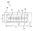
- FIG. 5 is a cross-sectional view taken along the line AA of the horizontal stirring dryer shown in FIG.
- particles having a shell and a hollow portion surrounded by the shell and the hollow portion filled with a hydrocarbon solvent are intermediate between the hollow resin particles obtained by the production method of the present disclosure.
- a precursor particle it is called a precursor particle.
- the composition containing the precursor particles is referred to as a precursor composition.
- “-" in the numerical range means that the numerical values described before and after the numerical range are independently included as the lower limit value and the upper limit value, respectively.
- productivity means the effectiveness of the dryer used in the solvent removing step by dividing the weight (kg) of the obtained hollow resin particles by the heating and drying time (h) in the solvent removing step.
- the vertical stirring method is a stirring method performed by a stirring container provided with a shaft extending in the direction of gravity and a stirring blade
- the horizontal stirring method is a stirring method provided with a shaft extending in the horizontal direction and a stirring blade. It is a stirring method performed by a container.
- the shaft extending in the gravity direction and the shaft extending in the horizontal direction may be slightly inclined within, for example, ⁇ 5 ° with respect to the gravity direction and the horizontal direction, respectively.
- a dryer that dries in a vertical agitation type stirring container may be referred to as a vertical agitation dryer
- a dryer that dries in a horizontal agitation type agitation container is referred to as a horizontal agitation dryer.
- the method for producing hollow resin particles in the first disclosure is a mixture containing a polymerizable monomer, a hydrocarbon-based solvent, a polymerization initiator, and an aqueous medium.
- the polymerizable monomer contains a crosslinkable monomer in a proportion of 40 to 100% by mass.
- the polymerizable monomer and the hydrocarbon solvent are phased by suspending the mixed solution containing the polymerizable monomer, the hydrocarbon solvent, the polymerization initiator and the aqueous medium. Separated to prepare a suspension in which the polymerizable monomer is unevenly distributed on the surface side and the hydrocarbon-based solvent is dispersed in the aqueous medium having a distributed structure in which the hydrocarbon-based solvent is unevenly distributed in the central portion.
- the surface of the droplet is cured by subjecting such a suspension to a polymerization reaction, and a shell composed of a resin and a hollow portion filled with a hydrocarbon solvent are used.
- the hollow resin particles obtained by such a basic technique are particles including a shell (outer shell) containing a resin and a hollow portion surrounded by the shell.
- the hollow portion is a hollow space that is clearly distinguished from the shell formed of the resin material.
- the shell of the hollow resin particles may have a porous structure, in which case the hollow portion has a size that is clearly distinguishable from a large number of minute spaces uniformly dispersed in the porous structure. have.
- the hollow portion is once filled with a hydrocarbon solvent in the manufacturing process.
- the hollow resin particles when the hollow resin particles are kneaded with other materials such as resin and used, if the hollow resin particles contain a hydrocarbon solvent, the hydrocarbon solvent in the hollow resin particles volatilizes. It may foam or cause ignition. Further, the hollow resin particles having a high content of the hydrocarbon solvent have a heavier specific gravity than the hollow resin particles having a low content of the hydrocarbon solvent, so that the effect of the hollow resin particles as a weight-reducing material is inferior. There is also. Therefore, there is a demand for hollow resin particles from which the hydrocarbon solvent has been sufficiently removed.
- the precursor particles in a state containing a hydrocarbon-based solvent are first separated from the aqueous medium, and then the boiling point of the hydrocarbon-based solvent is T 1 (° C.) + 70 ° C. or higher. and dried by heating in the precursor thermal decomposition temperature T 2 -5 ° C. below the temperature of the particles, while suppressing breakage of the particles, a hydrocarbon solvent which has been enclosed can be sufficiently removed.
- the effect of reducing the residual amount of the hydrocarbon solvent in the hollow resin particles by the first production method of the present disclosure is particularly effective when producing hollow resin particles having a shell having no communication holes and shell defects. It is demonstrated in.
- the shell does not have a communication hole through which the hollow portion and the external space of the particle pass, and the hollow portion is isolated from the outside of the particle by the shell, and the shell has one or more communication holes.
- the hollow portion communicates with the outside of the particle through the communication hole.
- the size of the communication holes of the hollow resin particles is appropriately adjusted according to the size of the hollow resin particles, but is usually 10 to 500 nm in diameter.
- the shell defect of the hollow resin particle means a crack-like defect which is extremely large for the size of the particle. Although it depends on the size of the hollow resin particles, a crack having a length of 1 ⁇ m or more is generally recognized as a shell defect because the strength of the hollow resin particles is significantly deteriorated.
- the shell of the hollow resin particles has a communication hole or a shell defect, the hollow resin particle is easily crushed when kneaded with another material such as a resin, or the other material is hollow from the communication hole or the shell defect. There is a problem that it easily enters the inside of the resin particles. Therefore, there is a demand for hollow resin particles having a communication hole and a shell having no shell defect.
- the fact that the shell does not have the communication hole and the shell defect means that the shell does not have the communication hole and the shell defect substantially, and 100 hollow resin particles are observed by SEM and the communication hole or the shell defect is observed. If the number of hollow resin particles having the above is 5 or less, it is assumed that there are no communication holes and shell defects.
- Hollow resin particles having a shell having no communication holes and shell defects are, for example, bifunctional crosslinked as a crosslinkable monomer in the polymerizable monomer forming the shell in the first production method of the present disclosure. It can be produced by using a sex monomer.
- the polymerization rate of the polymerizable monomer in the polymerization step does not become too high and the shell is less likely to be distorted. It is presumed that defects are unlikely to be formed.
- the first manufacturing method of the present disclosure includes the following steps (1) to (5), and is not particularly limited, but may further include steps other than these.
- steps (1) to (5) are not particularly limited, but may further include steps other than these.
- two or more steps of each step may be performed simultaneously as one step, or the order may be changed. ..
- the preparation of the mixed solution and the preparation of the suspension may be performed simultaneously in one step, for example, the material for preparing the mixed solution is charged and suspended at the same time.
- (1) Mixing solution preparation step A step of preparing a mixed solution containing a polymerizable monomer, a hydrocarbon solvent, a polymerization initiator, and an aqueous medium
- Suspension step Suspension of the mixed solution.
- a step of preparing a suspension in which droplets of a polymerizable monomer composition containing a polymerizable monomer, a hydrocarbon solvent, and a polymerization initiator are dispersed in an aqueous medium (3) Polymerization step.
- a step of preparing a precursor composition containing precursor particles having a hollow portion and containing a hydrocarbon solvent in the hollow portion by subjecting the suspension to a polymerization reaction (4) Solid-liquid separation step.
- FIG. 1 is a schematic view showing an example of the first manufacturing method of the present disclosure.
- (1) to (5) in FIG. 1 correspond to the respective steps (1) to (5).
- the white arrows between the figures indicate the order of each step.
- FIG. 1 is merely a schematic diagram for explanation, and the first manufacturing method of the present disclosure is not limited to that shown in the figure. Further, the structure, dimensions and shape of the materials used in each of the manufacturing methods of the present disclosure are not limited to the structures, dimensions and shapes of various materials in these figures.
- FIG. 1 (1) is a schematic cross-sectional view showing an embodiment of the mixed liquid in the mixed liquid preparation step. As shown in this figure, the mixed solution contains an aqueous medium 1 and a low-polarity material 2 dispersed in the aqueous medium 1.
- the low-polarity material 2 means a material having low polarity and which is difficult to mix with the aqueous medium 1.
- the low-polarity material 2 contains a polymerizable monomer, a hydrocarbon solvent, and a polymerization initiator.
- FIG. 1 (2) is a schematic cross-sectional view showing an embodiment of the suspension in the suspension preparation step.
- the suspension contains an aqueous medium 1 and droplets 10 of a polymerizable monomer composition dispersed in the aqueous medium 1.
- the droplet 10 of the polymerizable monomer composition contains a polymerizable monomer, a hydrocarbon solvent and a polymerization initiator, but the distribution of each material in the droplet is not uniform.
- FIG. 1 (3) is a schematic cross-sectional view showing an embodiment of the precursor composition after the polymerization step.
- the precursor composition contains an aqueous medium 1 and precursor particles 20 dispersed in the aqueous medium 1.
- FIG. 1 (4) is a schematic cross-sectional view showing an embodiment of the precursor particles after the solid-liquid separation step.
- the precursor particles after the solid-liquid separation step are the precursor particles 20 separated from the aqueous medium 1 in the precursor composition shown in FIG. 1 (3).
- FIG. 1 (5) is a schematic cross-sectional view showing an embodiment of the hollow resin particles after the solvent removing step.
- the hollow resin particles 100 after the solvent removing step are particles obtained by removing the hydrocarbon solvent 4a contained in the precursor particles from the precursor particles 20 after the solid-liquid separation step shown in FIG. 1 (4). , Has a hollow portion 7 inside the shell 6.
- This step is a step of preparing a mixed liquid containing a polymerizable monomer, a hydrocarbon solvent, a polymerization initiator, and an aqueous medium.
- the mixed solution may further contain other materials such as a suspension stabilizer.
- the polymerizable monomer is a compound having a polymerizable functional group, and a compound having an ethylenically unsaturated bond is generally used as the polymerizable functional group.
- the polymerizable monomer contains at least a crosslinkable monomer and may further contain a non-crosslinkable monomer.
- the non-crosslinkable monomer is a polymerizable monomer having only one polymerizable functional group, and the crosslinkable monomer has two or more polymerizable functional groups, and the resin is subjected to a polymerization reaction. It is a polymerizable monomer that forms a cross-linking bond inside.
- the crosslinkable monomer has a plurality of polymerizable functional groups, by including the crosslinkable monomer as the polymerizable monomer, the monomers can be linked to each other in the polymerization step, and the crosslinkability of the shell can be increased. Can be enhanced.
- crosslinkable monomer examples include bifunctional crosslinkability such as divinylbenzene, divinyldiphenyl, divinylnaphthalene, diallyl phthalate, allyl (meth) acrylate, ethylene glycol di (meth) acrylate, and pentaerythritol di (meth) acrylate.
- Trifunctional such as trimethylolpropane tri (meth) acrylate, ditrimethylolpropane tetra (meth) acrylate, pentaerythritol tri (meth) acrylate, pentaerythritol tetra (meth) acrylate and dipentaerythritol hexa (meth) acrylate.
- the above crosslinkable monomers and the like can be mentioned.
- bifunctional crosslinkable monomers are preferable, and divinylbenzene, ethylene glycol di (meth) acrylate and pentaerythritol di (meth) acrylate are more preferable, because communication holes and shell defects are less likely to be formed in the shell.
- Ethylene glycol di (meth) acrylate and pentaerythritol di (meth) acrylate are more preferred.
- These crosslinkable monomers can be used alone or in combination of two or more.
- (meth) acrylate means each of acrylate or methacrylate
- (meth) acrylic means each of acrylic or methacryl.
- a monovinyl monomer is preferably used as the non-crosslinkable monomer.
- the monovinyl monomer is a compound having one polymerizable vinyl functional group.
- Examples of the monovinyl monomer include methyl (meth) acrylate, ethyl (meth) acrylate, butyl (meth) acrylate, 2-ethylhexyl (meth) acrylate, lauryl (meth) acrylate, glycidyl (meth) acrylate, and 2-hydroxy.
- (Meta) acrylic monovinyl monomers such as ethyl (meth) acrylate and (meth) acrylic acid; aromatic vinyl monomers such as styrene, vinyl toluene, ⁇ -methylstyrene, p-methylstyrene, and halogenated styrene; Monoolefin monomers such as ethylene, propylene and butylene; (meth) acrylamide monomers such as (meth) acrylamide, N-methylol (meth) acrylamide and N-butoxymethyl (meth) acrylamide and derivatives thereof; butadiene, isoprene Diene-based monomers such as; carboxylic acid vinyl ester monomers such as vinyl acetate; vinyl halide monomers such as vinyl chloride; vinylidene halide monomers such as vinylidene chloride; vinyl pyridine monomers; etc.
- aromatic vinyl monomers such as styrene, vinyl toluene, ⁇ -
- (meth) acrylic monovinyl monomer is preferable, and (meth) acrylic acid and butyl butyl are preferable from the viewpoint that the polymerization reaction is easy to stabilize and hollow resin particles having high heat resistance can be obtained. More preferably, at least one selected from acrylates and methyl methacrylates. These non-crosslinkable monomers can be used alone or in combination of two or more.
- the polymerizable monomer used in the present disclosure is the crosslinkable monomer based on 100% by mass of the total amount of the polymerizable monomer in which the crosslinkable monomer and the non-crosslinkable monomer are combined. It is contained in a proportion of 40 to 100% by mass.
- the content ratio of the crosslinkable monomer is not more than the lower limit value, the content ratio of the crosslinkable monomer unit in the shell of the hollow resin particles is sufficiently large, so that the covalent bond network is dense in the shell.
- the obtained hollow resin particles have excellent strength, are not easily crushed, and are not easily deformed by heat applied from the outside.
- the content ratio of the crosslinkable monomer is preferably 50% by mass or more, more preferably 60% by mass or more, still more preferably 70% by mass or more, from the viewpoint of improving the strength of the hollow resin particles.
- the content ratio of the crosslinkable monomer is preferably 90% by mass or less, more preferably 80% by mass or less, from the viewpoint of suppressing the occurrence of communication holes and shell defects in the shell.
- the polymerizable monomer used in the present disclosure may contain the non-crosslinkable monomer in a proportion of 60% by mass or less.
- the polymerizable monomer contains the non-crosslinkable monomer, the occurrence of communication holes and shell defects in the shell is likely to be suppressed.
- the polymerizable monomer contains the non-crosslinkable monomer, the total amount of the polymerizable monomer obtained by combining the crosslinkable monomer and the non-crosslinkable monomer is 100% by mass.
- the non-crosslinkable monomer is preferably contained in an amount of 10% by mass or more, more preferably 20% by mass or more.
- the content ratio of the non-crosslinkable monomer is at least the lower limit value, the occurrence of the communication holes and shell defects of the shell is more likely to be suppressed.
- the content ratio of the non-crosslinkable monomer is preferably 50% by mass or less from the viewpoint of sufficiently containing the crosslinkable monomer to improve the strength and heat resistance of the hollow resin particles. More preferably, it is 40% by mass or less.
- the content of the polymerizable monomer (total amount of non-crosslinkable monomer and crosslinkable monomer) in the mixed solution is not particularly limited, but the void ratio, particle size and mechanical strength of the hollow resin particles are not particularly limited. From the viewpoint of balance and from the viewpoint of reducing the residual amount of the hydrocarbon-based solvent, it is usually 15 to 55% by mass, more preferably 25 to 40% by mass, based on 100% by mass of the total mass of the components in the mixed solution excluding the aqueous medium. Is.
- a hydrocarbon solvent is used as a non-polymerizable and poorly water-soluble organic solvent.
- the hydrocarbon solvent acts as a spacer material that forms a hollow portion inside the particles.
- the type of hydrocarbon solvent is not particularly limited.
- the hydrocarbon solvent include saturated hydrocarbon solvents such as butane, pentane, normal hexane, cyclohexane, heptane, and octane, aromatic hydrocarbon solvents such as benzene, toluene, and xylene, carbon disulfide, and carbon tetrachloride. Examples thereof include relatively highly volatile solvents such as.
- the hydrocarbon solvent is preferably a saturated hydrocarbon solvent in an amount of 50% by mass or more based on 100% by mass of the total amount of the hydrocarbon solvent.
- the proportion of the saturated hydrocarbon solvent is preferably 60% by mass or more, more preferably 60% by mass or more, from the viewpoint of further suppressing the formation of porous particles and the fact that the hollow portion of each hollow resin particle tends to be uniform. It is 80% by mass or more.
- hydrocarbon solvent a hydrocarbon solvent having 4 to 7 carbon atoms is preferable.
- the hydrocarbon compound having 4 to 7 carbon atoms can be easily included in the precursor particles during the polymerization step, and can be easily removed from the precursor particles during the solvent removal step.
- a hydrocarbon solvent having 5 or 6 carbon atoms is particularly preferable.
- the hydrocarbon solvent preferably has a boiling point of 90 ° C. or lower, more preferably 85 ° C. or lower, from the viewpoint of being easily removed in the solvent removing step described later, while precursor particles.
- a boiling point of 70 ° C. or higher is preferable, and a boiling point of 75 ° C. or higher is more preferable.
- the hydrocarbon solvent is a mixed solvent containing a plurality of types of hydrocarbon solvents and has a plurality of boiling points
- the boiling point of the hydrocarbon solvent is included in the mixed solvent.
- the boiling point of the solvent having the highest boiling point among the solvents that is, the highest boiling point among the plurality of boiling points.
- the hydrocarbon solvent preferably has a relative permittivity of 3 or less at 20 ° C.
- the relative permittivity is one of the indexes showing the high polarity of the compound.
- the relative permittivity of the hydrocarbon solvent is as small as 3 or less, it is considered that phase separation proceeds rapidly in the droplets of the polymerizable monomer composition and hollow portions are likely to be formed.
- solvents having a relative permittivity of 3 or less at 20 ° C. are as follows. The values in parentheses are the relative permittivity values. Heptane (1.9), cyclohexane (2.0), benzene (2.3), toluene (2.4).
- the porosity of the hollow resin particles can be adjusted by changing the amount of the hydrocarbon solvent in the mixed solution.
- the polymerization reaction proceeds in a state where the droplets of the polymerizable monomer composition contain a hydrocarbon solvent. Therefore, the larger the content of the hydrocarbon solvent, the more the hollow resin particles obtained.
- the void ratio tends to be high.
- the content of the hydrocarbon-based solvent in the mixed solution is 50 to 500 parts by mass with respect to 100 parts by mass of the total mass of the polymerizable monomer, which controls the particle size of the hollow resin particles.
- the content of the hydrocarbon solvent in the mixed solution is more preferably 60 to 400 parts by mass and further preferably 70 to 300 parts by mass with respect to 100 parts by mass of the total mass of the polymerizable monomer. , More preferably 80 to 200 parts by mass.
- polymerization initiator In the present disclosure, it is preferable to use an oil-soluble polymerization initiator as the polymerization initiator.
- an oil-soluble polymerization initiator As the polymerization initiator, the polymerization initiator is incorporated into the droplets of the polymerizable monomer composition in the suspension obtained in the suspension step described later.
- the oil-soluble polymerization initiator is not particularly limited as long as it is lipophilic with a solubility in water of 0.2% by mass or less.
- oil-soluble polymerization initiator examples include benzoyl peroxide, lauroyl peroxide, t-butyl peroxide 1-2-ethylhexanoate, 2,2'-azobis (2,4-dimethylvaleronitrile), and azobisisobutyronitrile. And so on.
- the content of the polymerization initiator is preferably 0.1 to 10 parts by mass, more preferably 0.5 to 7 parts by mass, based on 100 parts by mass of the total mass of the polymerizable monomer in the mixed solution. It is more preferably 1 to 5 parts by mass.
- the content of the polymerization initiator is 0.1 to 10 parts by mass, the polymerization reaction is sufficiently advanced, and the possibility that the polymerization initiator remains after the completion of the polymerization reaction is small, and an unexpected side reaction may proceed. Is also small.
- the mixed solution may further contain a polar resin.
- the polar resin is selected from the group consisting of polymers containing repeating units containing heteroatoms. Specific examples of the polar resin include acrylic resins, polyester resins, and vinyl resins containing heteroatoms.
- the polar resin may be a homopolymer or a copolymer of a heteroatom-containing monomer, or may be a copolymer of a heteroatom-containing monomer and a heteroatom-free monomer. ..
- the polar resin is a copolymer of a hetero atom-containing monomer and a hetero atom-free monomer
- the copolymer can be used from the viewpoint of easily controlling the particle size of the hollow resin particles and the thickness of the shell.
- the proportion of the heteroatom-containing monomer unit in 100% by mass of all the constituent repeating units is preferably 50% by mass or more, more preferably 70% by mass or more, and further preferably 90% by mass or more.
- hetero atom-containing monomer used in the polar resin examples include methyl (meth) acrylate, ethyl (meth) acrylate, butyl (meth) acrylate, 2-ethylhexyl (meth) acrylate, lauryl (meth) acrylate, and acrylic acid.
- Methacrylic acid 2-hydroxyethyl (meth) acrylate, 2-hydroxypropyl (meth) acrylate, 4-hydroxybutyl (meth) acrylate, methoxypolyethylene glycol (meth) acrylate, dimethylaminoethyl (meth) acrylate, diethylaminoethyl ( (Meta) acrylic monovinyl monomers such as meta) acrylate, glycidyl (meth) acrylate, 4-hydroxybutyl acrylate glycidyl ether; aromatic vinyl monomers containing heteroatoms such as styrene halide and styrene sulfonic acid; acetic acid Vinyl acid vinyl ester monomer such as vinyl; Vinyl halide monomer such as vinyl chloride; Vinylidene halide monomer such as vinylidene chloride; Vinylpyridine monomer; Crotonic acid, silicic acid, itaconic acid, fumal Examples thereof include carboxyl group-containing mono
- heteroatom-containing monomers can be used alone or in combination of two or more.
- the hetero atom-free monomer used in the polar resin include aromatic vinyl monomers containing no hetero atom such as styrene, vinyltoluene, ⁇ -methylstyrene, and p-methylstyrene; ethylene, propylene, butylene.
- Monoolefin monomers such as butadiene, isoprene and the like; diene-based monomers such as butadiene and isoprene can be mentioned.
- These heteroatom-free monomers can be used alone or in combination of two or more.
- the polar resin has high compatibility with the polymerizable monomer, and the particle size of the hollow resin particles and the thickness of the shell can be easily controlled. Therefore, in 100% by mass of all the repeating units constituting the resin,
- the total mass of the (meth) acrylic monovinyl monomer unit is preferably 50% by mass or more, more preferably 70% by mass or more, still more preferably 90% by mass or more, and in particular, the said resin. It is preferable that all the repeating units constituting the resin are an acrylic resin composed of (meth) acrylic monovinyl monomer units.
- the polar resin contains a polar group in which the hetero atom-containing monomer contains at least one polar group selected from a carboxyl group, a hydroxyl group, a sulfonic acid group, an amino group, a polyoxyethylene group and an epoxy group. It is preferable to contain a monomer unit from the viewpoint that the particle size of the hollow resin particles and the thickness of the shell can be easily controlled.
- the polar group at least one selected from a carboxyl group and a hydroxyl group is preferable from the viewpoint that the particle size can be controlled with a small amount of addition.
- Examples of the polar group-containing monomer include carboxyls of ethylenically unsaturated carboxylic acid monomers such as acrylic acid, methacrylic acid, crotonic acid, silicic acid, itaconic acid, fumaric acid, maleic acid, and butentricarboxylic acid.
- carboxyls of ethylenically unsaturated carboxylic acid monomers such as acrylic acid, methacrylic acid, crotonic acid, silicic acid, itaconic acid, fumaric acid, maleic acid, and butentricarboxylic acid.
- Group-containing monomer hydroxyl group-containing monomer such as 2-hydroxyethyl (meth) acrylate, 2-hydroxypropyl (meth) acrylate, 4-hydroxybutyl (meth) acrylate; sulfonic acid group-containing such as styrene sulfonic acid Monomer; Amino group-containing monomer such as dimethylaminoethyl (meth) acrylate and diethylaminoethyl (meth) acrylate; Polyoxyethylene group-containing monomer such as methoxypolyethylene glycol (meth) acrylate; Glycidyl (meth) acrylate , Allyl glycidyl ether, 4-hydroxybutyl acrylate glycidyl ether and other epoxy group-containing monomers and the like can be mentioned.
- polar group-containing monomers can be used alone or in combination of two or more.
- the hollow resin means that the polar group is located at the end of the main chain or side chain, or is bonded to the main chain or side chain in a pendant shape. This is preferable because it makes it easier to control the particle size of the particles and the thickness of the shell.
- the hetero atom-containing monomer unit contained in the polar resin has high compatibility with the polymerizable monomer, and the hollow resin particles have high compatibility.
- the alkyl group preferably has 3 or less carbon atoms. It is preferable to contain a monomer unit derived from an alkyl (meth) acrylate in which the alkyl group is a methyl group or an ethyl group, and more preferably the alkyl group is a methyl group.
- the acrylic resin which is the polar resin, is a polymerizable simple resin for polar resins because it has high compatibility with the polymerizable monomer and it is easy to control the particle size of the hollow resin particles and the thickness of the shell.
- the total mass of the weight is 100% by mass, it is preferably a polymer or copolymer of a polymerizable monomer for polar resins containing 50.0% by mass or more of methyl methacrylate.
- the polymerizable monomer used for the synthesis of the polar resin may be referred to as the polymerizable monomer for the polar resin.
- the acrylic resin which is the polar resin, is more preferably 50.0% by mass or more and 99.9% by mass or less of methyl methacrylate and 0.1% by mass or more and 5.0% by mass of the polar group-containing monomer. It is a copolymer of a polymerizable monomer for a polar resin containing the following, more preferably 50.0% by mass or more and 99.0% by mass or less of methyl methacrylate, and 0.1% by mass of the polar group-containing monomer.
- the (meth) acrylic monovinyl monomer containing no polar group is 1.0% by mass or more and 5.0% by mass or less
- the polar group-containing monomer is 0.1% by mass or more and 5.0% by mass or more.
- methyl methacrylate is 50.0% by mass or more and 98.0% by mass or less, which is different from methyl methacrylate and contains the polar group.
- Polymerization for polar resins containing 1.0% by mass or more and 5.0% by mass or less of the (meth) acrylic monovinyl monomer and 0.2% by mass or more and 3.0% by mass or less of the polar group-containing monomer. It is a copolymer of sex monomers.
- the (meth) acrylic monovinyl monomer which is different from methyl methacrylate and does not contain the polar group, is preferably at least one selected from ethyl acrylate and butyl acrylate from the viewpoint of controlling the glass transition point. Ethyl acrylate is particularly preferred.
- a (meth) acrylic monovinyl monomer containing the polar group is preferable from the viewpoint of compatibility with the polymerizable monomer, and the particle size is controlled with a smaller addition amount.
- a (meth) acrylic monovinyl monomer containing a carboxyl group or a hydroxyl group is more preferable, and (meth) acrylic acid is particularly preferable.
- the polar resin can be obtained, for example, by polymerizing a polymerizable monomer for a polar resin containing the hetero atom-containing monomer by a polymerization method such as solution polymerization or emulsion polymerization.
- the polar resin is a copolymer
- the copolymer may be a random copolymer, a block copolymer, or a graft copolymer, but it may be a random copolymer. preferable.
- the polar resin is preferably pulverized more finely from the viewpoint of improving the solubility.
- the number average molecular weight (Mn) of the polar resin is not particularly limited, but is a polystyrene-equivalent value measured by gel permeation chromatography (GPC) using tetrahydrofuran, preferably 3000 to 20000, and more preferably 3000 to 20000. It is 4000 to 17000, and even more preferably 6000 to 15000.
- GPC gel permeation chromatography
- the solubility of the polar resin is improved, and the particle size of the hollow resin particles and the thickness of the shell can be easily controlled. By being present, it is possible to suppress a decrease in the strength of the shell.
- the content of the polar resin is preferably 0.1 to 10.0 parts by mass with respect to 100 parts by mass of the polymerizable monomer, and more preferably 0. It is 3 to 8.0 parts by mass, and even more preferably 0.5 to 8.0 parts by mass.
- the content of the polar resin is at least the above lower limit value, it is easy to control the particle size and the thickness of the shell of the hollow resin particles, while when it is at least the above upper limit value, the decrease in shell strength is suppressed. Can be done.
- the mixture preferably contains a suspension stabilizer.
- the suspension stabilizer is not particularly limited as long as it has a function of dispersing droplets of the polymerizable monomer composition in the aqueous medium in the suspension step described later.
- the suspension stabilizer include surfactants.
- the surfactant any of a cationic surfactant, an anionic surfactant, and a nonionic surfactant can be used, and they can also be used in combination. Among these, anionic surfactants and nonionic surfactants are preferable, and anionic surfactants are more preferable.
- anionic surfactant examples include sodium dodecylbenzene sulfonate, sodium lauryl sulfate, sodium dialkyl sulfosuccinate, formalin condensate salt of naphthalene sulfonic acid and the like.
- nonionic surfactant examples include polyoxyethylene alkyl ether, polyoxyethylene alkyl ester, polyoxyethylene sorbitan alkyl ester and the like.
- examples of the cationic surfactant include didecyldimethylammonium chloride and stearyltrimethylammonium chloride.
- a poorly water-soluble inorganic compound may be used as the suspension stabilizer.
- the mixed solution contains the polar resin
- a poorly water-soluble inorganic compound as the suspension stabilizer from the viewpoint that the particle size of the hollow resin particles can be easily controlled.
- the poorly water-soluble inorganic compound include sulfates such as barium sulfate and calcium sulfate; carbonates such as barium carbonate, calcium carbonate, and magnesium carbonate; phosphates such as calcium phosphate; aluminum oxide, titanium oxide, and the like.
- Metal oxides Metal hydroxides such as aluminum hydroxide, magnesium hydroxide, calcium hydroxide, barium hydroxide and ferric hydroxide, among which metal hydroxides are preferable, and magnesium hydroxide is particularly preferable. preferable.
- the poorly water-soluble inorganic compound is preferably an inorganic compound having a solubility in 100 g of water of 0.5 g or less.
- the content of the suspension stabilizer is preferably 0.1 to 4 parts by mass, more preferably 0.5 to 3 parts by mass, based on 100 parts by mass of the total mass of the polymerizable monomer in the mixed solution. It is a department. When the content of the suspension stabilizer is 0.1 parts by mass or more, droplets of the polymerizable monomer composition are likely to be formed in the aqueous medium. On the other hand, when the content of the suspension stabilizer is 4 parts by mass or less, the productivity due to foaming is unlikely to decrease in the step of removing the hydrocarbon solvent.
- the aqueous medium means a medium selected from the group consisting of water, a hydrophilic solvent, and a mixture of water and a hydrophilic solvent.
- the hydrophilic solvent in the present disclosure is not particularly limited as long as it is sufficiently mixed with water and does not cause phase separation.
- examples of the hydrophilic solvent include alcohols such as methanol and ethanol; tetrahydrofuran (THF); dimethyl sulfoxide (DMSO) and the like.
- THF tetrahydrofuran
- DMSO dimethyl sulfoxide
- a mixed solution is obtained by mixing each of the above materials and, if necessary, other materials, and stirring or the like as appropriate.
- the oil phase containing the lipophilic material such as the above-mentioned polymerizable monomer, polymerization initiator and hydrocarbon solvent has a particle size in the aqueous phase containing the suspension stabilizer and the aqueous medium. It is dispersed in a size of about several mm. The dispersed state of these materials in the mixed solution can be visually observed depending on the type of material.
- the mixed liquid may be obtained by simply mixing each of the above-mentioned materials and, if necessary, other materials and stirring appropriately, but the oil is said to have a uniform composition of the shell. It is preferable to prepare a mixed solution by separately preparing the phase and the aqueous phase in advance and mixing them.
- suspension step a liquid of a polymerizable monomer composition containing a polymerizable monomer, a hydrocarbon solvent, and a polymerization initiator by suspending the above-mentioned mixed solution.
- This is a step of preparing a suspension in which droplets are dispersed in an aqueous medium.
- the suspension method for forming droplets of the polymerizable monomer composition is not particularly limited, and for example, a (in-line type) emulsification disperser (manufactured by Pacific Machinery & Engineering Co., Ltd., trade name: Milder), a high-speed emulsification disperser.
- the suspension prepared in the suspension step contains a lipophilic material such as the above-mentioned polymerizable monomer, polymerization initiator and hydrocarbon solvent, and has a particle size of about 1.0 to 100.0 ⁇ m.
- the droplets of the polymerizable monomer composition having are uniformly dispersed in the aqueous medium. Droplets of such a polymerizable monomer composition are difficult to observe with the naked eye, and can be observed with a known observation device such as an optical microscope.
- phase separation occurs in the droplets of the polymerizable monomer composition, so that a low-polarity hydrocarbon solvent tends to collect inside the droplets.
- the obtained droplets have a hydrocarbon solvent distributed inside and a material other than the hydrocarbon solvent distributed around the periphery thereof.
- FIG. 2 is a schematic diagram showing an embodiment of the suspension in the suspension step.
- the droplet 10 of the polymerizable monomer composition in FIG. 2 schematically shows a cross section thereof. Note that FIG. 2 is only a schematic diagram, and the suspension in the present disclosure is not necessarily limited to that shown in FIG. FIG. 2 shows how the droplet 10 of the polymerizable monomer composition and the polymerizable monomer 4c are dispersed in the aqueous medium 1.
- the droplet 10 is formed by surrounding the oil-soluble polymerizable monomer composition 4 with a suspension stabilizer 3.
- the polymerizable monomer composition 4 contains a polymerization initiator 5, a polymerizable monomer, and a hydrocarbon solvent (neither of which is shown).
- the droplet 10 of the polymerizable monomer composition is a fine oil droplet containing the polymerizable monomer composition 4, and the polymerization initiator 5 generates a polymerization initiation radical inside the fine oil droplet. Therefore, precursor particles having a desired particle size can be produced without overgrowth of fine oil droplets. Further, in the suspension polymerization shown in FIG. 2, since the polymerization initiator 5 is incorporated into the droplet 10 of the polymerizable monomer composition, the polymerizable monomer 4c dispersed in the aqueous medium 1 is present. , There is no opportunity to come into contact with the polymerization initiator 5.
- an oil-soluble polymerization initiator is usually used as the polymerization initiator 5 incorporated into the droplet 10 of the polymerizable monomer composition.
- Step 1 the above-mentioned suspension is subjected to a polymerization reaction to prepare a precursor composition containing precursor particles having a hollow portion and containing a hydrocarbon-based solvent in the hollow portion.
- a polymerization reaction to prepare a precursor composition containing precursor particles having a hollow portion and containing a hydrocarbon-based solvent in the hollow portion.
- the polymerizable monomer in the droplet is polymerized while the droplet of the polymerizable monomer composition contains a hydrocarbon-based solvent to form a polymer of the polymerizable monomer.
- Precursor particles having a shell containing a certain resin and a hollow portion filled with a hydrocarbon-based solvent are formed.
- the polymerization reaction can easily proceed while maintaining the shape. , It is easy to adjust the size and void ratio of precursor particles.
- the polymerizable monomer and the hydrocarbon solvent are used in combination, the polarity of the hydrocarbon solvent is low with respect to the shell of the precursor particles, and the hydrocarbon solvent is difficult to be compatible with the shell, so that phase separation is possible. It is likely to occur sufficiently and have only one hollow portion. Further, by adjusting the amount of the hydrocarbon solvent, the size and porosity of the precursor particles can be easily adjusted.
- the polymerization method is not particularly limited, and for example, a batch type (batch type), a semi-continuous type, a continuous type, or the like can be adopted.
- the polymerization temperature is preferably 40 to 80 ° C, more preferably 50 to 70 ° C.
- the reaction time of the polymerization is preferably 1 to 20 hours, more preferably 2 to 15 hours.
- This step is a step of obtaining precursor particles containing a hydrocarbon solvent and separated from an aqueous medium by solid-liquid separation of the precursor composition described above.
- the method for solid-liquid separation of the precursor composition is not particularly limited, and a known method can be used.
- the solid-liquid separation method include a centrifugal separation method, a filtration method, and a static separation method. Among them, the centrifugal separation method or the filtration method can be adopted, and the filtration method is used from the viewpoint of ease of operation. It may be adopted.
- the precursor particles may be pre-dried before the solvent removing step described later is carried out.
- the pre-drying is a drying for removing the residual aqueous medium from the solid obtained by solid-liquid separation of the precursor composition without removing the hydrocarbon solvent contained in the precursor particles. ..
- the pre-drying is preferably carried out as necessary so that the water content of the precursor particles obtained in this step is within a preferable range described later.
- the pre-drying may be carried out under a temperature condition of 100 ° C. lower (T 0-100 (° C.)) than the heat-drying temperature T 0 (° C.) in the solvent removing step described later, for example, in a hydrocarbon system.
- the temperature of the pre-drying is usually carried out under a temperature condition of 40 ° C. or higher in order to sufficiently remove the aqueous medium.
- the pressure at the time of carrying out the pre-drying may be adjusted in the range of 0 to 101.3 kPa according to the temperature of the pre-drying within a range in which damage to the precursor particles can be suppressed.
- the pre-drying can be carried out by a known drying method, for example, a method using a drying device such as a dryer or a drying tool such as a hand dryer, or the same method as the solvent removing step described later. May be done by.
- This step is a step of removing the hydrocarbon solvent contained in the precursor particles by heating and drying the precursor particles separated from the aqueous medium.
- the precursor particles obtained in the solid-liquid separation step are heated and dried in the air to replace the hydrocarbon-based solvent inside the precursor particles with a gas, and the hollow resin particles filled with the gas. Can be obtained.
- in the air means that there is no liquid component outside the precursor particles, and that the outside of the precursor particles does not affect the removal of the hydrocarbon solvent. It means an environment in which only a small amount of liquid components are present.
- the term "in the air” can be rephrased as a state in which the precursor particles are separated from the slurry, or can be rephrased as a state in which the precursor particles are present in the dry powder. That is, in this step, the hydrocarbon solvent is removed in an environment where the precursor particles are in direct contact with an external gas.
- the precursor particles used in the solvent removing step are not particularly limited, but the water content is preferably 50% or less, more preferably 15 to 45%.
- the fluidity of the precursor particles when the precursor particles are stirred and dried is improved, so that the transportability and drying efficiency of the precursor particles to the stirring container are improved, and the drying time is shortened.
- the heat transfer efficiency is improved by suppressing the adhesion of powder to the stirring blade, so that the productivity can be improved.
- the water content can be calculated by the following formula (i).
- w1 represents the mass of the measurement sample
- w2 represents the mass of the measurement sample after it has been dried at 105 ° C. for 1 hour and then cooled to 25 ° C.
- the permeability (%) of the hydrocarbon-based solvent from the precursor particles, which is determined as the rate of change from the mass (w4) of the precursor particles B obtained by cooling to 25 ° C., is 5% or less. Is preferable.
- the permeability of the hydrocarbon solvent is preferably 5% or less from the viewpoint of shell strength, but more than 3% is preferable from the viewpoint of improving productivity.
- the permeability of the hydrocarbon solvent can be calculated by the following formula (ii).
- Hydrocarbon solvent permeability (%) ⁇ (w3-w4) / w3 ⁇ x 100 (In the formula (ii), w3 and w4 are as described above.)
- the permeability of the hydrocarbon solvent is 5% or less, it is presumed that the precursor particles do not have communication holes and shell defects in the shell and have excellent shell strength.
- hollow resin particles having a permeability of the hydrocarbon solvent of 5% or less are produced by a conventional method, a large amount of the hydrocarbon solvent remains in the particles. By using the particles, it is possible to obtain hollow resin particles having a permeability of the hydrocarbon solvent of 5% or less and a reduced residual amount of the hydrocarbon solvent.
- the permeability of the hydrocarbon solvent is 5% or less. A shell can be formed.
- the heat-drying temperature T 0 when removing the hydrocarbon-based solvent contained in the precursor particles is a drying temperature set according to the drying apparatus to be used.
- the drying apparatus used for heating and drying performed in the solvent removing step may be a direct heating type in which the particles are directly heated by hot air or the like, or the particles are brought into contact with a jacket or the like into which a heat medium is injected. It may be an indirect heating type that heats the particles by means of.
- the temperature T 0 for heating and drying is basically the temperature in the drying chamber, but when an indirect heating type drying device is used, the temperature of the heat medium can be regarded as the temperature in the drying chamber. It may be a temperature T 0 of the heat-drying temperature.
- the heat-drying temperature T 0 in the solvent removing step is set to the boiling point T 1 (° C.) of the hydrocarbon solvent contained in the precursor particles and the thermal decomposition start temperature T 2 (° C.) of the precursor particles. against satisfies T 1 + 70 ⁇ T 0 ⁇ T 2 -5, preferably satisfies T 1 + 75 ⁇ T 0 ⁇ T 2 -5.
- the thermal decomposition start temperature T 2 (° C.) of the precursor particles is based on the heat loss of the precursor particles measured by TG-DTA (thermogravimetric differential thermal analysis) in an air atmosphere, and the analysis software is used. Measured using.
- the TG-DTA device differential thermal weight simultaneous measurement device
- the analysis software the analysis software attached to the device can be used.
- the TG-DTA curve of the precursor particles is obtained by accurately weighing about 15 mg of the precursor particles used in the solvent removing step, using alumina as a reference substance, and measuring under the following conditions in an air atmosphere. Air flow rate: 230 mL / min Heating rate: 10 ° C / min Measurement temperature range: 30 ° C to 800 ° C From the obtained TG-DTA curve, the thermal decomposition start temperature of the precursor particles can be obtained using analysis software.
- the thermal decomposition start temperature is determined in accordance with JIS K7120: 1987 "Method for measuring thermal weight of plastic", and when the mass reduction is one-step mass reduction, it is the start temperature of mass reduction. In the case of multi-step mass reduction, the primary start temperature of mass reduction is the thermal decomposition start temperature.
- the thermal decomposition start temperature T 2 (° C.) of the precursor particles used in this step is preferably 150 to 350 ° C., more preferably 200 to 300 ° C., from the viewpoint that hollow resin particles having excellent heat resistance can be obtained. °C.
- the heat-drying time in this step is appropriately set according to the heat-drying method and is not particularly limited, but is usually 30 minutes to 1500 minutes, preferably 800 minutes or less from the viewpoint of productivity. More preferably, it is 500 minutes or less.
- the pressure during the heating and drying in this step is preferably 0 to 101.3 kPa, more preferably 0 to 71 kPa, and further preferably 0 to 10 kPa from the viewpoint of suppressing breakage of the hollow resin particles.
- the drying atmosphere in which the heat drying is performed in this step is not particularly limited, and can be appropriately selected depending on the use of the hollow resin particles.
- the dry atmosphere include air, oxygen, nitrogen, argon and the like. From the viewpoint of safety and drying efficiency, it is preferable to use an inert gas atmosphere such as nitrogen and argon, but from the viewpoint of convenience, an air atmosphere may be used.
- the amount of the precursor particles charged during the heat-drying in this step is appropriately adjusted according to the heat-drying method and is not particularly limited, but is usually 0.1 to 100 L, and from the viewpoint of mass production, It is preferably 10 L or more.
- a known method can be adopted as the heat-drying method in this step, and is not particularly limited.
- a method such as static drying in which the precursor particles are dried while being allowed to stand, stirring drying in which the precursor particles are dried while being stirred in the air, and airflow drying can be mentioned.
- stirring drying is preferable because the hydrocarbon solvent can be removed from a large amount of precursor particles in a short time and the productivity is excellent.
- the dryer for static drying examples include a shelf-type vacuum dryer such as a square vacuum dryer (model number: ADP300) manufactured by Yamato Scientific Co., Ltd.
- the cake of the precursor particles is usually placed in a dryer and dried. From the viewpoint of removing the hydrocarbon solvent in the precursor particles in a short time, the cake of the precursor particles preferably has a thickness of 1 cm or less.
- the effective volume of the drying chamber provided in the dryer for static drying is usually 0.0001 to 1 m 3 .
- the dryer for stirring and drying is not particularly limited as long as it includes a stirring container capable of drying the desired material while stirring.
- stirring including a stirring container capable of adjusting the temperature and internal pressure.
- a dryer can be preferably used. By using such a stirring dryer, the precursor particles can be heated and dried while stirring in the stirring container.
- a stirring dryer usually has a larger effective volume than a dryer that performs static drying. Effective volume of the stirring vessel agitation dryers provided is usually 0.0001 m 3 or more, preferably 3m 3 or more from the viewpoint of mass production, whereas, from the viewpoint of productivity, is usually 20 m 3 or less, It may be 15 m 3 or less.
- Examples of the type of the stirring dryer include a direct heating type such as a fluidized bed drying device and an indirect heating type in which a jacket through which a heat medium flows is provided on the outer periphery of the stirring container.
- Examples of the stirring dryer include a vertical stirring dryer used in the second manufacturing method of the present disclosure described later, and a horizontal stirring dryer used in the third manufacturing method of the present disclosure described later. ..
- the vertical stirring dryer is preferable in that the yield of hollow resin particles can be improved, while the horizontal stirring dryer is excellent in heat transfer efficiency, so that the time for heating and drying in the solvent removing step can be shortened. It is preferable because it is excellent in productivity. Further, the horizontal stirring dryer tends to improve the drying efficiency by increasing the heat transfer area / effective volume ratio as compared with the vertical stirring dryer, thereby improving the productivity.
- the stirring blade tip velocity calculated by the following formula (iii) is preferably 2. It is 0 m / s or less, more preferably 1.5 m / s or less, still more preferably 0.8 m / s or less, still more preferably 0.6 m / s or less. From the viewpoint of improving productivity, the stirring blade tip speed is preferably 0.1 m / s or more, more preferably 0.3 m / s or more.
- Stirring blade tip speed (m / s) pi x stirring blade diameter (m) ⁇ rotation speed (s)
- the stirring blade diameter is a value obtained by doubling the maximum value of the linear distance from the central axis of the shaft to the tip of the stirring blade in the stirring blade observed from the direction of the central axis of the shaft.
- the rotation speed of the stirring blade is preferably 70 rpm or less, more preferably 40 rpm or less, from the viewpoint of suppressing damage of the precursor particles or the hollow resin particles. More preferably, it is 30 rpm or less. From the viewpoint of improving productivity, it is preferably 5 rpm or more, more preferably 10 rpm or more.
- the precursor particles separated from the aqueous medium are contained in the stirring container together with at least one kind of fine particles selected from the group consisting of inorganic fine particles and organic fine particles. It is preferable that the surface of the precursor particles is covered with the fine particles and the hydrocarbon solvent contained in the precursor particles is removed by heating and drying with stirring. By coating the surface of the precursor particles with the fine particles, the fluidity of the precursor particles during stirring is improved, so that the drying efficiency by stirring and drying is improved, and as a result, the productivity of the hollow resin particles is improved.
- the fine particles that coat the surface of the precursor particles are at least one kind of fine particles selected from the group consisting of inorganic fine particles and organic fine particles.
- Examples of the material of the inorganic fine particles include silica, calcium carbonate, alumina, titanium oxide, zinc oxide, tin oxide, calcium phosphate, and cerium oxide. Among these, silica, calcium carbonate, and alumina are preferable, and silica and calcium carbonate are more preferable, as the material of the inorganic fine particles.
- Examples of the material of the organic fine particles include styrene resin, acrylic resin, polyamide resin, styrene acrylic resin, polylactic acid resin, silicone resin, fluorine resin, melamine-formaldehyde condensate, and benzoguanamine-formaldehyde condensate.
- Urethane-based resin epoxy-based resin, polyester-based resin, waxes and the like. These materials may be subjected to cross-linking treatment, surface treatment, or the like. Further, it is preferable that the heat resistant temperature of the organic fine particles is equal to or higher than the temperature of heat drying in the solvent removing step.
- These inorganic fine particles and organic fine particles may be used alone or in combination of two or more. As the fine particles that coat the surface of the precursor particles, inorganic fine particles are particularly preferable because they are excellent in the effect of improving the fluidity of the precursor particles during stirring.
- the primary average particle size of the fine particles covering the surface of the precursor particles is usually 10 to 120 nm, preferably 15 to 90 nm, and more preferably 20 to 80 nm.
- the average primary particle size of the fine particles is at least the lower limit value, it easily functions as a spacer that suppresses contact between the precursor particles. Further, when it is not more than the upper limit value, the fine particles can easily uniformly coat the precursor particles, so that the fluidity of the precursor particles can be improved and the drying efficiency can be improved.
- the specific gravity of the fine particles covering the surface of the precursor particles is not particularly limited, but is preferably 1.5 to 4.5, more preferably 1.8 to 3.5, and even more preferably 2.0 to 2. It is 5. When the specific gravity of the fine particles is within the above range, both the dispersibility of the precursor particles and the weight reduction of the obtained hollow resin particles can be achieved.
- Examples of the material of the inorganic fine particles having a specific gravity of 2.0 or more and 2.5 or less include silica.
- Examples of the material of the inorganic fine particles having a specific gravity of more than 2.5 and 3.5 or less include calcium carbonate.
- Examples of the material of the inorganic fine particles having a specific gravity exceeding 3.5 include titanium oxide and alumina.
- the content of the fine particles covering the surface of the precursor particles is preferably adjusted so that the coverage of the fine particles in the obtained hollow resin particles is within a preferable range described later, and is not particularly limited, but is a solvent. It is usually 0.1 to 180 parts by mass, preferably 1 to 100 parts by mass, and more preferably 2 to 50 parts by mass with respect to 100 parts by mass of the precursor particles used in the removing step.
- the content of the fine particles is not less than the lower limit value, the drying efficiency and productivity can be sufficiently improved, and when the content is not more than the upper limit value, an increase in the specific gravity of the obtained hollow resin particles is suppressed. can do.
- the first manufacturing method of the present disclosure may further include other steps different from the steps (1) to (5) above. Examples of other steps include a cleaning step, a hollow portion revision step, and the like.
- the washing step is a step of removing the poorly water-soluble inorganic compound in the precursor composition when the poorly water-soluble inorganic compound is used as the suspension stabilizer, and is usually after the polymerization step and the solid-liquid separation. Performed before the process.
- a method of the washing step for example, a method of adding an acid to the precursor composition and adjusting the pH to preferably 6.5 or less, more preferably 6 or less is preferable.
- the acid to be added inorganic acids such as sulfuric acid, hydrochloric acid and nitric acid, and organic acids such as formic acid and acetic acid can be used, but the removal efficiency of the poorly water-soluble inorganic compound is high and the burden on the manufacturing equipment is small. Therefore, sulfuric acid is particularly preferable.
- the hollow portion revision step is a step of replacing the gas inside the hollow resin particles with another gas or liquid.
- the environment inside the hollow resin particles can be changed, molecules can be selectively confined inside the hollow resin particles, and the chemical structure inside the hollow resin particles can be modified according to the application.
- hollow resin particles in which the hollow portion is filled with a gas such as air can be obtained by the solvent removing step.
- the hollow resin particles may contain a solvent other than the hydrocarbon solvent.
- the shape of the hollow resin particles obtained by the first manufacturing method of the present disclosure is not particularly limited as long as a hollow portion is formed inside.
- the outer shape of the hollow resin particles is not particularly limited, but a spherical shape is preferable from the viewpoint of ease of production.
- the hollow resin particles obtained by the first manufacturing method of the present disclosure may have one or more hollow portions, but in order to maintain a good balance between high porosity and mechanical strength. , Those having only one hollow portion are preferable.
- the shell of the hollow resin particles and the partition wall partitioning the adjacent hollow portions when having two or more hollow portions may be porous.
- the hollow resin particles obtained by the first production method of the present disclosure may have an average circularity of 0.950 to 0.995.
- An example of the image of the shape of the hollow resin particles obtained by the first manufacturing method of the present disclosure is a bag made of a thin film and inflated with gas, and the cross-sectional view thereof is the hollow resin in FIG. 1 (5). It is as per the particle 100.
- a thin film is provided on the outside and the inside is filled with gas.
- the outer shape of the hollow resin particles can be confirmed, for example, by observing the particles with SEM or TEM. Further, the internal shape of the hollow resin particles can be confirmed by, for example, SEM observation of the cross section of the particles or TEM observation of the particles.
- the volume average particle diameter of the hollow resin particles obtained by the first production method of the present disclosure is not particularly limited, but is preferably 1.0 to 100.0 ⁇ m, more preferably 2.0 to 30.0 ⁇ m. More preferably, it is 3.2 to 9.0 ⁇ m.
- the volume average particle diameter of the hollow resin particles is equal to or more than the lower limit value, aggregation of the hollow resin particles is suppressed, so that productivity is improved.
- the volume average particle diameter is equal to or less than the upper limit value, the hollow resin particles It has high mechanical strength because the particles are not easily crushed.
- the particle size distribution (volume average particle size (Dv) / number average particle size (Dn)) of the hollow resin particles obtained by the first production method of the present disclosure may be, for example, 1.1 to 2.5. ..
- the particle size distribution is not more than the upper limit value, particles having less variation in compressive strength characteristics and heat resistance can be obtained. Further, when the particle size distribution is not more than the upper limit value, for example, when manufacturing a sheet-shaped molded product, it is possible to manufacture a product having a uniform thickness.
- the particle size of the hollow resin particles is measured by a laser diffraction type particle size distribution measuring device, and the number average and the volume average are calculated respectively. Then, the obtained values can be used as the number average particle size (Dn) and the volume average particle size (Dv) of the particles.
- the particle size distribution shall be a value obtained by dividing the volume average particle size by the number average particle size.
- the porosity of the hollow resin particles obtained by the first production method of the present disclosure is preferably 50 to 95%, more preferably 55 to 90%, still more preferably 60 to 85%.
- the porosity is at least the above lower limit value, the hollow resin particles are excellent in light weight, heat resistance and heat insulating properties, and the hydrocarbon solvent is less likely to remain inside the particles.
- the porosity is not more than the upper limit value, the hollow resin particles are less likely to form communication holes and shell defects in the shell and are less likely to be crushed, and have excellent strength.
- the porosity of the hollow resin particles obtained by the first manufacturing method of the present disclosure is calculated from the apparent density D 1 and the true density D 0 of the hollow resin particles.
- the hydrocarbon solvent remains in the hollow resin particles, the larger the residual amount of the hydrocarbon solvent, the smaller the porosity of the hollow resin particles obtained by the following method.
- the theoretical porosity described later is the porosity when it is assumed that the hydrocarbon solvent does not remain in the hollow resin particles, and represents the ratio of the hollow portion to the specific gravity of the hollow resin particles. Measurement of apparent density D 1 of the hollow resin particles is as follows.
- a volumetric flask having a capacity of 100 cm 3 is filled with hollow resin particles having a capacity of about 30 cm 3 , and the mass of the filled hollow resin particles is accurately weighed.
- the volumetric flask filled with the hollow resin particles is accurately filled with isopropanol up to the marked line, being careful not to allow air bubbles to enter.
- the mass of isopropanol added to the volumetric flask is accurately weighed, and the apparent density D 1 (g / cm 3 ) of the hollow resin particles is calculated based on the following formula (I).
- the apparent density D 1 corresponds to the specific gravity of the entire hollow resin particles when the hollow portion is regarded as a part of the hollow resin particles.
- Measurement of true density D 0 of the hollow resin particles is as follows. After crushing the hollow resin particles in advance, a measuring flask having a capacity of 100 cm 3 is filled with about 10 g of crushed pieces of hollow resin particles, and the mass of the filled crushed pieces is accurately weighed. After that, isopropanol is added to the volumetric flask in the same manner as in the measurement of the apparent density, the mass of isopropanol is accurately weighed, and the true density D 0 (g / cm 3 ) of the hollow resin particles is determined based on the following formula (II). calculate.
- the theoretical void ratio of the hollow resin particles obtained by the first production method of the present disclosure is the mass Ws of the hydrocarbon-based solvent charged in the mixed liquid preparation step, the specific density Gs of the hydrocarbon-based solvent, and the hollow resin particles.
- the true density D 0 of the charge mass Wr and hollow resin particles of the solid content of the raw materials constituting can be determined by the following equation (IV).
- Ws, Gs, Wr and D 0 are as described above.
- the solid content raw materials constituting the hollow resin particles are a polymerizable monomer, a polar resin and fine particles added as needed, and the hollow resin particles are decomposed by a polymerization initiator or the like. Does not include non-constituent materials.
- the solid content is anything other than the solvent, and for example, a liquid monomer and a substance dissolved in the solvent are included in the solid content.
- true density D 0 of the hollow resin particles in the formula (IV) is a true density D 0 obtained by the formula (II).
- the hollow resin particles obtained by the first production method of the present disclosure may have a shell thickness of 0.01 to 5.00 ⁇ m, preferably 0.10 to 1.00 ⁇ m. As a result, it is possible to suppress a decrease in mechanical strength while maintaining the porosity of the hollow resin particles.
- the thickness of the shell of the hollow resin particles calculates the inside diameter r of the hollow resin particles by the following equation (1) using the volume average particle diameter R 1 and theoretical porosity of the hollow resin particles, the inner diameter r and the volume-average particle diameter by the following equation using R 1 (2), it can be calculated.
- Shell thickness (R 1- r) / 2 equation (2) Since the difference between the shell thickness calculated in this way and the average value of the actually measured thicknesses of the shells at 20 points is usually within ⁇ 10% of these average values, as described above.
- the calculated shell thickness can be regarded as the shell thickness of the hollow resin particles.
- the thickness of the hollow resin particles used to obtain the average value of the thicknesses of the shells at 20 points is measured by, for example, observing the shell fragments obtained by breaking the hollow resin particles with an SEM. can do.
- the water content of the obtained hollow resin particles can be set to less than 1%.
- the weight of the hollow resin particles can be further reduced.
- the hollow resin particles obtained by the first production method of the present disclosure when coated with the fine particles, the hollow resin particles have a coverage ratio of the fine particles obtained from the following formula (A) of 60. It may be up to 180%, preferably 65% or more from the viewpoint of productivity, while preferably 175% or less, more preferably 170% or less, still more preferable from the viewpoint of weight reduction. Is 160% or less.
- the coverage of the fine particles with respect to the surface area of the hollow resin particles is the volume average particle size R 2 (nm) of the hollow resin particles assuming that the fine particles are not contained, and the appearance of the hollow resin particles assuming that the fine particles and the hydrocarbon solvent are not contained.
- the amount of the fine particles added n is the amount of the fine particles added to 100 parts by mass of the hollow resin particles assuming that the fine particles and the hydrocarbon solvent are not contained.
- Equation (A) Coverage of fine particles (%) ⁇ 3 1/2 / 2 ⁇ x ⁇ (R 2 x S) / (d x s) ⁇ x n (Wherein (A), R 2, S , d, s and n are as defined above.)
- the volume average particle size (R 2 ) of the hollow resin particles which is assumed to contain no fine particles, can be regarded as the same as the volume average particle size of the precursor particles.
- the apparent density (S) of the hollow resin particles assuming that they do not contain fine particles and a hydrocarbon solvent can be regarded as the same as the apparent density of the particles obtained by allowing the precursor particles to stand and dry at 230 ° C. for 24 hours. .. Apparent density of the precursor particles is 24 hours stand dried at 230 ° C. particles can be measured in the same manner as the apparent density D 1 of the hollow resin particles.
- the weight (kg) of the obtained hollow resin particles is divided by the heating and drying time (h) performed in the solvent removing step, and further, the effective volume of the dryer (m 3).
- the value (kg / (h ⁇ m 3 )) divided by) can be, for example, 0.01 or more, preferably 3 or more, more preferably 30 or more, and further preferably 100 or more. The larger the value (kg / (h ⁇ m 3 )), the more hollow resin particles can be produced in a short time, so that the productivity is excellent.
- hollow resin particles obtained by the first manufacturing method of the present disclosure for example, an undercoat material of thermal paper can be considered.
- the undercoat material is required to have heat insulating properties and cushioning properties (cushioning properties), and in addition, heat resistance suitable for use in thermal paper is also required.
- the hollow resin particles obtained by the first manufacturing method of the present disclosure are also useful as, for example, plastic pigments having excellent gloss, hiding power and the like. Further, since the hollow resin particles obtained by the first manufacturing method of the present disclosure have excellent strength, they are not easily crushed during kneading with other materials such as resin, and when added to a molded product, they are lightweight materials.
- the hollow resin particles obtained by the first manufacturing method of the present disclosure are encapsulated with useful components such as fragrances, chemicals, pesticides, and ink components by means of immersion treatment, reduced pressure, pressure immersion treatment, or the like. Can be done. Hollow resin particles encapsulating such useful components can be used for various purposes depending on the components contained therein.
- Second method for producing hollow resin particles of the present disclosure In the conventional production method for obtaining hollow resin particles by polymerizing a polymerizable monomer in an aqueous medium by a suspension polymerization method, as described above, the hollow resin particles If the proportion of the crosslinkable monomer is increased in order to increase the strength of the shell as the polymerizable monomer forming the shell, a large amount of organic solvent remains inside the hollow resin particles even when the hollow resin particles are dried. There is a problem that it may be done. Further, in the conventional manufacturing method, when the organic solvent remaining inside the particles is dried and removed, it is difficult to dry and remove the organic solvent for a large amount of particles in a short time, and the productivity is improved. There is also the problem of difficulty.
- the second problem of the present disclosure is that it is possible to obtain hollow resin particles in which the residual amount of the hydrocarbon solvent once held inside the particles in the manufacturing process is reduced and the damage is suppressed, which is excellent in productivity.
- the purpose of the present invention is to provide a method for producing hollow resin particles.
- the second method for producing hollow resin particles of the present disclosure includes a step of preparing a mixed solution containing a polymerizable monomer, a hydrocarbon solvent, a polymerization initiator, and an aqueous medium. By suspending the mixed solution, droplets of the polymerizable monomer composition containing the polymerizable monomer, the hydrocarbon-based solvent, and the polymerization initiator were dispersed in the aqueous medium.
- the polymerizable monomer contains a crosslinkable monomer in a proportion of 40 to 100% by mass.
- the step of removing the hydrocarbon solvent is carried out by heating and drying the precursor particles while stirring them in a vertical stirring type stirring container provided with a shaft extending in the direction of gravity and a stirring blade. It is a step of removing the hydrocarbon solvent contained in the particles.
- the second production method of the present disclosure it is possible to efficiently produce hollow resin particles in which the residual amount of the hydrocarbon solvent once held inside the particles in the production process is reduced and the damage is suppressed. can.
- the second manufacturing method of the present disclosure follows the same basic technology as the first manufacturing method of the present disclosure described above.
- the precursor particles in a state containing a hydrocarbon-based solvent are heated and dried while stirring in a stirring container of a vertical stirring method, thereby suppressing damage to the particles.
- the hydrocarbon-based solvent contained therein can be sufficiently removed in a short time, and the productivity of the hollow resin particles is excellent.
- the second manufacturing method of the present disclosure by adopting the vertical stirring method as the stirring method, the yield of the hollow resin particles can be increased as compared with the case where the horizontal stirring method or the like is adopted.
- the effect of reducing the residual amount of the hydrocarbon solvent in the hollow resin particles by the second production method of the present disclosure is particularly effective when producing hollow resin particles having a shell having no communication holes and shell defects. It is demonstrated in. Hollow resin particles having a shell having no communication holes and shell defects are bifunctional as, for example, as a crosslinkable monomer in the polymerizable monomer forming the shell, as in the first production method of the present disclosure. It can be produced by using the crosslinkable monomer of.
- (1) mixed liquid preparation step, (2) suspension step, (3) polymerization step, (4) solid-liquid separation step, and (5) solvent removal step are performed.
- the method of including can be mentioned.
- the second production method of the present disclosure includes at least a mixed solution preparation step, a suspension step, a polymerization step, and a solvent removal step among the steps (1) to (5) above.
- the second production method of the present disclosure is preferable in that the solid-liquid separation step is further provided, so that the hydrocarbon solvent in the hollow resin particles can be easily removed and the productivity can be improved.
- the steps (1) to (4) are the same as the steps (1) to (4) of the first manufacturing method of the present disclosure described above. FIG.
- FIG. 1 is also a schematic view showing an example of the second manufacturing method of the present disclosure
- FIG. 2 is a schematic view showing an embodiment of a suspension in the suspension step of the second manufacturing method of the present disclosure. But also. The solvent removing step of the second manufacturing method of the present disclosure will be described below.
- the second solvent removing step in the production method of the present disclosure is a step of removing the hydrocarbon solvent contained in the precursor particles by heating and drying the precursor particles.
- This step is preferably a step performed after the solid-liquid separation step, and is preferably performed using precursor particles separated from an aqueous medium.
- the hydrocarbon-based solvent inside the precursor particles can be replaced with a gas to obtain hollow resin particles filled with the gas.
- "in the air” is as described in the first manufacturing method of the present disclosure described above.
- the water content of the precursor particles used in the solvent removal step and the permeability of the hydrocarbon solvent are the same as those of the first production method of the present disclosure described above.
- the precursor particles are heated and dried while stirring in a vertical stirring type stirring container provided with a shaft extending in the direction of gravity and a stirring blade.
- the vertical stirring dryer used for such heating and drying include a direct heating type and an indirect heating type, and among them, an indirect heating type vertical stirring dryer is preferable.
- the stirring blade is preferably fixed to the shaft. Examples of the stirring blade include a spiral ribbon type, a screw type, a paddle type, a full zone type, and the like, and are not particularly limited. Further, the stirring blade and the shaft may be a heat transfer stirring blade and a heat transfer shaft capable of flowing a heat medium inside, respectively.
- the shape of the stirring container provided in the vertical stirring dryer used in the second manufacturing method of the present disclosure is preferably cylindrical or conical.
- the conical stirring container is usually installed so that the direction from the bottom surface to the apex of the cone is the direction of gravity.
- the ratio (b / a) of the maximum value b of the distance in the direction orthogonal to the shaft with respect to the length a of the shaft is usually 0.5 to 2.0 in the stirring container provided in the vertical stirring dryer. be. Above all, when it is preferably 0.9 or less, more preferably 0.8 or less, the heat transfer rate is improved and the stirring efficiency is improved. On the other hand, when the installation space is limited, it is preferable that the ratio (b / a) is 1.0 or more because the effective volume of the stirring container is increased and the productivity is improved.
- FIG. 3 is a schematic cross-sectional view of an example of the vertical stirring dryer used in the second manufacturing method of the present disclosure
- FIG. 4 is a sectional view of the vertical stirring dryer used in the second manufacturing method of the present disclosure. It is sectional drawing of another example.
- Each of the vertical stirring dryers 30A shown in FIGS. 3 and 4 includes a shaft 31 extending in the direction of gravity and a vertical stirring type stirring container 33 having a stirring blade 32 fixed to the shaft 31, and the stirring container 33.
- the outer circumference of the jacket 34 is covered with a jacket 34 through which a heat medium can flow.
- the stirring container has a conical shape and the stirring blade has a paddle type.
- the shape of the stirring container is cylindrical and the stirring blade is a full zone type. Further, in each of the stirring and drying machines 30A shown in FIGS. 3 and 4, the precursor particles supplied from the supply port 35 are stirred and dried in the stirring container 33 to remove the hydrocarbon-based solvent. As a result, it is discharged from the discharge port 36.
- the vertical agitator / dryer may have a gearbox. If the heat-resistant temperature of the gearbox is equal to or higher than the temperature of the heat medium, the installation position of the gearbox is not particularly limited. However, if the heat-resistant temperature of the gearbox is lower than the temperature of the heat medium, the gearbox is used as the heat medium. It is preferably installed in a position where it is not exposed, for example, the gearbox is preferably installed on the outside of the jacket.
- Examples of commercially available vertical stirring dryers that are preferably used include the product name "Ribocone” manufactured by Okawara Seisakusho Co., Ltd. and the product name “PV mixer” manufactured by Kobelco Eco-Solutions Co., Ltd.
- the "ribocone” is a dryer that dries in a vertical stirring type conical stirring container, and includes a spiral ribbon type stirring blade fixed to a shaft.
- the "PV mixer” is a dryer that dries in a vertical stirring type conical stirring container, and includes a paddle type stirring blade fixed to a shaft.
- the heat-drying temperature T 0 when removing the hydrocarbon-based solvent contained in the precursor particles is a drying temperature set according to the drying apparatus used, and is the first book described above. It is the same as the disclosed manufacturing method.
- the heat-drying temperature T 0 in the solvent removal step is the boiling point T 1 (° C.) of the hydrocarbon solvent contained in the precursor particles and the thermal decomposition start temperature T of the precursor particles.
- T 1 ⁇ T 0 it is preferable to satisfy ⁇ T 2 -5, it is more preferable to satisfy T 1 + 70 ⁇ T 0 ⁇ T 2 -5, T 1 + 140 ⁇ T 0 ⁇ T 2 It is more preferable to satisfy -5.
- the heat-drying time in this step is preferably 80 to 210 minutes, more preferably 80 to 160 minutes from the viewpoint of productivity.
- the thermal decomposition start temperature T 2 (° C.) of the precursor particles used in the solvent removing step, the pressure at the time of the heating and drying in the solvent removing step, and the drying atmosphere in which the heating and drying are performed.
- the amount of the precursor particles charged during the heating and drying is the same as that of the first production method of the present disclosure described above.
- Effective volume of a vertical stirred stirred vessel dryer provided for use in the production method of the second aspect of the present disclosure is typically a 0.0001 m 3 or more, from the viewpoint of mass production, more preferably 3m 3 or more On the other hand, from the viewpoint of productivity, it is usually 20 m 3 or less, and may be 15 m 3 or less.
- the tip speed of the stirring blade is preferably 2.0 m / s or less, more preferably 1.5 m / s or less, still more preferably 0.8 m / s or less, still more preferably 0.6 m / s or less. From the viewpoint of improving productivity, the stirring blade tip speed is preferably 0.1 m / s or more, more preferably 0.3 m / s or more.
- the rotation speed of the stirring blade is preferably 70 rpm or less, more preferably 40 rpm or less, from the viewpoint of suppressing damage of the precursor particles or the hollow resin particles. More preferably, it is 30 rpm or less. From the viewpoint of improving productivity, it is preferably 5 rpm or more, more preferably 10 rpm or more.
- the precursor particles are composed of inorganic fine particles and organic fine particles, as in the case of stirring and drying in the first production method of the present disclosure described above.
- the surface of the precursor particles is coated with the fine particles, and the hydrocarbon solvent contained in the precursor particles is obtained. It is preferably a step of removing.
- the fine particles that coat the surface of the precursor particles include those used in the above-mentioned first manufacturing method of the present disclosure, and the fine particles preferred in the first manufacturing method of the present disclosure are selected from the second.
- it can be preferably used in the production method of the present disclosure.
- the preferable content of the fine particles is the same as that of the first production method of the present disclosure.
- the second manufacturing method of the present disclosure may further include other steps different from the steps (1) to (5) above.
- Examples of the other steps include the same steps as the other steps that the first manufacturing method of the present disclosure described above may have.
- Hollow resin particles In the hollow resin particles obtained by the second production method of the present disclosure, the shape, volume average particle size, particle size distribution, porosity, hydrocarbon solvent residual ratio, shell thickness, water content, and fine particle coating. The ratio is the same as that of the hollow resin particles obtained by the above-mentioned first production method of the present disclosure.
- the weight (kg) of the obtained hollow resin particles is divided by the heating and drying time (h) performed in the solvent removing step, and further, the effective volume (m) of the dryer is further divided.
- the value divided by 3) (kg / (h ⁇ m 3 )) can be preferably 15 or more, more preferably 30 or more, still more preferably 50 or more.
- hollow resin particles obtained by the second manufacturing method of the present disclosure include those similar to those of the hollow resin particles obtained by the first manufacturing method of the present disclosure described above. be able to. Suitable uses for the hollow resin particles obtained by the first manufacturing method of the present disclosure are similarly suitable for the hollow resin particles obtained by the second manufacturing method of the present disclosure.
- the third method for producing hollow resin particles of the present disclosure includes a step of preparing a mixed solution containing a polymerizable monomer, a hydrocarbon solvent, a polymerization initiator, and an aqueous medium. By suspending the mixed solution, droplets of the polymerizable monomer composition containing the polymerizable monomer, the hydrocarbon-based solvent, and the polymerization initiator were dispersed in the aqueous medium.
- the polymerizable monomer contains a crosslinkable monomer in a proportion of 40 to 100% by mass.
- the step of removing the hydrocarbon solvent is carried out by heating and drying the precursor particles while stirring them in a horizontal stirring type stirring container provided with a shaft extending in the horizontally direction and a stirring blade. It is a step of removing the hydrocarbon solvent contained in the above.
- the third production method of the present disclosure it is possible to efficiently produce hollow resin particles in which the residual amount of the hydrocarbon solvent once held inside the particles in the production process is reduced and the damage is suppressed. can.
- the third manufacturing method of the present disclosure follows the same basic technology as the first manufacturing method of the present disclosure described above.
- the precursor particles in a state of containing a hydrocarbon-based solvent are heated and dried while stirring in a stirring container of a horizontal stirring method, thereby containing the precursor particles while suppressing damage to the particles.
- the hydrocarbon-based solvent that has been used can be sufficiently removed in a short time, and the productivity of hollow resin particles is excellent.
- the ratio of the heat transfer area to the effective volume of the stirring container (heat transfer area / effective volume) is large, and the heat transfer efficiency is excellent. Is good and has excellent productivity.
- the effect of reducing the residual amount of the hydrocarbon solvent in the hollow resin particles by the third production method of the present disclosure is particularly effective when producing hollow resin particles having a shell having no communication holes and shell defects. It is demonstrated in. Hollow resin particles having a shell having no communication holes and shell defects are bifunctional as, for example, as a crosslinkable monomer in the polymerizable monomer forming the shell, as in the first production method of the present disclosure. It can be produced by using the crosslinkable monomer of.
- (1) mixed liquid preparation step, (2) suspension step, (3) polymerization step, (4) solid-liquid separation step, and (5) solvent removal step are performed.
- the method of including can be mentioned.
- the third production method of the present disclosure includes at least a mixed solution preparation step, a suspension step, a polymerization step, and a solvent removal step among the steps (1) to (5) above.
- the third production method of the present disclosure is preferable in that the solid-liquid separation step is further provided, so that the hydrocarbon solvent in the hollow resin particles can be easily removed and the productivity can be improved.
- the steps (1) to (4) are the same as the steps (1) to (4) of the first manufacturing method of the present disclosure described above. FIG.
- FIG. 1 is also a schematic diagram showing an example of the third manufacturing method of the present disclosure
- FIG. 2 is a schematic diagram showing an embodiment of a suspension in the suspension step of the third manufacturing method of the present disclosure. But also. The solvent removing step of the third manufacturing method of the present disclosure will be described below.
- the third solvent removing step in the production method of the present disclosure is a step of removing the hydrocarbon solvent contained in the precursor particles by heating and drying the precursor particles.
- This step is preferably a step performed after the solid-liquid separation step, and is preferably performed using precursor particles separated from an aqueous medium.
- the hydrocarbon-based solvent inside the precursor particles can be replaced with a gas to obtain hollow resin particles filled with the gas.
- "in the air” is as described in the first manufacturing method of the present disclosure described above.
- the water content of the precursor particles used in the solvent removing step and the permeability of the hydrocarbon solvent are the same as those of the first manufacturing method of the present disclosure described above.
- the precursor particles are heated and dried while stirring in a horizontal stirring type stirring container provided with a shaft extending in the horizontally direction and a stirring blade.
- the horizontal stirring dryer used for such heating and drying include a direct heating type and an indirect heating type, and among them, an indirect heating type horizontal stirring dryer is preferable.
- the stirring blade is preferably fixed to the shaft. Examples of the stirring blade include a spiral ribbon type, a screw type, a paddle type, a full zone type, and the like, and are not particularly limited. Further, the stirring blade and the shaft may be a heat transfer stirring blade and a heat transfer shaft capable of flowing a heat medium inside, respectively.
- the heat transfer efficiency is improved, so that the drying removal efficiency of the hydrocarbon solvent can be improved and the productivity of the hollow resin particles can be improved.
- the shape of the stirring container provided in the horizontal stirring dryer include a cylindrical shape, a conical shape, a spherical shape, a square columnar shape, and the like.
- the ratio (b / a) of the maximum value b of the distance in the direction orthogonal to the shaft to the length a of the shaft is usually 0.2 to 1.5 inside the stirring container provided in the horizontal stirring dryer. .. Above all, when it is preferably 0.5 or less, the heat transfer rate is improved and the stirring efficiency is improved. On the other hand, when the installation space is limited, it is preferable that the ratio (b / a) is 0.6 or more because the effective volume of the stirring container is increased and the productivity is improved.
- the horizontal stirring / drying machine can be easily made into a multi-shaft type having a plurality of shafts and a continuous type.
- a solvent is used by using a continuous dryer equipped with a plurality of horizontally extending shafts and a multi-axis horizontal stirring container equipped with stirring blades. It is preferable to carry out a removal step.
- the horizontal stirring dryer tends to improve the drying efficiency by easily increasing the heat transfer area / effective volume ratio, thereby improving the productivity.
- the heat transfer area / effective volume ratio in the horizontal stirring dryer is preferably 3 to 40, more preferably 10 to 40.
- the heat transfer area is the total area of the portion where heat can be applied to the particles, which is the portion where the particles in the stirring container can be contacted and which can be heated by the heat medium.
- the effective volume is the volume of the region where the particles can move inside the stirring container, and is obtained by subtracting the volumes of parts such as the stirring blade and the shaft inside the stirring container from the total volume inside the stirring container.
- FIG. 5 is a schematic cross-sectional view of an example of the horizontal agitation dryer used in the third manufacturing method of the present disclosure
- FIG. 6 is an AA cross-sectional view of the horizontal agitation dryer shown in FIG.
- the horizontal agitation dryer 30B shown in FIGS. 5 and 6 includes a horizontal agitation type agitation container 33 having two shafts 31 extending in the horizontal direction and a agitation blade 32 fixed to each shaft 31. The outer circumference of 33 is covered with a jacket 34 through which a heat medium can flow.
- the shape of the stirring container is a square columnar shape, and the stirring blade is a paddle type.
- the precursor particles supplied from the supply port 35 are stirred and dried in the stirring container 33 to form hollow resin particles from which the hydrocarbon-based solvent has been removed. It is discharged from the discharge port 36.
- the installation position of the gearbox is not particularly limited, but if the heat resistant temperature of the gearbox is lower than the temperature of the heat medium, the gear The box is preferably installed at a position where it is not exposed to the heat medium, for example, the gearbox is preferably installed on the outside of the jacket.
- the heat-drying temperature T 0 when removing the hydrocarbon-based solvent contained in the precursor particles is a drying temperature set according to the drying apparatus used, and is the first book described above. It is the same as the disclosed manufacturing method.
- the heat-drying temperature T 0 in the solvent removal step is the boiling point T 1 (° C.) of the hydrocarbon solvent contained in the precursor particles and the thermal decomposition start temperature T of the precursor particles.
- T 1 ⁇ T 0 it is preferable to satisfy ⁇ T 2 -5, it is more preferable to satisfy T 1 + 70 ⁇ T 0 ⁇ T 2 -5, T 1 + 140 ⁇ T 0 ⁇ T 2 It is more preferable to satisfy -5.
- the heat-drying time in this step is preferably 30 to 90 minutes, more preferably 30 to 70 minutes from the viewpoint of productivity.
- the thermal decomposition start temperature T 2 (° C.) of the precursor particles used in the solvent removing step, the pressure during the heating and drying in the solvent removing step, and the drying atmosphere for performing the heating and drying.
- the amount of the precursor particles charged during the heating and drying is the same as that of the first production method of the present disclosure described above.
- Effective volume of the stirring vessel equipped with horizontal stirring drier used in the production method of the third of the present disclosure in view of mass production, is preferably 3m 3 or more, more preferably 5 m 3 or more, whereas From the viewpoint of productivity, it is usually 20 m 3 or less, and may be 15 m 3 or less.
- the tip speed of the stirring blade is preferably 2.0 m / s or less, more preferably 1.5 m / s or less, still more preferably 0.8 m / s or less, still more preferably 0.6 m / s or less. From the viewpoint of improving productivity, the stirring blade tip speed is preferably 0.1 m / s or more, more preferably 0.3 m / s or more.
- the rotation speed of the stirring blade is preferably 70 rpm or less, more preferably 40 rpm or less, from the viewpoint of suppressing damage of the precursor particles or the hollow resin particles. More preferably, it is 30 rpm or less. From the viewpoint of improving productivity, it is preferably 5 rpm or more, more preferably 10 rpm or more.
- the precursor particles are composed of inorganic fine particles and organic fine particles, as in the case of stirring and drying in the first manufacturing method of the present disclosure described above.
- the surface of the precursor particles is coated with the fine particles, and the hydrocarbon solvent contained in the precursor particles is obtained. It is preferably a step of removing.
- the fine particles that coat the surface of the precursor particles include those similar to those used in the above-mentioned first production method of the present disclosure, and the fine particles preferred in the first production method of the present disclosure are selected from the third.
- it can be preferably used in the production method of the present disclosure.
- the preferable content of the fine particles is the same as that of the first production method of the present disclosure.
- the third manufacturing method of the present disclosure may further include other steps different from the steps (1) to (5) above.
- Examples of the other steps include the same steps as the other steps that the first manufacturing method of the present disclosure described above may have.
- Hollow resin particles In the hollow resin particles obtained by the third manufacturing method of the present disclosure, the shape, volume average particle size, particle size distribution, porosity, hydrocarbon solvent residual ratio, shell thickness, water content, and fine particle coating. The ratio is the same as that of the hollow resin particles obtained by the above-mentioned first production method of the present disclosure.
- the weight (kg) of the obtained hollow resin particles is divided by the heating and drying time (h) performed in the solvent removing step, and the effective volume (m) of the dryer is further divided.
- the value divided by 3) (kg / (h ⁇ m 3 )) can be preferably 100 or more, more preferably 150 or more, still more preferably 300 or more.
- hollow resin particles obtained by the third manufacturing method of the present disclosure include the same uses of the hollow resin particles obtained by the first manufacturing method of the present disclosure described above. be able to. Suitable uses for the hollow resin particles obtained by the first manufacturing method of the present disclosure are similarly suitable for the hollow resin particles obtained by the third manufacturing method of the present disclosure.
- Example I series> [Production Example 1: Production of Polar Resin A (MMA / AA / EA Copolymer)] 200 parts of toluene was put into the reaction vessel, the inside of the reaction vessel was sufficiently replaced with nitrogen while stirring the toluene, and then the temperature was raised to 90 ° C., and then 96.2 parts of methyl methacrylate (MMA) and acrylic acid (acrylic acid (MMA)). A mixed solution of 0.3 parts of AA), 3.5 parts of ethyl acrylate (EA), and 2.8 parts of t-butylperoxy-2-ethylhexanoate (manufactured by Nippon Oil & Fats Co., Ltd., trade name: Perbutyl O).
- a polar resin A (MMA / AA / EA copolymer).
- the ratio of the repeating units derived from MMA was 96.2%, and the repeating unit derived from AA was 0.3. %,
- the repeating unit derived from EA was 3.5%.
- the number average molecular weight of the obtained polar resin A (MMA / AA / EA copolymer) was 10,000.
- Example I-1 (1) Mixture preparation step The following materials were mixed, and the obtained mixture was used as an oil phase.
- Methacrylic acid 40 parts Ethylene glycol dimethacrylate 60 parts 2,2'-azobis (2,4-dimethylvaleronitrile) (oil-soluble polymerization initiator, manufactured by Wako Pure Chemical Industries, Ltd., trade name: V-65) 3 parts cyclohexane (boiling point) 81 ° C.) 187 parts
- the mixture obtained by adding 3.0 parts of the surfactant to 650 parts of ion-exchanged water was used as the aqueous phase.
- a mixed solution was prepared by mixing the aqueous phase and the oil phase.
- Suspension preparation step The mixed solution is stirred and suspended by an in-line emulsion disperser to prepare a suspension in which droplets of a polymerizable monomer composition containing cyclohexane are dispersed in water. bottom.
- Example I-1 [Examples I-2 to I-5, Comparative Examples I-1 to I-2]
- the procedure of Example I-1 was the same as that of Example I-1 except that the conditions for heating and drying performed in the above-mentioned "(5) Solvent removal step" were changed as shown in Table 1. Hollow resin particles of 2 to I-5 and Comparative Examples I-1 to I-2 were produced.
- Example I-6 In Example I-1, the amount of methacrylic acid added to the oil phase in the above-mentioned "(1) mixed solution preparation step” was changed to 20 parts, the amount of ethylene glycol dimethacrylate was changed to 80 parts, and the above-mentioned "( The hollow resin particles of Example I-6 were produced in the same procedure as in Example I-1 except that the conditions for heating and drying performed in "5) Solvent removal step” were changed as shown in Table 1.
- Example I-7 Hollow resin particles of Example I-7 were produced in the same procedure as in Example I-1 except that the above-mentioned "(5) Solvent removal step" was changed as follows in Example I-1.
- 0.1 L of cake of precursor particles (cake thickness 3 cm) obtained by the solid-liquid separation step was put into a stirring container of a vertical cylindrical stirring / drying machine, and the table was shown. Heat drying was performed under the conditions shown in 2.
- the vertical cylindrical stirring / drying machine used in Example I-7 is provided with a vertical stirring type cylindrical stirring container, a full zone type stirring blade fixed to a shaft extending in the direction of gravity, and is provided in the stirring container.
- the ratio (b / a) of the maximum value b of the distance perpendicular to the shaft to the length a of the shaft was 1.67, and the effective volume of the stirring vessel was 0.0001 m 3 .
- Example I-8 In Example I-7, when the cake of the precursor particles was put into the stirring container of the vertical cylindrical stirring / drying machine, calcium carbonate (average primary particle size: 20 nm, specific gravity: 2.71) 2 was also added.
- the hollow resin particles of Example I-8 were produced in the same procedure as in Example I-7, except that 2 parts were charged and the heat-drying time was changed as shown in Table 2.
- Example I-9 In Example I-7, except that the amount of methacrylic acid added to the oil phase was changed to 20 parts and the amount of ethylene glycol dimethacrylate was changed to 80 parts in the above-mentioned "(1) Mixture preparation step". Hollow resin particles of Example I-9 were produced in the same procedure as in Example I-7.
- Example I-10 Hollow resin particles of Example I-10 were produced in the same procedure as in Example I-1 except that the above-mentioned "(5) Solvent removal step" was changed as follows in Example I-1.
- solvent removing step in Example I-10 2.6 parts of cake 50 L (cake thickness 80 cm) and calcium carbonate (average primary particle size: 20 nm) of the precursor particles obtained by the solid-liquid separation step were formed into a vertical cone.
- Hollow resin particles of Example I-10 were obtained by putting the particles into a stirring container of a state stirring dryer and heating and drying them under the conditions shown in Table 2 in an air atmosphere.
- the vertical conical stirring / drying machine used in Example I-10 is provided with a vertical stirring conical stirring container, a spiral ribbon-type stirring blade fixed to a shaft extending in the direction of gravity, and is provided in the stirring container.
- the ratio (b / a) of the maximum value b of the distance perpendicular to the shaft to the length a of the shaft was 0.74, and the effective volume of the stirring container was 0.05 m 3 .
- Example I-11 In Example I-10, the above-mentioned "(1) mixed solution preparation step” and the above-mentioned “(4) solid-liquid separation step” are changed as follows, and further heat-drying is performed in the above-mentioned "(5) solvent removal step".
- the hollow resin particles of Example I-11 were produced in the same procedure as in Example I-10 except that the conditions of the above were changed as shown in Table 2.
- the mixed solution preparation step in Example I-11 the following materials were mixed, and the obtained mixture was used as an oil phase.
- Magnesium hydroxide colloid (magnesium hydroxide colloid (salt) was gradually added to an aqueous solution in which 7.8 parts of salt) was dissolved, and 5.5 parts of sodium hydroxide (alkali metal hydroxide) was dissolved in 55 parts of ion-exchanged water with stirring.
- a poorly water-soluble metal hydroxide colloid) dispersion (4 parts of magnesium hydroxide) was prepared and used as an aqueous phase.
- a mixed solution was prepared by mixing the aqueous phase and the oil phase.
- the precursor composition obtained in the polymerization step was washed with dilute sulfuric acid (25 ° C., 10 minutes) to bring the pH to 5.5 or less, and then.
- Example I-12 In Example I-10, the procedure of Example I-12 was the same as that of Example I-10, except that calcium carbonate was not put into the stirring container and the heating and drying time was changed to the time shown in Table 2. Hollow resin particles were produced.
- Example I-13 In Example I-10, the amount of methacrylic acid added to the oil phase in the above "(1) mixed solution preparation step" was changed to 20 parts, the amount of ethylene glycol dimethacrylate was changed to 80 parts, and the mixture was placed in a stirring container. Hollow resin particles of Example I-13 were produced in the same procedure as in Example I-10, except that the time for heating and drying was changed to the time shown in Table 2 without adding calcium carbonate.
- Example I-14 Hollow resin particles of Example I-14 were produced in the same procedure as in Example 1 except that the above-mentioned "(5) Solvent removal step" was changed as follows in Example I-1.
- the solvent removing step of Example I-14 2.6 parts of cake 12L (cake thickness 30 cm) and calcium carbonate (average primary particle size: 20 nm) of the precursor particles obtained by the solid-liquid separation step were biaxially horizontal.
- Hollow resin particles of Example I-14 were obtained by charging the particles into a stirring container of a continuous stirring / drying machine and heating and drying them under the conditions shown in Table 2 in an air atmosphere.
- the biaxial horizontal continuous stirring / drying machine used in Example I-14 is provided with a horizontal stirring type cylindrical stirring container, and has two horizontally extending shafts and a paddle type heat transfer stirring blade fixed to the shafts.
- the ratio (b / a) of the maximum value b of the distance perpendicular to the shaft to the length a of the shaft is 0.6, the effective volume of the stirring vessel is 12 m 3 , and the heat transfer area / effective.
- the volume ratio was 25.8.
- Example I-15 Hollow resin particles of Example I-15 were produced in the same procedure as in Example I-14 except that the conditions for heating and drying were changed as shown in Table 2 in Example I-14.
- Example I-16 In Example I-14, the above-mentioned "(1) mixed solution preparation step” and the above-mentioned “(4) solid-liquid separation step” are changed in the same manner as in Example I-11, and further, the above-mentioned “(5) solvent removal step”.
- the hollow resin particles of Example I-16 were produced in the same procedure as in Example I-14, except that the conditions for heating and drying performed in Table 2 were changed as shown in Table 2.
- Example I-17 In Example I-14, the procedure was the same as in Example I-14, except that calcium carbonate was not added to the biaxial horizontal continuous stirring dryer and the time for heating and drying was changed to the time shown in Table 2. Hollow resin particles of Example I-17 were produced.
- Example I-18 In Example I-14, the amount of methacrylic acid added to the oil phase in the above "(1) mixed solution preparation step" was changed to 20 parts, the amount of ethylene glycol dimethacrylate was changed to 80 parts, and the biaxial horizontal type was used.
- the hollow resin particles of Example I-18 were prepared in the same procedure as in Example I-14 except that the time for heating and drying was changed to the time shown in Table 2 without adding calcium carbonate to the continuous stirring dryer. Manufactured.
- TG-DTA apparatus a model TG / DTA6200 (EXSTAR6000 series) manufactured by Seiko Instruments Inc. was used, and a TG-DTA curve was obtained by measurement under the following conditions under an air atmosphere. Air flow rate: 230 mL / min Heating rate: 10 ° C / min Measurement temperature range: 30 ° C to 800 ° C From the obtained TG-DTA curve, the thermal decomposition start temperature was determined using the analysis software attached to the apparatus.
- D. Volume average particle size of precursor particles The precursor particles obtained in the above "(4) Solid-liquid separation step" using a laser diffraction type particle size distribution measuring device (manufactured by Shimadzu Corporation, trade name: SALD-2000). The particle size was measured and the volume average thereof was calculated to obtain the volume average particle size of the precursor particles.
- volume average particle size of hollow resin particles Measure the particle size of hollow resin particles using a laser diffraction type particle size distribution measuring device (manufactured by Shimadzu Corporation, trade name: SALD-2000), calculate the volume average, and calculate the volume average. The volume average particle size of the hollow resin particles was used.
- the mass (w1) of the hollow resin particles having a water content of about 0.1 mg and the precisely weighed hollow resin particles are dried at 105 ° C. for 1 hour, cooled to 25 ° C., and then weighed again.
- the water content was calculated from the mass (w2) obtained by the above formula (i). For drying, the same dryer as that used for determining the water content of the precursor particles was used.
- Equation (A) Coverage of fine particles (%) ⁇ 3 1/2 / 2 ⁇ x ⁇ (R 2 x S) / (d x s) ⁇ x n
- R 2 of the hollow resin particles assumed not contain fine particles, with a volume average particle diameter of the at obtained precursor particles.
- the apparent density S of the hollow resin particles, which is assumed to contain no fine particles or hydrocarbon-based solvent, is the same precursor particles as the precursor particles used for producing the hollow resin particles, and the particles are allowed to stand and dried at 230 ° C. for 24 hours. , The apparent density was obtained by the same method as in "3-1. Measurement of Apparent Density of Hollow Resin Particles".
- the crushing strength of the obtained hollow resin particles was measured under the following test conditions using a fine particle crushing force measuring device NS-A100 (manufactured by Nanoseeds). (Test conditions) Measurement method: A sample of hollow resin particles was sprayed on the stage by free fall, and the crushing force was measured with a crushing needle. Measurement temperature: Room temperature (25 ° C) Analytical method: A crushing needle was pushed into a sample of hollow resin particles at a compression rate of 0.3 ⁇ m / s, and a waveform chart of the load F required for the hollow resin particles to be crushed was recorded. The difference between the peak value at the time of crushing and the baseline (when no load is applied) was defined as the crushing force F "N".
- F is as described above
- D is the particle size [m] of the hollow resin particles.
- the distance from the tip of the crushing needle (indenter) to the stage (flat surface) when the crushing needle comes into contact with the hollow resin particles is measured from the image at the time of measurement using image analysis software (trade name: WinROOF, manufactured by Mitani Shoji Co., Ltd.).
- the particle size D of the hollow resin particles was used. The higher the crushing strength, the higher the strength of the hollow resin particles.
- Comparative Example I-1 the temperature of heating and drying for removing the hydrocarbon solvent was too low, so that the obtained hollow resin particles had a large amount of the hydrocarbon solvent remaining inside. Since the hollow resin particles obtained in Comparative Example I-1 had a large specific gravity due to the inclusion of a hydrocarbon solvent in the hollow portion, the above value (kg / (h ⁇ m 3 )) was used as an index of productivity. And the crushing strength was not worth measuring. In Comparative Example I-2, the temperature of heating and drying for removing the hydrocarbon solvent was too high, so that the obtained hollow resin particles had many pores of 100 nm or more in the shell and were often damaged. ..
- Examples I-1 to I-18 in the production of hollow resin particles by the suspension polymerization method, the ratio of the crosslinkable monomer in the polymerizable monomer was 40 to 100% by mass, and the hydrocarbon-based solvent was used.
- Examples I-7 to I-18 were excellent in productivity because heat drying for removing the hydrocarbon solvent was performed by stirring drying.
- Examples I-8, Examples I-10 to I-11, and Examples I-14 to I-16 are used in Examples I-7, I-12, and Examples, respectively, using the same stirring device. Compared with I-17, the productivity was further improved in Examples I-8, Examples I-10 to I-11, and Examples I-14 to I-16 in which the precursor particles were agitated and dried together with the fine particles. Was there. This is because the surface of the precursor particles is coated with fine particles during stirring and drying, so that the fluidity of the precursor particles is improved, and as a result, the drying and removing efficiency of the hydrocarbon solvent is improved. It is probable that the adhesion of powder to the surface was suppressed.
- Example I-11 and Example I-16 are compared with Examples I-10 and I-12 and Examples I-14, I-15 and I-17 using the same stirring device, respectively, hydrocarbons are obtained.
- the productivity was further improved in Examples I-11 and I-16 in which the permeability of the hydrocarbon solvent was 5%.
- the shell slightly permeates the hydrocarbon solvent at 105 ° C., which improves the efficiency of removing the hydrocarbon solvent from the precursor particles. Conceivable.
- Examples I-6, I-9, I-11, I-13, I-16 in which the content ratio of the crosslinkable monomer in the polymerizable monomer used for producing the hollow resin particles is relatively large.
- I-18 had improved the crushing strength of the hollow resin particles. It is considered that this is because the strength of the hollow particles is improved by increasing the content ratio of the crosslinkable monomer unit in the shell of the hollow resin particles.
- Example II-1 Hollow resin particles of Example II-1 were produced in the same procedure as in Example I-10 of the Example I series.
- Example II-2 Hollow resin particles of Example II-2 were produced in the same procedure as in Example I-11 of the Example I series.
- Example II-3 Hollow resin particles of Example II-3 were produced in the same procedure as in Example I-12 of the Example I series.
- Example II-4 Hollow resin particles of Example II-4 were produced in the same procedure as in Example I-7 except that the heating and drying conditions were changed as shown in Table 3 in Example I-7 of the Example I series. bottom.
- Example II-5 Hollow resin particles of Example II-5 were produced in the same procedure as in Example I-8 except that the heating and drying conditions were changed as shown in Table 3 in Example I-8 of the Example I series. bottom.
- Comparative Examples II-3 and II-4 as a result of static drying at 230 ° C., the hydrocarbon solvent in the hollow resin particles could be removed, but the productivity was inferior.
- Comparative Example II-5 as a result of static drying at 280 ° C., the obtained hollow resin particles had many pores of 100 nm or more in the shell and were often damaged. In Comparative Example II-5, the obtained hollow resin particles were often damaged and the desired hollow resin particles could not be obtained. Therefore, calculate the above value (kg / (h ⁇ m 3)) which is an index of productivity. No crush strength was measured.
- Examples II-1 to II-5 in the production of hollow resin particles by the suspension polymerization method, the ratio of the crosslinkable monomer in the polymerizable monomer was 40 to 100% by mass, and the hydrocarbon-based solvent was used.
- the hollow resin particles obtained were spherical without damage and the hydrocarbon-based solvent was sufficiently removed because the precursor particles were agitated in a vertical stirring container for heating and drying to remove the particles. It was also excellent in productivity.
- Examples II-1, II-2 and Example II-5 are compared with Example II-3 and Example II-4 using the same stirring device, the stirring and drying of the precursor particles is performed together with the fine particles. In Examples II-1, II-2 and II-5 performed, the productivity was further improved.
- Example II-2 was compared with Examples II-1 and II-3 using the same stirring device, the productivity of Example II-2 in which the permeability of the hydrocarbon solvent was 5% was higher. It was better. In Example II-2, it is considered that the shell slightly permeates the hydrocarbon solvent at 105 ° C., so that the efficiency of removing the hydrocarbon solvent from the precursor particles is improved.
- Example II-2 in which the content ratio of the crosslinkable monomer in the polymerizable monomer used for producing the hollow resin particles was relatively large, the crushing strength of the hollow resin particles was improved. It is considered that this is because the strength of the hollow particles is improved by increasing the content ratio of the crosslinkable monomer unit in the shell of the hollow resin particles.
- Example III-1 Hollow resin particles of Example III-1 were produced in the same procedure as in Example I-14 of the Example I series.
- Example III-2 Hollow resin particles of Example III-2 were produced in the same procedure as in Example I-15 of the Example I series.
- Example III-3 Hollow resin particles of Example III-3 were produced in the same procedure as in Example I-16 of the Example I series.
- Example III-4 Hollow resin particles of Example III-4 were produced in the same procedure as in Example I-17 of the Example I series.
- Comparative Example III-4 in which the amount of the precursor particles charged was reduced to 0.25 L, the hydrocarbon solvent in the hollow resin particles could be removed, but the productivity was inferior. Since the hollow resin particles obtained in Comparative Examples III-1 to III-3 had a large specific gravity due to the inclusion of a hydrocarbon solvent in the hollow portion, the above value (kg / (h ⁇ m 3 )) was used. It could not be used as an index of productivity, and the crushing strength was not worth measuring. In Comparative Example III-5, as a result of static drying at 280 ° C., the obtained hollow resin particles had many pores of 100 nm or more in the shell and were often damaged. In Comparative Example III-5, the obtained hollow resin particles were often damaged and the desired hollow resin particles could not be obtained. Therefore, calculate the above value (kg / (h ⁇ m 3)) which is an index of productivity. No crush strength was measured.
- Examples III-1 to III-4 in the production of hollow resin particles by the suspension polymerization method, the ratio of the crosslinkable monomer in the polymerizable monomer was 40 to 100% by mass, and the hydrocarbon-based solvent was used. Since the heat-drying for removing the particles was carried out while stirring the precursor particles in a horizontal stirring type stirring container, the obtained hollow resin particles were spherical without damage, and the hydrocarbon-based solvent was sufficiently removed. Furthermore, it was also excellent in productivity. Among them, when Examples III-1 to III-3 are compared with Example III-4, the productivity is further improved in Examples III-1 to III-3 in which the precursor particles are stirred and dried together with the fine particles. rice field.
- Example III-3 was compared with Examples III-1, III-2 and III-4, the productivity was further improved in Example III-3 in which the permeability of the hydrocarbon solvent was 5%.
- Example III-3 it is considered that the shell slightly permeates the hydrocarbon solvent at 105 ° C., so that the efficiency of removing the hydrocarbon solvent from the precursor particles is improved.
- Example III-3 in which the content ratio of the crosslinkable monomer in the polymerizable monomer used for producing the hollow resin particles was relatively large, the crushing strength of the hollow resin particles was improved. It is considered that this is because the strength of the hollow particles is improved by increasing the content ratio of the crosslinkable monomer unit in the shell of the hollow resin particles.
- Aqueous medium 1 Aqueous medium 2 Low polar material 3 Suspension stabilizer 4 Polymerizable monomer composition 4a Hydrocarbon solvent 4b Material other than hydrocarbon solvent 4c Polymerizable monomer eluted in aqueous medium 5 Polymerization initiator 6 Shell 7 Hollow part 10 Droplet 20 of polymerizable monomer composition 20 Precursor particles 30A Vertical stirring dryer 30B Horizontal stirring dryer 31 Shaft 32 Stirring blade 33 Stirring container 34 Jacket 35 Supply port 36 Outlet port 100 Hollow resin particles
Landscapes
- Chemical & Material Sciences (AREA)
- Health & Medical Sciences (AREA)
- Chemical Kinetics & Catalysis (AREA)
- Medicinal Chemistry (AREA)
- Polymers & Plastics (AREA)
- Organic Chemistry (AREA)
- Engineering & Computer Science (AREA)
- Materials Engineering (AREA)
- Manufacturing Of Micro-Capsules (AREA)
- Polymerisation Methods In General (AREA)
- Addition Polymer Or Copolymer, Post-Treatments, Or Chemical Modifications (AREA)
Priority Applications (5)
| Application Number | Priority Date | Filing Date | Title |
|---|---|---|---|
| CN202180015511.9A CN115135678B (zh) | 2020-02-25 | 2021-02-25 | 中空树脂颗粒的制造方法 |
| JP2022503674A JP7673740B2 (ja) | 2020-02-25 | 2021-02-25 | 中空樹脂粒子の製造方法 |
| US17/800,590 US12595329B2 (en) | 2020-02-25 | 2021-02-25 | Method for producing hollow resin particles |
| US19/295,740 US20250361348A1 (en) | 2020-02-25 | 2025-08-11 | Method for producing hollow resin particles |
| US19/295,745 US20250382407A1 (en) | 2020-02-25 | 2025-08-11 | Method for producing hollow resin particles |
Applications Claiming Priority (6)
| Application Number | Priority Date | Filing Date | Title |
|---|---|---|---|
| JP2020-029357 | 2020-02-25 | ||
| JP2020-029360 | 2020-02-25 | ||
| JP2020029357 | 2020-02-25 | ||
| JP2020029360 | 2020-02-25 | ||
| JP2020029354 | 2020-02-25 | ||
| JP2020-029354 | 2020-02-25 |
Related Child Applications (3)
| Application Number | Title | Priority Date | Filing Date |
|---|---|---|---|
| US17/800,590 A-371-Of-International US12595329B2 (en) | 2020-02-25 | 2021-02-25 | Method for producing hollow resin particles |
| US19/295,740 Division US20250361348A1 (en) | 2020-02-25 | 2025-08-11 | Method for producing hollow resin particles |
| US19/295,745 Division US20250382407A1 (en) | 2020-02-25 | 2025-08-11 | Method for producing hollow resin particles |
Publications (1)
| Publication Number | Publication Date |
|---|---|
| WO2021172402A1 true WO2021172402A1 (ja) | 2021-09-02 |
Family
ID=77491861
Family Applications (1)
| Application Number | Title | Priority Date | Filing Date |
|---|---|---|---|
| PCT/JP2021/007008 Ceased WO2021172402A1 (ja) | 2020-02-25 | 2021-02-25 | 中空樹脂粒子の製造方法 |
Country Status (4)
| Country | Link |
|---|---|
| US (3) | US12595329B2 (https=) |
| JP (1) | JP7673740B2 (https=) |
| CN (1) | CN115135678B (https=) |
| WO (1) | WO2021172402A1 (https=) |
Cited By (4)
| Publication number | Priority date | Publication date | Assignee | Title |
|---|---|---|---|---|
| WO2023106322A1 (ja) * | 2021-12-10 | 2023-06-15 | 日本ゼオン株式会社 | 中空粒子、中空粒子の製造方法、及び樹脂組成物 |
| WO2023106326A1 (ja) * | 2021-12-10 | 2023-06-15 | 日本ゼオン株式会社 | 中空粒子、中空粒子の製造方法、及び樹脂組成物 |
| WO2023127624A1 (ja) * | 2021-12-28 | 2023-07-06 | 日本ゼオン株式会社 | 中空粒子 |
| EP4424726A4 (en) * | 2021-10-29 | 2025-11-12 | Zeon Corp | HOLLOW PARTICLE, HOLLOW PARTICLE PRODUCTION PROCESS, RESIN COMPOSITION AND MOLDED BODY |
Citations (5)
| Publication number | Priority date | Publication date | Assignee | Title |
|---|---|---|---|---|
| JP2016190980A (ja) * | 2015-03-31 | 2016-11-10 | 積水化成品工業株式会社 | 中空樹脂粒子及びその製造方法 |
| WO2018025575A1 (ja) * | 2016-08-02 | 2018-02-08 | 松本油脂製薬株式会社 | 樹脂中空粒子及びその利用 |
| WO2019026899A1 (ja) * | 2017-08-01 | 2019-02-07 | 日本ゼオン株式会社 | ラテックスの製造方法及び中空樹脂粒子の製造方法 |
| WO2019188996A1 (ja) * | 2018-03-30 | 2019-10-03 | 日本ゼオン株式会社 | 中空樹脂粒子及びシート |
| JP2020132820A (ja) * | 2019-02-25 | 2020-08-31 | 日本ゼオン株式会社 | 中空樹脂粒子の製造方法 |
Family Cites Families (7)
| Publication number | Priority date | Publication date | Assignee | Title |
|---|---|---|---|---|
| JP4448930B2 (ja) | 2000-09-04 | 2010-04-14 | 財団法人新産業創造研究機構 | 中空高分子微粒子及びその製造法 |
| JP2007191694A (ja) | 2005-12-20 | 2007-08-02 | Sumitomo Chemical Co Ltd | 共重合体、高分子電解質及びその用途 |
| US20100167165A1 (en) | 2005-12-20 | 2010-07-01 | Sumitomo Chemical Company , Limited | Copolymer, polymer electrolyte, and use thereof |
| KR101761926B1 (ko) * | 2010-07-27 | 2017-07-26 | 세키스이가가쿠 고교가부시키가이샤 | 단공 중공 폴리머 미립자의 제조 방법 |
| CN113993918B (zh) * | 2019-06-27 | 2024-01-16 | 日本瑞翁株式会社 | 中空树脂颗粒的制造方法 |
| KR20240028352A (ko) * | 2021-07-05 | 2024-03-05 | 니폰 제온 가부시키가이샤 | 중공 입자, 중공 입자의 제조 방법, 수지 조성물, 성형체, 및 성형체의 제조 방법 |
| JPWO2023074651A1 (https=) * | 2021-10-29 | 2023-05-04 |
-
2021
- 2021-02-25 WO PCT/JP2021/007008 patent/WO2021172402A1/ja not_active Ceased
- 2021-02-25 US US17/800,590 patent/US12595329B2/en active Active
- 2021-02-25 JP JP2022503674A patent/JP7673740B2/ja active Active
- 2021-02-25 CN CN202180015511.9A patent/CN115135678B/zh active Active
-
2025
- 2025-08-11 US US19/295,740 patent/US20250361348A1/en active Pending
- 2025-08-11 US US19/295,745 patent/US20250382407A1/en active Pending
Patent Citations (5)
| Publication number | Priority date | Publication date | Assignee | Title |
|---|---|---|---|---|
| JP2016190980A (ja) * | 2015-03-31 | 2016-11-10 | 積水化成品工業株式会社 | 中空樹脂粒子及びその製造方法 |
| WO2018025575A1 (ja) * | 2016-08-02 | 2018-02-08 | 松本油脂製薬株式会社 | 樹脂中空粒子及びその利用 |
| WO2019026899A1 (ja) * | 2017-08-01 | 2019-02-07 | 日本ゼオン株式会社 | ラテックスの製造方法及び中空樹脂粒子の製造方法 |
| WO2019188996A1 (ja) * | 2018-03-30 | 2019-10-03 | 日本ゼオン株式会社 | 中空樹脂粒子及びシート |
| JP2020132820A (ja) * | 2019-02-25 | 2020-08-31 | 日本ゼオン株式会社 | 中空樹脂粒子の製造方法 |
Cited By (4)
| Publication number | Priority date | Publication date | Assignee | Title |
|---|---|---|---|---|
| EP4424726A4 (en) * | 2021-10-29 | 2025-11-12 | Zeon Corp | HOLLOW PARTICLE, HOLLOW PARTICLE PRODUCTION PROCESS, RESIN COMPOSITION AND MOLDED BODY |
| WO2023106322A1 (ja) * | 2021-12-10 | 2023-06-15 | 日本ゼオン株式会社 | 中空粒子、中空粒子の製造方法、及び樹脂組成物 |
| WO2023106326A1 (ja) * | 2021-12-10 | 2023-06-15 | 日本ゼオン株式会社 | 中空粒子、中空粒子の製造方法、及び樹脂組成物 |
| WO2023127624A1 (ja) * | 2021-12-28 | 2023-07-06 | 日本ゼオン株式会社 | 中空粒子 |
Also Published As
| Publication number | Publication date |
|---|---|
| US12595329B2 (en) | 2026-04-07 |
| US20230340176A1 (en) | 2023-10-26 |
| CN115135678A (zh) | 2022-09-30 |
| US20250361348A1 (en) | 2025-11-27 |
| US20250382407A1 (en) | 2025-12-18 |
| CN115135678B (zh) | 2024-06-04 |
| JP7673740B2 (ja) | 2025-05-09 |
| JPWO2021172402A1 (https=) | 2021-09-02 |
Similar Documents
| Publication | Publication Date | Title |
|---|---|---|
| JP7318531B2 (ja) | ラテックスの製造方法及び中空樹脂粒子の製造方法 | |
| JP7619394B2 (ja) | 中空樹脂粒子含有シート | |
| WO2021172402A1 (ja) | 中空樹脂粒子の製造方法 | |
| CN114729088B (zh) | 中空颗粒、树脂组合物及成型体 | |
| KR102925492B1 (ko) | 중공 수지 입자의 제조 방법 | |
| CN114761440B (zh) | 中空颗粒的制造方法 | |
| JP7476804B2 (ja) | 中空樹脂粒子の製造方法 | |
| JP7342376B2 (ja) | 中空樹脂粒子の製造方法 | |
| WO2022071275A1 (ja) | 中空粒子 | |
| WO2022071276A1 (ja) | 中空粒子の製造方法 | |
| WO2020066623A1 (ja) | 中空粒子及びその製造方法、並びに当該中空粒子を含む水分散液 | |
| JP2013221070A (ja) | 中空ポリマー微粒子とその製造方法 |
Legal Events
| Date | Code | Title | Description |
|---|---|---|---|
| 121 | Ep: the epo has been informed by wipo that ep was designated in this application |
Ref document number: 21761139 Country of ref document: EP Kind code of ref document: A1 |
|
| ENP | Entry into the national phase |
Ref document number: 2022503674 Country of ref document: JP Kind code of ref document: A |
|
| NENP | Non-entry into the national phase |
Ref country code: DE |
|
| 122 | Ep: pct application non-entry in european phase |
Ref document number: 21761139 Country of ref document: EP Kind code of ref document: A1 |
|
| WWG | Wipo information: grant in national office |
Ref document number: 17800590 Country of ref document: US |