WO2021172261A1 - セラミックヒータ及びその製法 - Google Patents
セラミックヒータ及びその製法 Download PDFInfo
- Publication number
- WO2021172261A1 WO2021172261A1 PCT/JP2021/006588 JP2021006588W WO2021172261A1 WO 2021172261 A1 WO2021172261 A1 WO 2021172261A1 JP 2021006588 W JP2021006588 W JP 2021006588W WO 2021172261 A1 WO2021172261 A1 WO 2021172261A1
- Authority
- WO
- WIPO (PCT)
- Prior art keywords
- heating element
- resistance heating
- ceramic
- concave groove
- precursor
- Prior art date
- Legal status (The legal status is an assumption and is not a legal conclusion. Google has not performed a legal analysis and makes no representation as to the accuracy of the status listed.)
- Ceased
Links
Images


Classifications
-
- H—ELECTRICITY
- H05—ELECTRIC TECHNIQUES NOT OTHERWISE PROVIDED FOR
- H05B—ELECTRIC HEATING; ELECTRIC LIGHT SOURCES NOT OTHERWISE PROVIDED FOR; CIRCUIT ARRANGEMENTS FOR ELECTRIC LIGHT SOURCES, IN GENERAL
- H05B3/00—Ohmic-resistance heating
- H05B3/10—Heating elements characterised by the composition or nature of the materials or by the arrangement of the conductor
- H05B3/12—Heating elements characterised by the composition or nature of the materials or by the arrangement of the conductor characterised by the composition or nature of the conductive material
- H05B3/14—Heating elements characterised by the composition or nature of the materials or by the arrangement of the conductor characterised by the composition or nature of the conductive material the material being non-metallic
- H05B3/141—Conductive ceramics, e.g. metal oxides, metal carbides, barium titanate, ferrites, zirconia, vitrous compounds
-
- H—ELECTRICITY
- H05—ELECTRIC TECHNIQUES NOT OTHERWISE PROVIDED FOR
- H05B—ELECTRIC HEATING; ELECTRIC LIGHT SOURCES NOT OTHERWISE PROVIDED FOR; CIRCUIT ARRANGEMENTS FOR ELECTRIC LIGHT SOURCES, IN GENERAL
- H05B3/00—Ohmic-resistance heating
- H05B3/20—Heating elements having extended surface area substantially in a two-dimensional [2D] plane, e.g. plate-heater
- H05B3/22—Heating elements having extended surface area substantially in a two-dimensional [2D] plane, e.g. plate-heater non-flexible
- H05B3/28—Heating elements having extended surface area substantially in a two-dimensional [2D] plane, e.g. plate-heater non-flexible heating conductor embedded in insulating material
- H05B3/283—Heating elements having extended surface area substantially in a two-dimensional [2D] plane, e.g. plate-heater non-flexible heating conductor embedded in insulating material the insulating material being an inorganic material, e.g. ceramic
-
- H—ELECTRICITY
- H05—ELECTRIC TECHNIQUES NOT OTHERWISE PROVIDED FOR
- H05B—ELECTRIC HEATING; ELECTRIC LIGHT SOURCES NOT OTHERWISE PROVIDED FOR; CIRCUIT ARRANGEMENTS FOR ELECTRIC LIGHT SOURCES, IN GENERAL
- H05B1/00—Details of electric heating devices
- H05B1/02—Automatic switching arrangements specially adapted to apparatus ; Control of heating devices
- H05B1/0227—Applications
- H05B1/023—Industrial applications
- H05B1/0233—Industrial applications for semiconductors manufacturing
-
- H—ELECTRICITY
- H05—ELECTRIC TECHNIQUES NOT OTHERWISE PROVIDED FOR
- H05B—ELECTRIC HEATING; ELECTRIC LIGHT SOURCES NOT OTHERWISE PROVIDED FOR; CIRCUIT ARRANGEMENTS FOR ELECTRIC LIGHT SOURCES, IN GENERAL
- H05B3/00—Ohmic-resistance heating
- H05B3/10—Heating elements characterised by the composition or nature of the materials or by the arrangement of the conductor
- H05B3/18—Heating elements characterised by the composition or nature of the materials or by the arrangement of the conductor the conductor being embedded in an insulating material
-
- H—ELECTRICITY
- H05—ELECTRIC TECHNIQUES NOT OTHERWISE PROVIDED FOR
- H05B—ELECTRIC HEATING; ELECTRIC LIGHT SOURCES NOT OTHERWISE PROVIDED FOR; CIRCUIT ARRANGEMENTS FOR ELECTRIC LIGHT SOURCES, IN GENERAL
- H05B3/00—Ohmic-resistance heating
- H05B3/20—Heating elements having extended surface area substantially in a two-dimensional [2D] plane, e.g. plate-heater
- H05B3/22—Heating elements having extended surface area substantially in a two-dimensional [2D] plane, e.g. plate-heater non-flexible
- H05B3/26—Heating elements having extended surface area substantially in a two-dimensional [2D] plane, e.g. plate-heater non-flexible heating conductor mounted on insulating base
- H05B3/265—Heating elements having extended surface area substantially in a two-dimensional [2D] plane, e.g. plate-heater non-flexible heating conductor mounted on insulating base the insulating base being an inorganic material, e.g. ceramic
-
- H—ELECTRICITY
- H05—ELECTRIC TECHNIQUES NOT OTHERWISE PROVIDED FOR
- H05B—ELECTRIC HEATING; ELECTRIC LIGHT SOURCES NOT OTHERWISE PROVIDED FOR; CIRCUIT ARRANGEMENTS FOR ELECTRIC LIGHT SOURCES, IN GENERAL
- H05B3/00—Ohmic-resistance heating
- H05B3/68—Heating arrangements specially adapted for cooking plates or analogous hot-plates
- H05B3/74—Non-metallic plates, e.g. vitroceramic, ceramic or glassceramic hobs, also including power or control circuits
- H05B3/748—Resistive heating elements, i.e. heating elements exposed to the air, e.g. coil wire heater
-
- H—ELECTRICITY
- H05—ELECTRIC TECHNIQUES NOT OTHERWISE PROVIDED FOR
- H05B—ELECTRIC HEATING; ELECTRIC LIGHT SOURCES NOT OTHERWISE PROVIDED FOR; CIRCUIT ARRANGEMENTS FOR ELECTRIC LIGHT SOURCES, IN GENERAL
- H05B2203/00—Aspects relating to Ohmic resistive heating covered by group H05B3/00
- H05B2203/002—Heaters using a particular layout for the resistive material or resistive elements
- H05B2203/003—Heaters using a particular layout for the resistive material or resistive elements using serpentine layout
-
- H—ELECTRICITY
- H05—ELECTRIC TECHNIQUES NOT OTHERWISE PROVIDED FOR
- H05B—ELECTRIC HEATING; ELECTRIC LIGHT SOURCES NOT OTHERWISE PROVIDED FOR; CIRCUIT ARRANGEMENTS FOR ELECTRIC LIGHT SOURCES, IN GENERAL
- H05B2203/00—Aspects relating to Ohmic resistive heating covered by group H05B3/00
- H05B2203/017—Manufacturing methods or apparatus for heaters
Definitions
- the present invention relates to a ceramic heater and a method for producing the same.
- Patent Document 1 discloses a ceramic heater provided with a resistance heating element on the surface of a ceramic substrate and a method for producing the same.
- Patent Document 1 also discloses that a resistance heating element having a predetermined pattern is formed on the surface of a ceramic substrate, and then the resistance heating element is irradiated with laser light to form a groove to adjust the resistance value of the resistance heating element.
- Patent Document 2 discloses a sintered body with a built-in electrode used as a ceramic heater.
- Patent Document 2 as a method for producing a sintered body with a built-in electrode, an alumina sintered body or an alumina calcined body is formed, an electrode paste is printed on the alumina sintered body, and the electrode paste is filled with alumina powder for molding. , It is disclosed that the molded product is hot-press fired.
- the electrode paste is irradiated with laser light as in Patent Document 1 to form a groove.
- the electrode paste is irradiated with laser light as in Patent Document 1 to form a groove.
- voids may be generated in the vicinity of the side wall of the groove in the alumina ceramic substrate. .. Such voids are not preferable because they cause deterioration of heat conduction and deterioration of heat soaking property.
- the present invention has been made to solve such a problem, and a main object of the present invention is to improve thermal conductivity and soaking property in a ceramic heater in which a resistance heating element having a concave groove is embedded in a ceramic substrate. And.
- the method for producing a ceramic heater of the present invention is (A) A step of forming a resistance heating element or a precursor thereof having a predetermined pattern on the surface of the first ceramic fired layer or the unfired layer. (B) A step of irradiating the resistance heating element or its precursor with a laser beam to form a concave groove along the longitudinal direction of the resistance heating element or its precursor. (C) A step of arranging a second ceramic unfired layer on the surface of the first ceramic fired layer or the unfired layer so as to cover the resistance heating element or its precursor to obtain a laminated body. (D) A step of obtaining a ceramic heater in which the resistance heating element is embedded inside a ceramic substrate by hot-press firing the laminate. Including In the step (b), the concave groove is formed so that the side wall surface of the concave groove is inclined with respect to the surface of the first ceramic fired layer or the unfired layer. It is a thing.
- the cross-sectional area of the resistance heating element or its precursor (and thus the resistance of the resistance heating element) is adjusted by forming a concave groove in the resistance heating element or its precursor.
- the concave groove is formed so that the side wall surface of the concave groove is inclined with respect to the surface of the first ceramic fired layer or the unfired layer.
- the laminated molded product is hot-press fired in the step (d)
- the side wall surface of the concave groove is inclined, so that pressure is applied between the side wall surface of the concave groove and the ceramic powder contained in the second ceramic unfired layer.
- the laminated molded product is fired in a state where the two are in close contact with each other.
- the "ceramic fired layer” is a fired ceramic layer, and may be, for example, a layer of a ceramic fired body (sintered body) or a layer of a ceramic calcined body.
- the "ceramic unfired layer” is a layer of ceramic that has not been fired, and may be, for example, a layer of ceramic powder, or a ceramic molded product (a dried molded product, a dried and degreased molded product, or the like. It may be a layer (including a ceramic green sheet or the like).
- the "precursor of a resistance heating element” means a thing that becomes a resistance heating element by firing, for example, a thing printed with a resistance heating element paste.
- the "laminated body” may have a second ceramic unfired layer arranged on the surface of the first ceramic fired layer or the unfired layer so as to cover the resistance heating element or its precursor, or the second ceramic not yet fired.
- Another layer for example, a third ceramic fired layer or an unfired layer provided with an electrode or a precursor thereof on the second ceramic unfired layer side
- the concave groove so that the inclination angle ⁇ of the side wall surface of the concave groove with respect to the surface of the first ceramic fired layer or the unfired layer is 45 ° or less. May be formed. By doing so, it is possible to surely prevent the generation of a gap between the side wall surface of the concave groove and the ceramic substrate.
- the inclination angle ⁇ of the side wall surface of the concave groove is preferably 18 ° or more in consideration of workability.
- the cross-sectional areas at a plurality of measurement points determined along the longitudinal direction of the resistance heating element or its precursor are each set to a predetermined target cross-sectional area.
- the concave groove may be formed so as to be. In this way, the shape of the groove can be determined without measuring the resistance of the resistance heating element or its precursor.
- the depth of the concave groove may be half or less the thickness of the resistance heating element or its precursor. In this way, it becomes easier to prevent the generation of voids between the side wall surface of the concave groove and the ceramic substrate as compared with the case where the depth of the concave groove is too deep.
- the end face along the longitudinal direction of the resistance heating element or its precursor is inclined with respect to the surface of the first ceramic fired layer or the unfired layer.
- the resistance heating element or a precursor thereof may be formed. By doing so, it is possible to prevent the generation of a gap between the end face along the longitudinal direction of the resistance heating element and the ceramic substrate, and to increase the adhesive strength between the end face and the ceramic substrate.
- the thermal conductivity and soaking property of the ceramic heater are improved.
- the resistance with respect to the surface of the first ceramic fired layer or the unfired layer is such that the inclination angle of the end face along the longitudinal direction of the resistance heating element or its precursor is 45 ° or less. It is preferable to form a heating element or a precursor thereof. By doing so, it is possible to surely prevent the generation of a gap between the end face along the longitudinal direction of the resistance heating element and the ceramic substrate.
- the inclination angle of the side wall surface of the concave groove is larger than the inclination angle of the end surface along the longitudinal direction of the resistance heating element or its precursor. You may do so.
- the height of the resistance heating element or its precursor is greater than the depth of the groove. Therefore, by making the inclination of the end face along the longitudinal direction of the resistance heating element or its precursor more gentle, a gap is generated between the end face of the resistance heating element of the ceramic heater and the ceramic substrate. Can be prevented more.
- the ceramic heater of the present invention A ceramic heater in which a resistance heating element is embedded inside a ceramic substrate.
- a concave groove provided on the surface of the resistance heating element along the longitudinal direction of the resistance heating element, With respect to the side wall surface of the concave groove inclined with respect to the surface of the ceramic substrate, With There is no void between the side wall surface of the concave groove and the ceramic substrate. It is a thing.
- the side wall surface of the concave groove is inclined with respect to the surface of the ceramic substrate, and there is no gap between the side wall surface of the concave groove and the ceramic substrate. Therefore, the thermal conductivity and soaking property of the ceramic heater are improved.
- a ceramic heater can be obtained, for example, by the above-mentioned manufacturing method of a ceramic heater.
- the inclination angle ⁇ of the side wall surface of the concave groove with respect to the surface of the ceramic substrate is preferably 27 ° or less.
- the inclination angle ⁇ is preferably 10 ° or more in consideration of workability.
- the opening edge of the concave groove may have a chamfered shape. In this way, cracks starting from the opening edge of the concave groove are less likely to occur as compared with the case where the opening edge of the concave groove is angular.
- the depth of the concave groove is preferably half or less of the thickness of the resistance heating element.
- the end face of the resistance heating element along the longitudinal direction may be inclined with respect to the surface of the ceramic substrate, and there may be no void between the end face and the ceramic substrate. .. In this way, the thermal conductivity and soaking property of the ceramic heater become better.
- the inclination angle ⁇ of the end face along the longitudinal direction of the resistance heating element with respect to the surface of the ceramic substrate is preferably 27 ° or less.
- the inclination angle of the end surface along the longitudinal direction of the resistance heating element is preferably smaller than the inclination angle of the side wall surface of the concave groove.
- FIG. 3 is a manufacturing process diagram of the electrostatic chuck heater 10.
- FIG. 3 is a cross-sectional view of the resistance heating element 66 when the resistance heating element 66 is cut on a surface including the width direction of the resistance heating element precursor 66.
- the graph which shows the shape measurement result of the concave groove 67 of Example 1.
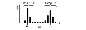
- a histogram in which the horizontal axis is the height of the resistance heating element precursor 66 and the vertical axis is the frequency.
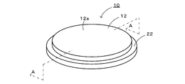
- FIG. 1 is a perspective view of the electrostatic chuck heater 10 of the present embodiment
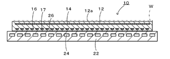
- FIG. 2 is a cross-sectional view taken along the line AA of FIG. 1
- FIG. 3 is an explanatory view when the resistance heating element 16 is viewed in a plan view
- FIG. 4 is FIG. BB sectional view.
- the electrostatic chuck heater 10 has an electrostatic electrode 14 and a resistance heating element 16 embedded inside a ceramic substrate 12.
- a cooling plate 22 is adhered to the back surface of the electrostatic chuck heater 10 via an adhesive layer 26.
- the ceramic substrate 12 is a disk made of ceramics (for example, made of alumina or aluminum nitride).
- a wafer mounting surface 12a on which the wafer W can be mounted is provided on the surface of the ceramic substrate 12.
- the electrostatic electrode 14 is a circular conductive thin film substantially parallel to the wafer mounting surface 12a.
- a rod-shaped terminal (not shown) is electrically connected to the electrostatic electrode 14.
- the rod-shaped terminal extends downward from the lower surface of the electrostatic electrode 14 through the ceramic substrate 12 and then through the cooling plate 22.
- the rod-shaped terminal is electrically insulated from the cooling plate 22.
- the portion of the ceramic substrate 12 above the electrostatic electrode 14 functions as a dielectric layer.
- Examples of the material of the electrostatic electrode 14 include tungsten carbide, metallic tungsten, molybdenum carbide, metallic molybdenum, and the like, and it is preferable to select one having a coefficient of thermal expansion close to that of the ceramic to be used.
- the resistance heating element 16 is a strip-shaped conductive line provided on a surface substantially parallel to the wafer mounting surface 12a.
- the strip-shaped conductive line is not particularly limited, but may be set to, for example, a width of 0.1 to 10 mm, a thickness of 0.001 to 0.1 mm, and a line-to-line distance of 0.1 to 5 mm.
- the resistance heating element 16 is wired from one terminal portion 18 to the other terminal portion 20 in a one-stroke manner so as not to intersect the strip-shaped conductive lines over the entire ceramic substrate 12.
- Power supply terminals (not shown) are individually electrically connected to the terminal portions 18 and 20 of the resistance heating element 16. These feeding terminals extend downward from the lower surface of the resistance heating element 16 through the ceramic substrate 12 and then through the cooling plate 22.
- these power supply terminals are electrically insulated from the cooling plate 22.
- the material of the resistance heating element 16 include tungsten carbide, metallic tungsten, molybdenum carbide, and metallic molybdenum, and it is preferable to select a material having a coefficient of thermal expansion close to that of the ceramic to be used.
- a concave groove 17 is provided on the surface of the resistance heating element 16 along the longitudinal direction (current flow direction) of the resistance heating element 16.
- the depth of the groove 17 is naturally smaller than the thickness of the resistance heating element 16, but it is preferably less than half the thickness of the resistance heating element 16.
- the side wall surface 17a of the groove 17 is inclined with respect to the wafer mounting surface 12a of the ceramic substrate 12. There is no gap between the side wall surface 17a of the groove 17 and the ceramic substrate 12.
- “there is no void” means that no void is confirmed when the SEM cross section of the ceramic substrate 12 having a magnification of 150 times is visually observed (the same applies hereinafter).
- the inclination angle ⁇ of the side wall surface 17a with respect to the wafer mounting surface 12a is preferably 27 ° or less. Further, the inclination angle ⁇ is preferably 10 ° or more in consideration of workability.
- the width of the concave groove 17 is preferably equal to or larger than the depth of the concave groove 17.
- the opening edge 17b of the groove 17 has a chamfered shape without being angular.
- the chamfer may be C chamfer or R chamfer.
- the end surface 16a of the resistance heating element 16 along the longitudinal direction is inclined with respect to the wafer mounting surface 12a of the ceramic substrate 12. There is no void between the end face 16a and the ceramic substrate 12.
- the inclination angle ⁇ of the end surface 16a with respect to the wafer mounting surface 12a is preferably 27 ° or less.
- the inclination angle ⁇ of the end surface 16a of the resistance heating element 16 is preferably smaller than the inclination angle ⁇ of the side wall surface 17a of the concave groove 17.
- the cooling plate 22 is made of metal (for example, made of aluminum) and has a built-in refrigerant passage 24 through which a refrigerant (for example, water) can pass.
- the refrigerant passage 24 is formed so that the refrigerant passes over the entire surface of the ceramic substrate 12.
- the refrigerant passage 24 is provided with a refrigerant supply port and a refrigerant discharge port (neither is shown).
- the wafer W is placed on the wafer mounting surface 12a of the electrostatic chuck heater 10, and a voltage is applied between the electrostatic electrode 14 and the wafer W to cause the wafer W to be placed on the wafer W by electrostatic force. Adsorbs to.
- the wafer W is subjected to plasma CVD film formation or plasma etching.
- the temperature of the wafer W is controlled to be constant by applying a voltage to the resistance heating element 16 to heat the wafer W or circulating the refrigerant through the refrigerant passage 24 of the cooling plate 22 to cool the wafer W. do.
- a voltage is applied between one terminal portion 18 and the other terminal portion 20 of the resistance heating element 16. Then, a current flows through the resistance heating element 16, which causes the resistance heating element 16 to generate heat and heat the wafer W.
- a concave groove 17 is formed on the surface of the resistance heating element 16.
- the resistance heating element 16 is divided into a plurality of sections from one terminal portion 18 to the other terminal portion 20, and the width of the concave groove 17 (depth is substantially constant) is determined for each section.
- the cross-sectional area of the resistance heating element 16 becomes small, so that the resistance becomes high and the amount of heat generated becomes large.
- the cross-sectional area of the resistance heating element 16 becomes large, so that the resistance becomes low and the amount of heat generated becomes small. Therefore, by adjusting the width of the concave groove 17 in each section, the calorific value of each section of the resistance heating element 16 is made to match the target calorific value.
- FIG. 5 is a manufacturing process diagram of the electrostatic chuck heater 10
- FIG. 6 is a cross-sectional view of the resistance heating element precursor 66 when the resistance heating element 66 is vertically cut on a surface including the width direction of the resistance heating element precursor 66.
- FIG. 7 is an explanatory view of a process of forming a groove 67 in the resistance heating element precursor 66
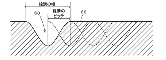
- FIGS. 8 and 9 show the resistance heating element precursor 66 vertically on a surface including the width direction of the resistance heating element precursor 66. It is sectional drawing of the wire groove 68 and the concave groove 67 when cut.
- an alumina substrate is manufactured as the ceramic substrate 12 will be described as an example.
- molded product (see FIG. 5 (A))
- Disk-shaped lower and upper molded bodies 51 and 53 are produced.
- a slurry containing an alumina powder for example, an average particle size of 0.1 to 10 ⁇ m
- a solvent for example, an average particle size of 0.1 to 10 ⁇ m
- a dispersant for example, an average particle size of 0.1 to 10 ⁇ m
- a gelling agent is put into a molding die, and gel is gelled in the molding die. It is prepared by chemically reacting an agent to gel a slurry and then releasing the slurry.
- the molded bodies 51 and 53 thus obtained are referred to as mold cast molded bodies.
- the solvent is not particularly limited as long as it dissolves the dispersant and the gelling agent, and is, for example, a hydrocarbon solvent (toluene, xylene, solvent naphtha, etc.), an ether solvent (ethylene glycol monoethyl ether, butyl).
- a hydrocarbon solvent toluene, xylene, solvent naphtha, etc.
- an ether solvent ethylene glycol monoethyl ether, butyl
- a solvent having two or more ester bonds such as a polybasic acid ester (for example, dimethyl glutarate) and an acid ester for a polyhydric alcohol (for example, triacetin).
- the dispersant is not particularly limited as long as it uniformly disperses the alumina powder in the solvent.
- Examples include copolymers.
- the gelling agent may contain, for example, isocyanates, polyols and a catalyst.
- isocyanates are not particularly limited as long as they are substances having an isocyanate group as a functional group, and examples thereof include tolylene diisocyanate (TDI), diphenylmethane diisocyanate (MDI), and modified products thereof.
- TDI tolylene diisocyanate
- MDI diphenylmethane diisocyanate
- modified products thereof modified products thereof.
- TDI tolylene diisocyanate
- MDI diphenylmethane diisocyanate
- a reactive functional group other than the isocyanate group may be contained, and further, a large number of reactive functional groups such as polyisocyanate may be contained.
- the polyols are not particularly limited as long as they are substances having two or more hydroxyl groups that can react with isocyanate groups, and for example, ethylene glycol (EG), polyethylene glycol (PEG), propylene glycol (PG), polypropylene glycol (PPG). , Polytetramethylene glycol (PTMG), polyhexamethylene glycol (PHMG), polyvinyl alcohol (PVA) and the like.
- the catalyst is not particularly limited as long as it is a substance that promotes the urethane reaction between isocyanates and polyols, and examples thereof include triethylenediamine, hexanediamine, and 6-dimethylamino-1-hexanol.
- a solvent and a dispersant are added to the alumina powder at a predetermined ratio, and these are mixed over a predetermined time to prepare a slurry precursor, and then gelation is performed on the slurry precursor. It is preferable to add an agent, mix and vacuum defoam to form a slurry.
- the mixing method for preparing the slurry precursor and the slurry is not particularly limited, and for example, a ball mill, a self-revolution type stirring, a vibration type stirring, a propeller type stirring and the like can be used.
- the chemical reaction (urethane reaction) of the gelling agent starts to proceed with the passage of time in the slurry in which the gelling agent is added to the slurry precursor, it is preferable to quickly pour it into the molding die.
- the slurry poured into the molding mold is gelled by a chemical reaction of the gelling agent contained in the slurry.
- the chemical reaction of the gelling agent is a reaction in which isocyanates and polyols undergo a urethane reaction to form a urethane resin (polyurethane).
- the slurry gels due to the reaction of the gelling agent, and the urethane resin functions as an organic binder.
- the degreasing temperature may be appropriately set according to the type of organic matter contained, but may be set to, for example, 400 to 600 ° C.
- the atmosphere may be an atmospheric atmosphere, an inert atmosphere, or a vacuum atmosphere.
- the calcined bodies 51 and 53 after degreasing are performed in order to increase the strength and facilitate handling.
- the calcination temperature is not particularly limited, but may be set to, for example, 750 to 900 ° C.
- the atmosphere may be an atmospheric atmosphere, an inert atmosphere, or a vacuum atmosphere.
- the resistance heating element precursor 66 is formed by printing a paste for a resistance heating element on one side of the lower calcined body 61 so as to have the same pattern as the resistance heating element 16 and then drying the paste.
- the electrostatic electrode precursor 64 is formed by printing an electrostatic electrode paste on one side of the upper calcined body 63 so as to have the same shape as the electrostatic electrode 14 and then drying the paste.
- Both pastes contain an alumina powder, a conductive powder, a binder, and a solvent.
- the alumina powder for example, the same ones used at the time of producing the molded bodies 51 and 53 can be used.
- the conductive powder include tungsten carbide powder.
- binder examples include a cellulose-based binder (ethyl cellulose and the like), an acrylic-based binder (polymethyl methacrylate and the like) and a vinyl-based binder (polyvinyl butyral and the like).
- solvent examples include terpineol and the like.
- the printing method include a screen printing method. Printing is performed multiple times. Therefore, each of the precursors 66 and 64 has a multi-layer structure. Further, the resistance heating element precursor 66 is printed so that the end face 66a along the longitudinal direction has a stepped shape (see FIG. 6). Since the end portion of the printed paste hangs down, the end surface 66a eventually becomes an inclined surface instead of a stepped surface.
- the end face 66a is inclined with respect to the surface of the lower calcined body 61, and the inclination angle ⁇ is preferably 45 ° or less.
- the electrostatic electrode precursor 64 is also printed in a stepped manner in the same manner as this. In this case as well, since the end portion of the printed paste hangs down, the end face will eventually become an inclined surface rather than a stepped surface.
- a concave groove 67 is formed in the resistance heating element precursor 66 provided on one side of the lower calcined body 61.
- the depth of the groove 67 is preferably less than half that of the resistance heating element precursor 66.
- the concave groove 67 is formed by the picosecond laser processing machine 30 shown in FIG. 7.
- the picosecond laser processing machine 30 forms the line groove 68 by irradiating the laser beam 32 along the longitudinal direction of the resistance heating element precursor 66 while driving the motor of the galvano mirror and the motor of the stage.
- the width of the line groove 68 (groove width formed by one pass) is not particularly limited, but is preferably 10 to 100 ⁇ m, more preferably 20 to 60 ⁇ m, for example.
- the picosecond laser processing machine 30 forms a concave groove 67 by providing a plurality of such line grooves 68 so as to overlap each other in the width direction of the resistance heating element precursor 66.
- the laser beam 32 has the highest energy at the center of the irradiation position, and the energy becomes lower toward the outside of the center. Therefore, the cross section of the generated line groove 68 has a shape close to a sine curve as shown in FIG.
- the pitch of the line groove 68 is set to be half the width of the line groove 68
- the cross section of the laser beam 32 when forming the next line groove 68 from the current line groove 68 is the dotted line in FIG.
- the cross section of the laser beam 32 when forming the line groove 68 is as shown by the alternate long and short dash line in FIG. 8
- the cross section of the laser beam 32 when forming the next line groove 68 is as shown by the alternate long and short dash line in FIG. Therefore, when all of these line grooves 68 have been formed, a concave groove 67 having a substantially flat bottom surface is obtained as shown in FIG.
- the concave groove 67 is an aggregate of the wire grooves 68.
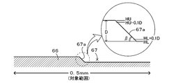
- the side wall surface 67a of the groove 67 is inclined with respect to the surface of the lower calcined body 61.
- the inclination angle ⁇ (see FIG. 9) of the side wall surface 67a of the recessed groove 67 with respect to the surface of the lower calcined body 61 is preferably 45 ° or less. Further, considering the workability of the laser beam 32, the inclination angle ⁇ is preferably 18 ° or more.
- the inclination angle ⁇ changes depending on the output of the laser beam 32 and the number of times the laser beam 32 is processed (the number of times the laser beam 32 irradiates the same portion). At this time, it is preferable that the inclination angle ⁇ is larger than the inclination angle ⁇ , in other words, the inclination angle ⁇ is gentler than the inclination angle ⁇ .
- the thickness distribution of the resistance heating element precursor 66 before forming the concave groove 67 is measured using a laser displacement meter. This measurement is performed at a plurality of predetermined measurement points along the center line of the resistance heating element precursor 66. At each measurement point, the difference (thickness difference) between the predetermined thickness target value and the thickness measurement value is obtained. The target value of the thickness is set based on the target value of the resistance when the resistance heating element precursor 66 is fired to obtain the resistance heating element 16. Then, based on the difference in thickness of a certain measurement point, the number of line grooves 68 formed in the section from the measurement point to the adjacent measurement point is determined. The depth of the wire groove 68 is a predetermined value.
- the concave groove 67 is formed so that the cross-sectional areas of the resistance heating element precursor 66 at the plurality of measurement points are each predetermined target cross-sectional areas.
- Alumina powder is laminated on the surface of the lower part of the calcined body 61 on which the resistance heating element precursor 66 is provided so as to cover the resistance heating element precursor 66, and the upper part of the calcined body 63 is electrostatically charged.
- a laminated body 50 is obtained by laminating and molding so that the surface on which the electrode precursor 64 is provided is in contact with the alumina powder.
- the laminated body 50 has a structure in which the alumina powder layer 62 is sandwiched between the upper and lower calcined bodies 61 and 63.
- the alumina powder the same ones used at the time of producing the molded bodies 51 and 53 can be used.
- Hot press firing (see FIG. 5 (F))
- the obtained laminate 50 is hot-press fired while applying pressure in the thickness direction.
- the laminated body 50 is compressed in the thickness direction because it is dammed by the mold so as not to spread in the radial direction.
- the compressibility varies depending on the press pressure, but is, for example, 30 to 70%.
- the resistance heating element 66 is fired to become the resistance heating element 16
- the electrostatic electrode precursor 64 is fired to become the electrostatic electrode 14
- the calcined bodies 61 and 63 and the alumina powder layer 62 are sintered. And integrated to form the ceramic substrate 12.
- the electrostatic chuck heater 10 is obtained.
- the press pressure is preferably 30 to 300 kgf / cm 2, and more preferably 50 to 250 kgf / cm 2 .
- the maximum temperature may be appropriately set depending on the type and particle size of the ceramic powder, but is preferably set in the range of 1000 to 2000 ° C.
- the atmosphere may be appropriately selected from the atmospheric atmosphere, the inert atmosphere, and the vacuum atmosphere.
- the electrostatic chuck heater 10 of the present embodiment corresponds to the ceramic heater of the present invention.
- the formation of the resistance heating element precursor of the present embodiment corresponds to the step (a) of the present invention, and the formation of the groove (FIGS. 5 (D) and 7 to 7 to 7). 9) corresponds to step (b)
- fabrication of the laminate corresponds to step (c)
- hot press firing corresponds to step (d).
- the calcined body 61 corresponds to the first ceramic fired layer
- the alumina powder layer 62 corresponds to the second ceramic unfired layer.
- the cross-sectional area of the resistance heating element precursor 66 (and thus the resistance of the resistance heating element 16) is adjusted by forming a concave groove 67 in the resistance heating element precursor 66.
- the concave groove 67 is formed so that the side wall surface 67a of the concave groove 67 is inclined with respect to the surface of the lower calcined body 61.
- the laminated body 50 is fired in a state where both are in close contact with each other.
- the electrostatic chuck heater 10 it is possible to prevent a gap from being generated between the side wall surface 17a of the concave groove 17 and the ceramic substrate 12, and the adhesive strength between the side wall surface 17a of the concave groove 17 and the ceramic substrate 12. Can be raised. Therefore, the thermal conductivity and heat equalizing property of the obtained electrostatic chuck heater 10 are improved.
- the inclination angle ⁇ of the side wall surface 67a of the concave groove 67 with respect to the surface of the calcined body 61 is 45 ° or less, the side wall surface 17a of the concave groove 17 of the resistance heating element 16 of the electrostatic chuck heater 10 and the ceramic substrate 12 It is possible to surely prevent the generation of a gap between the and.
- the inclination angle ⁇ is preferably 18 ° or more in consideration of workability (for example, the number of times of processing by laser light). If the inclination angle ⁇ is too small, the depth of the concave groove 17 formed by processing by one laser beam becomes shallow, so that the number of processings increases in order to make the concave groove 17 a predetermined depth. This is because it takes a long time.
- the concave groove 67 is formed so that the cross-sectional areas at the plurality of measurement points determined along the longitudinal direction of the resistance heating element precursor 66 each have a predetermined target cross-sectional area. Therefore, the shape of the groove 67 can be determined without measuring the resistance of the resistance heating element precursor 66.
- the depth of the recess 67 is preferably less than half the thickness of the resistance heating element precursor 66. By doing so, it becomes easier to prevent the generation of a gap between the side wall surface 17a of the concave groove 17 of the electrostatic chuck heater 10 and the ceramic substrate 12 as compared with the case where the depth of the concave groove 67 is too deep. ..
- the inclination angle ⁇ of the end surface of the resistance heating element precursor 66 with respect to the surface of the calcined body 61 along the longitudinal direction is 45 ° or less, the end surface 16a along the longitudinal direction of the resistance heating element 16 and the ceramic substrate 12 It is possible to surely prevent the generation of voids between them.
- the inclination angle ⁇ of the side wall 67a of the concave groove 67 is made larger than the inclination angle ⁇ of the end face 66a of the resistance heating element precursor 66, in other words, the inclination angle ⁇ . Is preferably gentler than the tilt angle ⁇ .
- the height of the resistance heating element precursor 66 is larger than the depth of the recess 67. Therefore, by making the inclination of the end face 66a of the resistance heating element precursor 66 gentler, a gap is generated between the end face 16a of the resistance heating element 16 of the electrostatic chuck heater 10 and the ceramic substrate 12. It can be prevented from doing so.
- the side wall surface 17a of the concave groove 17 is inclined with respect to the surface of the ceramic substrate 12, and there is no gap between the side wall surface 17a of the concave groove 17 and the ceramic substrate 12. .. Therefore, the thermal conductivity and heat equalizing property of the electrostatic chuck heater 10 are improved.
- the inclination angle ⁇ of the side wall surface 17a of the concave groove 17 with respect to the surface of the ceramic substrate 12 is preferably 27 ° or less. Further, the inclination angle ⁇ is preferably 10 ° or more. In order to more reliably prevent the generation of a gap between the side wall surface 17a of the concave groove 17 and the ceramic substrate 12, it is preferable to set the width of the concave groove 17 to be equal to or larger than the depth of the concave groove 17.
- the electrostatic chuck heater 10 has a chamfered shape at the opening edge 17b of the concave groove 17. Therefore, as compared with the case where the opening edge of the concave groove 17 is angular, cracks starting from the opening edge 17b of the concave groove 17 are less likely to occur. Even if the opening edge of the concave groove 67 before the hot press firing is angular, the opening edge 17b of the concave groove 17 after the hot press firing has a chamfered shape.
- the depth of the groove 17 is preferably not more than half the thickness of the resistance heating element 16.
- the end surface 16a along the longitudinal direction of the resistance heating element 16 is inclined with respect to the surface of the ceramic substrate 12, and there is no void between the end surface 16a and the ceramic substrate 12. .. Therefore, the thermal conductivity and the soaking property of the electrostatic chuck heater 10 are improved.
- the inclination angle ⁇ of the end surface 16a along the longitudinal direction of the resistance heating element 16 with respect to the surface of the ceramic substrate 12 is preferably 27 ° or less.
- the inclination angle ⁇ is preferably smaller than the inclination angle ⁇ of the side wall surface 17a of the concave groove 17.
- the electrostatic chuck heater 10 is exemplified as the ceramic heater, but a ceramic heater that does not have the electrostatic electrode 14 may be used.
- the laminated body 50 may be prepared by using the upper calcined body 63 having no electrostatic electrode precursor 64 and the laminated body 50 may be hot-press fired, or the upper calcined body 63 may be omitted. The laminate 50 may be produced and the laminate 50 may be hot-press fired.
- the alumina powder layer 62 is exemplified as the second ceramic unfired layer, but an alumina molded body layer or an alumina green sheet may be used instead of the alumina powder layer 62.
- an alumina molded body layer or an alumina green sheet may be used instead of the alumina powder layer 62.
- a dried one may be used, or a dried and degreased one may be used.
- the calcined body 61 is exemplified as the first ceramic fired layer, but an alumina sintered body may be used instead of the calcined body 61.
- a ceramic molded body layer or a ceramic green sheet may be used instead of the first ceramic fired layer.
- a dried one may be used, or one which has been dried and then degreased may be used.
- the resistance heating element precursor 66 forming the concave groove 67 a paste for a resistance heating element is printed and then dried, but a product that is printed and dried and then degreased, or a product that is printed and dried is used. After degreasing, it may be calcined (or fired).
- the resistance heating element 16 is wired on the entire ceramic substrate 12 so as not to intersect the strip-shaped conductive lines in a one-stroke manner, but the present invention is not particularly limited to this.
- the ceramic substrate 12 may be divided into a plurality of zones, and a resistance heating element may be provided in each zone so as not to intersect the strip-shaped conductive lines.
- each resistance heating element may adopt the same structure as the above-mentioned resistance heating element 16.
- Example 1 The electrostatic chuck heater 10 was manufactured according to the above-mentioned production example (see FIG. 5). [1] Preparation of molded product 100 parts by weight of alumina powder (average particle size 0.5 ⁇ m, purity 99.7%), 0.04 parts by weight of magnesia, 3 parts by weight of polycarboxylic acid copolymer as dispersant, as solvent 20 parts by weight of the polybasic acid ester was weighed and mixed with a ball mill (Trommel) for 14 hours to prepare a slurry precursor.
- alumina powder average particle size 0.5 ⁇ m, purity 99.7%
- magnesia 3 parts by weight of polycarboxylic acid copolymer as dispersant
- solvent 20 parts by weight of the polybasic acid ester was weighed and mixed with a ball mill (Trommel) for 14 hours to prepare a slurry precursor.
- a gelling agent that is, 4.3 parts by weight of 4,4'-diphenylmethane diisocyanate as isocyanates, 0.3 parts by weight of ethylene glycol as polyols, and 6-dimethylamino-1-hexanol as a catalyst. 0.1 part by weight was added and mixed with a self-revolving stirrer for 12 minutes to obtain a slurry.
- the obtained slurry was poured into a molding die. Then, by leaving it at 22 ° C. for 2 hours, the gelling agent was chemically reacted in the molding die to gel the slurry, and then the slurry was released.
- upper and lower molded bodies 51 and 53 see FIG. 5 (A) were obtained.
- the electrostatic electrode paste was screen-printed on one side of the upper calcined body 63 a plurality of times, and then dried to form the electrostatic electrode precursor 64 (see FIG. 5C).
- the inclination angle ⁇ of the end face 66a of the resistance heating element precursor 66 was 10 °. Since the end portion of the printed paste actually hangs down, the end surface 66a is not a stepped surface but an inclined surface. The inclination angle of the end face of the electrostatic electrode precursor 64 was also the same value.
- the height data interval was 1 ⁇ m.
- An example of the histogram is shown in FIG.
- the first group is the height group of the bottom surface of the concave groove 67
- the second group is the height group of the top surface (the portion where the concave groove 67 is not provided) of the resistance heating element precursor 66. ..
- the highest frequency value (mode) in the first group is regarded as the bottom height HL of the groove 67
- the highest frequency value (mode) in the second group is the resistance heating element precursor. It was regarded as the top height HU of the body 66.
- the value obtained by subtracting HL from HU was defined as the depth D of the concave groove 67. Then, the value obtained by adding 0.1D to HL was set as the lower limit value, and the value obtained by subtracting 0.1D from HU was set as the upper limit value, and the measurement was performed at a pitch of 2.5 ⁇ m between the lower limit value and the upper limit value of the side wall surface 67a.
- the regression line of the side wall surface 67a was obtained using the height, and the angle formed by the regression line with the horizontal line (horizontal axis in FIG. 10) was defined as the inclination angle ⁇ .
- the inclination angle ⁇ of the end face 66a of the above-mentioned resistance heating element precursor 66 was also obtained in the same manner. However, when determining the inclination angle ⁇ , the target range was set to 1.5 mm instead of 0.5 mm.
- Hot press firing The obtained laminate 50 was hot press fired. As a result, the resistance heating element precursor 66 is fired to become a resistance heating body 16 having a thickness of 50 ⁇ m, and the electrostatic electrode precursor 64 is fired to become an electrostatic electrode 14, and the calcined bodies 61, 63 and the alumina powder layer are formed. 62 was sintered and integrated to form a ceramic substrate 12, and an electrostatic chuck heater 10 was obtained. Hot press firing was carried out in a vacuum atmosphere at a pressure of 250 kgf / cm 2 and a maximum temperature of 1600 ° C. for 2 hours. Then, the surface of the ceramic sintered body was subjected to surface grinding with a diamond grindstone, and the thickness from the electrostatic electrode 14 to the wafer mounting surface 12a was set to 350 ⁇ m.
- Example 2 The electrostatic chuck heater 10 was manufactured in the same manner as in Example 1 except that the number of times of processing under the laser processing conditions of Example 1 was set to 1.
- the depth of the groove 67 of the resistance heating element precursor 66 is 10 ⁇ m
- the inclination angle ⁇ is 18 °
- the inclination angle ⁇ of the end face 66a of the resistance heating element precursor 66 and the inclination angle of the end face of the electrostatic electrode precursor 64 are 10. It was °.
- Example 3 The electrostatic chuck heater 10 was produced in the same manner as in Example 1 except that the number of times of processing under the laser processing conditions of Example 1 was set to 3 times.
- the depth of the groove 67 of the resistance heating element precursor 66 is 30 ⁇ m
- the inclination angle ⁇ is 45 °
- the inclination angle ⁇ of the end face 66a of the resistance heating element precursor 66 and the inclination angle of the end face of the electrostatic electrode precursor 64 are 10. It was °.
- Table 1 shows the main results of Examples 1 to 3.
- Example 4 the electrostatic chuck heater 10 was produced in the same manner as in Example 1 described above, except that the inclination angle ⁇ of the end face 66a was set to 18 °. The inclination angle ⁇ of the end face 16a along the longitudinal direction of the obtained resistance heating element 16 was 10 °.
- Example 5 the electrostatic chuck heater 10 was produced in the same manner as in Example 1 described above, except that the inclination angle ⁇ of the end face 66a was set to 45 °. The inclination angle ⁇ of the end face 16a along the longitudinal direction of the obtained resistance heating element 16 was 26 °.
- no voids (accompanying abnormal heat equalization) were confirmed in the vicinity of the end face 16a of the resistance heating element 16.
- the ceramic heater of the present invention can be used, for example, as a member for a semiconductor manufacturing apparatus.
- electrostatic chuck heater 10 electrostatic chuck heater, 12 ceramic substrate, 12a wafer mounting surface, 14 electrostatic electrode, 16 resistance heating element, 16a end surface, 17 concave groove, 17a side wall surface, 17b opening edge, 18, 20 terminal part, 22 cooling plate , 24 refrigerant passage, 26 adhesive layer, 30 picosecond laser processing machine, 32 laser light, 50 laminated body, 51, 53 molded body, 61, 63 calcined body, 62 alumina powder layer, 64 electrostatic electrode precursor, 66 resistance heating element precursor, 66a end face, 67 concave groove, 67a side wall surface, 68 wire groove.
Landscapes
- Engineering & Computer Science (AREA)
- Chemical & Material Sciences (AREA)
- Ceramic Engineering (AREA)
- Inorganic Chemistry (AREA)
- Manufacturing & Machinery (AREA)
- Resistance Heating (AREA)
- Surface Heating Bodies (AREA)
Priority Applications (4)
| Application Number | Priority Date | Filing Date | Title |
|---|---|---|---|
| CN202180007497.8A CN115152321B (zh) | 2020-02-26 | 2021-02-22 | 陶瓷加热器及其制法 |
| KR1020227027432A KR102814495B1 (ko) | 2020-02-26 | 2021-02-22 | 세라믹 히터 및 그 제법 |
| JP2022503599A JP7349010B2 (ja) | 2020-02-26 | 2021-02-22 | セラミックヒータ及びその製法 |
| US17/816,022 US20220369425A1 (en) | 2020-02-26 | 2022-07-29 | Ceramic heater and method of manufacturing the ceramic heater |
Applications Claiming Priority (2)
| Application Number | Priority Date | Filing Date | Title |
|---|---|---|---|
| JP2020030724 | 2020-02-26 | ||
| JP2020-030724 | 2020-02-26 |
Related Child Applications (1)
| Application Number | Title | Priority Date | Filing Date |
|---|---|---|---|
| US17/816,022 Continuation US20220369425A1 (en) | 2020-02-26 | 2022-07-29 | Ceramic heater and method of manufacturing the ceramic heater |
Publications (1)
| Publication Number | Publication Date |
|---|---|
| WO2021172261A1 true WO2021172261A1 (ja) | 2021-09-02 |
Family
ID=77491054
Family Applications (1)
| Application Number | Title | Priority Date | Filing Date |
|---|---|---|---|
| PCT/JP2021/006588 Ceased WO2021172261A1 (ja) | 2020-02-26 | 2021-02-22 | セラミックヒータ及びその製法 |
Country Status (6)
| Country | Link |
|---|---|
| US (1) | US20220369425A1 (https=) |
| JP (1) | JP7349010B2 (https=) |
| KR (1) | KR102814495B1 (https=) |
| CN (1) | CN115152321B (https=) |
| TW (1) | TWI768726B (https=) |
| WO (1) | WO2021172261A1 (https=) |
Citations (3)
| Publication number | Priority date | Publication date | Assignee | Title |
|---|---|---|---|---|
| JP2002190373A (ja) * | 2000-12-19 | 2002-07-05 | Ibiden Co Ltd | セラミックヒータの製造方法 |
| JP2006054125A (ja) * | 2004-08-12 | 2006-02-23 | Kyocera Corp | ヒータとその製造方法、及びこれを用いたウェハ加熱装置 |
| JP2006228633A (ja) * | 2005-02-18 | 2006-08-31 | Ngk Insulators Ltd | 基板加熱装置の製造方法及び基板加熱装置 |
Family Cites Families (8)
| Publication number | Priority date | Publication date | Assignee | Title |
|---|---|---|---|---|
| JP4794140B2 (ja) * | 2004-05-26 | 2011-10-19 | 京セラ株式会社 | ヒータとウェハ加熱装置及びその製造方法 |
| KR101098798B1 (ko) * | 2004-05-26 | 2011-12-26 | 쿄세라 코포레이션 | 히터와 웨이퍼 가열장치 및 히터의 제조방법 |
| CN100536621C (zh) * | 2004-05-27 | 2009-09-02 | 京瓷株式会社 | 陶瓷加热器和采用其的氧传感器及烫发剪 |
| JP4476701B2 (ja) | 2004-06-02 | 2010-06-09 | 日本碍子株式会社 | 電極内蔵焼結体の製造方法 |
| JP3969438B2 (ja) * | 2005-04-21 | 2007-09-05 | 株式会社村田製作所 | セラミック基板およびセラミック基板の製造方法 |
| CN201059302Y (zh) * | 2007-02-09 | 2008-05-14 | 江苏武进液压启闭机有限公司 | 带内置式行程检测装置的液压缸的陶瓷活塞杆 |
| JP5458050B2 (ja) * | 2011-03-30 | 2014-04-02 | 日本碍子株式会社 | 静電チャックの製法 |
| JP6054169B2 (ja) * | 2012-02-17 | 2016-12-27 | 日本碍子株式会社 | セラミックス素子の製造方法 |
-
2021
- 2021-02-22 CN CN202180007497.8A patent/CN115152321B/zh active Active
- 2021-02-22 WO PCT/JP2021/006588 patent/WO2021172261A1/ja not_active Ceased
- 2021-02-22 JP JP2022503599A patent/JP7349010B2/ja active Active
- 2021-02-22 KR KR1020227027432A patent/KR102814495B1/ko active Active
- 2021-02-23 TW TW110106266A patent/TWI768726B/zh active
-
2022
- 2022-07-29 US US17/816,022 patent/US20220369425A1/en active Pending
Patent Citations (3)
| Publication number | Priority date | Publication date | Assignee | Title |
|---|---|---|---|---|
| JP2002190373A (ja) * | 2000-12-19 | 2002-07-05 | Ibiden Co Ltd | セラミックヒータの製造方法 |
| JP2006054125A (ja) * | 2004-08-12 | 2006-02-23 | Kyocera Corp | ヒータとその製造方法、及びこれを用いたウェハ加熱装置 |
| JP2006228633A (ja) * | 2005-02-18 | 2006-08-31 | Ngk Insulators Ltd | 基板加熱装置の製造方法及び基板加熱装置 |
Also Published As
| Publication number | Publication date |
|---|---|
| KR102814495B1 (ko) | 2025-05-30 |
| JPWO2021172261A1 (https=) | 2021-09-02 |
| JP7349010B2 (ja) | 2023-09-21 |
| KR20220124779A (ko) | 2022-09-14 |
| TWI768726B (zh) | 2022-06-21 |
| TW202136172A (zh) | 2021-10-01 |
| US20220369425A1 (en) | 2022-11-17 |
| CN115152321A (zh) | 2022-10-04 |
| CN115152321B (zh) | 2025-12-19 |
Similar Documents
| Publication | Publication Date | Title |
|---|---|---|
| KR101982446B1 (ko) | 정전 척의 제법 및 정전 척 | |
| KR101891930B1 (ko) | 세라믹 히터 및 그 제법 | |
| TWI575634B (zh) | Ceramic heater, heater electrode and ceramic heater system | |
| US9630380B2 (en) | Method for manufacturing alumina sintered body and alumina sintered body | |
| JP6496675B2 (ja) | 静電チャックヒータ | |
| KR102373076B1 (ko) | 반도체 제조 장치용 부재, 그 제조법 및 성형형 | |
| US12557183B2 (en) | Ceramic heater and method of manufacturing the ceramic heater | |
| JP7349010B2 (ja) | セラミックヒータ及びその製法 | |
| CN114180942A (zh) | 复合烧结体、半导体制造装置构件及复合烧结体的制造方法 | |
| CN114390733A (zh) | 陶瓷加热器 |
Legal Events
| Date | Code | Title | Description |
|---|---|---|---|
| 121 | Ep: the epo has been informed by wipo that ep was designated in this application |
Ref document number: 21759987 Country of ref document: EP Kind code of ref document: A1 |
|
| ENP | Entry into the national phase |
Ref document number: 2022503599 Country of ref document: JP Kind code of ref document: A |
|
| ENP | Entry into the national phase |
Ref document number: 20227027432 Country of ref document: KR Kind code of ref document: A |
|
| NENP | Non-entry into the national phase |
Ref country code: DE |
|
| 122 | Ep: pct application non-entry in european phase |
Ref document number: 21759987 Country of ref document: EP Kind code of ref document: A1 |