WO2021172077A1 - カーボンナノチューブ集合体の製造方法 - Google Patents
カーボンナノチューブ集合体の製造方法 Download PDFInfo
- Publication number
- WO2021172077A1 WO2021172077A1 PCT/JP2021/005570 JP2021005570W WO2021172077A1 WO 2021172077 A1 WO2021172077 A1 WO 2021172077A1 JP 2021005570 W JP2021005570 W JP 2021005570W WO 2021172077 A1 WO2021172077 A1 WO 2021172077A1
- Authority
- WO
- WIPO (PCT)
- Prior art keywords
- unit
- gas
- base material
- catalyst
- growth
- Prior art date
- Legal status (The legal status is an assumption and is not a legal conclusion. Google has not performed a legal analysis and makes no representation as to the accuracy of the status listed.)
- Ceased
Links
Images



Classifications
-
- C—CHEMISTRY; METALLURGY
- C01—INORGANIC CHEMISTRY
- C01B—NON-METALLIC ELEMENTS; COMPOUNDS THEREOF; METALLOIDS OR COMPOUNDS THEREOF NOT COVERED BY SUBCLASS C01C
- C01B32/00—Carbon; Compounds thereof
- C01B32/15—Nano-sized carbon materials
- C01B32/158—Carbon nanotubes
- C01B32/16—Preparation
- C01B32/162—Preparation characterised by catalysts
-
- B—PERFORMING OPERATIONS; TRANSPORTING
- B01—PHYSICAL OR CHEMICAL PROCESSES OR APPARATUS IN GENERAL
- B01J—CHEMICAL OR PHYSICAL PROCESSES, e.g. CATALYSIS OR COLLOID CHEMISTRY; THEIR RELEVANT APPARATUS
- B01J19/00—Chemical, physical or physico-chemical processes in general; Their relevant apparatus
- B01J19/18—Stationary reactors having moving elements inside
- B01J19/20—Stationary reactors having moving elements inside in the form of helices, e.g. screw reactors
-
- C—CHEMISTRY; METALLURGY
- C01—INORGANIC CHEMISTRY
- C01B—NON-METALLIC ELEMENTS; COMPOUNDS THEREOF; METALLOIDS OR COMPOUNDS THEREOF NOT COVERED BY SUBCLASS C01C
- C01B32/00—Carbon; Compounds thereof
- C01B32/15—Nano-sized carbon materials
- C01B32/158—Carbon nanotubes
- C01B32/16—Preparation
- C01B32/164—Preparation involving continuous processes
-
- C—CHEMISTRY; METALLURGY
- C01—INORGANIC CHEMISTRY
- C01B—NON-METALLIC ELEMENTS; COMPOUNDS THEREOF; METALLOIDS OR COMPOUNDS THEREOF NOT COVERED BY SUBCLASS C01C
- C01B2202/00—Structure or properties of carbon nanotubes
- C01B2202/08—Aligned nanotubes
-
- C—CHEMISTRY; METALLURGY
- C01—INORGANIC CHEMISTRY
- C01B—NON-METALLIC ELEMENTS; COMPOUNDS THEREOF; METALLOIDS OR COMPOUNDS THEREOF NOT COVERED BY SUBCLASS C01C
- C01B2202/00—Structure or properties of carbon nanotubes
- C01B2202/20—Nanotubes characterized by their properties
- C01B2202/32—Specific surface area
-
- C—CHEMISTRY; METALLURGY
- C01—INORGANIC CHEMISTRY
- C01B—NON-METALLIC ELEMENTS; COMPOUNDS THEREOF; METALLOIDS OR COMPOUNDS THEREOF NOT COVERED BY SUBCLASS C01C
- C01B2202/00—Structure or properties of carbon nanotubes
- C01B2202/20—Nanotubes characterized by their properties
- C01B2202/34—Length
-
- C—CHEMISTRY; METALLURGY
- C01—INORGANIC CHEMISTRY
- C01B—NON-METALLIC ELEMENTS; COMPOUNDS THEREOF; METALLOIDS OR COMPOUNDS THEREOF NOT COVERED BY SUBCLASS C01C
- C01B2202/00—Structure or properties of carbon nanotubes
- C01B2202/20—Nanotubes characterized by their properties
- C01B2202/36—Diameter
-
- C—CHEMISTRY; METALLURGY
- C01—INORGANIC CHEMISTRY
- C01P—INDEXING SCHEME RELATING TO STRUCTURAL AND PHYSICAL ASPECTS OF SOLID INORGANIC COMPOUNDS
- C01P2006/00—Physical properties of inorganic compounds
- C01P2006/11—Powder tap density
-
- C—CHEMISTRY; METALLURGY
- C01—INORGANIC CHEMISTRY
- C01P—INDEXING SCHEME RELATING TO STRUCTURAL AND PHYSICAL ASPECTS OF SOLID INORGANIC COMPOUNDS
- C01P2006/00—Physical properties of inorganic compounds
- C01P2006/12—Surface area
-
- C—CHEMISTRY; METALLURGY
- C01—INORGANIC CHEMISTRY
- C01P—INDEXING SCHEME RELATING TO STRUCTURAL AND PHYSICAL ASPECTS OF SOLID INORGANIC COMPOUNDS
- C01P2006/00—Physical properties of inorganic compounds
- C01P2006/80—Compositional purity
Definitions
- the present invention relates to a method for producing a carbon nanotube aggregate, and more particularly to a method for producing a high-quality carbon nanotube aggregate having a specific surface area of 600 m 2 / g or more.
- Nanocarbon materials such as carbon nanotubes (hereinafter, may be referred to as "CNT") have been attracting attention as materials having excellent conductivity, thermal conductivity, and mechanical properties. Nanocarbon materials were generally more expensive than other materials due to their high manufacturing costs, although they were recognized to be capable of exhibiting superior properties.
- Patent Document 1 the formation step of reducing the catalyst in a reducing gas atmosphere and the growth step of growing CNTs on the catalyst in a raw material gas atmosphere are prevented from being mixed with each other.
- a manufacturing method for manufacturing CNTs is being studied. From the viewpoint of increasing production efficiency, it is advantageous that the base material has a large surface area per volume such as powder, but when the powdered base material is conveyed by the belt conveyor method, the stirring of the base material is insufficient. Therefore, there is a problem that CNT growth unevenness between the base materials becomes remarkable.
- production of nanocarbons comprises moving the catalyst body by stirring using a transport means such as a belt conveyor in a reaction tube provided with a catalyst activation zone, a nanocarbon synthesis zone, and a cooling zone.
- a transport means such as a belt conveyor in a reaction tube provided with a catalyst activation zone, a nanocarbon synthesis zone, and a cooling zone.
- the method is being considered.
- the atmospheric gas in each zone cannot be spatially separated, it can be dealt with by temporally switching between the reducing gas and the raw material gas, or mixing of each gas is allowed, and the height is as high as that of single-walled carbon nanotubes. It has not been possible to continuously produce high-quality nanocarbons.
- Patent Document 3 a method for producing nanocarbon, which comprises continuously supplying a hydrocarbon and a catalyst by a screw feeder so as to be in contact with each other in a countercurrent or countercurrent state, has been studied.
- methane is used as the hydrocarbon of the raw material gas.
- the catalytic reduction step is not always necessary and it is not necessary to divide the inside of the reaction tube into zones, but mainly multi-walled carbon nanotubes are synthesized and the growth rate. Because it is slow, it has not been possible to continuously produce high-quality nanocarbons such as single-walled carbon nanotubes with high production efficiency.
- Japanese Patent No. 5471959 Japanese Unexamined Patent Publication No. 2011-241104 Japanese Patent No. 5285730
- an object of the present invention is to provide a method for producing a carbon nanotube aggregate, which can efficiently produce a high quality carbon nanotube aggregate.
- the present inventors have conducted diligent studies for the purpose of solving the above problems. As a result, in the production of the CNT aggregate, the present inventors separately carry out the formation step and the growth step in this order, and in these steps, the substrate having the catalyst on the surface is conveyed by screw rotation. By doing so, we have newly found that it is possible to efficiently produce high-quality CNT aggregates, and completed the present invention.
- the present invention aims to advantageously solve the above problems, and the CNT aggregate production method of the present invention has a specific surface area of 600 m 2 / g or more on a substrate having a catalyst on the surface.
- a formation unit for producing carbon nanotube aggregates for growing carbon nanotube aggregates which realizes a formation step in which the ambient environment of the catalyst is a reducing gas environment and at least one of the catalyst and the reducing gas is heated.
- a connecting portion that spatially connects the inner space and the inner space of the growth unit, a first conveying unit that conveys the base material by screw rotation in the inner space of the formation unit, and the above. It is a second transport unit that transports the base material by screw rotation in the furnace space of the growth unit, and the first transport unit and the second transport unit are one common unit and / or separate.
- a gas that prevents gas from being mixed with each other between the first and second transfer units configured as units, the in-core space of the formation unit, and the in-core space of the growth unit.
- the formation step and the growth step are carried out while continuously transporting the base material and preventing the gas environment in each step from being mixed with each other by using a mixing prevention device and a manufacturing device having the same. It is characterized by According to such a manufacturing method, high-quality CNT aggregates can be efficiently produced.
- the formation unit and the growth unit are separate constituent parts and are connected in series by the connecting part. According to such a manufacturing method, the conditions in each of the formation step and the growth step can be easily optimized, and the quality of the obtained CNT aggregate and the production efficiency of the CNT aggregate can be further improved.
- the gas mixing prevention device controls the air flow, so that the gas is between the in-fire space of the formation unit and the in-fire space of the growth unit. It is preferable that the two are prevented from being mixed with each other. According to such a manufacturing method, the reduction of the catalyst in the formation step is less likely to be hindered, and the quality of the obtained CNT aggregate and the production efficiency of the CNT aggregate can be further improved.
- the base material conveyed by the first transfer unit and the reducing gas flow countercurrently and the reducing gas.
- the reducing gas is continuously supplied so as to come into contact with each other in a countercurrent state, and is conveyed by the second transfer unit in the furnace space of the growth unit in the growth step. It is preferable to carry out at least one of the continuous supply of the raw material gas so that the base material and the raw material gas come into contact with each other in a countercurrent and countercurrent state. According to such a manufacturing method, the quality of the obtained CNT aggregate and the production efficiency of the CNT aggregate can be further improved.
- the raw material gas environment in the growth step is a high carbon concentration environment and contains a catalyst activator.
- the CNTs can be grown while maintaining the catalytic activity for a long period of time. The production efficiency of the CNT aggregate can be further improved.
- the raw material gas environment contains ethylene and carbon dioxide as a catalyst activator.
- the base material is particles having an apparent density of 2.0 g / cm 3 or more. If the base material is particles having an apparent density of 2.0 g / cm 3 or more, the obtained CNT aggregate can be lengthened.
- the "apparent density" of the support means the mass per unit volume including the voids when the support is particles having voids (closed pores) inside. The "apparent density of the support” can be measured according to the pycnometer method.
- the base material contains one or more elements of Al, Si, and Zr.
- the production efficiency of the CNT aggregate can be further improved.
- the catalyst layer forming step of forming the catalyst layer on the base material and the carbon nanotube aggregate are separated from the base material, and the base material and the carbon nanotube aggregate are separated. It is preferable to include a separation and recovery step of recovering the base material, and a reuse step of making the base material reusable by oxidizing and removing the recovered carbon on the base material. By carrying out such a separation / recovery step and a reuse step, the production efficiency of the CNT aggregate can be further improved.
- the method for producing a CNT aggregate of the present invention is a method for growing a CNT aggregate having a specific surface area of 600 m 2 / g or more on a substrate having a catalyst on its surface. Then, in the method for producing a CNT aggregate of the present invention, the gas environment in each of the following steps is mixed with each other while continuously transporting the base material using a CNT manufacturing apparatus having the following components. It is a method of carrying out the formation process and the growth process while preventing it.
- -A formation unit that realizes a formation process in which the ambient environment of the catalyst is a reducing gas environment and at least one of the catalyst and the reducing gas is heated.
- the environment around the catalyst is a raw material gas environment and at least one of the catalyst and the raw material gas.
- a growth unit that realizes a growth process that grows carbon nanotube aggregates by heating
- the first transport unit that transports the base material by screw rotation and the second transport unit that transports the base material by screw rotation in the space inside the furnace of the growth unit.
- Gas can be implemented between the furnace space of the first and second transport units-formation units and the furnace space of the growth unit, which can be mounted as one common unit and / or separate units.
- Gas mixing prevention device that prevents mutual mixing
- the base material constituting the base material having a catalyst on the surface used in the production method of the present invention can be formed by supporting the catalyst on the base material.
- the base material is a member capable of supporting a catalyst for synthesizing CNTs on the surface thereof, and a member made of any material can be used without particular limitation.
- the base material is made of a ceramic material containing any one or more elements of Al, Si, and Zr.
- the base material is preferably made of a metal oxide containing any one or more of Al, Si, and Zr, and more preferably zirconium dioxide (ZrO 2 ).
- the shape of the base material is preferably particulate with an aspect ratio of less than 5.
- the "aspect ratio" of the base particle can be obtained as an average value by calculating a value (width orthogonal to the major axis / major axis) of a plurality of arbitrarily selected particles on a microscope image.
- the substrate particle is preferably an apparent density of 2.0 g / cm 3 or more, preferably 3.8 g / cm 3 or more, more preferably 5.8 g / cm 3 or more, 8 It is preferably 0.0 g / cm 3 or less.
- the base material particles are excellent in handleability and the production efficiency of the CNT aggregate can be further improved.
- the particle size of the base particles is preferably 0.05 mm or more, more preferably 0.3 mm or more, more preferably 10 mm or less, still more preferably 2 mm or less, still more preferably 1 mm or less.
- the particle size of the base particles is equal to or greater than the above lower limit value, the obtained CNT aggregate can be lengthened.
- the particle size of the base particles is not more than the above upper limit value, the production efficiency of the CNT aggregate can be further improved.
- the "particle size" of the base particle means the volume average particle size D50.
- the volume average particle size D50 represents a particle size in which the cumulative volume calculated from the small diameter side in the particle size distribution (volume basis) measured by the laser diffraction method for the base particles is 50%.
- the catalyst supported on the base material is not particularly limited, and examples thereof include catalyst components such as nickel (Ni), iron (Fe), cobalt (Co), and molybdenum (Mo). Above all, from the viewpoint of further enhancing the production efficiency of the CNT aggregate, it is preferable that the catalyst component contains at least one kind of metal such as nickel (Ni), iron (Fe), cobalt (Co), and molybdenum (Mo). Further, optionally, as a base layer for supporting the catalyst on the base material, a base layer formed of a material such as aluminum oxide, titanium oxide, titanium nitride, or silicon oxide can be provided.
- the method of supporting the catalyst (or catalyst layer) on the surface of the base material is not particularly limited, and any existing method can be adopted.
- the base material particles are used as the base material, it is preferable to use a rotary drum type coating device provided with a substantially cylindrical rotary drum.
- the base material is arranged in a substantially cylindrical rotating drum, and the rotating drum is rotated with the inclined axis as the rotation axis, so that the base material particles are agitated and the catalyst solution containing the above-mentioned catalyst component is contained.
- a solution containing components that can form the base layer and base material particles are used prior to spraying and drying the catalyst solution.
- the base material particles are centrifugally swirled and suspended in the vertical direction.
- One method includes a step of spraying the catalyst solution while flowing the particles.
- the reducing gas is a gas having at least one effect of reducing the catalyst, promoting the atomization of the catalyst, and improving the activity of the catalyst.
- the reducing gas for example, hydrogen gas, ammonia, water vapor, and a mixed gas thereof can be applied.
- a mixed gas obtained by mixing hydrogen gas with an inert gas such as helium gas, argon gas or nitrogen gas can also be used.
- the reducing gas is generally used in the formation step, but may be appropriately used in the growth step.
- Raw material gases used in the synthesis of CNT aggregates include, for example, hydrocarbons such as methane, ethane, ethylene, propane, butane, pentane, hexane, heptane propylene, and acetylene; lower alcohols such as methanol and ethanol; acetone and monoxide. Examples thereof include low carbon number oxygen-containing compounds such as carbon. In addition, these can also be used as a mixture of a plurality of types. Further, the raw material gas may be diluted with the inert gas as described above.
- the raw material gas contains ethylene.
- ethylene By heating ethylene in a predetermined temperature range (700 ° C. or higher and 900 ° C. or lower), the decomposition reaction of ethylene is promoted, and when the decomposition gas comes into contact with the catalyst, high-speed growth of CNTs becomes possible.
- the thermal decomposition time is too long, the decomposition reaction of ethylene proceeds too much, causing deactivation of the catalyst and adhesion of carbon impurities to the CNT aggregate.
- the thermal decomposition time is preferably in the range of 0.5 seconds or more and 10 seconds or less with respect to the range of ethylene concentration of 0.1% by volume or more and 40% by volume or less.
- the heating flow path volume is the volume of the flow path heated to a predetermined temperature T ° C. through which the raw material gas passes before coming into contact with the catalyst, and the raw material gas flow rate is a flow rate at 0 ° C. and 1 atm.
- a catalyst activator may be added in the CNT growth step. By adding the catalyst activator, the production efficiency and quality of the CNT aggregate can be further improved.
- the catalyst activator used here is generally a substance containing oxygen and may be a substance that does not cause a great deal of damage to CNT at the growth temperature. In addition to water, for example, hydrogen sulfide; oxygen, ozone, oxidation. Low-carbon oxygen-containing compounds such as nitrogen, carbon monoxide, and carbon dioxide; alcohols such as ethanol and methanol; ethers such as tetrahydrofuran; ketones such as acetone; aldehydes; esters; nitrogen oxide; and these. Examples include a mixture of.
- the CNTs in the growth step, by growing the CNTs in a high-concentration carbon environment containing a catalyst activator, the CNTs can be grown while maintaining the catalytic activity for a long period of time.
- the production efficiency of the CNT aggregate can be further improved.
- the raw material gas contains ethylene and the presence of carbon dioxide as a catalyst activator, the quality of the obtained CNT aggregate and the production efficiency of the CNT aggregate can be further improved. The reason is presumed to be as follows. First, in the CNT synthesis reaction, it has been found that ethylene has relatively low activity as a carbon source and carbon dioxide as a catalyst activator.
- the amount of the catalyst activator added in the growth step may be 0.5% by volume or more of the atmosphere in the growth step, preferably 4% by volume or more, and 5% by volume or more. More preferably, it is usually 40% by volume or less.
- the high carbon concentration environment means an atmosphere in which 0.1% by volume or more of the atmosphere in the growth process (hereinafter, also referred to as “raw material gas environment”) is the raw material gas.
- the ratio of the raw material gas in the high carbon concentration environment can be, for example, 40% by volume or less. Further, the ratio of the raw material gas in the high carbon concentration environment is preferably 4% by volume or more, more preferably 5% by volume or more, further preferably 10% by volume or more, and preferably 30% by volume or less.
- the catalytic activity is remarkably improved by including the catalyst activator in the raw material gas environment, the catalyst does not lose its activity even in a high carbon concentration environment, and the CNT aggregate can be grown for a long time. At the same time, the growth rate can be significantly improved.
- the reaction temperature for growing the CNT aggregate is not particularly limited, and may be, for example, 400 ° C. or higher and 1100 ° C. or lower. Further, when the raw material gas contains ethylene, it is preferably 700 ° C. or higher and 900 ° C. or lower.
- the formation step is a step of setting the ambient environment of the catalyst supported on the base material as a reducing gas environment and heating at least one of the catalyst and the reducing gas. By this step, at least one effect of reducing the catalyst, promoting fine particle formation in a state suitable for the growth of CNT of the catalyst, and improving the activity of the catalyst appears.
- the reducing gas is continuously produced in the furnace space of the formation unit so that the base material transported by the first transport unit and the reducing gas come into contact with each other in a countercurrent and countercurrent state. It is preferable to be supplied. According to such a manufacturing method, the quality of the obtained CNT aggregate and the production efficiency of the CNT aggregate can be further improved. More specifically, by bringing the base material transported by the first transport unit and the reducing gas into contact with each other in a countercurrent and countercurrent state, the base material is transported in the formation unit for a period of time. Since the base material and the reducing gas can be brought into contact with each other, the contact time between the two can be efficiently secured.
- the contact efficiency between the two can be improved by configuring the contact direction so that either the countercurrent or the countercurrent is realized instead of selecting one of the countercurrent and the countercurrent. Further, in such a configuration, by appropriately arranging the introduction position and the exhaust position of the reducing gas, it is possible to optimize the time for the reducing gas to stay in the manufacturing apparatus. This also makes it possible to further improve the quality of the obtained CNT aggregate and the production efficiency of the CNT aggregate.
- the temperature of the catalyst carrier or the reducing gas atmosphere in the formation step is preferably 400 ° C. or higher and 1100 ° C. or lower. Further, the execution time of the formation step can be 3 minutes or more and 120 minutes or less.
- the ambient environment of the catalyst which is in a state suitable for producing the CNT aggregate by the above-mentioned formation step, is set as the raw material gas environment, and at least one of the catalyst and the raw material gas is heated to CNT aggregate.
- the manufacturing method of the present invention is characterized in that both steps are carried out while continuously transporting the base material by screw rotation and preventing the gas environment in the formation step and the growth step from being mixed with each other. do. Thereby, the quality of the obtained CNT aggregate and the production efficiency of the CNT aggregate can be further improved.
- the base material and the raw material gas transported by the second transport unit come into contact with each other in the countercurrent and countercurrent states in the furnace space of the growth unit.
- the raw material gas is continuously supplied.
- the quality of the obtained CNT aggregate and the production efficiency of the CNT aggregate can be further improved.
- by appropriately arranging the introduction position and the exhaust position of the raw material gas it is possible to optimize the time for the raw material gas to stay in the manufacturing apparatus. This also makes it possible to further improve the quality of the obtained CNT aggregate and the production efficiency of the CNT aggregate.
- a cooling step can be performed after the growth step.
- the CNT aggregate, the catalyst, and the base material obtained in the growth step are cooled in an inert gas environment. Since the CNT aggregate, catalyst, and substrate after the growth step are in a high temperature state, they tend to be easily oxidized when placed in an oxygen-existing environment. Therefore, it is preferable to cool the CNT-aligned aggregate, the catalyst, and the substrate to 400 ° C. or lower, more preferably 200 ° C. or lower in an inert gas environment.
- the carbon nanotube aggregate is separated from the base material, and the base material and the carbon nanotube aggregate are recovered separately.
- the recovery method is not particularly limited, and any known method can be adopted. Among them, a separation and recovery method using an external force and a fluid flow as a drag of the external force (for example, an air vortex formed by a centrifugal force and an air flow as a drag of the centrifugal force) (for example, International Publication No. 2019 / 188979) is preferred.
- the base material is made reusable by oxidizing and removing carbon on the recovered base material.
- the oxidation removal method is not particularly limited, and examples thereof include a method of heating a base material while flowing air.
- the adsorption / desorption isotherm of liquid nitrogen at 77 K was measured for the CNT not subjected to the opening treatment, and from this adsorption / desorption isotherm curve, Brunauer, Emmett, Teller It is a value measured from the method of.
- the specific surface area of the CNT aggregate can be measured using a BET specific surface area measuring device compliant with JIS Z8830.
- the specific surface area of the CNTs obtained by the present invention is 600 m 2 / g or more, preferably 800 m 2 / g or more, preferably 2600 m 2 / g or less, and preferably 1400 m 2 / g or less. More preferred. Further, the opening-treated CNT aggregate preferably has a specific surface area of 1300 m 2 / g or more.
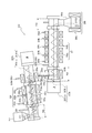
- FIG. 1 is a diagram for explaining a schematic configuration of an apparatus capable of carrying out the CNT aggregate manufacturing method according to an example of the present invention.
- the CNT assembly manufacturing apparatus 100 includes a formation unit 102, a growth unit 104, a transfer unit 107 that conveys a base material between the formation unit 102 and the growth unit 104, and the formation unit 102 and the growth unit 104.
- a connecting portion 108 that is spatially connected to each other and a gas mixing prevention device that prevents gas from being mixed with each other between the formation unit 102 and the growth unit 104 are provided.
- the CNT aggregate manufacturing apparatus 100 is arranged after the inlet purging device 101 arranged in the front stage of the formation unit 102, the outlet purging device 105 arranged in the rear stage of the growth unit 104, and further in the rear stage of the outlet purging device 105. It is provided with a component such as a cooling unit 106.
- the inlet purging device 101 includes a set of devices for preventing external air from entering the device furnace from the substrate inlet. It has a function of replacing the surrounding environment of the base material conveyed into the CNT aggregate manufacturing apparatus 100 with purge gas.
- a furnace or chamber for holding the purge gas, an injection device for injecting the purge gas, and the like can be mentioned.
- the purge gas is preferably an inert gas, and particularly preferably nitrogen from the viewpoint of safety, cost, purge property and the like.
- a small amount of hydrogen may be contained for the purpose of improving the catalytic activity.
- the purge gas injection device is mounted as a gas curtain device including an air supply device configured to be able to inject purge gas from above and below in a shower shape, and is mounted from the CNT aggregate manufacturing device 100 inlet. It is preferable that the structure is such that external air can be prevented from being mixed.
- the inlet purging device 101 is attached to a connecting portion 109 connecting the front chamber 113, which is a component for introducing a base material into the system via the hopper 112, and the formation furnace 102a. There is.
- the formation unit 102 includes a set of devices for realizing the formation process.
- the formation unit 102 has a function of using the surrounding environment of the catalyst formed on the surface of the base material as a reducing gas environment and heating at least one of the catalyst and the reducing gas.
- the formation unit 102 includes, for example, a formation furnace 102a for holding the reduction gas, a reduction gas injection device 102b for injecting the reduction gas, a heating device 102c for heating at least one of the catalyst and the reduction gas, and the inside of the furnace. It may be composed of an exhaust device 102d or the like that discharges gas to the outside of the system.
- the heating device 102c is not particularly limited, and may be mounted by, for example, a resistance heating heater, an infrared heating heater, an electromagnetic induction heater, or the like. Further, the heating device 102c can heat the inside of the system so that the temperature inside the formation furnace is 400 ° C. or higher and 1100 ° C. or lower. Furthermore, the exhaust device 102d is a component for exhausting the reduced gas in the furnace, including a reduced gas exhaust port arranged on the side surface of the furnace body of the formation furnace 102a.
- the formation unit 102 preferably includes at least one reduction gas exhaust port, and may include a plurality of reduction gas exhaust ports.
- the growth unit 104 includes a set of devices for realizing the growth process.
- the growth unit 104 uses the environment around the catalyst, which has been made suitable for producing the CNT aggregate by the formation step, as the raw material gas environment, and grows the CNT aggregate by heating at least one of the catalyst and the raw material gas. It has a function to make it.
- the growth unit 104 is a growth furnace 104a for maintaining the raw material gas environment, a raw material gas injection device 104b for injecting the raw material gas, and a heating device for heating at least one of the catalyst and the raw material gas. It may be composed of 104c, an exhaust device 104d or the like that discharges the gas in the furnace to the outside of the system.
- the heating device 104c is not particularly limited, and may be mounted by, for example, a resistance heating heater, an infrared heating heater, an electromagnetic induction heater, or the like. Further, although not shown, the growth unit 104 preferably includes a catalyst activator addition device. Further, the exhaust device 104d is a component for exhausting the raw material gas in the furnace to the outside of the system, including the raw material gas exhaust port arranged on the side surface of the furnace body of the growth furnace 104a. The growth unit 104 preferably includes at least one raw material gas exhaust port, and may include a plurality of growth units 104.
- each component having the same function as each component shown in FIG. 1 is designated by the same reference code as that used in FIG. Basically, it has the same function as each component shown in FIG. 1, but for components that are slightly different in terms of arrangement, etc., "'" is added to the same reference code as the reference code used in FIG. show.
- the growth furnace 104a shown in FIG. 2 is provided with a plurality of heating devices 104c', and has two raw material gas inlets G1 and G2 on the side surface of the furnace body and one in the gap between them, the front stage side and the rear stage stage in the substrate transport direction.
- a total of three raw material gas exhaust ports Ex1 to Ex3 are provided on each side.
- the two raw material gas inlets G1 and G2 flow in the forward and reverse directions with respect to the substrate transport direction according to the suction force caused by the exhaust from the raw material gas exhaust ports Ex1 to Ex3.
- the base material transported along the transport direction and the raw material gas come into contact with each other in a countercurrent and countercurrent state.
- the introduction speed and introduction balance of the raw material gas from the raw material gas introduction ports G1 and G2 and the exhaust speed and the exhaust balance at the raw material gas exhaust ports Ex1 to Ex3 the time for the raw material gas to stay in the system. Can be easily optimized.
- the quality of the obtained CNT aggregate and the production efficiency of the CNT aggregate can be further improved. Further, forming such a gas flow makes it possible to realize a function of preventing mutual gas mixing in the space in the furnace between adjacent units by controlling the air flow of the gas mixing prevention device 103.
- the growth unit has been described as a specific example in this description, the same control can be easily realized for the behavior of the reducing gas in the formation unit by applying the same configuration to the formation unit. ..
- the catalyst activator addition device comprises a set of devices for adding the catalyst activator to the raw material gas or directly adding the catalyst activator to the ambient environment of the catalyst in the space inside the growth furnace.
- the catalyst activator addition device is not particularly limited in order to supply the catalyst activator, but for example, supply by a bubbler, supply by vaporizing a solution containing a catalyst activator, and supply as a gas as it is.
- a supply system capable of liquefying and vaporizing the solid catalyst activator and supplying the solid catalyst activator.
- Such supply systems may include, for example, vaporizers, mixers, stirrers, diluters, atomizers, pumps, compressors and the like.
- a catalyst activator concentration measuring device may be provided in a catalyst activator supply pipe or the like. By feedback control using this output value, it is possible to supply a stable catalyst activator with little change over time.
- the transport unit 107 is a unit that continuously transports the base material 111 by screw rotation.
- the transport unit 107 may be mounted by a screw conveyor.
- the screw conveyor can be mounted by a drive device 107b such as a motor that can rotate the screw blades 107a and the screw blades to exert the substrate transporting ability.
- the base material can be introduced into the apparatus from outside the system via, for example, the hopper 112.
- the vicinity of the drive device 107b can be heated by the heating device 114 configured to be able to heat the inside of the system at a temperature lower than the heating temperature in the formation unit.
- the diameter, winding pitch, etc. of the screw blades constituting the screw conveyor can be arbitrarily adjusted according to the size of the base material to be used.
- the first transport unit that transports the base material by screw rotation in the furnace space of the formation unit 102 and the second transport unit that transports the base material by screw rotation in the furnace space of the growth unit 104 The configuration in which the transport unit is mounted by the screw blade 107a and the drive device 107b, which are one common unit, is shown in the figure. As will be described later with reference to FIG. 3, the first transfer unit and the second transfer unit can be mounted as separate units. Alternatively, it is possible that there are two individual transport units, the first transport unit is the first transport unit, and the second transport unit is one unit in which the first and second are common.
- the gas mixing prevention device 103 is installed at a connection portion 108 that spatially connects the formation unit 102 and the growth unit 104 to each other, and the gas is mutually mixed into the furnace space of the formation unit 102 and the growth unit 104. It consists of a set of devices to realize the function to prevent.
- the gas mixing prevention device 103 is not particularly limited, and is a gate valve device or a rotary valve device that can mechanically cut off the spatial connection of each unit except during the movement from the unit of the substrate to the unit.
- a gas curtain device composed of an air supply device configured to inject purge gas, and gas existing in the connection portion 108, the inside of the formation unit 102 in the vicinity of the connection portion 108, and the inside of the growth unit 104 in the vicinity of the connection portion 108. It can be mounted by an exhaust device that discharges to the outside of the system. Among them, the gas mixing prevention device 103 sucks at least one of the reducing gas flowing in from the formation unit 102 side and the raw material gas flowing in from the growth unit 104 side to form a CNT aggregate. It is preferable to have an exhaust device 103a that exhausts air to the outside of the manufacturing device 100.
- the gas mixing prevention device 103 also has a purge gas injection device 103b that injects purge gas (seal gas) along the opening surface of the connection portion 108, and the exhaust device 103a sucks the purge gas. It is preferable to exhaust the air to the outside of the manufacturing apparatus. According to the CNT aggregate manufacturing apparatus 100 having such a configuration, the reduction of the catalyst in the formation step is less likely to be hindered, and the quality of the obtained CNT aggregate and the production efficiency of the CNT aggregate can be further improved. ..
- the screw conveyor which is the transport unit 107, rectifies the flow of gas in the furnace space to the flow along the screw blade 107a, thereby suppressing the diffusion of gas due to suction and / or injection by the gas mixing prevention device 103.
- the gas mixing prevention effect can be further improved. It should be noted that these can also be used in combination with the gate valve device and / or the rotary valve device.
- the cooling unit 106 comprises a set of devices necessary for cooling the substrate on which the CNT aggregate has grown.
- the cooling unit 106 has a function of realizing antioxidant and cooling of the CNT aggregate, the catalyst, and the base material after the growth step in the growth unit 104.
- the cooling unit 106 shown in FIG. 1 includes a cooling container 106a for holding an inert gas, and a water cooling device 106b arranged so as to surround the inner space of the cooling container 106a.
- the cooling unit may include an injection unit or the like that injects an inert gas into the space inside the cooling container.
- the cooling vessel 106a is connected to the growth furnace 104a via the connecting portion 110.
- the anterior chamber 113, the formation furnace 102a, the growth furnace 104a, and the cooling vessel 106a are spatially connected to each other by the connecting portions 108 to 110, respectively.
- the connecting portions 108 to 110 spatially connect the space inside the furnace of each unit to prevent the base material 111 from being exposed to the outside air when the base material 111 is transported from the unit to the unit. It is a set of equipment.
- the connecting portions 108 to 110 include a furnace or a chamber capable of blocking the environment around the base material from the outside air and allowing the base material 111 to pass from unit to unit.
- the material of the connecting portions 108 to 110 may be Inconel® 601.
- the outlet purging device 105 includes a set of devices for preventing external air from entering the device furnace from the base material outlet.
- the outlet purging device 105 has a function of making the surrounding environment of the base material 111 into a purging gas environment.
- the outlet purge device 105 may be mounted by a furnace or chamber for maintaining a purge gas environment, an injection unit for injecting purge gas, and the like.
- the purge gas is preferably an inert gas, and particularly preferably nitrogen from the viewpoint of safety, cost, purge property and the like.
- a gas curtain device for injecting purge gas from above and below in a shower shape as a purge gas injection unit to prevent external air from being mixed in from the device outlet.
- a plurality of ejection holes may be provided as the reducing gas injection device 102b, the raw material gas injection device 104b, and the catalyst activator injection device.
- a plurality of pins may be provided from the wall surface of the formation furnace and / or the growth furnace toward the screw center, and a plurality of ejection holes may be provided on the side surface and / or the tip of each pin. In that case, the screw blade is provided with a notch to avoid interference with each pin.
- a gas flow path is formed at the center of the screw shaft of the screw conveyor, and a plurality of ejection holes are provided between each blade pitch in the screw shaft direction, or a plurality of ejection holes extending from the screw center toward each furnace wall surface.
- Gas nozzles (with a plurality of ejection holes on the side and / or tip) may be provided.
- the raw material gas injection device 104b When a plurality of ejection holes are provided as the raw material gas injection device 104b in this way, the raw material gas can be uniformly scattered on the substrate, and the raw material gas can be efficiently consumed. As a result, the uniformity of the CNT-oriented aggregate growing on the base material can be improved, and the consumption of the raw material gas can be reduced.
- the catalyst activator injection device When a plurality of ejection holes are provided as the catalyst activator injection device in this way, the catalyst activator can be uniformly sprayed on the substrate, the activity of the catalyst is increased and the life is extended, so that the growth of the oriented CNTs is promoted. It can be continued for a long time. This is the same even when the catalyst activator is added to the raw material gas and a shower head is used as the injection device.
- the device parts exposed to the reducing gas or the raw material gas are a part of the formation unit 102, the growth unit 104, the transport unit 107, the gas mixing prevention device 103, and the connection portions 108 to 110.
- Examples of the material constituting each of these components include materials that can withstand high temperatures, such as quartz, heat-resistant ceramics, and heat-resistant alloys. Heat-resistant alloys are preferable from the viewpoint of processing accuracy, flexibility, and cost. Examples of the heat-resistant alloy include heat-resistant steel, stainless steel, nickel-based alloy and the like. Steel containing Fe as a main component and having an alloy concentration of 50% or less is generally called heat-resistant steel.
- a steel containing Fe as a main component and another alloy concentration of 50% or less and Cr containing about 12% or more is generally called stainless steel.
- the nickel-based alloy include alloys in which Mo, Cr, Fe, and the like are added to Ni.
- SUS310, Inconel 600, Inconel 601 and Inconel 625, Inconel 800, MC alloy, Haynes230 alloy and the like are preferable from the viewpoints of heat resistance, mechanical strength, chemical stability, low cost and the like.
- the material is a heat-resistant alloy and the surface is plated with molten aluminum, or the surface is polished so that the arithmetic average roughness Ra ⁇ 2 ⁇ m. It is preferable to process.
- FIG. 3 is a diagram for explaining a schematic configuration of an apparatus capable of carrying out the CNT aggregate manufacturing method according to another example of the present invention. Specifically, FIG. 3 describes an embodiment in which the formation unit 202 and the growth unit 204 are separate components and are connected in series by the connection unit 208.
- FIG. 3 for a component having the same or the same function as that in FIG. 1, a value obtained by adding 100 to the reference code shown in FIG. 1 is added as a reference code.
- the description of the components having the same function will be omitted, and the components different in terms of arrangement and the like will be described below.
- connection portion 208 connects the formation unit 202 and the growth unit 204, which are arranged as separate components vertically separated from each other, in series.
- the connecting portion 208 is vertically connected between the first connecting pipe 208a connected to the formation furnace 202a on the rear stage side and the second connecting pipe 208b connected to the growth furnace 204a on the front stage side. It is provided with a connecting pipe 208c to be connected. It is preferable that these tubes are provided with a heating device for keeping the internal base material 211 warm. As shown in FIG.
- the first connecting pipe 208a includes a purge gas injection device 203b, and the connecting pipe 208c includes an exhaust device 203a. Further, a purge gas injection device 203b is provided in the vicinity of the introduction port of the growth furnace 204a. These work together to form the gas mixing prevention device 203.
- the connecting pipe 208c may include the rotary valve device 203c.
- the rotary valve device 203c includes a rotary valve case 203c-1, a rotary valve 203c-2, and a rotary valve driver 203c-3 for driving the rotary valve case 203c-1.
- the rotation of the rotary valve 203c-2 controls the movement of the base material 211, and by combining this control with the control of the air flow by the exhaust device 203a and the purge gas injection device 203b, the formation step is further improved. And the atmosphere during the growth process can be separated. As a result, the quality of the obtained CNT aggregate and the production efficiency of the CNT aggregate can be improved.
- the embodiment shown in FIG. 3 is different from the embodiment shown in FIG. 1 in that the transport unit is mounted as two separate transport units. More specifically, the CNT assembly manufacturing apparatus 200 is based on the first transfer unit 207A for transporting the base material 211 by screw rotation in the furnace space of the formation unit 202 and the furnace space of the growth unit 204. A second transport unit 207B for transporting the material 211 by screw rotation is provided.
- the first transport unit 207A includes a first screw blade 207A-a and a first drive device 207A-b.
- the second transport unit 207B includes a second screw blade 207B-a and a second drive device 207B-b.
- the first transport unit 207A and the second transport unit 207B may be arranged at an angle rather than in parallel with each other. Such an angle can be, for example, 10 ° or less.
- the first drive device 207A-b is arranged on the rear stage side of the formation unit 202, and the second drive device 207B-b is arranged on the front stage side of the growth unit 204.
- each end portion on the side where the drive devices 207A-b and 207B-b are not installed is movably held.
- the design to do is possible.
- the components to be heated such as the formation furnace 202a and the growth furnace 204a are thermally expanded and the size is changed, each end of these components is held movably, so that heat is generated. It is possible to suppress the device load caused by the above.
- the formation unit 202 and the growth unit 204 are arranged by connecting the formation unit 202 and the growth unit 204 in series by the connecting portion 208 as separate components separated vertically to form the formation unit 202 and grow.
- the conditions of each of the units 204 can be easily optimized. Thereby, the quality of the obtained CNT aggregate and the production efficiency of the CNT aggregate can be further improved.
- Example 1 The CNT aggregate was manufactured using the CNT aggregate manufacturing apparatus satisfying the schematic configuration described with reference to FIG. 1.
- ⁇ Catalyst layer formation process> Zirconia (zirconium dioxide) beads (ZrO 2 , volume average particle size D50: 650 ⁇ m) as a base material are put into a rotary drum type coating device, and the aluminum-containing solution is sprayed while stirring the zirconia beads (20 rpm). (Spray amount 3 g / min, spray time 940 seconds, spray air pressure 10 MPa) while supplying compressed air (300 L / min) into the rotating drum and drying to form an aluminum-containing coating film on the zirconia beads. bottom.
- firing treatment was performed at 480 ° C.
- the base material having a catalyst on the surface prepared in this manner was put into the feeder hopper of the manufacturing apparatus, and while being conveyed by a screw conveyor, the formation step, the growth step, and the cooling step were processed in this order to manufacture a CNT aggregate. ..
- Feeder hopper Feed speed: 1.25kg / h ⁇ Displacement: 10sLm (natural exhaust from the gap)
- Inlet purge device Purge gas: Nitrogen 40sLm Formation unit ⁇ Temperature in the furnace: 800 °C -Reducing gas: nitrogen 6sLm, hydrogen 54sLm ⁇ Displacement: 60sLm ⁇ Processing time: 20 minutes Gas mixing prevention device ⁇ Purge gas: 20 sLm ⁇ Displacement of the exhaust system: 62sLm Growth unit ⁇ Temperature in the furnace: 830 °C -Raw material gas: nitrogen 15 sLm, ethylene 5 sLm, carbon dioxide 1 sLm, hydrogen 3 sLm ⁇ Displacement: 47sLm ⁇ Processing time: 10 minutes Outlet purge device ⁇ Purge gas: Nitrogen 45sLm Cooling unit ⁇ Cooling temperature: Room temperature ⁇ Displacement: 10sLm (natural exhaust from the gap) Continuous production was carried out under the above conditions.
- the characteristics of the CNT aggregate produced by this example are typically: tap bulk density: 0.02 g / cm 3 , CNT average length: 150 ⁇ m, BET-specific surface area: 900 m 2 / g, average outer diameter: It was 4.0 nm and had a carbon purity of 99%.
- the results of continuous manufacturing are shown in Table 1.
- a long and high specific surface area CNT aggregate could be continuously produced with high efficiency without causing a decrease in production amount and quality deterioration during continuous production.
- Example 2 The CNT aggregate was manufactured using the CNT aggregate manufacturing apparatus satisfying the schematic configuration described with reference to FIG.
- the conditions for the inlet purging device, formation unit, gas mixing prevention device, growth unit, outlet purging unit, and cooling unit of the CNT assembly manufacturing device were set as follows.
- Feeder hopper Feed speed: 2.5kg / h ⁇ Displacement: 10sLm (natural exhaust from the gap)
- Inlet purge device Purge gas: Nitrogen 40sLm Formation unit ⁇ Temperature in the furnace: 800 °C -Reducing gas: nitrogen 6sLm, hydrogen 54sLm ⁇ Total displacement: 90sLm ⁇ Processing time: 60 minutes Gas mixing prevention device ⁇ Purge gas: 40 sLm ⁇ Exhaust volume of exhaust system: 40sLm Growth unit ⁇ Temperature in the furnace: 830 °C -Raw material gas: nitrogen 30 sLm, ethylene 10 sLm, carbon dioxide 2 sLm, hydrogen 6 sLm ⁇ Total displacement: 83sLm ⁇ Processing time: 10 minutes Outlet purge device ⁇ Purge gas: Nitrogen 45sLm Cooling unit ⁇ Cooling temperature: Room temperature ⁇ Displacement: 10sLm (natural exhaust from the gap) Continuous production was carried out under the above conditions.
- the characteristics of the obtained CNT aggregate were the same as those in Example 1, and the phenomenon of production amount decrease and quality deterioration in continuous production was not observed.
- a long and high specific surface area CNT aggregate could be continuously produced with high efficiency without causing a decrease in production amount and quality deterioration during continuous production.
- Example 3 ⁇ Reuse process> 3 kg of the used base material used for producing the CNT aggregate in Example 1 was recovered, subjected to oxidation treatment (atmosphere: air, temperature 800 ° C., treatment time 30 minutes) in a rotary kiln furnace, and adhered to the base material surface. A reuse step was performed to remove carbon. Using the base material after the reuse step, each step treatment was carried out in the same manner as in Example 1 to produce a CNT aggregate.
- oxidation treatment atmosphere: air, temperature 800 ° C., treatment time 30 minutes
- the characteristics of the obtained CNT aggregates were almost the same as those of Example 1 except that the yield was reduced to 2.5 mg / g-beads, which was about 80%.
- Example 3 it can be seen that the CNT aggregate having a long length and a high specific surface area could be produced by reusing the base material by the production method of the present invention.
- Formation unit Temperature in the furnace: 800 °C -Reducing gas: nitrogen 6sLm, hydrogen 54sLm ⁇ Displacement: 70sLm ⁇ Processing time: 20 minutes Gas mixing prevention device ⁇ Purge gas: 0 sLm ⁇ Displacement of exhaust system: 0sLm Growth unit ⁇ Temperature in the furnace: 830 °C -Raw material gas: nitrogen 15 sLm, ethylene 5 sLm, carbon dioxide 1 sLm, hydrogen 3 sLm ⁇ Displacement: 79sLm -Treatment time: 10 minutes As a result, only the surface of the catalyst substrate particles was darkened, and no growth of CNT aggregates was observed.
Landscapes
- Chemical & Material Sciences (AREA)
- Engineering & Computer Science (AREA)
- Materials Engineering (AREA)
- Organic Chemistry (AREA)
- Nanotechnology (AREA)
- Inorganic Chemistry (AREA)
- Chemical Kinetics & Catalysis (AREA)
- Carbon And Carbon Compounds (AREA)
Priority Applications (5)
| Application Number | Priority Date | Filing Date | Title |
|---|---|---|---|
| JP2022503273A JP7757950B2 (ja) | 2020-02-28 | 2021-02-15 | カーボンナノチューブ集合体の製造方法 |
| US17/760,361 US12291454B2 (en) | 2020-02-28 | 2021-02-15 | Production method of carbon nanotube assembly |
| EP21760679.7A EP4112545A4 (en) | 2020-02-28 | 2021-02-15 | METHOD FOR THE PRODUCTION OF CARBON NANOTUBE AGGREGATES |
| KR1020227028561A KR20220147591A (ko) | 2020-02-28 | 2021-02-15 | 카본 나노튜브 집합체의 제조 방법 |
| CN202180008111.5A CN114929621B (zh) | 2020-02-28 | 2021-02-15 | 碳纳米管集合体的制造方法 |
Applications Claiming Priority (2)
| Application Number | Priority Date | Filing Date | Title |
|---|---|---|---|
| JP2020034301 | 2020-02-28 | ||
| JP2020-034301 | 2020-02-28 |
Publications (1)
| Publication Number | Publication Date |
|---|---|
| WO2021172077A1 true WO2021172077A1 (ja) | 2021-09-02 |
Family
ID=77490035
Family Applications (1)
| Application Number | Title | Priority Date | Filing Date |
|---|---|---|---|
| PCT/JP2021/005570 Ceased WO2021172077A1 (ja) | 2020-02-28 | 2021-02-15 | カーボンナノチューブ集合体の製造方法 |
Country Status (6)
| Country | Link |
|---|---|
| US (1) | US12291454B2 (https=) |
| EP (1) | EP4112545A4 (https=) |
| JP (1) | JP7757950B2 (https=) |
| KR (1) | KR20220147591A (https=) |
| CN (1) | CN114929621B (https=) |
| WO (1) | WO2021172077A1 (https=) |
Cited By (4)
| Publication number | Priority date | Publication date | Assignee | Title |
|---|---|---|---|---|
| WO2023145841A1 (ja) * | 2022-01-31 | 2023-08-03 | 日本ゼオン株式会社 | カーボンナノチューブ集合体の製造方法及び製造装置 |
| WO2023238433A1 (ja) * | 2022-06-10 | 2023-12-14 | 株式会社日本製鋼所 | 機能性基材製造方法、機能性基材、二次電池、正極材、及び機能性基材製造装置 |
| WO2024042770A1 (ja) * | 2022-08-23 | 2024-02-29 | 株式会社日本製鋼所 | 反応システムおよび生成物製造方法 |
| EP4410881A4 (en) * | 2021-09-28 | 2025-09-24 | Japan Steel Works Ltd | TREATMENT DEVICE AND TREATMENT METHOD |
Citations (7)
| Publication number | Priority date | Publication date | Assignee | Title |
|---|---|---|---|---|
| KR20060097940A (ko) * | 2005-03-08 | 2006-09-18 | (주)씨엔티 | 탄소나노튜브 대량합성장치 |
| JP2006290682A (ja) * | 2005-04-12 | 2006-10-26 | Kitami Institute Of Technology | ナノ炭素の製造方法およびナノ炭素製造用触媒反応装置 |
| WO2009128349A1 (ja) * | 2008-04-16 | 2009-10-22 | 日本ゼオン株式会社 | カーボンナノチューブ配向集合体の製造装置及び製造方法 |
| JP2011068501A (ja) * | 2009-09-24 | 2011-04-07 | Nippon Zeon Co Ltd | カーボンナノチューブ生成用再利用基材及びカーボンナノチューブ生成用基材並びにその製造方法 |
| JP2011241104A (ja) * | 2010-05-14 | 2011-12-01 | Vision Development Co Ltd | ナノカーボンの製造方法、ナノカーボン製造用多孔質複合金属酸化物及びナノカーボンの製造装置 |
| CN107311146A (zh) * | 2016-04-25 | 2017-11-03 | 山西中兴环能科技有限公司 | 一种连续化制备纳米碳材料的装置及方法 |
| WO2019188979A1 (ja) | 2018-03-30 | 2019-10-03 | 日本ゼオン株式会社 | 分離回収方法 |
Family Cites Families (7)
| Publication number | Priority date | Publication date | Assignee | Title |
|---|---|---|---|---|
| JP5590603B2 (ja) | 2010-04-09 | 2014-09-17 | 日本ゼオン株式会社 | カーボンナノチューブ配向集合体の製造装置 |
| JP5622101B2 (ja) * | 2010-12-15 | 2014-11-12 | 日本ゼオン株式会社 | カーボンナノチューブ配向集合体の製造方法 |
| JP5285730B2 (ja) | 2011-03-14 | 2013-09-11 | 国立大学法人北見工業大学 | ナノ炭素の製造方法およびナノ炭素製造用触媒反応装置 |
| JP5700819B2 (ja) * | 2011-05-31 | 2015-04-15 | 日本ゼオン株式会社 | カーボンナノチューブ配向集合体の製造方法 |
| KR20160057393A (ko) * | 2013-09-30 | 2016-05-23 | 니폰 제온 가부시키가이샤 | 탄소 나노구조체의 제조 방법 및 카본 나노튜브 |
| JP6476759B2 (ja) * | 2014-10-31 | 2019-03-06 | 日本ゼオン株式会社 | カーボンナノチューブ配向集合体の製造方法 |
| JP7081252B2 (ja) * | 2018-03-23 | 2022-06-07 | 日本ゼオン株式会社 | 炭素構造体の製造方法および製造装置 |
-
2021
- 2021-02-15 WO PCT/JP2021/005570 patent/WO2021172077A1/ja not_active Ceased
- 2021-02-15 US US17/760,361 patent/US12291454B2/en active Active
- 2021-02-15 CN CN202180008111.5A patent/CN114929621B/zh active Active
- 2021-02-15 EP EP21760679.7A patent/EP4112545A4/en active Pending
- 2021-02-15 KR KR1020227028561A patent/KR20220147591A/ko active Pending
- 2021-02-15 JP JP2022503273A patent/JP7757950B2/ja active Active
Patent Citations (7)
| Publication number | Priority date | Publication date | Assignee | Title |
|---|---|---|---|---|
| KR20060097940A (ko) * | 2005-03-08 | 2006-09-18 | (주)씨엔티 | 탄소나노튜브 대량합성장치 |
| JP2006290682A (ja) * | 2005-04-12 | 2006-10-26 | Kitami Institute Of Technology | ナノ炭素の製造方法およびナノ炭素製造用触媒反応装置 |
| WO2009128349A1 (ja) * | 2008-04-16 | 2009-10-22 | 日本ゼオン株式会社 | カーボンナノチューブ配向集合体の製造装置及び製造方法 |
| JP2011068501A (ja) * | 2009-09-24 | 2011-04-07 | Nippon Zeon Co Ltd | カーボンナノチューブ生成用再利用基材及びカーボンナノチューブ生成用基材並びにその製造方法 |
| JP2011241104A (ja) * | 2010-05-14 | 2011-12-01 | Vision Development Co Ltd | ナノカーボンの製造方法、ナノカーボン製造用多孔質複合金属酸化物及びナノカーボンの製造装置 |
| CN107311146A (zh) * | 2016-04-25 | 2017-11-03 | 山西中兴环能科技有限公司 | 一种连续化制备纳米碳材料的装置及方法 |
| WO2019188979A1 (ja) | 2018-03-30 | 2019-10-03 | 日本ゼオン株式会社 | 分離回収方法 |
Non-Patent Citations (1)
| Title |
|---|
| See also references of EP4112545A4 |
Cited By (8)
| Publication number | Priority date | Publication date | Assignee | Title |
|---|---|---|---|---|
| EP4410881A4 (en) * | 2021-09-28 | 2025-09-24 | Japan Steel Works Ltd | TREATMENT DEVICE AND TREATMENT METHOD |
| WO2023145841A1 (ja) * | 2022-01-31 | 2023-08-03 | 日本ゼオン株式会社 | カーボンナノチューブ集合体の製造方法及び製造装置 |
| WO2023238433A1 (ja) * | 2022-06-10 | 2023-12-14 | 株式会社日本製鋼所 | 機能性基材製造方法、機能性基材、二次電池、正極材、及び機能性基材製造装置 |
| JP2023180819A (ja) * | 2022-06-10 | 2023-12-21 | 株式会社日本製鋼所 | 機能性基材製造方法 |
| JP7460687B2 (ja) | 2022-06-10 | 2024-04-02 | 株式会社日本製鋼所 | 機能性基材製造方法 |
| JP2024097314A (ja) * | 2022-06-10 | 2024-07-18 | 株式会社日本製鋼所 | 機能性基材製造方法 |
| JP7796790B2 (ja) | 2022-06-10 | 2026-01-09 | 株式会社日本製鋼所 | 機能性基材製造方法 |
| WO2024042770A1 (ja) * | 2022-08-23 | 2024-02-29 | 株式会社日本製鋼所 | 反応システムおよび生成物製造方法 |
Also Published As
| Publication number | Publication date |
|---|---|
| JP7757950B2 (ja) | 2025-10-22 |
| EP4112545A1 (en) | 2023-01-04 |
| CN114929621B (zh) | 2024-02-20 |
| KR20220147591A (ko) | 2022-11-03 |
| JPWO2021172077A1 (https=) | 2021-09-02 |
| EP4112545A4 (en) | 2025-03-12 |
| CN114929621A (zh) | 2022-08-19 |
| US12291454B2 (en) | 2025-05-06 |
| US20230083267A1 (en) | 2023-03-16 |
Similar Documents
| Publication | Publication Date | Title |
|---|---|---|
| WO2021172077A1 (ja) | カーボンナノチューブ集合体の製造方法 | |
| CN102307808B (zh) | 取向碳纳米管集合体的制造装置 | |
| CN102471065B (zh) | 取向碳纳米管集合体的制造装置 | |
| JPWO2004085309A1 (ja) | カーボンナノ構造物の高効率合成方法、装置及びカーボンナノ構造物 | |
| WO2012153810A1 (ja) | ナノ炭素の製造方法及び製造装置 | |
| EP1874685B1 (en) | Method and apparatus for the continuous production and functionalization of single-waled carbon nanotubes using a high frequency plasma torch | |
| JP2010510948A (ja) | カーボンナノチューブ合成用大量エアロゾル粉末噴射装置 | |
| US20110091646A1 (en) | Orifice chemical vapor deposition reactor | |
| JP2021175707A (ja) | 複合品を製造するシステム及び方法 | |
| JP6403144B2 (ja) | 気相法微細炭素繊維の製造方法 | |
| WO2023145841A1 (ja) | カーボンナノチューブ集合体の製造方法及び製造装置 | |
| CN1569625A (zh) | 金属碳化物的制备方法 | |
| JP2016108175A (ja) | カーボンナノチューブの製造方法 | |
| JP2013193916A (ja) | カーボンナノチューブ造粒物の製造方法 | |
| JP5364904B2 (ja) | カーボンナノファイバー集合体の製造方法 | |
| JP4057948B2 (ja) | 常圧気相反応によるナノwc系粉末の製造方法 | |
| US20240140803A1 (en) | Method and apparatus for producing carbon nanotube aggregates | |
| WO2017170579A1 (ja) | 炭素ナノ構造体集合物の製造方法及び炭素ナノ構造体集合物 | |
| JP7081252B2 (ja) | 炭素構造体の製造方法および製造装置 | |
| JPS58110493A (ja) | 黒鉛ウイスカ−の製造法 | |
| KR20130107117A (ko) | 그래핀 합성 장치 | |
| JP2012126598A (ja) | 噴出装置、カーボンナノチューブ配向集合体の製造装置及び製造方法 | |
| JP6755029B2 (ja) | 繊維状炭素ナノ構造体製造装置及び繊維状炭素ナノ構造体製造方法 | |
| US12533659B2 (en) | Method of producing catalyst-bearing support and method of producing fibrous carbon nanostructure | |
| JP7845200B2 (ja) | 触媒担持体および繊維状炭素ナノ構造体の製造方法 |
Legal Events
| Date | Code | Title | Description |
|---|---|---|---|
| 121 | Ep: the epo has been informed by wipo that ep was designated in this application |
Ref document number: 21760679 Country of ref document: EP Kind code of ref document: A1 |
|
| ENP | Entry into the national phase |
Ref document number: 2022503273 Country of ref document: JP Kind code of ref document: A |
|
| NENP | Non-entry into the national phase |
Ref country code: DE |
|
| ENP | Entry into the national phase |
Ref document number: 2021760679 Country of ref document: EP Effective date: 20220928 |
|
| WWG | Wipo information: grant in national office |
Ref document number: 17760361 Country of ref document: US |