WO2021171945A1 - 丸鋸刃 - Google Patents
丸鋸刃 Download PDFInfo
- Publication number
- WO2021171945A1 WO2021171945A1 PCT/JP2021/004057 JP2021004057W WO2021171945A1 WO 2021171945 A1 WO2021171945 A1 WO 2021171945A1 JP 2021004057 W JP2021004057 W JP 2021004057W WO 2021171945 A1 WO2021171945 A1 WO 2021171945A1
- Authority
- WO
- WIPO (PCT)
- Prior art keywords
- circular saw
- saw blade
- rake face
- pipe
- cutting tip
- Prior art date
Links
- 238000005520 cutting process Methods 0.000 claims abstract description 74
- 239000010953 base metal Substances 0.000 claims abstract description 8
- 239000011324 bead Substances 0.000 abstract description 18
- 238000003466 welding Methods 0.000 abstract description 11
- 239000002184 metal Substances 0.000 abstract description 4
- 238000004519 manufacturing process Methods 0.000 abstract description 2
- 239000012634 fragment Substances 0.000 abstract 1
- 238000009958 sewing Methods 0.000 description 16
- 229910000831 Steel Inorganic materials 0.000 description 3
- 230000002093 peripheral effect Effects 0.000 description 3
- 239000010959 steel Substances 0.000 description 3
- 239000000463 material Substances 0.000 description 2
- 239000012141 concentrate Substances 0.000 description 1
- 230000000694 effects Effects 0.000 description 1
- 230000001747 exhibiting effect Effects 0.000 description 1
- 238000002474 experimental method Methods 0.000 description 1
- 238000010438 heat treatment Methods 0.000 description 1
- 230000006698 induction Effects 0.000 description 1
- 238000000034 method Methods 0.000 description 1
- 239000012768 molten material Substances 0.000 description 1
- 238000011144 upstream manufacturing Methods 0.000 description 1
Images


Classifications
-
- B—PERFORMING OPERATIONS; TRANSPORTING
- B23—MACHINE TOOLS; METAL-WORKING NOT OTHERWISE PROVIDED FOR
- B23D—PLANING; SLOTTING; SHEARING; BROACHING; SAWING; FILING; SCRAPING; LIKE OPERATIONS FOR WORKING METAL BY REMOVING MATERIAL, NOT OTHERWISE PROVIDED FOR
- B23D61/00—Tools for sawing machines or sawing devices; Clamping devices for these tools
- B23D61/02—Circular saw blades
- B23D61/04—Circular saw blades with inserted saw teeth, i.e. the teeth being individually inserted
-
- B—PERFORMING OPERATIONS; TRANSPORTING
- B23—MACHINE TOOLS; METAL-WORKING NOT OTHERWISE PROVIDED FOR
- B23D—PLANING; SLOTTING; SHEARING; BROACHING; SAWING; FILING; SCRAPING; LIKE OPERATIONS FOR WORKING METAL BY REMOVING MATERIAL, NOT OTHERWISE PROVIDED FOR
- B23D61/00—Tools for sawing machines or sawing devices; Clamping devices for these tools
- B23D61/02—Circular saw blades
- B23D61/021—Types of set; Variable teeth, e.g. variable in height or gullet depth; Varying pitch; Details of gullet
Definitions
- the present invention relates to a circular saw blade, and more particularly to an improvement of a cutting tip in a circular saw blade that runs and cuts an electric sewing tube, for example.
- a long metal plate is rolled into a tubular shape in the width direction, and the seams (joints) formed in the longitudinal direction are electrically welded to form a hollow tube, which is widely used.
- means such as high frequency electric resistance welding and medium frequency induction heating welding are used. Since these weldings do not require a molten material such as a welding rod or a welding wire, the bead portion of the welding mark is basically the same material as the pipe body, and there is almost no difference in hardness between the two. One weld bead portion remains as a welding mark at the joint of the electric sewing pipe.
- the electric sewing pipe is continuously and consistently produced at the factory until it is formed from a metal plate into a hollow pipe body and cut into a standard length. That is, a flat metal plate (steel strip, etc.) to be a pipe body is continuously fed in the longitudinal direction, rolled in the width direction, and sent out as a long pipe body having a required diameter (roll forming). Since one of the seams (seam) exists in the longitudinal direction of the rolled pipe body, the seam is electrowelded on the upstream side of the manufacturing process in synchronization with the feeding of the pipe body.
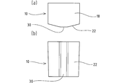
- FIG. 9A is an enlarged side view of the cutting tip 10 of the circular saw blade used in the traveling circular saw cutting machine.
- 9 (b) is a front view showing a rake face located forward in the rotation direction of the cutting tip 10 shown in FIG. 9 (a)
- FIG. 9 (c) is a circular saw blade of the cutting tip 10. It is a top view of the relief surface 18 located in the outer peripheral direction of the above.
- the cutting tip 10 brazed to the outer periphery of the base metal 12 has a first cutting edge 16 at the intersection of the first rake face 14 located in front of the circular saw blade in the rotation direction and the first rake face 14. It is composed of a flank surface 18 forming the above and a second rake face 22 located forward in the rotation direction of the circular saw blade and adjacent to the axial center side of the circular saw blade of the first rake face 14.
- Reference numeral 23 in FIG. 9 indicates a relief groove (nick) that divides cutting chips generated during workpiece cutting.
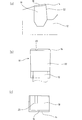
- FIG. 10 is a cross-sectional view showing a situation in which the electric sewing tube 24 is cut by the above-mentioned traveling type circular saw cutting machine.
- the weld bead portion of the electric sewing tube 24 is ground by a grinder. Therefore, as shown in FIG. 10A, the scraped weld bead portion 26 scatters and remains in the pipe. Then, as shown in FIG. 10B, as the circular saw blade rotates, the second rake face 22 of the next cutting tip 10 bites the weld bead portion 26 remaining in the lower part of the pipe with the inner wall of the pipe. It will be crowded.
- the second rake face 22 tends to be excessively worn or chipped.
- the portion a near the joint with the base metal 12 on both sides of the second rake face 22 becomes a stress concentration portion due to engagement with the weld bead portion 26. .. Therefore, this stress concentration portion a becomes the above-mentioned wear or chipped portion.
- a hollow pipe made of tensile strength steel has a high tension (for example , exceeding 1000 N / mm 2 ), so that a conventional circular saw blade eats the pipe with a cutting tip. It may not be attached properly.
- the invention according to claim 1 for solving the above-mentioned problems and achieving the intended object.
- the cutting tip is The first rake face located in front of the circular saw blade in the rotation direction, A first cutting edge is formed at the line of intersection with the first rake surface, and a flank surface located on the outer periphery of the circular saw blade is formed. It is located forward in the direction of rotation of the circular saw blade and consists of a second rake surface adjacent to the axial center side of the circular saw blade of the first rake surface.
- the gist is that the second rake face is configured so that the center thereof protrudes forward in the direction of rotation of the circular saw blade.
- the second rake face of the cutting tip protrudes forward in the direction of rotation of the circular saw, the impact stress when cutting a workpiece such as an electric sewing pipe with a circular saw blade is the first. 2 Spots are concentrated in the center of the rake face, and hardly spread to both sides of the second rake face. Therefore, there is less possibility that the cutting tip is chipped or the tip is chipped from the base metal of the circular saw blade, and as a result, the life of the circular saw blade can be extended.
- the gist of the invention according to claim 2 is that the second rake face forms a second cutting edge at the line of intersection with the flank surface.
- the flank surface and the side surface of the cutting tip and the second cutting edge are increased. The corners of the rake face are less likely to be chipped.
- the center of the second rake face 22 of the cutting tip 10 is projected forward in the rotation direction of the circular saw blade, so that the weld bead portion 26 is bitten during workpiece cutting.
- the stress does not concentrate on both ends of the second rake face 22 even if a large impact is generated. Therefore, it is possible to suppress the possibility that the cutting tip is chipped or the joint portion between the tip 10 and the base metal 12 is damaged or chipped, and the life of the circular saw blade can be extended.
- FIG. 1A is a plan view of a cutting tip according to an embodiment of the present invention
- (b) is a front view showing a second rake face of the tip
- (c) is an overall side view of a circular saw blade. It is an enlarged view of the flank surface of the cutting tip shown in FIG. 1A, and the first rake surface has a triangular shape. It is an enlarged view of the 1st rake face and the 2nd rake face of the cutting tip shown in FIG. 1B, and the 1st rake face in the center shows a triangle.
- the protruding portion of the second rake face is inclined to the left and right with the flat portion in the center.
- (A) is a plan view of the cutting tip according to the second embodiment of the present invention, and (b) is a front view showing a second rake face of the tip.
- (A) is a plan view of the cutting tip according to the third embodiment of the present invention, and (b) is a front view showing a second rake face of the tip.
- (A) is a plan view of the cutting tip according to the fourth embodiment of the present invention, and (b) is a front view showing a second rake face of the tip.
- the first rake face of the polygon formed on the cutting tip according to the embodiment is shown, (a) is the first rake face of a triangle (fan shape), (b) is the first rake face of a quadrangle, and (c) is.
- the pentagonal first rake face and (d) are the hexagonal first rake face.
- (A) is an enlarged side view of a cutting tip in a circular saw blade
- (b) is a front view showing a rake face of the cutting tip
- (c) is a plan view of a flank surface of the cutting tip. It is a cross-sectional view which shows the situation which the electric sewing tube is cut stepwise by the traveling type circular saw cutting machine, (a) shows the situation which the bead part remains in the lower part in a tube, and (b) is for cutting.
- the second rake face of the tip shows a situation in which the bead portion is bitten between the inner wall of the pipe.
- the portions a on both sides of the second rake face are stress concentration portions due to the biting of the bead portion.
- the circular saw blade according to the present invention will be described with reference to the drawings as an example of a cutting tip to be joined to the circular saw blade.
- the cutting target (work) of the circular saw blade according to the embodiment is assumed to be the electric sewing pipe described above, but a work made of a material such as high-strength steel may also be cut.
- FIG. 1 (a) is a plan view of a cutting tip 10 according to an embodiment joined to the outer periphery of the circular saw blade shown in FIG. 1 (c), and FIG. 1 (b) is a second view of the tip 10. It is a front view which shows the rake face 22.
- the second rake face 22 of the cutting tip 10 in the embodiment forms the second cutting edge 52 on both side surfaces at the line of intersection with the flank surface 18.
- a protruding portion 30 is formed in which the center of the second rake face 22 is slightly projected forward in the rotation direction of the circular saw blade. As shown in FIG.
- the protruding portion 30 is formed so as to project from the center of the second rake face 22 in an inclined state to the left and right.
- the left and right lateral rake angles ⁇ shown in FIG. 2 are in the range of 2 ° to 50 °.
- the first rake angle is in the range of ⁇ 30 ° to 0 °, and the second rake angle is in the range of ⁇ 5 ° to 10 °.
- the change in stress applied to the second rake face 22 when the cutting tip comes into contact with the work (welding bead portion) and starts cutting and cuts through the work is the change in the protrusion 30.
- the lateral rake angle ⁇ near the center was 7 ° or more and less than 30 ° for good balance. Comparing the case where the lateral rake angle ⁇ is 0 ° and the case where the lateral rake angle ⁇ is 2 °, the area of the stress concentration portion during work cutting is smaller at 2 °. It was also found that when the lateral rake angle ⁇ exceeds 30 °, a strong stress concentration occurs immediately after the workpiece contacts, so that the risk of chipping increases. However, even when the lateral rake angle ⁇ is 2 ° or 50 °, the effect is sufficiently significant as compared with the conventional cutting tip in which the second rake face 22 is flat.
- the cutting tip 10 of FIG. 1 has a protrusion 30 formed on the second rake face 22 having a linear shape at the intersection of the two faces inclined on both sides. Is formed in.
- the protruding portion 30 may be formed so as to sandwich a flat portion or a round portion instead of being linear between the left and right inclined surfaces. ..
- FIG. 4 is a perspective view of a cutting tip 10 as an embodiment.
- the protruding portion 30 of the second rake face 22 protrudes vertically forward in the rotation direction of the circular saw blade at the center of the second rake face 22. That is, the protruding portion 30 is inclined to the left and right at the center of the second rake face 22 with the flat portion 22a in between.
- the protrusion 30 in FIG. 5 has a rounded round shape, and the protrusion 30 in FIG. 6 is flat. Further, the protrusion 30 in FIG. 7 is flat and chamfered. If the width of the flat surface of the protruding portion 30 in the blade thickness direction exceeds 1 mm, the blade chipping occurs when the weld bead portion 26 is bitten. However, it was found that when the thickness was 1 mm or less, the circular saw blade could cut well even in the presence of the weld bead portion 26.
- the first rake face 14 of the cutting tip 10 has a polygonal shape near the center.
- the first rake face 14 exhibiting this polygon is illustrated in FIGS. 8 (a) to 8 (d). That is, in FIG. 8A, the first rake face 14 has a triangular shape (fan shape), and in FIG. 8B, the first rake face 14 has a quadrangle shape. In FIG. 8C, the first rake face 14 has a pentagonal shape, and in FIG. 8D, the first rake face 14 has a hexagonal shape.
- Cutting insert 12 base metal, 14 1st rake face, 16 1st cutting edge, 18 flank surface, 22 2nd rake surface, ⁇ lateral rake angle, 52 2nd cutting edge
Landscapes
- Engineering & Computer Science (AREA)
- Mechanical Engineering (AREA)
- Sawing (AREA)
Abstract
Description
台金の外周に多数の切削用チップを接合した丸鋸刃において、
前記切削用チップは、
前記丸鋸刃の回転方向前方に位置する第1すくい面と、
前記第1すくい面との交線に第1切れ刃を形成し、前記丸鋸刃の外周に位置する逃げ面と、
前記丸鋸刃の回転方向前方に位置して、第1すくい面の丸鋸刃軸心側に隣接する第2すくい面とからなり、
前記第2すくい面は、その中央を前記丸鋸刃の回転方向前方に突出させるよう構成したことを要旨とする。
請求項1に係る発明によれば、切削用チップの第2すくい面は丸鋸回転方向前方に突出しているから、丸鋸刃で電縫管等のワークを切削する際の衝撃応力は該第2すくい面の中央にスポット的に集中し、第2すくい面の両側へは殆ど波及しない。このため切削用チップが欠損したり、該チップが丸鋸刃の台金から欠落したりする恐れが少なくなり、結果として丸鋸刃の寿命を延ばすことができる。
請求項2に係る発明によれば、切削用チップの両側の第2切れ刃の横すくい角により側面と第2切れ刃との角度が大きくなるため、切削用チップの逃げ面と側面と第2すくい面の角とが欠け難くなる。
Claims (4)
- 台金(12)の外周に多数の切削用チップ(10)を接合した丸鋸刃において、
前記切削用チップ(10)は、
前記丸鋸刃の回転方向前方に位置する第1すくい面(14)と、
前記第1すくい面(14)との交線に第1切れ刃(16)を形成し、前記丸鋸刃の外周に位置する逃げ面(18)と、
前記丸鋸刃の回転方向前方に位置して、第1すくい面(14)の丸鋸刃軸心側に隣接する第2すくい面(22)とからなり、
前記第2すくい面(22)は、その中央を前記丸鋸刃の回転方向前方に突出させるよう構成した
ことを特徴とする丸鋸刃。 - 前記第2すくい面(22)は、前記逃げ面(18)との交線に第2切れ刃(52)を形成している請求項1記載の丸鋸刃。
- 前記第2すくい面(22)は中央から左右に傾斜して突出し、その横すくい角(α)が2°~50°になっている請求項1記載の丸鋸刃。
- 前記逃げ面(18)は前記丸鋸刃の回転軸方向に複数に分割されている請求項1記載の丸鋸刃。
Priority Applications (6)
| Application Number | Priority Date | Filing Date | Title |
|---|---|---|---|
| MX2022010689A MX2022010689A (es) | 2020-02-28 | 2021-02-04 | Hoja de sierra circular. |
| JP2022503211A JPWO2021171945A1 (ja) | 2020-02-28 | 2021-02-04 | |
| CN202180007635.2A CN114901411B (zh) | 2020-02-28 | 2021-02-04 | 圆锯片 |
| US17/760,366 US20230112025A1 (en) | 2020-02-28 | 2021-02-04 | Cicular Saw Blade |
| BR112022016655A BR112022016655A2 (pt) | 2020-02-28 | 2021-02-04 | Lâmina de serra circular |
| EP21761921.2A EP4112213A4 (en) | 2020-02-28 | 2021-02-04 | CIRCULAR SAW BLADE |
Applications Claiming Priority (2)
| Application Number | Priority Date | Filing Date | Title |
|---|---|---|---|
| JP2020-033159 | 2020-02-28 | ||
| JP2020033159 | 2020-02-28 |
Publications (1)
| Publication Number | Publication Date |
|---|---|
| WO2021171945A1 true WO2021171945A1 (ja) | 2021-09-02 |
Family
ID=77490117
Family Applications (1)
| Application Number | Title | Priority Date | Filing Date |
|---|---|---|---|
| PCT/JP2021/004057 WO2021171945A1 (ja) | 2020-02-28 | 2021-02-04 | 丸鋸刃 |
Country Status (7)
| Country | Link |
|---|---|
| US (1) | US20230112025A1 (ja) |
| EP (1) | EP4112213A4 (ja) |
| JP (1) | JPWO2021171945A1 (ja) |
| CN (1) | CN114901411B (ja) |
| BR (1) | BR112022016655A2 (ja) |
| MX (1) | MX2022010689A (ja) |
| WO (1) | WO2021171945A1 (ja) |
Citations (5)
| Publication number | Priority date | Publication date | Assignee | Title |
|---|---|---|---|---|
| JPS63256309A (ja) * | 1987-04-03 | 1988-10-24 | グスタフ ヴァグナー マシーネン ファブ リーク ゲゼルシャフト ミット ベシュレンクテルハフツンク ウント コムパニーコマンディートゲゼルシャフト | 丸鋸の刃部 |
| DE3943321A1 (de) * | 1988-12-29 | 1990-07-05 | Ryobi Ltd | Schneideinsaetze fuer kreissaegeblaetter |
| JPH08224702A (ja) * | 1994-02-23 | 1996-09-03 | Matsushita Electric Works Ltd | 鋸 刃 |
| JP2017042842A (ja) * | 2015-08-24 | 2017-03-02 | 兼房株式会社 | チップ付き丸鋸刃 |
| JP6339764B2 (ja) | 2013-02-25 | 2018-06-06 | 兼房株式会社 | 丸鋸 |
Family Cites Families (5)
| Publication number | Priority date | Publication date | Assignee | Title |
|---|---|---|---|---|
| GB1373084A (en) * | 1970-11-14 | 1974-11-06 | Ellis G A | Cutter teeth pro-provided with carbide tips |
| JPS6028610B2 (ja) * | 1982-07-07 | 1985-07-05 | 兼房刃物工業株式会社 | 金属切断用円鋸 |
| JP2000210816A (ja) * | 1999-01-18 | 2000-08-02 | Masato Kimura | V型チップを使った鋸 |
| WO2013098963A1 (ja) * | 2011-12-27 | 2013-07-04 | 株式会社谷テック | 金属切断用チップソー |
| CN104353898B (zh) * | 2014-09-30 | 2016-08-31 | 杭州和源精密工具有限公司 | 一种切割不锈钢冷锯的制备方法及其锯片 |
-
2021
- 2021-02-04 US US17/760,366 patent/US20230112025A1/en active Pending
- 2021-02-04 WO PCT/JP2021/004057 patent/WO2021171945A1/ja unknown
- 2021-02-04 JP JP2022503211A patent/JPWO2021171945A1/ja active Pending
- 2021-02-04 EP EP21761921.2A patent/EP4112213A4/en active Pending
- 2021-02-04 MX MX2022010689A patent/MX2022010689A/es unknown
- 2021-02-04 BR BR112022016655A patent/BR112022016655A2/pt unknown
- 2021-02-04 CN CN202180007635.2A patent/CN114901411B/zh active Active
Patent Citations (5)
| Publication number | Priority date | Publication date | Assignee | Title |
|---|---|---|---|---|
| JPS63256309A (ja) * | 1987-04-03 | 1988-10-24 | グスタフ ヴァグナー マシーネン ファブ リーク ゲゼルシャフト ミット ベシュレンクテルハフツンク ウント コムパニーコマンディートゲゼルシャフト | 丸鋸の刃部 |
| DE3943321A1 (de) * | 1988-12-29 | 1990-07-05 | Ryobi Ltd | Schneideinsaetze fuer kreissaegeblaetter |
| JPH08224702A (ja) * | 1994-02-23 | 1996-09-03 | Matsushita Electric Works Ltd | 鋸 刃 |
| JP6339764B2 (ja) | 2013-02-25 | 2018-06-06 | 兼房株式会社 | 丸鋸 |
| JP2017042842A (ja) * | 2015-08-24 | 2017-03-02 | 兼房株式会社 | チップ付き丸鋸刃 |
Non-Patent Citations (1)
| Title |
|---|
| See also references of EP4112213A4 |
Also Published As
| Publication number | Publication date |
|---|---|
| CN114901411A (zh) | 2022-08-12 |
| CN114901411B (zh) | 2023-11-07 |
| MX2022010689A (es) | 2022-09-26 |
| EP4112213A1 (en) | 2023-01-04 |
| JPWO2021171945A1 (ja) | 2021-09-02 |
| US20230112025A1 (en) | 2023-04-13 |
| BR112022016655A2 (pt) | 2022-10-11 |
| EP4112213A4 (en) | 2024-03-06 |
Similar Documents
| Publication | Publication Date | Title |
|---|---|---|
| US11413694B2 (en) | Saw blade | |
| EP2777855B1 (en) | Saw blade with chip-limiters | |
| US11813683B2 (en) | Saw blade with set cutting teeth | |
| JP6339764B2 (ja) | 丸鋸 | |
| JP5795892B2 (ja) | 帯鋸刃 | |
| WO2021171945A1 (ja) | 丸鋸刃 | |
| JP3942132B2 (ja) | 溶接継手構造材 | |
| JP2010201565A (ja) | エンドミル | |
| TWI758958B (zh) | 鋼帶的開槽方法、冷軋方法及冷軋鋼帶的製造方法 | |
| CN107921562B (zh) | 附有刀片的圆锯片 | |
| JP2008307621A (ja) | 荒切削用クリスマスカッタ | |
| JP2011101928A (ja) | 鑞付けドリル | |
| KR20220110500A (ko) | 드릴 제조 방법 | |
| JP5249640B2 (ja) | 帯鋸刃 | |
| JP2906136B2 (ja) | 丸 鋸 | |
| JP5607451B2 (ja) | 突切りバイト | |
| CN112958837B (zh) | 一种双金属带锯条及其加工方法 | |
| RU2264893C2 (ru) | Заготовка для пильных полотен или пильных лент | |
| JP4146763B2 (ja) | 金属切断用丸鋸 | |
| JP2006088278A (ja) | リブ溝加工用エンドミル | |
| JP3395658B2 (ja) | 溶接端部のクレータ処理方法 | |
| JPH09225503A (ja) | 金属帯の圧延方法 | |
| JPS62124036A (ja) | 金属棒材端面突き合わせ溶着部のばり取り方法 | |
| UA76448C2 (en) | Billet for preparing of saw blades and method of its production |
Legal Events
| Date | Code | Title | Description |
|---|---|---|---|
| 121 | Ep: the epo has been informed by wipo that ep was designated in this application |
Ref document number: 21761921 Country of ref document: EP Kind code of ref document: A1 |
|
| ENP | Entry into the national phase |
Ref document number: 2022503211 Country of ref document: JP Kind code of ref document: A |
|
| REG | Reference to national code |
Ref country code: BR Ref legal event code: B01A Ref document number: 112022016655 Country of ref document: BR |
|
| NENP | Non-entry into the national phase |
Ref country code: DE |
|
| ENP | Entry into the national phase |
Ref document number: 2021761921 Country of ref document: EP Effective date: 20220928 |
|
| ENP | Entry into the national phase |
Ref document number: 112022016655 Country of ref document: BR Kind code of ref document: A2 Effective date: 20220822 |