WO2021171643A1 - 車載装置、通り抜け判定方法及び記録媒体 - Google Patents
車載装置、通り抜け判定方法及び記録媒体 Download PDFInfo
- Publication number
- WO2021171643A1 WO2021171643A1 PCT/JP2020/026369 JP2020026369W WO2021171643A1 WO 2021171643 A1 WO2021171643 A1 WO 2021171643A1 JP 2020026369 W JP2020026369 W JP 2020026369W WO 2021171643 A1 WO2021171643 A1 WO 2021171643A1
- Authority
- WO
- WIPO (PCT)
- Prior art keywords
- road
- driver
- height
- width
- vehicle
- Prior art date
- Legal status (The legal status is an assumption and is not a legal conclusion. Google has not performed a legal analysis and makes no representation as to the accuracy of the status listed.)
- Ceased
Links
Images


Classifications
-
- G—PHYSICS
- G08—SIGNALLING
- G08G—TRAFFIC CONTROL SYSTEMS
- G08G1/00—Traffic control systems for road vehicles
- G08G1/16—Anti-collision systems
-
- G—PHYSICS
- G08—SIGNALLING
- G08G—TRAFFIC CONTROL SYSTEMS
- G08G1/00—Traffic control systems for road vehicles
- G08G1/01—Detecting movement of traffic to be counted or controlled
- G08G1/0104—Measuring and analyzing of parameters relative to traffic conditions
- G08G1/0125—Traffic data processing
- G08G1/0129—Traffic data processing for creating historical data or processing based on historical data
-
- B—PERFORMING OPERATIONS; TRANSPORTING
- B60—VEHICLES IN GENERAL
- B60W—CONJOINT CONTROL OF VEHICLE SUB-UNITS OF DIFFERENT TYPE OR DIFFERENT FUNCTION; CONTROL SYSTEMS SPECIALLY ADAPTED FOR HYBRID VEHICLES; ROAD VEHICLE DRIVE CONTROL SYSTEMS FOR PURPOSES NOT RELATED TO THE CONTROL OF A PARTICULAR SUB-UNIT
- B60W40/00—Estimation or calculation of non-directly measurable driving parameters for road vehicle drive control systems not related to the control of a particular sub unit, e.g. by using mathematical models
- B60W40/02—Estimation or calculation of non-directly measurable driving parameters for road vehicle drive control systems not related to the control of a particular sub unit, e.g. by using mathematical models related to ambient conditions
- B60W40/04—Traffic conditions
-
- B—PERFORMING OPERATIONS; TRANSPORTING
- B60—VEHICLES IN GENERAL
- B60W—CONJOINT CONTROL OF VEHICLE SUB-UNITS OF DIFFERENT TYPE OR DIFFERENT FUNCTION; CONTROL SYSTEMS SPECIALLY ADAPTED FOR HYBRID VEHICLES; ROAD VEHICLE DRIVE CONTROL SYSTEMS FOR PURPOSES NOT RELATED TO THE CONTROL OF A PARTICULAR SUB-UNIT
- B60W50/00—Details of control systems for road vehicle drive control not related to the control of a particular sub-unit, e.g. process diagnostic or vehicle driver interfaces
- B60W50/08—Interaction between the driver and the control system
- B60W50/14—Means for informing the driver, warning the driver or prompting a driver intervention
-
- G—PHYSICS
- G01—MEASURING; TESTING
- G01C—MEASURING DISTANCES, LEVELS OR BEARINGS; SURVEYING; NAVIGATION; GYROSCOPIC INSTRUMENTS; PHOTOGRAMMETRY OR VIDEOGRAMMETRY
- G01C21/00—Navigation; Navigational instruments not provided for in groups G01C1/00 - G01C19/00
- G01C21/26—Navigation; Navigational instruments not provided for in groups G01C1/00 - G01C19/00 specially adapted for navigation in a road network
- G01C21/34—Route searching; Route guidance
- G01C21/3453—Special cost functions, i.e. other than distance or default speed limit of road segments
- G01C21/3461—Preferred or disfavoured areas, e.g. dangerous zones, toll or emission zones, intersections, manoeuvre types or segments such as motorways, toll roads or ferries
-
- G—PHYSICS
- G01—MEASURING; TESTING
- G01C—MEASURING DISTANCES, LEVELS OR BEARINGS; SURVEYING; NAVIGATION; GYROSCOPIC INSTRUMENTS; PHOTOGRAMMETRY OR VIDEOGRAMMETRY
- G01C21/00—Navigation; Navigational instruments not provided for in groups G01C1/00 - G01C19/00
- G01C21/26—Navigation; Navigational instruments not provided for in groups G01C1/00 - G01C19/00 specially adapted for navigation in a road network
- G01C21/34—Route searching; Route guidance
- G01C21/36—Input/output arrangements for on-board computers
- G01C21/3697—Output of additional, non-guidance related information, e.g. low fuel level
-
- G—PHYSICS
- G01—MEASURING; TESTING
- G01C—MEASURING DISTANCES, LEVELS OR BEARINGS; SURVEYING; NAVIGATION; GYROSCOPIC INSTRUMENTS; PHOTOGRAMMETRY OR VIDEOGRAMMETRY
- G01C21/00—Navigation; Navigational instruments not provided for in groups G01C1/00 - G01C19/00
- G01C21/38—Electronic maps specially adapted for navigation; Updating thereof
- G01C21/3804—Creation or updating of map data
- G01C21/3807—Creation or updating of map data characterised by the type of data
- G01C21/3815—Road data
- G01C21/3822—Road feature data, e.g. slope data
-
- G—PHYSICS
- G06—COMPUTING OR CALCULATING; COUNTING
- G06V—IMAGE OR VIDEO RECOGNITION OR UNDERSTANDING
- G06V20/00—Scenes; Scene-specific elements
- G06V20/50—Context or environment of the image
- G06V20/56—Context or environment of the image exterior to a vehicle by using sensors mounted on the vehicle
- G06V20/588—Recognition of the road, e.g. of lane markings; Recognition of the vehicle driving pattern in relation to the road
-
- G—PHYSICS
- G06—COMPUTING OR CALCULATING; COUNTING
- G06V—IMAGE OR VIDEO RECOGNITION OR UNDERSTANDING
- G06V20/00—Scenes; Scene-specific elements
- G06V20/50—Context or environment of the image
- G06V20/59—Context or environment of the image inside of a vehicle, e.g. relating to seat occupancy, driver state or inner lighting conditions
-
- G—PHYSICS
- G06—COMPUTING OR CALCULATING; COUNTING
- G06V—IMAGE OR VIDEO RECOGNITION OR UNDERSTANDING
- G06V40/00—Recognition of biometric, human-related or animal-related patterns in image or video data
- G06V40/10—Human or animal bodies, e.g. vehicle occupants or pedestrians; Body parts, e.g. hands
- G06V40/12—Fingerprints or palmprints
- G06V40/13—Sensors therefor
-
- G—PHYSICS
- G06—COMPUTING OR CALCULATING; COUNTING
- G06V—IMAGE OR VIDEO RECOGNITION OR UNDERSTANDING
- G06V40/00—Recognition of biometric, human-related or animal-related patterns in image or video data
- G06V40/10—Human or animal bodies, e.g. vehicle occupants or pedestrians; Body parts, e.g. hands
- G06V40/16—Human faces, e.g. facial parts, sketches or expressions
-
- G—PHYSICS
- G08—SIGNALLING
- G08G—TRAFFIC CONTROL SYSTEMS
- G08G1/00—Traffic control systems for road vehicles
- G08G1/01—Detecting movement of traffic to be counted or controlled
- G08G1/0104—Measuring and analyzing of parameters relative to traffic conditions
- G08G1/0125—Traffic data processing
- G08G1/0133—Traffic data processing for classifying traffic situation
-
- G—PHYSICS
- G08—SIGNALLING
- G08G—TRAFFIC CONTROL SYSTEMS
- G08G1/00—Traffic control systems for road vehicles
- G08G1/01—Detecting movement of traffic to be counted or controlled
- G08G1/04—Detecting movement of traffic to be counted or controlled using optical or ultrasonic detectors
-
- B—PERFORMING OPERATIONS; TRANSPORTING
- B60—VEHICLES IN GENERAL
- B60W—CONJOINT CONTROL OF VEHICLE SUB-UNITS OF DIFFERENT TYPE OR DIFFERENT FUNCTION; CONTROL SYSTEMS SPECIALLY ADAPTED FOR HYBRID VEHICLES; ROAD VEHICLE DRIVE CONTROL SYSTEMS FOR PURPOSES NOT RELATED TO THE CONTROL OF A PARTICULAR SUB-UNIT
- B60W2540/00—Input parameters relating to occupants
- B60W2540/043—Identity of occupants
Definitions
- the present disclosure relates to an in-vehicle device, a pass-through determination method, and a recording medium.
- the traveling direction of the own vehicle is imaged, and the road width of the planned road in the traveling direction of the own vehicle is measured (detected) based on the captured image, and the measured road width and passable width (own vehicle)
- a device that compares the value obtained by adding the width and the passage margin) to determine whether or not the vehicle can pass on the planned road, and if it is determined that the vehicle cannot pass, for example, a device that notifies (warns) that fact. It is described in Patent Document 1.
- An object of the present disclosure is to determine for each driver whether or not his / her own vehicle driven by the driver can pass through the planned road, and to notify the determination result.
- An object of the present invention is to provide an in-vehicle device, a pass-through determination method, and a recording medium.
- the in-vehicle device includes a driver identification means for identifying a driver, a planned road width measuring means for measuring a planned road width which is a road width of a planned road, and the driver.
- the passable road width acquisition means for acquiring the passable road width, which is the width of the road that the driver driven by the driver identified by the identification means can pass through, and whether the planned road width is narrower than the passable road width.
- the driver identified by the driver identification means drives the vehicle. It is provided with a notification means for notifying that the own vehicle cannot pass through a narrow road which is a planned travel road determined by the first determination means to have a width of the planned travel road narrower than the width of the road through which the vehicle can pass.
- the in-vehicle device is a driver identifying means for identifying a driver, and traveling for measuring a planned traveling road height which is a height from a road surface of a planned traveling road to an object on the road surface. Acquires the planned road height measuring means and the passable road height which is the height from the road surface of the road driven by the driver identified by the driver identification means to the object on the road surface.
- the own vehicle driven by the driver identified by the driver identification means has the planned road height that is lower than the height of the road that can be passed through by the fifth determination means. It is provided with a notification means for notifying that the road cannot pass through the narrow road which is the determined road to be traveled.
- the pass-through determination method includes a driver identification step for identifying a driver, a planned road width measuring step for measuring a planned road width which is a road width of a planned road, and the operation.
- the passable road width acquisition step for acquiring the passable road width, which is the passable road width for the own vehicle driven by the driver identified by the person identification means, and the planned travel road width are narrower than the passable road width.
- the driver identified by the driver identification means operates.
- the vehicle is provided with a notification step for notifying that the own vehicle cannot pass through a narrow road which is a planned traveling road for which the planned traveling road width is determined to be narrower than the passable road width by the first determination step.
- the pass-through determination method measures the driver identification step for identifying the driver and the planned travel road height, which is the height from the road surface of the planned travel road to an object on the road surface.
- the planned road height measurement step and the passable road height which is the height from the road surface of the road driven by the driver identified by the driver identification means to the object on the road surface.
- the own vehicle driven by the driver identified by the driver identification means has the planned travel height lower than the passable road height by the fifth determination step. It is provided with a notification step for notifying that the vehicle cannot pass through a narrow road which is a planned driving road determined to be.
- the recording medium measures a driver identification process for identifying a driver and a planned road width, which is a road width of the planned road, on an electronic device including at least one processor.
- the driver When the first determination process for determining whether or not the road width is narrower than the passable road width and the first determination process determine that the planned travel width is narrower than the passable road width, the driver The fact that the own vehicle driven by the driver identified by the identification means cannot pass through a narrow road which is a planned travel road whose planned travel width is determined to be narrower than the passable road width by the first determination process. It is a computer-readable recording medium that records a notification process for notifying and a program for executing the notification process.
- the recording medium includes a driver identification process for identifying a driver on an electronic device including at least one processor, and a height from the road surface of the planned road to an object on the road surface.
- the planned road height measurement process for measuring the planned road height, and the road surface to the object on the road surface where the driver's own vehicle identified by the driver identification means can pass through.
- the passable road height acquisition process for acquiring the passable road height, which is the height
- the fifth determination process for determining whether or not the planned road height is lower than the passable road height, and the fifth determination process.
- the own vehicle driven by the driver identified by the driver identification means is the planned travel road by the fifth determination process.
- It is a computer-readable recording medium that records a program for executing a notification process for notifying that a narrow road, which is a planned road to be driven, whose height is determined to be lower than the height of a passable road, cannot be passed. ..
- an in-vehicle device capable of determining whether or not the own vehicle driven by the driver can pass through a planned road and notifying the determination result, a pass-through determination method, and a record.
- a medium can be provided.
- FIG. 7 It is a schematic block diagram of the in-vehicle device 1A. It is a detailed block diagram of the in-vehicle device 1A. This is an example of each data stored in the storage unit 16A. This is an example of the width of the own vehicle V and the like. This is an example of the front image captured by the own vehicle V (front imaging unit 13) at the position P1. This is an example of feature points extracted from the image shown in FIG. This is an example of a front image captured by the own vehicle V (front imaging unit 13) at a position P2 that has advanced ahead of the position P1 shown in FIG. This is an example of feature points extracted from the image shown in FIG. 7.
- FIG. 9 It is a flowchart of an example (pass-through determination process 1) of the operation of the in-vehicle device 1A.
- 9 is a flowchart in which addition width update processing (steps S16 to S23) is added to FIG.
- It is a schematic block diagram of the in-vehicle device 1B. It is a detailed block diagram of the in-vehicle device 1B. This is an example of each data stored in the storage unit 16B.
- FIG. 1 is a schematic configuration diagram of the in-vehicle device 1A. Hereinafter, it is assumed that the in-vehicle device 1A is mounted on the own vehicle V.
- the in-vehicle device 1A includes a driver identification means 21 for identifying a driver, a planned road width measuring means 22 for measuring a planned road width WA, which is the road width of a planned road, and an operation.
- the passable road width WB is acquired.
- the passable road width acquisition means 23 and the planned road width WA can pass through.
- the first determination means 24 for determining whether or not the width is narrower than the width WB and the first determination means 24 determine that the planned road width WA is narrower than the passable road width WB, it is identified by the driver identification means 21.
- the driver for each driver, it is possible to determine whether or not the own vehicle V driven by the driver can pass through the planned travel road, and notify the determination result. As a result, the driver can know in advance that the vehicle V cannot pass through the planned travel road (narrow road).
- FIG. 2 is a detailed configuration diagram of the in-vehicle device 1A. Hereinafter, it is assumed that the in-vehicle device 1A is mounted on the own vehicle V.
- the in-vehicle device 1A mainly has a face image imaging unit 11, a fingerprint sensor 12, a front imaging unit 13, a display unit 14, an input unit 15, and a storage unit 16A as a hardware configuration. And a control unit 17A.
- the face image capturing unit 11 is an imaging device (camera) that captures a face image including the face of the driver who drives the own vehicle V.
- the fingerprint sensor 12 is a sensor that reads the fingerprint of the finger of the driver who drives the vehicle V.
- the front imaging unit 13 is an imaging device (camera) that images the front of the vehicle.
- the front image pickup unit 13 is arranged at a predetermined position in the vehicle interior of the own vehicle V, and captures an image including the planned traveling road in front of the own vehicle V through the front glass of the own vehicle V.
- the planned travel road is a road existing in the traveling direction of the own vehicle V (for example, a road existing a dozen meters to a few tens of meters ahead).
- the display unit 14 is, for example, a liquid crystal display, and is arranged at a predetermined position in the vehicle interior of the own vehicle V so that the driver can easily see it.
- the input unit 15 is arranged on a touch panel, for example, so as to cover the display surface of the display unit 14.
- the storage unit 16A is, for example, a hard disk device.
- FIG. 3 is an example of each data stored in the storage unit 16A.
- FIG. 4 is an example of the vehicle width of the own vehicle V and the like.
- the storage unit 16A As shown in FIG. 3, the storage unit 16A, the vehicle width W V, driver information table TA is stored.
- the storage unit 16A is an example of the vehicle width storage means, the addition width storage means, and the road position information storage means of the present invention.
- the vehicle width W V represents the vehicle width of the vehicle V.
- the vehicle width W V is assumed to be stored in advance in the storage unit 16A.
- the driver information table TA includes "driver information”, “addition width ⁇ ", “total road width W through”, “number of times of passage n”, and “road position information” as items. There is.
- Driver information that identifies the driver is stored in the "driver information".
- the driver information includes, for example, data representing feature points extracted from the driver's face image captured by the face image imaging unit 11, and feature points extracted from the fingerprints of the driver's fingers read by the fingerprint sensor 12. This is data representing the driver's attributes (for example, name, age, gender) input from the input unit 15.
- driver information (driver information 1 and driver information 2) of the two drivers is stored in the "driver information" in advance.
- the driver information may be one person or three or more people.
- the added width to be added to the vehicle width W V of the vehicle V (margin) is stored.
- the driver inputs (sets) a value according to the driving proficiency level and the driving level of the driver via the input unit 15.
- the “addition width ⁇ " is, for example, an arbitrary numerical value between 5 and 100 cm.
- the input addition width is stored in the "addition width ⁇ " of the corresponding driver.
- the input unit 15 is an example of the addition width setting means of the present invention. In the second embodiment, as shown in FIG. 3, it is assumed that the addition widths (addition width ⁇ 1 and addition width ⁇ 2) of the two drivers are stored in the “addition width ⁇ ” in advance.
- the road width of the narrow road determined by the second determination unit 17h described later to have passed through is added to and stored in the "total road width W through".
- the narrow road is a planned traveling road whose planned traveling road width WA (see FIG. 8) is determined to be narrower than the passable road width WB (see FIG. 4) by the first determination unit 17f described later.
- "0" is stored as an initial value in "total road width W through”.
- the road position information indicating the position of the narrow road through which the own vehicle V driven by the driver identified by the driver identification unit 17b has been able to pass in the past is stored.
- the control unit 17A is, for example, an ECU (Electronic Control Unit).
- the control unit 17A includes a processor (not shown).
- the processor is, for example, a CPU. There may be one processor or multiple processors. As shown in FIG. 2, the processor executes a predetermined program read from a non-volatile memory (not shown) such as a ROM into a RAM (not shown) to identify the driver information acquisition unit 17a and the driver.
- Section 17b planned travel width measuring section 17c, passable road width acquisition section 17d, passable road width calculation section 17e, first determination section 17f, notification section 17g, second determination section 17h, addition width update section 17i, pass through It functions as a number counting unit 17j, a third determination unit 17k, and a fourth determination unit 17m. Some or all of these may be implemented in hardware.
- the driver identification unit 17b is an example of the driver identification means 21
- the planned road width measuring unit 17c is an example of the planned road width measuring means 22
- the passable road width acquisition unit 17d is an example of the passable road width acquisition means 23.
- the first determination unit 17f is an example of the first determination means 24, and the notification unit 17g is an example of the notification means 25.
- the driver information acquisition unit 17a reads the driver information of the driver of the own vehicle V, for example, data representing feature points extracted from the driver's face image captured by the face image imaging unit 11, and the fingerprint sensor 12. Data representing the feature points extracted from the fingerprints of the driver's fingers and data representing the attributes (for example, name, age, gender) of the driver input from the input unit 15 are acquired.
- the driver identification unit 17b identifies the driver of the own vehicle V. For example, the driver identification unit 17b compares (verifies) the driver information acquired by the driver information acquisition unit 17a with the "driver information" in the driver information table TA, thereby driving the own vehicle V. Identify the person.
- the planned travel width measuring unit 17c measures the planned travel width WA (see FIG. 8), which is the road width of the planned travel road.
- the planned travel width measuring unit 17c measures the planned travel width WA, which is the road width of the planned travel road, based on the image captured by the front imaging unit 13.
- SLAM Simultaneous Localization and Mapping
- the planned road width measuring unit 17c analyzes the image captured by the front imaging unit 13, extracts the feature points, calculates the distance to the extracted feature points, and determines the coordinates of the feature points. Then, the planned road width WA is calculated based on the determined feature points.
- the distance to each feature point is obtained by triangular parallax survey.
- a triangle is formed at three points: the point before the movement, the point after the movement, and the feature point. The distance to the feature point can be calculated from the length of one side (moving distance) of this triangle and the angles of both corners.
- FIG. 5 is an example of an image in front of the own vehicle captured by the own vehicle V (front imaging unit 13) at position P1. This image includes the planned road R.
- FIG. 6 is an example of feature points extracted from the image shown in FIG. In FIG. 6, each circle represents a feature point.
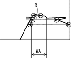
- FIG. 7 is an example of an image in front of the own vehicle captured by the own vehicle V (front imaging unit 13) at the position P2 that has advanced ahead of the position P1 shown in FIG.
- This image includes the planned road R.
- FIG. 8 is an example of feature points extracted from the image shown in FIG. 7. In FIG. 8, each circle represents a feature point.
- the planned travel width measuring unit 17c is scheduled to travel, which is the road width of the planned travel road R based on the extracted feature points (coordinates).
- the road width WA (see FIG. 8) is calculated.
- the passable road width acquisition unit 17d acquires the passable road width WB (see FIG. 4), which is the road width that the own vehicle V driven by the driver identified by the driver identification unit 17b can pass through.
- the passable road width acquisition unit 17d acquires the passable road width WB calculated by the passable road width calculation unit 17e.
- the first determination unit 17f determines whether or not the planned road width WA is narrower than the passable road width WB.
- the notification unit 17g determines that the own vehicle V driven by the driver identified by the driver identification unit 17b is a narrow road. (The first determination unit 17f notifies that the planned driving road width WA cannot pass through the planned driving road determined to be narrower than the passable road width WB). For example, this is displayed on the display unit 14, or voice output (for example, a warning sound is output) from the vehicle-mounted speaker (not shown) of the own vehicle V.
- the second determination unit 17h determines whether or not the own vehicle V driven by the driver identified by the driver identification unit 17b has passed through a narrow road.
- the addition width update unit 17i When the second determination unit 17h determines that the own vehicle V driven by the driver identified by the driver identification unit 17b has passed through a narrow road, the addition width update unit 17i has a storage unit 16A (driver information table). Of the addition width ⁇ stored in TA), the addition width (for example, addition width ⁇ 1) of the driver identified by the driver identification unit 17b is updated.
- the addition width update unit 17i updates, for example, the addition width ⁇ (for example, the addition width ⁇ 1) of the driver identified by the driver identification unit 17b so as to be small.
- the update addition width is calculated by the following formula 1, and of the addition width ⁇ stored in the storage unit 16A (driver information table TA), the addition width of the driver identified by the driver identification unit 17b (for example, The addition width ⁇ 1) is updated (overwritten) with the calculated update addition width.
- Update addition width (((Vehicle width W V + Addition width ⁇ ⁇ 2) + Total road width W through) ⁇ (Number of passages n + 1 ) -Vehicle width W V ) ⁇ 2 ... (Equation 1)
- the pass-through count unit 17j counts the number of times the own vehicle V driven by the driver identified by the driver identification unit 17b has passed through a narrow road. For example, the pass-through count unit 17j determines the pass-through count (for example, pass-through count n1) of the driver identified by the driver identification unit 17b among the pass-through counts n stored in the storage unit 16A (driver information table TA). Count up (eg +1).
- the third determination unit 17k determines whether or not the number of times counted by the pass-through count unit 17j has reached a predetermined number of times.
- the fourth determination unit 17m determines whether or not the own vehicle V driven by the driver identified by the driver identification unit 17b has been able to pass through a narrow road in the past.
- the position of the narrow road which is the planned driving road determined by the first determination unit 17f to be narrower than the road width WB through which the planned driving road width WA can pass, is stored in the storage unit 16A (driver identification unit in the driver information table TA).
- the fourth determination unit 17m the own vehicle V driven by the driver identified by the driver identification unit 17b passes through a narrow road in the past. Judge that it was possible.
- the pass-through determination process 1 will be described as an example of the operation of the in-vehicle device 1A having the above configuration.
- the pass-through determination process 1 is a process for each driver to determine whether or not the own vehicle V driven by the driver can pass through the planned travel road.
- FIG. 9 is a flowchart of an example of the operation of the in-vehicle device 1A (pass-through determination process 1).
- the process of FIG. 9 is realized by the control unit 17A (processor) executing a predetermined program read from the ROM (not shown) or the storage unit 16A into the RAM (not shown).
- the front imaging unit 13 is imaging the front of the own vehicle V at a predetermined frame rate.
- the in-vehicle device 1A acquires the driver information of the driver of the own vehicle V (step S10).
- the driver information of the driver of the own vehicle V data representing the feature points extracted from the driver's face image captured by the face image capturing unit 11 is acquired.
- the in-vehicle device 1A (driver identification unit 17b) identifies the driver of the own vehicle V (step S11).
- driver information 1 FOG. 1
- the in-vehicle device 1A (planned road width measuring unit 17c) is scheduled to travel, which is the road width of the planned traveling road, based on the image (for example, see FIGS. 5 and 7) captured by the front imaging unit 13.
- the road width WA (see, for example, FIG. 8) is measured (step S12).
- the in-vehicle device 1A determines the passable road width WB (see FIG. 4), which is the road width through which the own vehicle V driven by the driver identified in step S11 can pass. Acquire (step S13).
- the passable road width acquisition unit 17d acquires the passable road width WB calculated by the passable road width calculation unit 17e.
- the in-vehicle device 1A determines whether or not the planned travel width WA is narrower than the passable road width WB (step S14).
- step S14 when the in-vehicle device 1A (notifying unit 17g) determines in step S14 that the planned road width WA is narrower than the passable road width WB (step S14: YES), the driver identified in step S11 Notifies that the own vehicle V to be driven cannot pass through the planned road (narrow road) (step S15). For example, this is displayed on the display unit 14, or voice output (for example, a warning sound is output) from the vehicle-mounted speaker (not shown) of the own vehicle V. As a result, the driver is notified that he / she cannot pass through the planned driving road (narrow road).
- voice output for example, a warning sound is output
- FIG. 10 is a flowchart in which addition width update processing (steps S16 to S23) is added to FIG.
- addition width update processing steps S16 to S23
- FIG. 9 the addition width update processing (steps S16 to S23), which is a difference from FIG. 9, will be mainly described.
- the in-vehicle device 1A determines whether or not the own vehicle V driven by the driver identified in step S11 was able to pass through the planned travel road (narrow road) in the past. (Step S16).
- the position of the narrow road which is the planned travel road determined to be narrower than the passable road width WB in step S14, is stored in the storage unit 16A (driving identified in step S11 in the driver information table TA).
- the fourth determination unit 17m determines that the own vehicle V driven by the driver identified by the driver identification unit 17b has been able to pass through the narrow road in the past. ..
- step S16 when it is determined that the own vehicle V driven by the driver identified in step S11 has been able to pass through the narrow road in the past (step S16: YES), the in-vehicle device 1A (notification unit). 17g) notifies that the own vehicle V driven by the driver identified in step S11 has been able to pass through the narrow road in the past (step S17). For example, this is displayed on the display unit 14 or is output as voice from the vehicle-mounted speaker (not shown) of the own vehicle V. This notifies the driver that he / she has passed through a narrow road in the past.
- step S16 when it is determined that the own vehicle V driven by the driver identified in step S11 could not pass through the narrow road in the past (step S16: NO), in step S11. Notifying that the own vehicle V driven by the identified driver cannot pass through the narrow road (step S15).
- the in-vehicle device 1A determines whether or not the own vehicle V driven by the driver identified in step S11 has passed through a narrow road (step S18).
- step S18 when it is determined that the own vehicle V driven by the driver identified in step S11 has passed through the narrow road (step S18: YES), the in-vehicle device 1A (passage count unit 17j) , The number of times the own vehicle V driven by the driver identified in step S11 has passed through the narrow road is counted (step S19).
- the pass-through count unit 17j is the pass-through count n1 of the driver identified by the driver identification unit 17b among the pass-through counts n stored in the storage unit 16A (driver information table TA) (here, the pass-through count n1). Is counted up (for example, +1).
- the total pass-through road width W stored in the storage unit 16A (driver information table TA)
- the total pass-through road width of the driver identified in step S11 (here, the total pass-through road width W1) is added to step S18.
- the road width of the narrow road determined to have passed in is added (step S19).
- the road position information indicating the position of the narrow road determined to be able to pass through in step S18 is the "road position information" of the driver identified in step S11 in the storage unit 16A (driver information table TA). Is stored in (step S20).
- the in-vehicle device 1A determines whether or not the number of passages counted in step S19 has reached a predetermined number (step S21).
- step S21 when it is determined that the number of passages counted in step S19 has reached a predetermined number of times (step S21: YES), the in-vehicle device 1A (notification unit 17g) has an addition width. Inquire the driver about the update (whether or not to update) (step S22). For example, an inquiry to that effect is displayed on the display unit 14 or is output as voice from an in-vehicle speaker (not shown) of the own vehicle V.
- the in-vehicle device 1A updates the addition width (here, addition width ⁇ 1) of the driver identified in step S11 of the addition width ⁇ stored in the storage unit 16A (driver information table TA) (step S24). ..
- the update addition width is calculated by the above formula 1, and of the addition width ⁇ stored in the storage unit 16A (driver information table TA), the addition width of the driver identified in step S11 (here, the addition width ⁇ 1). ) Is updated (overwritten) with the calculated update addition width.
- the passable road width calculation unit 17e calculates the passable road width WB using the updated additional width ⁇ (step S13).
- step S14 it is determined for each driver whether or not the own vehicle V driven by the driver can pass through the planned travel road (step S14), and the determination result is obtained. Can be notified (step S15). As a result, the driver can know in advance that the vehicle V cannot pass through the planned travel road (narrow road).
- step S11 This is when it is determined that the own vehicle V driven by the driver identified in step S11 has passed through the planned travel road (narrow road) (step S18: YES), in the storage unit 16A (driver information table TA). This is because the addition width of the driver identified in step S11 of the stored addition width ⁇ is updated (learned).
- the driver whose road position information representing the position of the narrow road determined to have been able to pass through in step S18 is identified in step S11 in the storage unit 16A (driver information table TA). Since it is stored in the "road position information" (step S20), when passing through the narrow road again, it is possible to notify the driver in advance that the narrow road has been passed in the past. Yes (step S16: YES, step S17).
- step S22, S23 an example of performing a process (steps S22, S23) of inquiring the driver about the update (whether or not to update) the addition width before updating the addition width ⁇ has been described, but the present invention is not limited to this. ..
- the process of asking the driver to update the addition width (whether or not to update) may be omitted.
- Steps S10 to S24 of the second embodiment are not limited to this order.
- step S12 and step S13 may be in the order of step S13 and step S12.
- step S19 and step S20 may be in the order of step S20 and step S19.
- FIG. 11 is a schematic configuration diagram of the in-vehicle device 1B. Hereinafter, it is assumed that the in-vehicle device 1B is mounted on the own vehicle V.
- the in-vehicle device 1B measures the driver identification means 31 for identifying the driver and the planned travel road height HA, which is the height from the road surface of the planned travel road to an object on the road surface.
- Road height that can be passed through which is the height from the road surface of the road on which the own vehicle V driven by the driver identified by the planned traveling road height measuring means 32 and the driver identification means 31 can pass through to an object on the road surface.
- the road travels by the passable road height acquisition means 33 for acquiring the HB, the fifth determination means 34 for determining whether or not the planned road height HA is lower than the passable road height HB, and the fifth determination means 34.
- the own vehicle V driven by the driver identified by the driver identification means 31 is the planned road height traveled by the fifth determination means 34. It is provided with a notification means 35 for notifying that HA cannot pass through a narrow road which is a planned traveling road determined to be lower than the passable road height HB.
- the driver for each driver, it is possible to determine whether or not the own vehicle V driven by the driver can pass through the planned travel road, and notify the determination result. As a result, the driver can know in advance that the vehicle V cannot pass through the planned travel road (narrow road).
- FIG. 12 is a detailed configuration diagram of the in-vehicle device 1B. Hereinafter, it is assumed that the in-vehicle device 1B is mounted on the own vehicle V.
- the in-vehicle device 1B mainly has a face image imaging unit 11, a fingerprint sensor 12, a front imaging unit 13, a display unit 14, an input unit 15, and a storage unit 16B as a hardware configuration. And a control unit 17B. Since the face image imaging unit 11, the fingerprint sensor 12, the front imaging unit 13, the display unit 14, and the input unit 15 have already been described in the second embodiment, the description thereof will be omitted.
- the storage unit 16B is, for example, a hard disk device.
- FIG. 13 is an example of each data stored in the storage unit 16B.
- the storage unit 16B As shown in FIG. 13, the storage unit 16B, the vehicle height H V, driver information table TB is stored.
- the storage unit 16B is an example of the vehicle height storage means, the addition height storage means, and the road position information storage means of the present invention.
- the vehicle height H V represents the vehicle height of the vehicle V.
- the vehicle height H V is assumed to be stored in advance in the storage unit 16B.
- the driver information table TB includes "driver information”, “additional height ⁇ ”, “total road height H”, “number of passages n”, and “road position information” as items. Includes.
- the “addition Height ⁇ ” is added height to be added to the vehicle height H V of the vehicle V (margin) are stored.
- the driver inputs (sets) a value according to the driving proficiency level and the driving level of the driver via the input unit 15.
- the “additional height ⁇ " is, for example, an arbitrary numerical value between 5 and 100 cm.
- the input additional height is stored in the "additional height ⁇ " of the corresponding driver.
- the input unit 15 is an example of the addition height setting means of the present invention.
- the addition heights (addition height ⁇ 1 and addition height ⁇ 2) of the two drivers are preliminarily stored in the “addition height ⁇ ”.
- the road height of the narrow road determined by the fifth determination unit 17Bf described later to have passed through is added to and stored in the "total road height H through".
- the narrow road is a planned traveling road in which the planned traveling road height HA is determined to be lower than the passable road height HB (see FIG. 4) by the fifth determination unit 17Bf described later.
- "0" is stored as an initial value in "total road height H through passing".
- the road position information indicating the position of the narrow road through which the own vehicle V driven by the driver identified by the driver identification unit 17b has been able to pass in the past is stored.
- the control unit 17B is, for example, an ECU (Electronic Control Unit).
- the control unit 17B includes a processor (not shown).
- the processor is, for example, a CPU. There may be one processor or multiple processors. As shown in FIG. 12, the processor executes a predetermined program read from a non-volatile memory (not shown) such as a ROM into a RAM (not shown) to identify the driver information acquisition unit 17a and the driver.
- Section 17b planned travel height measuring section 17Bc, passable road height acquisition section 17Bd, passable road height calculation section 17Be, fifth determination section 17Bf, notification section 17Bg, sixth determination section 17Bh, additional height update It functions as a unit 17Bi, a pass-through count unit 17Bj, a seventh determination unit 17Bk, and an eighth determination unit 17Bm. Some or all of these may be implemented in hardware.
- the driver identification unit 17b is an example of the driver identification means 31
- the planned road height measuring unit 17Bc is an example of the planned road height measuring means 32
- the passable road height acquisition unit 17Bd is a passable road height.
- the fifth determination unit 17Bf is an example of the fifth determination means 34
- the notification unit 17Bg is an example of the notification means 35.
- driver information acquisition unit 17a and the driver identification unit 17b have already been described in the second embodiment, the description thereof will be omitted.
- the planned travel road height measuring unit 17Bc measures the planned travel height HA, which is the height from the road surface of the planned travel road to an object (for example, an elevated) on the road surface.
- the planned travel height measuring unit 17Bc measures the planned travel height HA, which is the height from the road surface of the planned travel road to an object on the road surface, based on the image captured by the front imaging unit 13. do.
- SLAM Simultaneous Localization and Mapping
- the planned road height measuring unit 17Bc analyzes the image captured by the front imaging unit 13, extracts the feature points, calculates the distance to the extracted feature points, and calculates the coordinates of the feature points. It is determined, and the planned road height HA is calculated based on the determined feature points.
- the distance to each feature point is obtained by triangular parallax survey.
- a triangle is formed at three points: the point before the movement, the point after the movement, and the feature point. The distance to the feature point can be calculated from the length of one side (moving distance) of this triangle and the angles of both corners.
- the passable road height acquisition unit 17Bd is the height from the road surface of the road on which the own vehicle V driven by the driver identified by the driver identification unit 17b can pass through to an object on the road surface. HB (see FIG. 4) is acquired.
- the passable road height acquisition unit 17Bd acquires the passable road height HB calculated by the passable road height calculation unit 17Be.
- the fifth determination unit 17Bf determines whether or not the planned road height HA is lower than the passable road height HB.
- the notification unit 17Bg determines that the own vehicle V driven by the driver identified by the driver identification unit 17b Notifies that the vehicle cannot pass through a narrow road (the planned driving road where the planned driving road height HA is determined to be lower than the passable road height HB by the fifth determination unit 17Bf). For example, this is displayed on the display unit 14, or voice output (for example, a warning sound is output) from the vehicle-mounted speaker (not shown) of the own vehicle V.
- the sixth determination unit 17Bh determines whether or not the own vehicle V driven by the driver identified by the driver identification unit 17b has passed through a narrow road.
- the addition height update unit 17Bi stores the storage unit 16B (driver information). Of the addition height ⁇ stored in the table TB), the addition height (for example, addition height ⁇ 1) of the driver identified by the driver identification unit 17b is updated.
- the addition height update unit 17Bi updates, for example, the addition height ⁇ (for example, the addition height ⁇ 1) of the driver identified by the driver identification unit 17b so as to be small.
- the update addition height is calculated by the following equation 2, and of the addition height ⁇ stored in the storage unit 16B (driver information table TB), the addition height of the driver identified by the driver identification unit 17b. (For example, the addition height ⁇ 1) is updated (overwritten) with the calculated update addition height.
- Update adds height ((vehicle height H V + addition height ⁇ ) + through a total road height H) ⁇ through the number of times n + 1- vehicle height H V ⁇ (Equation 2)
- the pass-through count unit 17Bj counts the number of times the own vehicle V driven by the driver identified by the driver identification unit 17b has passed through a narrow road. For example, the pass-through count unit 17Bj determines the number of pass-throughs (for example, pass-through count n1) of the driver identified by the driver identification unit 17b among the pass-through counts n stored in the storage unit 16B (driver information table TB). Count up (eg +1).
- the seventh determination unit 17Bk determines whether or not the number of times counted by the pass-through count unit 17Bj has reached a predetermined number of times.
- the eighth determination unit 17Bm determines whether or not the own vehicle V driven by the driver identified by the driver identification unit 17b has been able to pass through a narrow road in the past.
- the position of the narrow road which is the planned driving road determined by the fifth determination unit 17Bf to be lower than the road height HB through which the planned driving road height HA can pass, is stored in the storage unit 16B (driver in the driver information table TB).
- the eighth determination unit 17Bm the own vehicle V driven by the driver identified by the driver identification unit 17b has past a narrow road. It is judged that it was possible to pass through.
- the pass-through determination process 2 will be described as an example of the operation of the in-vehicle device 1B having the above configuration.
- the pass-through determination process 2 is a process for each driver to determine whether or not the own vehicle V driven by the driver can pass through the planned travel road.
- FIG. 14 is a flowchart of an example of the operation of the in-vehicle device 1B (pass-through determination process 2).
- the process of FIG. 14 is realized by the control unit 17B (processor) executing a predetermined program read from the ROM (not shown) or the storage unit 16B into the RAM (not shown).
- the front imaging unit 13 is imaging the front of the own vehicle V at a predetermined frame rate.
- the in-vehicle device 1B acquires the driver information of the driver of the own vehicle V (step S30).
- the driver information of the driver of the own vehicle V data representing the feature points extracted from the driver's face image captured by the face image capturing unit 11 is acquired.
- the in-vehicle device 1B (driver identification unit 17b) identifies the driver of the own vehicle V (step S31).
- driver information 1 FOG. 1
- the in-vehicle device 1B (planned road height measuring unit 17Bc) is scheduled to travel at a height from the road surface of the planned traveling road to an object on the road surface based on the image captured by the front imaging unit 13.
- the road height HA is measured (step S32).
- the in-vehicle device 1B (passable road height acquisition unit 17Bd) is the height from the road surface of the road through which the own vehicle V driven by the driver identified in step S31 can pass to the object on the road surface. Acquire a certain passable road height HB (see FIG. 4) (step S33).
- the passable road height acquisition unit 17Bd acquires the passable road height HB calculated by the passable road height calculation unit 17Be.
- the in-vehicle device 1B determines whether or not the planned travel height HA is lower than the passable road height HB (step S34).
- step S34 when the in-vehicle device 1B (notifying unit 17Bg) determines in step S34 that the planned road height HA is lower than the passable road height H (step S34: YES), the operation identified in step S31. Notifies that the own vehicle V driven by the person cannot pass through the planned traveling road (narrow road) (step S35). For example, this is displayed on the display unit 14, or voice output (for example, a warning sound is output) from the vehicle-mounted speaker (not shown) of the own vehicle V. As a result, the driver is notified that he / she cannot pass through the planned driving road (narrow road).
- voice output for example, a warning sound is output
- FIG. 15 is a flowchart in which addition height update processing (steps S36 to S44) is added to FIG.
- addition height update processing steps S36 to S44
- FIG. 14 the addition height update processing (steps S36 to S44), which is a difference from FIG. 14, will be mainly described.
- the in-vehicle device 1B (8th determination unit 17Bm) determines whether or not the own vehicle V driven by the driver identified in step S31 was able to pass through the planned travel road (narrow road) in the past. (Step S36).
- the position of the narrow road which is the planned driving road determined in step S34 that the planned driving road height HA is lower than the passable road height HB, is identified in the storage unit 16B (in the driver information table TB, step S31).
- the eighth determination unit 17Bm indicates that the own vehicle V driven by the driver identified by the driver identification unit 17b was able to pass through a narrow road in the past. judge.
- step S36 when it is determined that the own vehicle V driven by the driver identified in step S31 has been able to pass through the narrow road in the past (step S36: YES), the in-vehicle device 1B (notification unit). 17Bg) notifies that the own vehicle V driven by the driver identified in step S31 has been able to pass through the narrow road in the past (step S37). For example, this is displayed on the display unit 14 or is output as voice from the vehicle-mounted speaker (not shown) of the own vehicle V. This notifies the driver that he / she has passed through a narrow road in the past.
- step S36 when it is determined that the own vehicle V driven by the driver identified in step S31 could not pass through the narrow road in the past (step S36: NO), in step S31. Notifying that the own vehicle V driven by the identified driver cannot pass through the narrow road (step S35).
- the in-vehicle device 1B determines whether or not the own vehicle V driven by the driver identified in step S31 has passed through a narrow road (step S38).
- step S38 when it is determined that the own vehicle V driven by the driver identified in step S31 has passed through a narrow road (step S38: YES), the in-vehicle device 1B (passage count unit 17Bj) , The number of times the own vehicle V driven by the driver identified in step S31 has passed through the narrow road is counted (step S39).
- the pass-through count unit 17Bj is the pass-through count n1 of the driver identified by the driver identification unit 17b among the pass-through counts n stored in the storage unit 16B (driver information table TB) (here, the pass-through count n1). Is counted up (for example, +1).
- step S31 the total road height of the driver identified in step S31 (here, the total road height H1 of the pass-through) is calculated.
- the width of the narrow road determined to have passed in step S38 is added (step S39).
- the road position information indicating the position of the narrow road determined to be able to pass through in step S38 is the "road position information" of the driver identified in step S31 in the storage unit 16B (driver information table TB). Is stored in (step S40).
- the in-vehicle device 1B (7th determination unit 17Bk) determines whether or not the number of passages counted in step S39 has reached a predetermined number (step S41).
- step S41 when it is determined that the number of passages counted in step S39 has reached a predetermined number (step S41: YES), the in-vehicle device 1B (notification unit 17Bg) has an additional height. Inquire of the driver about the update (whether or not to update) (step S42). For example, an inquiry to that effect is displayed on the display unit 14 or is output as voice from an in-vehicle speaker (not shown) of the own vehicle V.
- step S43 When updating the addition height in response to the inquiry in step S42 (step S43: YES), for example, when the driver inputs to update the addition height via the input unit 15, the in-vehicle device 1B (addition).
- the height update unit 17Bi) sets the addition height (here, the addition height ⁇ 1) of the driver identified in step S31 among the addition heights ⁇ stored in the storage unit 16B (driver information table TB).
- Update step S44.
- the update addition height is calculated by the above formula 2, and of the addition height ⁇ stored in the storage unit 16B (driver information table TB), the addition height of the driver identified in step S31 (here, the addition height of the driver).
- the addition height ⁇ 1) is updated (overwritten) with the calculated update addition height.
- the passable road height calculation unit 17Be calculates the passable road height HB using the updated added height ⁇ (step S33).
- step S34 it is determined for each driver whether or not the own vehicle V driven by the driver can pass through the planned travel road (step S34), and the determination result is obtained. Can be notified (step S35). As a result, the driver can know in advance that the vehicle V cannot pass through the planned travel road (narrow road).
- addition Height ⁇ is the storage unit 16B (driver information table TB for the operation of the driver ) Is remembered.
- step S38 YES
- step S38 YES
- the road position information indicating the position of the narrow road determined to have been able to pass through in step S38 is the driver identified in step S31 in the storage unit 16B (driver information table TB). Since it is stored in the "road position information" of the above (step S40), when passing through the narrow road again, it is possible to notify the driver in advance that the narrow road has been passed in the past. Yes (step S36: YES, step S37).
- step S42, S43 an example of performing a process (steps S42, S43) of inquiring the driver about the update (whether or not to update) the addition height before updating the addition height ⁇ has been described. Not exclusively.
- the process of inquiring the driver about updating the addition height (whether or not to update) may be omitted.
- Steps S30 to S44 of the fourth embodiment are not limited to this order.
- step S32 and step S33 may be in the order of step S33 and step S32.
- step S39 and step S40 may be in the order of step S40 and step S39.
- the process of the second embodiment for example, the pass-through determination process 1 and the process of the fourth embodiment (for example, the pass-through determination process 2) are executed separately has been described.
- the pass-through determination process 1) and the process of the fourth embodiment for example, the pass-through determination process 2) may be executed in parallel (for example, at the same time as multitasking).
- Non-temporary computer-readable media include various types of tangible storage media.
- Examples of non-temporary computer-readable media include magnetic recording media (eg, flexible disks, magnetic tapes, hard disk drives), magneto-optical recording media (eg, magneto-optical disks), CD-ROMs (Read Only Memory), CD-Rs, Includes CD-R / W and semiconductor memory (for example, mask ROM, PROM (Programmable ROM), EPROM (Erasable PROM), flash ROM, RAM (Random Access Memory)).
- the program may also be supplied to the computer by various types of transient computer readable medium.
- Examples of temporary computer-readable media include electrical, optical, and electromagnetic waves.
- the temporary computer-readable medium can supply the program to the computer via a wired communication path such as an electric wire and an optical fiber, or a wireless communication path.
- Driver identification means to identify the driver and A means for measuring the width of the planned road, which is the width of the planned road, and a means for measuring the width of the planned road.
- the passable road width acquisition means for acquiring the passable road width, which is the passable road width for the own vehicle driven by the driver identified by the driver identification means, and the passable road width acquisition means.
- the first determination means for determining whether or not the road width to be traveled is narrower than the passable road width, and When the first determination means determines that the road width to be traveled is narrower than the passable road width, the own vehicle driven by the driver identified by the driver identification means travels by the first determination means.
- An in-vehicle device including a notification means for notifying that the planned road width cannot pass through a narrow road which is a planned traveling road determined to be narrower than the passable road width.
- Appendix 2 A vehicle width storage means for storing the vehicle width of the own vehicle, An addition width storage means for storing the addition width to be added to the vehicle width of the own vehicle for each driver, and an addition width storage means. Passable road width obtained by adding the vehicle width of the own vehicle stored in the vehicle width storage means and the additional width of the driver identified by the driver identification means among the additional widths stored in the additional width storage means.
- a passable road width calculation means for calculating The vehicle-mounted device according to Appendix 1, wherein the passable road width acquisition means acquires the passable road width calculated by the passable road width calculation means.
- Appendix 3 Further provided with an addition width setting means for setting the addition width, The in-vehicle device according to Appendix 2, wherein the addition width storage means stores the addition width set by the addition width setting means.
- Appendix 4 A second determination means for determining whether or not the own vehicle driven by the driver identified by the driver identification means has passed through the narrow road, and When it is determined by the second determination means that the own vehicle driven by the driver identified by the driver identification means has passed through the narrow road, the driving of the addition width stored in the addition width storage means.
- Appendix 5 The in-vehicle device according to Appendix 4, wherein the addition width updating means updates the addition width of the driver identified by the driver identification means so as to be smaller than that before the update.
- a passing count counting means for counting the number of times the own vehicle driven by the driver identified by the driver identifying means has passed through the narrow road, and a passing count counting means.
- a third determination means for determining whether or not the number of times counted by the pass-through number counting means has reached a predetermined number of times is further provided.
- the addition width updating means is the driver identification means among the addition widths stored in the addition width storage means.
- the in-vehicle device according to Appendix 5, which updates the addition width of the driver identified by.
- the in-vehicle device (Appendix 9) Further equipped with an imaging means to image the front of the vehicle, The in-vehicle device according to any one of Supplementary note 1 to 8, wherein the planned traveling road width measuring means measures the planned traveling road width, which is the road width of the planned traveling road, based on an image captured by the imaging means. .. (Appendix 10)
- Driver identification means to identify the driver and A means for measuring the height of the planned road, which is the height from the road surface of the planned road to an object on the road surface, and a means for measuring the height of the planned road.
- Passable road height acquisition means for acquiring the passable road height, which is the height from the road surface of the road on which the own vehicle driven by the driver identified by the driver identification means can pass through to an object on the road surface.
- a fifth determination means for determining whether or not the height of the planned road is lower than the height of the passable road, and When the fifth determination means determines that the planned road height is lower than the passable road height, the own vehicle driven by the driver identified by the driver identification means is said by the fifth determination means.
- An in-vehicle device including a notification means for notifying that the vehicle cannot pass through a narrow road which is a planned driving road determined that the planned traveling road height is lower than the above-mentioned passable road height.
- Vehicle height storage means to memorize the vehicle height of your own vehicle, For each driver, an additional height storage means for storing the additional height to be added to the vehicle height of the own vehicle, and an additional height storage means.
- a sixth determination means for determining whether or not the own vehicle driven by the driver identified by the driver identification means has passed through the narrow road, and When it is determined by the sixth determination means that the own vehicle driven by the driver identified by the driver identification means has passed through the narrow road, among the addition heights stored in the addition height storage means.
- a passing count counting means for counting the number of times the own vehicle driven by the driver identified by the driver identifying means has passed through the narrow road, and a passing count counting means.
- a seventh determination means for determining whether or not the number of times counted by the pass-through number counting means has reached a predetermined number of times is further provided.
- the addition height updating means is the operation of the addition height stored in the addition height storage means.
- a road position information storage means for storing road position information indicating the position of the narrow road through which the own vehicle driven by the driver identified by the driver identification means has been able to pass in the past.
- the eighth determination means the own vehicle driven by the driver identified by the driver identification means passes through the narrow road in the past.
- the in-vehicle device according to Appendix 16 wherein it is determined that the vehicle has been able to do so.
- the planned travel road height measuring means measures the planned travel road height, which is the height from the road surface of the planned travel road to an object on the road surface, based on the image captured by the imaging means.
- a driver identification step that identifies the driver and The planned road width measurement step that measures the planned road width, which is the road width of the planned road, and The passable road width acquisition step for acquiring the passable road width, which is the passable road width for the own vehicle driven by the driver identified by the driver identification means, and the passable road width acquisition step.
- the first determination step of determining whether or not the road width to be traveled is narrower than the passable road width, and When it is determined by the first determination step that the road width to be traveled is narrower than the passable road width, the own vehicle driven by the driver identified by the driver identification means is driven by the first determination step.
- a pass-through determination method including a notification step for notifying that the planned road width cannot pass through a narrow road which is a planned travel road determined to be narrower than the passable road width.
- a driver identification step that identifies the driver and The planned road height measurement step for measuring the planned road height, which is the height from the road surface of the planned road to the object on the road surface, and A passable road height acquisition step for acquiring a passable road height, which is the height from the road surface of the road on which the own vehicle driven by the driver identified by the driver identification means can pass through to an object on the road surface.
- a fifth determination step for determining whether or not the planned road height is lower than the passable road height, and When it is determined by the fifth determination step that the height of the planned road is lower than the height of the passable road, the own vehicle driven by the driver identified by the driver identification means is said by the fifth determination step.
- a pass-through determination method including a notification step for notifying that the vehicle cannot pass through a narrow road which is a planned travel road determined that the planned travel height is lower than the passable road height.
- (Appendix 21) For electronic devices with at least one processor Driver identification processing to identify the driver and Planned road width measurement processing that measures the planned road width, which is the road width of the planned road, and The passable road width acquisition process for acquiring the passable road width, which is the passable road width for the own vehicle driven by the driver identified by the driver identification means, and the passable road width acquisition process.
- the first determination process for determining whether or not the road width to be traveled is narrower than the passable road width, and When it is determined by the first determination process that the road width to be traveled is narrower than the passable road width, the own vehicle driven by the driver identified by the driver identification means is driven by the first determination process.
- a computer-readable recording medium that records a program for executing a notification process for notifying that a narrow road, which is a planned driving road that is determined to have a planned road width narrower than the passable road width, cannot be passed.
- Appendix 22 For electronic devices with at least one processor Driver identification processing to identify the driver and The planned road height measurement process that measures the planned road height, which is the height from the road surface of the planned road to the object on the road surface, and Passable road height acquisition process for acquiring the passable road height, which is the height from the road surface of the road on which the own vehicle driven by the driver identified by the driver identification means can pass through to an object on the road surface.
- the fifth determination process for determining whether or not the planned road height is lower than the passable road height, and When it is determined by the fifth determination process that the height of the planned road is lower than the height of the passable road, the own vehicle driven by the driver identified by the driver identification means is said by the fifth determination process.
- a computer-readable record that records a program for executing a notification process for notifying that a narrow road, which is a planned driving road determined to be lower than the planned driving road height, cannot be passed. Medium.
Landscapes
- Engineering & Computer Science (AREA)
- Physics & Mathematics (AREA)
- General Physics & Mathematics (AREA)
- Remote Sensing (AREA)
- Radar, Positioning & Navigation (AREA)
- Automation & Control Theory (AREA)
- Multimedia (AREA)
- Theoretical Computer Science (AREA)
- Analytical Chemistry (AREA)
- Chemical & Material Sciences (AREA)
- Human Computer Interaction (AREA)
- Transportation (AREA)
- Mechanical Engineering (AREA)
- Mathematical Physics (AREA)
- Health & Medical Sciences (AREA)
- General Health & Medical Sciences (AREA)
- Oral & Maxillofacial Surgery (AREA)
- Traffic Control Systems (AREA)
Priority Applications (2)
| Application Number | Priority Date | Filing Date | Title |
|---|---|---|---|
| JP2022503067A JP7540482B2 (ja) | 2020-02-28 | 2020-07-06 | 車載装置、通り抜け判定方法及びプログラム |
| US17/800,250 US12112634B2 (en) | 2020-02-28 | 2020-07-06 | In-vehicle device, passing-through determination method, and recording medium |
Applications Claiming Priority (2)
| Application Number | Priority Date | Filing Date | Title |
|---|---|---|---|
| JPPCT/JP2020/008304 | 2020-02-28 | ||
| JP2020008304 | 2020-02-28 |
Publications (1)
| Publication Number | Publication Date |
|---|---|
| WO2021171643A1 true WO2021171643A1 (ja) | 2021-09-02 |
Family
ID=77490826
Family Applications (1)
| Application Number | Title | Priority Date | Filing Date |
|---|---|---|---|
| PCT/JP2020/026369 Ceased WO2021171643A1 (ja) | 2020-02-28 | 2020-07-06 | 車載装置、通り抜け判定方法及び記録媒体 |
Country Status (3)
| Country | Link |
|---|---|
| US (1) | US12112634B2 (https=) |
| JP (1) | JP7540482B2 (https=) |
| WO (1) | WO2021171643A1 (https=) |
Families Citing this family (1)
| Publication number | Priority date | Publication date | Assignee | Title |
|---|---|---|---|---|
| JP7799049B2 (ja) * | 2022-05-13 | 2026-01-14 | 株式会社クボタ | 経路計画システム |
Citations (4)
| Publication number | Priority date | Publication date | Assignee | Title |
|---|---|---|---|---|
| JP2005326963A (ja) * | 2004-05-12 | 2005-11-24 | Fujitsu Ten Ltd | 運転支援装置 |
| JP2007133873A (ja) * | 2005-11-04 | 2007-05-31 | Robert Bosch Gmbh | 狭いところを通過する前および/または通過する際の運転者支援方法および装置 |
| JP2012133614A (ja) * | 2010-12-22 | 2012-07-12 | Nissan Motor Co Ltd | 運転支援表示装置 |
| JP2013043563A (ja) * | 2011-08-24 | 2013-03-04 | Nissan Motor Co Ltd | 走行制御装置 |
Family Cites Families (3)
| Publication number | Priority date | Publication date | Assignee | Title |
|---|---|---|---|---|
| JP4657495B2 (ja) | 2001-05-29 | 2011-03-23 | 富士重工業株式会社 | 車両用運転支援装置 |
| JP2004114907A (ja) * | 2002-09-27 | 2004-04-15 | Fuji Photo Film Co Ltd | 車幅車高検出警告装置 |
| JP6941032B2 (ja) | 2017-11-09 | 2021-09-29 | サカエ理研工業株式会社 | 車両通行判定装置 |
-
2020
- 2020-07-06 US US17/800,250 patent/US12112634B2/en active Active
- 2020-07-06 WO PCT/JP2020/026369 patent/WO2021171643A1/ja not_active Ceased
- 2020-07-06 JP JP2022503067A patent/JP7540482B2/ja active Active
Patent Citations (4)
| Publication number | Priority date | Publication date | Assignee | Title |
|---|---|---|---|---|
| JP2005326963A (ja) * | 2004-05-12 | 2005-11-24 | Fujitsu Ten Ltd | 運転支援装置 |
| JP2007133873A (ja) * | 2005-11-04 | 2007-05-31 | Robert Bosch Gmbh | 狭いところを通過する前および/または通過する際の運転者支援方法および装置 |
| JP2012133614A (ja) * | 2010-12-22 | 2012-07-12 | Nissan Motor Co Ltd | 運転支援表示装置 |
| JP2013043563A (ja) * | 2011-08-24 | 2013-03-04 | Nissan Motor Co Ltd | 走行制御装置 |
Also Published As
| Publication number | Publication date |
|---|---|
| JP7540482B2 (ja) | 2024-08-27 |
| JPWO2021171643A1 (https=) | 2021-09-02 |
| US20230103719A1 (en) | 2023-04-06 |
| US12112634B2 (en) | 2024-10-08 |
Similar Documents
| Publication | Publication Date | Title |
|---|---|---|
| JP6705179B2 (ja) | 交通流量算出方法、装置、及びプログラム | |
| US10198287B2 (en) | System and method for improving motor vehicle safety | |
| DE112015007066T5 (de) | Fahrunterstützungsvorrichtung | |
| JP7243814B2 (ja) | 監視システム、監視装置、監視方法、及びプログラム | |
| JP6214494B2 (ja) | 利用者識別装置、利用者識別方法及びコンピュータプログラム | |
| JPWO2009078056A1 (ja) | 移動物検知装置及び移動物検知プログラム | |
| JP6640146B2 (ja) | 道路区画線診断方法 | |
| WO2021171643A1 (ja) | 車載装置、通り抜け判定方法及び記録媒体 | |
| KR101573243B1 (ko) | 차량 위치 제공 장치, 그리고 그를 이용한 주차 위치 안내 시스템 및 주차 위치 안내 방법 | |
| JP6216624B2 (ja) | 年齢層判定装置および年齢層判定プログラム | |
| KR20170056789A (ko) | 블랙박스 기능을 갖는 avm 시스템 및 운용 방법 | |
| JP2019086889A (ja) | 評価装置、評価システム、車両、およびプログラム | |
| JP2016062157A (ja) | 運転記録装置 | |
| JP6975483B1 (ja) | 物体情報処理装置 | |
| JP2016085105A (ja) | 移動体の速度推定装置、方法、及びプログラム | |
| JP7123665B2 (ja) | 走行制御装置 | |
| JP2017087411A (ja) | 操作ガイダンスシステム、及び、ロボット | |
| CN112364765A (zh) | 一种人眼运动注视点检测方法及装置 | |
| JP2019087824A (ja) | 監視システム | |
| JP6981554B2 (ja) | 識別システム、パラメータ値更新方法およびプログラム | |
| JP6087218B2 (ja) | 画像解析装置 | |
| JP6850740B2 (ja) | 情報出力装置、方法およびプログラム | |
| JP2020181262A (ja) | 客数計測方法及び客数計測装置 | |
| JP5002521B2 (ja) | ナビゲーション装置、ナビゲーション方法およびプログラム | |
| JP7105463B2 (ja) | 情報処理システム、情報処理プログラム、情報処理装置および情報処理方法 |
Legal Events
| Date | Code | Title | Description |
|---|---|---|---|
| 121 | Ep: the epo has been informed by wipo that ep was designated in this application |
Ref document number: 20921148 Country of ref document: EP Kind code of ref document: A1 |
|
| ENP | Entry into the national phase |
Ref document number: 2022503067 Country of ref document: JP Kind code of ref document: A |
|
| NENP | Non-entry into the national phase |
Ref country code: DE |
|
| 122 | Ep: pct application non-entry in european phase |
Ref document number: 20921148 Country of ref document: EP Kind code of ref document: A1 |