WO2021171643A1 - In-vehicle device, passing-through determination method, and recording medium - Google Patents
In-vehicle device, passing-through determination method, and recording medium Download PDFInfo
- Publication number
- WO2021171643A1 WO2021171643A1 PCT/JP2020/026369 JP2020026369W WO2021171643A1 WO 2021171643 A1 WO2021171643 A1 WO 2021171643A1 JP 2020026369 W JP2020026369 W JP 2020026369W WO 2021171643 A1 WO2021171643 A1 WO 2021171643A1
- Authority
- WO
- WIPO (PCT)
- Prior art keywords
- road
- driver
- height
- width
- vehicle
- Prior art date
Links
Images


Classifications
-
- G—PHYSICS
- G08—SIGNALLING
- G08G—TRAFFIC CONTROL SYSTEMS
- G08G1/00—Traffic control systems for road vehicles
- G08G1/16—Anti-collision systems
-
- G—PHYSICS
- G08—SIGNALLING
- G08G—TRAFFIC CONTROL SYSTEMS
- G08G1/00—Traffic control systems for road vehicles
- G08G1/01—Detecting movement of traffic to be counted or controlled
- G08G1/0104—Measuring and analyzing of parameters relative to traffic conditions
- G08G1/0125—Traffic data processing
- G08G1/0129—Traffic data processing for creating historical data or processing based on historical data
-
- B—PERFORMING OPERATIONS; TRANSPORTING
- B60—VEHICLES IN GENERAL
- B60W—CONJOINT CONTROL OF VEHICLE SUB-UNITS OF DIFFERENT TYPE OR DIFFERENT FUNCTION; CONTROL SYSTEMS SPECIALLY ADAPTED FOR HYBRID VEHICLES; ROAD VEHICLE DRIVE CONTROL SYSTEMS FOR PURPOSES NOT RELATED TO THE CONTROL OF A PARTICULAR SUB-UNIT
- B60W40/00—Estimation or calculation of non-directly measurable driving parameters for road vehicle drive control systems not related to the control of a particular sub unit, e.g. by using mathematical models
- B60W40/02—Estimation or calculation of non-directly measurable driving parameters for road vehicle drive control systems not related to the control of a particular sub unit, e.g. by using mathematical models related to ambient conditions
- B60W40/04—Traffic conditions
-
- B—PERFORMING OPERATIONS; TRANSPORTING
- B60—VEHICLES IN GENERAL
- B60W—CONJOINT CONTROL OF VEHICLE SUB-UNITS OF DIFFERENT TYPE OR DIFFERENT FUNCTION; CONTROL SYSTEMS SPECIALLY ADAPTED FOR HYBRID VEHICLES; ROAD VEHICLE DRIVE CONTROL SYSTEMS FOR PURPOSES NOT RELATED TO THE CONTROL OF A PARTICULAR SUB-UNIT
- B60W50/00—Details of control systems for road vehicle drive control not related to the control of a particular sub-unit, e.g. process diagnostic or vehicle driver interfaces
- B60W50/08—Interaction between the driver and the control system
- B60W50/14—Means for informing the driver, warning the driver or prompting a driver intervention
-
- G—PHYSICS
- G01—MEASURING; TESTING
- G01C—MEASURING DISTANCES, LEVELS OR BEARINGS; SURVEYING; NAVIGATION; GYROSCOPIC INSTRUMENTS; PHOTOGRAMMETRY OR VIDEOGRAMMETRY
- G01C21/00—Navigation; Navigational instruments not provided for in groups G01C1/00 - G01C19/00
- G01C21/26—Navigation; Navigational instruments not provided for in groups G01C1/00 - G01C19/00 specially adapted for navigation in a road network
- G01C21/34—Route searching; Route guidance
- G01C21/3453—Special cost functions, i.e. other than distance or default speed limit of road segments
- G01C21/3461—Preferred or disfavoured areas, e.g. dangerous zones, toll or emission zones, intersections, manoeuvre types, segments such as motorways, toll roads, ferries
-
- G—PHYSICS
- G01—MEASURING; TESTING
- G01C—MEASURING DISTANCES, LEVELS OR BEARINGS; SURVEYING; NAVIGATION; GYROSCOPIC INSTRUMENTS; PHOTOGRAMMETRY OR VIDEOGRAMMETRY
- G01C21/00—Navigation; Navigational instruments not provided for in groups G01C1/00 - G01C19/00
- G01C21/26—Navigation; Navigational instruments not provided for in groups G01C1/00 - G01C19/00 specially adapted for navigation in a road network
- G01C21/34—Route searching; Route guidance
- G01C21/36—Input/output arrangements for on-board computers
- G01C21/3697—Output of additional, non-guidance related information, e.g. low fuel level
-
- G—PHYSICS
- G01—MEASURING; TESTING
- G01C—MEASURING DISTANCES, LEVELS OR BEARINGS; SURVEYING; NAVIGATION; GYROSCOPIC INSTRUMENTS; PHOTOGRAMMETRY OR VIDEOGRAMMETRY
- G01C21/00—Navigation; Navigational instruments not provided for in groups G01C1/00 - G01C19/00
- G01C21/38—Electronic maps specially adapted for navigation; Updating thereof
- G01C21/3804—Creation or updating of map data
- G01C21/3807—Creation or updating of map data characterised by the type of data
- G01C21/3815—Road data
- G01C21/3822—Road feature data, e.g. slope data
-
- G—PHYSICS
- G06—COMPUTING; CALCULATING OR COUNTING
- G06V—IMAGE OR VIDEO RECOGNITION OR UNDERSTANDING
- G06V20/00—Scenes; Scene-specific elements
- G06V20/50—Context or environment of the image
- G06V20/56—Context or environment of the image exterior to a vehicle by using sensors mounted on the vehicle
- G06V20/588—Recognition of the road, e.g. of lane markings; Recognition of the vehicle driving pattern in relation to the road
-
- G—PHYSICS
- G06—COMPUTING; CALCULATING OR COUNTING
- G06V—IMAGE OR VIDEO RECOGNITION OR UNDERSTANDING
- G06V20/00—Scenes; Scene-specific elements
- G06V20/50—Context or environment of the image
- G06V20/59—Context or environment of the image inside of a vehicle, e.g. relating to seat occupancy, driver state or inner lighting conditions
-
- G—PHYSICS
- G06—COMPUTING; CALCULATING OR COUNTING
- G06V—IMAGE OR VIDEO RECOGNITION OR UNDERSTANDING
- G06V40/00—Recognition of biometric, human-related or animal-related patterns in image or video data
- G06V40/10—Human or animal bodies, e.g. vehicle occupants or pedestrians; Body parts, e.g. hands
- G06V40/12—Fingerprints or palmprints
- G06V40/13—Sensors therefor
-
- G—PHYSICS
- G06—COMPUTING; CALCULATING OR COUNTING
- G06V—IMAGE OR VIDEO RECOGNITION OR UNDERSTANDING
- G06V40/00—Recognition of biometric, human-related or animal-related patterns in image or video data
- G06V40/10—Human or animal bodies, e.g. vehicle occupants or pedestrians; Body parts, e.g. hands
- G06V40/16—Human faces, e.g. facial parts, sketches or expressions
-
- G—PHYSICS
- G08—SIGNALLING
- G08G—TRAFFIC CONTROL SYSTEMS
- G08G1/00—Traffic control systems for road vehicles
- G08G1/01—Detecting movement of traffic to be counted or controlled
- G08G1/0104—Measuring and analyzing of parameters relative to traffic conditions
- G08G1/0125—Traffic data processing
- G08G1/0133—Traffic data processing for classifying traffic situation
-
- G—PHYSICS
- G08—SIGNALLING
- G08G—TRAFFIC CONTROL SYSTEMS
- G08G1/00—Traffic control systems for road vehicles
- G08G1/01—Detecting movement of traffic to be counted or controlled
- G08G1/04—Detecting movement of traffic to be counted or controlled using optical or ultrasonic detectors
-
- B—PERFORMING OPERATIONS; TRANSPORTING
- B60—VEHICLES IN GENERAL
- B60W—CONJOINT CONTROL OF VEHICLE SUB-UNITS OF DIFFERENT TYPE OR DIFFERENT FUNCTION; CONTROL SYSTEMS SPECIALLY ADAPTED FOR HYBRID VEHICLES; ROAD VEHICLE DRIVE CONTROL SYSTEMS FOR PURPOSES NOT RELATED TO THE CONTROL OF A PARTICULAR SUB-UNIT
- B60W2540/00—Input parameters relating to occupants
- B60W2540/043—Identity of occupants
Definitions
- the present disclosure relates to an in-vehicle device, a pass-through determination method, and a recording medium.
- the traveling direction of the own vehicle is imaged, and the road width of the planned road in the traveling direction of the own vehicle is measured (detected) based on the captured image, and the measured road width and passable width (own vehicle)
- a device that compares the value obtained by adding the width and the passage margin) to determine whether or not the vehicle can pass on the planned road, and if it is determined that the vehicle cannot pass, for example, a device that notifies (warns) that fact. It is described in Patent Document 1.
- An object of the present disclosure is to determine for each driver whether or not his / her own vehicle driven by the driver can pass through the planned road, and to notify the determination result.
- An object of the present invention is to provide an in-vehicle device, a pass-through determination method, and a recording medium.
- the in-vehicle device includes a driver identification means for identifying a driver, a planned road width measuring means for measuring a planned road width which is a road width of a planned road, and the driver.
- the passable road width acquisition means for acquiring the passable road width, which is the width of the road that the driver driven by the driver identified by the identification means can pass through, and whether the planned road width is narrower than the passable road width.
- the driver identified by the driver identification means drives the vehicle. It is provided with a notification means for notifying that the own vehicle cannot pass through a narrow road which is a planned travel road determined by the first determination means to have a width of the planned travel road narrower than the width of the road through which the vehicle can pass.
- the in-vehicle device is a driver identifying means for identifying a driver, and traveling for measuring a planned traveling road height which is a height from a road surface of a planned traveling road to an object on the road surface. Acquires the planned road height measuring means and the passable road height which is the height from the road surface of the road driven by the driver identified by the driver identification means to the object on the road surface.
- the own vehicle driven by the driver identified by the driver identification means has the planned road height that is lower than the height of the road that can be passed through by the fifth determination means. It is provided with a notification means for notifying that the road cannot pass through the narrow road which is the determined road to be traveled.
- the pass-through determination method includes a driver identification step for identifying a driver, a planned road width measuring step for measuring a planned road width which is a road width of a planned road, and the operation.
- the passable road width acquisition step for acquiring the passable road width, which is the passable road width for the own vehicle driven by the driver identified by the person identification means, and the planned travel road width are narrower than the passable road width.
- the driver identified by the driver identification means operates.
- the vehicle is provided with a notification step for notifying that the own vehicle cannot pass through a narrow road which is a planned traveling road for which the planned traveling road width is determined to be narrower than the passable road width by the first determination step.
- the pass-through determination method measures the driver identification step for identifying the driver and the planned travel road height, which is the height from the road surface of the planned travel road to an object on the road surface.
- the planned road height measurement step and the passable road height which is the height from the road surface of the road driven by the driver identified by the driver identification means to the object on the road surface.
- the own vehicle driven by the driver identified by the driver identification means has the planned travel height lower than the passable road height by the fifth determination step. It is provided with a notification step for notifying that the vehicle cannot pass through a narrow road which is a planned driving road determined to be.
- the recording medium measures a driver identification process for identifying a driver and a planned road width, which is a road width of the planned road, on an electronic device including at least one processor.
- the driver When the first determination process for determining whether or not the road width is narrower than the passable road width and the first determination process determine that the planned travel width is narrower than the passable road width, the driver The fact that the own vehicle driven by the driver identified by the identification means cannot pass through a narrow road which is a planned travel road whose planned travel width is determined to be narrower than the passable road width by the first determination process. It is a computer-readable recording medium that records a notification process for notifying and a program for executing the notification process.
- the recording medium includes a driver identification process for identifying a driver on an electronic device including at least one processor, and a height from the road surface of the planned road to an object on the road surface.
- the planned road height measurement process for measuring the planned road height, and the road surface to the object on the road surface where the driver's own vehicle identified by the driver identification means can pass through.
- the passable road height acquisition process for acquiring the passable road height, which is the height
- the fifth determination process for determining whether or not the planned road height is lower than the passable road height, and the fifth determination process.
- the own vehicle driven by the driver identified by the driver identification means is the planned travel road by the fifth determination process.
- It is a computer-readable recording medium that records a program for executing a notification process for notifying that a narrow road, which is a planned road to be driven, whose height is determined to be lower than the height of a passable road, cannot be passed. ..
- an in-vehicle device capable of determining whether or not the own vehicle driven by the driver can pass through a planned road and notifying the determination result, a pass-through determination method, and a record.
- a medium can be provided.
- FIG. 7 It is a schematic block diagram of the in-vehicle device 1A. It is a detailed block diagram of the in-vehicle device 1A. This is an example of each data stored in the storage unit 16A. This is an example of the width of the own vehicle V and the like. This is an example of the front image captured by the own vehicle V (front imaging unit 13) at the position P1. This is an example of feature points extracted from the image shown in FIG. This is an example of a front image captured by the own vehicle V (front imaging unit 13) at a position P2 that has advanced ahead of the position P1 shown in FIG. This is an example of feature points extracted from the image shown in FIG. 7.
- FIG. 9 It is a flowchart of an example (pass-through determination process 1) of the operation of the in-vehicle device 1A.
- 9 is a flowchart in which addition width update processing (steps S16 to S23) is added to FIG.
- It is a schematic block diagram of the in-vehicle device 1B. It is a detailed block diagram of the in-vehicle device 1B. This is an example of each data stored in the storage unit 16B.
- FIG. 1 is a schematic configuration diagram of the in-vehicle device 1A. Hereinafter, it is assumed that the in-vehicle device 1A is mounted on the own vehicle V.
- the in-vehicle device 1A includes a driver identification means 21 for identifying a driver, a planned road width measuring means 22 for measuring a planned road width WA, which is the road width of a planned road, and an operation.
- the passable road width WB is acquired.
- the passable road width acquisition means 23 and the planned road width WA can pass through.
- the first determination means 24 for determining whether or not the width is narrower than the width WB and the first determination means 24 determine that the planned road width WA is narrower than the passable road width WB, it is identified by the driver identification means 21.
- the driver for each driver, it is possible to determine whether or not the own vehicle V driven by the driver can pass through the planned travel road, and notify the determination result. As a result, the driver can know in advance that the vehicle V cannot pass through the planned travel road (narrow road).
- FIG. 2 is a detailed configuration diagram of the in-vehicle device 1A. Hereinafter, it is assumed that the in-vehicle device 1A is mounted on the own vehicle V.
- the in-vehicle device 1A mainly has a face image imaging unit 11, a fingerprint sensor 12, a front imaging unit 13, a display unit 14, an input unit 15, and a storage unit 16A as a hardware configuration. And a control unit 17A.
- the face image capturing unit 11 is an imaging device (camera) that captures a face image including the face of the driver who drives the own vehicle V.
- the fingerprint sensor 12 is a sensor that reads the fingerprint of the finger of the driver who drives the vehicle V.
- the front imaging unit 13 is an imaging device (camera) that images the front of the vehicle.
- the front image pickup unit 13 is arranged at a predetermined position in the vehicle interior of the own vehicle V, and captures an image including the planned traveling road in front of the own vehicle V through the front glass of the own vehicle V.
- the planned travel road is a road existing in the traveling direction of the own vehicle V (for example, a road existing a dozen meters to a few tens of meters ahead).
- the display unit 14 is, for example, a liquid crystal display, and is arranged at a predetermined position in the vehicle interior of the own vehicle V so that the driver can easily see it.
- the input unit 15 is arranged on a touch panel, for example, so as to cover the display surface of the display unit 14.
- the storage unit 16A is, for example, a hard disk device.
- FIG. 3 is an example of each data stored in the storage unit 16A.
- FIG. 4 is an example of the vehicle width of the own vehicle V and the like.
- the storage unit 16A As shown in FIG. 3, the storage unit 16A, the vehicle width W V, driver information table TA is stored.
- the storage unit 16A is an example of the vehicle width storage means, the addition width storage means, and the road position information storage means of the present invention.
- the vehicle width W V represents the vehicle width of the vehicle V.
- the vehicle width W V is assumed to be stored in advance in the storage unit 16A.
- the driver information table TA includes "driver information”, “addition width ⁇ ", “total road width W through”, “number of times of passage n”, and “road position information” as items. There is.
- Driver information that identifies the driver is stored in the "driver information".
- the driver information includes, for example, data representing feature points extracted from the driver's face image captured by the face image imaging unit 11, and feature points extracted from the fingerprints of the driver's fingers read by the fingerprint sensor 12. This is data representing the driver's attributes (for example, name, age, gender) input from the input unit 15.
- driver information (driver information 1 and driver information 2) of the two drivers is stored in the "driver information" in advance.
- the driver information may be one person or three or more people.
- the added width to be added to the vehicle width W V of the vehicle V (margin) is stored.
- the driver inputs (sets) a value according to the driving proficiency level and the driving level of the driver via the input unit 15.
- the “addition width ⁇ " is, for example, an arbitrary numerical value between 5 and 100 cm.
- the input addition width is stored in the "addition width ⁇ " of the corresponding driver.
- the input unit 15 is an example of the addition width setting means of the present invention. In the second embodiment, as shown in FIG. 3, it is assumed that the addition widths (addition width ⁇ 1 and addition width ⁇ 2) of the two drivers are stored in the “addition width ⁇ ” in advance.
- the road width of the narrow road determined by the second determination unit 17h described later to have passed through is added to and stored in the "total road width W through".
- the narrow road is a planned traveling road whose planned traveling road width WA (see FIG. 8) is determined to be narrower than the passable road width WB (see FIG. 4) by the first determination unit 17f described later.
- "0" is stored as an initial value in "total road width W through”.
- the road position information indicating the position of the narrow road through which the own vehicle V driven by the driver identified by the driver identification unit 17b has been able to pass in the past is stored.
- the control unit 17A is, for example, an ECU (Electronic Control Unit).
- the control unit 17A includes a processor (not shown).
- the processor is, for example, a CPU. There may be one processor or multiple processors. As shown in FIG. 2, the processor executes a predetermined program read from a non-volatile memory (not shown) such as a ROM into a RAM (not shown) to identify the driver information acquisition unit 17a and the driver.
- Section 17b planned travel width measuring section 17c, passable road width acquisition section 17d, passable road width calculation section 17e, first determination section 17f, notification section 17g, second determination section 17h, addition width update section 17i, pass through It functions as a number counting unit 17j, a third determination unit 17k, and a fourth determination unit 17m. Some or all of these may be implemented in hardware.
- the driver identification unit 17b is an example of the driver identification means 21
- the planned road width measuring unit 17c is an example of the planned road width measuring means 22
- the passable road width acquisition unit 17d is an example of the passable road width acquisition means 23.
- the first determination unit 17f is an example of the first determination means 24, and the notification unit 17g is an example of the notification means 25.
- the driver information acquisition unit 17a reads the driver information of the driver of the own vehicle V, for example, data representing feature points extracted from the driver's face image captured by the face image imaging unit 11, and the fingerprint sensor 12. Data representing the feature points extracted from the fingerprints of the driver's fingers and data representing the attributes (for example, name, age, gender) of the driver input from the input unit 15 are acquired.
- the driver identification unit 17b identifies the driver of the own vehicle V. For example, the driver identification unit 17b compares (verifies) the driver information acquired by the driver information acquisition unit 17a with the "driver information" in the driver information table TA, thereby driving the own vehicle V. Identify the person.
- the planned travel width measuring unit 17c measures the planned travel width WA (see FIG. 8), which is the road width of the planned travel road.
- the planned travel width measuring unit 17c measures the planned travel width WA, which is the road width of the planned travel road, based on the image captured by the front imaging unit 13.
- SLAM Simultaneous Localization and Mapping
- the planned road width measuring unit 17c analyzes the image captured by the front imaging unit 13, extracts the feature points, calculates the distance to the extracted feature points, and determines the coordinates of the feature points. Then, the planned road width WA is calculated based on the determined feature points.
- the distance to each feature point is obtained by triangular parallax survey.
- a triangle is formed at three points: the point before the movement, the point after the movement, and the feature point. The distance to the feature point can be calculated from the length of one side (moving distance) of this triangle and the angles of both corners.
- FIG. 5 is an example of an image in front of the own vehicle captured by the own vehicle V (front imaging unit 13) at position P1. This image includes the planned road R.
- FIG. 6 is an example of feature points extracted from the image shown in FIG. In FIG. 6, each circle represents a feature point.
- FIG. 7 is an example of an image in front of the own vehicle captured by the own vehicle V (front imaging unit 13) at the position P2 that has advanced ahead of the position P1 shown in FIG.
- This image includes the planned road R.
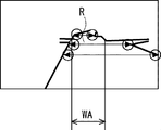
- FIG. 8 is an example of feature points extracted from the image shown in FIG. 7. In FIG. 8, each circle represents a feature point.
- the planned travel width measuring unit 17c is scheduled to travel, which is the road width of the planned travel road R based on the extracted feature points (coordinates).
- the road width WA (see FIG. 8) is calculated.
- the passable road width acquisition unit 17d acquires the passable road width WB (see FIG. 4), which is the road width that the own vehicle V driven by the driver identified by the driver identification unit 17b can pass through.
- the passable road width acquisition unit 17d acquires the passable road width WB calculated by the passable road width calculation unit 17e.
- the first determination unit 17f determines whether or not the planned road width WA is narrower than the passable road width WB.
- the notification unit 17g determines that the own vehicle V driven by the driver identified by the driver identification unit 17b is a narrow road. (The first determination unit 17f notifies that the planned driving road width WA cannot pass through the planned driving road determined to be narrower than the passable road width WB). For example, this is displayed on the display unit 14, or voice output (for example, a warning sound is output) from the vehicle-mounted speaker (not shown) of the own vehicle V.
- the second determination unit 17h determines whether or not the own vehicle V driven by the driver identified by the driver identification unit 17b has passed through a narrow road.
- the addition width update unit 17i When the second determination unit 17h determines that the own vehicle V driven by the driver identified by the driver identification unit 17b has passed through a narrow road, the addition width update unit 17i has a storage unit 16A (driver information table). Of the addition width ⁇ stored in TA), the addition width (for example, addition width ⁇ 1) of the driver identified by the driver identification unit 17b is updated.
- the addition width update unit 17i updates, for example, the addition width ⁇ (for example, the addition width ⁇ 1) of the driver identified by the driver identification unit 17b so as to be small.
- the update addition width is calculated by the following formula 1, and of the addition width ⁇ stored in the storage unit 16A (driver information table TA), the addition width of the driver identified by the driver identification unit 17b (for example, The addition width ⁇ 1) is updated (overwritten) with the calculated update addition width.
- Update addition width (((Vehicle width W V + Addition width ⁇ ⁇ 2) + Total road width W through) ⁇ (Number of passages n + 1 ) -Vehicle width W V ) ⁇ 2 ... (Equation 1)
- the pass-through count unit 17j counts the number of times the own vehicle V driven by the driver identified by the driver identification unit 17b has passed through a narrow road. For example, the pass-through count unit 17j determines the pass-through count (for example, pass-through count n1) of the driver identified by the driver identification unit 17b among the pass-through counts n stored in the storage unit 16A (driver information table TA). Count up (eg +1).
- the third determination unit 17k determines whether or not the number of times counted by the pass-through count unit 17j has reached a predetermined number of times.
- the fourth determination unit 17m determines whether or not the own vehicle V driven by the driver identified by the driver identification unit 17b has been able to pass through a narrow road in the past.
- the position of the narrow road which is the planned driving road determined by the first determination unit 17f to be narrower than the road width WB through which the planned driving road width WA can pass, is stored in the storage unit 16A (driver identification unit in the driver information table TA).
- the fourth determination unit 17m the own vehicle V driven by the driver identified by the driver identification unit 17b passes through a narrow road in the past. Judge that it was possible.
- the pass-through determination process 1 will be described as an example of the operation of the in-vehicle device 1A having the above configuration.
- the pass-through determination process 1 is a process for each driver to determine whether or not the own vehicle V driven by the driver can pass through the planned travel road.
- FIG. 9 is a flowchart of an example of the operation of the in-vehicle device 1A (pass-through determination process 1).
- the process of FIG. 9 is realized by the control unit 17A (processor) executing a predetermined program read from the ROM (not shown) or the storage unit 16A into the RAM (not shown).
- the front imaging unit 13 is imaging the front of the own vehicle V at a predetermined frame rate.
- the in-vehicle device 1A acquires the driver information of the driver of the own vehicle V (step S10).
- the driver information of the driver of the own vehicle V data representing the feature points extracted from the driver's face image captured by the face image capturing unit 11 is acquired.
- the in-vehicle device 1A (driver identification unit 17b) identifies the driver of the own vehicle V (step S11).
- driver information 1 FOG. 1
- the in-vehicle device 1A (planned road width measuring unit 17c) is scheduled to travel, which is the road width of the planned traveling road, based on the image (for example, see FIGS. 5 and 7) captured by the front imaging unit 13.
- the road width WA (see, for example, FIG. 8) is measured (step S12).
- the in-vehicle device 1A determines the passable road width WB (see FIG. 4), which is the road width through which the own vehicle V driven by the driver identified in step S11 can pass. Acquire (step S13).
- the passable road width acquisition unit 17d acquires the passable road width WB calculated by the passable road width calculation unit 17e.
- the in-vehicle device 1A determines whether or not the planned travel width WA is narrower than the passable road width WB (step S14).
- step S14 when the in-vehicle device 1A (notifying unit 17g) determines in step S14 that the planned road width WA is narrower than the passable road width WB (step S14: YES), the driver identified in step S11 Notifies that the own vehicle V to be driven cannot pass through the planned road (narrow road) (step S15). For example, this is displayed on the display unit 14, or voice output (for example, a warning sound is output) from the vehicle-mounted speaker (not shown) of the own vehicle V. As a result, the driver is notified that he / she cannot pass through the planned driving road (narrow road).
- voice output for example, a warning sound is output
- FIG. 10 is a flowchart in which addition width update processing (steps S16 to S23) is added to FIG.
- addition width update processing steps S16 to S23
- FIG. 9 the addition width update processing (steps S16 to S23), which is a difference from FIG. 9, will be mainly described.
- the in-vehicle device 1A determines whether or not the own vehicle V driven by the driver identified in step S11 was able to pass through the planned travel road (narrow road) in the past. (Step S16).
- the position of the narrow road which is the planned travel road determined to be narrower than the passable road width WB in step S14, is stored in the storage unit 16A (driving identified in step S11 in the driver information table TA).
- the fourth determination unit 17m determines that the own vehicle V driven by the driver identified by the driver identification unit 17b has been able to pass through the narrow road in the past. ..
- step S16 when it is determined that the own vehicle V driven by the driver identified in step S11 has been able to pass through the narrow road in the past (step S16: YES), the in-vehicle device 1A (notification unit). 17g) notifies that the own vehicle V driven by the driver identified in step S11 has been able to pass through the narrow road in the past (step S17). For example, this is displayed on the display unit 14 or is output as voice from the vehicle-mounted speaker (not shown) of the own vehicle V. This notifies the driver that he / she has passed through a narrow road in the past.
- step S16 when it is determined that the own vehicle V driven by the driver identified in step S11 could not pass through the narrow road in the past (step S16: NO), in step S11. Notifying that the own vehicle V driven by the identified driver cannot pass through the narrow road (step S15).
- the in-vehicle device 1A determines whether or not the own vehicle V driven by the driver identified in step S11 has passed through a narrow road (step S18).
- step S18 when it is determined that the own vehicle V driven by the driver identified in step S11 has passed through the narrow road (step S18: YES), the in-vehicle device 1A (passage count unit 17j) , The number of times the own vehicle V driven by the driver identified in step S11 has passed through the narrow road is counted (step S19).
- the pass-through count unit 17j is the pass-through count n1 of the driver identified by the driver identification unit 17b among the pass-through counts n stored in the storage unit 16A (driver information table TA) (here, the pass-through count n1). Is counted up (for example, +1).
- the total pass-through road width W stored in the storage unit 16A (driver information table TA)
- the total pass-through road width of the driver identified in step S11 (here, the total pass-through road width W1) is added to step S18.
- the road width of the narrow road determined to have passed in is added (step S19).
- the road position information indicating the position of the narrow road determined to be able to pass through in step S18 is the "road position information" of the driver identified in step S11 in the storage unit 16A (driver information table TA). Is stored in (step S20).
- the in-vehicle device 1A determines whether or not the number of passages counted in step S19 has reached a predetermined number (step S21).
- step S21 when it is determined that the number of passages counted in step S19 has reached a predetermined number of times (step S21: YES), the in-vehicle device 1A (notification unit 17g) has an addition width. Inquire the driver about the update (whether or not to update) (step S22). For example, an inquiry to that effect is displayed on the display unit 14 or is output as voice from an in-vehicle speaker (not shown) of the own vehicle V.
- the in-vehicle device 1A updates the addition width (here, addition width ⁇ 1) of the driver identified in step S11 of the addition width ⁇ stored in the storage unit 16A (driver information table TA) (step S24). ..
- the update addition width is calculated by the above formula 1, and of the addition width ⁇ stored in the storage unit 16A (driver information table TA), the addition width of the driver identified in step S11 (here, the addition width ⁇ 1). ) Is updated (overwritten) with the calculated update addition width.
- the passable road width calculation unit 17e calculates the passable road width WB using the updated additional width ⁇ (step S13).
- step S14 it is determined for each driver whether or not the own vehicle V driven by the driver can pass through the planned travel road (step S14), and the determination result is obtained. Can be notified (step S15). As a result, the driver can know in advance that the vehicle V cannot pass through the planned travel road (narrow road).
- step S11 This is when it is determined that the own vehicle V driven by the driver identified in step S11 has passed through the planned travel road (narrow road) (step S18: YES), in the storage unit 16A (driver information table TA). This is because the addition width of the driver identified in step S11 of the stored addition width ⁇ is updated (learned).
- the driver whose road position information representing the position of the narrow road determined to have been able to pass through in step S18 is identified in step S11 in the storage unit 16A (driver information table TA). Since it is stored in the "road position information" (step S20), when passing through the narrow road again, it is possible to notify the driver in advance that the narrow road has been passed in the past. Yes (step S16: YES, step S17).
- step S22, S23 an example of performing a process (steps S22, S23) of inquiring the driver about the update (whether or not to update) the addition width before updating the addition width ⁇ has been described, but the present invention is not limited to this. ..
- the process of asking the driver to update the addition width (whether or not to update) may be omitted.
- Steps S10 to S24 of the second embodiment are not limited to this order.
- step S12 and step S13 may be in the order of step S13 and step S12.
- step S19 and step S20 may be in the order of step S20 and step S19.
- FIG. 11 is a schematic configuration diagram of the in-vehicle device 1B. Hereinafter, it is assumed that the in-vehicle device 1B is mounted on the own vehicle V.
- the in-vehicle device 1B measures the driver identification means 31 for identifying the driver and the planned travel road height HA, which is the height from the road surface of the planned travel road to an object on the road surface.
- Road height that can be passed through which is the height from the road surface of the road on which the own vehicle V driven by the driver identified by the planned traveling road height measuring means 32 and the driver identification means 31 can pass through to an object on the road surface.
- the road travels by the passable road height acquisition means 33 for acquiring the HB, the fifth determination means 34 for determining whether or not the planned road height HA is lower than the passable road height HB, and the fifth determination means 34.
- the own vehicle V driven by the driver identified by the driver identification means 31 is the planned road height traveled by the fifth determination means 34. It is provided with a notification means 35 for notifying that HA cannot pass through a narrow road which is a planned traveling road determined to be lower than the passable road height HB.
- the driver for each driver, it is possible to determine whether or not the own vehicle V driven by the driver can pass through the planned travel road, and notify the determination result. As a result, the driver can know in advance that the vehicle V cannot pass through the planned travel road (narrow road).
- FIG. 12 is a detailed configuration diagram of the in-vehicle device 1B. Hereinafter, it is assumed that the in-vehicle device 1B is mounted on the own vehicle V.
- the in-vehicle device 1B mainly has a face image imaging unit 11, a fingerprint sensor 12, a front imaging unit 13, a display unit 14, an input unit 15, and a storage unit 16B as a hardware configuration. And a control unit 17B. Since the face image imaging unit 11, the fingerprint sensor 12, the front imaging unit 13, the display unit 14, and the input unit 15 have already been described in the second embodiment, the description thereof will be omitted.
- the storage unit 16B is, for example, a hard disk device.
- FIG. 13 is an example of each data stored in the storage unit 16B.
- the storage unit 16B As shown in FIG. 13, the storage unit 16B, the vehicle height H V, driver information table TB is stored.
- the storage unit 16B is an example of the vehicle height storage means, the addition height storage means, and the road position information storage means of the present invention.
- the vehicle height H V represents the vehicle height of the vehicle V.
- the vehicle height H V is assumed to be stored in advance in the storage unit 16B.
- the driver information table TB includes "driver information”, “additional height ⁇ ”, “total road height H”, “number of passages n”, and “road position information” as items. Includes.
- the “addition Height ⁇ ” is added height to be added to the vehicle height H V of the vehicle V (margin) are stored.
- the driver inputs (sets) a value according to the driving proficiency level and the driving level of the driver via the input unit 15.
- the “additional height ⁇ " is, for example, an arbitrary numerical value between 5 and 100 cm.
- the input additional height is stored in the "additional height ⁇ " of the corresponding driver.
- the input unit 15 is an example of the addition height setting means of the present invention.
- the addition heights (addition height ⁇ 1 and addition height ⁇ 2) of the two drivers are preliminarily stored in the “addition height ⁇ ”.
- the road height of the narrow road determined by the fifth determination unit 17Bf described later to have passed through is added to and stored in the "total road height H through".
- the narrow road is a planned traveling road in which the planned traveling road height HA is determined to be lower than the passable road height HB (see FIG. 4) by the fifth determination unit 17Bf described later.
- "0" is stored as an initial value in "total road height H through passing".
- the road position information indicating the position of the narrow road through which the own vehicle V driven by the driver identified by the driver identification unit 17b has been able to pass in the past is stored.
- the control unit 17B is, for example, an ECU (Electronic Control Unit).
- the control unit 17B includes a processor (not shown).
- the processor is, for example, a CPU. There may be one processor or multiple processors. As shown in FIG. 12, the processor executes a predetermined program read from a non-volatile memory (not shown) such as a ROM into a RAM (not shown) to identify the driver information acquisition unit 17a and the driver.
- Section 17b planned travel height measuring section 17Bc, passable road height acquisition section 17Bd, passable road height calculation section 17Be, fifth determination section 17Bf, notification section 17Bg, sixth determination section 17Bh, additional height update It functions as a unit 17Bi, a pass-through count unit 17Bj, a seventh determination unit 17Bk, and an eighth determination unit 17Bm. Some or all of these may be implemented in hardware.
- the driver identification unit 17b is an example of the driver identification means 31
- the planned road height measuring unit 17Bc is an example of the planned road height measuring means 32
- the passable road height acquisition unit 17Bd is a passable road height.
- the fifth determination unit 17Bf is an example of the fifth determination means 34
- the notification unit 17Bg is an example of the notification means 35.
- driver information acquisition unit 17a and the driver identification unit 17b have already been described in the second embodiment, the description thereof will be omitted.
- the planned travel road height measuring unit 17Bc measures the planned travel height HA, which is the height from the road surface of the planned travel road to an object (for example, an elevated) on the road surface.
- the planned travel height measuring unit 17Bc measures the planned travel height HA, which is the height from the road surface of the planned travel road to an object on the road surface, based on the image captured by the front imaging unit 13. do.
- SLAM Simultaneous Localization and Mapping
- the planned road height measuring unit 17Bc analyzes the image captured by the front imaging unit 13, extracts the feature points, calculates the distance to the extracted feature points, and calculates the coordinates of the feature points. It is determined, and the planned road height HA is calculated based on the determined feature points.
- the distance to each feature point is obtained by triangular parallax survey.
- a triangle is formed at three points: the point before the movement, the point after the movement, and the feature point. The distance to the feature point can be calculated from the length of one side (moving distance) of this triangle and the angles of both corners.
- the passable road height acquisition unit 17Bd is the height from the road surface of the road on which the own vehicle V driven by the driver identified by the driver identification unit 17b can pass through to an object on the road surface. HB (see FIG. 4) is acquired.
- the passable road height acquisition unit 17Bd acquires the passable road height HB calculated by the passable road height calculation unit 17Be.
- the fifth determination unit 17Bf determines whether or not the planned road height HA is lower than the passable road height HB.
- the notification unit 17Bg determines that the own vehicle V driven by the driver identified by the driver identification unit 17b Notifies that the vehicle cannot pass through a narrow road (the planned driving road where the planned driving road height HA is determined to be lower than the passable road height HB by the fifth determination unit 17Bf). For example, this is displayed on the display unit 14, or voice output (for example, a warning sound is output) from the vehicle-mounted speaker (not shown) of the own vehicle V.
- the sixth determination unit 17Bh determines whether or not the own vehicle V driven by the driver identified by the driver identification unit 17b has passed through a narrow road.
- the addition height update unit 17Bi stores the storage unit 16B (driver information). Of the addition height ⁇ stored in the table TB), the addition height (for example, addition height ⁇ 1) of the driver identified by the driver identification unit 17b is updated.
- the addition height update unit 17Bi updates, for example, the addition height ⁇ (for example, the addition height ⁇ 1) of the driver identified by the driver identification unit 17b so as to be small.
- the update addition height is calculated by the following equation 2, and of the addition height ⁇ stored in the storage unit 16B (driver information table TB), the addition height of the driver identified by the driver identification unit 17b. (For example, the addition height ⁇ 1) is updated (overwritten) with the calculated update addition height.
- Update adds height ((vehicle height H V + addition height ⁇ ) + through a total road height H) ⁇ through the number of times n + 1- vehicle height H V ⁇ (Equation 2)
- the pass-through count unit 17Bj counts the number of times the own vehicle V driven by the driver identified by the driver identification unit 17b has passed through a narrow road. For example, the pass-through count unit 17Bj determines the number of pass-throughs (for example, pass-through count n1) of the driver identified by the driver identification unit 17b among the pass-through counts n stored in the storage unit 16B (driver information table TB). Count up (eg +1).
- the seventh determination unit 17Bk determines whether or not the number of times counted by the pass-through count unit 17Bj has reached a predetermined number of times.
- the eighth determination unit 17Bm determines whether or not the own vehicle V driven by the driver identified by the driver identification unit 17b has been able to pass through a narrow road in the past.
- the position of the narrow road which is the planned driving road determined by the fifth determination unit 17Bf to be lower than the road height HB through which the planned driving road height HA can pass, is stored in the storage unit 16B (driver in the driver information table TB).
- the eighth determination unit 17Bm the own vehicle V driven by the driver identified by the driver identification unit 17b has past a narrow road. It is judged that it was possible to pass through.
- the pass-through determination process 2 will be described as an example of the operation of the in-vehicle device 1B having the above configuration.
- the pass-through determination process 2 is a process for each driver to determine whether or not the own vehicle V driven by the driver can pass through the planned travel road.
- FIG. 14 is a flowchart of an example of the operation of the in-vehicle device 1B (pass-through determination process 2).
- the process of FIG. 14 is realized by the control unit 17B (processor) executing a predetermined program read from the ROM (not shown) or the storage unit 16B into the RAM (not shown).
- the front imaging unit 13 is imaging the front of the own vehicle V at a predetermined frame rate.
- the in-vehicle device 1B acquires the driver information of the driver of the own vehicle V (step S30).
- the driver information of the driver of the own vehicle V data representing the feature points extracted from the driver's face image captured by the face image capturing unit 11 is acquired.
- the in-vehicle device 1B (driver identification unit 17b) identifies the driver of the own vehicle V (step S31).
- driver information 1 FOG. 1
- the in-vehicle device 1B (planned road height measuring unit 17Bc) is scheduled to travel at a height from the road surface of the planned traveling road to an object on the road surface based on the image captured by the front imaging unit 13.
- the road height HA is measured (step S32).
- the in-vehicle device 1B (passable road height acquisition unit 17Bd) is the height from the road surface of the road through which the own vehicle V driven by the driver identified in step S31 can pass to the object on the road surface. Acquire a certain passable road height HB (see FIG. 4) (step S33).
- the passable road height acquisition unit 17Bd acquires the passable road height HB calculated by the passable road height calculation unit 17Be.
- the in-vehicle device 1B determines whether or not the planned travel height HA is lower than the passable road height HB (step S34).
- step S34 when the in-vehicle device 1B (notifying unit 17Bg) determines in step S34 that the planned road height HA is lower than the passable road height H (step S34: YES), the operation identified in step S31. Notifies that the own vehicle V driven by the person cannot pass through the planned traveling road (narrow road) (step S35). For example, this is displayed on the display unit 14, or voice output (for example, a warning sound is output) from the vehicle-mounted speaker (not shown) of the own vehicle V. As a result, the driver is notified that he / she cannot pass through the planned driving road (narrow road).
- voice output for example, a warning sound is output
- FIG. 15 is a flowchart in which addition height update processing (steps S36 to S44) is added to FIG.
- addition height update processing steps S36 to S44
- FIG. 14 the addition height update processing (steps S36 to S44), which is a difference from FIG. 14, will be mainly described.
- the in-vehicle device 1B (8th determination unit 17Bm) determines whether or not the own vehicle V driven by the driver identified in step S31 was able to pass through the planned travel road (narrow road) in the past. (Step S36).
- the position of the narrow road which is the planned driving road determined in step S34 that the planned driving road height HA is lower than the passable road height HB, is identified in the storage unit 16B (in the driver information table TB, step S31).
- the eighth determination unit 17Bm indicates that the own vehicle V driven by the driver identified by the driver identification unit 17b was able to pass through a narrow road in the past. judge.
- step S36 when it is determined that the own vehicle V driven by the driver identified in step S31 has been able to pass through the narrow road in the past (step S36: YES), the in-vehicle device 1B (notification unit). 17Bg) notifies that the own vehicle V driven by the driver identified in step S31 has been able to pass through the narrow road in the past (step S37). For example, this is displayed on the display unit 14 or is output as voice from the vehicle-mounted speaker (not shown) of the own vehicle V. This notifies the driver that he / she has passed through a narrow road in the past.
- step S36 when it is determined that the own vehicle V driven by the driver identified in step S31 could not pass through the narrow road in the past (step S36: NO), in step S31. Notifying that the own vehicle V driven by the identified driver cannot pass through the narrow road (step S35).
- the in-vehicle device 1B determines whether or not the own vehicle V driven by the driver identified in step S31 has passed through a narrow road (step S38).
- step S38 when it is determined that the own vehicle V driven by the driver identified in step S31 has passed through a narrow road (step S38: YES), the in-vehicle device 1B (passage count unit 17Bj) , The number of times the own vehicle V driven by the driver identified in step S31 has passed through the narrow road is counted (step S39).
- the pass-through count unit 17Bj is the pass-through count n1 of the driver identified by the driver identification unit 17b among the pass-through counts n stored in the storage unit 16B (driver information table TB) (here, the pass-through count n1). Is counted up (for example, +1).
- step S31 the total road height of the driver identified in step S31 (here, the total road height H1 of the pass-through) is calculated.
- the width of the narrow road determined to have passed in step S38 is added (step S39).
- the road position information indicating the position of the narrow road determined to be able to pass through in step S38 is the "road position information" of the driver identified in step S31 in the storage unit 16B (driver information table TB). Is stored in (step S40).
- the in-vehicle device 1B (7th determination unit 17Bk) determines whether or not the number of passages counted in step S39 has reached a predetermined number (step S41).
- step S41 when it is determined that the number of passages counted in step S39 has reached a predetermined number (step S41: YES), the in-vehicle device 1B (notification unit 17Bg) has an additional height. Inquire of the driver about the update (whether or not to update) (step S42). For example, an inquiry to that effect is displayed on the display unit 14 or is output as voice from an in-vehicle speaker (not shown) of the own vehicle V.
- step S43 When updating the addition height in response to the inquiry in step S42 (step S43: YES), for example, when the driver inputs to update the addition height via the input unit 15, the in-vehicle device 1B (addition).
- the height update unit 17Bi) sets the addition height (here, the addition height ⁇ 1) of the driver identified in step S31 among the addition heights ⁇ stored in the storage unit 16B (driver information table TB).
- Update step S44.
- the update addition height is calculated by the above formula 2, and of the addition height ⁇ stored in the storage unit 16B (driver information table TB), the addition height of the driver identified in step S31 (here, the addition height of the driver).
- the addition height ⁇ 1) is updated (overwritten) with the calculated update addition height.
- the passable road height calculation unit 17Be calculates the passable road height HB using the updated added height ⁇ (step S33).
- step S34 it is determined for each driver whether or not the own vehicle V driven by the driver can pass through the planned travel road (step S34), and the determination result is obtained. Can be notified (step S35). As a result, the driver can know in advance that the vehicle V cannot pass through the planned travel road (narrow road).
- addition Height ⁇ is the storage unit 16B (driver information table TB for the operation of the driver ) Is remembered.
- step S38 YES
- step S38 YES
- the road position information indicating the position of the narrow road determined to have been able to pass through in step S38 is the driver identified in step S31 in the storage unit 16B (driver information table TB). Since it is stored in the "road position information" of the above (step S40), when passing through the narrow road again, it is possible to notify the driver in advance that the narrow road has been passed in the past. Yes (step S36: YES, step S37).
- step S42, S43 an example of performing a process (steps S42, S43) of inquiring the driver about the update (whether or not to update) the addition height before updating the addition height ⁇ has been described. Not exclusively.
- the process of inquiring the driver about updating the addition height (whether or not to update) may be omitted.
- Steps S30 to S44 of the fourth embodiment are not limited to this order.
- step S32 and step S33 may be in the order of step S33 and step S32.
- step S39 and step S40 may be in the order of step S40 and step S39.
- the process of the second embodiment for example, the pass-through determination process 1 and the process of the fourth embodiment (for example, the pass-through determination process 2) are executed separately has been described.
- the pass-through determination process 1) and the process of the fourth embodiment for example, the pass-through determination process 2) may be executed in parallel (for example, at the same time as multitasking).
- Non-temporary computer-readable media include various types of tangible storage media.
- Examples of non-temporary computer-readable media include magnetic recording media (eg, flexible disks, magnetic tapes, hard disk drives), magneto-optical recording media (eg, magneto-optical disks), CD-ROMs (Read Only Memory), CD-Rs, Includes CD-R / W and semiconductor memory (for example, mask ROM, PROM (Programmable ROM), EPROM (Erasable PROM), flash ROM, RAM (Random Access Memory)).
- the program may also be supplied to the computer by various types of transient computer readable medium.
- Examples of temporary computer-readable media include electrical, optical, and electromagnetic waves.
- the temporary computer-readable medium can supply the program to the computer via a wired communication path such as an electric wire and an optical fiber, or a wireless communication path.
- Driver identification means to identify the driver and A means for measuring the width of the planned road, which is the width of the planned road, and a means for measuring the width of the planned road.
- the passable road width acquisition means for acquiring the passable road width, which is the passable road width for the own vehicle driven by the driver identified by the driver identification means, and the passable road width acquisition means.
- the first determination means for determining whether or not the road width to be traveled is narrower than the passable road width, and When the first determination means determines that the road width to be traveled is narrower than the passable road width, the own vehicle driven by the driver identified by the driver identification means travels by the first determination means.
- An in-vehicle device including a notification means for notifying that the planned road width cannot pass through a narrow road which is a planned traveling road determined to be narrower than the passable road width.
- Appendix 2 A vehicle width storage means for storing the vehicle width of the own vehicle, An addition width storage means for storing the addition width to be added to the vehicle width of the own vehicle for each driver, and an addition width storage means. Passable road width obtained by adding the vehicle width of the own vehicle stored in the vehicle width storage means and the additional width of the driver identified by the driver identification means among the additional widths stored in the additional width storage means.
- a passable road width calculation means for calculating The vehicle-mounted device according to Appendix 1, wherein the passable road width acquisition means acquires the passable road width calculated by the passable road width calculation means.
- Appendix 3 Further provided with an addition width setting means for setting the addition width, The in-vehicle device according to Appendix 2, wherein the addition width storage means stores the addition width set by the addition width setting means.
- Appendix 4 A second determination means for determining whether or not the own vehicle driven by the driver identified by the driver identification means has passed through the narrow road, and When it is determined by the second determination means that the own vehicle driven by the driver identified by the driver identification means has passed through the narrow road, the driving of the addition width stored in the addition width storage means.
- Appendix 5 The in-vehicle device according to Appendix 4, wherein the addition width updating means updates the addition width of the driver identified by the driver identification means so as to be smaller than that before the update.
- a passing count counting means for counting the number of times the own vehicle driven by the driver identified by the driver identifying means has passed through the narrow road, and a passing count counting means.
- a third determination means for determining whether or not the number of times counted by the pass-through number counting means has reached a predetermined number of times is further provided.
- the addition width updating means is the driver identification means among the addition widths stored in the addition width storage means.
- the in-vehicle device according to Appendix 5, which updates the addition width of the driver identified by.
- the in-vehicle device (Appendix 9) Further equipped with an imaging means to image the front of the vehicle, The in-vehicle device according to any one of Supplementary note 1 to 8, wherein the planned traveling road width measuring means measures the planned traveling road width, which is the road width of the planned traveling road, based on an image captured by the imaging means. .. (Appendix 10)
- Driver identification means to identify the driver and A means for measuring the height of the planned road, which is the height from the road surface of the planned road to an object on the road surface, and a means for measuring the height of the planned road.
- Passable road height acquisition means for acquiring the passable road height, which is the height from the road surface of the road on which the own vehicle driven by the driver identified by the driver identification means can pass through to an object on the road surface.
- a fifth determination means for determining whether or not the height of the planned road is lower than the height of the passable road, and When the fifth determination means determines that the planned road height is lower than the passable road height, the own vehicle driven by the driver identified by the driver identification means is said by the fifth determination means.
- An in-vehicle device including a notification means for notifying that the vehicle cannot pass through a narrow road which is a planned driving road determined that the planned traveling road height is lower than the above-mentioned passable road height.
- Vehicle height storage means to memorize the vehicle height of your own vehicle, For each driver, an additional height storage means for storing the additional height to be added to the vehicle height of the own vehicle, and an additional height storage means.
- a sixth determination means for determining whether or not the own vehicle driven by the driver identified by the driver identification means has passed through the narrow road, and When it is determined by the sixth determination means that the own vehicle driven by the driver identified by the driver identification means has passed through the narrow road, among the addition heights stored in the addition height storage means.
- a passing count counting means for counting the number of times the own vehicle driven by the driver identified by the driver identifying means has passed through the narrow road, and a passing count counting means.
- a seventh determination means for determining whether or not the number of times counted by the pass-through number counting means has reached a predetermined number of times is further provided.
- the addition height updating means is the operation of the addition height stored in the addition height storage means.
- a road position information storage means for storing road position information indicating the position of the narrow road through which the own vehicle driven by the driver identified by the driver identification means has been able to pass in the past.
- the eighth determination means the own vehicle driven by the driver identified by the driver identification means passes through the narrow road in the past.
- the in-vehicle device according to Appendix 16 wherein it is determined that the vehicle has been able to do so.
- the planned travel road height measuring means measures the planned travel road height, which is the height from the road surface of the planned travel road to an object on the road surface, based on the image captured by the imaging means.
- a driver identification step that identifies the driver and The planned road width measurement step that measures the planned road width, which is the road width of the planned road, and The passable road width acquisition step for acquiring the passable road width, which is the passable road width for the own vehicle driven by the driver identified by the driver identification means, and the passable road width acquisition step.
- the first determination step of determining whether or not the road width to be traveled is narrower than the passable road width, and When it is determined by the first determination step that the road width to be traveled is narrower than the passable road width, the own vehicle driven by the driver identified by the driver identification means is driven by the first determination step.
- a pass-through determination method including a notification step for notifying that the planned road width cannot pass through a narrow road which is a planned travel road determined to be narrower than the passable road width.
- a driver identification step that identifies the driver and The planned road height measurement step for measuring the planned road height, which is the height from the road surface of the planned road to the object on the road surface, and A passable road height acquisition step for acquiring a passable road height, which is the height from the road surface of the road on which the own vehicle driven by the driver identified by the driver identification means can pass through to an object on the road surface.
- a fifth determination step for determining whether or not the planned road height is lower than the passable road height, and When it is determined by the fifth determination step that the height of the planned road is lower than the height of the passable road, the own vehicle driven by the driver identified by the driver identification means is said by the fifth determination step.
- a pass-through determination method including a notification step for notifying that the vehicle cannot pass through a narrow road which is a planned travel road determined that the planned travel height is lower than the passable road height.
- (Appendix 21) For electronic devices with at least one processor Driver identification processing to identify the driver and Planned road width measurement processing that measures the planned road width, which is the road width of the planned road, and The passable road width acquisition process for acquiring the passable road width, which is the passable road width for the own vehicle driven by the driver identified by the driver identification means, and the passable road width acquisition process.
- the first determination process for determining whether or not the road width to be traveled is narrower than the passable road width, and When it is determined by the first determination process that the road width to be traveled is narrower than the passable road width, the own vehicle driven by the driver identified by the driver identification means is driven by the first determination process.
- a computer-readable recording medium that records a program for executing a notification process for notifying that a narrow road, which is a planned driving road that is determined to have a planned road width narrower than the passable road width, cannot be passed.
- Appendix 22 For electronic devices with at least one processor Driver identification processing to identify the driver and The planned road height measurement process that measures the planned road height, which is the height from the road surface of the planned road to the object on the road surface, and Passable road height acquisition process for acquiring the passable road height, which is the height from the road surface of the road on which the own vehicle driven by the driver identified by the driver identification means can pass through to an object on the road surface.
- the fifth determination process for determining whether or not the planned road height is lower than the passable road height, and When it is determined by the fifth determination process that the height of the planned road is lower than the height of the passable road, the own vehicle driven by the driver identified by the driver identification means is said by the fifth determination process.
- a computer-readable record that records a program for executing a notification process for notifying that a narrow road, which is a planned driving road determined to be lower than the planned driving road height, cannot be passed. Medium.
Landscapes
- Engineering & Computer Science (AREA)
- Physics & Mathematics (AREA)
- General Physics & Mathematics (AREA)
- Remote Sensing (AREA)
- Radar, Positioning & Navigation (AREA)
- Automation & Control Theory (AREA)
- Multimedia (AREA)
- Theoretical Computer Science (AREA)
- Analytical Chemistry (AREA)
- Chemical & Material Sciences (AREA)
- Human Computer Interaction (AREA)
- Transportation (AREA)
- Mechanical Engineering (AREA)
- Mathematical Physics (AREA)
- Health & Medical Sciences (AREA)
- General Health & Medical Sciences (AREA)
- Oral & Maxillofacial Surgery (AREA)
- Traffic Control Systems (AREA)
Abstract
An in-vehicle device (1A) of the present disclosure comprises: a driver identification means (21) for identifying a driver; a traveling-scheduled road width measurement means (22) for measuring a traveling-scheduled road width that is the road width of a traveling-scheduled road; a passable road width acquisition mean (23) for acquiring a passable road width with which an own vehicle driven by the driver identified by the driver identification means (21) can pass through the road; a first determination means (24) for determining whether or not the width of a road scheduled for travel is smaller than the passable road width; and a notification means (25) for, when the first determination means (24) determines that the width of the road scheduled for travel is smaller than the passable road width, providing a notification that the own vehicle driven by the driver identified by the driver identification means (21) cannot pass through a narrow road that is the road scheduled for travel determined by the first determination means (24) to be narrower than the passable road width.
Description
本開示は、車載装置、通り抜け判定方法及び記録媒体に関する。
The present disclosure relates to an in-vehicle device, a pass-through determination method, and a recording medium.
自車の進行方向を撮像し、この撮像した画像に基づいて自車の進行方向の走行予定道路の道路幅を測定(検出)し、この測定された道路幅と通行可能幅(自車の車幅と通過余裕とを加算した値)とを比較して自車が走行予定道路を通行できるか否かを判定し、通行できないと判定された場合、その旨を報知(警告)する装置が例えば特許文献1に記載されている。
The traveling direction of the own vehicle is imaged, and the road width of the planned road in the traveling direction of the own vehicle is measured (detected) based on the captured image, and the measured road width and passable width (own vehicle) A device that compares (the value obtained by adding the width and the passage margin) to determine whether or not the vehicle can pass on the planned road, and if it is determined that the vehicle cannot pass, for example, a device that notifies (warns) that fact. It is described in Patent Document 1.
しかしながら、特許文献1に記載の装置においては、運転者ごとに、当該運転者が運転する自車が走行予定道路を通り抜けることができるか否かを判定し、その判定結果を報知することについては全く提案されていない。
However, in the device described in Patent Document 1, for each driver, it is determined whether or not the own vehicle driven by the driver can pass through the planned traveling road, and the determination result is notified. Not proposed at all.
本開示の目的は、上述した課題を鑑み、運転者ごとに、当該運転者が運転する自車が走行予定道路を通り抜けることができるか否かを判定し、その判定結果を報知することができる車載装置、通り抜け判定方法及び記録媒体を提供することにある。
An object of the present disclosure is to determine for each driver whether or not his / her own vehicle driven by the driver can pass through the planned road, and to notify the determination result. An object of the present invention is to provide an in-vehicle device, a pass-through determination method, and a recording medium.
本開示の第1の態様にかかる車載装置は、運転者を識別する運転者識別手段と、走行予定道路の道路幅である走行予定道路幅を測定する走行予定道路幅測定手段と、前記運転者識別手段により識別された運転者が運転する自車が通り抜け可能な道路幅である通り抜け可能道路幅を取得する通り抜け可能道路幅取得手段と、前記走行予定道路幅が前記通り抜け可能道路幅より狭いか否かを判定する第1判定手段と、前記第1判定手段により前記走行予定道路幅が前記通り抜け可能道路幅より狭いと判定された場合、前記運転者識別手段により識別された運転者が運転する自車が前記第1判定手段により前記走行予定道路幅が前記通り抜け可能道路幅より狭いと判定された走行予定道路である狭路を通り抜けられない旨を報知する報知手段と、を備える。
The in-vehicle device according to the first aspect of the present disclosure includes a driver identification means for identifying a driver, a planned road width measuring means for measuring a planned road width which is a road width of a planned road, and the driver. The passable road width acquisition means for acquiring the passable road width, which is the width of the road that the driver driven by the driver identified by the identification means can pass through, and whether the planned road width is narrower than the passable road width. When it is determined by the first determination means for determining whether or not the road is narrower than the width of the road that can be passed through, the driver identified by the driver identification means drives the vehicle. It is provided with a notification means for notifying that the own vehicle cannot pass through a narrow road which is a planned travel road determined by the first determination means to have a width of the planned travel road narrower than the width of the road through which the vehicle can pass.
本開示の第2の態様にかかる車載装置は、運転者を識別する運転者識別手段と、走行予定道路の路面から当該路面上の物体までの高さである走行予定道路高さを測定する走行予定道路高さ測定手段と、前記運転者識別手段により識別された運転者が運転する自車が通り抜け可能な道路の路面から当該路面上の物体までの高さである通り抜け可能道路高さを取得する通り抜け可能道路高さ取得手段と、前記走行予定道路高さが前記通り抜け可能道路高さより低いか否かを判定する第5判定手段と、前記第5判定手段により前記走行予定道路高さが前記通り抜け可能道路高さより低いと判定された場合、前記運転者識別手段により識別された運転者が運転する自車が前記第5判定手段により前記走行予定道路高さが前記通り抜け可能道路高さより低いと判定された走行予定道路である狭路を通り抜けられない旨を報知する報知手段と、を備える。
The in-vehicle device according to the second aspect of the present disclosure is a driver identifying means for identifying a driver, and traveling for measuring a planned traveling road height which is a height from a road surface of a planned traveling road to an object on the road surface. Acquires the planned road height measuring means and the passable road height which is the height from the road surface of the road driven by the driver identified by the driver identification means to the object on the road surface. The road height acquisition means for passing through, the fifth determination means for determining whether or not the height of the planned road to be traveled is lower than the height of the road that can be passed through, and the fifth determination means for determining the height of the planned travel road. When it is determined that the height of the road that can be passed through is lower than the height of the road that can be passed through, it is determined that the own vehicle driven by the driver identified by the driver identification means has the planned road height that is lower than the height of the road that can be passed through by the fifth determination means. It is provided with a notification means for notifying that the road cannot pass through the narrow road which is the determined road to be traveled.
本開示の第3の態様にかかる通り抜け判定方法は、運転者を識別する運転者識別ステップと、走行予定道路の道路幅である走行予定道路幅を測定する走行予定道路幅測定ステップと、前記運転者識別手段により識別された運転者が運転する自車が通り抜け可能な道路幅である通り抜け可能道路幅を取得する通り抜け可能道路幅取得ステップと、前記走行予定道路幅が前記通り抜け可能道路幅より狭いか否かを判定する第1判定ステップと、前記第1判定ステップにより前記走行予定道路幅が前記通り抜け可能道路幅より狭いと判定された場合、前記運転者識別手段により識別された運転者が運転する自車が前記第1判定ステップにより前記走行予定道路幅が前記通り抜け可能道路幅より狭いと判定された走行予定道路である狭路を通り抜けられない旨を報知する報知ステップと、を備える。
The pass-through determination method according to the third aspect of the present disclosure includes a driver identification step for identifying a driver, a planned road width measuring step for measuring a planned road width which is a road width of a planned road, and the operation. The passable road width acquisition step for acquiring the passable road width, which is the passable road width for the own vehicle driven by the driver identified by the person identification means, and the planned travel road width are narrower than the passable road width. When it is determined by the first determination step for determining whether or not the road is narrower than the passable road width by the first determination step, the driver identified by the driver identification means operates. The vehicle is provided with a notification step for notifying that the own vehicle cannot pass through a narrow road which is a planned traveling road for which the planned traveling road width is determined to be narrower than the passable road width by the first determination step.
本開示の第4の態様にかかる通り抜け判定方法は、運転者を識別する運転者識別ステップと、走行予定道路の路面から当該路面上の物体までの高さである走行予定道路高さを測定する走行予定道路高さ測定ステップと、前記運転者識別手段により識別された運転者が運転する自車が通り抜け可能な道路の路面から当該路面上の物体までの高さである通り抜け可能道路高さを取得する通り抜け可能道路高さ取得ステップと、前記走行予定道路高さが前記通り抜け可能道路高さより低いか否かを判定する第5判定ステップと、前記第5判定ステップにより前記走行予定道路高さが前記通り抜け可能道路高さより低いと判定された場合、前記運転者識別手段により識別された運転者が運転する自車が前記第5判定ステップにより前記走行予定道路高さが前記通り抜け可能道路高さより低いと判定された走行予定道路である狭路を通り抜けられない旨を報知する報知ステップと、を備える。
The pass-through determination method according to the fourth aspect of the present disclosure measures the driver identification step for identifying the driver and the planned travel road height, which is the height from the road surface of the planned travel road to an object on the road surface. The planned road height measurement step and the passable road height, which is the height from the road surface of the road driven by the driver identified by the driver identification means to the object on the road surface. The acquisition step of acquiring the height of the passable road, the fifth determination step of determining whether or not the height of the planned road is lower than the height of the passable road, and the fifth determination step determine the height of the planned road. When it is determined that the height of the passable road is lower than the height of the passable road, the own vehicle driven by the driver identified by the driver identification means has the planned travel height lower than the passable road height by the fifth determination step. It is provided with a notification step for notifying that the vehicle cannot pass through a narrow road which is a planned driving road determined to be.
本開示の第5の態様にかかる記録媒体は、少なくとも1つのプロセッサを備えた電子デバイスに、運転者を識別する運転者識別処理と、走行予定道路の道路幅である走行予定道路幅を測定する走行予定道路幅測定処理と、前記運転者識別手段により識別された運転者が運転する自車が通り抜け可能な道路幅である通り抜け可能道路幅を取得する通り抜け可能道路幅取得処理と、前記走行予定道路幅が前記通り抜け可能道路幅より狭いか否かを判定する第1判定処理と、前記第1判定処理により前記走行予定道路幅が前記通り抜け可能道路幅より狭いと判定された場合、前記運転者識別手段により識別された運転者が運転する自車が前記第1判定処理により前記走行予定道路幅が前記通り抜け可能道路幅より狭いと判定された走行予定道路である狭路を通り抜けられない旨を報知する報知処理と、を実行させるためのプログラムを記録したコンピュータ読取可能な記録媒体である。
The recording medium according to the fifth aspect of the present disclosure measures a driver identification process for identifying a driver and a planned road width, which is a road width of the planned road, on an electronic device including at least one processor. The planned travel width measurement process, the passable road width acquisition process for acquiring the passable road width which is the passable road width for the own vehicle driven by the driver identified by the driver identification means, and the travel schedule. When the first determination process for determining whether or not the road width is narrower than the passable road width and the first determination process determine that the planned travel width is narrower than the passable road width, the driver The fact that the own vehicle driven by the driver identified by the identification means cannot pass through a narrow road which is a planned travel road whose planned travel width is determined to be narrower than the passable road width by the first determination process. It is a computer-readable recording medium that records a notification process for notifying and a program for executing the notification process.
本開示の第6の態様にかかる記録媒体は、少なくとも1つのプロセッサを備えた電子デバイスに、運転者を識別する運転者識別処理と、走行予定道路の路面から当該路面上の物体までの高さである走行予定道路高さを測定する走行予定道路高さ測定処理と、前記運転者識別手段により識別された運転者が運転する自車が通り抜け可能な道路の路面から当該路面上の物体までの高さである通り抜け可能道路高さを取得する通り抜け可能道路高さ取得処理と、前記走行予定道路高さが前記通り抜け可能道路高さより低いか否かを判定する第5判定処理と、前記第5判定処理により前記走行予定道路高さが前記通り抜け可能道路高さより低いと判定された場合、前記運転者識別手段により識別された運転者が運転する自車が前記第5判定処理により前記走行予定道路高さが前記通り抜け可能道路高さより低いと判定された走行予定道路である狭路を通り抜けられない旨を報知する報知処理と、を実行させるためのプログラムを記録したコンピュータ読取可能な記録媒体である。
The recording medium according to the sixth aspect of the present disclosure includes a driver identification process for identifying a driver on an electronic device including at least one processor, and a height from the road surface of the planned road to an object on the road surface. The planned road height measurement process for measuring the planned road height, and the road surface to the object on the road surface where the driver's own vehicle identified by the driver identification means can pass through. The passable road height acquisition process for acquiring the passable road height, which is the height, the fifth determination process for determining whether or not the planned road height is lower than the passable road height, and the fifth determination process. When it is determined by the determination process that the height of the planned travel road is lower than the height of the road that can be passed through, the own vehicle driven by the driver identified by the driver identification means is the planned travel road by the fifth determination process. It is a computer-readable recording medium that records a program for executing a notification process for notifying that a narrow road, which is a planned road to be driven, whose height is determined to be lower than the height of a passable road, cannot be passed. ..
本発明により、運転者ごとに、当該運転者が運転する自車が走行予定道路を通り抜けることができるか否かを判定し、その判定結果を報知することができる車載装置、通り抜け判定方法及び記録媒体を提供することができる。
According to the present invention, for each driver, an in-vehicle device capable of determining whether or not the own vehicle driven by the driver can pass through a planned road and notifying the determination result, a pass-through determination method, and a record. A medium can be provided.
(実施形態1)
以下、本発明の実施形態1である車載装置1Aについて添付図面を参照しながら説明する。各図において対応する構成要素には同一の符号が付され、重複する説明は省略される。 (Embodiment 1)
Hereinafter, the in-vehicle device 1A according to the first embodiment of the present invention will be described with reference to the accompanying drawings. Corresponding components in each figure are designated by the same reference numerals, and duplicate description is omitted.
以下、本発明の実施形態1である車載装置1Aについて添付図面を参照しながら説明する。各図において対応する構成要素には同一の符号が付され、重複する説明は省略される。 (Embodiment 1)
Hereinafter, the in-
まず、図1を用いて、車載装置1Aの構成について説明する。
First, the configuration of the in-vehicle device 1A will be described with reference to FIG.
図1は、車載装置1Aの概略構成図である。以下、車載装置1Aは、自車Vに搭載されているものとする。
FIG. 1 is a schematic configuration diagram of the in-vehicle device 1A. Hereinafter, it is assumed that the in-vehicle device 1A is mounted on the own vehicle V.
図1に示すように、車載装置1Aは、運転者を識別する運転者識別手段21と、走行予定道路の道路幅である走行予定道路幅WAを測定する走行予定道路幅測定手段22と、運転者識別手段21により識別された運転者が運転する自車Vが通り抜け可能な道路幅である通り抜け可能道路幅WBを取得する通り抜け可能道路幅取得手段23と、走行予定道路幅WAが通り抜け可能道路幅WBより狭いか否かを判定する第1判定手段24と、第1判定手段24により走行予定道路幅WAが通り抜け可能道路幅WBより狭いと判定された場合、運転者識別手段21により識別された運転者が運転する自車Vが第1判定手段21により走行予定道路幅WAが通り抜け可能道路幅WBより狭いと判定された走行予定道路である狭路を通り抜けられない旨を報知する報知手段25と、を備えている。
As shown in FIG. 1, the in-vehicle device 1A includes a driver identification means 21 for identifying a driver, a planned road width measuring means 22 for measuring a planned road width WA, which is the road width of a planned road, and an operation. The road width that the own vehicle V driven by the driver identified by the person identification means 21 can pass through. The passable road width WB is acquired. The passable road width acquisition means 23 and the planned road width WA can pass through. When the first determination means 24 for determining whether or not the width is narrower than the width WB and the first determination means 24 determine that the planned road width WA is narrower than the passable road width WB, it is identified by the driver identification means 21. A notification means for notifying that the own vehicle V driven by the driver cannot pass through a narrow road which is a planned driving road determined to be narrower than the road width WB that the planned road width WA can pass through by the first determination means 21. 25 and.
実施形態1によれば、運転者ごとに、当該運転者が運転する自車Vが走行予定道路を通り抜けることができるか否かを判定し、その判定結果を報知することができる。これにより、運転者は、自車Vが走行予定道路(狭路)を通り抜けられないことを事前に把握することができる。
According to the first embodiment, for each driver, it is possible to determine whether or not the own vehicle V driven by the driver can pass through the planned travel road, and notify the determination result. As a result, the driver can know in advance that the vehicle V cannot pass through the planned travel road (narrow road).
(実施形態2)
以下、本発明の実施形態2として、実施形態1の車載装置1Aについてさらに詳細に説明する。 (Embodiment 2)
Hereinafter, as the second embodiment of the present invention, the in-vehicle device 1A of the first embodiment will be described in more detail.
以下、本発明の実施形態2として、実施形態1の車載装置1Aについてさらに詳細に説明する。 (Embodiment 2)
Hereinafter, as the second embodiment of the present invention, the in-
図2は、車載装置1Aの詳細構成図である。以下、車載装置1Aは、自車Vに搭載されているものとする。
FIG. 2 is a detailed configuration diagram of the in-vehicle device 1A. Hereinafter, it is assumed that the in-vehicle device 1A is mounted on the own vehicle V.
図2に示すように、車載装置1Aは、ハード構成として、主に、顔画像撮像部11と、指紋センサ12と、前方撮像部13と、表示部14と、入力部15と、記憶部16Aと、制御部17Aと、を備えている。
As shown in FIG. 2, the in-vehicle device 1A mainly has a face image imaging unit 11, a fingerprint sensor 12, a front imaging unit 13, a display unit 14, an input unit 15, and a storage unit 16A as a hardware configuration. And a control unit 17A.
顔画像撮像部11は、自車Vを運転する運転者の顔を含む顔画像を撮像する撮像装置(カメラ)である。
The face image capturing unit 11 is an imaging device (camera) that captures a face image including the face of the driver who drives the own vehicle V.
指紋センサ12は、自車Vを運転する運転者の手指の指紋を読み取るセンサである。
The fingerprint sensor 12 is a sensor that reads the fingerprint of the finger of the driver who drives the vehicle V.
前方撮像部13は、自車前方を撮像する撮像装置(カメラ)である。前方撮像部13は、例えば、自車Vの車室内の所定箇所に配置されており、自車Vのフロントガラス越しに自車前方の走行予定道路を含む画像を撮像する。走行予定道路とは、自車Vの進行方向に存在する道路(例えば、十数メートル~数十メートル先に存在する道路)のことである。
The front imaging unit 13 is an imaging device (camera) that images the front of the vehicle. For example, the front image pickup unit 13 is arranged at a predetermined position in the vehicle interior of the own vehicle V, and captures an image including the planned traveling road in front of the own vehicle V through the front glass of the own vehicle V. The planned travel road is a road existing in the traveling direction of the own vehicle V (for example, a road existing a dozen meters to a few tens of meters ahead).
表示部14は、例えば、液晶ディスプレイで、運転者が視認しやすいように、自車Vの車室内の所定箇所に配置されている。
The display unit 14 is, for example, a liquid crystal display, and is arranged at a predetermined position in the vehicle interior of the own vehicle V so that the driver can easily see it.
入力部15は、例えば、タッチパネルで、表示部14の表示面を覆った状態で配置されている。
The input unit 15 is arranged on a touch panel, for example, so as to cover the display surface of the display unit 14.
記憶部16Aは、例えば、ハードディスク装置である。
The storage unit 16A is, for example, a hard disk device.
図3は、記憶部16Aに記憶された各データの一例である。図4は、自車Vの車幅等の一例である。
FIG. 3 is an example of each data stored in the storage unit 16A. FIG. 4 is an example of the vehicle width of the own vehicle V and the like.
図3に示すように、記憶部16Aには、車幅WV、運転者情報テーブルTAが記憶されている。記憶部16Aが本発明の車幅記憶手段、加算幅記憶手段、道路位置情報記憶手段の一例である。
As shown in FIG. 3, the storage unit 16A, the vehicle width W V, driver information table TA is stored. The storage unit 16A is an example of the vehicle width storage means, the addition width storage means, and the road position information storage means of the present invention.
図4に示すように、車幅WVは、自車Vの車幅を表す。実施形態2では、車幅WVは、予め記憶部16Aに記憶されているものとする。
As shown in FIG. 4, the vehicle width W V represents the vehicle width of the vehicle V. In the second embodiment, the vehicle width W V is assumed to be stored in advance in the storage unit 16A.
図3に示すように、運転者情報テーブルTAは、「運転者情報」、「加算幅α」、「通り抜け合計道路幅W」、「通り抜け回数n」及び「道路位置情報」を項目として含んでいる。
As shown in FIG. 3, the driver information table TA includes "driver information", "addition width α", "total road width W through", "number of times of passage n", and "road position information" as items. There is.
「運転者情報」には、運転者を識別する運転者情報が記憶される。運転者情報は、例えば、顔画像撮像部11により撮像された運転者の顔画像から抽出される特徴点を表すデータ、指紋センサ12により読み取られた運転者の手指の指紋から抽出される特徴点を表すデータ、入力部15から入力される運転者の属性(例えば、氏名、年齢、性別)を表すデータである。実施形態2では、図3に示すように二名の運転者の運転者情報(運転者情報1、運転者情報2)が、予め「運転者情報」に記憶されているものとする。なお、運転者情報は、一名の場合もあるし、三名以上の場合もある。
Driver information that identifies the driver is stored in the "driver information". The driver information includes, for example, data representing feature points extracted from the driver's face image captured by the face image imaging unit 11, and feature points extracted from the fingerprints of the driver's fingers read by the fingerprint sensor 12. This is data representing the driver's attributes (for example, name, age, gender) input from the input unit 15. In the second embodiment, as shown in FIG. 3, it is assumed that the driver information (driver information 1 and driver information 2) of the two drivers is stored in the "driver information" in advance. The driver information may be one person or three or more people.
「加算幅α」には、自車Vの車幅WVに加算される加算幅(マージン)が記憶される。「加算幅α」は、例えば、運転者が当該運転者の運転の習熟度や運転レベルに応じた値を、入力部15を介して入力(設定)する。「加算幅α」は、例えば、5~100cmの間の任意の数値である。入力された加算幅は、該当する運転者の「加算幅α」に記憶される。入力部15が本発明の加算幅設定手段の一例である。実施形態2では、図3に示すように二名の運転者の加算幅(加算幅α1、加算幅α2)が、予め「加算幅α」に記憶されているものとする。
To "added width α", the added width to be added to the vehicle width W V of the vehicle V (margin) is stored. For the "addition width α", for example, the driver inputs (sets) a value according to the driving proficiency level and the driving level of the driver via the input unit 15. The "addition width α" is, for example, an arbitrary numerical value between 5 and 100 cm. The input addition width is stored in the "addition width α" of the corresponding driver. The input unit 15 is an example of the addition width setting means of the present invention. In the second embodiment, as shown in FIG. 3, it is assumed that the addition widths (addition width α1 and addition width α2) of the two drivers are stored in the “addition width α” in advance.
「通り抜け合計道路幅W」には、後述の第2判定部17hにより自車Vが通り抜けたと判定された狭路の道路幅が加算されて記憶される。狭路とは、後述の第1判定部17fにより走行予定道路幅WA(図8参照)が通り抜け可能道路幅WB(図4参照)より狭いと判定された走行予定道路のことである。なお、「通り抜け合計道路幅W」には、初期値として「0」が記憶されている。
The road width of the narrow road determined by the second determination unit 17h described later to have passed through is added to and stored in the "total road width W through". The narrow road is a planned traveling road whose planned traveling road width WA (see FIG. 8) is determined to be narrower than the passable road width WB (see FIG. 4) by the first determination unit 17f described later. In addition, "0" is stored as an initial value in "total road width W through".
「通り抜け回数n」には、運転者識別部17bにより識別された運転者が運転する自車Vが狭路を通り抜けた回数が記憶される。なお、「通り抜け回数n」には、初期値として「0」が記憶されている。
In the "passage count n", the number of times the own vehicle V driven by the driver identified by the driver identification unit 17b has passed through a narrow road is stored. In addition, "0" is stored as an initial value in "passage count n".
「道路位置情報」には、運転者識別部17bにより識別された運転者が運転する自車Vが過去に通り抜けることができた狭路の位置を表す道路位置情報が記憶される。
In the "road position information", the road position information indicating the position of the narrow road through which the own vehicle V driven by the driver identified by the driver identification unit 17b has been able to pass in the past is stored.
制御部17Aは、例えば、ECU(Electronic Control Unit)である。制御部17Aは、図示しないが、プロセッサを備えている。プロセッサは、例えば、CPUである。プロセッサは、1つの場合もあるし、複数の場合もある。プロセッサは、ROM等の不揮発性メモリ(図示せず)からRAM(図示せず)に読み込まれた所定プログラムを実行することで、図2に示すように、運転者情報取得部17a、運転者識別部17b、走行予定道路幅測定部17c、通り抜け可能道路幅取得部17d、通り抜け可能道路幅算出部17e、第1判定部17f、報知部17g、第2判定部17h、加算幅更新部17i、通り抜け回数カウント部17j、第3判定部17k、第4判定部17mとして機能する。これらの一部又は全部は、ハードウェアで実現してもよい。運転者識別部17bが運転者識別手段21の一例で、走行予定道路幅測定部17cが走行予定道路幅測定手段22の一例で、通り抜け可能道路幅取得部17dが通り抜け可能道路幅取得手段23の一例で、第1判定部17fが第1判定手段24の一例で、報知部17gが報知手段25の一例である。
The control unit 17A is, for example, an ECU (Electronic Control Unit). The control unit 17A includes a processor (not shown). The processor is, for example, a CPU. There may be one processor or multiple processors. As shown in FIG. 2, the processor executes a predetermined program read from a non-volatile memory (not shown) such as a ROM into a RAM (not shown) to identify the driver information acquisition unit 17a and the driver. Section 17b, planned travel width measuring section 17c, passable road width acquisition section 17d, passable road width calculation section 17e, first determination section 17f, notification section 17g, second determination section 17h, addition width update section 17i, pass through It functions as a number counting unit 17j, a third determination unit 17k, and a fourth determination unit 17m. Some or all of these may be implemented in hardware. The driver identification unit 17b is an example of the driver identification means 21, the planned road width measuring unit 17c is an example of the planned road width measuring means 22, and the passable road width acquisition unit 17d is an example of the passable road width acquisition means 23. In one example, the first determination unit 17f is an example of the first determination means 24, and the notification unit 17g is an example of the notification means 25.
運転者情報取得部17aは、自車Vの運転者の運転者情報、例えば、顔画像撮像部11により撮像された運転者の顔画像から抽出される特徴点を表すデータ、指紋センサ12により読み取られた運転者の手指の指紋から抽出される特徴点を表すデータ、入力部15から入力される運転者の属性(例えば、氏名、年齢、性別)を表すデータを取得する。
The driver information acquisition unit 17a reads the driver information of the driver of the own vehicle V, for example, data representing feature points extracted from the driver's face image captured by the face image imaging unit 11, and the fingerprint sensor 12. Data representing the feature points extracted from the fingerprints of the driver's fingers and data representing the attributes (for example, name, age, gender) of the driver input from the input unit 15 are acquired.
運転者識別部17bは、自車Vの運転者を識別する。例えば、運転者識別部17bは、運転者情報取得部17aにより取得された運転者情報と運転者情報テーブルTA中の「運転者情報」とを比較(照合)することで、自車Vの運転者を識別する。
The driver identification unit 17b identifies the driver of the own vehicle V. For example, the driver identification unit 17b compares (verifies) the driver information acquired by the driver information acquisition unit 17a with the "driver information" in the driver information table TA, thereby driving the own vehicle V. Identify the person.
走行予定道路幅測定部17cは、走行予定道路の道路幅である走行予定道路幅WA(図8参照)を測定する。例えば、走行予定道路幅測定部17cは、前方撮像部13により撮像された画像に基づいて、走行予定道路の道路幅である走行予定道路幅WAを測定する。
The planned travel width measuring unit 17c measures the planned travel width WA (see FIG. 8), which is the road width of the planned travel road. For example, the planned travel width measuring unit 17c measures the planned travel width WA, which is the road width of the planned travel road, based on the image captured by the front imaging unit 13.
例えば、走行予定道路幅WAの測定には、SLAM(Simultaneous Localization and Mapping)と呼ばれる技術を用いることができる。SLAMを用いる場合、走行予定道路幅測定部17cは、前方撮像部13により撮像された画像を解析し、特徴点を抽出し、抽出した特徴点までの距離を計算し、特徴点の座標を決定し、この決定された特徴点に基づいて、走行予定道路幅WAを算出する。なお、各特徴点までの距離は、三角視差測量で求められる。自車Vが移動すると、移動前の地点、移動後の地点、及び特徴点の3点で三角形ができる。この三角形の一辺の長さ(移動距離)と両角の角度から、特徴点までの距離を計算することができる。
For example, a technique called SLAM (Simultaneous Localization and Mapping) can be used to measure the planned road width WA. When SLAM is used, the planned road width measuring unit 17c analyzes the image captured by the front imaging unit 13, extracts the feature points, calculates the distance to the extracted feature points, and determines the coordinates of the feature points. Then, the planned road width WA is calculated based on the determined feature points. The distance to each feature point is obtained by triangular parallax survey. When the own vehicle V moves, a triangle is formed at three points: the point before the movement, the point after the movement, and the feature point. The distance to the feature point can be calculated from the length of one side (moving distance) of this triangle and the angles of both corners.
図5は、位置P1において自車V(前方撮像部13)により撮像された自車前方の画像の例である。この画像は、走行予定道路Rを含んでいる。図6は、図5に示す画像から抽出される特徴点の一例である。図6中、各々の円が特徴点を表す。
FIG. 5 is an example of an image in front of the own vehicle captured by the own vehicle V (front imaging unit 13) at position P1. This image includes the planned road R. FIG. 6 is an example of feature points extracted from the image shown in FIG. In FIG. 6, each circle represents a feature point.
図7は、図5に示す位置P1より前方に進行した位置P2において自車V(前方撮像部13)により撮像された自車前方の画像の例である。この画像は、走行予定道路Rを含んでいる。図8は、図7に示す画像から抽出される特徴点の一例である。図8中、各々の円が特徴点を表す。
FIG. 7 is an example of an image in front of the own vehicle captured by the own vehicle V (front imaging unit 13) at the position P2 that has advanced ahead of the position P1 shown in FIG. This image includes the planned road R. FIG. 8 is an example of feature points extracted from the image shown in FIG. 7. In FIG. 8, each circle represents a feature point.
例えば、図6及び図8に示す特徴点が抽出された場合、走行予定道路幅測定部17cは、この抽出された特徴点(座標)に基づいて、走行予定道路Rの道路幅である走行予定道路幅WA(図8参照)を算出する。
For example, when the feature points shown in FIGS. 6 and 8 are extracted, the planned travel width measuring unit 17c is scheduled to travel, which is the road width of the planned travel road R based on the extracted feature points (coordinates). The road width WA (see FIG. 8) is calculated.
通り抜け可能道路幅取得部17dは、運転者識別部17bにより識別された運転者が運転する自車Vが通り抜け可能な道路幅である通り抜け可能道路幅WB(図4参照)を取得する。例えば、通り抜け可能道路幅取得部17dは、通り抜け可能道路幅算出部17eにより算出された通り抜け可能道路幅WBを取得する。
The passable road width acquisition unit 17d acquires the passable road width WB (see FIG. 4), which is the road width that the own vehicle V driven by the driver identified by the driver identification unit 17b can pass through. For example, the passable road width acquisition unit 17d acquires the passable road width WB calculated by the passable road width calculation unit 17e.
通り抜け可能道路幅算出部17eは、記憶部16Aに記憶された自車Vの車幅WV(図3参照)と記憶部16A(運転者情報テーブルTA)に記憶された加算幅αのうち運転者識別部17bにより識別された運転者の加算幅(例えば、加算幅α1)とを加算した通り抜け可能道路幅WB(例えば、WB=WV+α1×2)を算出する。
Through possible road width calculating unit 17e, the operation of the vehicle width W V of the vehicle V that is stored in the storage unit 16A (see FIG. 3) and the storage unit 16A (driver information table TA) to store the added width α identification portion 17b by the identified driver's added width (e.g., added width [alpha] 1) is calculated and can pass through the plus road width WB (e.g., WB = W V + α1 × 2).
第1判定部17fは、走行予定道路幅WAが通り抜け可能道路幅WBより狭いか否かを判定する。
The first determination unit 17f determines whether or not the planned road width WA is narrower than the passable road width WB.
報知部17gは、第1判定部17fにより走行予定道路幅WAが通り抜け可能道路幅WBより狭いと判定された場合、運転者識別部17bにより識別された運転者が運転する自車Vが狭路(第1判定部17fにより走行予定道路幅WAが通り抜け可能道路幅WBより狭いと判定された走行予定道路)を通り抜けられない旨を報知する。例えば、その旨を、表示部14に表示したり、自車Vの車載スピーカ(図示せず)から音声出力(例えば、警告音を出力)する。
When the first determination unit 17f determines that the planned road width WA is narrower than the passable road width WB, the notification unit 17g determines that the own vehicle V driven by the driver identified by the driver identification unit 17b is a narrow road. (The first determination unit 17f notifies that the planned driving road width WA cannot pass through the planned driving road determined to be narrower than the passable road width WB). For example, this is displayed on the display unit 14, or voice output (for example, a warning sound is output) from the vehicle-mounted speaker (not shown) of the own vehicle V.
第2判定部17hは、運転者識別部17bにより識別された運転者が運転する自車Vが狭路を通り抜けたか否かを判定する。
The second determination unit 17h determines whether or not the own vehicle V driven by the driver identified by the driver identification unit 17b has passed through a narrow road.
加算幅更新部17iは、第2判定部17hにより、運転者識別部17bにより識別された運転者が運転する自車Vが狭路を通り抜けたと判定された場合、記憶部16A(運転者情報テーブルTA)に記憶された加算幅αのうち運転者識別部17bにより識別された運転者の加算幅(例えば、加算幅α1)を更新する。加算幅更新部17iは、例えば、運転者識別部17bにより識別された運転者の加算幅α(例えば、加算幅α1)を小さくなるように更新する。
When the second determination unit 17h determines that the own vehicle V driven by the driver identified by the driver identification unit 17b has passed through a narrow road, the addition width update unit 17i has a storage unit 16A (driver information table). Of the addition width α stored in TA), the addition width (for example, addition width α1) of the driver identified by the driver identification unit 17b is updated. The addition width update unit 17i updates, for example, the addition width α (for example, the addition width α1) of the driver identified by the driver identification unit 17b so as to be small.
例えば、更新加算幅を次の式1で算出し、記憶部16A(運転者情報テーブルTA)に記憶された加算幅αのうち運転者識別部17bにより識別された運転者の加算幅(例えば、加算幅α1)を、この算出した更新加算幅で更新(上書き)する。
For example, the update addition width is calculated by the following formula 1, and of the addition width α stored in the storage unit 16A (driver information table TA), the addition width of the driver identified by the driver identification unit 17b (for example, The addition width α1) is updated (overwritten) with the calculated update addition width.
更新加算幅=(((車幅WV+加算幅α×2)+通り抜け合計道路幅W)÷(通り抜け回数n+1)-車幅WV)÷2 ・・・(式1)
Update addition width = (((Vehicle width W V + Addition width α × 2) + Total road width W through) ÷ (Number of passages n + 1 ) -Vehicle width W V ) ÷ 2 ... (Equation 1)
通り抜け回数カウント部17jは、運転者識別部17bにより識別された運転者が運転する自車Vが狭路を通り抜けた回数をカウントする。例えば、通り抜け回数カウント部17jは、記憶部16A(運転者情報テーブルTA)に記憶された通り抜け回数nのうち運転者識別部17bにより識別された運転者の通り抜け回数(例えば、通り抜け回数n1)をカウントアップ(例えば、+1)する。
The pass-through count unit 17j counts the number of times the own vehicle V driven by the driver identified by the driver identification unit 17b has passed through a narrow road. For example, the pass-through count unit 17j determines the pass-through count (for example, pass-through count n1) of the driver identified by the driver identification unit 17b among the pass-through counts n stored in the storage unit 16A (driver information table TA). Count up (eg +1).
第3判定部17kは、通り抜け回数カウント部17jによりカウントされた回数が予め定められた回数に達したか否かを判定する。
The third determination unit 17k determines whether or not the number of times counted by the pass-through count unit 17j has reached a predetermined number of times.
第4判定部17mは、運転者識別部17bにより識別された運転者が運転する自車Vが狭路を過去に通り抜けることができたか否かを判定する。
The fourth determination unit 17m determines whether or not the own vehicle V driven by the driver identified by the driver identification unit 17b has been able to pass through a narrow road in the past.
例えば、第1判定部17fにより走行予定道路幅WAが通り抜け可能道路幅WBより狭いと判定された走行予定道路である狭路の位置が記憶部16A(運転者情報テーブルTAのうち運転者識別部17bにより識別された運転者の道路位置情報)に記憶されている場合、第4判定部17mは、運転者識別部17bにより識別された運転者が運転する自車Vが狭路を過去に通り抜けることができたと判定する。
For example, the position of the narrow road, which is the planned driving road determined by the first determination unit 17f to be narrower than the road width WB through which the planned driving road width WA can pass, is stored in the storage unit 16A (driver identification unit in the driver information table TA). When stored in the driver's road position information identified by 17b), in the fourth determination unit 17m, the own vehicle V driven by the driver identified by the driver identification unit 17b passes through a narrow road in the past. Judge that it was possible.
次に、上記構成の車載装置1Aの動作の一例として、通り抜け判定処理1について説明する。
Next, the pass-through determination process 1 will be described as an example of the operation of the in-vehicle device 1A having the above configuration.
通り抜け判定処理1は、運転者ごとに、当該運転者が運転する自車Vが走行予定道路を通り抜けることができるか否かを判定する処理である。
The pass-through determination process 1 is a process for each driver to determine whether or not the own vehicle V driven by the driver can pass through the planned travel road.
図9は、車載装置1Aの動作の一例(通り抜け判定処理1)のフローチャートである。図9の処理は、制御部17A(プロセッサ)がROM(図示せず)又は記憶部16AからRAM(図示せず)に読み込まれた所定プログラムを実行することで実現される。
FIG. 9 is a flowchart of an example of the operation of the in-vehicle device 1A (pass-through determination process 1). The process of FIG. 9 is realized by the control unit 17A (processor) executing a predetermined program read from the ROM (not shown) or the storage unit 16A into the RAM (not shown).
以下の説明においては、前方撮像部13が所定フレームレートで自車Vの前方を撮像しているものとする。
In the following description, it is assumed that the front imaging unit 13 is imaging the front of the own vehicle V at a predetermined frame rate.
まず、車載装置1A(運転者情報取得部17a)は、自車Vの運転者の運転者情報を取得する(ステップS10)。ここでは、自車Vの運転者の運転者情報として、顔画像撮像部11により撮像された運転者の顔画像から抽出された特徴点を表すデータが取得されたものとする。
First, the in-vehicle device 1A (driver information acquisition unit 17a) acquires the driver information of the driver of the own vehicle V (step S10). Here, it is assumed that as the driver information of the driver of the own vehicle V, data representing the feature points extracted from the driver's face image captured by the face image capturing unit 11 is acquired.
次に、車載装置1A(運転者識別部17b)は、自車Vの運転者を識別する(ステップS11)。ここでは、ステップS10で取得された運転者情報と運転者情報テーブルTA中の「運転者情報」とを比較(照合)することで、自車Vの運転者として「運転者情報1」(図3参照)の運転者が識別されたものとする。
Next, the in-vehicle device 1A (driver identification unit 17b) identifies the driver of the own vehicle V (step S11). Here, by comparing (collating) the driver information acquired in step S10 with the "driver information" in the driver information table TA, "driver information 1" (FIG. 1) is used as the driver of the own vehicle V. It is assumed that the driver of (see 3) has been identified.
次に、車載装置1A(走行予定道路幅測定部17c)は、前方撮像部13により撮像された画像(例えば、図5、図7参照)に基づいて、走行予定道路の道路幅である走行予定道路幅WA(例えば、図8参照)を測定する(ステップS12)。
Next, the in-vehicle device 1A (planned road width measuring unit 17c) is scheduled to travel, which is the road width of the planned traveling road, based on the image (for example, see FIGS. 5 and 7) captured by the front imaging unit 13. The road width WA (see, for example, FIG. 8) is measured (step S12).
次に、車載装置1A(通り抜け可能道路幅算出部17e)は、記憶部16Aに記憶された自車Vの車幅WVと記憶部16A(運転者情報テーブルTA)に記憶された加算幅αのうちステップS11で識別された運転者の加算幅(ここでは、加算幅α1)とを加算した通り抜け可能道路幅WB(ここでは、WB=WV+α1×2)を算出する(ステップS13)。
Then, the vehicle-mounted device 1A (through possible road width calculating unit 17e) includes a vehicle width W V of the vehicle V that is stored in the storage unit 16A storing unit 16A (driver information table TA) to store the added width α (in this case, it added width [alpha] 1) identified the driver of the added width in step S11 of the possible through the sum of the road width WB (here, WB = W V + α1 × 2) is calculated (step S13).
次に、車載装置1A(通り抜け可能道路幅取得部17d)は、ステップS11で識別された運転者が運転する自車Vが通り抜け可能な道路幅である通り抜け可能道路幅WB(図4参照)を取得する(ステップS13)。ここでは、通り抜け可能道路幅取得部17dは、通り抜け可能道路幅算出部17eにより算出された通り抜け可能道路幅WBを取得する。
Next, the in-vehicle device 1A (passable road width acquisition unit 17d) determines the passable road width WB (see FIG. 4), which is the road width through which the own vehicle V driven by the driver identified in step S11 can pass. Acquire (step S13). Here, the passable road width acquisition unit 17d acquires the passable road width WB calculated by the passable road width calculation unit 17e.
次に、車載装置1A(第1判定部17f)は、走行予定道路幅WAが通り抜け可能道路幅WBより狭いか否かを判定する(ステップS14)。
Next, the in-vehicle device 1A (first determination unit 17f) determines whether or not the planned travel width WA is narrower than the passable road width WB (step S14).
次に、車載装置1A(報知部17g)は、ステップS14で走行予定道路幅WAが通り抜け可能道路幅WBより狭いと判定された場合(ステップS14:YES)、ステップS11で識別された運転者が運転する自車Vが走行予定道路(狭路)を通り抜けられない旨を報知する(ステップS15)。例えば、その旨を、表示部14に表示したり、自車Vの車載スピーカ(図示せず)から音声出力(例えば、警告音を出力)する。これにより、運転者に対して走行予定道路(狭路)を通り抜けられない旨を報知する。
Next, when the in-vehicle device 1A (notifying unit 17g) determines in step S14 that the planned road width WA is narrower than the passable road width WB (step S14: YES), the driver identified in step S11 Notifies that the own vehicle V to be driven cannot pass through the planned road (narrow road) (step S15). For example, this is displayed on the display unit 14, or voice output (for example, a warning sound is output) from the vehicle-mounted speaker (not shown) of the own vehicle V. As a result, the driver is notified that he / she cannot pass through the planned driving road (narrow road).
次に、上記構成の車載装置1Aの動作の一例として、運転者情報テーブルTAに記憶された「加算幅α」を更新する加算幅更新処理について説明する。
Next, as an example of the operation of the in-vehicle device 1A having the above configuration, an addition width update process for updating the "addition width α" stored in the driver information table TA will be described.
図10は、図9に対して加算幅更新処理(ステップS16~S23)を追加したフローチャートである。以下、図9との相違点である加算幅更新処理(ステップS16~S23)を中心に説明する。
FIG. 10 is a flowchart in which addition width update processing (steps S16 to S23) is added to FIG. Hereinafter, the addition width update processing (steps S16 to S23), which is a difference from FIG. 9, will be mainly described.
ステップS14の処理に引き続き、車載装置1A(第4判定部17m)は、ステップS11で識別された運転者が運転する自車Vが走行予定道路(狭路)を過去に通り抜けることができたか否かを判定する(ステップS16)。
Continuing from the process of step S14, the in-vehicle device 1A (fourth determination unit 17 m) determines whether or not the own vehicle V driven by the driver identified in step S11 was able to pass through the planned travel road (narrow road) in the past. (Step S16).
例えば、ステップS14で走行予定道路幅WAが通り抜け可能道路幅WBより狭いと判定された走行予定道路である狭路の位置が記憶部16A(運転者情報テーブルTAのうちステップS11で識別された運転者の道路位置情報)に記憶されている場合、第4判定部17mは、運転者識別部17bにより識別された運転者が運転する自車Vが狭路を過去に通り抜けることができたと判定する。
For example, the position of the narrow road, which is the planned travel road determined to be narrower than the passable road width WB in step S14, is stored in the storage unit 16A (driving identified in step S11 in the driver information table TA). When stored in the road position information of the person), the fourth determination unit 17m determines that the own vehicle V driven by the driver identified by the driver identification unit 17b has been able to pass through the narrow road in the past. ..
ステップS16での判定の結果、ステップS11で識別された運転者が運転する自車Vが狭路を過去に通り抜けることができたと判定された場合(ステップS16:YES)、車載装置1A(報知部17g)は、ステップS11で識別された運転者が運転する自車Vが狭路を過去に通り抜けることができた旨を報知する(ステップS17)。例えば、その旨を、表示部14に表示したり、自車Vの車載スピーカ(図示せず)から音声出力する。これにより、運転者に対して狭路を過去に通り抜けたことがある旨を報知する。
As a result of the determination in step S16, when it is determined that the own vehicle V driven by the driver identified in step S11 has been able to pass through the narrow road in the past (step S16: YES), the in-vehicle device 1A (notification unit). 17g) notifies that the own vehicle V driven by the driver identified in step S11 has been able to pass through the narrow road in the past (step S17). For example, this is displayed on the display unit 14 or is output as voice from the vehicle-mounted speaker (not shown) of the own vehicle V. This notifies the driver that he / she has passed through a narrow road in the past.
一方、ステップS16での判定の結果、ステップS11で識別された運転者が運転する自車Vが狭路を過去に通り抜けることができなかったと判定された場合(ステップS16:NO)、ステップS11で識別された運転者が運転する自車Vが狭路を通り抜けられない旨を報知する(ステップS15)。
On the other hand, as a result of the determination in step S16, when it is determined that the own vehicle V driven by the driver identified in step S11 could not pass through the narrow road in the past (step S16: NO), in step S11. Notifying that the own vehicle V driven by the identified driver cannot pass through the narrow road (step S15).
次に、車載装置1A(第2判定部17h)は、ステップS11で識別された運転者が運転する自車Vが狭路を通り抜けたか否かを判定する(ステップS18)。
Next, the in-vehicle device 1A (second determination unit 17h) determines whether or not the own vehicle V driven by the driver identified in step S11 has passed through a narrow road (step S18).
ステップS18での判定の結果、ステップS11で識別された運転者が運転する自車Vが狭路を通り抜けたと判定された場合(ステップS18:YES)、車載装置1A(通り抜け回数カウント部17j)は、ステップS11で識別された運転者が運転する自車Vが狭路を通り抜けた回数をカウントする(ステップS19)。例えば、通り抜け回数カウント部17jは、記憶部16A(運転者情報テーブルTA)に記憶された通り抜け回数nのうち運転者識別部17bにより識別された運転者の通り抜け回数(ここでは、通り抜け回数n1)をカウントアップ(例えば、+1)する。また、記憶部16A(運転者情報テーブルTA)に記憶された通り抜け合計道路幅WのうちステップS11で識別された運転者の通り抜け合計道路幅(ここでは、通り抜け合計道路幅W1)に、ステップS18で通り抜けたと判定された狭路の道路幅が加算される(ステップS19)。
As a result of the determination in step S18, when it is determined that the own vehicle V driven by the driver identified in step S11 has passed through the narrow road (step S18: YES), the in-vehicle device 1A (passage count unit 17j) , The number of times the own vehicle V driven by the driver identified in step S11 has passed through the narrow road is counted (step S19). For example, the pass-through count unit 17j is the pass-through count n1 of the driver identified by the driver identification unit 17b among the pass-through counts n stored in the storage unit 16A (driver information table TA) (here, the pass-through count n1). Is counted up (for example, +1). Further, of the total pass-through road width W stored in the storage unit 16A (driver information table TA), the total pass-through road width of the driver identified in step S11 (here, the total pass-through road width W1) is added to step S18. The road width of the narrow road determined to have passed in is added (step S19).
次に、ステップS18で通り抜けることができたと判定された狭路の位置を表す道路位置情報が記憶部16A(運転者情報テーブルTA)のうちステップS11で識別された運転者の「道路位置情報」に記憶される(ステップS20)。
Next, the road position information indicating the position of the narrow road determined to be able to pass through in step S18 is the "road position information" of the driver identified in step S11 in the storage unit 16A (driver information table TA). Is stored in (step S20).
次に、車載装置1A(第3判定部17k)は、ステップS19でカウントされた通り抜け回数が予め定められた回数に達したか否かを判定する(ステップS21)。
Next, the in-vehicle device 1A (third determination unit 17k) determines whether or not the number of passages counted in step S19 has reached a predetermined number (step S21).
ステップS21での判定の結果、ステップS19でカウントされた通り抜け回数が予め定められた回数に達したと判定された場合(ステップS21:YES)、車載装置1A(報知部17g)は、加算幅の更新(更新するか否か)を運転者に問い合わせる(ステップS22)。例えば、その旨の問い合わせを、表示部14に表示したり、自車Vの車載スピーカ(図示せず)から音声出力する。
As a result of the determination in step S21, when it is determined that the number of passages counted in step S19 has reached a predetermined number of times (step S21: YES), the in-vehicle device 1A (notification unit 17g) has an addition width. Inquire the driver about the update (whether or not to update) (step S22). For example, an inquiry to that effect is displayed on the display unit 14 or is output as voice from an in-vehicle speaker (not shown) of the own vehicle V.
ステップS22での問い合わせに対して加算幅を更新する場合(ステップS23:YES)、例えば、運転者が入力部15を介して加算幅を更新する旨を入力した場合、車載装置1A(加算幅更新部17i)は、記憶部16A(運転者情報テーブルTA)に記憶された加算幅αのうちステップS11で識別された運転者の加算幅(ここでは、加算幅α1)を更新する(ステップS24)。例えば、更新加算幅を上記式1で算出し、記憶部16A(運転者情報テーブルTA)に記憶された加算幅αのうちステップS11で識別された運転者の加算幅(ここでは、加算幅α1)を、この算出した更新加算幅で更新(上書き)する。以後、ステップS12~S24の処理が繰り返し実行される。その際、通り抜け可能道路幅算出部17eは、この更新された加算幅αを用いて通り抜け可能道路幅WBを算出する(ステップS13)。
When updating the addition width in response to the inquiry in step S22 (step S23: YES), for example, when the driver inputs to update the addition width via the input unit 15, the in-vehicle device 1A (addition width update). Unit 17i) updates the addition width (here, addition width α1) of the driver identified in step S11 of the addition width α stored in the storage unit 16A (driver information table TA) (step S24). .. For example, the update addition width is calculated by the above formula 1, and of the addition width α stored in the storage unit 16A (driver information table TA), the addition width of the driver identified in step S11 (here, the addition width α1). ) Is updated (overwritten) with the calculated update addition width. After that, the processes of steps S12 to S24 are repeatedly executed. At that time, the passable road width calculation unit 17e calculates the passable road width WB using the updated additional width α (step S13).
以上説明したように、実施形態2によれば、運転者ごとに、当該運転者が運転する自車Vが走行予定道路を通り抜けることができるか否かを判定し(ステップS14)、その判定結果を報知する(ステップS15)ことができる。これにより、運転者は、自車Vが走行予定道路(狭路)を通り抜けられないことを事前に把握することができる。
As described above, according to the second embodiment, it is determined for each driver whether or not the own vehicle V driven by the driver can pass through the planned travel road (step S14), and the determination result is obtained. Can be notified (step S15). As a result, the driver can know in advance that the vehicle V cannot pass through the planned travel road (narrow road).
これは、運転者ごとに、当該運転者の運転の習熟度や運転レベルに応じて自車Vの車幅WVに加算される「加算幅α」が記憶部16A(運転者情報テーブルTA)に記憶されていることによるものである。
This, for each driver is added to the vehicle width W V of the vehicle V in accordance with the proficiency and the operation level of the driver of the driver's "added width α" is the storage unit 16A (driver information table TA) It is due to being remembered in.
また、実施形態2によれば、不要な報知を抑制することができる。
Further, according to the second embodiment, unnecessary notification can be suppressed.
これは、ステップS11で識別された運転者が運転する自車Vが走行予定道路(狭路)を通り抜けたと判定された場合(ステップS18:YES)、記憶部16A(運転者情報テーブルTA)に記憶された加算幅αのうちステップS11で識別された運転者の加算幅が更新(学習)されることによるものである。
This is when it is determined that the own vehicle V driven by the driver identified in step S11 has passed through the planned travel road (narrow road) (step S18: YES), in the storage unit 16A (driver information table TA). This is because the addition width of the driver identified in step S11 of the stored addition width α is updated (learned).
また、実施形態2によれば、ステップS18で通り抜けることができたと判定された狭路の位置を表す道路位置情報が記憶部16A(運転者情報テーブルTA)のうちステップS11で識別された運転者の「道路位置情報」に記憶される(ステップS20)ため、再度、その狭路を通り抜ける場合、事前に、運転者に対して当該狭路を過去に通り抜けたことがある旨を報知することができる(ステップS16:YES、ステップS17)。
Further, according to the second embodiment, the driver whose road position information representing the position of the narrow road determined to have been able to pass through in step S18 is identified in step S11 in the storage unit 16A (driver information table TA). Since it is stored in the "road position information" (step S20), when passing through the narrow road again, it is possible to notify the driver in advance that the narrow road has been passed in the past. Yes (step S16: YES, step S17).
次に、変形例について説明する。
Next, a modified example will be described.
上記実施形態2では、加算幅αを更新する前に、加算幅の更新(更新するか否か)を運転者に問い合わせる処理(ステップS22、S23)を行う例について説明したが、これに限らない。例えば、加算幅の更新(更新するか否か)を運転者に問い合わせる処理(ステップS22、S23)は、省略してもよい。
In the second embodiment, an example of performing a process (steps S22, S23) of inquiring the driver about the update (whether or not to update) the addition width before updating the addition width α has been described, but the present invention is not limited to this. .. For example, the process of asking the driver to update the addition width (whether or not to update) (steps S22 and S23) may be omitted.
上記実施形態2のステップS10~S24は、この順に限られない。例えば、ステップS12とステップS13は、ステップS13、ステップS12の順であってもよい。また、ステップS19とステップS20は、ステップS20、ステップS19の順であってもよい。
Steps S10 to S24 of the second embodiment are not limited to this order. For example, step S12 and step S13 may be in the order of step S13 and step S12. Further, step S19 and step S20 may be in the order of step S20 and step S19.
(実施形態3)
以下、本発明の実施形態3である車載装置1Bについて添付図面を参照しながら説明する。各図において対応する構成要素には同一の符号が付され、重複する説明は省略される。 (Embodiment 3)
Hereinafter, the in-vehicle device 1B according to the third embodiment of the present invention will be described with reference to the accompanying drawings. Corresponding components in each figure are designated by the same reference numerals, and duplicate description is omitted.
以下、本発明の実施形態3である車載装置1Bについて添付図面を参照しながら説明する。各図において対応する構成要素には同一の符号が付され、重複する説明は省略される。 (Embodiment 3)
Hereinafter, the in-
まず、図11を用いて、車載装置1Bの構成について説明する。
First, the configuration of the in-vehicle device 1B will be described with reference to FIG.
図11は、車載装置1Bの概略構成図である。以下、車載装置1Bは、自車Vに搭載されているものとする。
FIG. 11 is a schematic configuration diagram of the in-vehicle device 1B. Hereinafter, it is assumed that the in-vehicle device 1B is mounted on the own vehicle V.
図11に示すように、車載装置1Bは、運転者を識別する運転者識別手段31と、走行予定道路の路面から当該路面上の物体までの高さである走行予定道路高さHAを測定する走行予定道路高さ測定手段32と、運転者識別手段31により識別された運転者が運転する自車Vが通り抜け可能な道路の路面から当該路面上の物体までの高さである通り抜け可能道路高さHBを取得する通り抜け可能道路高さ取得手段33と、走行予定道路高さHAが通り抜け可能道路高さHBより低いか否かを判定する第5判定手段34と、第5判定手段34により走行予定道路高さHAが通り抜け可能道路高さHBより低いと判定された場合、運転者識別手段31により識別された運転者が運転する自車Vが前記第5判定手段34により走行予定道路高さHAが通り抜け可能道路高さHBより低いと判定された走行予定道路である狭路を通り抜けられない旨を報知する報知手段35と、を備えている。
As shown in FIG. 11, the in-vehicle device 1B measures the driver identification means 31 for identifying the driver and the planned travel road height HA, which is the height from the road surface of the planned travel road to an object on the road surface. Road height that can be passed through, which is the height from the road surface of the road on which the own vehicle V driven by the driver identified by the planned traveling road height measuring means 32 and the driver identification means 31 can pass through to an object on the road surface. The road travels by the passable road height acquisition means 33 for acquiring the HB, the fifth determination means 34 for determining whether or not the planned road height HA is lower than the passable road height HB, and the fifth determination means 34. When it is determined that the planned road height HA is lower than the passable road height HB, the own vehicle V driven by the driver identified by the driver identification means 31 is the planned road height traveled by the fifth determination means 34. It is provided with a notification means 35 for notifying that HA cannot pass through a narrow road which is a planned traveling road determined to be lower than the passable road height HB.
実施形態3によれば、運転者ごとに、当該運転者が運転する自車Vが走行予定道路を通り抜けることができるか否かを判定し、その判定結果を報知することができる。これにより、運転者は、自車Vが走行予定道路(狭路)を通り抜けられないことを事前に把握することができる。
According to the third embodiment, for each driver, it is possible to determine whether or not the own vehicle V driven by the driver can pass through the planned travel road, and notify the determination result. As a result, the driver can know in advance that the vehicle V cannot pass through the planned travel road (narrow road).
(実施形態4)
以下、本発明の実施形態4として、実施形態3の車載装置1Bについてさらに詳細に説明する。 (Embodiment 4)
Hereinafter, as the fourth embodiment of the present invention, the in-vehicle device 1B of the third embodiment will be described in more detail.
以下、本発明の実施形態4として、実施形態3の車載装置1Bについてさらに詳細に説明する。 (Embodiment 4)
Hereinafter, as the fourth embodiment of the present invention, the in-
図12は、車載装置1Bの詳細構成図である。以下、車載装置1Bは、自車Vに搭載されているものとする。
FIG. 12 is a detailed configuration diagram of the in-vehicle device 1B. Hereinafter, it is assumed that the in-vehicle device 1B is mounted on the own vehicle V.
図12に示すように、車載装置1Bは、ハード構成として、主に、顔画像撮像部11と、指紋センサ12と、前方撮像部13と、表示部14と、入力部15と、記憶部16Bと、制御部17Bと、を備えている。顔画像撮像部11、指紋センサ12、前方撮像部13、表示部14及び入力部15については、実施形態2で既に説明したので、説明を省略する。
As shown in FIG. 12, the in-vehicle device 1B mainly has a face image imaging unit 11, a fingerprint sensor 12, a front imaging unit 13, a display unit 14, an input unit 15, and a storage unit 16B as a hardware configuration. And a control unit 17B. Since the face image imaging unit 11, the fingerprint sensor 12, the front imaging unit 13, the display unit 14, and the input unit 15 have already been described in the second embodiment, the description thereof will be omitted.
記憶部16Bは、例えば、ハードディスク装置である。
The storage unit 16B is, for example, a hard disk device.
図13は、記憶部16Bに記憶された各データの一例である。
FIG. 13 is an example of each data stored in the storage unit 16B.
図13に示すように、記憶部16Bには、車高HV、運転者情報テーブルTBが記憶されている。記憶部16Bが本発明の車高記憶手段、加算高さ記憶手段、道路位置情報記憶手段の一例である。
As shown in FIG. 13, the storage unit 16B, the vehicle height H V, driver information table TB is stored. The storage unit 16B is an example of the vehicle height storage means, the addition height storage means, and the road position information storage means of the present invention.
図4に示すように、車高HVは、自車Vの車高を表す。実施形態4では、車高HVは、予め記憶部16Bに記憶されているものとする。
As shown in FIG. 4, the vehicle height H V represents the vehicle height of the vehicle V. In the fourth embodiment, the vehicle height H V is assumed to be stored in advance in the storage unit 16B.
図13に示すように、運転者情報テーブルTBは、「運転者情報」、「加算高さβ」、「通り抜け合計道路高さH」、「通り抜け回数n」及び「道路位置情報」を項目として含んでいる。
As shown in FIG. 13, the driver information table TB includes "driver information", "additional height β", "total road height H", "number of passages n", and "road position information" as items. Includes.
「運転者情報」については、実施形態2で既に説明したので、説明を省略する。
Since the "driver information" has already been described in the second embodiment, the description will be omitted.
「加算高さβ」には、自車Vの車高HVに加算される加算高さ(マージン)が記憶される。「加算高さβ」は、例えば、運転者が当該運転者の運転の習熟度や運転レベルに応じた値を、入力部15を介して入力(設定)する。「加算高さβ」は、例えば、5~100cmの間の任意の数値である。入力された加算高さは、該当する運転者の「加算高さβ」に記憶される。入力部15が本発明の加算高さ設定手段の一例である。実施形態4では、図13に示すように二名の運転者の加算高さ(加算高さβ1、加算高さβ2)が、予め「加算高さβ」に記憶されているものとする。
The "addition Height β" is added height to be added to the vehicle height H V of the vehicle V (margin) are stored. For the "additional height β", for example, the driver inputs (sets) a value according to the driving proficiency level and the driving level of the driver via the input unit 15. The "additional height β" is, for example, an arbitrary numerical value between 5 and 100 cm. The input additional height is stored in the "additional height β" of the corresponding driver. The input unit 15 is an example of the addition height setting means of the present invention. In the fourth embodiment, as shown in FIG. 13, the addition heights (addition height β1 and addition height β2) of the two drivers are preliminarily stored in the “addition height β”.
「通り抜け合計道路高さH」には、後述の第5判定部17Bfにより自車Vが通り抜けたと判定された狭路の道路高さが加算されて記憶される。狭路とは、後述の第5判定部17Bfにより走行予定道路高さHAが通り抜け可能道路高さHB(図4参照)より低いと判定された走行予定道路のことである。なお、「通り抜け合計道路高さH」には、初期値として「0」が記憶されている。
The road height of the narrow road determined by the fifth determination unit 17Bf described later to have passed through is added to and stored in the "total road height H through". The narrow road is a planned traveling road in which the planned traveling road height HA is determined to be lower than the passable road height HB (see FIG. 4) by the fifth determination unit 17Bf described later. In addition, "0" is stored as an initial value in "total road height H through passing".
「通り抜け回数n」には、運転者識別部17bにより識別された運転者が運転する自車Vが狭路を通り抜けた回数が記憶される。なお、「通り抜け回数n」には、初期値として「0」が記憶されている。
In the "passage count n", the number of times the own vehicle V driven by the driver identified by the driver identification unit 17b has passed through a narrow road is stored. In addition, "0" is stored as an initial value in "passage count n".
「道路位置情報」には、運転者識別部17bにより識別された運転者が運転する自車Vが過去に通り抜けることができた狭路の位置を表す道路位置情報が記憶される。
In the "road position information", the road position information indicating the position of the narrow road through which the own vehicle V driven by the driver identified by the driver identification unit 17b has been able to pass in the past is stored.
制御部17Bは、例えば、ECU(Electronic Control Unit)である。制御部17Bは、図示しないが、プロセッサを備えている。プロセッサは、例えば、CPUである。プロセッサは、1つの場合もあるし、複数の場合もある。プロセッサは、ROM等の不揮発性メモリ(図示せず)からRAM(図示せず)に読み込まれた所定プログラムを実行することで、図12に示すように、運転者情報取得部17a、運転者識別部17b、走行予定道路高さ測定部17Bc、通り抜け可能道路高さ取得部17Bd、通り抜け可能道路高さ算出部17Be、第5判定部17Bf、報知部17Bg、第6判定部17Bh、加算高さ更新部17Bi、通り抜け回数カウント部17Bj、第7判定部17Bk、第8判定部17Bmとして機能する。これらの一部又は全部は、ハードウェアで実現してもよい。運転者識別部17bが運転者識別手段31の一例で、走行予定道路高さ測定部17Bcが走行予定道路高さ測定手段32の一例で、通り抜け可能道路高さ取得部17Bdが通り抜け可能道路高さ取得手段33の一例で、第5判定部17Bfが第5判定手段34の一例で、報知部17Bgが報知手段35の一例である。
The control unit 17B is, for example, an ECU (Electronic Control Unit). The control unit 17B includes a processor (not shown). The processor is, for example, a CPU. There may be one processor or multiple processors. As shown in FIG. 12, the processor executes a predetermined program read from a non-volatile memory (not shown) such as a ROM into a RAM (not shown) to identify the driver information acquisition unit 17a and the driver. Section 17b, planned travel height measuring section 17Bc, passable road height acquisition section 17Bd, passable road height calculation section 17Be, fifth determination section 17Bf, notification section 17Bg, sixth determination section 17Bh, additional height update It functions as a unit 17Bi, a pass-through count unit 17Bj, a seventh determination unit 17Bk, and an eighth determination unit 17Bm. Some or all of these may be implemented in hardware. The driver identification unit 17b is an example of the driver identification means 31, the planned road height measuring unit 17Bc is an example of the planned road height measuring means 32, and the passable road height acquisition unit 17Bd is a passable road height. In one example of the acquisition means 33, the fifth determination unit 17Bf is an example of the fifth determination means 34, and the notification unit 17Bg is an example of the notification means 35.
運転者情報取得部17a及び運転者識別部17bについては、実施形態2で既に説明したので、説明を省略する。
Since the driver information acquisition unit 17a and the driver identification unit 17b have already been described in the second embodiment, the description thereof will be omitted.
走行予定道路高さ測定部17Bcは、走行予定道路の路面から当該路面上の物体(例えば、高架)までの高さである走行予定道路高さHAを測定する。例えば、走行予定道路高さ測定部17Bcは、前方撮像部13により撮像された画像に基づいて、走行予定道路の路面から当該路面上の物体までの高さである走行予定道路高さHAを測定する。
The planned travel road height measuring unit 17Bc measures the planned travel height HA, which is the height from the road surface of the planned travel road to an object (for example, an elevated) on the road surface. For example, the planned travel height measuring unit 17Bc measures the planned travel height HA, which is the height from the road surface of the planned travel road to an object on the road surface, based on the image captured by the front imaging unit 13. do.
例えば、走行予定道路高さHAの測定には、SLAM(Simultaneous Localization and Mapping)と呼ばれる技術を用いることができる。SLAMを用いる場合、走行予定道路高さ測定部17Bcは、前方撮像部13により撮像された画像を解析し、特徴点を抽出し、抽出した特徴点までの距離を計算し、特徴点の座標を決定し、この決定された特徴点に基づいて、走行予定道路高さHAを算出する。なお、各特徴点までの距離は、三角視差測量で求められる。自車Vが移動すると、移動前の地点、移動後の地点、及び特徴点の3点で三角形ができる。この三角形の一辺の長さ(移動距離)と両角の角度から、特徴点までの距離を計算することができる。
For example, a technique called SLAM (Simultaneous Localization and Mapping) can be used to measure the planned road height HA. When SLAM is used, the planned road height measuring unit 17Bc analyzes the image captured by the front imaging unit 13, extracts the feature points, calculates the distance to the extracted feature points, and calculates the coordinates of the feature points. It is determined, and the planned road height HA is calculated based on the determined feature points. The distance to each feature point is obtained by triangular parallax survey. When the own vehicle V moves, a triangle is formed at three points: the point before the movement, the point after the movement, and the feature point. The distance to the feature point can be calculated from the length of one side (moving distance) of this triangle and the angles of both corners.
通り抜け可能道路高さ取得部17Bdは、運転者識別部17bにより識別された運転者が運転する自車Vが通り抜け可能な道路の路面から当該路面上の物体までの高さである通り抜け可能道路高さHB(図4参照)を取得する。例えば、通り抜け可能道路高さ取得部17Bdは、通り抜け可能道路高さ算出部17Beにより算出された通り抜け可能道路高さHBを取得する。
The passable road height acquisition unit 17Bd is the height from the road surface of the road on which the own vehicle V driven by the driver identified by the driver identification unit 17b can pass through to an object on the road surface. HB (see FIG. 4) is acquired. For example, the passable road height acquisition unit 17Bd acquires the passable road height HB calculated by the passable road height calculation unit 17Be.
通り抜け可能道路高さ算出部17Beは、記憶部16Bに記憶された自車Vの車高HV(図13参照)と記憶部16B(運転者情報テーブルTB)に記憶された加算高さβのうち運転者識別部17bにより識別された運転者の加算高さ(例えば、加算高さβ1)とを加算した通り抜け可能道路高さHB(例えば、HB=HV+β1)を算出する。
Through possible road height calculation section 17Be are vehicle height H V of the vehicle V that is stored in the storage unit 16B (see FIG. 13) and a storage unit 16B (driver information table TB) in the storage height of the β adder of driver identification unit 17b by the identified driver summing height (e.g., adding height .beta.1) is calculated and can pass through the plus road height HB (e.g., HB = H V + β1) .
第5判定部17Bfは、走行予定道路高さHAが通り抜け可能道路高さHBより低いか否かを判定する。
The fifth determination unit 17Bf determines whether or not the planned road height HA is lower than the passable road height HB.
報知部17Bgは、第5判定部17Bfにより走行予定道路高さHAが通り抜け可能道路高さHBより低いと判定された場合、運転者識別部17bにより識別された運転者が運転する自車Vが狭路(第5判定部17Bfにより走行予定道路高さHAが通り抜け可能道路高さHBより低いと判定された走行予定道路)を通り抜けられない旨を報知する。例えば、その旨を、表示部14に表示したり、自車Vの車載スピーカ(図示せず)から音声出力(例えば、警告音を出力)する。
When the fifth determination unit 17Bf determines that the planned road height HA is lower than the passable road height HB, the notification unit 17Bg determines that the own vehicle V driven by the driver identified by the driver identification unit 17b Notifies that the vehicle cannot pass through a narrow road (the planned driving road where the planned driving road height HA is determined to be lower than the passable road height HB by the fifth determination unit 17Bf). For example, this is displayed on the display unit 14, or voice output (for example, a warning sound is output) from the vehicle-mounted speaker (not shown) of the own vehicle V.
第6判定部17Bhは、運転者識別部17bにより識別された運転者が運転する自車Vが狭路を通り抜けたか否かを判定する。
The sixth determination unit 17Bh determines whether or not the own vehicle V driven by the driver identified by the driver identification unit 17b has passed through a narrow road.
加算高さ更新部17Biは、第6判定部17Bhにより、運転者識別部17bにより識別された運転者が運転する自車Vが狭路を通り抜けたと判定された場合、記憶部16B(運転者情報テーブルTB)に記憶された加算高さβのうち運転者識別部17bにより識別された運転者の加算高さ(例えば、加算高さβ1)を更新する。加算高さ更新部17Biは、例えば、運転者識別部17bにより識別された運転者の加算高さβ(例えば、加算高さβ1)を小さくなるように更新する。
When the sixth determination unit 17Bh determines that the own vehicle V driven by the driver identified by the driver identification unit 17b has passed through a narrow road, the addition height update unit 17Bi stores the storage unit 16B (driver information). Of the addition height β stored in the table TB), the addition height (for example, addition height β1) of the driver identified by the driver identification unit 17b is updated. The addition height update unit 17Bi updates, for example, the addition height β (for example, the addition height β1) of the driver identified by the driver identification unit 17b so as to be small.
例えば、更新加算高さを次の式2で算出し、記憶部16B(運転者情報テーブルTB)に記憶された加算高さβのうち運転者識別部17bにより識別された運転者の加算高さ(例えば、加算高さβ1)を、この算出した更新加算高さで更新(上書き)する。
For example, the update addition height is calculated by the following equation 2, and of the addition height β stored in the storage unit 16B (driver information table TB), the addition height of the driver identified by the driver identification unit 17b. (For example, the addition height β1) is updated (overwritten) with the calculated update addition height.
更新加算高さ=((車高HV+加算高さβ)+通り抜け合計道路高さH)÷通り抜け回数n+1-車高HV ・・・(式2)
Update adds height = ((vehicle height H V + addition height β) + through a total road height H) ÷ through the number of times n + 1- vehicle height H V ··· (Equation 2)
通り抜け回数カウント部17Bjは、運転者識別部17bにより識別された運転者が運転する自車Vが狭路を通り抜けた回数をカウントする。例えば、通り抜け回数カウント部17Bjは、記憶部16B(運転者情報テーブルTB)に記憶された通り抜け回数nのうち運転者識別部17bにより識別された運転者の通り抜け回数(例えば、通り抜け回数n1)をカウントアップ(例えば、+1)する。
The pass-through count unit 17Bj counts the number of times the own vehicle V driven by the driver identified by the driver identification unit 17b has passed through a narrow road. For example, the pass-through count unit 17Bj determines the number of pass-throughs (for example, pass-through count n1) of the driver identified by the driver identification unit 17b among the pass-through counts n stored in the storage unit 16B (driver information table TB). Count up (eg +1).
第7判定部17Bkは、通り抜け回数カウント部17Bjによりカウントされた回数が予め定められた回数に達したか否かを判定する。
The seventh determination unit 17Bk determines whether or not the number of times counted by the pass-through count unit 17Bj has reached a predetermined number of times.
第8判定部17Bmは、運転者識別部17bにより識別された運転者が運転する自車Vが狭路を過去に通り抜けることができたか否かを判定する。
The eighth determination unit 17Bm determines whether or not the own vehicle V driven by the driver identified by the driver identification unit 17b has been able to pass through a narrow road in the past.
例えば、第5判定部17Bfにより走行予定道路高さHAが通り抜け可能道路高さHBより低いと判定された走行予定道路である狭路の位置が記憶部16B(運転者情報テーブルTBのうち運転者識別部17bにより識別された運転者の道路位置情報)に記憶されている場合、第8判定部17Bmは、運転者識別部17bにより識別された運転者が運転する自車Vが狭路を過去に通り抜けることができたと判定する。
For example, the position of the narrow road, which is the planned driving road determined by the fifth determination unit 17Bf to be lower than the road height HB through which the planned driving road height HA can pass, is stored in the storage unit 16B (driver in the driver information table TB). When stored in the driver's road position information identified by the identification unit 17b), in the eighth determination unit 17Bm, the own vehicle V driven by the driver identified by the driver identification unit 17b has past a narrow road. It is judged that it was possible to pass through.
次に、上記構成の車載装置1Bの動作の一例として、通り抜け判定処理2について説明する。
Next, the pass-through determination process 2 will be described as an example of the operation of the in-vehicle device 1B having the above configuration.
通り抜け判定処理2は、運転者ごとに、当該運転者が運転する自車Vが走行予定道路を通り抜けることができるか否かを判定する処理である。
The pass-through determination process 2 is a process for each driver to determine whether or not the own vehicle V driven by the driver can pass through the planned travel road.
図14は、車載装置1Bの動作の一例(通り抜け判定処理2)のフローチャートである。図14の処理は、制御部17B(プロセッサ)がROM(図示せず)又は記憶部16BからRAM(図示せず)に読み込まれた所定プログラムを実行することで実現される。
FIG. 14 is a flowchart of an example of the operation of the in-vehicle device 1B (pass-through determination process 2). The process of FIG. 14 is realized by the control unit 17B (processor) executing a predetermined program read from the ROM (not shown) or the storage unit 16B into the RAM (not shown).
以下の説明においては、前方撮像部13が所定フレームレートで自車Vの前方を撮像しているものとする。
In the following description, it is assumed that the front imaging unit 13 is imaging the front of the own vehicle V at a predetermined frame rate.
まず、車載装置1B(運転者情報取得部17a)は、自車Vの運転者の運転者情報を取得する(ステップS30)。ここでは、自車Vの運転者の運転者情報として、顔画像撮像部11により撮像された運転者の顔画像から抽出された特徴点を表すデータが取得されたものとする。
First, the in-vehicle device 1B (driver information acquisition unit 17a) acquires the driver information of the driver of the own vehicle V (step S30). Here, it is assumed that as the driver information of the driver of the own vehicle V, data representing the feature points extracted from the driver's face image captured by the face image capturing unit 11 is acquired.
次に、車載装置1B(運転者識別部17b)は、自車Vの運転者を識別する(ステップS31)。ここでは、ステップS30で取得された運転者情報と運転者情報テーブルTB中の「運転者情報」とを比較(照合)することで、自車Vの運転者として「運転者情報1」(図13参照)の運転者が識別されたものとする。
Next, the in-vehicle device 1B (driver identification unit 17b) identifies the driver of the own vehicle V (step S31). Here, by comparing (collating) the driver information acquired in step S30 with the "driver information" in the driver information table TB, "driver information 1" (FIG. 1) is used as the driver of the own vehicle V. It is assumed that the driver (see 13) has been identified.
次に、車載装置1B(走行予定道路高さ測定部17Bc)は、前方撮像部13により撮像された画像に基づいて、走行予定道路の路面から当該路面上の物体までの高さである走行予定道路高さHAを測定する(ステップS32)。
Next, the in-vehicle device 1B (planned road height measuring unit 17Bc) is scheduled to travel at a height from the road surface of the planned traveling road to an object on the road surface based on the image captured by the front imaging unit 13. The road height HA is measured (step S32).
次に、車載装置1B(通り抜け可能道路高さ算出部17Be)は、記憶部16Bに記憶された自車Vの車高HVと記憶部16B(運転者情報テーブルTB)に記憶された加算高さβのうちステップS31で識別された運転者の加算高さ(ここでは、加算高さβ1)とを加算した通り抜け可能道路高さHB(ここでは、HB=HV+β)を算出する(ステップS33)。
Then, the vehicle-mounted device 1B (through possible road height calculation section 17Be) is added height stored in the vehicle height H V a storage unit 16B of the vehicle V that is stored in the storage unit 16B (driver information table TB) is has been the addition height (in this case, adding height .beta.1) driver identification in step S31 of the beta and available through the plus road height HB (here, HB = H V + β) is calculated (step S33).
次に、車載装置1B(通り抜け可能道路高さ取得部17Bd)は、ステップS31で識別された運転者が運転する自車Vが通り抜け可能な道路の路面から当該路面上の物体までの高さである通り抜け可能道路高さHB(図4参照)を取得する(ステップS33)。ここでは、通り抜け可能道路高さ取得部17Bdは、通り抜け可能道路高さ算出部17Beにより算出された通り抜け可能道路高さHBを取得する。
Next, the in-vehicle device 1B (passable road height acquisition unit 17Bd) is the height from the road surface of the road through which the own vehicle V driven by the driver identified in step S31 can pass to the object on the road surface. Acquire a certain passable road height HB (see FIG. 4) (step S33). Here, the passable road height acquisition unit 17Bd acquires the passable road height HB calculated by the passable road height calculation unit 17Be.
次に、車載装置1B(第5判定部17Bf)は、走行予定道路高さHAが通り抜け可能道路高さHBより低いか否かを判定する(ステップS34)。
Next, the in-vehicle device 1B (fifth determination unit 17Bf) determines whether or not the planned travel height HA is lower than the passable road height HB (step S34).
次に、車載装置1B(報知部17Bg)は、ステップS34で走行予定道路高さHAが通り抜け可能道路高さHより低いと判定された場合(ステップS34:YES)、ステップS31で識別された運転者が運転する自車Vが走行予定道路(狭路)を通り抜けられない旨を報知する(ステップS35)。例えば、その旨を、表示部14に表示したり、自車Vの車載スピーカ(図示せず)から音声出力(例えば、警告音を出力)する。これにより、運転者に対して走行予定道路(狭路)を通り抜けられない旨を報知する。
Next, when the in-vehicle device 1B (notifying unit 17Bg) determines in step S34 that the planned road height HA is lower than the passable road height H (step S34: YES), the operation identified in step S31. Notifies that the own vehicle V driven by the person cannot pass through the planned traveling road (narrow road) (step S35). For example, this is displayed on the display unit 14, or voice output (for example, a warning sound is output) from the vehicle-mounted speaker (not shown) of the own vehicle V. As a result, the driver is notified that he / she cannot pass through the planned driving road (narrow road).
次に、上記構成の車載装置1Bの動作の一例として、運転者情報テーブルTBに記憶された「加算高さβ」を更新する加算高さ更新処理について説明する。
Next, as an example of the operation of the in-vehicle device 1B having the above configuration, an addition height update process for updating the "addition height β" stored in the driver information table TB will be described.
図15は、図14に対して加算高さ更新処理(ステップS36~S44)を追加したフローチャートである。以下、図14との相違点である加算高さ更新処理(ステップS36~S44)を中心に説明する。
FIG. 15 is a flowchart in which addition height update processing (steps S36 to S44) is added to FIG. Hereinafter, the addition height update processing (steps S36 to S44), which is a difference from FIG. 14, will be mainly described.
ステップS34の処理に引き続き、車載装置1B(第8判定部17Bm)は、ステップS31で識別された運転者が運転する自車Vが走行予定道路(狭路)を過去に通り抜けることができたか否かを判定する(ステップS36)。
Continuing from the process of step S34, the in-vehicle device 1B (8th determination unit 17Bm) determines whether or not the own vehicle V driven by the driver identified in step S31 was able to pass through the planned travel road (narrow road) in the past. (Step S36).
例えば、ステップS34で走行予定道路高さHAが通り抜け可能道路高さHBより低いと判定された走行予定道路である狭路の位置が記憶部16B(運転者情報テーブルTBのうちステップS31で識別された運転者の道路位置情報)に記憶されている場合、第8判定部17Bmは、運転者識別部17bにより識別された運転者が運転する自車Vが狭路を過去に通り抜けることができたと判定する。
For example, the position of the narrow road, which is the planned driving road determined in step S34 that the planned driving road height HA is lower than the passable road height HB, is identified in the storage unit 16B (in the driver information table TB, step S31). When stored in the driver's road position information), the eighth determination unit 17Bm indicates that the own vehicle V driven by the driver identified by the driver identification unit 17b was able to pass through a narrow road in the past. judge.
ステップS36での判定の結果、ステップS31で識別された運転者が運転する自車Vが狭路を過去に通り抜けることができたと判定された場合(ステップS36:YES)、車載装置1B(報知部17Bg)は、ステップS31で識別された運転者が運転する自車Vが狭路を過去に通り抜けることができた旨を報知する(ステップS37)。例えば、その旨を、表示部14に表示したり、自車Vの車載スピーカ(図示せず)から音声出力する。これにより、運転者に対して狭路を過去に通り抜けたことがある旨を報知する。
As a result of the determination in step S36, when it is determined that the own vehicle V driven by the driver identified in step S31 has been able to pass through the narrow road in the past (step S36: YES), the in-vehicle device 1B (notification unit). 17Bg) notifies that the own vehicle V driven by the driver identified in step S31 has been able to pass through the narrow road in the past (step S37). For example, this is displayed on the display unit 14 or is output as voice from the vehicle-mounted speaker (not shown) of the own vehicle V. This notifies the driver that he / she has passed through a narrow road in the past.
一方、ステップS36での判定の結果、ステップS31で識別された運転者が運転する自車Vが狭路を過去に通り抜けることができなかったと判定された場合(ステップS36:NO)、ステップS31で識別された運転者が運転する自車Vが狭路を通り抜けられない旨を報知する(ステップS35)。
On the other hand, as a result of the determination in step S36, when it is determined that the own vehicle V driven by the driver identified in step S31 could not pass through the narrow road in the past (step S36: NO), in step S31. Notifying that the own vehicle V driven by the identified driver cannot pass through the narrow road (step S35).
次に、車載装置1B(第6判定部17Bh)は、ステップS31で識別された運転者が運転する自車Vが狭路を通り抜けたか否かを判定する(ステップS38)。
Next, the in-vehicle device 1B (sixth determination unit 17Bh) determines whether or not the own vehicle V driven by the driver identified in step S31 has passed through a narrow road (step S38).
ステップS38での判定の結果、ステップS31で識別された運転者が運転する自車Vが狭路を通り抜けたと判定された場合(ステップS38:YES)、車載装置1B(通り抜け回数カウント部17Bj)は、ステップS31で識別された運転者が運転する自車Vが狭路を通り抜けた回数をカウントする(ステップS39)。例えば、通り抜け回数カウント部17Bjは、記憶部16B(運転者情報テーブルTB)に記憶された通り抜け回数nのうち運転者識別部17bにより識別された運転者の通り抜け回数(ここでは、通り抜け回数n1)をカウントアップ(例えば、+1)する。また、記憶部16B(運転者情報テーブルTB)に記憶された通り抜け合計道路高さHのうちステップS31で識別された運転者の通り抜け合計道路高さ(ここでは、通り抜け合計道路高さH1)に、ステップS38で通り抜けたと判定された狭路の道路幅が加算される(ステップS39)。
As a result of the determination in step S38, when it is determined that the own vehicle V driven by the driver identified in step S31 has passed through a narrow road (step S38: YES), the in-vehicle device 1B (passage count unit 17Bj) , The number of times the own vehicle V driven by the driver identified in step S31 has passed through the narrow road is counted (step S39). For example, the pass-through count unit 17Bj is the pass-through count n1 of the driver identified by the driver identification unit 17b among the pass-through counts n stored in the storage unit 16B (driver information table TB) (here, the pass-through count n1). Is counted up (for example, +1). Further, of the total road height H of the pass-through stored in the storage unit 16B (driver information table TB), the total road height of the driver identified in step S31 (here, the total road height H1 of the pass-through) is calculated. , The width of the narrow road determined to have passed in step S38 is added (step S39).
次に、ステップS38で通り抜けることができたと判定された狭路の位置を表す道路位置情報が記憶部16B(運転者情報テーブルTB)のうちステップS31で識別された運転者の「道路位置情報」に記憶される(ステップS40)。
Next, the road position information indicating the position of the narrow road determined to be able to pass through in step S38 is the "road position information" of the driver identified in step S31 in the storage unit 16B (driver information table TB). Is stored in (step S40).
次に、車載装置1B(第7判定部17Bk)は、ステップS39でカウントされた通り抜け回数が予め定められた回数に達したか否かを判定する(ステップS41)。
Next, the in-vehicle device 1B (7th determination unit 17Bk) determines whether or not the number of passages counted in step S39 has reached a predetermined number (step S41).
ステップS41での判定の結果、ステップS39でカウントされた通り抜け回数が予め定められた回数に達したと判定された場合(ステップS41:YES)、車載装置1B(報知部17Bg)は、加算高さの更新(更新するか否か)を運転者に問い合わせる(ステップS42)。例えば、その旨の問い合わせを、表示部14に表示したり、自車Vの車載スピーカ(図示せず)から音声出力する。
As a result of the determination in step S41, when it is determined that the number of passages counted in step S39 has reached a predetermined number (step S41: YES), the in-vehicle device 1B (notification unit 17Bg) has an additional height. Inquire of the driver about the update (whether or not to update) (step S42). For example, an inquiry to that effect is displayed on the display unit 14 or is output as voice from an in-vehicle speaker (not shown) of the own vehicle V.
ステップS42での問い合わせに対して加算高さを更新する場合(ステップS43:YES)、例えば、運転者が入力部15を介して加算高さを更新する旨を入力した場合、車載装置1B(加算高さ更新部17Bi)は、記憶部16B(運転者情報テーブルTB)に記憶された加算高さβのうちステップS31で識別された運転者の加算高さ(ここでは、加算高さβ1)を更新する(ステップS44)。例えば、更新加算高さを上記式2で算出し、記憶部16B(運転者情報テーブルTB)に記憶された加算高さβのうちステップS31で識別された運転者の加算高さ(ここでは、加算高さβ1)を、この算出した更新加算高さで更新(上書き)する。以後、ステップS32~S44の処理が繰り返し実行される。その際、通り抜け可能道路高さ算出部17Beは、この更新された加算高さβを用いて通り抜け可能道路高さHBを算出する(ステップS33)。
When updating the addition height in response to the inquiry in step S42 (step S43: YES), for example, when the driver inputs to update the addition height via the input unit 15, the in-vehicle device 1B (addition). The height update unit 17Bi) sets the addition height (here, the addition height β1) of the driver identified in step S31 among the addition heights β stored in the storage unit 16B (driver information table TB). Update (step S44). For example, the update addition height is calculated by the above formula 2, and of the addition height β stored in the storage unit 16B (driver information table TB), the addition height of the driver identified in step S31 (here, the addition height of the driver). The addition height β1) is updated (overwritten) with the calculated update addition height. After that, the processes of steps S32 to S44 are repeatedly executed. At that time, the passable road height calculation unit 17Be calculates the passable road height HB using the updated added height β (step S33).
以上説明したように、実施形態4によれば、運転者ごとに、当該運転者が運転する自車Vが走行予定道路を通り抜けることができるか否かを判定し(ステップS34)、その判定結果を報知する(ステップS35)ことができる。これにより、運転者は、自車Vが走行予定道路(狭路)を通り抜けられないことを事前に把握することができる。
As described above, according to the fourth embodiment, it is determined for each driver whether or not the own vehicle V driven by the driver can pass through the planned travel road (step S34), and the determination result is obtained. Can be notified (step S35). As a result, the driver can know in advance that the vehicle V cannot pass through the planned travel road (narrow road).
これは、運転者ごとに、当該運転者の運転の習熟度や運転レベルに応じて自車Vの車高HVに加算される「加算高さβ」が記憶部16B(運転者情報テーブルTB)に記憶されていることによるものである。
This, for each driver proficiency and in accordance with the operating level is added to the vehicle height H V of the vehicle V is "addition Height β" is the storage unit 16B (driver information table TB for the operation of the driver ) Is remembered.
また、実施形態4によれば、不要な報知を抑制することができる。
Further, according to the fourth embodiment, unnecessary notification can be suppressed.
これは、ステップS31で識別された運転者が運転する自車Vが走行予定道路(狭路)を通り抜けたと判定された場合(ステップS38:YES)、記憶部16B(運転者情報テーブルTB)に記憶された加算高さβのうちステップS31で識別された運転者の加算高さが更新(学習)されることによるものである。
This is when it is determined that the own vehicle V driven by the driver identified in step S31 has passed through the planned travel road (narrow road) (step S38: YES), in the storage unit 16B (driver information table TB). This is because the addition height of the driver identified in step S31 of the stored addition height β is updated (learned).
また、実施形態4によれば、ステップS38で通り抜けることができたと判定された狭路の位置を表す道路位置情報が記憶部16B(運転者情報テーブルTB)のうちステップS31で識別された運転者の「道路位置情報」に記憶される(ステップS40)ため、再度、その狭路を通り抜ける場合、事前に、運転者に対して当該狭路を過去に通り抜けたことがある旨を報知することができる(ステップS36:YES、ステップS37)。
Further, according to the fourth embodiment, the road position information indicating the position of the narrow road determined to have been able to pass through in step S38 is the driver identified in step S31 in the storage unit 16B (driver information table TB). Since it is stored in the "road position information" of the above (step S40), when passing through the narrow road again, it is possible to notify the driver in advance that the narrow road has been passed in the past. Yes (step S36: YES, step S37).
次に、変形例について説明する。
Next, a modified example will be described.
上記実施形態4では、加算高さβを更新する前に、加算高さの更新(更新するか否か)を運転者に問い合わせる処理(ステップS42、S43)を行う例について説明したが、これに限らない。例えば、加算高さの更新(更新するか否か)を運転者に問い合わせる処理(ステップS42、S43)は、省略してもよい。
In the fourth embodiment, an example of performing a process (steps S42, S43) of inquiring the driver about the update (whether or not to update) the addition height before updating the addition height β has been described. Not exclusively. For example, the process of inquiring the driver about updating the addition height (whether or not to update) (steps S42 and S43) may be omitted.
上記実施形態4のステップS30~S44は、この順に限られない。例えば、ステップS32とステップS33は、ステップS33、ステップS32の順であってもよい。また、ステップS39とステップS40は、ステップS40、ステップS39の順であってもよい。
Steps S30 to S44 of the fourth embodiment are not limited to this order. For example, step S32 and step S33 may be in the order of step S33 and step S32. Further, step S39 and step S40 may be in the order of step S40 and step S39.
また、上記実施形態2の処理(例えば、通り抜け判定処理1)と上記実施形態4の処理(例えば、通り抜け判定処理2)をそれぞれ別々に実行する例について説明したが、上記実施形態2の処理(例えば、通り抜け判定処理1)と上記実施形態4の処理(例えば、通り抜け判定処理2)は並列に(例えば、マルチタスクのように同時に)実行してもよい。
Further, an example in which the process of the second embodiment (for example, the pass-through determination process 1) and the process of the fourth embodiment (for example, the pass-through determination process 2) are executed separately has been described. For example, the pass-through determination process 1) and the process of the fourth embodiment (for example, the pass-through determination process 2) may be executed in parallel (for example, at the same time as multitasking).
上記実施形態1~4において、プログラムは、様々なタイプの非一時的なコンピュータ可読媒体(non-transitory computer readable medium)を用いて格納され、コンピュータに供給することができる。非一時的なコンピュータ可読媒体は、様々なタイプの実体のある記録媒体(tangible storage medium)を含む。非一時的なコンピュータ可読媒体の例は、磁気記録媒体(例えばフレキシブルディスク、磁気テープ、ハードディスクドライブ)、光磁気記録媒体(例えば光磁気ディスク)、CD-ROM(Read Only Memory)、CD-R、CD-R/W、半導体メモリ(例えば、マスクROM、PROM(Programmable ROM)、EPROM(Erasable PROM)、フラッシュROM、RAM(Random Access Memory))を含む。また、プログラムは、様々なタイプの一時的なコンピュータ可読媒体(transitory computer readable medium)によってコンピュータに供給されてもよい。一時的なコンピュータ可読媒体の例は、電気信号、光信号、及び電磁波を含む。一時的なコンピュータ可読媒体は、電線及び光ファイバ等の有線通信路、又は無線通信路を介して、プログラムをコンピュータに供給できる。
In the above-described first to fourth embodiments, the program is stored using various types of non-transitory computer readable medium and can be supplied to the computer. Non-temporary computer-readable media include various types of tangible storage media. Examples of non-temporary computer-readable media include magnetic recording media (eg, flexible disks, magnetic tapes, hard disk drives), magneto-optical recording media (eg, magneto-optical disks), CD-ROMs (Read Only Memory), CD-Rs, Includes CD-R / W and semiconductor memory (for example, mask ROM, PROM (Programmable ROM), EPROM (Erasable PROM), flash ROM, RAM (Random Access Memory)). The program may also be supplied to the computer by various types of transient computer readable medium. Examples of temporary computer-readable media include electrical, optical, and electromagnetic waves. The temporary computer-readable medium can supply the program to the computer via a wired communication path such as an electric wire and an optical fiber, or a wireless communication path.
上記実施形態で示した数値は全て例示であり、これと異なる適宜の数値を用いることができるのは無論である。
The numerical values shown in the above embodiments are all examples, and it goes without saying that an appropriate numerical value different from this can be used.
上記実施形態はあらゆる点で単なる例示にすぎない。上記実施形態の記載によって本発明は限定的に解釈されるものではない。本発明はその精神または主要な特徴から逸脱することなく他の様々な形で実施することができる。
The above embodiment is merely an example in every respect. The present invention is not limitedly construed by the description of the above embodiment. The present invention can be practiced in various other forms without departing from its spirit or key features.
上記の実施形態の一部又は全部は、以下の付記のようにも記載されうるが、以下には限られない。
Part or all of the above embodiments may be described as in the following appendix, but are not limited to the following.
この出願は、2020年2月28日に提出された国際出願番号PCT/JP2020/008304に基づく優先権の利益に基づいており、その開示は参照により全体が本明細書に組み込まれる。
This application is based on the benefit of priority under International Application No. PCT / JP2020 / 008304 filed February 28, 2020, the disclosure of which is incorporated herein by reference in its entirety.
(付記1)
運転者を識別する運転者識別手段と、
走行予定道路の道路幅である走行予定道路幅を測定する走行予定道路幅測定手段と、
前記運転者識別手段により識別された運転者が運転する自車が通り抜け可能な道路幅である通り抜け可能道路幅を取得する通り抜け可能道路幅取得手段と、
前記走行予定道路幅が前記通り抜け可能道路幅より狭いか否かを判定する第1判定手段と、
前記第1判定手段により前記走行予定道路幅が前記通り抜け可能道路幅より狭いと判定された場合、前記運転者識別手段により識別された運転者が運転する自車が前記第1判定手段により前記走行予定道路幅が前記通り抜け可能道路幅より狭いと判定された走行予定道路である狭路を通り抜けられない旨を報知する報知手段と、を備える車載装置。
(付記2)
自車の車幅を記憶する車幅記憶手段と、
運転者ごとに、前記自車の車幅に加算される加算幅を記憶する加算幅記憶手段と、
前記車幅記憶手段に記憶された自車の車幅と前記加算幅記憶手段に記憶された加算幅のうち前記運転者識別手段により識別された運転者の加算幅とを加算した通り抜け可能道路幅を算出する通り抜け可能道路幅算出手段と、をさらに備え、
前記通り抜け可能道路幅取得手段は、前記通り抜け可能道路幅算出手段により算出された通り抜け可能道路幅を取得する付記1に記載の車載装置。
(付記3)
前記加算幅を設定する加算幅設定手段をさらに備え、
前記加算幅記憶手段には、前記加算幅設定手段により設定された加算幅が記憶される付記2に記載の車載装置。
(付記4)
前記運転者識別手段により識別された運転者が運転する自車が前記狭路を通り抜けたか否かを判定する第2判定手段と、
前記第2判定手段により、前記運転者識別手段により識別された運転者が運転する自車が前記狭路を通り抜けたと判定された場合、前記加算幅記憶手段に記憶された加算幅のうち前記運転者識別手段により識別された運転者の加算幅を更新する加算幅更新手段をさらに備える付記2又は3に記載の車載装置。
(付記5)
前記加算幅更新手段は、前記運転者識別手段により識別された運転者の加算幅を更新前と比べて小さくなるように更新する付記4に記載の車載装置。
(付記6)
前記運転者識別手段により識別された運転者が運転する自車が前記狭路を通り抜けた回数をカウントする通り抜け回数カウント手段と、
前記通り抜け回数カウント手段によりカウントされた回数が予め定められた回数に達したか否かを判定する第3判定手段と、をさらに備え、
前記第3判定手段によりカウントされた回数が予め定められた回数に達したと判定された場合、前記加算幅更新手段は、前記加算幅記憶手段に記憶された加算幅のうち前記運転者識別手段により識別された運転者の加算幅を更新する付記5に記載の車載装置。
(付記7)
前記運転者識別手段により識別された運転者が運転する自車が前記狭路を過去に通り抜けることができたか否かを判定する第4判定手段をさらに備え、
前記第4判定手段により、前記運転者識別手段により識別された運転者が運転する自車が前記狭路を過去に通り抜けることができたと判定された場合、前記報知手段は、前記運転者識別手段により識別された運転者が運転する自車が前記狭路を過去に通り抜けることができた旨を報知する付記1から6のいずれか1項に記載の車載装置。
(付記8)
前記運転者識別手段により識別された運転者が運転する自車が過去に通り抜けることができた前記狭路の位置を表す道路位置情報を記憶する道路位置情報記憶手段をさらに備え、
前記狭路の位置が前記道路位置情報記憶手段に記憶されている場合、前記第4判定手段は、前記運転者識別手段により識別された運転者が運転する自車が前記狭路を過去に通り抜けることができたと判定する付記7に記載の車載装置。
(付記9)
自車前方を撮像する撮像手段をさらに備え、
前記走行予定道路幅測定手段は、前記撮像手段により撮像された画像に基づいて、走行予定道路の道路幅である走行予定道路幅を測定する付記1から8のいずれか1項に記載の車載装置。
(付記10)
運転者を識別する運転者識別手段と、
走行予定道路の路面から当該路面上の物体までの高さである走行予定道路高さを測定する走行予定道路高さ測定手段と、
前記運転者識別手段により識別された運転者が運転する自車が通り抜け可能な道路の路面から当該路面上の物体までの高さである通り抜け可能道路高さを取得する通り抜け可能道路高さ取得手段と、
前記走行予定道路高さが前記通り抜け可能道路高さより低いか否かを判定する第5判定手段と、
前記第5判定手段により前記走行予定道路高さが前記通り抜け可能道路高さより低いと判定された場合、前記運転者識別手段により識別された運転者が運転する自車が前記第5判定手段により前記走行予定道路高さが前記通り抜け可能道路高さより低いと判定された走行予定道路である狭路を通り抜けられない旨を報知する報知手段と、を備える車載装置。
(付記11)
自車の車高を記憶する車高記憶手段と、
運転者ごとに、前記自車の車高に加算される加算高さを記憶する加算高さ記憶手段と、
前記車高記憶手段に記憶された自車の車高と前記加算高さ記憶手段に記憶された加算高さのうち前記運転者識別手段により識別された運転者の加算高さとを加算した通り抜け可能道路高さを算出する通り抜け可能道路高さ算出手段と、をさらに備え、
前記通り抜け可能道路高さ取得手段は、前記通り抜け可能道路高さ算出手段により算出された通り抜け可能道路高さを取得する付記10に記載の車載装置。
(付記12)
前記加算高さを設定する加算高さ設定手段をさらに備え、
前記加算高さ記憶手段には、前記加算高さ設定手段により設定された加算高さが記憶される付記11に記載の車載装置。
(付記13)
前記運転者識別手段により識別された運転者が運転する自車が前記狭路を通り抜けたか否かを判定する第6判定手段と、
前記第6判定手段により、前記運転者識別手段により識別された運転者が運転する自車が前記狭路を通り抜けたと判定された場合、前記加算高さ記憶手段に記憶された加算高さのうち前記運転者識別手段により識別された運転者の加算高さを更新する加算高さ更新手段をさらに備える付記11又は12に記載の車載装置。
(付記14)
前記加算高さ更新手段は、前記運転者識別手段により識別された運転者の加算高さを更新前と比べて小さくなるように更新する付記13に記載の車載装置。
(付記15)
前記運転者識別手段により識別された運転者が運転する自車が前記狭路を通り抜けた回数をカウントする通り抜け回数カウント手段と、
前記通り抜け回数カウント手段によりカウントされた回数が予め定められた回数に達したか否かを判定する第7判定手段と、をさらに備え、
前記第7判定手段によりカウントされた回数が予め定められた回数に達したと判定された場合、前記加算高さ更新手段は、前記加算高さ記憶手段に記憶された加算高さのうち前記運転者識別手段により識別された運転者の加算高さを更新する付記14に記載の車載装置。
(付記16)
前記運転者識別手段により識別された運転者が運転する自車が前記狭路を過去に通り抜けることができたか否かを判定する第8判定手段をさらに備え、
前記第8判定手段により、前記運転者識別手段により識別された運転者が運転する自車が前記狭路を過去に通り抜けることができたと判定された場合、前記報知手段は、前記運転者識別手段により識別された運転者が運転する自車が前記狭路を過去に通り抜けることができた旨を報知する付記10から15のいずれか1項に記載の車載装置。
(付記17)
前記運転者識別手段により識別された運転者が運転する自車が過去に通り抜けることができた前記狭路の位置を表す道路位置情報を記憶する道路位置情報記憶手段と、
前記狭路の位置が前記道路位置情報記憶手段に記憶されている場合、前記第8判定手段は、前記運転者識別手段により識別された運転者が運転する自車が前記狭路を過去に通り抜けることができたと判定する付記16に記載の車載装置。
(付記18)
自車前方を撮像する撮像手段をさらに備え、
前記走行予定道路高さ測定手段は、前記撮像手段により撮像された画像に基づいて、走行予定道路の路面から当該路面上の物体までの高さである走行予定道路高さを測定する付記10から17のいずれか1項に記載の車載装置。
(付記19)
運転者を識別する運転者識別ステップと、
走行予定道路の道路幅である走行予定道路幅を測定する走行予定道路幅測定ステップと、
前記運転者識別手段により識別された運転者が運転する自車が通り抜け可能な道路幅である通り抜け可能道路幅を取得する通り抜け可能道路幅取得ステップと、
前記走行予定道路幅が前記通り抜け可能道路幅より狭いか否かを判定する第1判定ステップと、
前記第1判定ステップにより前記走行予定道路幅が前記通り抜け可能道路幅より狭いと判定された場合、前記運転者識別手段により識別された運転者が運転する自車が前記第1判定ステップにより前記走行予定道路幅が前記通り抜け可能道路幅より狭いと判定された走行予定道路である狭路を通り抜けられない旨を報知する報知ステップと、を備える通り抜け判定方法。
(付記20)
運転者を識別する運転者識別ステップと、
走行予定道路の路面から当該路面上の物体までの高さである走行予定道路高さを測定する走行予定道路高さ測定ステップと、
前記運転者識別手段により識別された運転者が運転する自車が通り抜け可能な道路の路面から当該路面上の物体までの高さである通り抜け可能道路高さを取得する通り抜け可能道路高さ取得ステップと、
前記走行予定道路高さが前記通り抜け可能道路高さより低いか否かを判定する第5判定ステップと、
前記第5判定ステップにより前記走行予定道路高さが前記通り抜け可能道路高さより低いと判定された場合、前記運転者識別手段により識別された運転者が運転する自車が前記第5判定ステップにより前記走行予定道路高さが前記通り抜け可能道路高さより低いと判定された走行予定道路である狭路を通り抜けられない旨を報知する報知ステップと、を備える通り抜け判定方法。
(付記21)
少なくとも1つのプロセッサを備えた電子デバイスに、
運転者を識別する運転者識別処理と、
走行予定道路の道路幅である走行予定道路幅を測定する走行予定道路幅測定処理と、
前記運転者識別手段により識別された運転者が運転する自車が通り抜け可能な道路幅である通り抜け可能道路幅を取得する通り抜け可能道路幅取得処理と、
前記走行予定道路幅が前記通り抜け可能道路幅より狭いか否かを判定する第1判定処理と、
前記第1判定処理により前記走行予定道路幅が前記通り抜け可能道路幅より狭いと判定された場合、前記運転者識別手段により識別された運転者が運転する自車が前記第1判定処理により前記走行予定道路幅が前記通り抜け可能道路幅より狭いと判定された走行予定道路である狭路を通り抜けられない旨を報知する報知処理と、を実行させるためのプログラムを記録したコンピュータ読取可能な記録媒体。
(付記22)
少なくとも1つのプロセッサを備えた電子デバイスに、
運転者を識別する運転者識別処理と、
走行予定道路の路面から当該路面上の物体までの高さである走行予定道路高さを測定する走行予定道路高さ測定処理と、
前記運転者識別手段により識別された運転者が運転する自車が通り抜け可能な道路の路面から当該路面上の物体までの高さである通り抜け可能道路高さを取得する通り抜け可能道路高さ取得処理と、
前記走行予定道路高さが前記通り抜け可能道路高さより低いか否かを判定する第5判定処理と、
前記第5判定処理により前記走行予定道路高さが前記通り抜け可能道路高さより低いと判定された場合、前記運転者識別手段により識別された運転者が運転する自車が前記第5判定処理により前記走行予定道路高さが前記通り抜け可能道路高さより低いと判定された走行予定道路である狭路を通り抜けられない旨を報知する報知処理と、を実行させるためのプログラムを記録したコンピュータ読取可能な記録媒体。 (Appendix 1)
Driver identification means to identify the driver and
A means for measuring the width of the planned road, which is the width of the planned road, and a means for measuring the width of the planned road.
The passable road width acquisition means for acquiring the passable road width, which is the passable road width for the own vehicle driven by the driver identified by the driver identification means, and the passable road width acquisition means.
The first determination means for determining whether or not the road width to be traveled is narrower than the passable road width, and
When the first determination means determines that the road width to be traveled is narrower than the passable road width, the own vehicle driven by the driver identified by the driver identification means travels by the first determination means. An in-vehicle device including a notification means for notifying that the planned road width cannot pass through a narrow road which is a planned traveling road determined to be narrower than the passable road width.
(Appendix 2)
A vehicle width storage means for storing the vehicle width of the own vehicle,
An addition width storage means for storing the addition width to be added to the vehicle width of the own vehicle for each driver, and an addition width storage means.
Passable road width obtained by adding the vehicle width of the own vehicle stored in the vehicle width storage means and the additional width of the driver identified by the driver identification means among the additional widths stored in the additional width storage means. Further equipped with a passable road width calculation means for calculating
The vehicle-mounted device according to Appendix 1, wherein the passable road width acquisition means acquires the passable road width calculated by the passable road width calculation means.
(Appendix 3)
Further provided with an addition width setting means for setting the addition width,
The in-vehicle device according to Appendix 2, wherein the addition width storage means stores the addition width set by the addition width setting means.
(Appendix 4)
A second determination means for determining whether or not the own vehicle driven by the driver identified by the driver identification means has passed through the narrow road, and
When it is determined by the second determination means that the own vehicle driven by the driver identified by the driver identification means has passed through the narrow road, the driving of the addition width stored in the addition width storage means The in-vehicle device according to Appendix 2 or 3, further comprising an addition width updating means for updating the addition width of the driver identified by the person identification means.
(Appendix 5)
The in-vehicle device according to Appendix 4, wherein the addition width updating means updates the addition width of the driver identified by the driver identification means so as to be smaller than that before the update.
(Appendix 6)
A passing count counting means for counting the number of times the own vehicle driven by the driver identified by the driver identifying means has passed through the narrow road, and a passing count counting means.
A third determination means for determining whether or not the number of times counted by the pass-through number counting means has reached a predetermined number of times is further provided.
When it is determined that the number of times counted by the third determination means has reached a predetermined number of times, the addition width updating means is the driver identification means among the addition widths stored in the addition width storage means. The in-vehicle device according to Appendix 5, which updates the addition width of the driver identified by.
(Appendix 7)
Further provided with a fourth determination means for determining whether or not the own vehicle driven by the driver identified by the driver identification means has been able to pass through the narrow road in the past.
When it is determined by the fourth determination means that the own vehicle driven by the driver identified by the driver identification means has been able to pass through the narrow road in the past, the notification means is the driver identification means. The in-vehicle device according to any one of Supplementary note 1 to 6, which notifies that the own vehicle driven by the driver identified by the above-mentioned vehicle has been able to pass through the narrow road in the past.
(Appendix 8)
Further provided with road position information storage means for storing road position information indicating the position of the narrow road through which the own vehicle driven by the driver identified by the driver identification means has been able to pass through in the past.
When the position of the narrow road is stored in the road position information storage means, in the fourth determination means, the own vehicle driven by the driver identified by the driver identification means passes through the narrow road in the past. The in-vehicle device according to Appendix 7, which is determined to have been able to be used.
(Appendix 9)
Further equipped with an imaging means to image the front of the vehicle,
The in-vehicle device according to any one of Supplementary note 1 to 8, wherein the planned traveling road width measuring means measures the planned traveling road width, which is the road width of the planned traveling road, based on an image captured by the imaging means. ..
(Appendix 10)
Driver identification means to identify the driver and
A means for measuring the height of the planned road, which is the height from the road surface of the planned road to an object on the road surface, and a means for measuring the height of the planned road.
Passable road height acquisition means for acquiring the passable road height, which is the height from the road surface of the road on which the own vehicle driven by the driver identified by the driver identification means can pass through to an object on the road surface. When,
A fifth determination means for determining whether or not the height of the planned road is lower than the height of the passable road, and
When the fifth determination means determines that the planned road height is lower than the passable road height, the own vehicle driven by the driver identified by the driver identification means is said by the fifth determination means. An in-vehicle device including a notification means for notifying that the vehicle cannot pass through a narrow road which is a planned driving road determined that the planned traveling road height is lower than the above-mentioned passable road height.
(Appendix 11)
Vehicle height storage means to memorize the vehicle height of your own vehicle,
For each driver, an additional height storage means for storing the additional height to be added to the vehicle height of the own vehicle, and an additional height storage means.
It is possible to pass through by adding the vehicle height of the own vehicle stored in the vehicle height storage means and the additional height of the driver identified by the driver identification means among the additional heights stored in the additional height storage means. Further equipped with a passable road height calculation means for calculating the road height,
The vehicle-mounted device according to Appendix 10, wherein the passable road height acquisition means acquires the passable road height calculated by the passable road height calculation means.
(Appendix 12)
Further provided with an addition height setting means for setting the addition height,
The vehicle-mounted device according toAppendix 11, wherein the addition height storage means stores the addition height set by the addition height setting means.
(Appendix 13)
A sixth determination means for determining whether or not the own vehicle driven by the driver identified by the driver identification means has passed through the narrow road, and
When it is determined by the sixth determination means that the own vehicle driven by the driver identified by the driver identification means has passed through the narrow road, among the addition heights stored in the addition height storage means. The vehicle-mounted device according to Appendix 11 or 12, further comprising an additional height updating means for updating the additional height of the driver identified by the driver identification means.
(Appendix 14)
The in-vehicle device according toAppendix 13, wherein the additional height updating means updates the additional height of the driver identified by the driver identifying means so as to be smaller than that before the update.
(Appendix 15)
A passing count counting means for counting the number of times the own vehicle driven by the driver identified by the driver identifying means has passed through the narrow road, and a passing count counting means.
A seventh determination means for determining whether or not the number of times counted by the pass-through number counting means has reached a predetermined number of times is further provided.
When it is determined that the number of times counted by the seventh determination means has reached a predetermined number of times, the addition height updating means is the operation of the addition height stored in the addition height storage means. The in-vehicle device according toAppendix 14, which updates the additional height of the driver identified by the person identification means.
(Appendix 16)
Further provided with an eighth determination means for determining whether or not the own vehicle driven by the driver identified by the driver identification means has been able to pass through the narrow road in the past.
When it is determined by the eighth determination means that the own vehicle driven by the driver identified by the driver identification means has been able to pass through the narrow road in the past, the notification means is the driver identification means. The in-vehicle device according to any one of Supplementary note 10 to 15, which notifies that the own vehicle driven by the driver identified by the above-mentioned vehicle has been able to pass through the narrow road in the past.
(Appendix 17)
A road position information storage means for storing road position information indicating the position of the narrow road through which the own vehicle driven by the driver identified by the driver identification means has been able to pass in the past.
When the position of the narrow road is stored in the road position information storage means, in the eighth determination means, the own vehicle driven by the driver identified by the driver identification means passes through the narrow road in the past. The in-vehicle device according to Appendix 16, wherein it is determined that the vehicle has been able to do so.
(Appendix 18)
Further equipped with an imaging means to image the front of the vehicle,
The planned travel road height measuring means measures the planned travel road height, which is the height from the road surface of the planned travel road to an object on the road surface, based on the image captured by the imaging means. The in-vehicle device according to any one of 17.
(Appendix 19)
A driver identification step that identifies the driver and
The planned road width measurement step that measures the planned road width, which is the road width of the planned road, and
The passable road width acquisition step for acquiring the passable road width, which is the passable road width for the own vehicle driven by the driver identified by the driver identification means, and the passable road width acquisition step.
The first determination step of determining whether or not the road width to be traveled is narrower than the passable road width, and
When it is determined by the first determination step that the road width to be traveled is narrower than the passable road width, the own vehicle driven by the driver identified by the driver identification means is driven by the first determination step. A pass-through determination method including a notification step for notifying that the planned road width cannot pass through a narrow road which is a planned travel road determined to be narrower than the passable road width.
(Appendix 20)
A driver identification step that identifies the driver and
The planned road height measurement step for measuring the planned road height, which is the height from the road surface of the planned road to the object on the road surface, and
A passable road height acquisition step for acquiring a passable road height, which is the height from the road surface of the road on which the own vehicle driven by the driver identified by the driver identification means can pass through to an object on the road surface. When,
A fifth determination step for determining whether or not the planned road height is lower than the passable road height, and
When it is determined by the fifth determination step that the height of the planned road is lower than the height of the passable road, the own vehicle driven by the driver identified by the driver identification means is said by the fifth determination step. A pass-through determination method including a notification step for notifying that the vehicle cannot pass through a narrow road which is a planned travel road determined that the planned travel height is lower than the passable road height.
(Appendix 21)
For electronic devices with at least one processor
Driver identification processing to identify the driver and
Planned road width measurement processing that measures the planned road width, which is the road width of the planned road, and
The passable road width acquisition process for acquiring the passable road width, which is the passable road width for the own vehicle driven by the driver identified by the driver identification means, and the passable road width acquisition process.
The first determination process for determining whether or not the road width to be traveled is narrower than the passable road width, and
When it is determined by the first determination process that the road width to be traveled is narrower than the passable road width, the own vehicle driven by the driver identified by the driver identification means is driven by the first determination process. A computer-readable recording medium that records a program for executing a notification process for notifying that a narrow road, which is a planned driving road that is determined to have a planned road width narrower than the passable road width, cannot be passed.
(Appendix 22)
For electronic devices with at least one processor
Driver identification processing to identify the driver and
The planned road height measurement process that measures the planned road height, which is the height from the road surface of the planned road to the object on the road surface, and
Passable road height acquisition process for acquiring the passable road height, which is the height from the road surface of the road on which the own vehicle driven by the driver identified by the driver identification means can pass through to an object on the road surface. When,
The fifth determination process for determining whether or not the planned road height is lower than the passable road height, and
When it is determined by the fifth determination process that the height of the planned road is lower than the height of the passable road, the own vehicle driven by the driver identified by the driver identification means is said by the fifth determination process. A computer-readable record that records a program for executing a notification process for notifying that a narrow road, which is a planned driving road determined to be lower than the planned driving road height, cannot be passed. Medium.
運転者を識別する運転者識別手段と、
走行予定道路の道路幅である走行予定道路幅を測定する走行予定道路幅測定手段と、
前記運転者識別手段により識別された運転者が運転する自車が通り抜け可能な道路幅である通り抜け可能道路幅を取得する通り抜け可能道路幅取得手段と、
前記走行予定道路幅が前記通り抜け可能道路幅より狭いか否かを判定する第1判定手段と、
前記第1判定手段により前記走行予定道路幅が前記通り抜け可能道路幅より狭いと判定された場合、前記運転者識別手段により識別された運転者が運転する自車が前記第1判定手段により前記走行予定道路幅が前記通り抜け可能道路幅より狭いと判定された走行予定道路である狭路を通り抜けられない旨を報知する報知手段と、を備える車載装置。
(付記2)
自車の車幅を記憶する車幅記憶手段と、
運転者ごとに、前記自車の車幅に加算される加算幅を記憶する加算幅記憶手段と、
前記車幅記憶手段に記憶された自車の車幅と前記加算幅記憶手段に記憶された加算幅のうち前記運転者識別手段により識別された運転者の加算幅とを加算した通り抜け可能道路幅を算出する通り抜け可能道路幅算出手段と、をさらに備え、
前記通り抜け可能道路幅取得手段は、前記通り抜け可能道路幅算出手段により算出された通り抜け可能道路幅を取得する付記1に記載の車載装置。
(付記3)
前記加算幅を設定する加算幅設定手段をさらに備え、
前記加算幅記憶手段には、前記加算幅設定手段により設定された加算幅が記憶される付記2に記載の車載装置。
(付記4)
前記運転者識別手段により識別された運転者が運転する自車が前記狭路を通り抜けたか否かを判定する第2判定手段と、
前記第2判定手段により、前記運転者識別手段により識別された運転者が運転する自車が前記狭路を通り抜けたと判定された場合、前記加算幅記憶手段に記憶された加算幅のうち前記運転者識別手段により識別された運転者の加算幅を更新する加算幅更新手段をさらに備える付記2又は3に記載の車載装置。
(付記5)
前記加算幅更新手段は、前記運転者識別手段により識別された運転者の加算幅を更新前と比べて小さくなるように更新する付記4に記載の車載装置。
(付記6)
前記運転者識別手段により識別された運転者が運転する自車が前記狭路を通り抜けた回数をカウントする通り抜け回数カウント手段と、
前記通り抜け回数カウント手段によりカウントされた回数が予め定められた回数に達したか否かを判定する第3判定手段と、をさらに備え、
前記第3判定手段によりカウントされた回数が予め定められた回数に達したと判定された場合、前記加算幅更新手段は、前記加算幅記憶手段に記憶された加算幅のうち前記運転者識別手段により識別された運転者の加算幅を更新する付記5に記載の車載装置。
(付記7)
前記運転者識別手段により識別された運転者が運転する自車が前記狭路を過去に通り抜けることができたか否かを判定する第4判定手段をさらに備え、
前記第4判定手段により、前記運転者識別手段により識別された運転者が運転する自車が前記狭路を過去に通り抜けることができたと判定された場合、前記報知手段は、前記運転者識別手段により識別された運転者が運転する自車が前記狭路を過去に通り抜けることができた旨を報知する付記1から6のいずれか1項に記載の車載装置。
(付記8)
前記運転者識別手段により識別された運転者が運転する自車が過去に通り抜けることができた前記狭路の位置を表す道路位置情報を記憶する道路位置情報記憶手段をさらに備え、
前記狭路の位置が前記道路位置情報記憶手段に記憶されている場合、前記第4判定手段は、前記運転者識別手段により識別された運転者が運転する自車が前記狭路を過去に通り抜けることができたと判定する付記7に記載の車載装置。
(付記9)
自車前方を撮像する撮像手段をさらに備え、
前記走行予定道路幅測定手段は、前記撮像手段により撮像された画像に基づいて、走行予定道路の道路幅である走行予定道路幅を測定する付記1から8のいずれか1項に記載の車載装置。
(付記10)
運転者を識別する運転者識別手段と、
走行予定道路の路面から当該路面上の物体までの高さである走行予定道路高さを測定する走行予定道路高さ測定手段と、
前記運転者識別手段により識別された運転者が運転する自車が通り抜け可能な道路の路面から当該路面上の物体までの高さである通り抜け可能道路高さを取得する通り抜け可能道路高さ取得手段と、
前記走行予定道路高さが前記通り抜け可能道路高さより低いか否かを判定する第5判定手段と、
前記第5判定手段により前記走行予定道路高さが前記通り抜け可能道路高さより低いと判定された場合、前記運転者識別手段により識別された運転者が運転する自車が前記第5判定手段により前記走行予定道路高さが前記通り抜け可能道路高さより低いと判定された走行予定道路である狭路を通り抜けられない旨を報知する報知手段と、を備える車載装置。
(付記11)
自車の車高を記憶する車高記憶手段と、
運転者ごとに、前記自車の車高に加算される加算高さを記憶する加算高さ記憶手段と、
前記車高記憶手段に記憶された自車の車高と前記加算高さ記憶手段に記憶された加算高さのうち前記運転者識別手段により識別された運転者の加算高さとを加算した通り抜け可能道路高さを算出する通り抜け可能道路高さ算出手段と、をさらに備え、
前記通り抜け可能道路高さ取得手段は、前記通り抜け可能道路高さ算出手段により算出された通り抜け可能道路高さを取得する付記10に記載の車載装置。
(付記12)
前記加算高さを設定する加算高さ設定手段をさらに備え、
前記加算高さ記憶手段には、前記加算高さ設定手段により設定された加算高さが記憶される付記11に記載の車載装置。
(付記13)
前記運転者識別手段により識別された運転者が運転する自車が前記狭路を通り抜けたか否かを判定する第6判定手段と、
前記第6判定手段により、前記運転者識別手段により識別された運転者が運転する自車が前記狭路を通り抜けたと判定された場合、前記加算高さ記憶手段に記憶された加算高さのうち前記運転者識別手段により識別された運転者の加算高さを更新する加算高さ更新手段をさらに備える付記11又は12に記載の車載装置。
(付記14)
前記加算高さ更新手段は、前記運転者識別手段により識別された運転者の加算高さを更新前と比べて小さくなるように更新する付記13に記載の車載装置。
(付記15)
前記運転者識別手段により識別された運転者が運転する自車が前記狭路を通り抜けた回数をカウントする通り抜け回数カウント手段と、
前記通り抜け回数カウント手段によりカウントされた回数が予め定められた回数に達したか否かを判定する第7判定手段と、をさらに備え、
前記第7判定手段によりカウントされた回数が予め定められた回数に達したと判定された場合、前記加算高さ更新手段は、前記加算高さ記憶手段に記憶された加算高さのうち前記運転者識別手段により識別された運転者の加算高さを更新する付記14に記載の車載装置。
(付記16)
前記運転者識別手段により識別された運転者が運転する自車が前記狭路を過去に通り抜けることができたか否かを判定する第8判定手段をさらに備え、
前記第8判定手段により、前記運転者識別手段により識別された運転者が運転する自車が前記狭路を過去に通り抜けることができたと判定された場合、前記報知手段は、前記運転者識別手段により識別された運転者が運転する自車が前記狭路を過去に通り抜けることができた旨を報知する付記10から15のいずれか1項に記載の車載装置。
(付記17)
前記運転者識別手段により識別された運転者が運転する自車が過去に通り抜けることができた前記狭路の位置を表す道路位置情報を記憶する道路位置情報記憶手段と、
前記狭路の位置が前記道路位置情報記憶手段に記憶されている場合、前記第8判定手段は、前記運転者識別手段により識別された運転者が運転する自車が前記狭路を過去に通り抜けることができたと判定する付記16に記載の車載装置。
(付記18)
自車前方を撮像する撮像手段をさらに備え、
前記走行予定道路高さ測定手段は、前記撮像手段により撮像された画像に基づいて、走行予定道路の路面から当該路面上の物体までの高さである走行予定道路高さを測定する付記10から17のいずれか1項に記載の車載装置。
(付記19)
運転者を識別する運転者識別ステップと、
走行予定道路の道路幅である走行予定道路幅を測定する走行予定道路幅測定ステップと、
前記運転者識別手段により識別された運転者が運転する自車が通り抜け可能な道路幅である通り抜け可能道路幅を取得する通り抜け可能道路幅取得ステップと、
前記走行予定道路幅が前記通り抜け可能道路幅より狭いか否かを判定する第1判定ステップと、
前記第1判定ステップにより前記走行予定道路幅が前記通り抜け可能道路幅より狭いと判定された場合、前記運転者識別手段により識別された運転者が運転する自車が前記第1判定ステップにより前記走行予定道路幅が前記通り抜け可能道路幅より狭いと判定された走行予定道路である狭路を通り抜けられない旨を報知する報知ステップと、を備える通り抜け判定方法。
(付記20)
運転者を識別する運転者識別ステップと、
走行予定道路の路面から当該路面上の物体までの高さである走行予定道路高さを測定する走行予定道路高さ測定ステップと、
前記運転者識別手段により識別された運転者が運転する自車が通り抜け可能な道路の路面から当該路面上の物体までの高さである通り抜け可能道路高さを取得する通り抜け可能道路高さ取得ステップと、
前記走行予定道路高さが前記通り抜け可能道路高さより低いか否かを判定する第5判定ステップと、
前記第5判定ステップにより前記走行予定道路高さが前記通り抜け可能道路高さより低いと判定された場合、前記運転者識別手段により識別された運転者が運転する自車が前記第5判定ステップにより前記走行予定道路高さが前記通り抜け可能道路高さより低いと判定された走行予定道路である狭路を通り抜けられない旨を報知する報知ステップと、を備える通り抜け判定方法。
(付記21)
少なくとも1つのプロセッサを備えた電子デバイスに、
運転者を識別する運転者識別処理と、
走行予定道路の道路幅である走行予定道路幅を測定する走行予定道路幅測定処理と、
前記運転者識別手段により識別された運転者が運転する自車が通り抜け可能な道路幅である通り抜け可能道路幅を取得する通り抜け可能道路幅取得処理と、
前記走行予定道路幅が前記通り抜け可能道路幅より狭いか否かを判定する第1判定処理と、
前記第1判定処理により前記走行予定道路幅が前記通り抜け可能道路幅より狭いと判定された場合、前記運転者識別手段により識別された運転者が運転する自車が前記第1判定処理により前記走行予定道路幅が前記通り抜け可能道路幅より狭いと判定された走行予定道路である狭路を通り抜けられない旨を報知する報知処理と、を実行させるためのプログラムを記録したコンピュータ読取可能な記録媒体。
(付記22)
少なくとも1つのプロセッサを備えた電子デバイスに、
運転者を識別する運転者識別処理と、
走行予定道路の路面から当該路面上の物体までの高さである走行予定道路高さを測定する走行予定道路高さ測定処理と、
前記運転者識別手段により識別された運転者が運転する自車が通り抜け可能な道路の路面から当該路面上の物体までの高さである通り抜け可能道路高さを取得する通り抜け可能道路高さ取得処理と、
前記走行予定道路高さが前記通り抜け可能道路高さより低いか否かを判定する第5判定処理と、
前記第5判定処理により前記走行予定道路高さが前記通り抜け可能道路高さより低いと判定された場合、前記運転者識別手段により識別された運転者が運転する自車が前記第5判定処理により前記走行予定道路高さが前記通り抜け可能道路高さより低いと判定された走行予定道路である狭路を通り抜けられない旨を報知する報知処理と、を実行させるためのプログラムを記録したコンピュータ読取可能な記録媒体。 (Appendix 1)
Driver identification means to identify the driver and
A means for measuring the width of the planned road, which is the width of the planned road, and a means for measuring the width of the planned road.
The passable road width acquisition means for acquiring the passable road width, which is the passable road width for the own vehicle driven by the driver identified by the driver identification means, and the passable road width acquisition means.
The first determination means for determining whether or not the road width to be traveled is narrower than the passable road width, and
When the first determination means determines that the road width to be traveled is narrower than the passable road width, the own vehicle driven by the driver identified by the driver identification means travels by the first determination means. An in-vehicle device including a notification means for notifying that the planned road width cannot pass through a narrow road which is a planned traveling road determined to be narrower than the passable road width.
(Appendix 2)
A vehicle width storage means for storing the vehicle width of the own vehicle,
An addition width storage means for storing the addition width to be added to the vehicle width of the own vehicle for each driver, and an addition width storage means.
Passable road width obtained by adding the vehicle width of the own vehicle stored in the vehicle width storage means and the additional width of the driver identified by the driver identification means among the additional widths stored in the additional width storage means. Further equipped with a passable road width calculation means for calculating
The vehicle-mounted device according to Appendix 1, wherein the passable road width acquisition means acquires the passable road width calculated by the passable road width calculation means.
(Appendix 3)
Further provided with an addition width setting means for setting the addition width,
The in-vehicle device according to Appendix 2, wherein the addition width storage means stores the addition width set by the addition width setting means.
(Appendix 4)
A second determination means for determining whether or not the own vehicle driven by the driver identified by the driver identification means has passed through the narrow road, and
When it is determined by the second determination means that the own vehicle driven by the driver identified by the driver identification means has passed through the narrow road, the driving of the addition width stored in the addition width storage means The in-vehicle device according to Appendix 2 or 3, further comprising an addition width updating means for updating the addition width of the driver identified by the person identification means.
(Appendix 5)
The in-vehicle device according to Appendix 4, wherein the addition width updating means updates the addition width of the driver identified by the driver identification means so as to be smaller than that before the update.
(Appendix 6)
A passing count counting means for counting the number of times the own vehicle driven by the driver identified by the driver identifying means has passed through the narrow road, and a passing count counting means.
A third determination means for determining whether or not the number of times counted by the pass-through number counting means has reached a predetermined number of times is further provided.
When it is determined that the number of times counted by the third determination means has reached a predetermined number of times, the addition width updating means is the driver identification means among the addition widths stored in the addition width storage means. The in-vehicle device according to Appendix 5, which updates the addition width of the driver identified by.
(Appendix 7)
Further provided with a fourth determination means for determining whether or not the own vehicle driven by the driver identified by the driver identification means has been able to pass through the narrow road in the past.
When it is determined by the fourth determination means that the own vehicle driven by the driver identified by the driver identification means has been able to pass through the narrow road in the past, the notification means is the driver identification means. The in-vehicle device according to any one of Supplementary note 1 to 6, which notifies that the own vehicle driven by the driver identified by the above-mentioned vehicle has been able to pass through the narrow road in the past.
(Appendix 8)
Further provided with road position information storage means for storing road position information indicating the position of the narrow road through which the own vehicle driven by the driver identified by the driver identification means has been able to pass through in the past.
When the position of the narrow road is stored in the road position information storage means, in the fourth determination means, the own vehicle driven by the driver identified by the driver identification means passes through the narrow road in the past. The in-vehicle device according to Appendix 7, which is determined to have been able to be used.
(Appendix 9)
Further equipped with an imaging means to image the front of the vehicle,
The in-vehicle device according to any one of Supplementary note 1 to 8, wherein the planned traveling road width measuring means measures the planned traveling road width, which is the road width of the planned traveling road, based on an image captured by the imaging means. ..
(Appendix 10)
Driver identification means to identify the driver and
A means for measuring the height of the planned road, which is the height from the road surface of the planned road to an object on the road surface, and a means for measuring the height of the planned road.
Passable road height acquisition means for acquiring the passable road height, which is the height from the road surface of the road on which the own vehicle driven by the driver identified by the driver identification means can pass through to an object on the road surface. When,
A fifth determination means for determining whether or not the height of the planned road is lower than the height of the passable road, and
When the fifth determination means determines that the planned road height is lower than the passable road height, the own vehicle driven by the driver identified by the driver identification means is said by the fifth determination means. An in-vehicle device including a notification means for notifying that the vehicle cannot pass through a narrow road which is a planned driving road determined that the planned traveling road height is lower than the above-mentioned passable road height.
(Appendix 11)
Vehicle height storage means to memorize the vehicle height of your own vehicle,
For each driver, an additional height storage means for storing the additional height to be added to the vehicle height of the own vehicle, and an additional height storage means.
It is possible to pass through by adding the vehicle height of the own vehicle stored in the vehicle height storage means and the additional height of the driver identified by the driver identification means among the additional heights stored in the additional height storage means. Further equipped with a passable road height calculation means for calculating the road height,
The vehicle-mounted device according to Appendix 10, wherein the passable road height acquisition means acquires the passable road height calculated by the passable road height calculation means.
(Appendix 12)
Further provided with an addition height setting means for setting the addition height,
The vehicle-mounted device according to
(Appendix 13)
A sixth determination means for determining whether or not the own vehicle driven by the driver identified by the driver identification means has passed through the narrow road, and
When it is determined by the sixth determination means that the own vehicle driven by the driver identified by the driver identification means has passed through the narrow road, among the addition heights stored in the addition height storage means. The vehicle-mounted device according to
(Appendix 14)
The in-vehicle device according to
(Appendix 15)
A passing count counting means for counting the number of times the own vehicle driven by the driver identified by the driver identifying means has passed through the narrow road, and a passing count counting means.
A seventh determination means for determining whether or not the number of times counted by the pass-through number counting means has reached a predetermined number of times is further provided.
When it is determined that the number of times counted by the seventh determination means has reached a predetermined number of times, the addition height updating means is the operation of the addition height stored in the addition height storage means. The in-vehicle device according to
(Appendix 16)
Further provided with an eighth determination means for determining whether or not the own vehicle driven by the driver identified by the driver identification means has been able to pass through the narrow road in the past.
When it is determined by the eighth determination means that the own vehicle driven by the driver identified by the driver identification means has been able to pass through the narrow road in the past, the notification means is the driver identification means. The in-vehicle device according to any one of Supplementary note 10 to 15, which notifies that the own vehicle driven by the driver identified by the above-mentioned vehicle has been able to pass through the narrow road in the past.
(Appendix 17)
A road position information storage means for storing road position information indicating the position of the narrow road through which the own vehicle driven by the driver identified by the driver identification means has been able to pass in the past.
When the position of the narrow road is stored in the road position information storage means, in the eighth determination means, the own vehicle driven by the driver identified by the driver identification means passes through the narrow road in the past. The in-vehicle device according to Appendix 16, wherein it is determined that the vehicle has been able to do so.
(Appendix 18)
Further equipped with an imaging means to image the front of the vehicle,
The planned travel road height measuring means measures the planned travel road height, which is the height from the road surface of the planned travel road to an object on the road surface, based on the image captured by the imaging means. The in-vehicle device according to any one of 17.
(Appendix 19)
A driver identification step that identifies the driver and
The planned road width measurement step that measures the planned road width, which is the road width of the planned road, and
The passable road width acquisition step for acquiring the passable road width, which is the passable road width for the own vehicle driven by the driver identified by the driver identification means, and the passable road width acquisition step.
The first determination step of determining whether or not the road width to be traveled is narrower than the passable road width, and
When it is determined by the first determination step that the road width to be traveled is narrower than the passable road width, the own vehicle driven by the driver identified by the driver identification means is driven by the first determination step. A pass-through determination method including a notification step for notifying that the planned road width cannot pass through a narrow road which is a planned travel road determined to be narrower than the passable road width.
(Appendix 20)
A driver identification step that identifies the driver and
The planned road height measurement step for measuring the planned road height, which is the height from the road surface of the planned road to the object on the road surface, and
A passable road height acquisition step for acquiring a passable road height, which is the height from the road surface of the road on which the own vehicle driven by the driver identified by the driver identification means can pass through to an object on the road surface. When,
A fifth determination step for determining whether or not the planned road height is lower than the passable road height, and
When it is determined by the fifth determination step that the height of the planned road is lower than the height of the passable road, the own vehicle driven by the driver identified by the driver identification means is said by the fifth determination step. A pass-through determination method including a notification step for notifying that the vehicle cannot pass through a narrow road which is a planned travel road determined that the planned travel height is lower than the passable road height.
(Appendix 21)
For electronic devices with at least one processor
Driver identification processing to identify the driver and
Planned road width measurement processing that measures the planned road width, which is the road width of the planned road, and
The passable road width acquisition process for acquiring the passable road width, which is the passable road width for the own vehicle driven by the driver identified by the driver identification means, and the passable road width acquisition process.
The first determination process for determining whether or not the road width to be traveled is narrower than the passable road width, and
When it is determined by the first determination process that the road width to be traveled is narrower than the passable road width, the own vehicle driven by the driver identified by the driver identification means is driven by the first determination process. A computer-readable recording medium that records a program for executing a notification process for notifying that a narrow road, which is a planned driving road that is determined to have a planned road width narrower than the passable road width, cannot be passed.
(Appendix 22)
For electronic devices with at least one processor
Driver identification processing to identify the driver and
The planned road height measurement process that measures the planned road height, which is the height from the road surface of the planned road to the object on the road surface, and
Passable road height acquisition process for acquiring the passable road height, which is the height from the road surface of the road on which the own vehicle driven by the driver identified by the driver identification means can pass through to an object on the road surface. When,
The fifth determination process for determining whether or not the planned road height is lower than the passable road height, and
When it is determined by the fifth determination process that the height of the planned road is lower than the height of the passable road, the own vehicle driven by the driver identified by the driver identification means is said by the fifth determination process. A computer-readable record that records a program for executing a notification process for notifying that a narrow road, which is a planned driving road determined to be lower than the planned driving road height, cannot be passed. Medium.
1A、1B 車載装置
11 顔画像撮像部
12 指紋センサ
13 前方撮像部
14 表示部
15 入力部
16A、16B 記憶部
17A、17B 制御部
17a 運転者情報取得部
17b 運転者識別部
17c 走行予定道路幅測定部
17d 通り抜け可能道路幅取得部
17e 通り抜け可能道路幅算出部
17f 第1判定部
17g 報知部
17h 第2判定部
17i 加算幅更新部
17j 通り抜け回数カウント部
17k 第3判定部
17m 第4判定部
17Bc 走行予定道路高さ測定部
17Bd 通り抜け可能道路高さ取得部
17Be 通り抜け可能道路高さ算出部
17Bf 第5判定部
17Bg 報知部
17Bh 第6判定部
17Bi 加算高さ更新部
17Bj 通り抜け回数カウント部
17Bk 第7判定部
17Bm 第8判定部
21 運転者識別手段
22 走行予定道路幅測定手段
23 通り抜け可能道路幅取得手段
24 第1判定手段
25 報知手段
31 運転者識別手段
32 走行予定道路高さ測定手段
33 通り抜け可能道路高さ取得手段
34 第5判定手段
35 報知手段
HA 走行予定道路高さ
HB 通り抜け可能道路高さ
HV 車高
R 走行予定道路
TA 運転者情報テーブル
TB 運転者情報テーブル
V 自車
WA 走行予定道路幅
WB 通り抜け可能道路幅
WV 車幅 1A, 1B In-vehicle device 11 Face image imaging unit 12 Fingerprint sensor 13 Front imaging unit 14 Display unit 15 Input unit 16A, 16B Storage unit 17A, 17B Control unit 17a Driver information acquisition unit 17b Driver identification unit 17c Scheduled road width measurement Unit 17d Passable road width acquisition unit 17e Passable road width calculation unit 17f 1st judgment unit 17g Notification unit 17h 2nd judgment unit 17i Addition width update unit 17j Passage count count unit 17k 3rd judgment unit 17m 4th judgment unit 17Bc Traveling Scheduled road height measurement unit 17Bd Passable road height acquisition unit 17Be Passable road height calculation unit 17Bf 5th judgment unit 17Bg Notification unit 17Bh 6th judgment unit 17Bi Addition height update unit 17Bj Passage count count unit 17Bk 7th judgment Unit 17Bm 8th determination unit 21 Driver identification means 22 Scheduled road width measuring means 23 Passable road width acquisition means 24 1st determination means 25 Notifying means 31 Driver identification means 32 Scheduled road height measuring means 33 Passable road Height acquisition means 34 Fifth determination means 35 Notification means HA Scheduled road height HB Passable road height H V Vehicle height R Scheduled road TA Driver information table TB Driver information table V Own vehicle WA Planned road width WB through possible road width W V vehicle width
11 顔画像撮像部
12 指紋センサ
13 前方撮像部
14 表示部
15 入力部
16A、16B 記憶部
17A、17B 制御部
17a 運転者情報取得部
17b 運転者識別部
17c 走行予定道路幅測定部
17d 通り抜け可能道路幅取得部
17e 通り抜け可能道路幅算出部
17f 第1判定部
17g 報知部
17h 第2判定部
17i 加算幅更新部
17j 通り抜け回数カウント部
17k 第3判定部
17m 第4判定部
17Bc 走行予定道路高さ測定部
17Bd 通り抜け可能道路高さ取得部
17Be 通り抜け可能道路高さ算出部
17Bf 第5判定部
17Bg 報知部
17Bh 第6判定部
17Bi 加算高さ更新部
17Bj 通り抜け回数カウント部
17Bk 第7判定部
17Bm 第8判定部
21 運転者識別手段
22 走行予定道路幅測定手段
23 通り抜け可能道路幅取得手段
24 第1判定手段
25 報知手段
31 運転者識別手段
32 走行予定道路高さ測定手段
33 通り抜け可能道路高さ取得手段
34 第5判定手段
35 報知手段
HA 走行予定道路高さ
HB 通り抜け可能道路高さ
HV 車高
R 走行予定道路
TA 運転者情報テーブル
TB 運転者情報テーブル
V 自車
WA 走行予定道路幅
WB 通り抜け可能道路幅
WV 車幅 1A, 1B In-
Claims (22)
- 運転者を識別する運転者識別手段と、
走行予定道路の道路幅である走行予定道路幅を測定する走行予定道路幅測定手段と、
前記運転者識別手段により識別された運転者が運転する自車が通り抜け可能な道路幅である通り抜け可能道路幅を取得する通り抜け可能道路幅取得手段と、
前記走行予定道路幅が前記通り抜け可能道路幅より狭いか否かを判定する第1判定手段と、
前記第1判定手段により前記走行予定道路幅が前記通り抜け可能道路幅より狭いと判定された場合、前記運転者識別手段により識別された運転者が運転する自車が前記第1判定手段により前記走行予定道路幅が前記通り抜け可能道路幅より狭いと判定された走行予定道路である狭路を通り抜けられない旨を報知する報知手段と、を備える車載装置。 Driver identification means to identify the driver and
A means for measuring the width of the planned road, which is the width of the planned road, and a means for measuring the width of the planned road.
The passable road width acquisition means for acquiring the passable road width, which is the passable road width for the own vehicle driven by the driver identified by the driver identification means, and the passable road width acquisition means.
The first determination means for determining whether or not the road width to be traveled is narrower than the passable road width, and
When the first determination means determines that the road width to be traveled is narrower than the passable road width, the own vehicle driven by the driver identified by the driver identification means travels by the first determination means. An in-vehicle device including a notification means for notifying that the planned road width cannot pass through a narrow road which is a planned traveling road determined to be narrower than the passable road width. - 自車の車幅を記憶する車幅記憶手段と、
運転者ごとに、前記自車の車幅に加算される加算幅を記憶する加算幅記憶手段と、
前記車幅記憶手段に記憶された自車の車幅と前記加算幅記憶手段に記憶された加算幅のうち前記運転者識別手段により識別された運転者の加算幅とを加算した通り抜け可能道路幅を算出する通り抜け可能道路幅算出手段と、をさらに備え、
前記通り抜け可能道路幅取得手段は、前記通り抜け可能道路幅算出手段により算出された通り抜け可能道路幅を取得する請求項1に記載の車載装置。 A vehicle width storage means for storing the vehicle width of the own vehicle,
An addition width storage means for storing the addition width to be added to the vehicle width of the own vehicle for each driver, and an addition width storage means.
Passable road width obtained by adding the vehicle width of the own vehicle stored in the vehicle width storage means and the additional width of the driver identified by the driver identification means among the additional widths stored in the additional width storage means. Further equipped with a passable road width calculation means for calculating
The vehicle-mounted device according to claim 1, wherein the passable road width acquisition means acquires the passable road width calculated by the passable road width calculation means. - 前記加算幅を設定する加算幅設定手段をさらに備え、
前記加算幅記憶手段には、前記加算幅設定手段により設定された加算幅が記憶される請求項2に記載の車載装置。 Further provided with an addition width setting means for setting the addition width,
The vehicle-mounted device according to claim 2, wherein the addition width storage means stores the addition width set by the addition width setting means. - 前記運転者識別手段により識別された運転者が運転する自車が前記狭路を通り抜けたか否かを判定する第2判定手段と、
前記第2判定手段により、前記運転者識別手段により識別された運転者が運転する自車が前記狭路を通り抜けたと判定された場合、前記加算幅記憶手段に記憶された加算幅のうち前記運転者識別手段により識別された運転者の加算幅を更新する加算幅更新手段をさらに備える請求項2又は3に記載の車載装置。 A second determination means for determining whether or not the own vehicle driven by the driver identified by the driver identification means has passed through the narrow road, and
When it is determined by the second determination means that the own vehicle driven by the driver identified by the driver identification means has passed through the narrow road, the driving of the addition width stored in the addition width storage means The vehicle-mounted device according to claim 2 or 3, further comprising an addition width updating means for updating the addition width of the driver identified by the person identification means. - 前記加算幅更新手段は、前記運転者識別手段により識別された運転者の加算幅を更新前と比べて小さくなるように更新する請求項4に記載の車載装置。 The in-vehicle device according to claim 4, wherein the addition width updating means updates the addition width of the driver identified by the driver identification means so as to be smaller than that before the update.
- 前記運転者識別手段により識別された運転者が運転する自車が前記狭路を通り抜けた回数をカウントする通り抜け回数カウント手段と、
前記通り抜け回数カウント手段によりカウントされた回数が予め定められた回数に達したか否かを判定する第3判定手段と、をさらに備え、
前記第3判定手段によりカウントされた回数が予め定められた回数に達したと判定された場合、前記加算幅更新手段は、前記加算幅記憶手段に記憶された加算幅のうち前記運転者識別手段により識別された運転者の加算幅を更新する請求項5に記載の車載装置。 A passing count counting means for counting the number of times the own vehicle driven by the driver identified by the driver identifying means has passed through the narrow road, and a passing count counting means.
A third determination means for determining whether or not the number of times counted by the pass-through number counting means has reached a predetermined number of times is further provided.
When it is determined that the number of times counted by the third determination means has reached a predetermined number of times, the addition width updating means is the driver identification means among the addition widths stored in the addition width storage means. The vehicle-mounted device according to claim 5, wherein the addition width of the driver identified by is updated. - 前記運転者識別手段により識別された運転者が運転する自車が前記狭路を過去に通り抜けることができたか否かを判定する第4判定手段をさらに備え、
前記第4判定手段により、前記運転者識別手段により識別された運転者が運転する自車が前記狭路を過去に通り抜けることができたと判定された場合、前記報知手段は、前記運転者識別手段により識別された運転者が運転する自車が前記狭路を過去に通り抜けることができた旨を報知する請求項1から6のいずれか1項に記載の車載装置。 Further provided with a fourth determination means for determining whether or not the own vehicle driven by the driver identified by the driver identification means has been able to pass through the narrow road in the past.
When it is determined by the fourth determination means that the own vehicle driven by the driver identified by the driver identification means has been able to pass through the narrow road in the past, the notification means is the driver identification means. The in-vehicle device according to any one of claims 1 to 6, which notifies that the own vehicle driven by the driver identified by the vehicle has been able to pass through the narrow road in the past. - 前記運転者識別手段により識別された運転者が運転する自車が過去に通り抜けることができた前記狭路の位置を表す道路位置情報を記憶する道路位置情報記憶手段をさらに備え、
前記狭路の位置が前記道路位置情報記憶手段に記憶されている場合、前記第4判定手段は、前記運転者識別手段により識別された運転者が運転する自車が前記狭路を過去に通り抜けることができたと判定する請求項7に記載の車載装置。 Further provided with road position information storage means for storing road position information indicating the position of the narrow road through which the own vehicle driven by the driver identified by the driver identification means has been able to pass through in the past.
When the position of the narrow road is stored in the road position information storage means, in the fourth determination means, the own vehicle driven by the driver identified by the driver identification means passes through the narrow road in the past. The in-vehicle device according to claim 7, wherein it is determined that the vehicle has been able to do so. - 自車前方を撮像する撮像手段をさらに備え、
前記走行予定道路幅測定手段は、前記撮像手段により撮像された画像に基づいて、走行予定道路の道路幅である走行予定道路幅を測定する請求項1から8のいずれか1項に記載の車載装置。 Further equipped with an imaging means to image the front of the vehicle,
The vehicle-mounted vehicle according to any one of claims 1 to 8, wherein the planned traveling road width measuring means measures the planned traveling road width, which is the road width of the planned traveling road, based on an image captured by the imaging means. Device. - 運転者を識別する運転者識別手段と、
走行予定道路の路面から当該路面上の物体までの高さである走行予定道路高さを測定する走行予定道路高さ測定手段と、
前記運転者識別手段により識別された運転者が運転する自車が通り抜け可能な道路の路面から当該路面上の物体までの高さである通り抜け可能道路高さを取得する通り抜け可能道路高さ取得手段と、
前記走行予定道路高さが前記通り抜け可能道路高さより低いか否かを判定する第5判定手段と、
前記第5判定手段により前記走行予定道路高さが前記通り抜け可能道路高さより低いと判定された場合、前記運転者識別手段により識別された運転者が運転する自車が前記第5判定手段により前記走行予定道路高さが前記通り抜け可能道路高さより低いと判定された走行予定道路である狭路を通り抜けられない旨を報知する報知手段と、を備える車載装置。 Driver identification means to identify the driver and
A means for measuring the height of the planned road, which is the height from the road surface of the planned road to an object on the road surface, and a means for measuring the height of the planned road.
Passable road height acquisition means for acquiring the passable road height, which is the height from the road surface of the road on which the own vehicle driven by the driver identified by the driver identification means can pass through to an object on the road surface. When,
A fifth determination means for determining whether or not the height of the planned road is lower than the height of the passable road, and
When the fifth determination means determines that the planned road height is lower than the passable road height, the own vehicle driven by the driver identified by the driver identification means is said by the fifth determination means. An in-vehicle device including a notification means for notifying that the vehicle cannot pass through a narrow road which is a planned driving road determined that the planned traveling road height is lower than the above-mentioned passable road height. - 自車の車高を記憶する車高記憶手段と、
運転者ごとに、前記自車の車高に加算される加算高さを記憶する加算高さ記憶手段と、
前記車高記憶手段に記憶された自車の車高と前記加算高さ記憶手段に記憶された加算高さのうち前記運転者識別手段により識別された運転者の加算高さとを加算した通り抜け可能道路高さを算出する通り抜け可能道路高さ算出手段と、をさらに備え、
前記通り抜け可能道路高さ取得手段は、前記通り抜け可能道路高さ算出手段により算出された通り抜け可能道路高さを取得する請求項10に記載の車載装置。 Vehicle height storage means to memorize the vehicle height of your own vehicle,
For each driver, an additional height storage means for storing the additional height to be added to the vehicle height of the own vehicle, and an additional height storage means.
It is possible to pass through by adding the vehicle height of the own vehicle stored in the vehicle height storage means and the additional height of the driver identified by the driver identification means among the additional heights stored in the additional height storage means. Further equipped with a passable road height calculation means for calculating the road height,
The vehicle-mounted device according to claim 10, wherein the passable road height acquisition means acquires the passable road height calculated by the passable road height calculation means. - 前記加算高さを設定する加算高さ設定手段をさらに備え、
前記加算高さ記憶手段には、前記加算高さ設定手段により設定された加算高さが記憶される請求項11に記載の車載装置。 Further provided with an addition height setting means for setting the addition height,
The vehicle-mounted device according to claim 11, wherein the addition height storage means stores the addition height set by the addition height setting means. - 前記運転者識別手段により識別された運転者が運転する自車が前記狭路を通り抜けたか否かを判定する第6判定手段と、
前記第6判定手段により、前記運転者識別手段により識別された運転者が運転する自車が前記狭路を通り抜けたと判定された場合、前記加算高さ記憶手段に記憶された加算高さのうち前記運転者識別手段により識別された運転者の加算高さを更新する加算高さ更新手段をさらに備える請求項11又は12に記載の車載装置。 A sixth determination means for determining whether or not the own vehicle driven by the driver identified by the driver identification means has passed through the narrow road, and
When it is determined by the sixth determination means that the own vehicle driven by the driver identified by the driver identification means has passed through the narrow road, among the addition heights stored in the addition height storage means. The vehicle-mounted device according to claim 11 or 12, further comprising an additional height updating means for updating the additional height of the driver identified by the driver identification means. - 前記加算高さ更新手段は、前記運転者識別手段により識別された運転者の加算高さを更新前と比べて小さくなるように更新する請求項13に記載の車載装置。 The in-vehicle device according to claim 13, wherein the additional height updating means updates the additional height of the driver identified by the driver identifying means so as to be smaller than that before the update.
- 前記運転者識別手段により識別された運転者が運転する自車が前記狭路を通り抜けた回数をカウントする通り抜け回数カウント手段と、
前記通り抜け回数カウント手段によりカウントされた回数が予め定められた回数に達したか否かを判定する第7判定手段と、をさらに備え、
前記第7判定手段によりカウントされた回数が予め定められた回数に達したと判定された場合、前記加算高さ更新手段は、前記加算高さ記憶手段に記憶された加算高さのうち前記運転者識別手段により識別された運転者の加算高さを更新する請求項14に記載の車載装置。 A passing count counting means for counting the number of times the own vehicle driven by the driver identified by the driver identifying means has passed through the narrow road, and a passing count counting means.
A seventh determination means for determining whether or not the number of times counted by the pass-through number counting means has reached a predetermined number of times is further provided.
When it is determined that the number of times counted by the seventh determination means has reached a predetermined number of times, the addition height updating means is the operation of the addition height stored in the addition height storage means. The vehicle-mounted device according to claim 14, wherein the additional height of the driver identified by the person identification means is updated. - 前記運転者識別手段により識別された運転者が運転する自車が前記狭路を過去に通り抜けることができたか否かを判定する第8判定手段をさらに備え、
前記第8判定手段により、前記運転者識別手段により識別された運転者が運転する自車が前記狭路を過去に通り抜けることができたと判定された場合、前記報知手段は、前記運転者識別手段により識別された運転者が運転する自車が前記狭路を過去に通り抜けることができた旨を報知する請求項10から15のいずれか1項に記載の車載装置。 Further provided with an eighth determination means for determining whether or not the own vehicle driven by the driver identified by the driver identification means has been able to pass through the narrow road in the past.
When it is determined by the eighth determination means that the own vehicle driven by the driver identified by the driver identification means has been able to pass through the narrow road in the past, the notification means is the driver identification means. The vehicle-mounted device according to any one of claims 10 to 15, which notifies that the own vehicle driven by the driver identified by the vehicle has been able to pass through the narrow road in the past. - 前記運転者識別手段により識別された運転者が運転する自車が過去に通り抜けることができた前記狭路の位置を表す道路位置情報を記憶する道路位置情報記憶手段と、
前記狭路の位置が前記道路位置情報記憶手段に記憶されている場合、前記第8判定手段は、前記運転者識別手段により識別された運転者が運転する自車が前記狭路を過去に通り抜けることができたと判定する請求項16に記載の車載装置。 A road position information storage means for storing road position information indicating the position of the narrow road through which the own vehicle driven by the driver identified by the driver identification means has been able to pass in the past.
When the position of the narrow road is stored in the road position information storage means, in the eighth determination means, the own vehicle driven by the driver identified by the driver identification means passes through the narrow road in the past. The vehicle-mounted device according to claim 16, wherein it is determined that the vehicle has been able to do so. - 自車前方を撮像する撮像手段をさらに備え、
前記走行予定道路高さ測定手段は、前記撮像手段により撮像された画像に基づいて、走行予定道路の路面から当該路面上の物体までの高さである走行予定道路高さを測定する請求項10から17のいずれか1項に記載の車載装置。 Further equipped with an imaging means to image the front of the vehicle,
10. The planned traveling road height measuring means measures the planned traveling road height, which is the height from the road surface of the planned traveling road to an object on the road surface, based on the image captured by the imaging means. The in-vehicle device according to any one of 17 to 17. - 運転者を識別する運転者識別ステップと、
走行予定道路の道路幅である走行予定道路幅を測定する走行予定道路幅測定ステップと、
前記運転者識別手段により識別された運転者が運転する自車が通り抜け可能な道路幅である通り抜け可能道路幅を取得する通り抜け可能道路幅取得ステップと、
前記走行予定道路幅が前記通り抜け可能道路幅より狭いか否かを判定する第1判定ステップと、
前記第1判定ステップにより前記走行予定道路幅が前記通り抜け可能道路幅より狭いと判定された場合、前記運転者識別手段により識別された運転者が運転する自車が前記第1判定ステップにより前記走行予定道路幅が前記通り抜け可能道路幅より狭いと判定された走行予定道路である狭路を通り抜けられない旨を報知する報知ステップと、を備える通り抜け判定方法。 A driver identification step that identifies the driver and
The planned road width measurement step that measures the planned road width, which is the road width of the planned road, and
The passable road width acquisition step for acquiring the passable road width, which is the passable road width for the own vehicle driven by the driver identified by the driver identification means, and the passable road width acquisition step.
The first determination step of determining whether or not the road width to be traveled is narrower than the passable road width, and
When it is determined by the first determination step that the road width to be traveled is narrower than the passable road width, the own vehicle driven by the driver identified by the driver identification means is driven by the first determination step. A pass-through determination method including a notification step for notifying that the planned road width cannot pass through a narrow road which is a planned travel road determined to be narrower than the passable road width. - 運転者を識別する運転者識別ステップと、
走行予定道路の路面から当該路面上の物体までの高さである走行予定道路高さを測定する走行予定道路高さ測定ステップと、
前記運転者識別手段により識別された運転者が運転する自車が通り抜け可能な道路の路面から当該路面上の物体までの高さである通り抜け可能道路高さを取得する通り抜け可能道路高さ取得ステップと、
前記走行予定道路高さが前記通り抜け可能道路高さより低いか否かを判定する第5判定ステップと、
前記第5判定ステップにより前記走行予定道路高さが前記通り抜け可能道路高さより低いと判定された場合、前記運転者識別手段により識別された運転者が運転する自車が前記第5判定ステップにより前記走行予定道路高さが前記通り抜け可能道路高さより低いと判定された走行予定道路である狭路を通り抜けられない旨を報知する報知ステップと、を備える通り抜け判定方法。 A driver identification step that identifies the driver and
The planned road height measurement step for measuring the planned road height, which is the height from the road surface of the planned road to the object on the road surface, and
A passable road height acquisition step for acquiring a passable road height, which is the height from the road surface of the road on which the own vehicle driven by the driver identified by the driver identification means can pass through to an object on the road surface. When,
A fifth determination step for determining whether or not the planned road height is lower than the passable road height, and
When it is determined by the fifth determination step that the height of the planned road is lower than the height of the passable road, the own vehicle driven by the driver identified by the driver identification means is said by the fifth determination step. A pass-through determination method including a notification step for notifying that the vehicle cannot pass through a narrow road which is a planned travel road determined that the planned travel height is lower than the passable road height. - 少なくとも1つのプロセッサを備えた電子デバイスに、
運転者を識別する運転者識別処理と、
走行予定道路の道路幅である走行予定道路幅を測定する走行予定道路幅測定処理と、
前記運転者識別手段により識別された運転者が運転する自車が通り抜け可能な道路幅である通り抜け可能道路幅を取得する通り抜け可能道路幅取得処理と、
前記走行予定道路幅が前記通り抜け可能道路幅より狭いか否かを判定する第1判定処理と、
前記第1判定処理により前記走行予定道路幅が前記通り抜け可能道路幅より狭いと判定された場合、前記運転者識別手段により識別された運転者が運転する自車が前記第1判定処理により前記走行予定道路幅が前記通り抜け可能道路幅より狭いと判定された走行予定道路である狭路を通り抜けられない旨を報知する報知処理と、を実行させるためのプログラムを記録したコンピュータ読取可能な記録媒体。 For electronic devices with at least one processor
Driver identification processing to identify the driver and
Planned road width measurement processing that measures the planned road width, which is the road width of the planned road, and
The passable road width acquisition process for acquiring the passable road width, which is the passable road width for the own vehicle driven by the driver identified by the driver identification means, and the passable road width acquisition process.
The first determination process for determining whether or not the road width to be traveled is narrower than the passable road width, and
When it is determined by the first determination process that the road width to be traveled is narrower than the passable road width, the own vehicle driven by the driver identified by the driver identification means is driven by the first determination process. A computer-readable recording medium that records a program for executing a notification process for notifying that a narrow road, which is a planned driving road that is determined to have a planned road width narrower than the passable road width, cannot be passed. - 少なくとも1つのプロセッサを備えた電子デバイスに、
運転者を識別する運転者識別処理と、
走行予定道路の路面から当該路面上の物体までの高さである走行予定道路高さを測定する走行予定道路高さ測定処理と、
前記運転者識別手段により識別された運転者が運転する自車が通り抜け可能な道路の路面から当該路面上の物体までの高さである通り抜け可能道路高さを取得する通り抜け可能道路高さ取得処理と、
前記走行予定道路高さが前記通り抜け可能道路高さより低いか否かを判定する第5判定処理と、
前記第5判定処理により前記走行予定道路高さが前記通り抜け可能道路高さより低いと判定された場合、前記運転者識別手段により識別された運転者が運転する自車が前記第5判定処理により前記走行予定道路高さが前記通り抜け可能道路高さより低いと判定された走行予定道路である狭路を通り抜けられない旨を報知する報知処理と、を実行させるためのプログラムを記録したコンピュータ読取可能な記録媒体。 For electronic devices with at least one processor
Driver identification processing to identify the driver and
The planned road height measurement process that measures the planned road height, which is the height from the road surface of the planned road to the object on the road surface, and
Passable road height acquisition process for acquiring the passable road height, which is the height from the road surface of the road on which the own vehicle driven by the driver identified by the driver identification means can pass through to an object on the road surface. When,
The fifth determination process for determining whether or not the planned road height is lower than the passable road height, and
When it is determined by the fifth determination process that the height of the planned road is lower than the height of the passable road, the own vehicle driven by the driver identified by the driver identification means is said by the fifth determination process. A computer-readable record that records a program for executing a notification process for notifying that a narrow road, which is a planned driving road determined to be lower than the planned driving road height, cannot be passed. Medium.
Priority Applications (2)
| Application Number | Priority Date | Filing Date | Title |
|---|---|---|---|
| US17/800,250 US20230103719A1 (en) | 2020-02-28 | 2020-07-06 | In-vehicle device, passing-through determination method, and recording medium |
| JP2022503067A JPWO2021171643A5 (en) | 2020-07-06 | In-vehicle device, passage judgment method and program |
Applications Claiming Priority (2)
| Application Number | Priority Date | Filing Date | Title |
|---|---|---|---|
| JPPCT/JP2020/008304 | 2020-02-28 | ||
| JP2020008304 | 2020-02-28 |
Publications (1)
| Publication Number | Publication Date |
|---|---|
| WO2021171643A1 true WO2021171643A1 (en) | 2021-09-02 |
Family
ID=77490826
Family Applications (1)
| Application Number | Title | Priority Date | Filing Date |
|---|---|---|---|
| PCT/JP2020/026369 WO2021171643A1 (en) | 2020-02-28 | 2020-07-06 | In-vehicle device, passing-through determination method, and recording medium |
Country Status (2)
| Country | Link |
|---|---|
| US (1) | US20230103719A1 (en) |
| WO (1) | WO2021171643A1 (en) |
Citations (4)
| Publication number | Priority date | Publication date | Assignee | Title |
|---|---|---|---|---|
| JP2005326963A (en) * | 2004-05-12 | 2005-11-24 | Fujitsu Ten Ltd | Operation supporting device |
| JP2007133873A (en) * | 2005-11-04 | 2007-05-31 | Robert Bosch Gmbh | Method and device for supporting driver before and/or during passing through narrow space |
| JP2012133614A (en) * | 2010-12-22 | 2012-07-12 | Nissan Motor Co Ltd | Driving support display device |
| JP2013043563A (en) * | 2011-08-24 | 2013-03-04 | Nissan Motor Co Ltd | Traveling control device |
Family Cites Families (1)
| Publication number | Priority date | Publication date | Assignee | Title |
|---|---|---|---|---|
| JP2004114907A (en) * | 2002-09-27 | 2004-04-15 | Fuji Photo Film Co Ltd | Vehicle width and height detection alarm device |
-
2020
- 2020-07-06 WO PCT/JP2020/026369 patent/WO2021171643A1/en active Application Filing
- 2020-07-06 US US17/800,250 patent/US20230103719A1/en active Pending
Patent Citations (4)
| Publication number | Priority date | Publication date | Assignee | Title |
|---|---|---|---|---|
| JP2005326963A (en) * | 2004-05-12 | 2005-11-24 | Fujitsu Ten Ltd | Operation supporting device |
| JP2007133873A (en) * | 2005-11-04 | 2007-05-31 | Robert Bosch Gmbh | Method and device for supporting driver before and/or during passing through narrow space |
| JP2012133614A (en) * | 2010-12-22 | 2012-07-12 | Nissan Motor Co Ltd | Driving support display device |
| JP2013043563A (en) * | 2011-08-24 | 2013-03-04 | Nissan Motor Co Ltd | Traveling control device |
Also Published As
| Publication number | Publication date |
|---|---|
| JPWO2021171643A1 (en) | 2021-09-02 |
| US20230103719A1 (en) | 2023-04-06 |
Similar Documents
| Publication | Publication Date | Title |
|---|---|---|
| CN105136156B (en) | Adaptive navigation based on user behavior pattern and location based service | |
| JP6705179B2 (en) | Traffic flow rate calculation method, device, and program | |
| JP7074069B2 (en) | Information processing equipment and methods, and programs | |
| JP2013140448A (en) | Road surface inspection program and road surface inspection device | |
| KR101744963B1 (en) | Traffic information and vehicle information providing system using black box video data and method thereof | |
| CN106463050B (en) | For handling the measurement data of vehicle for determining the method for beginning look for parking stall | |
| DE112015007066T5 (en) | Driving support device | |
| WO2019088033A1 (en) | Evaluation device, evaluation system, vehicle, and program | |
| WO2019059090A1 (en) | Vehicle number measuring system | |
| CN110832599A (en) | Method, device and computer program for detecting optical image data of a patient environment and for identifying a patient examination | |
| KR101914103B1 (en) | Apparatus for automatically generating driving lanes and method thereof | |
| JP6349272B2 (en) | Moving object tracking device | |
| WO2021171643A1 (en) | In-vehicle device, passing-through determination method, and recording medium | |
| AU2020481554A1 (en) | Fastener-monitoring device, fastener-monitoring system, and fastener-monitoring method | |
| JP7146097B2 (en) | Attendance evaluation method for tunnel construction vehicle, computer device, and computer-readable storage medium | |
| KR101573243B1 (en) | Apparatus for providing vehicle location, and system and method for guiding parking location employing the same | |
| WO2017093440A1 (en) | Route selection for lowering stress for drivers | |
| JP7003335B2 (en) | Operator judgment device and operator judgment method | |
| JP6303795B2 (en) | Route search system and route search method | |
| KR20170056789A (en) | Around view monitoring system having function of black box and operating method | |
| JP2019087824A (en) | Monitoring system | |
| JP6214494B2 (en) | User identification device, user identification method, and computer program | |
| US11740079B2 (en) | Method, computer program and device for determining a vehicle spacing for an observation period | |
| CN110033631A (en) | Determining device determines method and non-transient computer readable storage medium | |
| JP2016062157A (en) | Drive recording device |
Legal Events
| Date | Code | Title | Description |
|---|---|---|---|
| 121 | Ep: the epo has been informed by wipo that ep was designated in this application |
Ref document number: 20921148 Country of ref document: EP Kind code of ref document: A1 |
|
| ENP | Entry into the national phase |
Ref document number: 2022503067 Country of ref document: JP Kind code of ref document: A |
|
| NENP | Non-entry into the national phase |
Ref country code: DE |
|
| 122 | Ep: pct application non-entry in european phase |
Ref document number: 20921148 Country of ref document: EP Kind code of ref document: A1 |