WO2021171579A1 - 通信設備の電源供給制御装置、電源供給制御方法、電源供給制御プログラム、及び電源供給制御システム - Google Patents
通信設備の電源供給制御装置、電源供給制御方法、電源供給制御プログラム、及び電源供給制御システム Download PDFInfo
- Publication number
- WO2021171579A1 WO2021171579A1 PCT/JP2020/008406 JP2020008406W WO2021171579A1 WO 2021171579 A1 WO2021171579 A1 WO 2021171579A1 JP 2020008406 W JP2020008406 W JP 2020008406W WO 2021171579 A1 WO2021171579 A1 WO 2021171579A1
- Authority
- WO
- WIPO (PCT)
- Prior art keywords
- load
- power supply
- state
- communication equipment
- switch
- Prior art date
- Legal status (The legal status is an assumption and is not a legal conclusion. Google has not performed a legal analysis and makes no representation as to the accuracy of the status listed.)
- Ceased
Links
Images





Classifications
-
- H—ELECTRICITY
- H02—GENERATION; CONVERSION OR DISTRIBUTION OF ELECTRIC POWER
- H02J—ELECTRIC POWER NETWORKS; CIRCUIT ARRANGEMENTS OR SYSTEMS FOR SUPPLYING OR DISTRIBUTING ELECTRIC POWER; SYSTEMS FOR STORING ELECTRIC ENERGY
- H02J1/00—Circuit arrangements for DC mains or DC distribution networks
- H02J1/08—Three-wire DC power distribution systems; Systems having more than three wires
- H02J1/084—Three-wire DC power distribution systems; Systems having more than three wires for selectively connecting the load or loads to one or several among a plurality of power lines or power sources
- H02J1/086—Three-wire DC power distribution systems; Systems having more than three wires for selectively connecting the load or loads to one or several among a plurality of power lines or power sources for providing alternative feeding paths between load or loads and source or sources when the main path fails
-
- H—ELECTRICITY
- H02—GENERATION; CONVERSION OR DISTRIBUTION OF ELECTRIC POWER
- H02J—ELECTRIC POWER NETWORKS; CIRCUIT ARRANGEMENTS OR SYSTEMS FOR SUPPLYING OR DISTRIBUTING ELECTRIC POWER; SYSTEMS FOR STORING ELECTRIC ENERGY
- H02J1/00—Circuit arrangements for DC mains or DC distribution networks
- H02J1/08—Three-wire DC power distribution systems; Systems having more than three wires
- H02J1/084—Three-wire DC power distribution systems; Systems having more than three wires for selectively connecting the load or loads to one or several among a plurality of power lines or power sources
-
- H—ELECTRICITY
- H02—GENERATION; CONVERSION OR DISTRIBUTION OF ELECTRIC POWER
- H02J—ELECTRIC POWER NETWORKS; CIRCUIT ARRANGEMENTS OR SYSTEMS FOR SUPPLYING OR DISTRIBUTING ELECTRIC POWER; SYSTEMS FOR STORING ELECTRIC ENERGY
- H02J9/00—Circuit arrangements for emergency or stand-by power supply, e.g. for emergency lighting
- H02J9/04—Circuit arrangements for emergency or stand-by power supply, e.g. for emergency lighting in which the distribution system is disconnected from the normal source and connected to a standby source
- H02J9/06—Circuit arrangements for emergency or stand-by power supply, e.g. for emergency lighting in which the distribution system is disconnected from the normal source and connected to a standby source with automatic change-over, e.g. UPS systems
- H02J9/061—Circuit arrangements for emergency or stand-by power supply, e.g. for emergency lighting in which the distribution system is disconnected from the normal source and connected to a standby source with automatic change-over, e.g. UPS systems for DC powered loads
-
- H—ELECTRICITY
- H02—GENERATION; CONVERSION OR DISTRIBUTION OF ELECTRIC POWER
- H02J—ELECTRIC POWER NETWORKS; CIRCUIT ARRANGEMENTS OR SYSTEMS FOR SUPPLYING OR DISTRIBUTING ELECTRIC POWER; SYSTEMS FOR STORING ELECTRIC ENERGY
- H02J2105/00—Networks for supplying or distributing electric power characterised by their spatial reach or by the load
- H02J2105/50—Networks for supplying or distributing electric power characterised by their spatial reach or by the load for selectively controlling the operation of the loads
- H02J2105/51—Networks for supplying or distributing electric power characterised by their spatial reach or by the load for selectively controlling the operation of the loads according to a condition being electrical
Definitions
- the present invention provides a power supply control device, a power supply control method, a power supply control program, and a power supply control device for communication equipment that can be used to control the entire power supply in a system in which a plurality of independent communication equipments are each subject to control. And power supply control system.
- Non-Patent Document 1 a technique as shown in Non-Patent Document 1 is applied to supply stable power supply to each communication facility.
- the types of communication equipment to be controlled and the magnitude of the load vary, and the power supply capacity of the main power supply is not always constant. There is a concern that the operation of the main power supply and each communication facility will become unstable just by starting the supply. Therefore, even if a sequencer, which is a general control device, is used, it is not possible to appropriately control the start and stop of supply of power to a plurality of communication facilities. Therefore, conventionally, the operation manager of the equipment manually starts / stops the power supply to a large number of communication equipments according to a predetermined procedure. In particular, when a plurality of communication facilities are started in sequence, careful operation is required to operate the system in a stable state. Therefore, in the absence of a skilled operation manager, it was not possible to start up an important communication system.
- the present invention has been made in view of the above situation, and is a power supply control device for communication equipment capable of performing an unmanned power supply operation for starting a plurality of communication equipment in a stable state. It is an object of the present invention to provide a power supply control method, a power supply control program, and a power supply control system.
- the power supply control device for the communication equipment of the present invention supplies power to a plurality of independent loads constituting the communication equipment from a common main power source or a plurality of main power sources belonging to the same system. It is a power supply control device for communication equipment in Japan.
- a plurality of controllable switch units that switch the presence / absence of power supply from the main power supply to each of the plurality of loads,
- a plurality of load monitoring units for monitoring the state of each of the one or more loads connected to the downstream side of the plurality of switch units, and a plurality of load monitoring units.
- a switch control unit that sequentially controls the on / off of each of the plurality of switch units based on the monitoring status of the plurality of load monitoring units.
- the switch control unit specifies the energization switching order for the plurality of loads according to a predetermined state, and monitors the state of the first load whose energization switching order precedes the second load to be switched. After the state of the first load meets a predetermined condition based on the output of the monitoring unit, the switch unit that controls energization of the second load is switched on and off. Have.
- the power supply control device for communication equipment of the present invention it is possible to perform an unmanned power supply operation for operating a plurality of communication equipment in a stable state. For example, when the power supply to the second load is started after the power supply to the first load is started, the power supply to the first load is temporarily started due to the influence of the start of energization to the first load.
- the output voltage of the main power supply may drop or the voltage may fluctuate.
- the power supply control device for the communication equipment of the present invention can start supplying power to the second load after waiting until the state of the first load stabilizes at a predetermined state.
- the power supply to the second load is started when the output voltage of the main power supply is stable, and the operation of the second load can be started in a stable state.
- the plurality of load monitoring units monitor the state of the load on the downstream side of the plurality of switch units, the power supply to the second load is started before the switch unit whose order is earlier is switched. Can be reliably prevented.
- the operation of the second load is activated in a state where the operation of the first load is not activated. Can be prevented.
- the power supply power is sequentially supplied to the plurality of loads in a predetermined order, it becomes easy to avoid overloading the main power supply.
- the power supply control method of the present invention supplies power to a plurality of independent loads constituting communication equipment from a common main power source or a plurality of main power sources belonging to the same system. It ’s a control method, According to the predetermined state, the energization switching order for the plurality of loads is specified, and the energization switching order is specified. Among the plurality of loads, the state of the first load whose energization switching order is earlier than that of the second load to be switched is monitored. After the state of the first load being monitored meets a predetermined condition, the energization of the second load is switched on and off.
- the power supply control method of the present invention it is possible to perform an unmanned power supply operation for operating a plurality of communication facilities in a stable state. For example, when the power supply to the second load is started after the power supply to the first load is started, the power supply to the first load is temporarily started due to the influence of the start of energization to the first load.
- the output voltage of the main power supply may drop or the voltage may fluctuate.
- the power supply to the second load can be started after waiting until the state of the first load stabilizes to a predetermined state.
- the power supply to the second load is started when the output voltage of the main power supply is stable, and the operation of the second load can be started in a stable state. Further, by actually monitoring the load state on the upstream side of each load, it is possible to avoid an error in the order of energization of each load. Further, since the power supply power is sequentially supplied to the plurality of loads in a predetermined order, it becomes easy to avoid overloading the main power supply.
- the power supply control program of the present invention controls to supply power from a common main power source or a plurality of main power sources belonging to the same system to a plurality of independent loads constituting communication equipment.
- a power supply control program that can be executed by a given computer.
- the power supply control program of the present invention By executing the power supply control program of the present invention on a predetermined computer to control the system, it becomes possible to perform an unmanned power supply operation for operating a plurality of communication facilities in a stable state. For example, when the power supply to the second load is started after the power supply to the first load is started, the power supply to the first load is temporarily started due to the influence of the start of energization to the first load. The output voltage of the main power supply may drop or the voltage may fluctuate. However, in the power supply control program of the communication equipment of the present invention, the power supply to the second load can be started after waiting until the state of the first load stabilizes to a predetermined state.
- the power supply to the second load is started when the output voltage of the main power supply is stable, and the operation of the second load can be started in a stable state. Further, by actually monitoring the state of the load on the upstream side of each load, it is possible to avoid an error in the order of energization of each load. Further, since the power supply power is sequentially supplied to the plurality of loads in a predetermined order, it becomes easy to avoid overloading the main power supply.
- the power supply control system of the present invention includes a plurality of independent loads constituting communication equipment, a common main power source capable of supplying power to each of the plurality of loads, or a plurality of power supply belonging to the same system.
- a power supply control system having a main power supply and a control unit for controlling power supply from the main power supply to the plurality of loads.
- a plurality of controllable switch units that switch the presence / absence of power supply from the main power supply to each of the plurality of loads,
- a plurality of load monitoring units for monitoring the respective states of one or more of the loads connected to the downstream side of the plurality of switch units, respectively.
- a switch control unit that sequentially controls the on / off of each of the plurality of switch units based on the monitoring status of the plurality of load monitoring units.
- the switch control unit specifies the energization switching order for the plurality of loads according to a predetermined state, and monitors the state of the first load whose energization switching order precedes the second load to be switched. After the state of the first load meets a predetermined condition based on the output of the load monitoring unit, the switch unit that controls energization of the second load is switched on and off. Has.
- the power supply control system of the present invention it is possible to perform an unmanned power supply operation for operating a plurality of communication facilities in a stable state. For example, when the power supply to the second load is started after the power supply to the first load is started, the power supply to the first load is temporarily started due to the influence of the start of energization to the first load.
- the output voltage of the main power supply may drop or the voltage may fluctuate.
- the power supply control system of the present invention can start supplying power to the second load after waiting until the state of the first load stabilizes at a predetermined state. As a result, the power supply to the second load is started when the output voltage of the main power supply is stable, and the operation of the second load can be started in a stable state.
- the second load is before the first switch unit is switched. It is possible to surely prevent the start of power supply to. Further, when the power cannot be supplied to the first load due to the influence of a blown fuse or the like, the operation of the second load is activated in a state where the operation of the first load is not activated. Can be prevented. Further, since the power supply power is sequentially supplied to the plurality of loads in a predetermined order, it becomes easy to avoid overloading the main power supply.
- the power supply power supply operation for operating a plurality of communication equipments in a stable state is unmanned. It will be possible to do. Moreover, since it is not necessary for a human to operate it, it is possible to prevent the occurrence of erroneous operation.
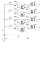
- FIG. 1 shows a configuration example of a communication system including the power supply control device 100 of the first embodiment of the present invention.
- This communication system is used, for example, to provide a service of a public telephone line to a user.
- the present invention can be applied to communication equipment for other purposes.
- the communication system shown in FIG. 1 has a plurality of independent communication facilities 12-1, 12-2, 12-3, and 12-4. Each of these communication facilities 12-1 to 12-4 requires DC power supply to operate.
- the power supply control device 100 supplies power to the communication equipment 12-1 via the load-side power supply line 15-1. Further, the power supply control device 100 supplies power to the communication equipment 12-2 via the load-side power supply line 15-2. Further, the power supply control device 100 supplies power to the communication equipment 12-3 via the load-side power supply line 15-3. Further, the power supply control device 100 supplies power to the communication equipment 12-4 via the load-side power supply line 15-4.
- the main power supply 11 is, for example, a storage battery, and can supply DC power supply to the load side via the power supply line 13 and the ground line 14.
- the power supply control device 100 shown in FIG. 1 starts the operation of a plurality of communication equipments 12-1 to 12-4, these communication equipments 12-1 to 12-4 are used as a load to be controlled and are appropriate.
- Power is supplied from the common main power source 11 to each communication facility 12-1 to 12-4 via the load side power supply lines 15-1 to 15-4 in order and under appropriate conditions.
- FIG. 1 it is assumed that power is supplied to each load from one main power source 11, but for example, a positive electrode main power source and a negative electrode main power source belonging to the same system are used. Power may be supplied to each load from these plurality of main power sources.
- the power supply control device 100 when the operations of the plurality of communication facilities 12-1 to 12-4 to be controlled are stopped, the power supply from the main power supply 11 is supplied in an appropriate order and under appropriate conditions. It is also possible to change the configuration so that it is blocked.
- the power supply control device 100 By appropriately determining the order in which the communication equipments 12-1 to 12-4 are started and the conditions for switching, the power supply control device 100 is in a stable operating state when the communication equipments 12-1 to 12-4 are started. can do. Further, the power supply control device 100 can avoid a large power supply current flowing at the same timing by shifting the timing of starting the power supply power supply to the plurality of communication facilities 12-1 to 12-4, and the main power supply 11 Can be prevented from becoming overloaded. As a result, the power supply control device 100 can avoid malfunctions of the communication equipments 12-1 to 12-4.
- the types and characteristics of the communication equipments 12-1 to 12-4 connected downstream of the load-side power supply lines 15-1 to 15-4 are fixed in advance. It is assumed that there is. Regarding the order of starting the plurality of communication equipments 12-1 to 12-4, the communication equipment 12-1 is the first, the communication equipment 12-2 is the second, the communication equipment 12-3 is the third, and the communication equipment 12 -4 is fixed at the 4th place. Therefore, the power supply start order when starting the plurality of communication facilities 12-1 to 12-4 is fixedly determined by the circuit configuration of the power supply control device 100.
- the power supply line 13 and the load side power supply line 15-1 are connected via a series circuit of the fuse 16-1 and the switch SW1.
- the power supply line 13 and the load side power supply line 15-2 are connected via a series circuit of the fuse 16-2 and the switch SW2.
- the power supply line 13 and the load side power supply line 15-3 are connected to each other via a series circuit of the fuse 16-3 and the switch SW3.
- the power supply line 13 and the load side power supply line 15-4 are connected to each other via a series circuit of the fuse 16-4 and the switch SW4.
- Switches SW1 to SW4 each have contacts that can be individually turned on and off, such as a relay.
- the contact of the switch SW1 is opened as shown in FIG. 1, the power supply power is not supplied to the communication equipment 12-1, and when the contact of the switch SW1 is closed, the power supply power from the main power supply 11 is transferred to the load side power supply line 15-1. It is supplied to the communication equipment 12-1 via the communication equipment 12-1, and the communication equipment 12-1 starts to start.
- the power supply control device 100 shown in FIG. 1 includes four independent monitoring and control units 17-1, 17-2, 17-3, and 17-4.
- the first monitoring and control unit 17-1 controls the on / off of the power supply to the first communication equipment 12-1, which is the load to be controlled. Therefore, the monitoring control unit 17-1 monitors the state of the power supply of the power supply line 13 higher than the load side power supply line 15-1, specifically, the voltage, and adjusts the state to the characteristics of the communication equipment 12-1.
- the control signal SG5 is generated based on the result of comparison with the predetermined conditions, and the switch SW1 is switched on and off. That is, when the voltage of the power supply line 13 satisfies the start-up start condition of the communication equipment 12-1, the monitoring control unit 17-1 closes the contact of the switch SW1 and starts supplying the power supply to the communication equipment 12-1.
- the second monitoring and control unit 17-2 controls the on / off of the power supply to the second communication equipment 12-2, which is the load to be controlled. Therefore, the monitoring control unit 17-2 monitors the load state of the first communication equipment 12-1 itself, that is, the operation state, in which the power supply is started before the communication equipment 12-2, and the operation state thereof is monitored. The state is compared with the conditions determined in advance according to the characteristics of the communication equipment 12-2, and the control signal SG6 is generated based on the result to switch the switch SW2 on and off. That is, the operation state after the first communication equipment 12-1 whose order is set so as to start the start one before the second communication equipment 12-2 is the second communication. When the start-up start condition of the equipment 12-2 is satisfied, the monitoring control unit 17-2 closes the contact of the switch SW2 and starts supplying power to the communication equipment 12-2.
- the third monitoring and control unit 17-3 controls the on / off of the power supply to the third communication equipment 12-3, which is the load to be controlled. Therefore, the monitoring control unit 17-3 monitors the load state of the second communication equipment 12-2 itself, that is, the operation state, in which the power supply is started before the communication equipment 12-3, and the operation state thereof is monitored. The state is compared with the conditions determined in advance according to the characteristics of the communication equipment 12-3, and the control signal SG7 is generated based on the result to switch the switch SW3 on and off. That is, the operation state after the second communication equipment 12-2, whose order is set so as to start the startup one before the third communication equipment 12-3, is the third communication. When the start-up start condition of the equipment 12-3 is satisfied, the monitoring control unit 17-3 closes the contact of the switch SW3 and starts supplying power to the communication equipment 12-3.
- the fourth monitoring and control unit 17-4 controls the on / off of the power supply to the fourth communication equipment 12-4, which is the load to be controlled. Therefore, the monitoring control unit 17-4 monitors the load state of the third communication equipment 12-3 itself, that is, the operating state, in which the power supply is started before the communication equipment 12-4, and that state. Is compared with the conditions predetermined in accordance with the characteristics of the communication equipment 12-4, and the control signal SG8 is generated based on the result to switch the switch SW4 on and off. That is, the operation state after the third communication equipment 12-3, whose order is set so as to start the startup one before the fourth communication equipment 12-4, is the fourth communication. When the start-up start condition of the equipment 12-4 is satisfied, the monitoring control unit 17-4 closes the contact of the switch SW4 and starts supplying power to the communication equipment 12-4.
- the current may be monitored instead of the voltage, both the voltage and the current may be monitored, or either the voltage or the current may be monitored. Fluctuations may be monitored.
- each communication facility 12-1 to 12-4 to be controlled by the power supply control device 100 can output an alarm signal indicating the state when the operating state is not normal.
- each communication facility 12-1 to 12-4 is standard, such as turning on the lamp of the operation unit indicating that the state is normal when the normal operation state is reached, and reflecting the state on the screen display.
- a predetermined signal can be output to the outside using an interface. Therefore, each of the monitoring and control units 17-2 to 17-4 monitors the state of the alarm signal output by the communication equipments 12-1 to 12-3, and whether or not the lamp is lit by using a predetermined sensor or interface. It is assumed that it is configured to monitor the status of the screen display.
- FIG. 2 An operation example of the power supply control device 100 shown in FIG. 1 is shown in FIG.
- the vertical axis represents the ON / OFF state of the switches SW1 to SW3, or the state change of the communication equipments 12-1 to 12-3, and the horizontal axis represents the time t.
- the power supply control device 100 of FIG. 1 switches the switch SW1 from off to on at time t11, switches the switch SW2 from off to on at the subsequent time t21, and switches at the subsequent time t31, as shown in FIG. Switch SW3 from off to on.
- the power supply state of the power supply line 13 monitored by the monitoring control unit 17-1 with the monitoring signal SG1 is compared with the information on the power supply condition held by the monitoring control unit 17-1. It is decided based on.
- each communication facility 12-1 to 12-3 transitions from the off state in which the operation is stopped to the start-up state ST1 by the start of power supply, and is in a stable operation state after a certain period of time. It becomes ST2.
- the length of time that the booting state ST1 continues is not always constant.
- inrush current generally flows through each load-side power supply line 15-1 to 15-3, and the processing load is generally large, so the load on the main power supply 11 is also large. Is assumed.
- the processing load is stable, and the current consumption flowing through the power supply lines 15-1 to 15-3 on each load side is relatively small and stable.
- the state in which the alarm signals output from the communication equipments 12-1 to 12-3 are turned off corresponds to the stable operation state ST2.
- the state of the first communication equipment 12-1 transitions from off to the starting state ST1 at time t11, and after a certain amount of time elapses, that is, at time t12, the state changes from the starting state ST1 to the stable operation state ST2. Transition.
- the second monitoring control unit 17-2 monitors the state of the first communication equipment 12-1, and switches the switch SW2 from off to on when the state reaches a predetermined state. Therefore, after the second monitoring control unit 17-2 detects that the state of the first communication equipment 12-1 has changed from the starting state ST1 to the stable operating state ST2 at the time t12 shown in FIG. 2, for example. Switch SW2 is switched from off to on at time t21.
- the state of the second communication equipment 12-2 transitions from the off state to the starting state ST1 at time t21, and after a certain amount of time elapses, that is, at time t22, the state changes from the starting state ST1 to the stable operation state ST2. Transition.
- the third monitoring control unit 17-3 monitors the state of the second communication equipment 12-2, and switches the switch SW3 from off to on when the state reaches a predetermined state. Therefore, after the third monitoring control unit 17-2 detects that the state of the second communication equipment 12-2 has changed from the starting state ST1 to the stable operating state ST2 at the time t22 shown in FIG. 2, for example. The switch SW3 is switched from off to on at time t31.
- the state of the third communication facility 12-3 transitions from off to the starting state ST1 at time t31, and after a certain amount of time elapses, that is, at time t32, the state changes from the starting state ST1 to the stable operation state ST2. Transition.
- the time t21 shown in FIG. 2 is held by the monitoring control unit 17-2 and the actual operating state of the first communication equipment 12-1 monitored by the monitoring control unit 17-2 with the monitoring signal SG2. Determined based on comparison with information representing load conditions.
- the first communication equipment 12-1 starts to start and enters the stable operation state ST2 after the power supply to the communication equipment 12-1 is started, the lower second communication equipment 12
- the time t21 at which the power supply to -2 is started is surely after the time t11, and the order of activation is not changed. Further, for example, if the fuse 16-1 is disconnected, the communication equipment 12-1 remains stopped even if the switch SW1 is turned on, so that the second lower communication equipment 12-2 is not connected. Power supply Power supply is not started.
- the time t31 shown in FIG. 2 is held by the monitoring control unit 17-3 and the actual operating state of the second communication equipment 12-2 monitored by the monitoring control unit 17-3 with the monitoring signal SG3. Determined based on comparison with information representing load conditions.
- the second communication equipment 12-2 starts to start and enters the stable operation state ST2 after the power supply to the communication equipment 12-2 is started, the lower third communication equipment 12
- the time t31 at which the power supply to -3 is started is surely after the time t21, and the order of activation is not changed. Further, for example, if the fuse 16-2 is disconnected, the communication equipment 12-2 remains stopped even if the switch SW2 is turned on, so that the third lower communication equipment 12-3 is not connected. Power supply Power supply is not started.
- the order of starting power supply to the plurality of communication facilities 12-1 to 12-4 is fixedly determined by the circuit configuration of the power supply control device 100. Therefore, in order to change the order of starting the power supply power supply, it is necessary to change the circuit configuration of the power supply control device 100, that is, the hardware, and the power supply control device 100 cannot be used for general purposes. Therefore, a power supply control device that can be used for general purposes by changing the software will be described below as another embodiment.
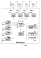
- FIG. 3 shows a configuration example of a communication system including the power supply control device 100B according to the second embodiment of the present invention.
- the components common to the components in FIG. 1 are designated by the same reference numerals. That is, in the communication system of FIG. 3, the configuration other than the power supply control device 100B is the same as that of FIG.
- the communication system shown in FIG. 3 targets a plurality of communication equipments 12-1 to 12-4 as in the communication system of FIG. 1, and the power supply control device 100B in FIG. 3 is the communication equipments 12-1 to 12-12. It has a function to appropriately control the start and stop of power supply to -4.
- the power supply control device 100B in FIG. 3 realizes the same functions as the plurality of monitoring control units 17-1 to 17-4 shown in FIG. 1, but the circuit configuration is changed by controlling with software. It can be used for general purposes without it.
- the power supply control device 100B is, for example, in the main body of a general personal computer, an input interface for monitoring a plurality of monitoring signals SG1 to SG4, an output interface for controlling a plurality of switches SW1 to SW4, and a control device. It can be realized by incorporating the dedicated program and data of.
- the power supply control device 100B includes a higher power supply monitoring unit 26, a plurality of upper load monitoring units 21-1 to 21-3, a load condition comparison unit 22, a non-volatile storage unit 23, and a switching order determination unit 24. , And each function of a plurality of switch control units 25-1 to 25-4. Further, the non-volatile storage unit 23 holds the supply start order data TB1 and the load condition data TB2 for each communication facility as predetermined data.
- the upper power supply monitoring unit 26 shown in FIG. 4 is realized by an electric circuit that processes signals such as the voltage of the monitoring signal SG1, an analog / digital (A / D) converter, a processing function of the computer main body, and monitoring software. can.
- the upper load monitoring units 21-1 to 21-3 have an input interface for capturing alarm signals and the like as monitoring signals SG2 to SG4 from the communication equipments 12-1 to 12-3, a processing function of the computer main body, and a processing function of the computer body. This can be achieved by monitoring software.
- the load condition comparison unit 22 and the switching order determination unit 24 can be realized by a processing function of the computer main body and a program that realizes the processing procedure of the present invention.
- Each switch control unit 25-1 to 25-4 can be configured as an output interface of a computer capable of controlling the on / off of switches SW1 to SW4.
- the supply start order data TB1 is constant data that defines the supply start order of the power supply power to the plurality of communication facilities 12-1 to 12-4 that are the loads to be controlled by the power supply control device 100B. Appropriate values for the contents of the supply start order data TB1 are determined in advance by the designer based on the specifications of the main power supply 11 and the specifications of the communication equipments 12-1 to 12-4, and are stored on the non-volatile storage unit 23. Be retained.
- the load condition data TB2 for each communication facility indicates that the upper load is sufficiently stable for each of the plurality of communication facilities 12-1 to 12-4, which are the loads controlled by the power supply control device 100B. It defines data representing a load condition that can be regarded, for example, a condition necessary for identifying whether or not the condition matches the stable operation state ST2 in which the alarm signal does not appear.
- the supply start order data TB2 for the first communication facility 12-1 defines the power supply conditions such as the voltage for starting the power supply power supply.
- an appropriate value is determined in advance by the designer based on the specifications of the main power supply 11 and the specifications of the communication facilities 12-1 to 12-4, and the non-volatile storage unit. It is held on 23.
- the switching order determination unit 24 determines the supply start order of the power supply power to each of the communication equipments 12-1 to 12-4 according to the contents of the supply start order data TB1 read from the non-volatile storage unit 23.
- the load condition comparison unit 22 controls the switching order of the switches SW1 to SW4 according to the order determined by the switching order determination unit 24, and determines the timing of switching the switches SW1 to SW4, respectively, of the monitoring signals SG1 to SG4.
- the load state at the present time is compared with the content of the load condition data TB2 for each communication facility. Then, the load condition comparison unit 22 sequentially switches the switches SW1 to SW4 on and off according to the comparison result.
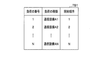
- FIG. 5 shows a configuration example of the supply start order data TB1.
- the supply start order data TB1 shown in FIG. 5 includes numbers 1, 2, ..., N representing each communication equipment 12-1, 12-2, 12-3, ... Which is a load to be controlled.
- Information A1, A2, ..., AN representing the types of each communication equipment 12-1, 12-2, ..., 12-N, and each communication equipment 12-1, 12-2, ..., 12 - contains N sets of data composed of numbers 1, 2, ..., N representing the starting order of N.
- the switching order determination unit 24 can recognize from the contents of the supply start order data TB1 that the power supply should be started in the order of the communication equipments 12-1, 12-2, 12-3, .... Further, by changing the content of the supply start order data TB1, the supply start order of the power supply power can be changed, so that it is possible to correspond to the communication equipment of various specifications without changing the circuit configuration of the power supply start order control device 100B. ..
- the configuration of the supply start order data TB1 can be changed as needed.
- FIG. 6 shows a configuration example of the load condition data TB2 for each communication facility.
- the load condition data TB2 for each communication facility shown in FIG. 6 is the numbers 1, 2, ... Representing each communication facility 12-1, 12-2, 12-3, ... N and information indicating the types of communication equipments 12-1, 12-2, ..., 12-N A1, A2, ..., AN and each communication equipment 12-1, 12-2, ... -Contains N sets of data composed of load conditions for switching the power supply state of 12-N.
- the condition for switching the power supply state to the first communication equipment 12-1 is that the detection of "normal operation” continues for the time T1 in the monitored communication equipment one level higher than that. It is in a state of being.
- the condition for switching the power supply state to the second communication equipment 12-2 is a state in which the detection of "normal operation” is continued for the time T2 in the monitored communication equipment one level higher than the condition. The same applies to other communication equipment, and conditions for switching individually are set.
- the load that starts power supply first is not higher than that, so it is mainly used instead of the data representing the load condition.
- Data that defines power supply conditions such as the output voltage of the power supply 11 is adopted.
- the power supply control device 100B receives a monitoring signal input from the upper load monitoring unit 21-1.
- the actual operating state of the corresponding load is grasped from SG2, and the switch SW2 is switched when the state in which "normal operation" is detected continues for the time T2.
- the power supply control device 100B can individually change the load condition for starting the power supply power supply for each communication facility. Therefore, even if the specifications of the communication system to be controlled are changed, the power supply control device 100B can appropriately respond only by changing the load condition data TB2 for each communication facility.
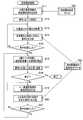
- FIG. 7 shows a procedure for power supply start control in the power supply control device 100B according to the second embodiment of the present invention. That is, the main body of the computer that realizes the power supply control device 100B shown in FIG. 4 executes the control program corresponding to the contents of FIG. 7, and thereby N communication equipments 12-1 to 12-1 to the load to be controlled. Appropriately control the start of supply of power to 12-N. In the example of FIG. 4, it is assumed that only four communication facilities 12-1 to 12-4 are controlled, but the number of required components increases or decreases according to the change of the total number N of the devices to be controlled. can.
- the power supply control device 100B uses, for example, the supply start order data TB1 shown in FIGS. 4 to 6 and the load condition data TB2 for each communication facility.
- the procedure shown in FIG. 7 will be described below.
- the switching order determination unit 24 reads the contents of the supply start order data TB1 and specifies the supply start order of N communication equipments according to the contents.
- the power supply condition comparison unit 22 initializes the number n for specifying the processing target from the communication equipment of the N system or the like to “1”.
- step S13 since the communication equipment of the first system in which the upper load does not exist is processed, the load condition comparison unit 22 uses the upper power supply monitoring unit 26 to set the voltage of the power supply line 13 instead of the load state. It is sequentially input as the voltage Vx of the monitoring signal SG1.
- step S14 the load condition comparison unit 22 refers to the condition of the first system in the load condition data TB2 for each communication facility, and compares this condition with the monitoring voltage Vx input in step S13. If the comparison result does not satisfy the condition, the processes of steps S13 to S15 are repeated, and if the comparison result satisfies the condition, the process proceeds from step S15 to S16.
- step S16 the load condition comparison unit 22 closes the contacts of the switch SWn whose switching order is n among the switches SW1, SW2, ... Any of the above is controlled, and the power supply to the nth communication facility 12-n is started.
- the nth communication equipment 12-n can start the operation.
- step S17 the load condition comparison unit 22 adds 1 to the number n to update the contents.
- step S18 the load condition comparison unit 22 identifies whether or not the processing for all the communication equipment to be controlled has been completed, and if not, proceeds to the next processing in step S19 and thereafter, and continues processing until the processing is completed. repeat.
- a signal representing the load state, specifically the operating state, is input from the m-th upper load monitoring unit 21-m and monitored.
- step S20 the load condition comparison unit 22 acquires the switching condition of the power supply assigned to the nth communication equipment to be processed this time from the load condition data TB2 for each communication equipment, and compares it with the load state in step S19. If the comparison result in step S20 does not satisfy the conditions, the processes of steps S19 to S21 are repeated, and if the conditions are satisfied, the process proceeds from steps S21 to S16, and the nth switch is closed.
- the switches SW1, SW2, ... can be switched in the same manner as in FIG. 2, for example, in a predetermined order and in a predetermined load. It is possible to control the start of supply of power to a plurality of communication facilities 12-1, 12-2, ... At the timing according to the conditions. Therefore, it becomes easy to start each of the plurality of communication facilities 12-1 to 12-4 included in the communication system in a stable state, the main power supply 11 becomes overloaded, and the output of the main power supply 11 is unsuccessful. You can avoid becoming stable.
- FIG. 8 shows a procedure for power supply stop control in the power supply control device 100B according to the second embodiment of the present invention. That is, when the main body of the computer that realizes the power supply control device 100B shown in FIG. 4 executes the control program corresponding to the contents of FIG. 8, N communication equipments 12-1 to 12-1 to which are the loads to be controlled. Appropriately control the suspension of power supply to 12-N.
- the power supply control device 100B uses the supply end order data TB3 instead of the supply start order data TB1 shown in FIG. 4, and the content is different from the load condition data TB2 for each communication facility.
- the load condition data TB4 for each facility is used.
- the supply end order data TB3 used in the procedure of FIG. 8 is configured to hold, for example, data having a number representing the “stop order” instead of the “start order” in the supply start order data TB1 shown in FIG. NS.
- the load condition data TB4 for each communication facility used in the procedure of FIG. 8 is a load when each switch is switched from closed to open as a "load condition" in the load condition data TB2 for each communication facility shown in FIG. It is configured to hold condition data.
- the switching order determination unit 24 reads the contents of the supply end order data TB3 and specifies the supply end order of N communication equipments according to the contents.
- the load condition comparison unit 22 initializes the number n for specifying the processing target from the communication equipment and the like of the N system to “1”.
- the load condition comparison unit 22 uses the upper power supply monitoring unit 26 to set the voltage of the power supply line 13 and the voltage of the monitoring signal SG1. Input sequentially as Vx.
- step S14B the load condition comparison unit 22 refers to the condition of the first system in the load condition data TB4 for each communication facility, and compares this condition with the monitoring voltage Vx input in step S13. If the comparison result does not satisfy the condition, the processes of steps S13 to S15 are repeated, and if the comparison result satisfies the condition, the process proceeds from step S15 to S16B.
- step S16B the load condition comparison unit 22 opens the contacts of the switch SWn whose switching order is n among the switches SW1, SW2, .... Any of the above is controlled, and the power supply to the nth communication facility 12-n is terminated.
- the operation of the nth communication facility 12-n is stopped.
- step S17 the load condition comparison unit 22 adds 1 to the number n to update the contents.
- step S18 the load condition comparison unit 22 identifies whether or not the processing for all the communication equipment to be controlled has been completed, and if not, proceeds to the next processing in step S19 and thereafter, and continues processing until the processing is completed. repeat.
- step S20B the load condition comparison unit 22 acquires the switching condition of the power supply assigned to the nth communication equipment to be processed this time from the load condition data TB4 for each communication equipment, and compares it with the load state in step S19. If the comparison result in step S20B does not satisfy the conditions, the processes of steps S19 to S21 are repeated, and if the conditions are satisfied, the process proceeds from steps S21 to S16, and the nth switch is opened.
- the switches SW1, SW2, ... Can be switched in order from on to off, and can be switched in advance. It is possible to control the stoppage of power supply to a plurality of communication facilities 12-1, 12-2, ... In a predetermined order and at a timing according to a predetermined load condition. Therefore, it becomes easy to stop each of the plurality of communication facilities 12-1 to 12-4 included in the communication system in a stable state.
- FIG. 7 A modified example of the “supply start control” shown in FIG. 7 is shown in FIG. That is, when the main body of the computer that realizes the power supply control device 100B shown in FIG. 4 executes the control program corresponding to the contents of FIG. 9, N communication equipments 12-1 to 12-1 to which are the loads to be controlled. Appropriately control the start of supply of power to 12-N.
- the power supply control device 100B uses the load condition data TB2B for each communication equipment whose contents are different from the load condition data TB2 for each communication equipment shown in FIG.
- the load condition data TB2B for each communication facility used in the procedure of FIG. 9 has the load condition comparison unit 22 "normal operation" as the "load condition” in the power supply condition data TB2 for each communication facility shown in FIG.
- steps common to the procedure in FIG. 7 are shown with the same step numbers.
- the procedure shown in FIG. 9 will be described below.
- the computer main body of the power supply control device 100B executes the operation already described.
- step S14C of FIG. 9 the load condition comparison unit 22 refers to the condition of the first system of the load condition data TB2B for each communication facility, and determines in advance the elapsed time after the monitoring voltage Vx becomes a normal value. Compare with the conditions. If the comparison result does not satisfy the condition, the processes of steps S13 to S15 are repeated, and if the comparison result satisfies the condition, the process proceeds from step S15 to S16.
- step S20C of FIG. 9 the load condition comparison unit 22 acquires the load condition assigned to the nth communication equipment to be processed this time from the load condition data TB2B for each communication equipment and compares it with the monitoring state. That is, the load condition comparison unit 22 identifies whether or not the state of the upper load is "normal operation", and further determines whether or not the elapsed time after recognizing "normal operation" has reached a predetermined time. Identify. If the comparison result of step S20C does not satisfy the condition, the processes of steps S19 to S21 are repeated, and when the condition is satisfied, the process proceeds from step S21 to S16, and the nth switch is closed.
- the switches SW1, SW2, ... can be switched in the same manner as in FIG. 2, for example, in a predetermined order and in a predetermined load. It is possible to control the start of supply of power to a plurality of communication facilities 12-1, 12-2, ... At the timing according to the conditions. Therefore, it becomes easy to start each of the plurality of communication facilities 12-1 to 12-4 included in the communication system in a stable state, the main power supply 11 becomes overloaded, and the output of the main power supply 11 is unsuccessful. You can avoid becoming stable.
- the communication equipment 12-1 to 12-4 which is the load to be controlled, is supplied by the configuration of the circuit connection state of the plurality of monitoring and control units 17-1 to 17-4.
- Power supply The order in which power supply is started can be fixed in advance. Further, the conditions for starting the power supply and the conditions for stopping the power supply can be determined in advance and incorporated into the monitoring and control units 17-1 to 17-4. Further, since each monitoring control unit 17-1 to 17-4 monitors the state of the upper load whose state is switched before the load to be controlled, the communication equipment of the communication equipment is started to be energized to one load.
- the energization of the next load can be started. Therefore, it is less likely to be affected by the inrush current flowing through the load at the start of energization, and even if the power capacity of the main power supply 11 does not have a large margin, it is possible to start a plurality of loads in a stable state. Further, when each fuse 16-1 to 16-4 is disconnected, it can be reflected in the control.
- the power supply control device 100B shown in FIG. 3 can be used to control communication equipment having various specifications without changing the circuit configuration. That is, the order of starting the power supply to the communication equipments 12-1 to 12-4, which are the loads to be controlled, is determined by the supply start order data TB1 shown in FIG. 4, and the condition for starting the power supply is determined by the communication equipment. Since it is determined by the load condition data TB2 for each, it can be applied to various uses only by modifying the data by using common hardware.
- the load condition data TB2 for each communication facility shown in FIG. 6 as a load condition for starting the power supply of the load, a condition indicating whether or not the operating state of the upper load is normal operation.
- stable control becomes possible. For example, when identifying the energization start condition of the second communication equipment 12-2, the communication equipment 12-1 is stable when the first communication equipment 12-1 above it does not output an alarm signal. It is considered that the operating state is the same, the processing load is stable, and the load current and the power supply voltage flowing through the main power supply 11 are also stable. Therefore, the timing at which the first communication equipment 12-1 satisfies the load condition that can be regarded as normal operation is an appropriate timing for starting the energization of the second communication equipment 12-2.
- each step S20C, S21 and S16 are executed, and energization of the load to be controlled is started. Therefore, it is possible to increase the stability of control. For example, even if an alarm signal is intermittently output from the upper load after the energization of the upper load is started, the state of the upper load is sufficiently stabilized by further waiting until a predetermined time elapses. After that, energization to the lower load can be started. Therefore, the operations of the plurality of communication equipments 12-1 to 12-4 can be activated in a stable state without human intervention in the operation.
- the load condition data TB2 for each communication equipment shown in FIG. 6 includes data for the load condition independent for each communication equipment, the condition indicating the load state at the time of starting energization is set for each communication equipment. It is possible to optimize according to the unique characteristics of.
Landscapes
- Engineering & Computer Science (AREA)
- Power Engineering (AREA)
- Business, Economics & Management (AREA)
- Emergency Management (AREA)
- Remote Monitoring And Control Of Power-Distribution Networks (AREA)
- Direct Current Feeding And Distribution (AREA)
Priority Applications (3)
| Application Number | Priority Date | Filing Date | Title |
|---|---|---|---|
| PCT/JP2020/008406 WO2021171579A1 (ja) | 2020-02-28 | 2020-02-28 | 通信設備の電源供給制御装置、電源供給制御方法、電源供給制御プログラム、及び電源供給制御システム |
| JP2022503021A JP7375907B2 (ja) | 2020-02-28 | 2020-02-28 | 通信設備の電源供給制御装置、電源供給制御方法、電源供給制御プログラム、及び電源供給制御システム |
| US17/802,205 US11901728B2 (en) | 2020-02-28 | 2020-02-28 | Communication facilities power supply control device, power supply control method, power supply control program, and power supply control system |
Applications Claiming Priority (1)
| Application Number | Priority Date | Filing Date | Title |
|---|---|---|---|
| PCT/JP2020/008406 WO2021171579A1 (ja) | 2020-02-28 | 2020-02-28 | 通信設備の電源供給制御装置、電源供給制御方法、電源供給制御プログラム、及び電源供給制御システム |
Publications (1)
| Publication Number | Publication Date |
|---|---|
| WO2021171579A1 true WO2021171579A1 (ja) | 2021-09-02 |
Family
ID=77492086
Family Applications (1)
| Application Number | Title | Priority Date | Filing Date |
|---|---|---|---|
| PCT/JP2020/008406 Ceased WO2021171579A1 (ja) | 2020-02-28 | 2020-02-28 | 通信設備の電源供給制御装置、電源供給制御方法、電源供給制御プログラム、及び電源供給制御システム |
Country Status (3)
| Country | Link |
|---|---|
| US (1) | US11901728B2 (https=) |
| JP (1) | JP7375907B2 (https=) |
| WO (1) | WO2021171579A1 (https=) |
Families Citing this family (1)
| Publication number | Priority date | Publication date | Assignee | Title |
|---|---|---|---|---|
| WO2021171559A1 (ja) * | 2020-02-28 | 2021-09-02 | 日本電信電話株式会社 | 通信設備の電源供給制御装置、電源供給制御方法、電源供給制御プログラム、及び電源供給制御システム |
Citations (3)
| Publication number | Priority date | Publication date | Assignee | Title |
|---|---|---|---|---|
| JPH04134994A (ja) * | 1990-09-26 | 1992-05-08 | Meisei Electric Co Ltd | 電話交換システムの立ち上げ方法 |
| JP2014192994A (ja) * | 2013-03-27 | 2014-10-06 | Nec Network Products Ltd | 電源供給装置 |
| JP2016045656A (ja) * | 2014-08-21 | 2016-04-04 | 京セラドキュメントソリューションズ株式会社 | 電源管理回路及びこれを備えた画像形成装置 |
Family Cites Families (3)
| Publication number | Priority date | Publication date | Assignee | Title |
|---|---|---|---|---|
| JPS50151422A (https=) * | 1974-05-27 | 1975-12-05 | ||
| JP3267232B2 (ja) * | 1998-02-23 | 2002-03-18 | 日本電気株式会社 | 突入電流抑圧用の電源制御方法および電源制御装置 |
| US10742030B2 (en) * | 2018-01-12 | 2020-08-11 | Katerra Inc. | Dynamic load balancing |
-
2020
- 2020-02-28 JP JP2022503021A patent/JP7375907B2/ja active Active
- 2020-02-28 WO PCT/JP2020/008406 patent/WO2021171579A1/ja not_active Ceased
- 2020-02-28 US US17/802,205 patent/US11901728B2/en active Active
Patent Citations (3)
| Publication number | Priority date | Publication date | Assignee | Title |
|---|---|---|---|---|
| JPH04134994A (ja) * | 1990-09-26 | 1992-05-08 | Meisei Electric Co Ltd | 電話交換システムの立ち上げ方法 |
| JP2014192994A (ja) * | 2013-03-27 | 2014-10-06 | Nec Network Products Ltd | 電源供給装置 |
| JP2016045656A (ja) * | 2014-08-21 | 2016-04-04 | 京セラドキュメントソリューションズ株式会社 | 電源管理回路及びこれを備えた画像形成装置 |
Also Published As
| Publication number | Publication date |
|---|---|
| US20230089749A1 (en) | 2023-03-23 |
| JP7375907B2 (ja) | 2023-11-08 |
| US11901728B2 (en) | 2024-02-13 |
| JPWO2021171579A1 (https=) | 2021-09-02 |
Similar Documents
| Publication | Publication Date | Title |
|---|---|---|
| JP5263933B2 (ja) | マルチ電源装置、該装置に用いられる電力供給方法、及び電力供給制御プログラム | |
| US7350088B2 (en) | Power management system for UPS attached to external devices | |
| US20060039290A1 (en) | Systems and methods for automatic public switched telephone network backup of Voice over Internet Protocol services | |
| CN103246579A (zh) | 基板管理控制器系统 | |
| WO2021171579A1 (ja) | 通信設備の電源供給制御装置、電源供給制御方法、電源供給制御プログラム、及び電源供給制御システム | |
| JP7375906B2 (ja) | 通信設備の電源供給制御装置、電源供給制御方法、電源供給制御プログラム、及び電源供給制御システム | |
| JP2001184142A (ja) | 電源装置及び電源システム | |
| CN114123724B (zh) | 开关电源系统的控制方法和开关电源系统 | |
| US10637672B2 (en) | Apparatus and methods of power over ethernet | |
| WO2018103221A1 (zh) | 供电电路切换的装置及方法 | |
| CN108256359B (zh) | 一种存储硬盘供电保护系统及保护方法 | |
| CN111309132B (zh) | 一种服务器多档位电源冗余的方法 | |
| KR101489819B1 (ko) | 이중화된 cpu를 포함하는 원보드 ddc 시스템 | |
| US9209678B2 (en) | Power converter system providing a load with electrical power | |
| JP2016181179A (ja) | 電源切替装置、電源システム、電源切替方法、及び電源切替プログラム | |
| JP2000022698A (ja) | 車両ネットワークシステム及び車両機器状態制御方法 | |
| JP2010509902A (ja) | Ups自動監視システム及びこれを利用した自動復旧方法 | |
| JP2012230231A (ja) | 表示制御装置及びその制御方法 | |
| JP3360015B2 (ja) | 電源立ち上げ方法および電源立ち上げ装置 | |
| JP5146888B2 (ja) | サーバ装置及びその制御方法 | |
| JP2015119526A (ja) | 電力供給装置 | |
| CN111416719A (zh) | 可透过网络唤醒的服务器装置及其方法 | |
| JPS59148968A (ja) | 自動運転装置 | |
| JP2007156744A (ja) | 分散監視制御システム | |
| JP2025126840A (ja) | 充放電制御方法及び充放電制御装置 |
Legal Events
| Date | Code | Title | Description |
|---|---|---|---|
| 121 | Ep: the epo has been informed by wipo that ep was designated in this application |
Ref document number: 20921736 Country of ref document: EP Kind code of ref document: A1 |
|
| ENP | Entry into the national phase |
Ref document number: 2022503021 Country of ref document: JP Kind code of ref document: A |
|
| NENP | Non-entry into the national phase |
Ref country code: DE |
|
| 122 | Ep: pct application non-entry in european phase |
Ref document number: 20921736 Country of ref document: EP Kind code of ref document: A1 |