WO2021171403A1 - 空中映像表示装置 - Google Patents
空中映像表示装置 Download PDFInfo
- Publication number
- WO2021171403A1 WO2021171403A1 PCT/JP2020/007632 JP2020007632W WO2021171403A1 WO 2021171403 A1 WO2021171403 A1 WO 2021171403A1 JP 2020007632 W JP2020007632 W JP 2020007632W WO 2021171403 A1 WO2021171403 A1 WO 2021171403A1
- Authority
- WO
- WIPO (PCT)
- Prior art keywords
- aerial
- image
- observer
- image display
- light
- Prior art date
- Legal status (The legal status is an assumption and is not a legal conclusion. Google has not performed a legal analysis and makes no representation as to the accuracy of the status listed.)
- Ceased
Links
Images



Classifications
-
- G—PHYSICS
- G02—OPTICS
- G02B—OPTICAL ELEMENTS, SYSTEMS OR APPARATUS
- G02B30/00—Optical systems or apparatus for producing three-dimensional [3D] effects, e.g. stereoscopic images
- G02B30/50—Optical systems or apparatus for producing three-dimensional [3D] effects, e.g. stereoscopic images the image being built up from image elements distributed over a three-dimensional [3D] volume, e.g. voxels
- G02B30/56—Optical systems or apparatus for producing three-dimensional [3D] effects, e.g. stereoscopic images the image being built up from image elements distributed over a three-dimensional [3D] volume, e.g. voxels by projecting aerial or floating images
-
- G—PHYSICS
- G02—OPTICS
- G02B—OPTICAL ELEMENTS, SYSTEMS OR APPARATUS
- G02B27/00—Optical systems or apparatus not provided for by any of the groups G02B1/00 - G02B26/00, G02B30/00
- G02B27/0093—Optical systems or apparatus not provided for by any of the groups G02B1/00 - G02B26/00, G02B30/00 with means for monitoring data relating to the user, e.g. head-tracking, eye-tracking
-
- G—PHYSICS
- G03—PHOTOGRAPHY; CINEMATOGRAPHY; ANALOGOUS TECHNIQUES USING WAVES OTHER THAN OPTICAL WAVES; ELECTROGRAPHY; HOLOGRAPHY
- G03B—APPARATUS OR ARRANGEMENTS FOR TAKING PHOTOGRAPHS OR FOR PROJECTING OR VIEWING THEM; APPARATUS OR ARRANGEMENTS EMPLOYING ANALOGOUS TECHNIQUES USING WAVES OTHER THAN OPTICAL WAVES; ACCESSORIES THEREFOR
- G03B35/00—Stereoscopic photography
- G03B35/18—Stereoscopic photography by simultaneous viewing
-
- G—PHYSICS
- G09—EDUCATION; CRYPTOGRAPHY; DISPLAY; ADVERTISING; SEALS
- G09G—ARRANGEMENTS OR CIRCUITS FOR CONTROL OF INDICATING DEVICES USING STATIC MEANS TO PRESENT VARIABLE INFORMATION
- G09G5/00—Control arrangements or circuits for visual indicators common to cathode-ray tube indicators and other visual indicators
-
- H—ELECTRICITY
- H04—ELECTRIC COMMUNICATION TECHNIQUE
- H04N—PICTORIAL COMMUNICATION, e.g. TELEVISION
- H04N13/00—Stereoscopic video systems; Multi-view video systems; Details thereof
- H04N13/10—Processing, recording or transmission of stereoscopic or multi-view image signals
- H04N13/106—Processing image signals
- H04N13/122—Improving the three-dimensional [3D] impression of stereoscopic images by modifying image signal contents, e.g. by filtering or adding monoscopic depth cues
-
- H—ELECTRICITY
- H04—ELECTRIC COMMUNICATION TECHNIQUE
- H04N—PICTORIAL COMMUNICATION, e.g. TELEVISION
- H04N13/00—Stereoscopic video systems; Multi-view video systems; Details thereof
- H04N13/30—Image reproducers
- H04N13/346—Image reproducers using prisms or semi-transparent mirrors
-
- H—ELECTRICITY
- H04—ELECTRIC COMMUNICATION TECHNIQUE
- H04N—PICTORIAL COMMUNICATION, e.g. TELEVISION
- H04N13/00—Stereoscopic video systems; Multi-view video systems; Details thereof
- H04N13/30—Image reproducers
- H04N13/366—Image reproducers using viewer tracking
-
- G—PHYSICS
- G02—OPTICS
- G02B—OPTICAL ELEMENTS, SYSTEMS OR APPARATUS
- G02B27/00—Optical systems or apparatus not provided for by any of the groups G02B1/00 - G02B26/00, G02B30/00
- G02B27/0018—Optical systems or apparatus not provided for by any of the groups G02B1/00 - G02B26/00, G02B30/00 with means for preventing ghost images
-
- G—PHYSICS
- G03—PHOTOGRAPHY; CINEMATOGRAPHY; ANALOGOUS TECHNIQUES USING WAVES OTHER THAN OPTICAL WAVES; ELECTROGRAPHY; HOLOGRAPHY
- G03B—APPARATUS OR ARRANGEMENTS FOR TAKING PHOTOGRAPHS OR FOR PROJECTING OR VIEWING THEM; APPARATUS OR ARRANGEMENTS EMPLOYING ANALOGOUS TECHNIQUES USING WAVES OTHER THAN OPTICAL WAVES; ACCESSORIES THEREFOR
- G03B21/00—Projectors or projection-type viewers; Accessories therefor
- G03B21/14—Details
-
- G—PHYSICS
- G03—PHOTOGRAPHY; CINEMATOGRAPHY; ANALOGOUS TECHNIQUES USING WAVES OTHER THAN OPTICAL WAVES; ELECTROGRAPHY; HOLOGRAPHY
- G03B—APPARATUS OR ARRANGEMENTS FOR TAKING PHOTOGRAPHS OR FOR PROJECTING OR VIEWING THEM; APPARATUS OR ARRANGEMENTS EMPLOYING ANALOGOUS TECHNIQUES USING WAVES OTHER THAN OPTICAL WAVES; ACCESSORIES THEREFOR
- G03B21/00—Projectors or projection-type viewers; Accessories therefor
- G03B21/54—Accessories
- G03B21/56—Projection screens
- G03B21/60—Projection screens characterised by the nature of the surface
- G03B21/62—Translucent screens
Definitions
- the present disclosure relates to an aerial image display device that displays an image in the air without a display element.
- the arrangement structure is such that the aerial image is projected onto the space on the movement line through which the observer passes, the image, which is unnecessary light that does not become an image immediately after passing the imaging position of the aerial image perceived by the observer, is displayed.
- the light before the image is formed in the space is visually recognized by the observer.
- the present disclosure has been made to solve the above-mentioned problems, and it is possible for an observer to perceive an aerial image with an appropriate display quality without visually recognizing the light before forming the image in space. Is to be.
- the present disclosure discloses an image display unit that displays an image, an aerial imaging optical system that reflects diffused light emitted from the image display unit a plurality of times and transmits the diffused light to reimage the image in different spaces, and aerial imaging optics.
- the observer is in the area between the viewpoint position information acquisition unit that acquires the viewpoint position information of the observer who sees the point where the diffused light is reimaged by the system, and the aerial imaging optical system and the point where the diffused light is reimaged. It is characterized by including a display control processing unit that blocks diffused light from the image display unit when it is detected to be present.
- an aerial image display device that forms an aerial image
- an arrangement structure that projects an aerial image into a space on a movement line through which an observer passes, even if the observer is immediately after passing through the aerial image
- the aerial connection is established.
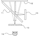
- FIG. It is explanatory drawing which shows the structure of the aerial image display device 100 of Embodiment 1.
- FIG. It is explanatory drawing which shows until the light from the image display part 10 of Embodiment 1 forms an image in the air.
- It is a block diagram which shows the structure of the display control device 15 of Embodiment 1.
- FIG. It is explanatory drawing which shows the control example in the case where the observer 19 is closer to the beam splitter 11 than the imaging range of the aerial image 13 in Embodiment 1.
- FIG. It is a block diagram which shows the structure of the display control device 15a of Embodiment 2.
- FIG. It is explanatory drawing which shows the control example in the case where the observer 19 is a position farther from the beam splitter 11 and is close to the image formation range of the aerial image 13 in Embodiment 2.
- FIG. It is explanatory drawing which shows the area 31a and area 31b in the image display part 10 of Embodiment 2.
- It is explanatory drawing which shows the area 31a, area 31b, area 31c and area 31d in the image display part 10 of Embodiment 2.
- FIG. 1 is an explanatory diagram showing the configuration of the aerial image display device 100 according to the first embodiment of the present disclosure.
- the aerial image display device 100 includes an image display unit 10, a beam splitter 11, a retroreflective sheet 12, a viewpoint position detection device 14, and a display control device 15.
- the beam splitter 11 and the retroreflective sheet 12 constitute an aerial imaging optical system that reflects diffused light emitted from the image display unit 10 a plurality of times and transmits the diffused light to reimage it in a different space.
- the image display unit 10 sends the displayed image as light to the beam splitter 11.
- the beam splitter 11 reflects the light from the image display unit 10 and sends it to the retroreflective sheet 12.
- the retroreflective sheet 12 reflects the light from the beam splitter 11 and sends it to the beam splitter 11.
- the beam splitter 11 transmits the light from the retroreflective sheet 12.
- the light transmitted through the retroreflective sheet 12 is perceived by the observer 19 as an aerial image 13.
- the viewpoint position detecting device 14 provides information on detecting the viewpoint position of the observer 19. It is sent to the display control device 15.
- the display control device 15 has a function of controlling the display light from the image display unit 10 from the information of the viewpoint position detection device 14.
- the video display unit 10 is a device in which a video input signal is input from, for example, a signal generator or a video playback device, and the displayed video is output as light.
- a display device having a liquid crystal element and a backlight such as a liquid crystal display, a display device of a self-luminous device using an organic EL element or an LED element, or a projection device using a projector and a screen. Be done.
- a display using a curved surface, a three-dimensionally arranged display, a three-dimensional display such as an LED, or a lens optical system or barrier control the observer can see both eyes.
- a display that perceives a stereoscopic image due to parallax or motion parallax may be used.
- the beam splitter 11 is an optical element that separates incident light into transmitted light and reflected light.
- the beam splitter 11 is, for example, an acrylic plate or a glass plate. Acrylic plates and glass plates generally have higher transmitted light intensity than reflected light, so even if you use an optical element that is a half mirror with metal added to the acrylic plate or glass plate to improve the reflected intensity. good.
- a reflective polarizing plate may be used in which the behavior of reflection and the behavior of transmission change depending on the polarization state of the incident light by the liquid crystal element or the thin film element.
- a reflective polarizing plate may be used in which the ratio of the transmittance and the reflectance changes depending on the polarized state of the incident light depending on the liquid crystal element or the thin film element.
- the retroreflective sheet 12 is a sheet-like optical element having retroreflective performance that reflects incident light as it is in the incident direction.
- the optical element that realizes retroreflection is a bead-type optical element in which small glass beads are laid out in a mirror surface, and a convex minute triangular pyramid or a shape in which the central part of the triangular pyramid is cut out, each surface of which is composed of a mirror surface.
- micro-prism type optical elements etc.
- FIG. 2 is an explanatory diagram showing how the light from the image display unit 10 of the first embodiment of the present disclosure forms an image in the air.
- the beam splitter 11 and the retroreflection sheet 12 are arranged in pairs with the image display unit 10.
- the light of the image from the image display unit 10 is reflected by the beam splitter 11, and this light is retroreflected by the retroreflective sheet 12, so that the solid line and the dotted line showing the optical path of the light of the image from the image display unit 10 in FIG.
- Light re-converges in the air so that and converges to one point. Since the observer 19 can visually recognize the reconverged light, it is perceived that the image exists at the position of the aerial image 13.
- the observer 19 is not limited to the structure described above as long as the structure perceives that the image exists at the position of the aerial image 13.
- a structure using a two-sided corner reflector array may be used. The light incident on one mirror surface of this structure is reflected by the other mirror surface, and the light reaches the target position with respect to this element structure. Light that is similarly reflected by a similarly diffused light source can be perceived as an aerial image by reconverging as in FIG.
- the viewpoint position detecting device 14 detects the viewpoint position.
- the viewpoint position is, for example, the position where the eyes of the observer 19 exist.
- the viewpoint position detecting device 14 is an imaging device such as a camera.
- the viewpoint position detecting device 14 detects the viewpoint position by acquiring the three-dimensional position information of the observer 19 with, for example, a compound eye camera.
- the viewpoint position detection device 14 detects the viewpoint position from three-dimensional position estimation by optical flow and feature points of the face and skeleton even in the case of a monocular camera having only a visible light region, for example.
- the viewpoint position detection device 14 detects the viewpoint position information 20 by acquiring the reflection pattern and speed of the infrared light by a camera that captures infrared light and a device that irradiates infrared light.
- the viewpoint position information 20 is, for example, information indicating the position where the eyes of the observer 19 exist. Further, the viewpoint position detecting device 14 irradiates a waveform that spreads in a three-dimensional space such as a radio wave or a magnetic field or sound as a method other than using a camera imaging element, and a device that inputs the wave acquires the irradiation waveform. There is a method of estimating the viewpoint position information 20 of a person according to the time and pattern of the operation. Further, the viewpoint position detecting device 14 acquires the viewpoint position information 20 from the position where the observer is standing by providing a pressure sensor at the foot of a place where the observer is assumed to be.
- FIG. 3 is a block diagram showing the configuration of the display control device 15.
- the display control device 15 includes an aerial imaging range estimation unit 16 and a display control processing unit 18.
- the display control device 15 receives the viewpoint position information 20 and controls the display.
- the aerial imaging range estimation unit 16 inputs the viewpoint position information 20 and the aerial imaging structure information 21, and outputs the aerial imaging range information 22 to the display control processing unit 18.
- the aerial imaging range information 22 is position information that three-dimensionally indicates the position where the aerial image is formed.
- the aerial imaging structure information 21 is information representing the positional relationship between the image display unit 10, the beam splitter 11, and the optical system members of the retroreflection sheet 12, which are necessary for forming the aerial image 13.
- the display control processing unit 18 inputs the aerial imaging range information 22 and the display video information 24, and controls the display light.
- the processing contents in each block will be described below. As a factor that lowers the image perceived by the observer 19, light other than the light forming the aerial image 13 is visually recognized.
- the aerial imaging range estimation unit 16 is composed of the viewpoint position information 20 obtained from the viewpoint position information detection unit and the aerial imaging structure information 21 having an optical arrangement structure for forming an aerial image in the aerial image display device 100. An image range of an aerial image that can be perceived by the observer 19 is estimated.
- the aerial imaging range estimation unit 16 can perform the aerial image in the display area output by the image display unit 10.
- the range perceived by the observer 19 can be estimated as.
- the viewpoint position information 20 of the observer 19 is detected and output by the viewpoint position detecting device 14. Further, the aerial imaging range information 22 is output from the aerial imaging range estimation unit 16.
- the viewpoint position of the observer 19 is closer to the beam splitter 11 than the image formation position of the aerial image 13 after the observer 19 passes through the image formation position of the aerial image 13, in other words, the observer 19 moves.
- the aerial imaging optical system and the diffused light are reimaged from the region connected to the point where the diffused light is reimaged by the aerial imaging optical system composed of the beam splitter 11 and the retroreflective sheet 12. When moving to the area between the points, it is estimated that the observer 19 will not be able to perceive the aerial image 13.
- the optical path is formed by reflecting the incident optical path once on each mirror surface. Therefore, it is presumed that the observer 19 does not perceive it as an aerial image when the reflection is performed once or less or three times or more due to the relationship between the structure and the incident angle of the light source.
- the display control processing unit 18 controls to block the optical path for forming the aerial image 13 from the aerial image formation range information 22 and the display image information 24.
- Examples of the light-shielding control method include control by turning off the image display unit 10.
- the shading control method includes control by turning off a backlight portion such as a liquid crystal display in the image display unit 10.
- control by turning off each light source of an organic EL display, an LED display, or the like in the image display unit 10 can be mentioned.
- the shading control method includes control by editing the values of all pixels of the display video information 24 to zero.
- a light-shielding control method for example, an optical film or a physical light-shielding device may be used.
- the light-shielding device is installed on the optical path until the light emitted by the image display unit 10 reaches the observer 19 as an aerial image 13, and the light-shielding device can be controlled by an electronic shutter or a curtain. Further, as a shading control method, for example, the value of all pixels of the video input signal may be changed to zero and supplied to the video display unit 10.
- FIG. 4 is an explanatory diagram showing a control example when the observer 19 is closer to the beam splitter 11 than the position of the aerial image 13. Since the optical path before forming an image on the aerial image 13 is visually recognized, as a control, the area of the light visually recognized by the observer 19 is shaded as the display shading area 31, so that the image light which becomes unpleasant light is visually recognized. Eliminate the discomfort caused by this.
- aerial image display device configured in this way, light that is visually unpleasant for the observer is generated by blocking the optical path that forms the image of the aerial image 13 from the result of estimating the deterioration of the image quality of the aerial image 13. Only aerial images can be perceived with appropriate display quality without being visually recognized.
- Embodiment 2 In the present embodiment, an image quality conversion process for estimating the image quality of the aerial image 13 visually recognized by the observer 19 and controlling the display image quality will be described.
- FIG. 5 is a block diagram showing the configuration of the display control device 15a.
- the display control device 15a includes an aerial imaging range estimation unit 16, an aerial image visual estimation unit 17, and a display control processing unit 18a.
- the display control device 15a receives the viewpoint position information 20, the aerial imaging structure information 21, and the display video information 24, and controls the display.
- the aerial imaging range estimation unit 16 is input with the viewpoint position information 20 and the aerial imaging structure information 21, and outputs the aerial imaging range information 22 to the aerial image visual estimation unit 17.
- the aerial image visual estimation unit 17 receives the aerial imaging range information 22 and outputs the aerial image quality estimation information 23 to the display control processing unit 18a.
- the aerial image quality estimation information 23 is information representing the image quality of the aerial image 13 visually observed by the observer. For example, it indicates a luminance value indicating the brightness when displaying white luminance, information indicating a contrast ratio when displaying white luminance and black luminance adjacent to each other, and chromaticity when displaying a color such as RGB. Information etc. can be mentioned.
- the display control processing unit 18a inputs the aerial image quality estimation information 23 and the display image information 24, and controls the display light. The processing contents in each block will be described below.
- the display video information 24 is input from, for example, a signal generator.
- the aerial image visual estimation unit 17 estimates the image quality of the aerial image 13 visually recognized by the observer 19 in a range that can be perceived as an aerial image obtained by the aerial imaging range estimation unit 16.
- the optical path connecting the positional relationships of both eyes is estimated for each pixel at the combined position of the aerial image.
- a three-dimensional straight line connecting the target aerial image pixel and the right eye and a three-dimensional straight line connecting the target aerial image pixel and the left eye are calculated, and the respective angles at which these straight lines and the retroreflective sheet 12 intersect. Is calculated.
- the image quality of the image due to the light visually recognized by each eye changes depending on the constituent optical system members and the position of the observer.
- the image quality of each pixel of the image due to the light visually recognized by the right eye and the left eye is estimated and mapped as a parameter.
- the image quality referred to in the present embodiment is the image quality perceived by the observer 19, and includes the brightness, sharpness, or chromaticity of the aerial image 13 perceived by the observer 19.
- the angle formed by the straight line connecting the end points of the retroreflective sheet 12 and the eye and the straight line reaching the retroreflective sheet 12 in front of the eye becomes large, that is, when the observer 19 is too close to the imaging position of the aerial image 13.
- the brightness and sharpness of the aerial image 13 perceived by the observer 19 change.
- a film material or a polarizing film whose wavelength changes optically is used on the surface of the beam splitter 11 or the retroreflective sheet 12
- the light incident angle perceived by the observer 19 as an aerial image 13 is increased. Diffraction, changes in wavelength due to polarized light, changes in reflection transmittance, and the like occur, and the brightness and chromaticity of the perceived aerial image 13 change.
- the beam splitter 11 when a material having a large plate thickness has the same reflectance and transmittance on both sides, reflection and transmission when forming the aerial image 13 are executed on both sides, and imaging is performed. Two aerial images 13 having different ranges may be formed. In that case, the light for perceiving the aerial image 13 is double-recognized, and the sharpness of the aerial image is lowered. Further, by performing specular reflection instead of retroreflection on the surface of the retroreflective sheet 12, a mirror image may be visually recognized in the back of the retroreflective sheet 12. When this mirror image interferes with the aerial image 13, the image quality of the aerial image 13 perceived by the observer 19 is deteriorated.
- FIG. 6 is an explanatory diagram showing a control example when the observer 19 is farther from the beam splitter 11 than the imaging range of the aerial image 13 and is close to the imaging range of the aerial image 13. Since the image displayed by the image display unit 10 is formed into an aerial image 13, the visual area and the light-shielding area or the control area of each eye will be described with reference to the display range of the image display unit. The larger the angle formed by the straight line connecting the left end point of the retroreflective sheet 12 and the left eye and the straight line reaching the front retroreflective sheet 12 from the left eye, the sharper the image due to the light visually recognized by the observer 19 34. Decreases.
- the sharpness 34 in the visual region 32 of the left eye decreases on the left side with respect to the vicinity of the center.
- the visual region 32 of the left eye whose sharpness 34 is equal to or less than the set threshold value is defined as the region 32a.
- the threshold value is set based on the perceptible contrast ratio and brightness based on human visual characteristics.
- Degree 34 decreases as well. Specifically, the sharpness 34 in the visual region 32 of the left eye decreases on the right side with respect to the vicinity of the center.
- the visual region 32 of the left eye whose sharpness 34 is equal to or less than the set threshold value is defined as the region 32b.
- Degree 35 drops.
- the sharpness 35 in the visual region 33 of the right eye decreases on the left side with respect to the vicinity of the center.
- the visual region 33 of the left eye below the threshold value at which the sharpness 35 is set is defined as the region 33a.
- Sharpness 35 is reduced. Specifically, the sharpness 35 in the visual region 33 of the right eye decreases on the right side with respect to the vicinity of the center.
- the visual region 33 of the right eye whose sharpness 35 is equal to or less than the set threshold value is defined as the region 33b.
- region 32a, region 32b, region 33a, and region 33b In regions where the sharpness is reduced, such as region 32a, region 32b, region 33a, and region 33b, it becomes difficult for the observer 19 to perceive that each eye is visually recognizing the same pixel, and the positional relationship of the aerial image 13 Can't perceive and feels unpleasant light. Therefore, it is desirable to block the pixels in the portion where the image quality perceived by the observer 19 is significantly different. Specifically, among the combined regions of the left eye visual region 32 and the right eye visual region 33, the region 31a of the region 32a or the region 33a and the region 31b of the region 32b or the region 33b are controlled to block light. Perform the operation.
- FIG. 7 is an explanatory diagram showing a region 31a and a region 31b in the video display unit 10.
- the shading range is determined inside the visual area 32 of the left eye and the visual area 33 of the right eye, but the visual area 32 of the left eye and the visual area 33 of the right eye in the image display unit 10 are determined.
- the area 31a and the area 31b may be extended to the outside of the area to extend the shading range.
- FIG. 8 is an explanatory diagram showing a region 31a, a region 31b, a region 31c, and a region 31d in the video display unit 10.
- the area on the left side of the area 31a is defined as the area 31c.
- the area on the right side of the area 31b is defined as the area 31d.
- the area that is perceived as unpleasant light for the observer 19 is controlled to be shielded from light.
- the display image information 24 is subjected to a filter process for reducing the brightness and sharpness in the areas 31a and 31b. Therefore, changes in image quality perceived by each eye, such as blurring, changes in brightness, or changes in contrast, may be made difficult to see, and light may be blocked in the regions 31c and 31d.
- the display control processing unit 18a controls to change the image quality of the aerial image 13 from the aerial image image quality estimation information 23.
- the image quality control method for the aerial image 13 include a control method using an optical filter for the image light source. For example, by arranging a diffusion film or a retardation film and mechanically controlling the installation position and angle thereof, it is possible to locally change the brightness and resolution of the aerial image 13.
- an image quality control method of the aerial image 13 it is also possible to control the display image quality by performing a filter process or a color conversion process on the display image information 24 input to the image display unit 10. In the filter processing, it is possible to control the sharpness and the sense of resolution by the filter for each frequency domain of the input display image information 24.
- the image quality control method may be, for example, a method of performing filter processing or color conversion processing on the video input signal and supplying the video input signal to the video display unit 10.
- the aerial image display device configured as described above, when the observer is located at a position far from the beam splitter 11 from the imaging range of the aerial image 13 and near the imaging range of the aerial image 13, the reflection is performed. Even if the angle formed by the straight line connecting the end points of the reflective sheet 12 and the eye and the straight line reaching the retroreflective sheet 12 in front of the eye becomes large, the aerial image can be properly perceived.
- Image display unit 11 Beam splitter 12 Retroreflective sheet 13 Aerial image 14 Viewpoint position detection device 15
- Display control device 16
- Aerial imaging range estimation unit 17 Aerial image visual estimation unit 18
- Display control processing unit 19 Observer 20
- Viewpoint position information 21 Aerial Imaging structure information 22
- Aerial imaging range information 23 Aerial image image quality estimation information 24
- Displayed image information 31 Display shading area 32 Left eye visual area 33 Right eye visual area 100
Landscapes
- Physics & Mathematics (AREA)
- General Physics & Mathematics (AREA)
- Engineering & Computer Science (AREA)
- Optics & Photonics (AREA)
- Multimedia (AREA)
- Signal Processing (AREA)
- Computer Hardware Design (AREA)
- Theoretical Computer Science (AREA)
- Testing, Inspecting, Measuring Of Stereoscopic Televisions And Televisions (AREA)
Priority Applications (5)
| Application Number | Priority Date | Filing Date | Title |
|---|---|---|---|
| US17/790,520 US12242085B2 (en) | 2020-02-26 | 2020-02-26 | Aerial image display device |
| JP2022502644A JP7403626B2 (ja) | 2020-02-26 | 2020-02-26 | 空中映像表示装置 |
| PCT/JP2020/007632 WO2021171403A1 (ja) | 2020-02-26 | 2020-02-26 | 空中映像表示装置 |
| CN202080095535.5A CN115244451B (zh) | 2020-02-26 | 2020-02-26 | 空中影像显示装置 |
| JP2023136010A JP7515677B2 (ja) | 2020-02-26 | 2023-08-24 | 空中映像表示装置 |
Applications Claiming Priority (1)
| Application Number | Priority Date | Filing Date | Title |
|---|---|---|---|
| PCT/JP2020/007632 WO2021171403A1 (ja) | 2020-02-26 | 2020-02-26 | 空中映像表示装置 |
Publications (1)
| Publication Number | Publication Date |
|---|---|
| WO2021171403A1 true WO2021171403A1 (ja) | 2021-09-02 |
Family
ID=77490786
Family Applications (1)
| Application Number | Title | Priority Date | Filing Date |
|---|---|---|---|
| PCT/JP2020/007632 Ceased WO2021171403A1 (ja) | 2020-02-26 | 2020-02-26 | 空中映像表示装置 |
Country Status (4)
| Country | Link |
|---|---|
| US (1) | US12242085B2 (https=) |
| JP (2) | JP7403626B2 (https=) |
| CN (1) | CN115244451B (https=) |
| WO (1) | WO2021171403A1 (https=) |
Cited By (3)
| Publication number | Priority date | Publication date | Assignee | Title |
|---|---|---|---|---|
| JP2023003982A (ja) * | 2021-06-25 | 2023-01-17 | 三菱電機エンジニアリング株式会社 | 空中映像表示装置 |
| WO2023044670A1 (zh) * | 2021-09-23 | 2023-03-30 | 深圳盈天下视觉科技有限公司 | 空中成像装置、空中成像系统以及空中成像方法 |
| WO2023162690A1 (ja) * | 2022-02-22 | 2023-08-31 | マクセル株式会社 | 空中浮遊映像表示装置 |
Families Citing this family (5)
| Publication number | Priority date | Publication date | Assignee | Title |
|---|---|---|---|---|
| US20240160036A1 (en) * | 2022-11-14 | 2024-05-16 | Nichia Corporation | Image display device |
| CN116540417B (zh) * | 2023-05-24 | 2023-12-19 | 苏州星焱永熠科技有限公司 | 一种悬浮3d成像膜及其制备方法 |
| CN116500804B (zh) * | 2023-06-29 | 2023-09-15 | 成都工业学院 | 一种时分复用的逆反射立体显示装置 |
| JP2025112766A (ja) * | 2024-01-22 | 2025-08-01 | アルプスアルパイン株式会社 | 表示装置 |
| JP2025112814A (ja) | 2024-01-22 | 2025-08-01 | アルプスアルパイン株式会社 | 表示装置 |
Citations (6)
| Publication number | Priority date | Publication date | Assignee | Title |
|---|---|---|---|---|
| JP2007228315A (ja) * | 2006-02-24 | 2007-09-06 | Mitsubishi Heavy Ind Ltd | 建屋内における構造物の建設工事及び点検支援装置 |
| WO2013054746A1 (ja) * | 2011-10-11 | 2013-04-18 | シャープ株式会社 | 光学システム |
| JP2015040943A (ja) * | 2013-08-21 | 2015-03-02 | 株式会社ニコン | 光学装置 |
| JP2017142370A (ja) * | 2016-02-10 | 2017-08-17 | 三菱電機株式会社 | 空中映像表示装置 |
| JP2019105726A (ja) * | 2017-12-12 | 2019-06-27 | コニカミノルタ株式会社 | 空中映像表示装置 |
| JP2019152724A (ja) * | 2018-03-02 | 2019-09-12 | コニカミノルタ株式会社 | サイネージ装置及びその設置方法 |
Family Cites Families (10)
| Publication number | Priority date | Publication date | Assignee | Title |
|---|---|---|---|---|
| JP5177483B2 (ja) | 2007-06-21 | 2013-04-03 | 独立行政法人情報通信研究機構 | 実鏡映像結像光学系 |
| US7938540B2 (en) * | 2008-07-21 | 2011-05-10 | Disney Enterprises, Inc. | Autostereoscopic projection system |
| JP2014139622A (ja) * | 2013-01-21 | 2014-07-31 | National Institute Of Information & Communication Technology | 可動式空中映像表示装置 |
| JP6927554B2 (ja) * | 2015-12-07 | 2021-09-01 | 国立大学法人宇都宮大学 | 表示装置 |
| JPWO2017125984A1 (ja) * | 2016-01-21 | 2018-06-14 | パナソニックIpマネジメント株式会社 | 空中表示装置 |
| EP3554069B1 (en) * | 2016-12-07 | 2021-09-15 | Kyocera Corporation | Image projection device, image display device, and moving body |
| JP6246957B2 (ja) | 2017-01-19 | 2017-12-13 | 株式会社アスカネット | 空間映像表示装置 |
| JP6895846B2 (ja) | 2017-08-10 | 2021-06-30 | 株式会社野村総合研究所 | 表示装置 |
| JP7051077B2 (ja) * | 2017-08-25 | 2022-04-11 | 国立大学法人電気通信大学 | 空中像形成光学系及び空中像形成装置 |
| JP2019056737A (ja) * | 2017-09-20 | 2019-04-11 | コニカミノルタ株式会社 | 空中映像表示装置 |
-
2020
- 2020-02-26 CN CN202080095535.5A patent/CN115244451B/zh active Active
- 2020-02-26 JP JP2022502644A patent/JP7403626B2/ja active Active
- 2020-02-26 US US17/790,520 patent/US12242085B2/en active Active
- 2020-02-26 WO PCT/JP2020/007632 patent/WO2021171403A1/ja not_active Ceased
-
2023
- 2023-08-24 JP JP2023136010A patent/JP7515677B2/ja active Active
Patent Citations (6)
| Publication number | Priority date | Publication date | Assignee | Title |
|---|---|---|---|---|
| JP2007228315A (ja) * | 2006-02-24 | 2007-09-06 | Mitsubishi Heavy Ind Ltd | 建屋内における構造物の建設工事及び点検支援装置 |
| WO2013054746A1 (ja) * | 2011-10-11 | 2013-04-18 | シャープ株式会社 | 光学システム |
| JP2015040943A (ja) * | 2013-08-21 | 2015-03-02 | 株式会社ニコン | 光学装置 |
| JP2017142370A (ja) * | 2016-02-10 | 2017-08-17 | 三菱電機株式会社 | 空中映像表示装置 |
| JP2019105726A (ja) * | 2017-12-12 | 2019-06-27 | コニカミノルタ株式会社 | 空中映像表示装置 |
| JP2019152724A (ja) * | 2018-03-02 | 2019-09-12 | コニカミノルタ株式会社 | サイネージ装置及びその設置方法 |
Cited By (7)
| Publication number | Priority date | Publication date | Assignee | Title |
|---|---|---|---|---|
| JP2023003982A (ja) * | 2021-06-25 | 2023-01-17 | 三菱電機エンジニアリング株式会社 | 空中映像表示装置 |
| JP7630375B2 (ja) | 2021-06-25 | 2025-02-17 | 三菱電機エンジニアリング株式会社 | 空中映像表示装置 |
| WO2023044670A1 (zh) * | 2021-09-23 | 2023-03-30 | 深圳盈天下视觉科技有限公司 | 空中成像装置、空中成像系统以及空中成像方法 |
| WO2023162690A1 (ja) * | 2022-02-22 | 2023-08-31 | マクセル株式会社 | 空中浮遊映像表示装置 |
| JP2023122259A (ja) * | 2022-02-22 | 2023-09-01 | マクセル株式会社 | 空中浮遊映像表示装置 |
| US12464109B2 (en) | 2022-02-22 | 2025-11-04 | Maxell, Ltd. | Air floating video display apparatus |
| JP7791738B2 (ja) | 2022-02-22 | 2025-12-24 | マクセル株式会社 | 空中浮遊映像表示装置 |
Also Published As
| Publication number | Publication date |
|---|---|
| JP2023164866A (ja) | 2023-11-14 |
| US12242085B2 (en) | 2025-03-04 |
| JP7515677B2 (ja) | 2024-07-12 |
| CN115244451B (zh) | 2024-11-05 |
| JPWO2021171403A1 (https=) | 2021-09-02 |
| CN115244451A (zh) | 2022-10-25 |
| JP7403626B2 (ja) | 2023-12-22 |
| US20230035023A1 (en) | 2023-02-02 |
Similar Documents
| Publication | Publication Date | Title |
|---|---|---|
| JP7515677B2 (ja) | 空中映像表示装置 | |
| JP7086273B2 (ja) | 空中映像表示装置 | |
| KR101977903B1 (ko) | 디스플레이 장치 및 프로젝터를 이용하여 디스플레이하는 방법 | |
| CN114600035B (zh) | 瞳孔匹配的具有遮挡能力的光学透视头戴式显示器 | |
| US9710887B1 (en) | Display apparatus and method of displaying using context display and projectors | |
| CN104977785A (zh) | 组合式可见与不可见投影系统 | |
| US10371998B2 (en) | Display apparatus and method of displaying using polarizers and optical combiners | |
| JP7106022B1 (ja) | 空中映像表示装置及び空中映像表示方法 | |
| WO2018100242A1 (en) | Display apparatus and method of displaying using optical combiners and context and focus image renderers | |
| JPH0895176A (ja) | 光学システムに使用される偏光フイルムおよびこの偏光フイルムを用いた立体画像表示装置 | |
| KR20180090115A (ko) | 3차원 프로젝션 시스템 | |
| JP3577042B2 (ja) | 立体ディスプレイ装置及び立体ディスプレイ装置における画面制御方法 | |
| EP3555693B1 (en) | Imaging system | |
| JP3500083B2 (ja) | 眼鏡無し立体映像表示装置 | |
| EP3330773B1 (en) | Display apparatus and method of displaying using context display and projectors | |
| JP4353001B2 (ja) | 3次元画像撮像アダプター | |
| JP4268415B2 (ja) | 立体視方法およびヘッドマウントディスプレイ装置 | |
| US10495895B2 (en) | Display apparatus and method of displaying using polarizers | |
| JP2500420B2 (ja) | 投射型立体表示装置 | |
| CN114578554A (zh) | 实现虚实融合的显示设备 | |
| JP2007108626A (ja) | 立体映像生成システム | |
| JP2021017064A (ja) | ヘッドアップディスプレイ装置 | |
| JP3454798B2 (ja) | 立体映像表示装置における頭部位置検出装置の設定方法および頭部位置検出装置 | |
| CN119960191A (zh) | 显示装置及其驱动方法和显示系统 | |
| JP2015201771A (ja) | 投射型表示装置および制御方法 |
Legal Events
| Date | Code | Title | Description |
|---|---|---|---|
| 121 | Ep: the epo has been informed by wipo that ep was designated in this application |
Ref document number: 20921102 Country of ref document: EP Kind code of ref document: A1 |
|
| ENP | Entry into the national phase |
Ref document number: 2022502644 Country of ref document: JP Kind code of ref document: A |
|
| NENP | Non-entry into the national phase |
Ref country code: DE |
|
| 122 | Ep: pct application non-entry in european phase |
Ref document number: 20921102 Country of ref document: EP Kind code of ref document: A1 |
|
| WWG | Wipo information: grant in national office |
Ref document number: 17790520 Country of ref document: US |