WO2021171403A1 - Aerial video display device - Google Patents
Aerial video display device Download PDFInfo
- Publication number
- WO2021171403A1 WO2021171403A1 PCT/JP2020/007632 JP2020007632W WO2021171403A1 WO 2021171403 A1 WO2021171403 A1 WO 2021171403A1 JP 2020007632 W JP2020007632 W JP 2020007632W WO 2021171403 A1 WO2021171403 A1 WO 2021171403A1
- Authority
- WO
- WIPO (PCT)
- Prior art keywords
- aerial
- image
- observer
- image display
- light
- Prior art date
Links
Images


Classifications
-
- G—PHYSICS
- G02—OPTICS
- G02B—OPTICAL ELEMENTS, SYSTEMS OR APPARATUS
- G02B30/00—Optical systems or apparatus for producing three-dimensional [3D] effects, e.g. stereoscopic images
- G02B30/50—Optical systems or apparatus for producing three-dimensional [3D] effects, e.g. stereoscopic images the image being built up from image elements distributed over a 3D volume, e.g. voxels
- G02B30/56—Optical systems or apparatus for producing three-dimensional [3D] effects, e.g. stereoscopic images the image being built up from image elements distributed over a 3D volume, e.g. voxels by projecting aerial or floating images
-
- G—PHYSICS
- G02—OPTICS
- G02B—OPTICAL ELEMENTS, SYSTEMS OR APPARATUS
- G02B27/00—Optical systems or apparatus not provided for by any of the groups G02B1/00 - G02B26/00, G02B30/00
- G02B27/0093—Optical systems or apparatus not provided for by any of the groups G02B1/00 - G02B26/00, G02B30/00 with means for monitoring data relating to the user, e.g. head-tracking, eye-tracking
-
- G—PHYSICS
- G03—PHOTOGRAPHY; CINEMATOGRAPHY; ANALOGOUS TECHNIQUES USING WAVES OTHER THAN OPTICAL WAVES; ELECTROGRAPHY; HOLOGRAPHY
- G03B—APPARATUS OR ARRANGEMENTS FOR TAKING PHOTOGRAPHS OR FOR PROJECTING OR VIEWING THEM; APPARATUS OR ARRANGEMENTS EMPLOYING ANALOGOUS TECHNIQUES USING WAVES OTHER THAN OPTICAL WAVES; ACCESSORIES THEREFOR
- G03B35/00—Stereoscopic photography
- G03B35/18—Stereoscopic photography by simultaneous viewing
-
- G—PHYSICS
- G09—EDUCATION; CRYPTOGRAPHY; DISPLAY; ADVERTISING; SEALS
- G09G—ARRANGEMENTS OR CIRCUITS FOR CONTROL OF INDICATING DEVICES USING STATIC MEANS TO PRESENT VARIABLE INFORMATION
- G09G5/00—Control arrangements or circuits for visual indicators common to cathode-ray tube indicators and other visual indicators
-
- H—ELECTRICITY
- H04—ELECTRIC COMMUNICATION TECHNIQUE
- H04N—PICTORIAL COMMUNICATION, e.g. TELEVISION
- H04N13/00—Stereoscopic video systems; Multi-view video systems; Details thereof
- H04N13/10—Processing, recording or transmission of stereoscopic or multi-view image signals
- H04N13/106—Processing image signals
- H04N13/122—Improving the 3D impression of stereoscopic images by modifying image signal contents, e.g. by filtering or adding monoscopic depth cues
-
- H—ELECTRICITY
- H04—ELECTRIC COMMUNICATION TECHNIQUE
- H04N—PICTORIAL COMMUNICATION, e.g. TELEVISION
- H04N13/00—Stereoscopic video systems; Multi-view video systems; Details thereof
- H04N13/30—Image reproducers
- H04N13/346—Image reproducers using prisms or semi-transparent mirrors
-
- H—ELECTRICITY
- H04—ELECTRIC COMMUNICATION TECHNIQUE
- H04N—PICTORIAL COMMUNICATION, e.g. TELEVISION
- H04N13/00—Stereoscopic video systems; Multi-view video systems; Details thereof
- H04N13/30—Image reproducers
- H04N13/366—Image reproducers using viewer tracking
-
- G—PHYSICS
- G02—OPTICS
- G02B—OPTICAL ELEMENTS, SYSTEMS OR APPARATUS
- G02B27/00—Optical systems or apparatus not provided for by any of the groups G02B1/00 - G02B26/00, G02B30/00
- G02B27/0018—Optical systems or apparatus not provided for by any of the groups G02B1/00 - G02B26/00, G02B30/00 with means for preventing ghost images
-
- G—PHYSICS
- G03—PHOTOGRAPHY; CINEMATOGRAPHY; ANALOGOUS TECHNIQUES USING WAVES OTHER THAN OPTICAL WAVES; ELECTROGRAPHY; HOLOGRAPHY
- G03B—APPARATUS OR ARRANGEMENTS FOR TAKING PHOTOGRAPHS OR FOR PROJECTING OR VIEWING THEM; APPARATUS OR ARRANGEMENTS EMPLOYING ANALOGOUS TECHNIQUES USING WAVES OTHER THAN OPTICAL WAVES; ACCESSORIES THEREFOR
- G03B21/00—Projectors or projection-type viewers; Accessories therefor
- G03B21/14—Details
-
- G—PHYSICS
- G03—PHOTOGRAPHY; CINEMATOGRAPHY; ANALOGOUS TECHNIQUES USING WAVES OTHER THAN OPTICAL WAVES; ELECTROGRAPHY; HOLOGRAPHY
- G03B—APPARATUS OR ARRANGEMENTS FOR TAKING PHOTOGRAPHS OR FOR PROJECTING OR VIEWING THEM; APPARATUS OR ARRANGEMENTS EMPLOYING ANALOGOUS TECHNIQUES USING WAVES OTHER THAN OPTICAL WAVES; ACCESSORIES THEREFOR
- G03B21/00—Projectors or projection-type viewers; Accessories therefor
- G03B21/54—Accessories
- G03B21/56—Projection screens
- G03B21/60—Projection screens characterised by the nature of the surface
- G03B21/62—Translucent screens
Definitions
- the present disclosure relates to an aerial image display device that displays an image in the air without a display element.
- the arrangement structure is such that the aerial image is projected onto the space on the movement line through which the observer passes, the image, which is unnecessary light that does not become an image immediately after passing the imaging position of the aerial image perceived by the observer, is displayed.
- the light before the image is formed in the space is visually recognized by the observer.
- the present disclosure has been made to solve the above-mentioned problems, and it is possible for an observer to perceive an aerial image with an appropriate display quality without visually recognizing the light before forming the image in space. Is to be.
- the present disclosure discloses an image display unit that displays an image, an aerial imaging optical system that reflects diffused light emitted from the image display unit a plurality of times and transmits the diffused light to reimage the image in different spaces, and aerial imaging optics.
- the observer is in the area between the viewpoint position information acquisition unit that acquires the viewpoint position information of the observer who sees the point where the diffused light is reimaged by the system, and the aerial imaging optical system and the point where the diffused light is reimaged. It is characterized by including a display control processing unit that blocks diffused light from the image display unit when it is detected to be present.
- an aerial image display device that forms an aerial image
- an arrangement structure that projects an aerial image into a space on a movement line through which an observer passes, even if the observer is immediately after passing through the aerial image
- the aerial connection is established.
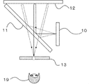
- FIG. It is explanatory drawing which shows the structure of the aerial image display device 100 of Embodiment 1.
- FIG. It is explanatory drawing which shows until the light from the image display part 10 of Embodiment 1 forms an image in the air.
- It is a block diagram which shows the structure of the display control device 15 of Embodiment 1.
- FIG. It is explanatory drawing which shows the control example in the case where the observer 19 is closer to the beam splitter 11 than the imaging range of the aerial image 13 in Embodiment 1.
- FIG. It is a block diagram which shows the structure of the display control device 15a of Embodiment 2.
- FIG. It is explanatory drawing which shows the control example in the case where the observer 19 is a position farther from the beam splitter 11 and is close to the image formation range of the aerial image 13 in Embodiment 2.
- FIG. It is explanatory drawing which shows the area 31a and area 31b in the image display part 10 of Embodiment 2.
- It is explanatory drawing which shows the area 31a, area 31b, area 31c and area 31d in the image display part 10 of Embodiment 2.
- FIG. 1 is an explanatory diagram showing the configuration of the aerial image display device 100 according to the first embodiment of the present disclosure.
- the aerial image display device 100 includes an image display unit 10, a beam splitter 11, a retroreflective sheet 12, a viewpoint position detection device 14, and a display control device 15.
- the beam splitter 11 and the retroreflective sheet 12 constitute an aerial imaging optical system that reflects diffused light emitted from the image display unit 10 a plurality of times and transmits the diffused light to reimage it in a different space.
- the image display unit 10 sends the displayed image as light to the beam splitter 11.
- the beam splitter 11 reflects the light from the image display unit 10 and sends it to the retroreflective sheet 12.
- the retroreflective sheet 12 reflects the light from the beam splitter 11 and sends it to the beam splitter 11.
- the beam splitter 11 transmits the light from the retroreflective sheet 12.
- the light transmitted through the retroreflective sheet 12 is perceived by the observer 19 as an aerial image 13.
- the viewpoint position detecting device 14 provides information on detecting the viewpoint position of the observer 19. It is sent to the display control device 15.
- the display control device 15 has a function of controlling the display light from the image display unit 10 from the information of the viewpoint position detection device 14.
- the video display unit 10 is a device in which a video input signal is input from, for example, a signal generator or a video playback device, and the displayed video is output as light.
- a display device having a liquid crystal element and a backlight such as a liquid crystal display, a display device of a self-luminous device using an organic EL element or an LED element, or a projection device using a projector and a screen. Be done.
- a display using a curved surface, a three-dimensionally arranged display, a three-dimensional display such as an LED, or a lens optical system or barrier control the observer can see both eyes.
- a display that perceives a stereoscopic image due to parallax or motion parallax may be used.
- the beam splitter 11 is an optical element that separates incident light into transmitted light and reflected light.
- the beam splitter 11 is, for example, an acrylic plate or a glass plate. Acrylic plates and glass plates generally have higher transmitted light intensity than reflected light, so even if you use an optical element that is a half mirror with metal added to the acrylic plate or glass plate to improve the reflected intensity. good.
- a reflective polarizing plate may be used in which the behavior of reflection and the behavior of transmission change depending on the polarization state of the incident light by the liquid crystal element or the thin film element.
- a reflective polarizing plate may be used in which the ratio of the transmittance and the reflectance changes depending on the polarized state of the incident light depending on the liquid crystal element or the thin film element.
- the retroreflective sheet 12 is a sheet-like optical element having retroreflective performance that reflects incident light as it is in the incident direction.
- the optical element that realizes retroreflection is a bead-type optical element in which small glass beads are laid out in a mirror surface, and a convex minute triangular pyramid or a shape in which the central part of the triangular pyramid is cut out, each surface of which is composed of a mirror surface.
- micro-prism type optical elements etc.
- FIG. 2 is an explanatory diagram showing how the light from the image display unit 10 of the first embodiment of the present disclosure forms an image in the air.
- the beam splitter 11 and the retroreflection sheet 12 are arranged in pairs with the image display unit 10.
- the light of the image from the image display unit 10 is reflected by the beam splitter 11, and this light is retroreflected by the retroreflective sheet 12, so that the solid line and the dotted line showing the optical path of the light of the image from the image display unit 10 in FIG.
- Light re-converges in the air so that and converges to one point. Since the observer 19 can visually recognize the reconverged light, it is perceived that the image exists at the position of the aerial image 13.
- the observer 19 is not limited to the structure described above as long as the structure perceives that the image exists at the position of the aerial image 13.
- a structure using a two-sided corner reflector array may be used. The light incident on one mirror surface of this structure is reflected by the other mirror surface, and the light reaches the target position with respect to this element structure. Light that is similarly reflected by a similarly diffused light source can be perceived as an aerial image by reconverging as in FIG.
- the viewpoint position detecting device 14 detects the viewpoint position.
- the viewpoint position is, for example, the position where the eyes of the observer 19 exist.
- the viewpoint position detecting device 14 is an imaging device such as a camera.
- the viewpoint position detecting device 14 detects the viewpoint position by acquiring the three-dimensional position information of the observer 19 with, for example, a compound eye camera.
- the viewpoint position detection device 14 detects the viewpoint position from three-dimensional position estimation by optical flow and feature points of the face and skeleton even in the case of a monocular camera having only a visible light region, for example.
- the viewpoint position detection device 14 detects the viewpoint position information 20 by acquiring the reflection pattern and speed of the infrared light by a camera that captures infrared light and a device that irradiates infrared light.
- the viewpoint position information 20 is, for example, information indicating the position where the eyes of the observer 19 exist. Further, the viewpoint position detecting device 14 irradiates a waveform that spreads in a three-dimensional space such as a radio wave or a magnetic field or sound as a method other than using a camera imaging element, and a device that inputs the wave acquires the irradiation waveform. There is a method of estimating the viewpoint position information 20 of a person according to the time and pattern of the operation. Further, the viewpoint position detecting device 14 acquires the viewpoint position information 20 from the position where the observer is standing by providing a pressure sensor at the foot of a place where the observer is assumed to be.
- FIG. 3 is a block diagram showing the configuration of the display control device 15.
- the display control device 15 includes an aerial imaging range estimation unit 16 and a display control processing unit 18.
- the display control device 15 receives the viewpoint position information 20 and controls the display.
- the aerial imaging range estimation unit 16 inputs the viewpoint position information 20 and the aerial imaging structure information 21, and outputs the aerial imaging range information 22 to the display control processing unit 18.
- the aerial imaging range information 22 is position information that three-dimensionally indicates the position where the aerial image is formed.
- the aerial imaging structure information 21 is information representing the positional relationship between the image display unit 10, the beam splitter 11, and the optical system members of the retroreflection sheet 12, which are necessary for forming the aerial image 13.
- the display control processing unit 18 inputs the aerial imaging range information 22 and the display video information 24, and controls the display light.
- the processing contents in each block will be described below. As a factor that lowers the image perceived by the observer 19, light other than the light forming the aerial image 13 is visually recognized.
- the aerial imaging range estimation unit 16 is composed of the viewpoint position information 20 obtained from the viewpoint position information detection unit and the aerial imaging structure information 21 having an optical arrangement structure for forming an aerial image in the aerial image display device 100. An image range of an aerial image that can be perceived by the observer 19 is estimated.
- the aerial imaging range estimation unit 16 can perform the aerial image in the display area output by the image display unit 10.
- the range perceived by the observer 19 can be estimated as.
- the viewpoint position information 20 of the observer 19 is detected and output by the viewpoint position detecting device 14. Further, the aerial imaging range information 22 is output from the aerial imaging range estimation unit 16.
- the viewpoint position of the observer 19 is closer to the beam splitter 11 than the image formation position of the aerial image 13 after the observer 19 passes through the image formation position of the aerial image 13, in other words, the observer 19 moves.
- the aerial imaging optical system and the diffused light are reimaged from the region connected to the point where the diffused light is reimaged by the aerial imaging optical system composed of the beam splitter 11 and the retroreflective sheet 12. When moving to the area between the points, it is estimated that the observer 19 will not be able to perceive the aerial image 13.
- the optical path is formed by reflecting the incident optical path once on each mirror surface. Therefore, it is presumed that the observer 19 does not perceive it as an aerial image when the reflection is performed once or less or three times or more due to the relationship between the structure and the incident angle of the light source.
- the display control processing unit 18 controls to block the optical path for forming the aerial image 13 from the aerial image formation range information 22 and the display image information 24.
- Examples of the light-shielding control method include control by turning off the image display unit 10.
- the shading control method includes control by turning off a backlight portion such as a liquid crystal display in the image display unit 10.
- control by turning off each light source of an organic EL display, an LED display, or the like in the image display unit 10 can be mentioned.
- the shading control method includes control by editing the values of all pixels of the display video information 24 to zero.
- a light-shielding control method for example, an optical film or a physical light-shielding device may be used.
- the light-shielding device is installed on the optical path until the light emitted by the image display unit 10 reaches the observer 19 as an aerial image 13, and the light-shielding device can be controlled by an electronic shutter or a curtain. Further, as a shading control method, for example, the value of all pixels of the video input signal may be changed to zero and supplied to the video display unit 10.
- FIG. 4 is an explanatory diagram showing a control example when the observer 19 is closer to the beam splitter 11 than the position of the aerial image 13. Since the optical path before forming an image on the aerial image 13 is visually recognized, as a control, the area of the light visually recognized by the observer 19 is shaded as the display shading area 31, so that the image light which becomes unpleasant light is visually recognized. Eliminate the discomfort caused by this.
- aerial image display device configured in this way, light that is visually unpleasant for the observer is generated by blocking the optical path that forms the image of the aerial image 13 from the result of estimating the deterioration of the image quality of the aerial image 13. Only aerial images can be perceived with appropriate display quality without being visually recognized.
- Embodiment 2 In the present embodiment, an image quality conversion process for estimating the image quality of the aerial image 13 visually recognized by the observer 19 and controlling the display image quality will be described.
- FIG. 5 is a block diagram showing the configuration of the display control device 15a.
- the display control device 15a includes an aerial imaging range estimation unit 16, an aerial image visual estimation unit 17, and a display control processing unit 18a.
- the display control device 15a receives the viewpoint position information 20, the aerial imaging structure information 21, and the display video information 24, and controls the display.
- the aerial imaging range estimation unit 16 is input with the viewpoint position information 20 and the aerial imaging structure information 21, and outputs the aerial imaging range information 22 to the aerial image visual estimation unit 17.
- the aerial image visual estimation unit 17 receives the aerial imaging range information 22 and outputs the aerial image quality estimation information 23 to the display control processing unit 18a.
- the aerial image quality estimation information 23 is information representing the image quality of the aerial image 13 visually observed by the observer. For example, it indicates a luminance value indicating the brightness when displaying white luminance, information indicating a contrast ratio when displaying white luminance and black luminance adjacent to each other, and chromaticity when displaying a color such as RGB. Information etc. can be mentioned.
- the display control processing unit 18a inputs the aerial image quality estimation information 23 and the display image information 24, and controls the display light. The processing contents in each block will be described below.
- the display video information 24 is input from, for example, a signal generator.
- the aerial image visual estimation unit 17 estimates the image quality of the aerial image 13 visually recognized by the observer 19 in a range that can be perceived as an aerial image obtained by the aerial imaging range estimation unit 16.
- the optical path connecting the positional relationships of both eyes is estimated for each pixel at the combined position of the aerial image.
- a three-dimensional straight line connecting the target aerial image pixel and the right eye and a three-dimensional straight line connecting the target aerial image pixel and the left eye are calculated, and the respective angles at which these straight lines and the retroreflective sheet 12 intersect. Is calculated.
- the image quality of the image due to the light visually recognized by each eye changes depending on the constituent optical system members and the position of the observer.
- the image quality of each pixel of the image due to the light visually recognized by the right eye and the left eye is estimated and mapped as a parameter.
- the image quality referred to in the present embodiment is the image quality perceived by the observer 19, and includes the brightness, sharpness, or chromaticity of the aerial image 13 perceived by the observer 19.
- the angle formed by the straight line connecting the end points of the retroreflective sheet 12 and the eye and the straight line reaching the retroreflective sheet 12 in front of the eye becomes large, that is, when the observer 19 is too close to the imaging position of the aerial image 13.
- the brightness and sharpness of the aerial image 13 perceived by the observer 19 change.
- a film material or a polarizing film whose wavelength changes optically is used on the surface of the beam splitter 11 or the retroreflective sheet 12
- the light incident angle perceived by the observer 19 as an aerial image 13 is increased. Diffraction, changes in wavelength due to polarized light, changes in reflection transmittance, and the like occur, and the brightness and chromaticity of the perceived aerial image 13 change.
- the beam splitter 11 when a material having a large plate thickness has the same reflectance and transmittance on both sides, reflection and transmission when forming the aerial image 13 are executed on both sides, and imaging is performed. Two aerial images 13 having different ranges may be formed. In that case, the light for perceiving the aerial image 13 is double-recognized, and the sharpness of the aerial image is lowered. Further, by performing specular reflection instead of retroreflection on the surface of the retroreflective sheet 12, a mirror image may be visually recognized in the back of the retroreflective sheet 12. When this mirror image interferes with the aerial image 13, the image quality of the aerial image 13 perceived by the observer 19 is deteriorated.
- FIG. 6 is an explanatory diagram showing a control example when the observer 19 is farther from the beam splitter 11 than the imaging range of the aerial image 13 and is close to the imaging range of the aerial image 13. Since the image displayed by the image display unit 10 is formed into an aerial image 13, the visual area and the light-shielding area or the control area of each eye will be described with reference to the display range of the image display unit. The larger the angle formed by the straight line connecting the left end point of the retroreflective sheet 12 and the left eye and the straight line reaching the front retroreflective sheet 12 from the left eye, the sharper the image due to the light visually recognized by the observer 19 34. Decreases.
- the sharpness 34 in the visual region 32 of the left eye decreases on the left side with respect to the vicinity of the center.
- the visual region 32 of the left eye whose sharpness 34 is equal to or less than the set threshold value is defined as the region 32a.
- the threshold value is set based on the perceptible contrast ratio and brightness based on human visual characteristics.
- Degree 34 decreases as well. Specifically, the sharpness 34 in the visual region 32 of the left eye decreases on the right side with respect to the vicinity of the center.
- the visual region 32 of the left eye whose sharpness 34 is equal to or less than the set threshold value is defined as the region 32b.
- Degree 35 drops.
- the sharpness 35 in the visual region 33 of the right eye decreases on the left side with respect to the vicinity of the center.
- the visual region 33 of the left eye below the threshold value at which the sharpness 35 is set is defined as the region 33a.
- Sharpness 35 is reduced. Specifically, the sharpness 35 in the visual region 33 of the right eye decreases on the right side with respect to the vicinity of the center.
- the visual region 33 of the right eye whose sharpness 35 is equal to or less than the set threshold value is defined as the region 33b.
- region 32a, region 32b, region 33a, and region 33b In regions where the sharpness is reduced, such as region 32a, region 32b, region 33a, and region 33b, it becomes difficult for the observer 19 to perceive that each eye is visually recognizing the same pixel, and the positional relationship of the aerial image 13 Can't perceive and feels unpleasant light. Therefore, it is desirable to block the pixels in the portion where the image quality perceived by the observer 19 is significantly different. Specifically, among the combined regions of the left eye visual region 32 and the right eye visual region 33, the region 31a of the region 32a or the region 33a and the region 31b of the region 32b or the region 33b are controlled to block light. Perform the operation.
- FIG. 7 is an explanatory diagram showing a region 31a and a region 31b in the video display unit 10.
- the shading range is determined inside the visual area 32 of the left eye and the visual area 33 of the right eye, but the visual area 32 of the left eye and the visual area 33 of the right eye in the image display unit 10 are determined.
- the area 31a and the area 31b may be extended to the outside of the area to extend the shading range.
- FIG. 8 is an explanatory diagram showing a region 31a, a region 31b, a region 31c, and a region 31d in the video display unit 10.
- the area on the left side of the area 31a is defined as the area 31c.
- the area on the right side of the area 31b is defined as the area 31d.
- the area that is perceived as unpleasant light for the observer 19 is controlled to be shielded from light.
- the display image information 24 is subjected to a filter process for reducing the brightness and sharpness in the areas 31a and 31b. Therefore, changes in image quality perceived by each eye, such as blurring, changes in brightness, or changes in contrast, may be made difficult to see, and light may be blocked in the regions 31c and 31d.
- the display control processing unit 18a controls to change the image quality of the aerial image 13 from the aerial image image quality estimation information 23.
- the image quality control method for the aerial image 13 include a control method using an optical filter for the image light source. For example, by arranging a diffusion film or a retardation film and mechanically controlling the installation position and angle thereof, it is possible to locally change the brightness and resolution of the aerial image 13.
- an image quality control method of the aerial image 13 it is also possible to control the display image quality by performing a filter process or a color conversion process on the display image information 24 input to the image display unit 10. In the filter processing, it is possible to control the sharpness and the sense of resolution by the filter for each frequency domain of the input display image information 24.
- the image quality control method may be, for example, a method of performing filter processing or color conversion processing on the video input signal and supplying the video input signal to the video display unit 10.
- the aerial image display device configured as described above, when the observer is located at a position far from the beam splitter 11 from the imaging range of the aerial image 13 and near the imaging range of the aerial image 13, the reflection is performed. Even if the angle formed by the straight line connecting the end points of the reflective sheet 12 and the eye and the straight line reaching the retroreflective sheet 12 in front of the eye becomes large, the aerial image can be properly perceived.
- Image display unit 11 Beam splitter 12 Retroreflective sheet 13 Aerial image 14 Viewpoint position detection device 15
- Display control device 16
- Aerial imaging range estimation unit 17 Aerial image visual estimation unit 18
- Display control processing unit 19 Observer 20
- Viewpoint position information 21 Aerial Imaging structure information 22
- Aerial imaging range information 23 Aerial image image quality estimation information 24
- Displayed image information 31 Display shading area 32 Left eye visual area 33 Right eye visual area 100
Abstract
This aerial video display device (100) is characterized by comprising: a video display unit (10) that displays a video; an aerial image-forming optical system that causes diffused light emitted from the video display unit to be re-formed on different spaces by reflecting and transmitting the diffused light a number of times; a viewpoint position detecting device (14) that acquires information pertaining to a viewpoint position of a viewer looking at a point where the diffused light is re-formed by the aerial image-forming optical system; and a display control processing unit (18) that controls the video from the video display unit (10) at the time when the position of a viewer is detected who moves from a region, in front of the position where the points re-formed by the aerial image-forming optical system are joined, to a region between the aerial image-forming optical system and the re-formed points.
Description
本開示は、表示素子のない空中に映像を映し出す空中映像表示装置に関する。
The present disclosure relates to an aerial image display device that displays an image in the air without a display element.
表示素子のない空中映像を映し出す、空中映像結像技術を使用した表示装置において表示される映像を観察者に応じて調整するシステムが存在する。例えば特許文献1では空中映像に対して観察者の視点位置に応じて表示の有無を制御することで、観察者が表示装置からの光を視認することができる位置にいた場合に観察者が空中映像を知覚することを可能としている。
There is a system that adjusts the image displayed on a display device that uses aerial image imaging technology to project an aerial image without a display element according to the observer. For example, in Patent Document 1, by controlling the presence or absence of display of an aerial image according to the viewpoint position of the observer, the observer is in the air when the observer is in a position where the light from the display device can be visually recognized. It makes it possible to perceive images.
観察者が通過する動線上の空間に空中映像を投影する配置構造にした場合、観察者が知覚する空中映像の結像位置を通過した直後に、映像にならない不必要な光である、映像を空間に結像する前の光が観察者に視認されるという問題があった。
When the arrangement structure is such that the aerial image is projected onto the space on the movement line through which the observer passes, the image, which is unnecessary light that does not become an image immediately after passing the imaging position of the aerial image perceived by the observer, is displayed. There is a problem that the light before the image is formed in the space is visually recognized by the observer.
本開示は上述のような課題を解決するためになされたもので、観察者に映像を空間に結像する前の光が視認されることなく空中映像を適切な表示品位で知覚させることを可能とするものである。
The present disclosure has been made to solve the above-mentioned problems, and it is possible for an observer to perceive an aerial image with an appropriate display quality without visually recognizing the light before forming the image in space. Is to be.
本開示は、映像を表示する映像表示部と、映像表示部から発する拡散光を複数回反射させ、かつ透過することで異なる空間上に再結像させる空中結像光学系と、空中結像光学系により拡散光が再結像される地点を見る観察者の視点位置情報を取得する視点位置情報取得部と、空中結像光学系と再結像される地点との間の領域に観察者が存在することを検知した時に映像表示部からの拡散光を遮光する表示制御処理部とを備えることを特徴とする。
The present disclosure discloses an image display unit that displays an image, an aerial imaging optical system that reflects diffused light emitted from the image display unit a plurality of times and transmits the diffused light to reimage the image in different spaces, and aerial imaging optics. The observer is in the area between the viewpoint position information acquisition unit that acquires the viewpoint position information of the observer who sees the point where the diffused light is reimaged by the system, and the aerial imaging optical system and the point where the diffused light is reimaged. It is characterized by including a display control processing unit that blocks diffused light from the image display unit when it is detected to be present.
本開示により、空中結像を成す空中映像表示装置において、観察者が通過する動線上の空間に空中映像を投影する配置構造において、観察者が空中映像を通過した直後にいる場合でも、空中結像光学系から再結像される地点までの領域に移動する観察者位置を検知した時に映像表示部からの映像を遮光することにより、視野に映像を空間に結像する前の光が視認されない空中映像表示装置を実現できる。
According to the present disclosure, in an aerial image display device that forms an aerial image, in an arrangement structure that projects an aerial image into a space on a movement line through which an observer passes, even if the observer is immediately after passing through the aerial image, the aerial connection is established. By blocking the image from the image display unit when the observer position moving to the area from the image optical system to the point to be reimaged is detected, the light before the image is imaged in space is not visible in the field of view. An aerial image display device can be realized.
以下、本開示の実施の形態を図面に従って説明する。
実施の形態1
図1は、本開示の実施の形態1の空中映像表示装置100の構成を示す説明図である。図1において、空中映像表示装置100は、映像表示部10、ビームスプリッタ11、再帰反射シート12、視点位置検出装置14、及び表示制御装置15を備える。また、ビームスプリッタ11及び再帰反射シート12は、映像表示部10から発する拡散光を複数回反射させ、かつ透過することで異なる空間上に再結像させる空中結像光学系を構成する。映像表示部10は、表示した映像を光としてビームスプリッタ11に送る。ビームスプリッタ11が映像表示部10からの光を反射して、再帰反射シート12に送る。再帰反射シート12は、ビームスプリッタ11からの光を反射して、ビームスプリッタ11に送る。ビームスプリッタ11は、再帰反射シート12からの光を透過する。再帰反射シート12を透過した光は観察者19に空中映像13として知覚される。視点位置検出装置14は、観察者19の視点位置を検出した情報を。表示制御装置15に送る。表示制御装置15は、視点位置検出装置14の情報から映像表示部10からの表示光を制御する機能を有する。 Hereinafter, embodiments of the present disclosure will be described with reference to the drawings.
Embodiment 1
FIG. 1 is an explanatory diagram showing the configuration of the aerialimage display device 100 according to the first embodiment of the present disclosure. In FIG. 1, the aerial image display device 100 includes an image display unit 10, a beam splitter 11, a retroreflective sheet 12, a viewpoint position detection device 14, and a display control device 15. Further, the beam splitter 11 and the retroreflective sheet 12 constitute an aerial imaging optical system that reflects diffused light emitted from the image display unit 10 a plurality of times and transmits the diffused light to reimage it in a different space. The image display unit 10 sends the displayed image as light to the beam splitter 11. The beam splitter 11 reflects the light from the image display unit 10 and sends it to the retroreflective sheet 12. The retroreflective sheet 12 reflects the light from the beam splitter 11 and sends it to the beam splitter 11. The beam splitter 11 transmits the light from the retroreflective sheet 12. The light transmitted through the retroreflective sheet 12 is perceived by the observer 19 as an aerial image 13. The viewpoint position detecting device 14 provides information on detecting the viewpoint position of the observer 19. It is sent to the display control device 15. The display control device 15 has a function of controlling the display light from the image display unit 10 from the information of the viewpoint position detection device 14.
実施の形態1
図1は、本開示の実施の形態1の空中映像表示装置100の構成を示す説明図である。図1において、空中映像表示装置100は、映像表示部10、ビームスプリッタ11、再帰反射シート12、視点位置検出装置14、及び表示制御装置15を備える。また、ビームスプリッタ11及び再帰反射シート12は、映像表示部10から発する拡散光を複数回反射させ、かつ透過することで異なる空間上に再結像させる空中結像光学系を構成する。映像表示部10は、表示した映像を光としてビームスプリッタ11に送る。ビームスプリッタ11が映像表示部10からの光を反射して、再帰反射シート12に送る。再帰反射シート12は、ビームスプリッタ11からの光を反射して、ビームスプリッタ11に送る。ビームスプリッタ11は、再帰反射シート12からの光を透過する。再帰反射シート12を透過した光は観察者19に空中映像13として知覚される。視点位置検出装置14は、観察者19の視点位置を検出した情報を。表示制御装置15に送る。表示制御装置15は、視点位置検出装置14の情報から映像表示部10からの表示光を制御する機能を有する。 Hereinafter, embodiments of the present disclosure will be described with reference to the drawings.
Embodiment 1
FIG. 1 is an explanatory diagram showing the configuration of the aerial
映像表示部10は、例えば信号発生器や映像再生装置などから映像入力信号が入力され、表示する映像を光として出力する装置である。これは、例えば液晶ディスプレイのような液晶素子とバックライトとを備えた表示装置、有機EL素子やLED素子を用いた自発光デバイスの表示装置、又は、プロジェクタとスクリーンとを用いた投影装置が挙げられる。また前記のような2次元平面光源だけではなく、曲面を用いたディスプレイ、立体的に配置したディスプレイ、LED等の立体表示ディスプレイ、又はレンズ光学系やバリア制御を利用することにより観察者に両眼視差や運動視差による立体映像を知覚させるディスプレイを用いてもよい。
The video display unit 10 is a device in which a video input signal is input from, for example, a signal generator or a video playback device, and the displayed video is output as light. This includes, for example, a display device having a liquid crystal element and a backlight such as a liquid crystal display, a display device of a self-luminous device using an organic EL element or an LED element, or a projection device using a projector and a screen. Be done. Further, by using not only the two-dimensional plane light source as described above, but also a display using a curved surface, a three-dimensionally arranged display, a three-dimensional display such as an LED, or a lens optical system or barrier control, the observer can see both eyes. A display that perceives a stereoscopic image due to parallax or motion parallax may be used.
ビームスプリッタ11は、入射する光を透過光と反射光とに分離する光学素子である。ビームスプリッタ11は例えばアクリル板やガラス板である。アクリル板やガラス板は一般的に反射光に比べ透過光の強度が高いことから、アクリル板やガラス板に金属を付加して反射強度を向上させたハーフミラーとした光学素子を利用してもよい。また、液晶素子や薄膜素子による入射光の偏光状態により、反射の振舞いと透過の振舞いとが変化する反射型偏光板を利用してもよい。また液晶素子や薄膜素子により入射光の偏光状態で透過率と反射率との割合が変化する反射型偏光板を利用してもよい。
The beam splitter 11 is an optical element that separates incident light into transmitted light and reflected light. The beam splitter 11 is, for example, an acrylic plate or a glass plate. Acrylic plates and glass plates generally have higher transmitted light intensity than reflected light, so even if you use an optical element that is a half mirror with metal added to the acrylic plate or glass plate to improve the reflected intensity. good. Further, a reflective polarizing plate may be used in which the behavior of reflection and the behavior of transmission change depending on the polarization state of the incident light by the liquid crystal element or the thin film element. Further, a reflective polarizing plate may be used in which the ratio of the transmittance and the reflectance changes depending on the polarized state of the incident light depending on the liquid crystal element or the thin film element.
再帰反射シート12は、入射した光を入射した方向にそのまま反射する再帰反射性能を持つシート状の光学素子である。再帰反射を実現する光学素子には、鏡面状に小さなガラスビーズを敷き詰めたビーズタイプの光学素子、各面が鏡面で構成される凸形状の微小の三角錐または三角錐の中心部を切り取った形状を敷き詰めたマイクロプリズムタイプの光学素子などがある。
The retroreflective sheet 12 is a sheet-like optical element having retroreflective performance that reflects incident light as it is in the incident direction. The optical element that realizes retroreflection is a bead-type optical element in which small glass beads are laid out in a mirror surface, and a convex minute triangular pyramid or a shape in which the central part of the triangular pyramid is cut out, each surface of which is composed of a mirror surface. There are micro-prism type optical elements, etc.
図2は、本開示の実施の形態1の映像表示部10からの光が空中に映像を結像するまでを示す説明図である。本実施の形態の空中映像表示装置は、映像表示部10と対にしてビームスプリッタ11と再帰反射シート12とを配置する。映像表示部10からの映像の光がビームスプリッタ11で反射され、この光が再帰反射シート12で再帰反射することにより、図2における映像表示部10からの映像の光の光路を示す実線と点線とが一点に収束するように、光が空中に再収束する。観察者19には再収束した光が視認できるため空中映像13の位置に映像が存在すると知覚される。
FIG. 2 is an explanatory diagram showing how the light from the image display unit 10 of the first embodiment of the present disclosure forms an image in the air. In the aerial image display device of the present embodiment, the beam splitter 11 and the retroreflection sheet 12 are arranged in pairs with the image display unit 10. The light of the image from the image display unit 10 is reflected by the beam splitter 11, and this light is retroreflected by the retroreflective sheet 12, so that the solid line and the dotted line showing the optical path of the light of the image from the image display unit 10 in FIG. Light re-converges in the air so that and converges to one point. Since the observer 19 can visually recognize the reconverged light, it is perceived that the image exists at the position of the aerial image 13.
また、観察者19は、空中映像13の位置に映像が存在すると知覚する構造であれば、上記で説明した構造に限るものではない。例えば、ビームスプリッタ11、再帰反射シート12を、直交した2面の鏡面を重ね合わせて平面上にアレイ状の配置をした構造や、樹脂製の構造において内部反射を用いて前記鏡面を実現する構造など、2面コーナーリフレクタアレイ(dihedral corner reflector array)を利用した構造でもよい。この構造の片方の鏡面方向に対して入射した光はもう片方の鏡面に反射しつつ、この素子構造に対して対象の位置へと光が到達する。同様に拡散する光源において同様の反射を行う光は図1と同様に再収束することで、空中映像を知覚することができる。
Further, the observer 19 is not limited to the structure described above as long as the structure perceives that the image exists at the position of the aerial image 13. For example, a structure in which the beam splitter 11 and the retroreflective sheet 12 are arranged in an array on a plane by superimposing two orthogonal mirror surfaces, or a structure in which the mirror surface is realized by using internal reflection in a resin structure. For example, a structure using a two-sided corner reflector array may be used. The light incident on one mirror surface of this structure is reflected by the other mirror surface, and the light reaches the target position with respect to this element structure. Light that is similarly reflected by a similarly diffused light source can be perceived as an aerial image by reconverging as in FIG.
視点位置検出装置14は、視点位置を検出する。視点位置は、例えば、観察者19の眼が存在する位置である。視点位置検出装置14は、例えばカメラなどの撮像デバイスである。視点位置検出装置14は、例えば複眼カメラにより観察者19の三次元的な位置情報を取得することにより、視点位置を検出する。視点位置検出装置14は、例えば可視光領域のみの単眼カメラである場合でもオプティカルフローによる三次元位置推定や顔や骨格の特徴点から視点位置を検出する。視点位置検出装置14は、赤外光を撮像するカメラと赤外線を照射する装置とにより、その赤外光の反射パターンや速度を取得することで、視点位置情報20を検出する。視点位置情報20とは、例えば、観察者19の眼が存在する位置を示す情報である。また、視点位置検出装置14は、カメラ撮像素子を用いる以外の方法として、電波、または、磁場や音などの三次元空間を波及する波形を照射し、その波を入力する機器が照射波形を取得する時間やパターンに応じて人の視点位置情報20を推定する方法がある。また、視点位置検出装置14は、観察者がいると想定される場所の足元に感圧センサを設けることで、観察者の立っている位置から視点位置情報20を取得する。
The viewpoint position detecting device 14 detects the viewpoint position. The viewpoint position is, for example, the position where the eyes of the observer 19 exist. The viewpoint position detecting device 14 is an imaging device such as a camera. The viewpoint position detecting device 14 detects the viewpoint position by acquiring the three-dimensional position information of the observer 19 with, for example, a compound eye camera. The viewpoint position detection device 14 detects the viewpoint position from three-dimensional position estimation by optical flow and feature points of the face and skeleton even in the case of a monocular camera having only a visible light region, for example. The viewpoint position detection device 14 detects the viewpoint position information 20 by acquiring the reflection pattern and speed of the infrared light by a camera that captures infrared light and a device that irradiates infrared light. The viewpoint position information 20 is, for example, information indicating the position where the eyes of the observer 19 exist. Further, the viewpoint position detecting device 14 irradiates a waveform that spreads in a three-dimensional space such as a radio wave or a magnetic field or sound as a method other than using a camera imaging element, and a device that inputs the wave acquires the irradiation waveform. There is a method of estimating the viewpoint position information 20 of a person according to the time and pattern of the operation. Further, the viewpoint position detecting device 14 acquires the viewpoint position information 20 from the position where the observer is standing by providing a pressure sensor at the foot of a place where the observer is assumed to be.
図3は、表示制御装置15の構成を示すブロック図である。表示制御装置15は、空中結像範囲推定部16、及び表示制御処理部18を備える。表示制御装置15は、視点位置情報20が入力され、表示制御を行う。空中結像範囲推定部16は、視点位置情報20と空中結像構造情報21とが入力され、空中結像範囲情報22を表示制御処理部18に出力する。空中結像範囲情報22は、空中映像が結像する位置を三次元的に示す位置情報である。空中結像構造情報21とは、空中映像13を形成するために必要となる映像表示部10、ビームスプリッタ11、及び再帰反射シート12の光学系部材の位置関係を表す情報である。例えば、各部材の三次元CAD情報であり、各部材の三次元空間の配置位置・形状を表したものである。表示制御処理部18は、空中結像範囲情報22と表示映像情報24とが入力され、表示光の制御を行う。各ブロックにおける処理内容について以下に説明する。観察者19が知覚する画像を低下させる要因として、空中映像13を形成する光以外の光が視認されることが挙げられる。
FIG. 3 is a block diagram showing the configuration of the display control device 15. The display control device 15 includes an aerial imaging range estimation unit 16 and a display control processing unit 18. The display control device 15 receives the viewpoint position information 20 and controls the display. The aerial imaging range estimation unit 16 inputs the viewpoint position information 20 and the aerial imaging structure information 21, and outputs the aerial imaging range information 22 to the display control processing unit 18. The aerial imaging range information 22 is position information that three-dimensionally indicates the position where the aerial image is formed. The aerial imaging structure information 21 is information representing the positional relationship between the image display unit 10, the beam splitter 11, and the optical system members of the retroreflection sheet 12, which are necessary for forming the aerial image 13. For example, it is three-dimensional CAD information of each member, and represents the arrangement position and shape of each member in the three-dimensional space. The display control processing unit 18 inputs the aerial imaging range information 22 and the display video information 24, and controls the display light. The processing contents in each block will be described below. As a factor that lowers the image perceived by the observer 19, light other than the light forming the aerial image 13 is visually recognized.
空中結像範囲推定部16は、視点位置情報検出部から得られた視点位置情報20と空中映像表示装置100における空中映像の結像する光学的な配置構造を持つ空中結像構造情報21とから観察者19が知覚することができる空中映像の結像する範囲を推定する。
The aerial imaging range estimation unit 16 is composed of the viewpoint position information 20 obtained from the viewpoint position information detection unit and the aerial imaging structure information 21 having an optical arrangement structure for forming an aerial image in the aerial image display device 100. An image range of an aerial image that can be perceived by the observer 19 is estimated.
例えば、再帰反射を利用した空中結像構造では、観察者19から空中映像13の方向を見た際に、視線上にビームスプリッタ11が存在し、更にビームスプリッタ11から透過した線上又は反射した線上に再帰反射シート12が存在している場合に空中映像13を知覚することができる。つまり、視点位置情報20と空中結像構造情報21との両情報から三次元光路追跡を行うことで、空中結像範囲推定部16は、映像表示部10が出力する表示領域のうち、空中映像として観察者19が知覚する範囲を推定することができる。
For example, in the aerial imaging structure using retroreflection, when the observer 19 looks at the direction of the aerial image 13, the beam splitter 11 is present on the line of sight, and further on the line transmitted or reflected from the beam splitter 11. The aerial image 13 can be perceived when the retroreflective sheet 12 is present in. That is, by performing the three-dimensional optical path tracking from both the viewpoint position information 20 and the aerial imaging structure information 21, the aerial imaging range estimation unit 16 can perform the aerial image in the display area output by the image display unit 10. The range perceived by the observer 19 can be estimated as.
上記説明の通り、観察者19の視点位置情報20は、視点位置検出装置14により検出され出力される。また、空中結像範囲情報22は、空中結像範囲推定部16より出力される。観察者19の視点位置が、観察者19が空中映像13の結像位置を通り抜けて、空中映像13の結像位置よりビームスプリッタ11に近い位置にある場合、言いかえると、観察者19が、ビームスプリッタ11及び再帰反射シート12から構成される空中結像光学系によって拡散光が再結像される地点を結んだ先にある領域から、空中結像光学系と拡散光が再結像される地点との間の領域に移動した場合、観察者19は空中映像13を知覚することができない状態になると推定される。
As described above, the viewpoint position information 20 of the observer 19 is detected and output by the viewpoint position detecting device 14. Further, the aerial imaging range information 22 is output from the aerial imaging range estimation unit 16. When the viewpoint position of the observer 19 is closer to the beam splitter 11 than the image formation position of the aerial image 13 after the observer 19 passes through the image formation position of the aerial image 13, in other words, the observer 19 moves. The aerial imaging optical system and the diffused light are reimaged from the region connected to the point where the diffused light is reimaged by the aerial imaging optical system composed of the beam splitter 11 and the retroreflective sheet 12. When moving to the area between the points, it is estimated that the observer 19 will not be able to perceive the aerial image 13.
前述した2面コーナーリフレクタアレイ構造においても空中映像13の結像位置を推定することが可能となる。2面コーナーリフレクタアレイ構造の場合には、入射する光路がそれぞれの鏡面に1回ずつ反射することで光路が結像される。そのため、構造と光源との入射角度との関係性により、1回以下や3回以上の反射を行う場合には観察者19に空中映像として知覚されないことが推定される。
Even in the two-sided corner reflector array structure described above, it is possible to estimate the imaging position of the aerial image 13. In the case of the two-sided corner reflector array structure, the optical path is formed by reflecting the incident optical path once on each mirror surface. Therefore, it is presumed that the observer 19 does not perceive it as an aerial image when the reflection is performed once or less or three times or more due to the relationship between the structure and the incident angle of the light source.
表示制御処理部18は、空中結像範囲情報22と表示映像情報24とから空中映像13を結像する光路を遮光する制御を行う。遮光制御方法は、例えば、映像表示部10を消灯することによる制御が挙げられる。または、遮光制御方法は、映像表示部10において液晶ディスプレイなどのバックライト部分を消灯することによる制御が挙げられる。または、遮光制御方法は、映像表示部10において有機ELディスプレイやLEDディスプレイなどは各光源を消灯することによる制御が挙げられる。または、遮光制御方法は、表示映像情報24の全画素の値を零に編集することによる制御が挙げられる。また遮光制御方法は例えば、光学フィルムや物理的な遮光装置を利用することが挙げられる。遮光装置は映像表示部10が発光した光が観察者19まで空中映像13として届くまでの光路上に設置され、電子シャッターやカーテンによる遮光制御が可能となる。また遮光制御方法は例えば、映像入力信号の全画素の値を零に変更して映像表示部10に供給することが挙げられる。
The display control processing unit 18 controls to block the optical path for forming the aerial image 13 from the aerial image formation range information 22 and the display image information 24. Examples of the light-shielding control method include control by turning off the image display unit 10. Alternatively, the shading control method includes control by turning off a backlight portion such as a liquid crystal display in the image display unit 10. Alternatively, as a shading control method, control by turning off each light source of an organic EL display, an LED display, or the like in the image display unit 10 can be mentioned. Alternatively, the shading control method includes control by editing the values of all pixels of the display video information 24 to zero. Further, as a light-shielding control method, for example, an optical film or a physical light-shielding device may be used. The light-shielding device is installed on the optical path until the light emitted by the image display unit 10 reaches the observer 19 as an aerial image 13, and the light-shielding device can be controlled by an electronic shutter or a curtain. Further, as a shading control method, for example, the value of all pixels of the video input signal may be changed to zero and supplied to the video display unit 10.
図4は、空中映像13の位置より観察者19がビームスプリッタ11に近い位置にいる場合の制御例を示す説明図である。空中映像13に結像する前の光路を視認してしまうため、制御としては観察者19が視認する光の領域を表示遮光領域31として遮光することで、不快な光となる映像光を視認することによる不快感をなくす。
FIG. 4 is an explanatory diagram showing a control example when the observer 19 is closer to the beam splitter 11 than the position of the aerial image 13. Since the optical path before forming an image on the aerial image 13 is visually recognized, as a control, the area of the light visually recognized by the observer 19 is shaded as the display shading area 31, so that the image light which becomes unpleasant light is visually recognized. Eliminate the discomfort caused by this.
このように構成された空中映像表示装置においては、空中映像13の画質の低下を推定した結果から空中映像13を結像する光路を遮光することにより、観察者にとって視覚的に不快となる光が視認されることなく空中映像のみを適切な表示品位で知覚することができる。
In the aerial image display device configured in this way, light that is visually unpleasant for the observer is generated by blocking the optical path that forms the image of the aerial image 13 from the result of estimating the deterioration of the image quality of the aerial image 13. Only aerial images can be perceived with appropriate display quality without being visually recognized.
実施の形態2
本実施の形態では、観察者19が視認する空中映像13の画質を推定して表示画質を制御する画質変換処理について説明する。 Embodiment 2
In the present embodiment, an image quality conversion process for estimating the image quality of theaerial image 13 visually recognized by the observer 19 and controlling the display image quality will be described.
本実施の形態では、観察者19が視認する空中映像13の画質を推定して表示画質を制御する画質変換処理について説明する。 Embodiment 2
In the present embodiment, an image quality conversion process for estimating the image quality of the
図5は、表示制御装置15aの構成を示すブロック図である。本実施の形態では、実施の形態1における表示制御装置15を表示制御装置15aに置き換えるが、それ以外の構成は、実施の形態1と同じである。表示制御装置15aは、空中結像範囲推定部16、空中映像視覚推定部17、及び表示制御処理部18aを備える。表示制御装置15aは、視点位置情報20、空中結像構造情報21、及び表示映像情報24が入力され、表示制御を行う。空中結像範囲推定部16は、視点位置情報20及び空中結像構造情報21が入力され、空中結像範囲情報22を空中映像視覚推定部17に出力する。空中映像視覚推定部17は、空中結像範囲情報22が入力され、空中映像画質推定情報23を表示制御処理部18aに出力する。空中映像画質推定情報23は、観察者が視覚する空中映像13の映像品位を表す情報である。例えば、白輝度を表示した際の明るさを表す輝度値や、白輝度と黒輝度を隣接して表示した際のコントラスト比を示す情報や、RGBなどの色を表示した際の色度を示す情報などが挙げられる。表示制御処理部18aは、空中映像画質推定情報23及び表示映像情報24が入力され、表示光の制御を行う。各ブロックにおける処理内容について以下に説明する。表示映像情報24は、例えば信号発生器などから入力される。
FIG. 5 is a block diagram showing the configuration of the display control device 15a. In the present embodiment, the display control device 15 in the first embodiment is replaced with the display control device 15a, but the other configurations are the same as those in the first embodiment. The display control device 15a includes an aerial imaging range estimation unit 16, an aerial image visual estimation unit 17, and a display control processing unit 18a. The display control device 15a receives the viewpoint position information 20, the aerial imaging structure information 21, and the display video information 24, and controls the display. The aerial imaging range estimation unit 16 is input with the viewpoint position information 20 and the aerial imaging structure information 21, and outputs the aerial imaging range information 22 to the aerial image visual estimation unit 17. The aerial image visual estimation unit 17 receives the aerial imaging range information 22 and outputs the aerial image quality estimation information 23 to the display control processing unit 18a. The aerial image quality estimation information 23 is information representing the image quality of the aerial image 13 visually observed by the observer. For example, it indicates a luminance value indicating the brightness when displaying white luminance, information indicating a contrast ratio when displaying white luminance and black luminance adjacent to each other, and chromaticity when displaying a color such as RGB. Information etc. can be mentioned. The display control processing unit 18a inputs the aerial image quality estimation information 23 and the display image information 24, and controls the display light. The processing contents in each block will be described below. The display video information 24 is input from, for example, a signal generator.
空中映像視覚推定部17は、空中結像範囲推定部16により得られた空中映像として知覚することができる範囲における、観察者19に視認される空中映像13の画質を推定する。
The aerial image visual estimation unit 17 estimates the image quality of the aerial image 13 visually recognized by the observer 19 in a range that can be perceived as an aerial image obtained by the aerial imaging range estimation unit 16.
以下、空中映像視覚推定部17における左右の眼の画質推定方法について詳細に記載する。まず空中映像の結合位置での各画素に対して、両眼の位置関係を結ぶ光路を推定する。対象の空中映像画素と右眼とが結ぶ三次元直線、及び対象の空中映像画素と左眼とが結ぶ三次元直線とを算出し、これらの直線と再帰反射シート12とが交差するそれぞれの角度を算出する。
Hereinafter, the image quality estimation method for the left and right eyes in the aerial video visual estimation unit 17 will be described in detail. First, the optical path connecting the positional relationships of both eyes is estimated for each pixel at the combined position of the aerial image. A three-dimensional straight line connecting the target aerial image pixel and the right eye and a three-dimensional straight line connecting the target aerial image pixel and the left eye are calculated, and the respective angles at which these straight lines and the retroreflective sheet 12 intersect. Is calculated.
再帰反射を利用した空中映像結像構造は、構成される光学系部材及び観察者位置によって各眼が視認する光による映像の画質が変化する。本実施の形態では、観察者19が知覚する空中映像13において、右眼と左眼とがそれぞれ視認する光による映像の各画素の画質を推定しパラメータとしてマッピングする。本実施の形態でいう画質とは、観察者19が知覚する画質であって、観察者19が知覚する空中映像13の明るさ、先鋭さ、又は色度が挙げられる。再帰反射シート12の端点及び眼を結ぶ直線と、眼から正面の再帰反射シート12に到達する直線とがなす角が、大きくなる、つまり観察者19が空中映像13の結像位置に近すぎると、観察者19が知覚する空中映像13の明るさや先鋭さが変化する。例えば、ビームスプリッタ11や再帰反射シート12の表面に光学的に波長変化するフィルム素材や偏光フィルムなどが利用されていた場合に、観察者19が空中映像13として知覚する光の入射角度に応じて回折や、偏光による波長の変化や反射透過率の変化などが発生し、知覚する空中映像13の明るさや色度が変化する。
In the aerial image imaging structure using retroreflection, the image quality of the image due to the light visually recognized by each eye changes depending on the constituent optical system members and the position of the observer. In the present embodiment, in the aerial image 13 perceived by the observer 19, the image quality of each pixel of the image due to the light visually recognized by the right eye and the left eye is estimated and mapped as a parameter. The image quality referred to in the present embodiment is the image quality perceived by the observer 19, and includes the brightness, sharpness, or chromaticity of the aerial image 13 perceived by the observer 19. When the angle formed by the straight line connecting the end points of the retroreflective sheet 12 and the eye and the straight line reaching the retroreflective sheet 12 in front of the eye becomes large, that is, when the observer 19 is too close to the imaging position of the aerial image 13. , The brightness and sharpness of the aerial image 13 perceived by the observer 19 change. For example, when a film material or a polarizing film whose wavelength changes optically is used on the surface of the beam splitter 11 or the retroreflective sheet 12, the light incident angle perceived by the observer 19 as an aerial image 13 is increased. Diffraction, changes in wavelength due to polarized light, changes in reflection transmittance, and the like occur, and the brightness and chromaticity of the perceived aerial image 13 change.
また、観察者19が知覚する画像を低下させる要因として、空中映像13を形成する光以外の光が視認されることが挙げられる。例えば、ビームスプリッタ11において板厚さの大きい素材で両面とも同様の反射率と透過率とを有していた場合、空中映像13を形成する際の反射と透過とが両面で実行され、結像範囲の異なる2つの空中映像13を形成することがある。その場合、空中映像13を知覚するための光を二重に視認することとなり、空中映像の先鋭さを低下させることとなる。また再帰反射シート12の表面において、再帰反射ではなく鏡面反射をすることで、再帰反射シート12の奥に鏡像が視認される場合がある。この鏡像が空中映像13と干渉することにより観察者19が知覚する空中映像13の画質を低下する要因となる。
Further, as a factor that lowers the image perceived by the observer 19, it is mentioned that light other than the light forming the aerial image 13 is visually recognized. For example, in the beam splitter 11, when a material having a large plate thickness has the same reflectance and transmittance on both sides, reflection and transmission when forming the aerial image 13 are executed on both sides, and imaging is performed. Two aerial images 13 having different ranges may be formed. In that case, the light for perceiving the aerial image 13 is double-recognized, and the sharpness of the aerial image is lowered. Further, by performing specular reflection instead of retroreflection on the surface of the retroreflective sheet 12, a mirror image may be visually recognized in the back of the retroreflective sheet 12. When this mirror image interferes with the aerial image 13, the image quality of the aerial image 13 perceived by the observer 19 is deteriorated.
図6は、空中映像13の結像範囲より観察者19がビームスプリッタ11に遠い位置であり、かつ空中映像13の結像範囲に近い位置にいる場合の制御例を示す説明図である。映像表示部10で表示した映像が結像して空中映像13となることから、それぞれの眼の視覚領域と遮光領域または制御領域は映像表示部の表示範囲を用いて説明する。再帰反射シート12の左側の端点及び左眼を結ぶ直線と、左眼から正面の再帰反射シート12に到達する直線とがなす角が、大きくなるほど観察者19が視認する光による画像の鮮鋭度34は低下する。具体的には、左眼の視覚領域32における鮮鋭度34が中央付近に対して左側で低下する。鮮鋭度34が設定された閾値以下の左眼の視覚領域32を領域32aとする。なお、閾値は、人間の視覚特性に基づいた認知できるコントラスト比や輝度を基に設定される。
FIG. 6 is an explanatory diagram showing a control example when the observer 19 is farther from the beam splitter 11 than the imaging range of the aerial image 13 and is close to the imaging range of the aerial image 13. Since the image displayed by the image display unit 10 is formed into an aerial image 13, the visual area and the light-shielding area or the control area of each eye will be described with reference to the display range of the image display unit. The larger the angle formed by the straight line connecting the left end point of the retroreflective sheet 12 and the left eye and the straight line reaching the front retroreflective sheet 12 from the left eye, the sharper the image due to the light visually recognized by the observer 19 34. Decreases. Specifically, the sharpness 34 in the visual region 32 of the left eye decreases on the left side with respect to the vicinity of the center. The visual region 32 of the left eye whose sharpness 34 is equal to or less than the set threshold value is defined as the region 32a. The threshold value is set based on the perceptible contrast ratio and brightness based on human visual characteristics.
再帰反射シート12の右側の端点及び左眼を結ぶ直線と、左眼から正面の再帰反射シート12に到達する直線とがなす角が、大きくなるほど観察者19が視認する光によって知覚する画像の鮮鋭度34は同様に低下する。具体的には、左眼の視覚領域32における鮮鋭度34が中央付近に対して右側で低下する。鮮鋭度34が設定された閾値以下の左眼の視覚領域32を領域32bとする。
The larger the angle formed by the straight line connecting the right end point of the retroreflective sheet 12 and the left eye and the straight line reaching the front retroreflective sheet 12 from the left eye, the sharper the image perceived by the light seen by the observer 19. Degree 34 decreases as well. Specifically, the sharpness 34 in the visual region 32 of the left eye decreases on the right side with respect to the vicinity of the center. The visual region 32 of the left eye whose sharpness 34 is equal to or less than the set threshold value is defined as the region 32b.
再帰反射シート12の左側の端点及び右眼を結ぶ直線と、右眼から正面の再帰反射シート12に到達する直線とがなす角が、大きくなるほど観察者19が視認する光によって知覚する画像の鮮鋭度35は低下する。具体的には、右眼の視覚領域33における鮮鋭度35が中央付近に対して左側で低下する。鮮鋭度35が設定された閾値以下の左眼の視覚領域33を領域33aとする。
The larger the angle formed by the straight line connecting the left end point of the retroreflective sheet 12 and the right eye and the straight line reaching the front retroreflective sheet 12 from the right eye, the sharper the image perceived by the light seen by the observer 19. Degree 35 drops. Specifically, the sharpness 35 in the visual region 33 of the right eye decreases on the left side with respect to the vicinity of the center. The visual region 33 of the left eye below the threshold value at which the sharpness 35 is set is defined as the region 33a.
また、再帰反射シート12の右側の端点及び右眼を結ぶ直線と、右眼から正面の再帰反射シート12に到達する直線とがなす角が、大きくなるほど観察者19が視認する光によって知覚する画像の鮮鋭度35は低下する。具体的には、右眼の視覚領域33における鮮鋭度35が中央付近に対して右側で低下する。鮮鋭度35が設定された閾値以下の右眼の視覚領域33を領域33bとする。
Further, the larger the angle formed by the straight line connecting the right end point and the right eye of the retroreflective sheet 12 and the straight line reaching the front retroreflective sheet 12 from the right eye, the larger the image perceived by the light seen by the observer 19. Sharpness 35 is reduced. Specifically, the sharpness 35 in the visual region 33 of the right eye decreases on the right side with respect to the vicinity of the center. The visual region 33 of the right eye whose sharpness 35 is equal to or less than the set threshold value is defined as the region 33b.
領域32a、領域32b、領域33a、及び領域33bのような、鮮鋭度が低下した領域においては観察者19にとって各眼が同一の画素を視認していると感じにくくなり、空中映像13の位置関係が知覚することができず不快な光と感じる。このため、観察者19が知覚する画質が大きく異なる部分の画素は遮光することが望ましい。具体的には、左眼の視覚領域32及び右眼の視覚領域33を合わせた領域のうち、領域32a又は領域33aの領域31aと、領域32b又は領域33bの領域31bとを遮光するような制御動作をおこなう。
In regions where the sharpness is reduced, such as region 32a, region 32b, region 33a, and region 33b, it becomes difficult for the observer 19 to perceive that each eye is visually recognizing the same pixel, and the positional relationship of the aerial image 13 Can't perceive and feels unpleasant light. Therefore, it is desirable to block the pixels in the portion where the image quality perceived by the observer 19 is significantly different. Specifically, among the combined regions of the left eye visual region 32 and the right eye visual region 33, the region 31a of the region 32a or the region 33a and the region 31b of the region 32b or the region 33b are controlled to block light. Perform the operation.
図7は、映像表示部10における領域31a及び領域31bを示す説明図である。上記の説明では、左眼の視覚領域32及び右眼の視覚領域33の領域の内部で遮光範囲を決めていたが映像表示部10における左眼の視覚領域32及び右眼の視覚領域33の領域の外部まで領域31a及び領域31bを拡張して遮光範囲を広げても良い。
FIG. 7 is an explanatory diagram showing a region 31a and a region 31b in the video display unit 10. In the above description, the shading range is determined inside the visual area 32 of the left eye and the visual area 33 of the right eye, but the visual area 32 of the left eye and the visual area 33 of the right eye in the image display unit 10 are determined. The area 31a and the area 31b may be extended to the outside of the area to extend the shading range.
図8は、映像表示部10における領域31a、領域31b、領域31c及び領域31dを示す説明図である。領域31aより左側の領域を領域31cとする。また、領域31bより右側の領域を領域31dとする。上記の説明では、観察者19にとって不快な光と感じる領域を遮光するように制御していたが、例えば領域31a及び領域31bにおいて明るさおよび先鋭さを落とすフィルタ処理を表示映像情報24に行うことで、ぼやけ、明るさの変化、又はコントラストの変化等、各眼が感じる画質の変化を視認しにくくし、領域31c及び領域31dにおいては光を遮光するような制御としても良い。
FIG. 8 is an explanatory diagram showing a region 31a, a region 31b, a region 31c, and a region 31d in the video display unit 10. The area on the left side of the area 31a is defined as the area 31c. Further, the area on the right side of the area 31b is defined as the area 31d. In the above description, the area that is perceived as unpleasant light for the observer 19 is controlled to be shielded from light. However, for example, the display image information 24 is subjected to a filter process for reducing the brightness and sharpness in the areas 31a and 31b. Therefore, changes in image quality perceived by each eye, such as blurring, changes in brightness, or changes in contrast, may be made difficult to see, and light may be blocked in the regions 31c and 31d.
表示制御処理部18aは、空中映像画質推定情報23から空中映像13の画質を変化させる制御を行う。空中映像13の画質制御方法としては、映像光源への光学フィルタによる制御方法が挙げられる。例えば、拡散フィルムや位相差フィルムを配置し、その設置位置および角度を機械的に制御することにより、空中映像13の明るさや解像度を局所的に変化させることが可能となる。また空中映像13の画質制御方法として、映像表示部10に入力される表示映像情報24に対して、フィルタ処理や色変換処理を行うことで表示画質を制御することも挙げられる。フィルタ処理では入力される表示映像情報24の周波数領域ごとのフィルタにより、先鋭さや解像感を制御することが可能である。また画質制御方法は例えば、映像入力信号に対してフィルタ処理や色変換処理を行って映像表示部10に供給する方法としてもよい。
The display control processing unit 18a controls to change the image quality of the aerial image 13 from the aerial image image quality estimation information 23. Examples of the image quality control method for the aerial image 13 include a control method using an optical filter for the image light source. For example, by arranging a diffusion film or a retardation film and mechanically controlling the installation position and angle thereof, it is possible to locally change the brightness and resolution of the aerial image 13. Further, as an image quality control method of the aerial image 13, it is also possible to control the display image quality by performing a filter process or a color conversion process on the display image information 24 input to the image display unit 10. In the filter processing, it is possible to control the sharpness and the sense of resolution by the filter for each frequency domain of the input display image information 24. Further, the image quality control method may be, for example, a method of performing filter processing or color conversion processing on the video input signal and supplying the video input signal to the video display unit 10.
このように構成された空中映像表示装置においては、観察者が空中映像13の結像範囲よりビームスプリッタ11から遠い位置にあり、かつ空中映像13の結像範囲に近い位置にいる場合に、再帰反射シート12の端点及び眼を結ぶ直線と、眼から正面の再帰反射シート12に到達する直線とがなす角が、大きくなっても空中映像を適切に知覚することができる。
In the aerial image display device configured as described above, when the observer is located at a position far from the beam splitter 11 from the imaging range of the aerial image 13 and near the imaging range of the aerial image 13, the reflection is performed. Even if the angle formed by the straight line connecting the end points of the reflective sheet 12 and the eye and the straight line reaching the retroreflective sheet 12 in front of the eye becomes large, the aerial image can be properly perceived.
以上のように本開示の実施の形態について説明したが、本開示はこれらの実施の形態に限るものではない。
Although the embodiments of the present disclosure have been described above, the present disclosure is not limited to these embodiments.
10 映像表示部
11 ビームスプリッタ
12 再帰反射シート
13 空中映像
14 視点位置検出装置
15 表示制御装置
16 空中結像範囲推定部
17 空中映像視覚推定部
18 表示制御処理部
19 観察者
20 視点位置情報
21 空中結像構造情報
22 空中結像範囲情報
23 空中映像画質推定情報
24 表示映像情報
31 表示遮光領域
32 左眼の視覚領域
33 右眼の視覚領域
100 空中映像表示装置 10Image display unit 11 Beam splitter 12 Retroreflective sheet 13 Aerial image 14 Viewpoint position detection device 15 Display control device 16 Aerial imaging range estimation unit 17 Aerial image visual estimation unit 18 Display control processing unit 19 Observer 20 Viewpoint position information 21 Aerial Imaging structure information 22 Aerial imaging range information 23 Aerial image image quality estimation information 24 Displayed image information 31 Display shading area 32 Left eye visual area 33 Right eye visual area 100 Aerial image display device
11 ビームスプリッタ
12 再帰反射シート
13 空中映像
14 視点位置検出装置
15 表示制御装置
16 空中結像範囲推定部
17 空中映像視覚推定部
18 表示制御処理部
19 観察者
20 視点位置情報
21 空中結像構造情報
22 空中結像範囲情報
23 空中映像画質推定情報
24 表示映像情報
31 表示遮光領域
32 左眼の視覚領域
33 右眼の視覚領域
100 空中映像表示装置 10
Claims (8)
- 映像を表示する映像表示部と、
前記映像表示部から発する拡散光を複数回反射させ、かつ透過することで異なる空間上に再結像させる空中結像光学系と、
前記空中結像光学系により前記拡散光が再結像される地点を見る観察者の視点位置情報を取得する視点位置情報取得部と、
前記空中結像光学系と前記再結像される地点との間の領域に前記観察者が存在することを検知した時に前記映像表示部からの拡散光を遮光する表示制御処理部と
を備えることを特徴とする空中映像表示装置。 A video display unit that displays video and
An aerial imaging optical system that reflects diffused light emitted from the image display unit a plurality of times and re-images it in a different space by transmitting the diffused light.
A viewpoint position information acquisition unit that acquires viewpoint position information of an observer who sees a point where the diffused light is reimaged by the aerial imaging optical system, and
A display control processing unit that blocks diffused light from the image display unit when it is detected that the observer is present in the region between the aerial imaging optical system and the reimaged point is provided. An aerial image display device characterized by. - 前記空中結像光学系は、入射光を透過光と反射光に分離するビームスプリッタと、入射光を入射方向にそのまま反射する再帰反射シートとを有する
ことを特徴とする請求項1に記載の空中映像表示装置。 The aerial imaging optical system according to claim 1, further comprising a beam splitter that separates incident light into transmitted light and reflected light, and a retroreflective sheet that reflects the incident light as it is in the incident direction. Video display device. - 前記空中結像光学系は、2面コーナーリフレクタアレイである
ことを特徴とする請求項1に記載の空中映像表示装置。 The aerial image display device according to claim 1, wherein the aerial imaging optical system is a two-sided corner reflector array. - 前記視点位置情報取得部は、撮像素子を備えており、前記観察者を対象に撮像した情報から視点位置情報を算出する
ことを特徴とする請求項1に記載の空中映像表示装置。 The aerial image display device according to claim 1, wherein the viewpoint position information acquisition unit includes an image pickup element and calculates viewpoint position information from information captured by the observer. - 前記視点位置情報取得部は、前記観察者が携帯する無線情報発信端末からの無線情報を受信する機能を有し、前記無線情報の信号強度から視点位置情報を推定する
ことを特徴とする請求項1に記載の空中映像表示装置。 The viewpoint position information acquisition unit has a function of receiving wireless information from a wireless information transmitting terminal carried by the observer, and estimates the viewpoint position information from the signal strength of the wireless information. The aerial image display device according to 1. - 映像を表示する映像表示部と、
前記映像表示部から発する拡散光を複数回反射させ、かつ透過することで異なる空間上に再結像させる空中結像光学系と、
前記空中結像光学系により前記拡散光が再結像される地点を見る観察者の視点位置情報を取得する視点位置情報取得部と、
再帰反射シートの端点及び前記観察者の眼を結ぶ直線と、前記観察者の眼から正面の再帰反射シートに到達する直線とがなす角度に応じて、前記映像表示部からの映像を制御する表示制御処理部と
を備えることを特徴とする空中映像表示装置。 A video display unit that displays video and
An aerial imaging optical system that reflects diffused light emitted from the image display unit a plurality of times and re-images it in a different space by transmitting the diffused light.
A viewpoint position information acquisition unit that acquires viewpoint position information of an observer who sees a point where the diffused light is reimaged by the aerial imaging optical system, and
A display that controls the image from the image display unit according to the angle formed by the straight line connecting the end points of the retroreflective sheet and the observer's eyes and the straight line reaching the front retroreflective sheet from the observer's eyes. An aerial image display device including a control processing unit. - 前記表示制御処理部は、前記映像表示部において発光する光の領域を遮光するよう制御する
ことを特徴とする請求項6に記載の空中映像表示装置。 The aerial image display device according to claim 6, wherein the display control processing unit controls the image display unit to block a region of light emitted. - 前記表示制御処理部は、前記映像表示部からの映像に対してぼやけ、明るさ、又はコントラストを制御する
ことを特徴とする請求項6に記載の空中映像表示装置。 The aerial image display device according to claim 6, wherein the display control processing unit controls blurring, brightness, or contrast with respect to an image from the image display unit.
Priority Applications (5)
| Application Number | Priority Date | Filing Date | Title |
|---|---|---|---|
| JP2022502644A JP7403626B2 (en) | 2020-02-26 | 2020-02-26 | Aerial video display device |
| US17/790,520 US20230035023A1 (en) | 2020-02-26 | 2020-02-26 | Aerial image display device |
| CN202080095535.5A CN115244451A (en) | 2020-02-26 | 2020-02-26 | Aerial image display device |
| PCT/JP2020/007632 WO2021171403A1 (en) | 2020-02-26 | 2020-02-26 | Aerial video display device |
| JP2023136010A JP2023164866A (en) | 2020-02-26 | 2023-08-24 | Aerial video display device |
Applications Claiming Priority (1)
| Application Number | Priority Date | Filing Date | Title |
|---|---|---|---|
| PCT/JP2020/007632 WO2021171403A1 (en) | 2020-02-26 | 2020-02-26 | Aerial video display device |
Publications (1)
| Publication Number | Publication Date |
|---|---|
| WO2021171403A1 true WO2021171403A1 (en) | 2021-09-02 |
Family
ID=77490786
Family Applications (1)
| Application Number | Title | Priority Date | Filing Date |
|---|---|---|---|
| PCT/JP2020/007632 WO2021171403A1 (en) | 2020-02-26 | 2020-02-26 | Aerial video display device |
Country Status (4)
| Country | Link |
|---|---|
| US (1) | US20230035023A1 (en) |
| JP (2) | JP7403626B2 (en) |
| CN (1) | CN115244451A (en) |
| WO (1) | WO2021171403A1 (en) |
Cited By (2)
| Publication number | Priority date | Publication date | Assignee | Title |
|---|---|---|---|---|
| WO2023044670A1 (en) * | 2021-09-23 | 2023-03-30 | 深圳盈天下视觉科技有限公司 | Aerial imaging device, aerial imaging system, and aerial imaging method |
| WO2023162690A1 (en) * | 2022-02-22 | 2023-08-31 | マクセル株式会社 | Floating video display device |
Families Citing this family (2)
| Publication number | Priority date | Publication date | Assignee | Title |
|---|---|---|---|---|
| CN116540417B (en) * | 2023-05-24 | 2023-12-19 | 苏州星焱永熠科技有限公司 | Suspension 3D imaging film and preparation method thereof |
| CN116500804B (en) * | 2023-06-29 | 2023-09-15 | 成都工业学院 | Time division multiplexing's three-dimensional display device of retroreflection |
Citations (6)
| Publication number | Priority date | Publication date | Assignee | Title |
|---|---|---|---|---|
| JP2007228315A (en) * | 2006-02-24 | 2007-09-06 | Mitsubishi Heavy Ind Ltd | System for supporting construction work and inspection for structure inside building |
| WO2013054746A1 (en) * | 2011-10-11 | 2013-04-18 | シャープ株式会社 | Optical system |
| JP2015040943A (en) * | 2013-08-21 | 2015-03-02 | 株式会社ニコン | Optical device |
| JP2017142370A (en) * | 2016-02-10 | 2017-08-17 | 三菱電機株式会社 | Aerial video display device |
| JP2019105726A (en) * | 2017-12-12 | 2019-06-27 | コニカミノルタ株式会社 | Aerial video display device |
| JP2019152724A (en) * | 2018-03-02 | 2019-09-12 | コニカミノルタ株式会社 | Signage device and method for installing the same |
-
2020
- 2020-02-26 CN CN202080095535.5A patent/CN115244451A/en active Pending
- 2020-02-26 US US17/790,520 patent/US20230035023A1/en active Pending
- 2020-02-26 JP JP2022502644A patent/JP7403626B2/en active Active
- 2020-02-26 WO PCT/JP2020/007632 patent/WO2021171403A1/en active Application Filing
-
2023
- 2023-08-24 JP JP2023136010A patent/JP2023164866A/en active Pending
Patent Citations (6)
| Publication number | Priority date | Publication date | Assignee | Title |
|---|---|---|---|---|
| JP2007228315A (en) * | 2006-02-24 | 2007-09-06 | Mitsubishi Heavy Ind Ltd | System for supporting construction work and inspection for structure inside building |
| WO2013054746A1 (en) * | 2011-10-11 | 2013-04-18 | シャープ株式会社 | Optical system |
| JP2015040943A (en) * | 2013-08-21 | 2015-03-02 | 株式会社ニコン | Optical device |
| JP2017142370A (en) * | 2016-02-10 | 2017-08-17 | 三菱電機株式会社 | Aerial video display device |
| JP2019105726A (en) * | 2017-12-12 | 2019-06-27 | コニカミノルタ株式会社 | Aerial video display device |
| JP2019152724A (en) * | 2018-03-02 | 2019-09-12 | コニカミノルタ株式会社 | Signage device and method for installing the same |
Cited By (2)
| Publication number | Priority date | Publication date | Assignee | Title |
|---|---|---|---|---|
| WO2023044670A1 (en) * | 2021-09-23 | 2023-03-30 | 深圳盈天下视觉科技有限公司 | Aerial imaging device, aerial imaging system, and aerial imaging method |
| WO2023162690A1 (en) * | 2022-02-22 | 2023-08-31 | マクセル株式会社 | Floating video display device |
Also Published As
| Publication number | Publication date |
|---|---|
| JP7403626B2 (en) | 2023-12-22 |
| CN115244451A (en) | 2022-10-25 |
| JP2023164866A (en) | 2023-11-14 |
| US20230035023A1 (en) | 2023-02-02 |
| JPWO2021171403A1 (en) | 2021-09-02 |
Similar Documents
| Publication | Publication Date | Title |
|---|---|---|
| WO2021171403A1 (en) | Aerial video display device | |
| KR101977903B1 (en) | Display apparatus and method of displaying using projectors | |
| JP7086273B2 (en) | Aerial video display device | |
| KR20180062946A (en) | Display apparatus and method of displaying using focus and context displays | |
| JP3570104B2 (en) | Liquid crystal display | |
| WO2018100240A1 (en) | Display apparatus image renderers and optical combiners | |
| US10371998B2 (en) | Display apparatus and method of displaying using polarizers and optical combiners | |
| JPH07222866A (en) | Stereoscopic image game machine | |
| WO2018100242A1 (en) | Display apparatus and method of displaying using optical combiners and context and focus image renderers | |
| JPH0895176A (en) | Polarizing film used for optical system and stereoscopic picture display device using the same | |
| CN114600035A (en) | Pupil matched optical see-through head mounted display with occlusion capability | |
| JP7106022B1 (en) | Aerial image display device and aerial image display method | |
| JP2007108626A (en) | Stereoscopic image forming system | |
| EP3330773B1 (en) | Display apparatus and method of displaying using context display and projectors | |
| JP3500083B2 (en) | 3D image display without glasses | |
| EP3555693B1 (en) | Imaging system | |
| US10495895B2 (en) | Display apparatus and method of displaying using polarizers | |
| JP3739348B2 (en) | 3D display device | |
| JP4353001B2 (en) | 3D imaging adapter | |
| JP2021022851A (en) | Head-up display apparatus | |
| JP2500420B2 (en) | Projection type stereoscopic display device | |
| JP2020024340A (en) | Virtual image display device | |
| JP3463960B2 (en) | 3D image display device | |
| JP3454798B2 (en) | Setting method of head position detecting device in stereoscopic image display device and head position detecting device | |
| JP3779575B2 (en) | 3D display device |
Legal Events
| Date | Code | Title | Description |
|---|---|---|---|
| 121 | Ep: the epo has been informed by wipo that ep was designated in this application |
Ref document number: 20921102 Country of ref document: EP Kind code of ref document: A1 |
|
| ENP | Entry into the national phase |
Ref document number: 2022502644 Country of ref document: JP Kind code of ref document: A |
|
| NENP | Non-entry into the national phase |
Ref country code: DE |
|
| 122 | Ep: pct application non-entry in european phase |
Ref document number: 20921102 Country of ref document: EP Kind code of ref document: A1 |