WO2021166180A1 - ターボチャージャ - Google Patents
ターボチャージャ Download PDFInfo
- Publication number
- WO2021166180A1 WO2021166180A1 PCT/JP2020/006878 JP2020006878W WO2021166180A1 WO 2021166180 A1 WO2021166180 A1 WO 2021166180A1 JP 2020006878 W JP2020006878 W JP 2020006878W WO 2021166180 A1 WO2021166180 A1 WO 2021166180A1
- Authority
- WO
- WIPO (PCT)
- Prior art keywords
- axial stop
- axial
- stop portion
- outer ring
- oil film
- Prior art date
- Legal status (The legal status is an assumption and is not a legal conclusion. Google has not performed a legal analysis and makes no representation as to the accuracy of the status listed.)
- Ceased
Links
Images






Classifications
-
- F—MECHANICAL ENGINEERING; LIGHTING; HEATING; WEAPONS; BLASTING
- F02—COMBUSTION ENGINES; HOT-GAS OR COMBUSTION-PRODUCT ENGINE PLANTS
- F02B—INTERNAL-COMBUSTION PISTON ENGINES; COMBUSTION ENGINES IN GENERAL
- F02B37/00—Engines characterised by provision of pumps driven at least for part of the time by exhaust
-
- F—MECHANICAL ENGINEERING; LIGHTING; HEATING; WEAPONS; BLASTING
- F01—MACHINES OR ENGINES IN GENERAL; ENGINE PLANTS IN GENERAL; STEAM ENGINES
- F01D—NON-POSITIVE DISPLACEMENT MACHINES OR ENGINES, e.g. STEAM TURBINES
- F01D25/00—Component parts, details, or accessories, not provided for in, or of interest apart from, other groups
- F01D25/16—Arrangement of bearings; Supporting or mounting bearings in casings
- F01D25/162—Bearing supports
-
- F—MECHANICAL ENGINEERING; LIGHTING; HEATING; WEAPONS; BLASTING
- F01—MACHINES OR ENGINES IN GENERAL; ENGINE PLANTS IN GENERAL; STEAM ENGINES
- F01D—NON-POSITIVE DISPLACEMENT MACHINES OR ENGINES, e.g. STEAM TURBINES
- F01D25/00—Component parts, details, or accessories, not provided for in, or of interest apart from, other groups
- F01D25/16—Arrangement of bearings; Supporting or mounting bearings in casings
- F01D25/162—Bearing supports
- F01D25/164—Flexible supports; Vibration damping means associated with the bearing
-
- F—MECHANICAL ENGINEERING; LIGHTING; HEATING; WEAPONS; BLASTING
- F01—MACHINES OR ENGINES IN GENERAL; ENGINE PLANTS IN GENERAL; STEAM ENGINES
- F01D—NON-POSITIVE DISPLACEMENT MACHINES OR ENGINES, e.g. STEAM TURBINES
- F01D25/00—Component parts, details, or accessories, not provided for in, or of interest apart from, other groups
- F01D25/18—Lubricating arrangements
-
- F—MECHANICAL ENGINEERING; LIGHTING; HEATING; WEAPONS; BLASTING
- F02—COMBUSTION ENGINES; HOT-GAS OR COMBUSTION-PRODUCT ENGINE PLANTS
- F02B—INTERNAL-COMBUSTION PISTON ENGINES; COMBUSTION ENGINES IN GENERAL
- F02B39/00—Component parts, details, or accessories relating to, driven charging or scavenging pumps, not provided for in groups F02B33/00 - F02B37/00
- F02B39/14—Lubrication of pumps; Safety measures therefor
-
- F—MECHANICAL ENGINEERING; LIGHTING; HEATING; WEAPONS; BLASTING
- F02—COMBUSTION ENGINES; HOT-GAS OR COMBUSTION-PRODUCT ENGINE PLANTS
- F02C—GAS-TURBINE PLANTS; AIR INTAKES FOR JET-PROPULSION PLANTS; CONTROLLING FUEL SUPPLY IN AIR-BREATHING JET-PROPULSION PLANTS
- F02C6/00—Plural gas-turbine plants; Combinations of gas-turbine plants with other apparatus; Adaptations of gas-turbine plants for special use
- F02C6/04—Gas-turbine plants providing heated or pressurised working fluid for other apparatus, e.g. without mechanical power output
- F02C6/10—Gas-turbine plants providing heated or pressurised working fluid for other apparatus, e.g. without mechanical power output supplying working fluid to a user, e.g. a chemical process, which returns working fluid to a turbine of the plant
- F02C6/12—Turbochargers, i.e. plants for augmenting mechanical power output of internal-combustion piston engines by increase of charge pressure
-
- F—MECHANICAL ENGINEERING; LIGHTING; HEATING; WEAPONS; BLASTING
- F05—INDEXING SCHEMES RELATING TO ENGINES OR PUMPS IN VARIOUS SUBCLASSES OF CLASSES F01-F04
- F05D—INDEXING SCHEME FOR ASPECTS RELATING TO NON-POSITIVE-DISPLACEMENT MACHINES OR ENGINES, GAS-TURBINES OR JET-PROPULSION PLANTS
- F05D2220/00—Application
- F05D2220/40—Application in turbochargers
-
- F—MECHANICAL ENGINEERING; LIGHTING; HEATING; WEAPONS; BLASTING
- F05—INDEXING SCHEMES RELATING TO ENGINES OR PUMPS IN VARIOUS SUBCLASSES OF CLASSES F01-F04
- F05D—INDEXING SCHEME FOR ASPECTS RELATING TO NON-POSITIVE-DISPLACEMENT MACHINES OR ENGINES, GAS-TURBINES OR JET-PROPULSION PLANTS
- F05D2240/00—Components
- F05D2240/50—Bearings
- F05D2240/52—Axial thrust bearings
-
- F—MECHANICAL ENGINEERING; LIGHTING; HEATING; WEAPONS; BLASTING
- F05—INDEXING SCHEMES RELATING TO ENGINES OR PUMPS IN VARIOUS SUBCLASSES OF CLASSES F01-F04
- F05D—INDEXING SCHEME FOR ASPECTS RELATING TO NON-POSITIVE-DISPLACEMENT MACHINES OR ENGINES, GAS-TURBINES OR JET-PROPULSION PLANTS
- F05D2240/00—Components
- F05D2240/50—Bearings
- F05D2240/54—Radial bearings
-
- F—MECHANICAL ENGINEERING; LIGHTING; HEATING; WEAPONS; BLASTING
- F05—INDEXING SCHEMES RELATING TO ENGINES OR PUMPS IN VARIOUS SUBCLASSES OF CLASSES F01-F04
- F05D—INDEXING SCHEME FOR ASPECTS RELATING TO NON-POSITIVE-DISPLACEMENT MACHINES OR ENGINES, GAS-TURBINES OR JET-PROPULSION PLANTS
- F05D2260/00—Function
- F05D2260/96—Preventing, counteracting or reducing vibration or noise
-
- F—MECHANICAL ENGINEERING; LIGHTING; HEATING; WEAPONS; BLASTING
- F05—INDEXING SCHEMES RELATING TO ENGINES OR PUMPS IN VARIOUS SUBCLASSES OF CLASSES F01-F04
- F05D—INDEXING SCHEME FOR ASPECTS RELATING TO NON-POSITIVE-DISPLACEMENT MACHINES OR ENGINES, GAS-TURBINES OR JET-PROPULSION PLANTS
- F05D2260/00—Function
- F05D2260/98—Lubrication
Definitions
- This disclosure relates to a turbocharger.
- oil is injected into the gap between the housing and the outer ring of the rolling bearing, and even if the rotating shaft supported by the rolling bearing vibrates, this oil (oil film damper) causes it. It has a damping effect on shaft vibration, and the vibration transmitted from the rolling bearing to the housing is suppressed.
- the outer ring of this rolling bearing may be configured to regulate the axial movement of the rotating shaft.
- one end of the outer ring (compressor side end) is locked by a plate, and the other end of the outer ring (turbine side end) is locked by a housing.
- a detent member is fitted to one end (compressor side end) of the outer ring.
- the present disclosure has been made in view of the above-mentioned problems, and even when the axial load acting on the outer ring is large, the rolling bearing capable of sufficiently exerting the damping effect of the oil film damper against the shaft vibration.
- the purpose is to provide a turbocharger equipped with.
- the turbocharger includes a rotating shaft, a rolling bearing that rotatably supports the rotating shaft, an oil film damper provided on the radial outer side of the outer ring of the rolling bearing, and the above.
- a housing provided adjacent to both ends of the oil film damper in the axial direction and having a first axial stop portion and a second axial stop portion for restricting the axial movement of the outer ring of the rolling bearing is provided.
- the axial end surface of the outer ring, or the facing surface of the first axial stop portion or the second axial stop portion of the outer ring facing the axial end surface is the first axial stop portion and the first axial stop portion. It has a static friction coefficient smaller than that of the housing portion excluding the biaxial stop portion, or has a recess through which the oil of the oil film damper can enter.
- the electrostatic friction coefficient of the axial end surface of the outer ring or the facing surface of the first axial stop portion or the second axial stop portion can be reduced, so that the axial direction acting on the outer ring can be reduced. Even when the load is large, the outer ring can be moved in the radial direction when the rotating shaft vibrates, and the damping effect of the oil film damper on the shaft vibration can be sufficiently exerted.
- the configuration of the turbocharger according to the first embodiment of the present disclosure will be described.
- the turbocharger is not particularly limited, but is, for example, an exhaust turbocharger mounted on a vehicle such as an automobile for supercharging the intake air of an engine.
- an exhaust turbocharger will be described as an example.
- the turbocharger 1 includes a compressor 2 for pressurizing intake air and supplying it to an engine (not shown).
- the compressor 2 is connected to the turbine 6 by a rotating shaft 4, and is driven in conjunction with the turbine 6 which is rotationally driven by the exhaust gas discharged from the engine.
- the direction of the circular locus drawn by the turbine 6 rotating around the rotation axis 4 is referred to as the "circumferential direction", and the radial direction of the circular locus is referred to as the "diameter direction”.
- the axial direction of the rotating shaft 4 is simply referred to as the "axial direction”.
- the direction toward one side in the axial direction is defined as the first axial direction D1
- the direction toward the other side in the axial direction is defined as the second axial direction D2.
- the compressor 2 is arranged at the end of the rotating shaft 4 on the first axial direction D1 side
- the turbine 6 is arranged at the end of the rotating shaft 4 on the second axial direction D2 side.
- the turbocharger 1 includes a rolling bearing 8, an oil film damper 10, and a housing 12 in addition to the compressor 2, the rotating shaft 4, and the turbine 6 described above.
- the rolling bearing 8 and the oil film damper 10 are housed in the housing 12.
- the rolling bearing 8 rotatably supports the rotating shaft 4.
- the rolling bearing 8 includes an inner ring 14, an outer ring 16, and a rolling element 18.
- the inner ring 14 has a cylindrical shape and is fixed to the rotating shaft 4.
- the inner ring 14 rotates as the rotation shaft 4 rotates.
- the outer ring 16 has a cylindrical shape and is configured to have a diameter larger than that of the inner ring 14.
- the outer ring 16 is supported by the housing 12 by being fitted into the housing 12.
- the inner ring 14 is arranged inside the outer ring 16, and the raceway surface 19 is formed by the outer peripheral surface 15 of the inner ring 14 and the inner peripheral surface 17 of the outer ring 16.
- the rolling element 18 rolls on the raceway surface 19, and is, for example, a ball or a roller.
- a plurality of rolling elements 18 may be provided. In this case, each of the plurality of rolling elements 18 may be held by a cage so as to be non-contact with each other.
- the oil film damper 10 is provided on the radial outer side of the outer ring 16 of the rolling bearing 8, and is located in the gap 21 formed between the outer ring 16 and the housing 12. Lubricating oil 11 is supplied to the gap 21 through, for example, an orifice (not shown) formed in the housing 12.
- Such an oil film damper 10 has a function of attenuating the vibration of the rotating shaft 4 generated during the operation of the turbocharger 1.
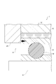
- the housing 12 has a first axial stop portion 20 and a second axial stop portion 22.
- the first axial stop portion 20 is provided adjacent to one end 23 on the first axial direction D1 side in the axial direction of the oil film damper 10 and regulates the movement of the outer ring 16 of the rolling bearing 8 in the first axial direction D1.
- the second axial stop portion 22 is provided adjacent to the other end 25 on the second axial direction D2 side in the axial direction of the oil film damper 10 and regulates the movement of the outer ring 16 of the rolling bearing 8 in the second axial direction D2. ..
- one end 23 of the oil film damper 10 is located closer to the compressor 2 than the other end 25.
- the housing 12 may be integrally configured as a whole including the first axial stop portion 20 and the second axial stop portion 22.
- each of the first axial stop portion 20 and the second axial stop portion 22 is made of a different material from the portion of the housing 12 excluding the first axial stop portion 20 and the second axial stop portion 22. You may.
- first axial stop portion 20 may be configured so as to be able to prevent the outer ring 16 from rotating in the circumferential direction.
- first axial stop portion 20 includes a pin member projecting toward the outer ring 16, and the outer ring 16 is formed with a fitting hole into which the pin member is fitted.
- the facing surface 26 of the first axial stop portion 20 faces the end surface 24 on one side in the axial direction of the outer ring 16.
- the facing surface 26 has a coefficient of static friction ⁇ smaller than that of the portion of the housing 12 excluding the first axial stop portion 20 and the second axial stop portion 22.
- the coefficient of static friction ⁇ of the facing surface 26 is, for example, a value measured by a test method according to JIS K7125.
- the first axial stop portion 20 has a coating film 28 forming the facing surface 26.
- the coating film 28 may contain amorphous carbon, molybdenum disulfide, carbon nitride, phosphate, nickel phosphorus, silver, gold, or fluororesin. Further, the coating film 28 (opposing surface 26 having a coefficient of static friction ⁇ ) may extend from the radial inner end 30 of the first axial stop portion 20 to the radial outer end 32 of the oil film damper 10 in the radial direction. good.
- the coefficient of static friction ⁇ of the facing surface 26 of the first axial stop portion 20 is set to the first. It can be made smaller than the portion of the housing 12 excluding the axial stop portion 20 and the second axial stop portion 22. Therefore, even when the thrust load S acting on the outer ring 16 is large, when the rotating shaft 4 vibrates, the frictional force acting between the outer ring 16 and the first axial stop portion 20 is suppressed, and the outer ring is suppressed. 16 can be moved outward in the radial direction. Therefore, the damping effect of the oil film damper 10 on the shaft vibration of the rotating shaft 4 can be sufficiently exerted. Further, during the operation of the turbocharger 1, vibration is transmitted from the rolling bearing 8 to the housing 12, and this vibration can be suppressed. According to the first embodiment, when the rotating shaft 4 vibrates, the outer ring 16 can be moved inward in the radial direction.
- the coating film 28 having a coefficient of static friction ⁇ extends from the radial inner end 30 of the first axial stop portion 20 to the radial outer end 32 of the oil film damper 10 in the radial direction. doing. Therefore, when the outer ring 16 moves in the radial direction relative to the housing 12 within the range allowed by the gap 21 of the oil film damper 10, the oil film is formed from the radial inner end 30 of the first axial stop portion 20. The effect of reducing the frictional force between the first axial stop portion 20 and the outer ring 16 can be enjoyed over the radial outer end 32 of the damper 10.
- the damping effect of the oil film damper 10 on the axial vibration of the rotating shaft 4 is improved. Can be easily realized.
- the coefficient of static friction ⁇ of the facing surface 26 of the first axial stop portion 20 is smaller than that of the housing 12 excluding the first axial stop portion 20 and the second axial stop portion 22.
- the present disclosure is not limited to this embodiment.
- the coefficient of static friction of the facing surface of the second axial stop 22 (the surface of the outer ring 16 facing the other end surface in the axial direction) is set to the first axial stop 20 and the second axial stop. It may be smaller than the portion of the housing 12 excluding 22.
- the turbocharger 1 according to the second embodiment of the present disclosure will be described.
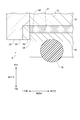
- the second embodiment is different from the first embodiment in that a coating film 31 is formed on the end surface 24 on one side in the axial direction of the outer ring 16 instead of the facing surface 26 of the first axial stop portion 20.
- the configuration other than that is the same as the configuration described in the first embodiment.
- the same components as those of the first embodiment are designated by the same reference numerals, and detailed description thereof will be omitted.
- the outer ring 16 has a coating film 31 that forms an end face 24 on one side in the axial direction.
- the coating film 31 is the same as the coating film 28 described in the first embodiment.
- the end face 24 on one side in the axial direction of the outer ring 16 is configured to have a coefficient of static friction ⁇ .
- the end face 24 on one side in the axial direction of the outer ring 16 may have a coefficient of static friction ⁇ in the entire region. That is, the coating film 31 may be formed over the entire region of the end face 24 on one side in the axial direction of the outer ring 16.
- the end face 24 on one side in the axial direction of the outer ring 16 is formed by the first axial stop portion 20 and the second. It is possible to have a coefficient of static friction ⁇ smaller than that of the portion of the housing 12 excluding the axial stop portion 22. Therefore, even when the thrust load S acting on the outer ring 16 is large, when the rotating shaft 4 vibrates, the frictional force acting between the outer ring 16 and the first axial stop portion 20 is suppressed, and the outer ring is suppressed. 16 can be moved outward in the radial direction. Therefore, the damping effect of the oil film damper 10 on the shaft vibration of the rotating shaft 4 can be sufficiently exerted.
- the coating film 31 having a coefficient of static friction ⁇ forms the entire region of the end face 24 on one side in the axial direction of the outer ring 16. Therefore, when the outer ring 16 moves in the radial direction relative to the housing 12 within the range allowed by the gap 21 of the oil film damper 10, the outer ring 16 covers the entire radial movement range of the outer ring 16. You can enjoy the effect of reducing the frictional force between the uniaxial direction stop portion 20 and the outer ring 16.
- the damping effect of the oil film damper 10 on the axial vibration of the rotating shaft 4 can be improved. It can be easily realized.
- the end face 24 on one side in the axial direction of the outer ring 16 has a coefficient of static friction ⁇ smaller than that of the housing 12 excluding the first axial stop portion 20 and the second axial stop portion 22.
- the present disclosure is not limited to this embodiment.
- the end face of the outer ring 16 on the other side in the axial direction may have a coefficient of static friction ⁇ smaller than that of the housing 12 except for the first axial stop 20 and the second axial stop 22. good.
- the turbocharger 1 according to the third embodiment of the present disclosure will be described.
- the third embodiment has a configuration different from that of the first embodiment, and the facing surface 26 of the first axial stop portion 20 has a coefficient of static friction ⁇ .
- the third embodiment is different from the first embodiment in that the material forming the first axial stop portion 20 is limited, but the other configurations are the same as the configurations described in the first embodiment.
- the same components as those of the first embodiment are designated by the same reference numerals, and detailed description thereof will be omitted.
- the first axial stop portion 20 may contain any one of copper, silver, gold, lead, sintered oil-impregnated metal, polyetheretherketone, polyimide, and polyphenylene sulfide. In this case, as shown in FIG. 5, the coating film 28 may not be formed on the first axial stop portion 20. In some embodiments, if the first axial stop 20 contains any of polyetheretherketone, polyimide, or polyphenylene sulfide, the first axial stop 20 may be impregnated with a solid lubricant. good.
- the solid lubricant is, for example, molybdenum disulfide, graphite, tungsten disulfide and the like.
- the first axial stop portion 20 contains any of the above-mentioned copper, silver, gold, lead, sintered oil-impregnated metal, polyetheretherketone, polyimide, and polyphenylene sulfide, the outer ring 16 It is possible to reduce the frictional force acting between the end surface 24 on one side in the axial direction and the facing surface 26 of the first axial stop portion 20. Further, according to the third embodiment, the step of forming the coating film 28 on the first axial stop portion 20 can be omitted.
- the first axial stop portion 20 contains any one of copper, silver, gold, lead, sintered oil-impregnated metal, polyetheretherketone, polyimide, and polyphenylene sulfide. Is not limited to this embodiment.
- the second axial stop 22 may include any of copper, silver, gold, lead, sintered oil-impregnated metal, polyetheretherketone, polyimide, polyphenylene sulfide.
- the second axial stop 22 comprises any of copper, silver, gold, lead, sintered oil-impregnated metal, polyetheretherketone, polyimide, polyphenylene sulfide, and the first shaft. It is configured to have heat resistance from the direction stopper 20. For example, the first axial stop 20 (located on the compressor 2 side) has heat resistance up to 200 degrees, while the second axial stop (located on the turbine 6 side) has heat resistance up to 300 degrees. Is configured to have.
- the first axial stop portion 20 may include a base portion 35 and an intermediate member 36.
- the base 35 is not particularly limited, but the intermediate member 36 includes any one of copper, silver, gold, lead, sintered oil-impregnated metal, polyetheretherketone, polyimide, and polyphenylene sulfide.
- the intermediate member 36 is arranged so as to have an opposing surface 26 facing the end surface 24 on one side in the axial direction of the outer ring 16.
- Such an intermediate member 36 may have a ring shape, for example, a resin ring.
- the intermediate member 36 since it is very easy to provide the intermediate member 36, it is possible to very easily improve the damping effect of the oil film damper 10 with respect to the shaft vibration of the rotating shaft 4.
- the intermediate member 36 may be arranged so that the radially outer end surface of the intermediate member 36 is located radially inside the radial outer end 32 of the oil film damper 10.
- the turbocharger 1 according to the fourth embodiment of the present disclosure will be described.
- the fourth embodiment is different from the first embodiment in that the coating film 28 is not formed and the facing surface 26 of the first axial stop portion 20 has a recess 40 (dimple 40A), but other configurations are different. It is the same as the configuration described in the first embodiment.
- the same components as those of the first embodiment are designated by the same reference numerals, and detailed description thereof will be omitted.
- the facing surface 26 of the first axial stop portion 20 has a recess 40 through which the oil of the oil film damper 10 can enter.
- the recess 40 includes dimples 40A (40) recessed from the facing surface 26 of the first axial stop portion 20.
- a plurality of dimples 40A are arranged so as to cover the entire circumferential direction of the facing surface 26 of the first axial stop portion 20. Further, a plurality of dimples 40A are arranged so as to cover the entire radial direction of the facing surface 26 of the first axial stop portion 20.
- the lubricating oil 11 supplied from the oil film damper 10 can be held in the dimples 40A included in the facing surface 26 of the first axial stop portion 20. Therefore, the coefficient of friction of the facing surface 26 of the first axial stop portion 20 can be reduced.
- the turbocharger 1 according to the fifth embodiment of the present disclosure will be described.
- the fifth embodiment is different from the fourth embodiment in that the recess 40 formed on the facing surface 26 of the first axial stop portion 20 includes the first groove 40B instead of the dimple 40A, but other than that.
- the configuration is the same as the configuration described in the fourth embodiment.
- the same components as those of the fourth embodiment are designated by the same reference numerals, and detailed description thereof will be omitted.
- the recess 40 has a plurality of first grooves extending in the radial direction from the radial outer end 32 of the oil film damper 10 to the radial inner end 30 of the first axial stop portion 20.
- a plurality of first grooves 40B are arranged along the circumferential direction of the facing surface 26 of the first axial stop portion 20.
- the lubricating oil 11 supplied from the oil film damper 10 is provided by including the plurality of first grooves 40B in the facing surface 26 of the first axial stop portion 20. It is allowed to flow through the first groove 40B, and the facing surface 26 of the first axial stop portion 20 can be more wetted with the lubricating oil 11. Therefore, the coefficient of friction of the facing surface 26 of the first axial stop portion 20 can be reduced.
- the turbocharger 1 according to the sixth embodiment of the present disclosure will be described.
- the sixth embodiment is different from the fourth embodiment in that the recess 40 formed on the facing surface 26 of the first axial stop portion 20 includes the second groove 40C instead of the dimple 40A, but other than that.
- the configuration is the same as the configuration described in the fourth embodiment.
- the same components as those of the fourth embodiment are designated by the same reference numerals, and detailed description thereof will be omitted.
- the recess 40 is located in the radial direction from the radial outer end 32 of the oil film damper 10 to the radial inner end 30 and the radial outer end 34 of the first axial stop portion 20.
- a plurality of second grooves 40C are arranged along the circumferential direction of the facing surface 26 of the first axial stop portion 20.
- the lubricating oil 11 supplied from the oil film damper 10 is seconded by including the second groove 40C in the facing surface 26 of the first axial stop portion 20.
- the lubricating oil 11 flows through the groove 40C and presses the end surface 24 on one side in the axial direction of the outer ring 16, so that the thrust load S acting on the outer ring 16 can be reduced.
- the lubricating oil 11 may leak.
- the second groove 40C extends to a position between the radial inner end 30 and the radial outer end 34 of the first axial stop portion 20, the lubricating oil 11 leaks. You don't have to.
- the facing surface 26 of the first axial stop portion 20 has recesses 40 (40A, 40B, 40C), but the present disclosure is not limited to this embodiment. .. In some embodiments, the facing surface of the second axial stop 22 may have a recess 40.
- the turbocharger (1) includes a rotating shaft (4), a rolling bearing (8) that rotatably supports the rotating shaft, and an outer ring (16) of the rolling bearing on the outer side in the radial direction.
- An oil film damper (10) provided and a first axial stop portion (20) and a second shaft provided adjacent to both ends of the oil film damper in the axial direction to regulate the axial movement of the outer ring.
- a housing (12) having a directional stop (22), and an axial end surface (24) of the outer ring, or the shaft of the outer ring of the first axial stop or the second axial stop.
- the facing surface (26) facing the directional end surface has a static friction coefficient smaller than that of the housing portion excluding the first axial stop portion and the second axial stop portion, or the oil of the oil film damper invades. Has a possible recess.
- the coefficient of static friction of the axial end surface of the outer ring or the facing surface of the first axial stop portion or the second axial stop portion is set to the first axial stop portion and the second axial stop portion. It can be made smaller than the housing part excluding the axial stop. Therefore, even when the axial load acting on the outer ring is large, the outer ring can be moved in the radial direction when the rotating shaft vibrates, and the effect of damping the oil film damper on the shaft vibration can be sufficiently exerted. can.
- the axial end face of the outer ring has the coefficient of static friction or the recess in the entire region of the axial end face.
- the facing surface having the coefficient of static friction or the recess is radially stopped in the first axial direction or in the second axial direction. It extends from the radial inner end of the stopper to the radial outer end of the oil film damper.
- the first axial stop portion or the second shaft From the radial inner end of the directional stop portion to the radial outer end of the oil film damper, the effect of reducing the frictional force between the first axial stop portion or the second axial stop portion and the outer ring can be enjoyed.
- the outer ring, the first axial stop portion, or the second axial stop portion is , Has a coating film (28, 31) forming the axial end face or the facing surface.
- the coating film is amorphous carbon, molybdenum disulfide, carbon nitride, phosphate, nickel phosphorus, silver, gold, or. Contains fluororesin.
- the shaft is formed by forming a coating film containing amorphous carbon, molybdenum disulfide, carbon nitride, phosphate, nickel phosphorus, silver, gold, or fluororesin.
- the coefficient of static friction of the directional end face or the facing surface can be effectively reduced.
- At least one of the outer ring, the first axial stop portion, and the second axial stop portion is made of copper. Contains any of silver, gold, lead, sintered oil-impregnated metal, polyetheretherketone, polyimide, and polyphenylene sulfide.
- At least one of the outer ring, the first axial stop portion, and the second axial stop portion is made of copper, silver, gold, lead, sintered oil-impregnated metal, and the like. Since it contains any of polyetheretherketone, polyimide, or polyphenylene sulfide, it is possible to reduce the frictional force acting between the outer ring and the first axial stop portion and between the outer ring and the second axial stop portion.
- the recess has a dimple (40A) recessed from the facing surface of the first axial stop portion or the second axial stop portion.
- the oil supplied from the oil film damper can be held in the dimples included in the facing surface of the first axial stop portion or the second axial stop portion. Therefore, the coefficient of friction of the facing surface of the first axial stop portion or the second axial stop portion can be reduced.
- the recess is provided in the radial direction from the radial outer end of the oil film damper to the first axial stop portion or the second axial direction. Includes a plurality of first grooves (40B) extending to the radial inner end of the stopper.
- the oil supplied from the oil film damper is made into the first groove by including the first groove on the facing surface of the first axial stop portion or the second axial stop portion.
- the sink and the facing surface of the first axial stop portion or the second axial stop portion can be further wetted with oil. Therefore, the coefficient of friction of the facing surface of the first axial stop portion or the second axial stop portion can be reduced.
- the recess in the configuration described in (1) above, in the radial direction, is formed from the radial outer end of the oil film damper to the first axial stop portion or the second shaft. It includes a plurality of second grooves (40C) extending to a position between the radial inner end of the directional stop and the radial outer end.
- the oil supplied from the oil film damper is made into the second groove by including the second groove on the facing surface of the first axial stop portion or the second axial stop portion. It is possible to reduce the axial load acting on the outer ring by flowing and pressing the axial end face of the outer ring.
Landscapes
- Engineering & Computer Science (AREA)
- Mechanical Engineering (AREA)
- General Engineering & Computer Science (AREA)
- Chemical & Material Sciences (AREA)
- Combustion & Propulsion (AREA)
- Chemical Kinetics & Catalysis (AREA)
- General Chemical & Material Sciences (AREA)
- Supercharger (AREA)
- Support Of The Bearing (AREA)
Priority Applications (5)
| Application Number | Priority Date | Filing Date | Title |
|---|---|---|---|
| US17/796,497 US11982199B2 (en) | 2020-02-20 | 2020-02-20 | Turbocharger |
| CN202080096743.7A CN115103954B (zh) | 2020-02-20 | 2020-02-20 | 涡轮增压器 |
| PCT/JP2020/006878 WO2021166180A1 (ja) | 2020-02-20 | 2020-02-20 | ターボチャージャ |
| DE112020005650.3T DE112020005650B4 (de) | 2020-02-20 | 2020-02-20 | Turbolader |
| JP2022501523A JP7373050B2 (ja) | 2020-02-20 | 2020-02-20 | ターボチャージャ |
Applications Claiming Priority (1)
| Application Number | Priority Date | Filing Date | Title |
|---|---|---|---|
| PCT/JP2020/006878 WO2021166180A1 (ja) | 2020-02-20 | 2020-02-20 | ターボチャージャ |
Publications (1)
| Publication Number | Publication Date |
|---|---|
| WO2021166180A1 true WO2021166180A1 (ja) | 2021-08-26 |
Family
ID=77390779
Family Applications (1)
| Application Number | Title | Priority Date | Filing Date |
|---|---|---|---|
| PCT/JP2020/006878 Ceased WO2021166180A1 (ja) | 2020-02-20 | 2020-02-20 | ターボチャージャ |
Country Status (5)
| Country | Link |
|---|---|
| US (1) | US11982199B2 (https=) |
| JP (1) | JP7373050B2 (https=) |
| CN (1) | CN115103954B (https=) |
| DE (1) | DE112020005650B4 (https=) |
| WO (1) | WO2021166180A1 (https=) |
Citations (5)
| Publication number | Priority date | Publication date | Assignee | Title |
|---|---|---|---|---|
| JPS6043137U (ja) * | 1983-09-01 | 1985-03-27 | 石川島播磨重工業株式会社 | 過給機軸受の給油装置 |
| JP2005172099A (ja) * | 2003-12-10 | 2005-06-30 | Koyo Seiko Co Ltd | ターボチャージャの軸受装置 |
| US20130224015A1 (en) * | 2011-08-30 | 2013-08-29 | Aktiebolaget Skf | Turbocharger, notably for a combustion engine |
| JP2014062557A (ja) * | 2012-09-20 | 2014-04-10 | Jtekt Corp | 軸受装置 |
| JP2019178756A (ja) * | 2018-03-30 | 2019-10-17 | 株式会社Ihi | 軸受構造および過給機 |
Family Cites Families (10)
| Publication number | Priority date | Publication date | Assignee | Title |
|---|---|---|---|---|
| JPH01127939U (https=) * | 1988-02-25 | 1989-08-31 | ||
| US4859090A (en) * | 1988-08-25 | 1989-08-22 | Honeywell Inc. | Rotating conductive heat transfer device |
| JP2009270612A (ja) | 2008-05-07 | 2009-11-19 | Toyota Motor Corp | ターボチャージャーの軸受構造 |
| US8961128B2 (en) | 2009-08-26 | 2015-02-24 | Honeywell International Inc. | Bearing spacer and housing |
| EP2787181B1 (en) | 2011-11-30 | 2019-01-09 | Mitsubishi Heavy Industries, Ltd. | Radial turbine |
| JP6678086B2 (ja) * | 2016-08-12 | 2020-04-08 | ミネベアミツミ株式会社 | ターボチャージャー用転がり軸受および回り止め機構 |
| JP2018063018A (ja) * | 2016-10-14 | 2018-04-19 | Ntn株式会社 | 過給機の軸受装置 |
| JP6856404B2 (ja) * | 2017-02-24 | 2021-04-07 | 本田技研工業株式会社 | スクイズフィルムダンパベアリング装置 |
| DE102017222919A1 (de) * | 2017-12-15 | 2019-06-19 | Aktiebolaget Skf | Wälzlager |
| JP7107371B2 (ja) | 2018-07-27 | 2022-07-27 | 株式会社Ihi | 軸受構造および過給機 |
-
2020
- 2020-02-20 WO PCT/JP2020/006878 patent/WO2021166180A1/ja not_active Ceased
- 2020-02-20 CN CN202080096743.7A patent/CN115103954B/zh active Active
- 2020-02-20 JP JP2022501523A patent/JP7373050B2/ja active Active
- 2020-02-20 US US17/796,497 patent/US11982199B2/en active Active
- 2020-02-20 DE DE112020005650.3T patent/DE112020005650B4/de active Active
Patent Citations (5)
| Publication number | Priority date | Publication date | Assignee | Title |
|---|---|---|---|---|
| JPS6043137U (ja) * | 1983-09-01 | 1985-03-27 | 石川島播磨重工業株式会社 | 過給機軸受の給油装置 |
| JP2005172099A (ja) * | 2003-12-10 | 2005-06-30 | Koyo Seiko Co Ltd | ターボチャージャの軸受装置 |
| US20130224015A1 (en) * | 2011-08-30 | 2013-08-29 | Aktiebolaget Skf | Turbocharger, notably for a combustion engine |
| JP2014062557A (ja) * | 2012-09-20 | 2014-04-10 | Jtekt Corp | 軸受装置 |
| JP2019178756A (ja) * | 2018-03-30 | 2019-10-17 | 株式会社Ihi | 軸受構造および過給機 |
Also Published As
| Publication number | Publication date |
|---|---|
| CN115103954A (zh) | 2022-09-23 |
| CN115103954B (zh) | 2024-02-09 |
| DE112020005650T5 (de) | 2022-09-01 |
| JP7373050B2 (ja) | 2023-11-01 |
| US20230053136A1 (en) | 2023-02-16 |
| DE112020005650B4 (de) | 2025-11-13 |
| US11982199B2 (en) | 2024-05-14 |
| JPWO2021166180A1 (https=) | 2021-08-26 |
Similar Documents
| Publication | Publication Date | Title |
|---|---|---|
| US5522667A (en) | Ball bearing for turbocharger | |
| EP1769167B1 (en) | Multi-thickness squeeze film damper layer between bearing cartridge and housing | |
| JP5071150B2 (ja) | ターボチャージャ用軸受装置 | |
| EP2078825A2 (en) | Turbocharger | |
| JP2010138757A (ja) | ターボチャージャ | |
| US9989086B2 (en) | Sliding bearing | |
| WO2018173502A1 (ja) | ティルティングパッド軸受用の軸受パッド、ティルティングパッド軸受及び回転機械 | |
| JP2008185107A (ja) | 玉軸受 | |
| JPH0617825A (ja) | 転動子を有するラジアル・スラスト複合軸受 | |
| WO2006095777A1 (ja) | 転がり軸受、カムシャフト装置、及び、カムシャフト支持装置 | |
| WO2018016268A1 (ja) | フォイル軸受 | |
| KR20020015303A (ko) | 일체형 볼베어링 터보 과급기용 로터 조립체 | |
| KR100649976B1 (ko) | 저비용 볼 베어링을 갖춘 터보 과급기 로터 | |
| JP2009203846A (ja) | ターボチャージャ用軸受装置 | |
| JP2003247540A (ja) | 転がり軸受及びロッドエンド軸受 | |
| WO2021166180A1 (ja) | ターボチャージャ | |
| JPH074439A (ja) | 高速アンギュラ玉軸受 | |
| WO2007116753A1 (ja) | 転がり軸受、及び、これを用いた過給機 | |
| JP5829397B2 (ja) | ターボチャージャの回転軸の軸受方法及び装置 | |
| JP2008002522A (ja) | フォロア軸受 | |
| JP4259208B2 (ja) | 転がり軸受装置 | |
| JP2009203845A (ja) | ターボチャージャ用軸受装置 | |
| JPH06307450A (ja) | 静圧気体軸受 | |
| KR100867972B1 (ko) | 고속 회전축 시스템에서의 가스 포일베어링 마모방지시스템 | |
| JP2023149811A (ja) | 玉軸受 |
Legal Events
| Date | Code | Title | Description |
|---|---|---|---|
| 121 | Ep: the epo has been informed by wipo that ep was designated in this application |
Ref document number: 20920457 Country of ref document: EP Kind code of ref document: A1 |
|
| WWE | Wipo information: entry into national phase |
Ref document number: 112020005650 Country of ref document: DE |
|
| ENP | Entry into the national phase |
Ref document number: 2022501523 Country of ref document: JP Kind code of ref document: A |
|
| 122 | Ep: pct application non-entry in european phase |
Ref document number: 20920457 Country of ref document: EP Kind code of ref document: A1 |
|
| WWG | Wipo information: grant in national office |
Ref document number: 112020005650 Country of ref document: DE |