WO2021161439A1 - 空気調和装置 - Google Patents
空気調和装置 Download PDFInfo
- Publication number
- WO2021161439A1 WO2021161439A1 PCT/JP2020/005487 JP2020005487W WO2021161439A1 WO 2021161439 A1 WO2021161439 A1 WO 2021161439A1 JP 2020005487 W JP2020005487 W JP 2020005487W WO 2021161439 A1 WO2021161439 A1 WO 2021161439A1
- Authority
- WO
- WIPO (PCT)
- Prior art keywords
- heat exchanger
- unit
- refrigerant
- outdoor
- air conditioner
- Prior art date
- Legal status (The legal status is an assumption and is not a legal conclusion. Google has not performed a legal analysis and makes no representation as to the accuracy of the status listed.)
- Ceased
Links
Images












Classifications
-
- F—MECHANICAL ENGINEERING; LIGHTING; HEATING; WEAPONS; BLASTING
- F24—HEATING; RANGES; VENTILATING
- F24F—AIR-CONDITIONING; AIR-HUMIDIFICATION; VENTILATION; USE OF AIR CURRENTS FOR SCREENING
- F24F1/00—Room units for air-conditioning, e.g. separate or self-contained units or units receiving primary air from a central station
- F24F1/06—Separate outdoor units, e.g. outdoor unit to be linked to a separate room comprising a compressor and a heat exchanger
- F24F1/14—Heat exchangers specially adapted for separate outdoor units
- F24F1/16—Arrangement or mounting thereof
-
- F—MECHANICAL ENGINEERING; LIGHTING; HEATING; WEAPONS; BLASTING
- F24—HEATING; RANGES; VENTILATING
- F24F—AIR-CONDITIONING; AIR-HUMIDIFICATION; VENTILATION; USE OF AIR CURRENTS FOR SCREENING
- F24F1/00—Room units for air-conditioning, e.g. separate or self-contained units or units receiving primary air from a central station
- F24F1/06—Separate outdoor units, e.g. outdoor unit to be linked to a separate room comprising a compressor and a heat exchanger
- F24F1/14—Heat exchangers specially adapted for separate outdoor units
- F24F1/18—Heat exchangers specially adapted for separate outdoor units characterised by their shape
-
- F—MECHANICAL ENGINEERING; LIGHTING; HEATING; WEAPONS; BLASTING
- F24—HEATING; RANGES; VENTILATING
- F24F—AIR-CONDITIONING; AIR-HUMIDIFICATION; VENTILATION; USE OF AIR CURRENTS FOR SCREENING
- F24F1/00—Room units for air-conditioning, e.g. separate or self-contained units or units receiving primary air from a central station
- F24F1/06—Separate outdoor units, e.g. outdoor unit to be linked to a separate room comprising a compressor and a heat exchanger
- F24F1/46—Component arrangements in separate outdoor units
-
- F—MECHANICAL ENGINEERING; LIGHTING; HEATING; WEAPONS; BLASTING
- F24—HEATING; RANGES; VENTILATING
- F24F—AIR-CONDITIONING; AIR-HUMIDIFICATION; VENTILATION; USE OF AIR CURRENTS FOR SCREENING
- F24F1/00—Room units for air-conditioning, e.g. separate or self-contained units or units receiving primary air from a central station
- F24F1/06—Separate outdoor units, e.g. outdoor unit to be linked to a separate room comprising a compressor and a heat exchanger
- F24F1/46—Component arrangements in separate outdoor units
- F24F1/48—Component arrangements in separate outdoor units characterised by air airflow, e.g. inlet or outlet airflow
- F24F1/50—Component arrangements in separate outdoor units characterised by air airflow, e.g. inlet or outlet airflow with outlet air in upward direction
Definitions
- the present invention relates to an air conditioner, and particularly to an air conditioner in which a plurality of indoor units are assigned to one outdoor unit.
- the heat exchanger of the outdoor unit absorbs the heat of the outside air in the case of heating operation that heats the room, and the heat exchange of the outdoor unit in the case of cooling operation that cools the room. It has a function to release heat to the outside air by a vessel.
- the air conditioner is composed of an outdoor unit installed outdoors and an indoor unit installed indoors.
- the indoor unit and the outdoor unit are a heat exchanger that exchanges heat between air and a refrigerant, and a heat exchanger. It is equipped with a blower fan that allows air to flow and a refrigerant pipe that connects the outdoor unit and the indoor unit.
- VRF Very refrigerant flow
- indoor units connected to the outdoor unit by a refrigerant pipe
- An air conditioner is used.
- Such an air conditioner is a so-called "multi air conditioner system”.
- the outdoor unit that distributes the refrigerant to the plurality of indoor units is configured as described in, for example, Japanese Patent Application Laid-Open No. 2011-102662 (Patent Document 1).
- the outdoor unit in Patent Document 1 is an outdoor unit called a top-flow type having an air exhaust fan (hereinafter referred to as an outdoor fan) at the upper part of the outdoor unit. Therefore, the heat exchanger is arranged so as to extend vertically from the bottom installation plate toward the outdoor fan from the bottom installation plate (drain pan) of the housing for accommodating the functional parts of the outdoor unit. That is, the heat exchangers are arranged along the direction of gravity, and the heat exchangers have a flat plate-shaped heat exchanger bent along the side surface of the housing.
- Increasing the air suction area of the heat exchanger not only has the effect of expanding the heat transfer area, but also can reduce the wind speed flowing into the heat exchanger if the air volume of the outdoor unit is the same. Therefore, the ventilation resistance of the air when passing through the heat exchanger is reduced, and the input of the outdoor fan can be reduced if the air volume is the same. On the contrary, if the input of the outdoor fan is the same, the larger the air suction area, the more the air volume can be increased. This increase in air volume is effective in improving the heat exchange capacity and energy saving.
- the number of refrigerant paths is the number of paths (flow paths) through which the refrigerant branches and flows inside the heat exchanger.
- the wind speed of the air flowing into the heat exchanger tends to be faster at the upper part near the outdoor fan and slower at the lower part far from the outdoor fan. be. Therefore, during the heating operation, it is conceivable that the refrigerant first passes through the lower region of the heat exchanger having a low wind speed, and then passes through the upper region of the heat exchanger having a high wind speed. As a result, the influence of the wind speed distribution can be reduced by allowing the refrigerant to flow in both the slow wind speed region and the high wind speed region in the refrigerant path.
- the refrigerant flows through the lower region of the heat exchanger and then further to the upper region of the heat exchanger, so that the length of the refrigerant path is long and the refrigerant pressure loss tends to be too large.
- An object of the present invention is to provide an air conditioner capable of solving at least one of the above-mentioned problems.
- the first feature of the present invention is that the heat exchangers constituting the top-flow type outdoor unit are divided into a plurality of unit heat exchangers and arranged side by side, and the unit heat exchangers are arranged at the bottom of the housing of the outdoor unit.
- the unit heat exchanger is arranged so as to extend vertically from the bottom installation plate toward the outdoor fan from the installation plate, and the cross section of the unit heat exchanger perpendicular to the bottom installation plate is a linear first. Between a side and a pair of linear second sides that are bent and connected to both sides of this first side and longer than the length of the first side, and between adjacent second sides of adjacent unit heat exchangers. A gap is formed in the space, and the first side is aligned along the long side of the bottom installation plate.
- the second feature of the present invention is that the heat exchangers constituting the top-flow type outdoor unit are divided into four or more unit heat exchangers and arranged side by side, and the unit heat exchanger is the bottom installation plate of the outdoor unit. It is arranged so as to extend vertically from the bottom installation plate from the side toward the outdoor fan, and the refrigerant path of the unit heat exchanger covers at least both the lower region and the upper region of the unit heat exchanger once. Is being passed, where it is.
- the total air suction area of the heat exchanger can be expanded as compared with the air suction area of the heat exchanger arranged along the periphery of the housing of the outdoor unit.
- the flow rate of the refrigerant flowing through one unit heat exchanger can be reduced, and the refrigerant pressure loss can be reduced.
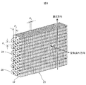
- FIG. 1 It is a block diagram explaining the outline of the air conditioner. It is external perspective view of the outdoor unit of the air conditioner which becomes embodiment of this invention. It is an external perspective view explaining the structure of the heat exchanger used for the outdoor unit. It is external perspective view of the heat exchanger used for the outdoor unit of the air conditioner which becomes the embodiment of this invention. It is a top view which shows the upper surface of the heat exchanger shown in FIG. It is a top view which shows the upper surface of the unit heat exchanger shown in FIG. It is external perspective view of the outdoor unit in the state which the housing part was removed from the outdoor unit shown in FIG. It is a front view which looked at the outdoor unit shown in FIG. 1 from the front panel side. Internal devices are shown by broken lines. FIG.
- FIG. 5 is an external perspective view of the outdoor unit in a state where the upper housing is removed from the outdoor unit shown in FIG. It is a block diagram explaining the 1st modification of the Embodiment of this invention. It is a block diagram explaining the 2nd modification of the Embodiment of this invention. It is a block diagram explaining the 3rd modification of embodiment of this invention. It is a characteristic diagram which shows the wind speed of the heat exchanged air of the heat exchanger extending in the vertical direction from the bottom part of an installation. It is explanatory drawing explaining the relationship between the piping structure of the heat exchanger which becomes the embodiment of this invention, and a refrigerant path.
- FIG. 1 shows an outline of a refrigerating cycle in a VRF type air conditioner, and particularly describes a refrigerating cycle during a heating operation.
- the high-temperature and high-pressure gas refrigerant discharged from the compressor 10 passes through the refrigerant pipe 11 and the four-way valve 12 and flows to the gas side blocking valve 13. From here, the indoor unit 15 and the gas side blocking valve 13 are connected by the gas refrigerant pipe 14. The gas refrigerant flowing out from the gas side blocking valve 13 flows to the indoor heat exchanger 16 in the indoor unit 15.
- the indoor unit 15 is provided in two living rooms A and B. Of course, it can be installed in more rooms.
- Air is flowing through the indoor heat exchanger 16 by the indoor fan 17, and the air takes away the heat of the refrigerant and is supplied to the room. Inside the indoor heat exchanger 16, the refrigerant is cooled and liquefied. The liquefied liquid refrigerant flows through the liquid refrigerant pipe 18 to the liquid side blocking valve 19.
- the refrigerant flowing into the outdoor unit 20 from the liquid side blocking valve 19 is decompressed by the outdoor expansion valve 21 housed in the outdoor unit 20, becomes a low-temperature low-pressure gas-liquid two-phase state, and goes outdoors via the refrigerant tank 22. It flows to the heat exchanger 23. Outdoor air is flowing through the outdoor heat exchanger 23 by the outdoor fan 24, and the refrigerant is depressurized so as to be lower than the outdoor air temperature flowing through the heat exchanger 23. Therefore, the heat exchanger 23. At 23, the heat of the outdoor air is absorbed and evaporated.
- the gas refrigerant evaporated and gasified by the outdoor heat exchanger 23 passes through the four-way valve 12, passes through the accumulator 25, returns to the compressor 10, and is again compressed into a high-temperature and high-pressure gas by the compressive action of the compressor 10. ..
- the heating operation can be continued by repeating these steps.
- the four-way valve 12 connects the discharge pipe of the compressor 10 and the outdoor heat exchanger 23, and the connection is switched so that the gas side blocking valve 19 and the accumulator 25 are connected.
- the flow directions of the refrigerant flowing through the outdoor heat exchanger 23 and the indoor heat exchanger 16 are reversed.
- the gas refrigerant condenses and liquefies, and in the indoor heat exchanger 16, the liquid refrigerant evaporates and gasifies. By repeating these steps, the cooling operation can be continued.
- FIG. 2 shows the appearance of the top-flow type outdoor unit 20 in the VRF type air conditioner.
- the outdoor unit 20 is composed of a lower housing 20BM and an upper housing 20UP attached above the lower housing 20BM.
- a front panel 26 is attached to the front side of the lower housing 20BM so that the front panel 26 can be opened with one side as the center of rotation for repair and maintenance while improving the appearance.
- the lower housing 20BM is mounted on the bottom installation plate 31.
- Various components constituting the outdoor unit 20 are housed in the lower housing 20BM.
- a heat exchanger, a compressor, an accumulator, a refrigerant tank, a control box, etc. are housed, and since the lower housing 20BM is mounted on the bottom installation plate 31, these components are also mounted on the bottom installation plate 31. It will be placed.
- two bellmouth-shaped air outlets 27 are formed in the upper housing 20UP, and an outdoor fan 24 is arranged in these two air outlets 27. Therefore, when the outdoor fan 24 is rotated, the air to be heat-exchanged is sucked from the back surface 20B side of the lower housing 20BM and the side surface 20S side of the lower housing 20BM as shown by the arrows, and the sucked air. Is heat-exchanged by an internal heat exchanger and discharged from the air discharge port 27 as shown by an arrow.
- FIG. 3 shows the appearance of a general heat exchanger 23, and shows the configuration of the fin tube type heat exchanger 23 used in the outdoor unit 20.
- the heat exchanger 23 is composed of at least a heat transfer tube 28 through which a refrigerant flows and a plate-shaped heat transfer fin 29.
- the heat transfer fin 29 is made of a material having good heat transfer property such as an aluminum alloy, and its plate thickness is about 0.1 mm.
- the heat transfer tube 28 is also made of a material having good heat transfer property such as copper or an aluminum alloy.
- the heat transfer fins 29 are defined at a predetermined interval (Pf), and air flows through the interval Pf.
- the heat transfer tube 28 is used in a state where one end face is bent into a "U" shape in order to reduce the number of brazing points.
- a plate-shaped heat transfer fin 29 is inserted in a place where a plurality of heat transfer tubes 28 whose one end surface is bent in a "U" shape are arranged side by side. Then, by expanding the heat transfer tube 28 after that, the heat transfer tube 28 and the heat transfer fin 29 come into close contact with each other.
- the heat transfer tube 28 penetrates a plurality of heat transfer fins 29 in a form orthogonal to the plane portion of the heat transfer fins 29.
- the distance between the adjacent heat transfer tubes in the longitudinal direction of the heat transfer fins 29 is determined to be a predetermined interval (Pt), and the distance between the adjacent heat transfer tubes 28 in the lateral direction is determined to be a predetermined interval (Pc).
- Pt predetermined interval
- Pc predetermined interval
- the number of heat transfer tubes 28 in the height direction (gravity direction) of the heat exchanger 23 is referred to as the number of stages, and the number in the direction in which air flows is referred to as the number of rows.
- the heat exchanger 23 has “4 rows and 12 stages”.
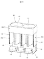
- 4 and 5 show typical embodiments of the present invention.
- 4 and 5 show the outdoor heat exchanger (hereinafter, simply referred to as a heat exchanger) 30 and the bottom installation plate 31 according to the present embodiment extracted from the outdoor unit 20.
- the heat exchanger 30 is housed within the range of the bottom installation plate 31.
- the component parts of the outdoor unit 20 are placed on the bottom installation plate 31, and also function as a so-called drain pan.
- the bottom installation plate 31 is formed in a rectangular shape including a long side and a short side, and unit heat exchangers described later are linearly arranged and installed along the long side.
- the bottom installation plate 31 of the outdoor unit 20 is installed at an installation location such as the roof of a building, and the heat exchanger 30 is mounted on the bottom installation plate 31. It is placed.
- the heat exchanger 30 is divided into a plurality of (here, four) unit heat exchangers 30U.
- each unit heat exchanger 30U is configured such that the longitudinal direction of the heat transfer fins 29 extends along the vertical direction (gravitational direction) from the bottom installation plate 31 toward the outdoor fan 24. There is.
- Each unit heat exchanger 30U has the same shape and the same dimensions, thereby improving productivity.
- the unit heat exchanger 30U is determined to have a special shape in order to expand the air suction area. That is, a shape crossed by a plane orthogonal to the longitudinal direction of the heat transfer fin 29 is formed in an "isosceles trapezoid", and among the sides forming this "isosceles trapezoid", the opposite sides are long sides parallel to each other. The shape is such that the side (lower bottom) is removed. In other words, this "isosceles trapezoid" can be said to be a modified "V" shape.
- the heat exchangers 30 constituting the top-flow type outdoor unit 20 are divided into a plurality of unit heat exchangers 30U and arranged side by side so as to be aligned linearly.
- the unit heat exchanger 30U is arranged so as to extend vertically from the bottom installation plate 31 toward the air fan 24 from the bottom installation plate 31 of the outdoor unit 20.
- the cross-sectional shape of the unit heat exchanger 30U crossed in a plane extending in the vertical direction extending from the bottom installation plate 31 is connected to the linear first side 32 so as to be bent on both sides of the first side 32.
- the shape is an "isosceles trapezoid" formed from a pair of linear second sides 33 longer than the length of the first side 32.
- the first side 32 of the plurality of unit heat exchangers 30U are arranged side by side along the long side of the bottom installation plate 31.
- the connecting portion between the first side 32 which is the "upper bottom” and the second side 33 which is the "leg” is formed in an arc shape having a predetermined curvature. This ensures a smooth flow of refrigerant.
- the space connecting the second side 33 on the side facing the first side 32 is the open side, and the compressor 10, the refrigerant tank 22, and the accumulator 25 are arranged on this open side as described later. .. Then, as shown in FIG. 5, the heat-exchanged air flows through the first side 32 and the second side 33 into the space on the open side as shown by the arrows. The heat-exchanged air that has flowed into the open side is exhausted from the air discharge port 27 by the outdoor fan 24.
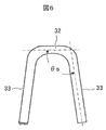
- the angle between the first side 32 and the second side 33 of the unit heat exchanger 30U is the first side 32 and the second side when viewed on the open side where the heat exchanged air flows out.
- the angle formed by the two sides 33 is set to a inferior angle ( ⁇ s) of 90 ° or more and less than 180 °. In this embodiment, it is set to about 100 °.
- the length of the second side (leg) 33 is formed longer than the length of the first side (upper base) 32.
- the cross-sectional shape of the unit heat exchanger 30U cross-sectionald in a plane extending in the vertical direction extending from the bottom installation plate 31 is such that the second sides 33 on both sides of the first side 32 face each other outward. In other words, it is tilted away.
- the second sides 33 of the adjacent unit heat exchangers 30U facing each other have a spread angle ( ⁇ ) of about 20 °. Therefore, even if the unit heat exchangers 30U are arranged side by side so as to be adjacent to each other, a space through which air passes is formed between the second sides 33, and the heat exchange capacity can be improved. Further, since it has a spreading angle ( ⁇ ), a sufficient amount of air can be sent to the second side 33.
- the vertical length (Lh) of the unit heat exchanger 30U is determined to be longer than the projected length (Ldh1) of the second side 33 of the unit heat exchanger 30U, and has an elongated shape as a whole. It is said that.
- the projected length (Ldh1) corresponds to the height of the "isosceles trapezoid".
- the first side 32 of the plurality of unit heat exchangers 30U is arranged in a straight line along the long side of the bottom installation plate 31. Since the unit heat exchanger 30U has the second side 33, it is practically difficult to arrange it on the short side of the bottom installation plate 31, and it is not arranged on the short side in the present embodiment. ..
- the bottom installation plate 31 has a long side determined to be the length (Lw) and a short side determined to be the length (Ld). Then, four unit heat exchangers 30U are arranged in a straight line along the long side of the bottom installation plate 31. Therefore, four times the length (Lwh1) on the open side of the unit heat exchanger 30U is substantially equal to the length (Lw) of the long side of the bottom installation plate 31.
- the length (Lwh1) on the open side of the unit heat exchanger 30U is formed to be longer than the length (Lwh2) of the first side 32.
- the length (Lwh1) on the open side of the unit heat exchanger 30U is determined to be about twice the length (Lwh2) of the first side 32. ..
- the short side of the bottom installation plate 31 is divided into two regions, a heat exchanger arranging region and a mechanical component arranging region, and the short side length (Ldh1) region is defined as a heat exchanger arranging region.
- the region of the length of the short side (Ldh2) is defined as the mechanical component placement region.
- Ldh1 / LLd ⁇ 0.7, and the length of the short side (Ldh2) of the mechanical component arrangement region is determined to be 200 mm or more. The reason for setting such a length is to arrange the compressor 10, the refrigerant tank 22, and the accumulator 25.
- the air suction area of the heat exchanger is formed in a flat shape when the length in the height direction (gravity direction) is the same, for example, in the heat exchanger as in Patent Document 1.
- the air suction area of the heat exchanger is determined by the length in the height direction and the length in the width direction.
- a plurality of unit heat exchangers 30U formed in an isosceles trapezoidal shape are connected to form a "bellows" shape. Since the length of the second side 33, which is an isosceles trapezoidal "leg", is added, the air suction area of the heat exchanger can be increased.
- FIGS. 7 and 8 as described above, in this embodiment, four unit heat exchangers 30U are provided. Then, one outdoor fan 24 is assigned to the two unit heat exchangers 30U, and each outdoor fan 24 is built in the upper housing 10UP.
- the heat exchangers 30U are arranged in the heat exchanger arrangement area (area indicated by the short side Ldh1) of the bottom installation plate 31, and the mechanical component arrangement area (indicated by the short side Ldh2) of the bottom installation plate 31.
- a compressor 10, a refrigerant tank 22, and an accumulator 25 are arranged in the region).
- the mechanical component placement area is arranged closer to the front panel 26 (see FIG. 2).
- the compressor 10, the refrigerant tank 22, and the accumulator 25 are installed so as to have an axis perpendicular to the bottom installation plate 31.
- the compressor 10 is provided corresponding to the two unit heat exchangers 30U, and the refrigerant tank 22 and the accumulator 25 are shared by one each. It is advantageous that the accumulator 25 is close to the compressor 10 in terms of layout, and the accumulator 25 is arranged between the compressors 10.
- the control box 34 in which the inverter for controlling the compressor 10 and the outdoor fan 24, the control circuit for controlling the four-way valve 12 and the outdoor expansion valve 21, the temperature sensor input, and the like are housed is also a mechanical component arrangement area. It can be installed in the space above the space, and the space utilization rate can be improved.
- control box 34 is arranged above the refrigerant tank 22 and the compressor 10 adjacent thereto, but as shown in FIG. 8, above the accumulator 25 and the compressor 10 adjacent thereto.
- the control box 34 can also be arranged.
- the compressor 10 and the control box 34 often require parts replacement during maintenance and repair.
- a compressor, a control box, and the like are installed inside covered with a heat exchanger. For this reason, when parts are replaced during maintenance or repair, it is necessary to reach inside the heat exchanger, which causes a problem that maintenance and repair are complicated and take a lot of time.
- the mechanical component arrangement area (the area indicated by the short side Ldh2) is arranged adjacent to the front panel 26. Therefore, if the front panel 26 is opened, the mechanical component can be immediately touched. By receiving the message, it is possible to achieve the effect and effect of easy maintenance and repair.
- the outdoor fan 24 is arranged above the partition plate 35, and the bellmouth-shaped air outlet 27 is arranged above the outdoor fan 24.
- the bell mouth-shaped air discharge port 27 has an effect of reducing the resistance due to the blowing of air and improving the fan air volume by gently expanding the air flow from the outdoor fan 24.
- one outdoor fan 24 corresponds to two unit heat exchangers 30U.
- the unit heat exchanger 30U is configured to flow air for heat exchange from the outside to the inside open side of the first side 32 and the second side 33. Therefore, when the outer portion and the outdoor fan 24 communicate with each other, air flows into the outdoor fan 24 without passing through the unit heat exchanger 30U.
- the partition plate 35 is arranged above the unit heat exchanger 30U so as to close the space formed between the adjacent unit heat exchangers 30U and the outdoor fan 24.
- the partition plate 35 is formed in a shape that follows the shape of the upper surface of the unit heat exchanger 30U, and the air to be heat exchanged is below the partition plate 35 when viewed in the height direction. It flows to the outdoor fan 24 side through the heat transfer fin 29 in the region. It is also possible to provide an outdoor fan 24 for each unit heat exchanger 30U. In this case, each unit heat exchanger 30U may be made independent and one outdoor fan 24 may be installed.
- the heat exchanger is arranged along the side surface of the housing of the outdoor unit. For this reason, mechanical parts such as a compressor are arranged inside the heat exchanger. Then, for example, when taking out the compressor placed inside the housing for repair, it is necessary to take care not to damage the heat exchanger, which causes a problem that maintenance is complicated and it takes a long time to do so. rice field.
- the unit heat exchangers 30U are arranged in a straight line along the long side of the bottom installation plate 31.
- an area for arranging the mechanical parts can be secured adjacent to the front panel 26. That is, the bottom installation plate 31 is divided into two regions along the short side, one region is used as a heat exchanger arrangement region, and the other region is used as a mechanism component arrangement region.
- the heat exchanger is divided with the shape in which the heat exchanger is arranged around the housing of the outdoor unit as in Patent Document 1, the bent portions of the heat transfer tubes are always formed at both ends of each of the divided heat exchangers. And the pop-out of piping groups such as distributors and capillary tubes connected to control the flow of refrigerant requires extra space, which leads to a reduction in the heat transfer area of the heat exchanger. Become.
- the ends of adjacent unit heat exchangers 30U are unlikely to interfere with each other, so that the heat transfer area can be increased while increasing the number of divisions of the heat exchanger. It is possible to increase.
- the number of outdoor units described above is one, but two outdoor units may be used.
- the arrangement configuration of the heat exchanger in this case will be briefly described.
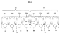
- FIG. 10 shows a configuration in which the unit heat exchangers 30U of the two outdoor units 20 are arranged close to the long side of the bottom installation plate 31.
- a spread angle ( ⁇ ) is formed between the second sides 33 adjacent to each other. Even if the housings of the outdoor units 20 are installed side by side in close contact with each other, a sufficient amount of air can flow from the formed portion of the spreading angle ( ⁇ ) to the unit heat exchanger due to the presence of the spreading angle ( ⁇ ). ..
- FIG. 11 shows a configuration in which the two outdoor units 20 are arranged in close contact with each other so as to be staggered.
- the outdoor unit 20 on the left side sucks air only from the upper side in the figure
- the outdoor unit 20 on the right side sucks air only from the lower side in the figure. This makes it easier for each outdoor unit 20 to suck in a sufficient amount of air.
- the outdoor units 20 can be arranged close to each other, so that two outdoor units can be arranged in a limited installation place, and the installation density of the outdoor units 20 can be improved. can.
- the actions and effects of the embodiment shown in FIG. 5 described above are exhibited.
- FIG. 12 shows a modified example of the unit heat exchanger 30U.
- the shape of the unit heat exchanger 30U shown in FIG. 5 described above is an “isosceles trapezoid” or a modified “V” shape, but the shape of the unit heat exchanger 30U shown in FIG. 12 is a “U” shape.
- Each unit heat exchanger 30U has the same shape and the same dimensions.
- the cross-sectional shape of the unit heat exchanger 30U cross-sectionald in a plane extending in the vertical direction extending from the bottom installation plate 31 is a linear first side 32-1 and the first side 32-1. It is connected so as to be bent on both sides of the above, and has a "U" shape formed from a pair of linear second sides 33-1 longer than the length of the first side 32-1.
- the first side 32-1 of the plurality of unit heat exchangers 30U are arranged side by side along the long side of the bottom installation plate 31.
- the connecting portion between the first side 32-1 and the second side 33-1 is formed in an arc shape having a predetermined curvature. This ensures a smooth flow of refrigerant.
- the space connecting the second side 33-1 on the side facing the first side 32-1 is the open side, and the compressor 10, the refrigerant tank 22, and the accumulator 25 are arranged on this open side as described later. Will be. Then, the heat-exchanged air flows into the space on the open side through the first side 32-1 and the second side 33-1. The heat-exchanged air that has flowed into the open side is exhausted from the air discharge port 27 by the outdoor fan 24.
- the angle between the first side 32-1 and the second side 33-1 of the unit heat exchanger 30U is the first when viewed on the open side where the heat-exchanged air flows out.
- the angle formed by the side 32-1 and the second side 33-1 is set to an inferior angle of 90 °.
- the space forming member 36 is arranged between the adjacent second sides 33-1 of the adjacent unit heat exchangers 30U.
- the space forming member 36 prevents the adjacent second sides 33-1 of the adjacent unit heat exchangers 30U from coming into close contact with each other.
- the space forming member 36 may be configured to prevent air from passing through, or may be a part of the unit heat exchanger 30U.
- a plurality of unit heat exchangers 30U formed in a "U" shape are connected to form a "bellows" shape, so that the second side 33- Since the length of 1 is added, the air suction area of the exchanger can be increased.
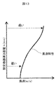
- FIG. 13 shows the wind speed distribution in the height direction of the heat exchanger of the outdoor unit called the top flow type shown in FIG.
- the wind speed in the upper region of the heat exchanger near the outdoor fan 24 is high, and the wind speed in the lower region of the heat exchanger far from the outdoor fan 24 is slow. This is caused by the ventilation resistance of the air flowing from the lower region to the upper region of the heat exchanger inside the heat exchanger. Therefore, the higher the height of the heat exchanger, the larger the wind speed difference.
- the relationship between the wind speed and the pipe length of the refrigerant path will be described later.
- the heat exchanger is composed of one as a whole.
- the unit heat exchanger 30U of the present embodiment is configured by being divided into a plurality of units. Therefore, the width of the unit heat exchanger 30U can be reduced according to the number of divisions, as compared with the width of one heat exchanger as a whole as described in Patent Document 1.
- the width means the length from one end to the other end of the heat exchanger when cross-sectioned in a plane orthogonal to the height direction.
- the entire length of the heat exchanger along the side surface of the housing is the width.
- the unit heat exchanger 30U as shown in FIG. 6, the length from the end of one second side 33 to the end of the other second side 33 passes through the first side 32 is the width. Therefore, assuming that the width of the entire heat exchanger is the same, the width of one unit heat exchanger 30U corresponds to the number of divisions.
- the width of the unit heat exchanger 30U is "1/4" because the number of divisions is "4" as compared with the heat exchanger of Patent Document 1, and one unit heat exchanger is used.
- the width of 30U is the length obtained by multiplying the above-mentioned increase in the air suction area by 1.3, that is, 0.325 times.
- the length of the piping through which the refrigerant flows can be shortened by the amount that the width of one unit heat exchanger 30U is shortened, so that the pressure loss of the refrigerant inside the heat exchanger can be reduced. ..
- the amount of refrigerant circulating in one unit heat exchanger 30U is "1/4" because the number of divisions is "4", which also makes it possible to reduce the pressure loss of the refrigerant inside the heat exchanger.
- FIG. 18 shows the configuration of the refrigerant path of a general heat exchanger.
- the liquid refrigerant flowing into the lower left outdoor expansion valve 60 is decompressed and expanded by the outdoor expansion valve 60, and then distributed to each refrigerant path by the liquid distributor 61.
- eight refrigerant paths are provided.
- a capillary tube 62 is connected after the liquid distributor 61, and the amount of refrigerant is controlled by this pressure loss.
- the refrigerant is gasified inside the heat transfer tube 63 of each refrigerant path of the heat exchanger, flows to the gas distributor 64, merges, and then flows to the suction side of the compressor 10 via the four-way valve 12. (See Fig. 1)
- To accommodate the large heat exchange capacity it is necessary to flow a large amount of refrigerant through the heat exchanger. Especially during heating operation, it is necessary to gasify a large amount of liquid refrigerant in the heat exchanger.
- the number of heat transfer tubes 63 in the lower region (LA) and the upper region (UA) indicates the “number of stages” in the height direction of the heat exchanger, and is orthogonal to the height direction.
- the number of heat transfer tubes 63 in the direction (direction in which air flows) indicates the "number of rows”. Therefore, the heat exchanger shown in FIG. 18 has "3 rows and 16 stages". The original number of stages of the heat exchanger is close to 60, and the number of stages shown in FIG. 18 shows an outline of the refrigerant path by cutting out a part thereof.
- the number of pipes in the air flow direction is the minimum number of pipes required by design.
- the refrigerant has flowed. Since two heat transfer tubes 63 bent in a "U" shape form a set in the step direction, the number of pipes is set to two steps as the minimum unit, and one refrigerant path is formed by six lines for three rows. doing.
- the refrigerant in each refrigerant path shown in FIG. 18 is heat. It will pass through the lower region (LA) and upper region (UA) of the exchanger independently.
- the velocity of the air flowing into the heat exchanger is high in the upper region (UA) near the outdoor fan 24 and in the lower region (LA) far from the outdoor fan 24. Become slow. Therefore, the amount of the refrigerant is adjusted by using the capillary tube 62 so that a large amount of the refrigerant flows in the upper region (UA) where the wind speed is high and a small amount of the refrigerant flows in the lower region (LA) where the wind speed is slow.
- the gas refrigerant flows in the opposite direction to that during the heating operation, and the high-temperature and high-pressure gas refrigerant discharged from the compressor 10 flows into the gas distributor 64 through the four-way valve 12 and heats through the gas distributor 64.
- Gas refrigerant flows into each refrigerant path of the exchanger.
- the gas refrigerant is cooled, liquefied, and flows into the liquid distributor 61.
- FIG. 14 shows the configuration of the refrigerant path proposed in the present embodiment.
- the heat transfer tubes of the heat exchanger shown in FIG. 14 have the same number of rows and stages as the heat transfer tubes of FIG. 18, facilitating comparison.
- the width of one heat exchanger is shortened and the amount of refrigerant flowing through one heat exchanger is reduced to 1/4.
- the pressure loss can be reduced by shortening the pipe length of one refrigerant path and reducing the amount of refrigerant flowing through one refrigerant path.
- the liquid refrigerant flowing into the outdoor expansion valve 37 at the lower left is decompressed and expanded by the outdoor expansion valve 37, and then distributed to each refrigerant path by the liquid distributor 38. Will be done.
- the liquid refrigerant that reached the liquid distributor 38 was only divided into two refrigerant paths. In the example shown in FIG. 18, since the number of divisions of the refrigerant path was eight, the number of refrigerant paths on the liquid side is 1/4.
- the refrigerant in the two refrigerant paths flowing in the upper region (UA) is further divided into two, and the four refrigerant paths are formed and flow to the gas distributor 41.
- the heat transfer tubes 40 are formed as a set by two as in FIG. 18, the number of pipes is set to the minimum unit of two stages, and one refrigerant path is formed by six pipes for three rows. Then, the four refrigerant paths flow to the gas distributor 41, merge, and then flow to the suction side of the compressor 10 via the four-way valve 12.
- the refrigerant first passes through the lower region (LA) of the heat exchanger with a slow wind speed, and then passes through the upper region (UA) with a high wind speed to distribute the gas. It is a refrigerant path leading to the vessel 41. Since the refrigerant flowing in one refrigerant path passes through both the slow wind speed portion and the high wind speed portion, the influence of the wind speed distribution can be reduced.
- two-thirds is the upper region (UA) and one-third is the lower region (LA) when viewed in the height direction of the heat exchanger. Therefore, the number of heat transfer tubes also corresponds to this.
- the gas refrigerant flows to the upper region (UA) of the heat exchanger and then gradually condenses and liquefies. While flowing to the lower region (LA), the refrigerant becomes a gas flow ⁇ gas + liquid two-phase flow ⁇ liquid flow, and the refrigerant can flow smoothly by the action of gravity, improving the performance of heat exchange capacity. Can be done.
- the amount of the refrigerant flowing through one unit heat exchanger 30U is reduced, and as shown in FIG. Since the refrigerant path flows from LA) to the upper region (UA), it is possible to obtain a highly energy-saving refrigerant path.
- the heat exchanger considering the amount of refrigerant circulating in each refrigerant path in the lower region (LA) of the heat exchanger, the heat exchanger itself is divided into four, and further divided into two by the distributor 38. Therefore, 1/8 of the total amount of refrigerant flows in one refrigerant path.
- the configuration of the refrigerant path as shown in FIG. 18 is known as an example of the refrigerant path in which the number of refrigerant paths is increased as much as possible.
- This refrigerant path will be referred to as the "maximum split refrigerant path".
- the number of refrigerant paths that improve the condensation performance during cooling operation always pass through the upper region (UA) and lower region (LA) of the heat exchanger is reduced.
- this refrigerant path will be referred to as a "upper and lower region passing refrigerant path".
- the number of refrigerant passes in the upper region (UA) is doubled with respect to the number of refrigerant passes in the lower region (LA) of the heat exchanger. That is, the number of refrigerant passes in the upper region (UA) of the heat exchanger, which is the gas side inlet during cooling operation, is set to 2/3 of the number of heat transfer tubes in the height direction of the heat exchanger, and the lower region (LA) on the liquid side.
- the number of refrigerant passes in the above was set to 1/3 of the number of heat transfer tubes in the height direction of the heat exchanger.
- This upper and lower region passing refrigerant path has fewer refrigerant paths on the gas side than the maximum split refrigerant path, and the length of the piping per path is more than doubled. Therefore, the pressure loss of the refrigerant inside the heat exchanger becomes large and the performance deteriorates.
- the pressure loss is reduced by dividing the heat exchanger into the optimum number.
- X divisions of the heat exchanger that reduces the pressure loss of the refrigerant inside the heat exchanger during the heating operation while using the configuration of the refrigerant path passing through the upper and lower regions.
- the pressure loss ( ⁇ P) of the refrigerant inside the heat exchanger during the heating operation is calculated by the following equation (number) from the flow velocity of the refrigerant (V), the pipe flow path length (L) of one refrigerant path, and the inner diameter of the heat transfer tube ( ⁇ d). It is given by equation 1).
- the heating capacity (Q) is an alternative value representing the refrigerant circulation amount. It is assumed that this refrigerant circulation amount is equally distributed to each refrigerant path according to the number of divisions (X) and the number of refrigerant passes (Ng) on the gas side in one unit heat exchanger 30U.
- the coefficient (C 1 ) is a proportional coefficient, and if the usage conditions are close, it is treated as a constant.
- Equation 4 the maximum split refrigerant path is given by the following equation (Equation 4).
- Equation 5 the following equation (Equation 5) is used.
- pipe flow path length (L) of one refrigerant path is defined as the width length (Lo) of the entire heat exchanger.
- the maximum split refrigerant path is given by the following equation (Equation 6).
- the pressure loss ( ⁇ P) of the refrigerant inside the heat exchanger during the heating operation is defined as the pressure loss ( ⁇ P 1 ) in the case of the maximum split refrigerant path and the pressure loss ( ⁇ P) in the case of the refrigerant path passing through the upper and lower regions. 2 ), the following equations (Equation 8) and Equation (Equation 9) are obtained.
- the inner diameter of the heat transfer tube is " ⁇ d”.
- the number of refrigerant paths on the liquid side is smaller than that of the maximum split refrigerant path, the number of capillary tubes for adjusting the refrigerant distribution amount can be reduced, leading to cost reduction. Further, in the upper and lower region passing refrigerant paths, the speed difference of the wind speed received for each refrigerant path becomes small, so that the amount of refrigerant distributed may be close to even distribution, which also makes it possible to shorten the length of the capillary tube used. Connect.
- the maximum value of the number of divisions (X) of the heat exchanger should be determined so that the gas flow velocity is as follows.
- the heat exchanger When the heat exchanger is used as an evaporator during heating, if the number of divisions (X) of the heat exchanger is increased, the amount of refrigerant circulating per unit heat exchanger is reduced and the pressure loss is reduced. Along with this, increasing the number of divisions (X) improves the performance. On the other hand, the performance of the two-phase refrigerant flow inside the heat exchanger deteriorates due to the decrease in the flow velocity, but the performance particularly deteriorates when the flow state of the refrigerant inside the heat transfer tube becomes a laminar flow.
- 16 and 17 show an example in which the second side 33 of the unit heat exchanger 30U is extended to the front panel 26 side.
- the unit heat exchanger 30U is installed on the upper side by a predetermined distance from the bottom installation plate 31, and forms a storage space between the two. Therefore, the length in the height direction is shorter than that of the embodiment shown in FIG. The reason for shortening the length in the height direction in this way is to reduce the influence of the wind speed distribution in the height direction, as shown in FIG.
- the air suction area will be reduced by the amount that the length in the height direction is shortened.
- the end face of the second side 33 of the unit heat exchanger 30U is extended to the vicinity of the front panel 26 (see FIG. 2). As a result, it is possible to compensate for the decrease in the air suction area due to the shortening in the height direction.
- two compressors 10 and an accumulator 25 are arranged when viewed from the front panel 26 side, and a refrigerant tank 22 and a control box 34 are arranged behind them. Is placed.
- the compressor 10, the accumulator 25, and the refrigerant tank 22 are laid down and fixed to the bottom installation plate 31 in the lateral direction.
- the air suction area is obtained by dividing the heat exchanger into a plurality of unit heat exchangers formed in an “isosceles trapezoid” or “U” shape. Can be increased.
- the flow rate of the refrigerant flowing through one unit heat exchanger can be reduced, and further, after the liquid refrigerant is passed through the lower region in the height direction of the heat exchanger during the heating operation, the upper portion is used. It can be a refrigerant path that flows into the region and is gasified. This makes it less susceptible to the wind speed distribution in the height direction of the heat exchanger.
- the gas refrigerant flows from the upper region of the heat exchanger and gradually condenses and liquefies to reach the lower region.
- the refrigerant can flow smoothly by the action of gravity, and the performance of the heat exchange capacity can be improved.
- the heat exchangers constituting the top-flow type outdoor unit are divided into a plurality of unit heat exchangers and arranged side by side, and the unit heat exchanger is the housing of the outdoor unit.
- the unit heat exchanger is arranged so as to extend vertically from the bottom installation plate toward the outdoor fan from the bottom installation plate, and the cross section of the unit heat exchanger perpendicular to the bottom installation plate is linear. It is connected to one side so as to be bent on both sides of this first side, is formed from a pair of linear second sides longer than the length of the first side, and is the opposite second side of adjacent unit heat exchangers. A gap was formed between them, and the first side was aligned along the long side of the bottom installation plate.
- the total air suction area of the heat exchanger can be expanded as compared with the air suction area of the heat exchanger arranged along the periphery of the housing of the outdoor unit.
- the heat exchangers constituting the top-flow type outdoor unit are divided into four or more unit heat exchangers and arranged side by side, and the unit heat exchangers are arranged on the bottom installation plate of the outdoor unit. It is arranged so as to extend vertically from the bottom installation plate from the side toward the outdoor fan, and the refrigerant path of the unit heat exchanger is at least once in both the lower region and the upper region of the unit heat exchanger. It was made into a structure that has been passed.
- the flow rate of the refrigerant flowing through the unit heat exchanger can be reduced, and the refrigerant pressure loss can be reduced.
- the present invention is not limited to the above-described embodiment, and includes various modifications.
- the above-described embodiment has been described in detail in order to explain the present invention in an easy-to-understand manner, and is not necessarily limited to the one including all the described configurations.
- it is possible to replace a part of the configuration of one embodiment with the configuration of another embodiment and it is also possible to add the configuration of another embodiment to the configuration of one embodiment.
Landscapes
- Engineering & Computer Science (AREA)
- Chemical & Material Sciences (AREA)
- Combustion & Propulsion (AREA)
- Mechanical Engineering (AREA)
- General Engineering & Computer Science (AREA)
- Other Air-Conditioning Systems (AREA)
Priority Applications (2)
| Application Number | Priority Date | Filing Date | Title |
|---|---|---|---|
| JP2021577780A JPWO2021161439A1 (https=) | 2020-02-13 | 2020-02-13 | |
| PCT/JP2020/005487 WO2021161439A1 (ja) | 2020-02-13 | 2020-02-13 | 空気調和装置 |
Applications Claiming Priority (1)
| Application Number | Priority Date | Filing Date | Title |
|---|---|---|---|
| PCT/JP2020/005487 WO2021161439A1 (ja) | 2020-02-13 | 2020-02-13 | 空気調和装置 |
Publications (1)
| Publication Number | Publication Date |
|---|---|
| WO2021161439A1 true WO2021161439A1 (ja) | 2021-08-19 |
Family
ID=77292202
Family Applications (1)
| Application Number | Title | Priority Date | Filing Date |
|---|---|---|---|
| PCT/JP2020/005487 Ceased WO2021161439A1 (ja) | 2020-02-13 | 2020-02-13 | 空気調和装置 |
Country Status (2)
| Country | Link |
|---|---|
| JP (1) | JPWO2021161439A1 (https=) |
| WO (1) | WO2021161439A1 (https=) |
Cited By (1)
| Publication number | Priority date | Publication date | Assignee | Title |
|---|---|---|---|---|
| US20220074632A1 (en) * | 2020-09-10 | 2022-03-10 | Nec Corporation | Outdoor unit of air conditioner |
Citations (9)
| Publication number | Priority date | Publication date | Assignee | Title |
|---|---|---|---|---|
| JPS56144267A (en) * | 1980-02-29 | 1981-11-10 | Ciba Geigy Ag | Fiber treating composition |
| JPH09145187A (ja) * | 1995-11-24 | 1997-06-06 | Hitachi Ltd | 空気調和装置 |
| JP2004218905A (ja) * | 2003-01-14 | 2004-08-05 | Sanyo Electric Co Ltd | 分離型空気調和装置 |
| JP2007071517A (ja) * | 2005-09-09 | 2007-03-22 | Hitachi Ltd | 空調用室外機及び空気調和機 |
| WO2007108447A1 (ja) * | 2006-03-17 | 2007-09-27 | Toshiba Carrier Corporation | 空気調和装置の室外ユニット |
| JP2012002503A (ja) * | 2011-08-29 | 2012-01-05 | Hitachi Appliances Inc | 空気調和機 |
| WO2013005810A1 (ja) * | 2011-07-07 | 2013-01-10 | 東芝キヤリア株式会社 | 冷凍サイクル装置の室外ユニット |
| JP2016180543A (ja) * | 2015-03-24 | 2016-10-13 | ジョンソンコントロールズ ヒタチ エア コンディショニング テクノロジー(ホンコン)リミテッド | 空気調和機 |
| JP2018189330A (ja) * | 2017-05-10 | 2018-11-29 | 日立ジョンソンコントロールズ空調株式会社 | 空気調和機の室外機 |
Family Cites Families (1)
| Publication number | Priority date | Publication date | Assignee | Title |
|---|---|---|---|---|
| JPS56144267U (https=) * | 1980-03-28 | 1981-10-30 |
-
2020
- 2020-02-13 JP JP2021577780A patent/JPWO2021161439A1/ja active Pending
- 2020-02-13 WO PCT/JP2020/005487 patent/WO2021161439A1/ja not_active Ceased
Patent Citations (9)
| Publication number | Priority date | Publication date | Assignee | Title |
|---|---|---|---|---|
| JPS56144267A (en) * | 1980-02-29 | 1981-11-10 | Ciba Geigy Ag | Fiber treating composition |
| JPH09145187A (ja) * | 1995-11-24 | 1997-06-06 | Hitachi Ltd | 空気調和装置 |
| JP2004218905A (ja) * | 2003-01-14 | 2004-08-05 | Sanyo Electric Co Ltd | 分離型空気調和装置 |
| JP2007071517A (ja) * | 2005-09-09 | 2007-03-22 | Hitachi Ltd | 空調用室外機及び空気調和機 |
| WO2007108447A1 (ja) * | 2006-03-17 | 2007-09-27 | Toshiba Carrier Corporation | 空気調和装置の室外ユニット |
| WO2013005810A1 (ja) * | 2011-07-07 | 2013-01-10 | 東芝キヤリア株式会社 | 冷凍サイクル装置の室外ユニット |
| JP2012002503A (ja) * | 2011-08-29 | 2012-01-05 | Hitachi Appliances Inc | 空気調和機 |
| JP2016180543A (ja) * | 2015-03-24 | 2016-10-13 | ジョンソンコントロールズ ヒタチ エア コンディショニング テクノロジー(ホンコン)リミテッド | 空気調和機 |
| JP2018189330A (ja) * | 2017-05-10 | 2018-11-29 | 日立ジョンソンコントロールズ空調株式会社 | 空気調和機の室外機 |
Cited By (1)
| Publication number | Priority date | Publication date | Assignee | Title |
|---|---|---|---|---|
| US20220074632A1 (en) * | 2020-09-10 | 2022-03-10 | Nec Corporation | Outdoor unit of air conditioner |
Also Published As
| Publication number | Publication date |
|---|---|
| JPWO2021161439A1 (https=) | 2021-08-19 |
Similar Documents
| Publication | Publication Date | Title |
|---|---|---|
| CN204806560U (zh) | 室外机以及制冷循环装置 | |
| WO2013160957A1 (ja) | 熱交換器、室内機及び冷凍サイクル装置 | |
| AU2018242788A1 (en) | Heat exchanger | |
| US20210041115A1 (en) | Indoor heat exchanger and air conditioning apparatus | |
| US11274838B2 (en) | Air-conditioner outdoor heat exchanger and air-conditioner including the same | |
| JP2015049008A (ja) | 空気調和機及び空気調和機用熱交換器 | |
| JP6223596B2 (ja) | 空気調和装置の室内機 | |
| CN108139088B (zh) | 空调 | |
| JPWO2014068687A1 (ja) | パラレルフロー型熱交換器及びこれを用いた空気調和気 | |
| JP2012026615A (ja) | 室外機及びこの室外機を備えた冷凍サイクル装置 | |
| JP6987227B2 (ja) | 熱交換器及び冷凍サイクル装置 | |
| WO2021161439A1 (ja) | 空気調和装置 | |
| JP6104378B2 (ja) | 空気調和装置 | |
| JP2014228223A (ja) | 空気調和機 | |
| US11994352B2 (en) | Heat exchanger | |
| JP2019027614A (ja) | 熱交換装置および空気調和機 | |
| CN110382978A (zh) | 热交换器以及空调机 | |
| WO2021234954A1 (ja) | 熱交換器、室外機および冷凍サイクル装置 | |
| JP2022029568A (ja) | 空気調和機の室内機及び空気調和機用熱交換器 | |
| JP2018138826A (ja) | 空気調和装置 | |
| JP7374321B2 (ja) | 空気調和装置の室外機 | |
| JPWO2019116838A1 (ja) | 熱交換ユニット及びこれを搭載する空気調和装置 | |
| JP7415126B2 (ja) | モータ支持部材及びヒートポンプユニット | |
| CN111448423B (zh) | 空气调节机 | |
| JP6230852B2 (ja) | 空気調和機及び空気調和機用熱交換器 |
Legal Events
| Date | Code | Title | Description |
|---|---|---|---|
| 121 | Ep: the epo has been informed by wipo that ep was designated in this application |
Ref document number: 20918601 Country of ref document: EP Kind code of ref document: A1 |
|
| ENP | Entry into the national phase |
Ref document number: 2021577780 Country of ref document: JP Kind code of ref document: A |
|
| NENP | Non-entry into the national phase |
Ref country code: DE |
|
| 122 | Ep: pct application non-entry in european phase |
Ref document number: 20918601 Country of ref document: EP Kind code of ref document: A1 |