WO2021157748A1 - マグネシウム合金及びその製造方法 - Google Patents
マグネシウム合金及びその製造方法 Download PDFInfo
- Publication number
- WO2021157748A1 WO2021157748A1 PCT/JP2021/005388 JP2021005388W WO2021157748A1 WO 2021157748 A1 WO2021157748 A1 WO 2021157748A1 JP 2021005388 W JP2021005388 W JP 2021005388W WO 2021157748 A1 WO2021157748 A1 WO 2021157748A1
- Authority
- WO
- WIPO (PCT)
- Prior art keywords
- equation
- following formula
- straight line
- range
- magnesium alloy
- Prior art date
- Legal status (The legal status is an assumption and is not a legal conclusion. Google has not performed a legal analysis and makes no representation as to the accuracy of the status listed.)
- Ceased
Links
Images















Classifications
-
- B—PERFORMING OPERATIONS; TRANSPORTING
- B33—ADDITIVE MANUFACTURING TECHNOLOGY
- B33Y—ADDITIVE MANUFACTURING, i.e. MANUFACTURING OF THREE-DIMENSIONAL [3D] OBJECTS BY ADDITIVE DEPOSITION, ADDITIVE AGGLOMERATION OR ADDITIVE LAYERING, e.g. BY 3D PRINTING, STEREOLITHOGRAPHY OR SELECTIVE LASER SINTERING
- B33Y70/00—Materials specially adapted for additive manufacturing
-
- C—CHEMISTRY; METALLURGY
- C22—METALLURGY; FERROUS OR NON-FERROUS ALLOYS; TREATMENT OF ALLOYS OR NON-FERROUS METALS
- C22C—ALLOYS
- C22C23/00—Alloys based on magnesium
- C22C23/02—Alloys based on magnesium with aluminium as the next major constituent
-
- B—PERFORMING OPERATIONS; TRANSPORTING
- B22—CASTING; POWDER METALLURGY
- B22D—CASTING OF METALS; CASTING OF OTHER SUBSTANCES BY THE SAME PROCESSES OR DEVICES
- B22D21/00—Casting non-ferrous metals or metallic compounds so far as their metallurgical properties are of importance for the casting procedure; Selection of compositions therefor
- B22D21/002—Castings of light metals
- B22D21/007—Castings of light metals with low melting point, e.g. Al 659 degrees C, Mg 650 degrees C
-
- B—PERFORMING OPERATIONS; TRANSPORTING
- B22—CASTING; POWDER METALLURGY
- B22F—WORKING METALLIC POWDER; MANUFACTURE OF ARTICLES FROM METALLIC POWDER; MAKING METALLIC POWDER; APPARATUS OR DEVICES SPECIALLY ADAPTED FOR METALLIC POWDER
- B22F10/00—Additive manufacturing of workpieces or articles from metallic powder
- B22F10/20—Direct sintering or melting
-
- B—PERFORMING OPERATIONS; TRANSPORTING
- B33—ADDITIVE MANUFACTURING TECHNOLOGY
- B33Y—ADDITIVE MANUFACTURING, i.e. MANUFACTURING OF THREE-DIMENSIONAL [3D] OBJECTS BY ADDITIVE DEPOSITION, ADDITIVE AGGLOMERATION OR ADDITIVE LAYERING, e.g. BY 3D PRINTING, STEREOLITHOGRAPHY OR SELECTIVE LASER SINTERING
- B33Y10/00—Processes of additive manufacturing
-
- B—PERFORMING OPERATIONS; TRANSPORTING
- B33—ADDITIVE MANUFACTURING TECHNOLOGY
- B33Y—ADDITIVE MANUFACTURING, i.e. MANUFACTURING OF THREE-DIMENSIONAL [3D] OBJECTS BY ADDITIVE DEPOSITION, ADDITIVE AGGLOMERATION OR ADDITIVE LAYERING, e.g. BY 3D PRINTING, STEREOLITHOGRAPHY OR SELECTIVE LASER SINTERING
- B33Y70/00—Materials specially adapted for additive manufacturing
- B33Y70/10—Composites of different types of material, e.g. mixtures of ceramics and polymers or mixtures of metals and biomaterials
-
- B—PERFORMING OPERATIONS; TRANSPORTING
- B33—ADDITIVE MANUFACTURING TECHNOLOGY
- B33Y—ADDITIVE MANUFACTURING, i.e. MANUFACTURING OF THREE-DIMENSIONAL [3D] OBJECTS BY ADDITIVE DEPOSITION, ADDITIVE AGGLOMERATION OR ADDITIVE LAYERING, e.g. BY 3D PRINTING, STEREOLITHOGRAPHY OR SELECTIVE LASER SINTERING
- B33Y80/00—Products made by additive manufacturing
-
- C—CHEMISTRY; METALLURGY
- C22—METALLURGY; FERROUS OR NON-FERROUS ALLOYS; TREATMENT OF ALLOYS OR NON-FERROUS METALS
- C22C—ALLOYS
- C22C1/00—Making non-ferrous alloys
- C22C1/04—Making non-ferrous alloys by powder metallurgy
- C22C1/0408—Light metal alloys
-
- C—CHEMISTRY; METALLURGY
- C22—METALLURGY; FERROUS OR NON-FERROUS ALLOYS; TREATMENT OF ALLOYS OR NON-FERROUS METALS
- C22C—ALLOYS
- C22C1/00—Making non-ferrous alloys
- C22C1/10—Alloys containing non-metals
-
- C—CHEMISTRY; METALLURGY
- C22—METALLURGY; FERROUS OR NON-FERROUS ALLOYS; TREATMENT OF ALLOYS OR NON-FERROUS METALS
- C22C—ALLOYS
- C22C23/00—Alloys based on magnesium
-
- C—CHEMISTRY; METALLURGY
- C22—METALLURGY; FERROUS OR NON-FERROUS ALLOYS; TREATMENT OF ALLOYS OR NON-FERROUS METALS
- C22C—ALLOYS
- C22C49/00—Alloys containing metallic or non-metallic fibres or filaments
- C22C49/02—Alloys containing metallic or non-metallic fibres or filaments characterised by the matrix material
- C22C49/04—Light metals
-
- C—CHEMISTRY; METALLURGY
- C22—METALLURGY; FERROUS OR NON-FERROUS ALLOYS; TREATMENT OF ALLOYS OR NON-FERROUS METALS
- C22C—ALLOYS
- C22C49/00—Alloys containing metallic or non-metallic fibres or filaments
- C22C49/02—Alloys containing metallic or non-metallic fibres or filaments characterised by the matrix material
- C22C49/12—Intermetallic matrix material
-
- C—CHEMISTRY; METALLURGY
- C22—METALLURGY; FERROUS OR NON-FERROUS ALLOYS; TREATMENT OF ALLOYS OR NON-FERROUS METALS
- C22F—CHANGING THE PHYSICAL STRUCTURE OF NON-FERROUS METALS AND NON-FERROUS ALLOYS
- C22F1/00—Changing the physical structure of non-ferrous metals or alloys by heat treatment or by hot or cold working
- C22F1/06—Changing the physical structure of non-ferrous metals or alloys by heat treatment or by hot or cold working of magnesium or alloys based thereon
-
- B—PERFORMING OPERATIONS; TRANSPORTING
- B22—CASTING; POWDER METALLURGY
- B22F—WORKING METALLIC POWDER; MANUFACTURE OF ARTICLES FROM METALLIC POWDER; MAKING METALLIC POWDER; APPARATUS OR DEVICES SPECIALLY ADAPTED FOR METALLIC POWDER
- B22F2999/00—Aspects linked to processes or compositions used in powder metallurgy
-
- C—CHEMISTRY; METALLURGY
- C22—METALLURGY; FERROUS OR NON-FERROUS ALLOYS; TREATMENT OF ALLOYS OR NON-FERROUS METALS
- C22C—ALLOYS
- C22C47/00—Making alloys containing metallic or non-metallic fibres or filaments
- C22C47/14—Making alloys containing metallic or non-metallic fibres or filaments by powder metallurgy, i.e. by processing mixtures of metal powder and fibres or filaments
Definitions
- the present invention relates to a magnesium alloy and a method for producing the same.
- Magnesium alloy is expected as a key technology for weight reduction of transportation equipment because of its high specific strength.
- Transportation equipment includes members that require high thermal conductivity.
- thermal conductivity of AZ91D which is a general magnesium alloy, is about 60 W / m ⁇ K, heat dissipation is good when it is used for parts where the usage environment is high temperature or heat is generated during use. (For example, see paragraph [0003] of Patent Document 1).
- One aspect of the present invention is to provide a magnesium alloy having a thermal conductivity of 75 W / m ⁇ K or more or a method for producing the same.
- Another object of the present invention is to provide a magnesium alloy having a thermal conductivity of 75 W / m ⁇ K or more and a high specific strength, or a method for producing the same.
- the A element content of the a atomic% and the B element content of the b atomic% are determined by the coordinates (a, b) with the a on the horizontal axis and the b on the vertical axis as follows (1) to ( Within the range surrounded by the straight line represented by 4)
- the c satisfies the following formula 34.
- the above d satisfies the following formula 35 and
- the element A and the element B are elements that satisfy the following conditions 1 to 3.
- the element C is an element that satisfies the following condition 4.
- the D element is an element that satisfies the following condition 5.
- the magnesium alloy has an ⁇ -Mg phase and has an ⁇ -Mg phase.
- the magnesium alloy contains X% of a compound composed of the element A and the element B in an area fraction, and the X satisfies the following formula 41.
- the magnesium alloy contains Y% of a compound composed of Mg and the element A in an area fraction, and the Y satisfies the following formula 42.
- the magnesium alloy contains Z% of a compound composed of Mg and the element B in an area fraction, and the Z satisfies the following formula 43.
- the magnesium alloy contains W% of a compound composed of Mg, the element A and the element B in an area fraction, and the W satisfies the following formula 44.
- the total content of the X, the Y, the Z and the W satisfies the following formula 45.
- a magnesium alloy characterized by having a thermal conductivity of 75 W / m ⁇ K or more.
- a magnesium alloy characterized by having ⁇ -Mg particles [2]
- the A element content of the a atomic% and the B element content of the b atomic% are determined by the coordinates (a, b) with the a on the horizontal axis and the b on the vertical axis as follows (5) to ( A magnesium alloy characterized by being within the range surrounded by a straight line represented by 9). (5) When b is in the range of the following formula 5a, it is a straight line of the following formula 5b.
- the content of RE is a magnesium alloy characterized by satisfying the following formula 51.
- (Equation 51) 0 ⁇ RE ⁇ 0.4 wt% [5]
- the compound composed of the element A and the element B is a C15 type intermetallic compound phase (Al 2 Ca phase), and from Mg and the element A.
- the compound is a ⁇ phase (Mg 17 Al 12 compound) or the like, and the compound composed of Mg and the B element is a C14 type intermetallic compound phase (Mg 2 Ca phase), and is composed of Mg, the A element and the B element.
- the element A is Al
- the element B is Ca
- the C element is Mn
- the D element is one or more kinds of elements such as RE (rare earth element), Sn, Li, Zn, Ag, Be and Sc.
- the magnesium alloy does not contain Si and Sr and
- the Al content of a atomic% and the Ca content of b atomic% are represented by the following (1) to (8) according to the coordinates (b, a) with the a on the vertical axis and the b on the horizontal axis.
- Equation 8a 1.5 ⁇ a ⁇ 2
- Equation 8b 0 [7]
- the element A is Al
- the element B is Ca
- the C element is Mn
- the D element is one or more kinds of elements other than Yb, RE (rare earth element), Sr, Sn, Li, Zn, Ag and Sc.
- the magnesium alloy contains at least one of Yb and Be, the Yb content is e atomic%, and the Be content is f.
- the e satisfies the following formula 18 and The f satisfies the following equation 19
- the Al content of a atomic% and the Ca content of b atomic% are represented by the following (1) to (8) according to the coordinates (b, a) with the a on the vertical axis and the b on the horizontal axis.
- a magnesium alloy characterized by being within the range surrounded by a straight line. (Equation 18) 0.01 ⁇ e ⁇ 1 (Equation 19) 5 ppm ⁇ f ⁇ 100 ppm
- (1) b is in the range of the following formula 1a, it is a straight line of the following formula 1b.
- (1) b is in the range of the following formula 1a, it is a straight line of the following formula 1b.
- (Equation 1a) 1 ⁇ b ⁇ 2 (Equation 1b) a 2 (2)
- b is in the range of the following formula 2a, it is a straight line of the following formula 2b.
- (Equation 2a) 2 ⁇ b ⁇ 3 (Equation 2b) a 2b-2 (3)
- a is in the range of the following formula 3a, it is a straight line of the following formula 3b.
- the Al content of a atomic% and the Ca content of b atomic% are represented by the following (1) to (8) according to the coordinates (b, a) with the a on the vertical axis and the b on the horizontal axis.
- the magnesium alloy has a first thermal conductivity of 75 W / m ⁇ K or more in the first direction, and a second thermal conductivity in the second direction is equal to or less than the first thermal conductivity.
- ⁇ 1 and ⁇ 2 satisfy the following equation 20.
- a magnesium alloy characterized in that the 0.2% proof stress of the magnesium alloy is 200 MPa or more.
- Equation 10a 1 ⁇ b ⁇ 3
- the element A is Al
- the element B is Ca
- the C element is Mn
- the D element is one or more kinds of elements such as RE (rare earth element), Sr, Sn, Li, Zn, Ag, Be and Sc.
- the Al content of a atomic% and the Ca content of b atomic% are represented by the following (1) to (9) according to the coordinates (b, a) with the a on the vertical axis and the b on the horizontal axis.
- a magnesium alloy characterized by being within the range surrounded by a straight line.
- the magnesium alloy contains at least one of Yb and Be, the Yb content is e atomic%, and the Be content is f.
- the e satisfies the following formula 18 and
- the f is a magnesium alloy, which satisfies the following formula 19.
- the magnesium alloy has a first thermal conductivity of 75 W / m ⁇ K or more in the first direction, and a second thermal conductivity in the second direction is equal to or less than the first thermal conductivity.
- first thermal conductivity is ⁇ 1
- second thermal conductivity is ⁇ 2
- ⁇ 1 and ⁇ 2 satisfy the following equation 20.
- a magnesium alloy characterized in that the 0.2% proof stress of the magnesium alloy is 200 MPa or more.
- Equation 10a 1 ⁇ b ⁇ 3
- the first thermal conductivity is 100 W / m ⁇ K or more
- the Al content of a atomic% and the Ca content of b atomic% are represented by the following (1) to (10) according to the coordinates (b, a) with the a on the vertical axis and the b on the horizontal axis.
- a magnesium alloy characterized by being within the range surrounded by a straight line.
- (1) b is in the range of the following formula 1a, it is a straight line of the following formula 1b.
- the magnesium alloy is either an ⁇ -Mg phase and a C36 type intermetallic compound phase ((Mg, Al) 2 Ca phase), or an ⁇ -Mg phase and a C36 type intermetallic compound phase and a C15 type intermetallic compound phase (Al 2).
- Ca phase A magnesium alloy comprising the C36 type intermetallic compound phase in an amount of 5% by volume or more and 40% by volume or less.
- the magnesium alloy has a plurality of ⁇ -Mg particles and a eutectic lamellar structure of the ⁇ -Mg phase and the C36 type intermetallic compound phase. The plurality of ⁇ -Mg grains are connected to each other by the eutectic lamellar structure.
- the ⁇ -Mg matrix in the ⁇ -Mg grains contains 0.5 atomic% or more and 2.5 atomic% or less of Al and more than 0 atomic% and 1.0 atomic% or less of Ca.
- the half-value width of the X-ray diffraction peak of the ⁇ -Mg phase is 10 with respect to the half-value width of the X-ray diffraction peak of the ⁇ -Mg phase of the cast material immediately after being produced by the casting method with the alloy composition according to claim 6.
- the half-value width of the X-ray diffraction peak of the C36-type intermetallic compound is the half-value width of the X-ray diffraction peak of the C36-type intermetallic compound of the cast material immediately after being produced by the casting method with the alloy composition according to claim 6.
- a and b are magnesium alloys that satisfy any of the following formulas 5 and 6, formulas 7 and 8, formulas 9 and 10, and formulas 11 and 12.
- the fiber is a composite material characterized by being at least one of carbon fiber, ceramic fiber and metal fiber.
- the step (a1) is a step of forming a cast material by casting a magnesium alloy at a solidification rate of less than 1000 K / sec.
- the step (a2) is a step of forming a quenching material by quenching the magnesium alloy at a solidification rate of 1000 K / sec or more and 1,000,000 K / sec or less.
- the magnesium alloy contains a atomic% of A element, b atomic% of B element, c atomic% of C element, d atomic% of D element, and the balance consists of Mg and unavoidable impurities.
- the A element content of the a atomic% and the B element content of the b atomic% are determined by the coordinates (a, b) with the a on the horizontal axis and the b on the vertical axis as follows (1) to ( Within the range surrounded by the straight line represented by 4)
- the c satisfies the following formula 34.
- the above d satisfies the following formula 35 and
- the element A and the element B are elements that satisfy the following conditions 1 to 3.
- the element C is an element that satisfies the following condition 4.
- the D element is an element that satisfies the following condition 5.
- the cast material or the quenching material has an ⁇ -Mg phase and has an ⁇ -Mg phase.
- the cast material or the quenching material contains X% of a compound composed of the element A and the element B in an area fraction, and the X satisfies the following formula 41.
- the cast material or the quenching material contains Y% of a compound composed of Mg and the element A in an area fraction, and the Y satisfies the following formula 42.
- the cast material or the quenching material contains Z% of a compound composed of Mg and the element B in an area fraction, and the Z satisfies the following formula 43.
- the cast material or the quenching material contains W% of a compound composed of Mg, the A element and the B element in an area fraction, and the W satisfies the following formula 44.
- the total content of the X, the Y, the Z and the W satisfies the following formula 45.
- a method for producing a magnesium alloy characterized in that the thermal conductivity of each of the cast material and the quenching material is 75 W / m ⁇ K or more.
- b1) has A method for producing a magnesium alloy, wherein the heat-treated material has a higher thermal conductivity than the cast material or the quenching material.
- the element A is Al or Zn
- the element B is any of Ca, Ce and Y
- the C element is Mn or Zr and is
- the D element is a magnesium alloy characterized by being one or more kinds of elements such as RE (rare earth element), Sr, Sn, Li, Zn, Ag, Be and Sc.
- RE rare earth element
- Sr rare earth element
- Sn Li, Zn, Ag, Be and Sc.
- the content of RE is a magnesium alloy characterized by satisfying the following formula 51.
- the element A is Al
- the element B is Ca
- the C element is Mn
- the D element is one or more kinds of elements such as RE (rare earth element), Sn, Li, Zn, Ag, Be and Sc.
- RE rare earth element
- Sn Li
- Zn Ag
- Be and Sc The magnesium alloy does not contain Si and Sr
- the Al content of a atomic% and the Ca content of b atomic% are represented by the following (1) to (8) according to the coordinates (b, a) with the a on the vertical axis and the b on the horizontal axis.
- a method for producing a magnesium alloy which comprises a range surrounded by a straight line.
- Equation 8a 1.5 ⁇ a ⁇ 2
- Equation 8b 0 [36]
- the element A is Al
- the element B is Ca
- the C element is Mn
- the D element is one or more kinds of elements other than Yb, RE (rare earth element), Sr, Sn, Li, Zn, Ag, Be and Sc.
- the magnesium alloy contains at least one of Yb and Be, the Yb content is e atomic%, and the Be content is f.
- the e satisfies the following formula 18 and The f satisfies the following equation 19
- the Al content of a atomic% and the Ca content of b atomic% are represented by the following (1) to (8) according to the coordinates (b, a) with the a on the vertical axis and the b on the horizontal axis.
- a method for producing a magnesium alloy which comprises a range surrounded by a straight line. (Equation 18) 0.01 ⁇ e ⁇ 1 (Equation 19) 5 ppm ⁇ f ⁇ 100 ppm
- (1) b is in the range of the following formula 1a, it is a straight line of the following formula 1b.
- the Al content of a atomic% and the Ca content of b atomic% are represented by the following (1) to (9) according to the coordinates (b, a) with the a on the vertical axis and the b on the horizontal axis.
- a method for producing a magnesium alloy which comprises a range surrounded by a straight line.
- (1) b is in the range of the following formula 1a, it is a straight line of the following formula 1b.
- Equation 1b) a 1.5 (2)
- b is in the range of the following formula 2a, it is a straight line of the following formula 2b.
- a method for producing a magnesium alloy which comprises a step (c) of performing plastic working or giant strain processing on the cast material after the step (a1).
- a magnesium alloy characterized by having a step of forming a heat-treated material by subjecting the cast material after the step (c) to a heat treatment at a temperature of 200 ° C. or higher and 510 ° C. or lower for 0 hours or more and 200 hours or less. Production method.
- a method for producing a magnesium alloy which comprises a step (e1) of forming a solidified molded material by solidifying and molding the chip material.
- Chip heat treatment is performed between the step (d) and the step (e1) by heat-treating the chip material at a temperature of 200 ° C. or higher and 510 ° C. or lower for 0 hours or more and 200 hours or less (preferably 100 hours or less).
- step (b2) of forming a material It has a step (b2) of forming a material, and has The step (e1) is a step of forming a solidified molded material by solidifying and molding the chip heat-treated material.
- a method for producing a magnesium alloy wherein the solidified molded material has a thermal conductivity of 75 W / K ⁇ m or more.
- a method for producing a magnesium alloy which comprises a step (e2) of forming a solidified molded material by solidifying and molding the quenching material after the step (a2).
- a magnesium alloy characterized by having a step of forming a heat-treated material by heat-treating the solidified molded material at a temperature of 200 ° C. or more and 510 ° C. or less for 0 hours or more and 200 hours or less (preferably 100 hours or less). Production method.
- the cast material is an ⁇ -Mg phase and a C36 type intermetallic compound phase ((Mg, Al) 2 Ca phase), or an ⁇ -Mg phase and a C36 type intermetallic compound phase and a C15 type intermetallic compound phase (Al 2).
- a method for producing a magnesium alloy which comprises the C36 type intermetallic compound phase in an amount of 5% by volume or more and 40% by volume or less.
- a method for producing a magnesium alloy, wherein the cast material in the step (a1) has a C15 type intermetallic compound phase (Al 2 Ca phase).
- a method for producing a magnesium alloy, wherein the cast material in the step (a1) contains 5% by volume of a C14 type intermetallic compound phase (Mg 2 Ca phase).
- the cast material in the step (a1) has a plurality of ⁇ -Mg grains and a eutectic lamellar structure of the ⁇ -Mg phase and the C36 type intermetallic compound phase.
- the plurality of ⁇ -Mg grains are connected to each other by the eutectic lamellar structure.
- the ⁇ -Mg matrix in the ⁇ -Mg grains contains 0.5 atomic% or more and 2.5 atomic% or less of Al and more than 0 atomic% and 1.0 atomic% or less of Ca.
- a method for producing a magnesium alloy [51] In the above [49] or [50], A method for producing a magnesium alloy, characterized in that a linear compound or a plate-like compound is precipitated in the ⁇ -Mg particles.
- a method for producing a magnesium alloy, wherein the linear compound or the plate-like compound is a C15 type intermetallic compound phase.
- the half-value width of the X-ray diffraction peak of the ⁇ -Mg phase of the heat-treated material obtained by heat-treating the cast material in the step (b1) is less than 1.5 times the half-value width of the X-ray diffraction peak of pure Mg.
- the half-value width of the X-ray diffraction peak of the ⁇ -Mg phase of the heat-treated material obtained by heat-treating the cast material in the step (b1) is the X-ray of the ⁇ -Mg phase of the cast material immediately after the step (a1).
- the half-value width of the X-ray diffraction peak of the C36-type intermetallic compound of the heat-treated material obtained by heat-treating the cast material in the step (b1) is the C36-type intermetallic compound of the cast material immediately after the step (a1).
- a method for producing a magnesium alloy which is characterized in that it is reduced by 10% or more with respect to the half price width of the X-ray diffraction peak. According to one aspect of the present invention, it is possible to provide a magnesium alloy having a thermal conductivity of 75 W / m ⁇ K or more or a method for producing the same. Further, according to one aspect of the present invention, it is possible to provide a magnesium alloy having a thermal conductivity of 75 W / m ⁇ K or more and having a high specific strength, or a method for producing the same.
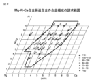
- FIG. 1 is a diagram showing a range of Al and Ca contents of a magnesium alloy according to a second embodiment of the present invention.
- FIG. 2 is a diagram showing a range of Al and Ca contents of the magnesium alloy used in the modified example of the second embodiment of the present invention.
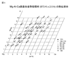
- FIG. 3 is a diagram showing the thermal conductivity of the magnesium alloy cast material of the plurality of samples of Example 1.
- 4 (a) to 4 (d) are IPF maps of the cast material of the Mg 85 Al 10 Ca 5 alloy of the sample of Example 1.
- FIG. 5 is a diagram showing the thermal conductivity of the cast heat-treated material of the magnesium alloy of the plurality of samples of Example 1.
- FIG. 6 is a TEM photograph and a SAED image of the cast material of the Mg 85 Al 10 Ca 5 alloy of the sample of Example 1.
- FIG. 7 is an SEM photograph obtained by observing the structure of the cast material of the Mg 85 Al 10 Ca 5 alloy of the sample of Example 1.
- FIG. 8 (a) is an SEM photograph in which the structure of the cast material of the Mg 85 Al 10 Ca 5 alloy of the sample of Example 1 was observed, and
- FIG. 8 (b) is the Mg 85 Al 10 Ca of the sample of Example 1. It is an SEM photograph which observed the structure of the cast heat-treated material of 5 alloys.
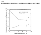
- FIG. 9 is a diagram showing the effect of the heat treatment time on the solute concentration in the ⁇ -Mg matrix in the ⁇ -Mg grains.
- FIG. 9 is a diagram showing the effect of the heat treatment time on the solute concentration in the ⁇ -Mg matrix in the ⁇ -Mg grains.
- FIG. 10A shows the result of XRD analysis of pure Mg
- FIG. 10B shows the result of XRD analysis of the cast material of Mg 85 Al 10 Ca 5 alloy of the sample of Example 1.
- FIG. 10 (c) is a diagram showing the results of XRD analysis of the cast heat-treated material of the Mg 85 Al 10 Ca 5 alloy of the sample of Example 1.
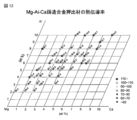
- FIG. 11 is a diagram showing the thermal conductivity of the extruded material after the casting heat treatment of the magnesium alloys of the plurality of samples of Example 1.
- FIG. 12 is a diagram showing the thermal conductivity of the extruded material after casting the magnesium alloys of the plurality of samples of Example 1.
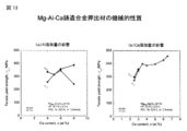
- 13 (a) and 13 (b) are diagrams showing the results of measuring the mechanical properties of the sample used in FIG.
- FIG. 15 is a diagram showing the thermal conductivity and yield strength of the chip solidified molded material of the Mg 99.98-3 x Al 2 x Ca x Mn 0.02 alloy of Example 2.
- FIG. 16 is a diagram showing the thermal conductivity and yield strength of the Mg 99.98-3 x Al 2 x Ca x Mn 0.02 rapid solidification solidified molding material of Example 3.
- FIG. 17 is a diagram showing a range of Al and Ca contents of the magnesium alloy used in the modified example of the second embodiment of the present invention.
- FIG. 18 is a diagram showing that the ignition temperature of the magnesium alloy obtained by adding Be or Yb to Mg-4Al-2Ca (atomic%) of Example 4 has improved.
- 19 (a) and 19 (b) show that a cast material of Mg 87.98 Al 8 Ca 4 Mn 0.02 alloy is heat-treated at a temperature of 623 K for 8 hours, and then extruded at an extrusion temperature of 523 K with an extrusion ratio of 10. It is a photograph which shows the structure of the extruded material which extruded at a speed of 2.5 mm / s.
- FIG. 20 shows the anisotropy of the thermal conductivity in the ED direction and the TD direction of the extruded material after heat treatment and the chip solidification molding material after heat treatment of the Mg 99.98-3 x Al 2x Ca x Mn 0.02 alloy of Example 2. It is a figure which shows.
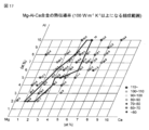
- FIG. 21 is a diagram showing a range of Al and Ca contents of the magnesium alloy according to the first embodiment of the present invention.
- FIG. 22 is a diagram showing a range of Al and Ca contents of the magnesium alloy used in the modified example of the first embodiment of the present invention.
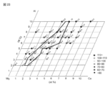
- FIG. 23 is a diagram showing a range of Al and Ca contents of an example in which the composition range of the magnesium alloy shown in FIG. 17 is further changed.
- FIG. 21 is a diagram showing a range of Al and Ca contents of the magnesium alloy according to the first embodiment of the present invention.
- FIG. 22 is a diagram showing a range of Al and Ca contents of the magnesium alloy used in the modified example of the first embodiment of the present invention.
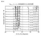
- FIG. 24 is a diagram showing the results of XRD analysis of the Mg 98-2 x Al x + 2 C x alloy cast material of the sample of Example 5.
- FIG. 25 is a diagram showing the results of XRD analysis of the heat-treated material obtained by heat-treating the Mg 98-2 x Al x + 2 C x alloy cast material of the sample of Example 5.
- FIG. 26 is a diagram showing the results of XRD analysis of the extruded material obtained by extruding the heat-treated material of the sample of Example 5.
- FIG. 27 is a diagram showing the relationship between the solute element concentration and the thermal conductivity of the ⁇ -Mg phase of the Mg—Al—Ca alloy of the sample of Example 6.
- FIG. 28 measures the mechanical properties (0.2% proof stress: ⁇ 0.2 , elongation: ⁇ ) of the extruded material sample (Mg 98-2 x Al x + 2 C x cast alloy heat-treated extruded material) used in FIG. It is a figure which shows the result of this.
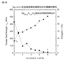
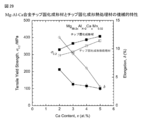
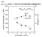
- FIG. 29 shows the mechanical properties of the chip solidified molding material of the Mg 97.98-2 x Al x + 2 Ca x Mn 0.02 alloy of the sample of Example 7 and the chip solidification molding heat treatment material obtained by heat-treating the chip solidification molding material. It is a figure which shows the result of having measured.
- FIG. 29 shows the mechanical properties of the chip solidified molding material of the Mg 97.98-2 x Al x + 2 Ca x Mn 0.02 alloy of the sample of Example 7 and the chip solidification molding heat treatment material obtained by heat-treating the chip solidification molding material. It is a figure which shows the result of having measured.
- FIG. 30 shows the results of measuring the mechanical properties of the quenching material of the Mg 97.98-2 x Al x + 2 Ca x Mn 0.02 alloy of the sample of Example 8 and the quenching heat-treated material obtained by heat-treating the quenching material. It is a figure.
- FIG. 31 is a diagram showing the results of a salt water immersion test on a quenching material of Mg 97.98-2 x Al x + 2 Ca x Mn 0.02 alloy of the sample of Example 9.
- FIG. 32 is a diagram showing the effect of the timing of heat treatment on the heat conduction characteristics when preparing the chip solidified molded material of Mg 90.98 Al 6 Ca 3 Mn 0.02 alloy of the sample of Example 10.
- FIG. 33 is a diagram showing the effect of the heat treatment conditions on the heat conduction characteristics of the Mg-5Al-3Ca-0.02Mn alloy of the sample of Example 11.
- the magnesium alloy according to one aspect of the present invention contains a atomic% of element A, b atomic% of element B, c atomic% of C element, d atomic% of D element, and the balance is Mg. And an alloy consisting of unavoidable impurities. Elements C and D are elements for improving characteristics.
- the A element content of a atomic% and the B element content of b atomic% are shown in (1) to (4) below according to the coordinates (a, b) with a on the horizontal axis and b on the vertical axis. It shall be within the range surrounded by the straight line.
- (1) a is in the range of the following formula 1a, it is a straight line of the following formula 1b.
- (Equation 1a) 0.5 ⁇ a ⁇ 4.83 (Equation 1b) b 1.5 (2)
- b is in the range of the following formula 2a, it is a straight line of the following formula 2b.
- the element A and the element B are elements that satisfy the following conditions 1 to 3.
- Condition 1 When the mixed enthalpy of Mg and element A is ⁇ H Mg ⁇ A , the following equation is satisfied. -4.5 (kJ / mol) ⁇ H Mg-A ⁇ 0 (kJ / mol) (Condition 2) When the mixed enthalpy of Mg and element B is ⁇ H Mg ⁇ B , the following equation is satisfied. -7.5 (kJ / mol) ⁇ H Mg-B ⁇ -5.5 (kJ / mol) (Condition 3) If the mixing enthalpy of A element and B element was [Delta] H A-B, satisfy the following equation.
- the element C is an element that satisfies the following condition 4. (Condition 4) the enthalpy of mixing of the A element and the element C and [Delta] H A-C, the enthalpy of mixing element B and the element C in the case of the [Delta] H B-C, satisfy the following equation. ⁇ H A-B ⁇ H A- C and ⁇ H A-B ⁇ H B- C
- the D element is an element that satisfies the following condition 5.
- the magnesium alloy contains X% of a compound composed of elements A and B (compound AB) in an area fraction, and X satisfies the following formula 41.
- Equation 41 0 ⁇ X ⁇ 10
- this magnesium alloy contains Y% of a compound composed of Mg and element A (Mg—A compound) in terms of area fraction, and Y satisfies the following formula 42. That is, it is preferable that the magnesium alloy does not contain a compound composed of Mg and element A.
- the magnesium alloy contains Z% of a compound composed of Mg and element B (Mg-B compound) in terms of area fraction, and Z may satisfy the following formula 43.
- the magnesium alloy contains W% of a compound composed of Mg, A element and B element (Mg-A compound) in terms of area fraction, and W may satisfy the following formula 44.
- the total content of X, Y, Z and W may satisfy the following formula 45.
- the above magnesium alloy is preferably having a thermal conductivity of 75 W / m ⁇ K or more.
- the above element A is preferably Al or Zn.
- the element B may be any of Ca, Ce and Y.
- the element C is preferably Mn or Zr, which is an element for improving corrosion resistance.
- the D element may be one or more kinds of elements such as RE (rare earth element), Si, Sr, Sn, Li, Zn, Ag, Be and Sc.
- RE rare earth element
- Si Si
- Sr Sn
- Li Zn
- Ag, Be and Sc The RE content may satisfy the following formula 51. (Equation 51) 0 ⁇ RE ⁇ 0.4 wt%
- the compound composed of the A element and the B element (AB compound) becomes the C15 type intermetallic compound phase (Al 2 Ca phase), and from Mg and the A element.
- Compound (Mg-A compound) becomes ⁇ phase (Mg 17 Al 12 compound) and the like, and compound composed of Mg and element B (Mg-B compound) becomes C14 type intermetallic compound phase (Mg 2 Ca phase).
- the compound (Mg—AB compound) composed of the A element and the B element becomes the C36 type intermetallic compound phase ((Mg, Al) 2 Ca phase).
- the Mg-A compound that inhibits the thermal conductivity while forming the Mg-B compound and the Mg-BA compound that increase the mechanical strength. Therefore, according to the conditions 1 and 2, it is possible to improve the thermal conductivity while increasing the mechanical strength.
- the " ⁇ H A-B ⁇ -11 (kJ / mol) " condition 3, likely to be formed is A-B compound by bonding element A and element B are dissolved in the alpha-Mg grains ..
- the AB compound is formed in the ⁇ -Mg crystal grains, so that the purity in the ⁇ -Mg crystal grains is increased and the thermal conductivity is improved.
- condition 3 the tendency of A-B compound is formed than Mg-B compound and Mg-B-A compounds is strengthened, alpha- The purity in the Mg crystal grains is also increased, and the thermal conductivity is improved.
- condition 4 ⁇ H A-B ⁇ H A- C and ⁇ H A-B ⁇ H B- C "
- condition 5 [Delta] H
- AB ⁇ H C-D the binding force between the A element and the C element, the B element and the C element, or the binding force between the C element and the D element becomes weaker than the binding force between the A element and the B element.
- Magnesium alloys satisfying conditions 1 to 3 include Mg-Zn-Ca alloys, Mg-Zn-Ce alloys, Mg-Zn-Y alloys, and the like, in addition to Mg-Al-Ca alloys.
- the mixed enthalpy of the above conditions 1 to 5 will be specifically described by taking the Mg—Al—Ca alloy as an example.
- an Mg-Ca compound for example, C14 type Mg 2 Ca compound
- Mg-Ca-Al compound for example, C36 type (Mg, Al) 2 Ca compound
- thermal conductivity is improved while forming an Mg-Ca compound (for example, C14 type Mg 2 Ca compound) and an Mg-Ca-Al compound (for example, C36 type (Mg, Al) 2 Ca compound) that enhance mechanical strength.
- an inhibitory Mg-Al compound for example, ⁇ phase (Mg 17 Al 12 compound), etc.
- the above magnesium alloy is a eutectic of an Mg-Ca compound (C14 type Mg 2 Ca compound) or an Mg-Al-Ca compound (C36 type (Mg, Al) 2 Ca compound) and an ⁇ -Mg phase.
- tissue may have a alpha-Mg grains containing Al-Ca compound (C15 type Al 2 Ca compound).
- Mn or RE element which is effective for corrosion resistance and high strength, is added to the above Mg-Al-Ca alloy, ⁇ H Al-Ca ⁇ H Al-Mn , ⁇ H Al-Ca ⁇ H Ca-Mn , ⁇ H Al.
- FIG. 1 is a diagram showing a range of Al and Ca contents of a magnesium alloy according to a second embodiment of the present invention.
- the composition range surrounded by a straight line shown in FIG. 1 is 75 W / m ⁇ K for any of a casting material, a casting heat treatment material, a cast plastic working material (for example, an extruded material and an extruded material after heat treatment) quenching material and a 3D laminated molding material. It is a range having the above thermal conductivity.
- the "casting material” is a casting material cast at a solidification rate of less than 1,000 K / s, and is a casting method such as mold casting, sand casting, semi-continuous casting, die casting, injection molding, and double roll. Includes castings made by casting.
- the "cast plastic working material” is an alloy material produced by extrusion, rolling, forging, drawing, and solidification molding of a chipping material, which is a cast material cast at a solidification rate of less than 1,000 K / s.
- the "quenching material” is a powder, ribbon or wire produced at a solidification rate of 1,000 to 1,000,000 K / s and a solidification molding material thereof, and the solidification molding is extrusion / rolling. ⁇ Perform by forging or hot pressing.
- the "3D laminated molding material” is a material obtained by 3D laminated molding of magnesium alloy powder, ribbon, wire, rod-shaped cast plastic working material or quenching material using an electron beam or a laser beam.
- the magnesium alloy according to this embodiment has the following composition range.
- This magnesium alloy does not contain Si and Sr.
- the reason why Si is not contained is that a compound is formed by the alloying element and Si, which affects the accuracy and mechanical properties of the alloy composition.
- the c atomic%, which is the content of Mn may satisfy the following formula 1, preferably the following formula 1'. (Equation 1) 0 ⁇ c ⁇ 0.1 (Equation 1') 0.01 ⁇ c ⁇ 0.05
- the reason for containing Mn is to improve the corrosion resistance of the magnesium alloy.
- the D element may have at least one of RE (rare earth element), Sn, Li, Zn, Ag, Be and Sc.
- RE rare earth element
- the d atomic% which is the content of the D element, should satisfy the following formula 2.
- the rare earth elements are Sc, Y, La, Ce, Pr, Nd, Pm, Sm, Eu, Gd, Tb, Dy, Ho, Er, Tm, Yb, and Lu.
- Equation 2 0 ⁇ d ⁇ 1
- the reason for containing the D element is to improve the ignition temperature and mechanical properties. This is because if the content of the D element exceeds 1 atomic%, good thermal conductivity will be impaired.
- the a atom is represented by the coordinates (b, a) in which a, which is the Al content (atomic%), is taken on the vertical axis and b, which is the Ca content (atomic%), is taken on the horizontal axis.
- the Al content of% and the Ca content of b atomic% may be within the range surrounded by the straight lines represented by the following (1) to (8). When (1) b is in the range of the following formula 1a, it is a straight line of the following formula 1b.
- the D element has at least one of RE (rare earth element) other than Yb, Sr, Sn, Li, Zn, Ag, Be and Sc, and contains at least one of Yb and Be, and the content of Yb is e. It is atomic% and the Be content is f.
- the e satisfies the following formula 18, and the f satisfies the following formula 19.
- (Equation 18) 0.01 ⁇ e ⁇ 1 (preferably 0.1 ⁇ e ⁇ 0.2)
- the following effects are obtained by containing at least one of Yb and Be.
- the ignition temperature of the magnesium alloy can be improved.
- the strength and ductility of the magnesium alloy can be improved.
- the high temperature strength of the magnesium alloy can be improved.
- the composition range of the magnesium alloy according to the present embodiment may be changed as follows. Only the points different from the composition range of the above magnesium alloy will be described.
- the D element has at least one of RE (rare earth element), Sr, Sn, Li, Zn, Ag, Be and Sc.
- RE rare earth element
- Sr rare earth element
- Sn Li
- Zn Li
- Ag, Be and Sc The cast plastic working material and the rapidly cooled solidified molded material produced with this alloy composition exhibit the following anisotropy in thermal conductivity. Therefore, by utilizing this, a cast plastic working material and a quenching solidification molded material having high thermal conductivity can be produced.
- the magnesium alloy of the cast plastic work material and the quenching solidification molding material has a first thermal conductivity of 75 W / m ⁇ K or more in the first direction and a second thermal conductivity in the second direction.
- the first thermal conductivity is ⁇ 1
- the second thermal conductivity is ⁇ 2
- ⁇ 1 and ⁇ 2 satisfy the following equation 20.
- the advantage of the cast plastic working material and the like is that the anisotropy of thermal conductivity can be controlled by controlling the texture. For example, in the case of an extruded material, the thermal conductivity in the extrusion direction becomes high.
- the 0.2% proof stress of the cast plastic working material or the like can be set to 200 MPa or more (preferably 250 MPa or more), and high ductility and high corrosion resistance can be expected.
- the composition range of the magnesium alloy according to the present embodiment may be changed as follows. Only the points different from the composition range of the above magnesium alloy will be described.
- the range of Al and Ca contents is the range surrounded by the straight line shown in FIG. 17, and the details are as follows.
- the range shown in FIG. 17 is a range in which the thermal conductivity of any of the cast material, the heat-treated material, the extruded material, and the extruded material after the heat treatment is 100 W / m ⁇ K or more.
- the Al content of a atomic% and b are based on the coordinates (b, a) with the Al content (atomic%) a on the vertical axis and the Ca content (atomic%) b on the horizontal axis.
- the Ca content of atomic% may be within the range surrounded by the straight lines represented by the following (1) to (10).
- (1) b is in the range of the following formula 1a, it is a straight line of the following formula 1b.
- (Equation 1a) 1 ⁇ b ⁇ 2 (Equation 1b) a 2 (2)
- b is in the range of the following formula 2a, it is a straight line of the following formula 2b.
- the range of Al and Ca contents is the range surrounded by the straight line shown in FIG. 23, and the details are as follows.
- the Al content of a atomic% and b are based on the coordinates (b, a) with the Al content (atomic%) a on the vertical axis and the Ca content (atomic%) b on the horizontal axis.
- the Ca content of atomic% may be within the range surrounded by the straight lines represented by the following (1) to (11).
- (1) b is in the range of the following formula 1a, it is a straight line of the following formula 1b.
- (Equation 1a) 1.5 ⁇ b ⁇ 2 (Equation 1b) a 2 (2)
- the first thermal conductivity is ⁇ 1
- the second thermal conductivity is ⁇ 2
- ⁇ 1 and ⁇ 2 satisfy the following equation 20.
- (Equation 20) 1 ⁇ ⁇ 1 / ⁇ 2 ⁇ 1.3
- the advantage of the cast plastic working material and the like is that the anisotropy of thermal conductivity can be controlled by controlling the texture. For example, in the case of an extruded material, the thermal conductivity in the extrusion direction becomes high. Further, the 0.2% proof stress of the cast plastic working material or the like can be set to 200 MPa or more (preferably 250 MPa or more), and high ductility and high corrosion resistance can be expected.
- the extruded material (HT-EX) after heat treatment is an extrusion ratio of 10 at an extrusion temperature of 523K after heat-treating a cast material of Mg 99.98-3x Al 2x Ca x Mn 0.02 alloy at a temperature of 623K for 8 hours.
- the chip molding material (HT-chip bonded ) is a cast material of Mg 99.98-3 x Al 2x C x Mn 0.02 alloy, which is heat-treated at a temperature of 673 K for 2.5 hours, and this heat treatment is performed. It is a chip molding material obtained by cutting a material to form a chip material and solidifying and molding the chip material by pressure molding. Then, the anisotropy of the thermal conductivity of each of the extruded material after heat treatment and the chip molding material after heat treatment was measured by the same method as in Example 1 described later.
- the ED direction is the extrusion direction.
- the TD direction is a right-angled direction (a direction perpendicular to the extrusion direction). According to FIG.
- the composition range of the magnesium alloy according to the present embodiment may be changed as follows. Only the points different from the composition range of the above magnesium alloy will be described. It is a magnesium alloy containing a atomic% of Al, b atomic% of Ca, c atomic% of Mn, d atomic% of D element, and the balance consisting of Mg and unavoidable impurities.
- the D element has at least one of RE (rare earth element), Sr, Sn, Li, Zn, Ag, Be and Sc.
- RE rare earth element
- the range of Al and Ca contents is the range surrounded by the straight line shown in FIG. 2, and the details are as follows.
- the Al content of a atomic% and b are based on the coordinates (b, a) with the Al content (atomic%) a on the vertical axis and the Ca content (atomic%) b on the horizontal axis.
- the Ca content of atomic% may be within the range surrounded by the straight lines represented by the following (1) to (9). When (1) b is in the range of the following formula 1a, it is a straight line of the following formula 1b.
- the range of Al and Ca contents is the range surrounded by the straight line shown in FIG.
- the thermal conductivity of the above magnesium alloy is 100 W / m ⁇ K or more.
- the composition range of the magnesium alloy described above can be combined with each modification.
- the composition range of the magnesium alloy is within the above-mentioned range, but impurities that do not affect the alloy properties may be contained.
- the magnesium alloy in the above composition range may contain unavoidable impurities.
- the magnesium alloy according to the present embodiment is an ⁇ -Mg phase and a C36 type intermetallic compound phase ((Mg, Al) 2 Ca phase), or an ⁇ -Mg phase and a C36 type intermetallic compound phase and a C15 type intermetallic compound phase. It has (Al 2 Ca phase) and contains 5% by volume or more and 40% by volume or less of the C36 type intermetallic compound phase. Further, this magnesium alloy may contain 5% by volume of a C14 type intermetallic compound phase (Mg 2 Ca phase).
- the ⁇ -Mg phase means that a single crystal ⁇ -Mg and a polycrystalline ⁇ -Mg are included.
- the magnesium alloy according to the present embodiment preferably has a plurality of ⁇ -Mg particles and a eutectic lamellar structure of the ⁇ -Mg phase and the C36 type intermetallic compound phase, and the plurality of ⁇ -Mg particles are interspersed with each other. May be connected by the eutectic lamella.
- the ⁇ -Mg particles are networked via the ⁇ -Mg phase of the eutectic lamella. Since ⁇ -Mg has a higher thermal conductivity than the intermetallic compound, the thermal conductivity of the magnesium alloy can be improved. These constituent phases are produced in the casting material and the casting heat treatment material. Further, the ⁇ Mg grains are considered to be single crystal ⁇ -Mg and are considered to be primary crystal ⁇ Mg grains. Al is contained in 0.5 atomic% or more and 2.5 atomic% or less (preferably 0.7 atomic% or more and 2.0 atomic% or less) in the ⁇ -Mg matrix in the ⁇ -Mg granules, and Ca is contained.
- the content is more than 0 atomic% and 1.0 atomic% or less. Further, it is preferable that the half-value width of the X-ray diffraction peak of the ⁇ -Mg phase is less than 1.5 times the half-value width of the X-ray diffraction peak of pure Mg. Further, the half-value width of the X-ray diffraction peak of the ⁇ -Mg phase is half of the X-ray diffraction peak of the ⁇ -Mg phase of the cast material immediately after being manufactured by the casting method with the alloy compositions shown in FIGS. 1, 2 and 17. It is preferable that the price range is reduced by 10% or more. It is considered that this makes it possible to improve the thermal conductivity of the ⁇ -Mg phase.
- the linear compound or the plate-like compound is precipitated in the ⁇ -Mg particles.
- the linear compound or plate-like compound is preferably a C15 type intermetallic compound phase. Since the C15 type intermetallic compound phase is an Al 2 Ca phase, the C15 type intermetallic compound phase is precipitated in the ⁇ -Mg granules to contain Al and Ca in the ⁇ -Mg matrix of the ⁇ -Mg granules. The amount can be reduced. As a result, the Mg concentration in the ⁇ -Mg granules can be increased, which is considered to be useful for improving the thermal conductivity.
- the half-value width of the X-ray diffraction peak of the above C36 type intermetallic compound is the X-ray diffraction peak of the C36 type intermetallic compound of the cast material immediately after being produced by the casting method with the alloy compositions shown in FIGS. 1, 2 and 17. It is preferable that the value is reduced by 10% or more with respect to the half price range of. This is because the concentration of solute elements in the ⁇ -Mg phase has decreased, and as a result, the thermal conductivity is considered to have improved.
- the magnesium alloy according to this embodiment is surrounded by the straight lines shown in FIGS. 1 or 2. Although the above composition ranges are used, the composition range may be further limited to the following.
- a and b may be a composition range with a limitation satisfying any of the following formulas 5 and 6, formulas 7 and 8, formulas 9 and 10, and formulas 11 and 12. .. (Equation 5) 2.0 ⁇ a ⁇ 12.5 (Equation 6) 1.0 ⁇ b ⁇ 3 (Equation 7) 2.0 ⁇ a ⁇ 12.5 (Equation 8) 7 ⁇ b ⁇ 7.5 (Equation 9) 2.0 ⁇ a ⁇ 4.5 (Equation 10) 1.0 ⁇ b ⁇ 7.5 (Equation 11) 12.0 ⁇ a ⁇ 12.5 (Equation 12) 1.0 ⁇ b ⁇ 7.5 Further, a and b may be composition ranges that satisfy the following formulas 13 and 14, and also satisfy the following formulas 15 or 16.
- a magnesium alloy having a thermal conductivity of 75 W / m ⁇ K or more and a high specific strength can be obtained.
- This high specific strength means that it has a specific strength equal to or higher than that of the commercial magnesium alloy or the high thermal conductivity aluminum alloy ACD12.
- Mg—Al—Ca alloy it is also applied to a material in which particles or fibers of carbon, ceramics, metal or an intermetallic compound and the Mg—Al—Ca alloy of the present embodiment are composited. .. Specifically, it can also be applied to a composite material in which at least one of particles and fibers is composited with the magnesium alloy of the present embodiment, and the particles are at least carbon particles, ceramic particles, metal particles and intermetal compound particles.
- the fiber is at least one of carbon fiber, ceramic fiber and metal fiber.
- the magnesium alloy in the composition range according to the first or second embodiment is melted at a predetermined temperature in a flameproof gas atmosphere, and then cast at a solidification rate of less than 1000 K / sec.
- the magnesium alloy ingot after casting is cut into a predetermined shape. As a result, a cast material is produced.
- the ⁇ -Mg phase, the C15 type intermetallic compound phase (Al 2 Ca phase), and the C14 type intermetallic compound phase (Mg 2 Ca) when the element A is Al and the element B is Ca, the ⁇ -Mg phase, the C15 type intermetallic compound phase (Al 2 Ca phase), and the C14 type intermetallic compound phase (Mg 2 Ca), Alternatively, the ⁇ -Mg phase, the C15 type intermetallic compound phase, the C14 type intermetallic compound phase, and the C36 type intermetallic compound phase ((Mg, Al) 2 Ca phase), or the ⁇ -Mg phase and the C36 type intermetallic compound.
- a phase, or an ⁇ -Mg phase, a C36 type intermetallic compound phase, and a C15 type intermetallic compound phase is contained in an amount of 5% by volume or more and 40% by volume or less.
- Al and Ca existing in the ⁇ -Mg crystal grains become a C15 type Al 2 Ca compound, and the purity of ⁇ -Mg in the ⁇ -Mg crystal grains is increased.
- the above-mentioned cast material is subjected to 0 hours or more and 200 hours or less (preferably 100 hours or less, more preferably 0.5 hours or more and 24 hours) at a temperature of 200 ° C. or more and 510 ° C.
- the A element and the B element existing in the ⁇ -Mg crystal grain become a compound composed of the A element and the B element (for example, a C15 type Al 2 Ca compound), and the ⁇ -Mg crystal grain has a compound (for example, C15 type Al 2 Ca compound).
- a cast heat-treated material having an increased content of an AB compound for example, a C15 type Al 2 Ca compound
- the thermal conductivity of this cast heat-treated material is preferably 100 W / K ⁇ m or more.
- the casting heat treatment material may have an ⁇ -Mg phase, a C15 type intermetallic compound phase, and a C14 type intermetallic compound phase, and may have the same compound as the above-mentioned casting material.
- plastic working is performed on the above-mentioned cast heat-treated material.
- This plastic working includes extrusion, rolling, forging, drawing and straining.
- the giant strain machining includes ECAE (equal-channel-angular-extrusion) machining.
- Extrusion processing conditions are, for example, an extrusion temperature of 250 ° C. or higher and 500 ° C. or lower, and a cross-sectional reduction rate of 5% or higher due to extrusion.
- the ⁇ -Mg phase, the C15 type intermetallic compound phase, and the C14 type intermetallic compound phase are present even after the plastic processing, and that the compound is similar to that of the casting material described above.
- the cast heat-treated material is subjected to plastic working, but the above-mentioned cast material may be subjected to plastic working, or the above-mentioned heat treatment may be carried out after the plastic working. Even after this heat treatment, it is preferable to have the same compound as the above-mentioned cast material.
- each of the above-mentioned cast material, cast heat-treated material, and plastically processed plastic processed material has a C15 type intermetallic compound phase, and the C14 type intermetallic compound phase (Mg 2 Ca phase) is 5% by volume. It should be contained. Further, each of the above-mentioned cast material and cast heat-treated material has an eutectic structure of an Mg-B compound or an Mg-AB compound and an ⁇ -Mg phase, and ⁇ -Mg grains containing an AB compound.
- it has a eutectic lamellar structure of a plurality of ⁇ -Mg grains and an ⁇ -Mg phase and a C36 type intermetallic compound phase, and the eutectic lamellas between the plurality of ⁇ -Mg grains are present. They are connected by a structure, and the ⁇ -Mg grains are networked via the ⁇ -Mg phase of the eutectic lamellar structure.
- Al is contained in 0.5 atomic% or more and 2.5 atomic% or less (preferably 0.7 atomic% or more and 2.0 atomic% or less) in the ⁇ -Mg matrix in the above ⁇ -Mg grains.
- Ca is contained in an amount of more than 0 atomic% and 1.0 atomic% or less. It is preferable that a linear compound or a plate-like compound is precipitated in the above ⁇ -Mg grains, and the linear compound or the plate-like compound is a C15 type intermetallic compound phase.
- 19 (a) and 19 (b) show that a cast material of Mg 87.98 Al 8 Ca 4 Mn 0.02 alloy is heat-treated at a temperature of 623 K for 8 hours, and then extruded at an extrusion temperature of 523 K with an extrusion ratio of 10. It is a photograph which shows the structure of the extruded material which extruded at a speed of 2.5 mm / s. As shown in FIG.
- the half-value width of the X-ray diffraction peak of the ⁇ -Mg phase of each of the above-mentioned cast material and the cast heat-treated material is preferably less than 1.5 times the half-value width of the X-ray diffraction peak of pure Mg. Further, the half-value width of the X-ray diffraction peak of the ⁇ -Mg phase of the above-mentioned cast heat-treated material is reduced by 10% or more with respect to the half-value width of the X-ray diffraction peak of the ⁇ -Mg phase of the cast material immediately after casting. It is good.
- the half-value width of the X-ray diffraction peak of the C36-type intermetallic compound of the above-mentioned casting heat-treated material is reduced by 10% or more with respect to the half-value width of the X-ray diffraction peak of the C36-type intermetallic compound of the casting material immediately after casting. It is good to have.
- each of the above-mentioned casting material, casting heat treatment material and plastic working material has a thermal conductivity of 75 W / m ⁇ K or more and a high specific strength.
- ⁇ Casting insert solidification> A cast material is produced by the same method as the above-mentioned casting method.
- the cast material is machined to form a chip material having a size of, for example, 1 to 2 mm.
- the solidified molded material is formed by solidifying and molding this chip material at room temperature by pressure molding.
- the solidified molded material may be subjected to plastic working, or the above heat treatment may be carried out after the plastic working. Further, the cast material may be subjected to the same heat treatment as the above-mentioned casting method before or after the chip material is formed. Further, the chip material or the solidified molded material may be subjected to the same heat treatment as the above-mentioned casting method before or after the solidified molded material is formed.
- the thermal conductivity of the solidified molded material after this heat treatment is preferably 100 W / K ⁇ m or more.
- the above-mentioned chip material, the heat-treated chip heat-treated material, the heat-treated material obtained by heat-treating the chip material, and the solidified molding material may each have a C15 type intermetallic compound phase, and a C14 type intermetallic compound phase may be used. It is preferable to contain 5% by volume. Further, the above-mentioned chip material, the heat-treated chip heat-treated material, the heat-treated material obtained by heat-treating the chip material, and the solidified molding material are each composed of Mg-B compound or Mg-AB compound and ⁇ -Mg phase. It is preferable to have a eutectic structure of the above and ⁇ -Mg particles containing an AB compound.
- a eutectic lamella of a plurality of ⁇ -Mg particles and an ⁇ -Mg phase and a C36 type intermetallic compound phase It has a structure, and a plurality of ⁇ -Mg grains are connected to each other by a eutectic lamella structure, and the ⁇ -Mg grains are networked via the ⁇ -Mg phase of the eutectic lamella structure.
- Al is contained in 0.5 atomic% or more and 2.5 atomic% or less (preferably 0.7 atomic% or more and 2.0 atomic% or less) in the ⁇ -Mg matrix in the above ⁇ -Mg grains.
- Ca is contained in an amount of more than 0 atomic% and 1.0 atomic% or less. It is preferable that a linear compound or a plate-like compound is precipitated in the above ⁇ -Mg grains, and the linear compound or the plate-like compound is a C15 type intermetallic compound phase.
- the half-value width of the X-ray diffraction peak of the ⁇ -Mg phase of each of the above-mentioned chip material, the heat-treated chip heat-treated material, and the heat-treated material of the chip material is the half-value width of the X-ray diffraction peak of pure Mg. It is good that it is less than 1.5 times.
- the half-value width of the X-ray diffraction peak of the ⁇ -Mg phase of the chip heat-treated material subjected to the above heat treatment is 10% of the half-value width of the X-ray diffraction peak of the ⁇ -Mg phase of the chip material immediately after chipping. It is good that the number has decreased.
- the half-value width of the X-ray diffraction peak of the C36-type intermetallic compound of the chip heat-treated material subjected to the above heat treatment is the half-value width of the X-ray diffraction peak of the C36-type intermetallic compound of the chip material immediately after chipping. It is good that it is reduced by 10% or more.
- the above-mentioned chip material, the heat-treated chip heat-treated material, the heat-treated material obtained by heat-treating the chip material, and the solidified molding material each have a thermal conductivity of 75 W / m ⁇ K or more and a high specific strength.
- the magnesium alloy having a composition range according to the first or second embodiment is heated and melted at a predetermined temperature in a flameproof gas atmosphere, and the molten magnesium alloy is injected into a mold to be cooled and solidified. By doing so, an injection molding material is produced.
- the cooling speed is preferably 1000 K / sec or less.
- Al and Ca existing in the ⁇ -Mg crystal grains become a C15 type Al 2 Ca compound, and the purity of ⁇ -Mg in the ⁇ -Mg crystal grains is increased.
- a compound for example, C15 type Al
- the A element and the B element existing in the ⁇ -Mg crystal grains are composed of the A element and the B element (for example, C15 type Al). 2 Ca compound) to form an injection-molded heat-treated material in which the content of AB compound (for example, C15 type Al 2 Ca compound) in ⁇ -Mg crystal grains is increased.
- each of the above-mentioned injection molding material and injection molding heat treatment material may have a C15 type intermetallic compound phase, and may contain 5% by volume of a C14 type intermetallic compound phase. Further, each of the above-mentioned injection molding material and injection molding heat treatment material contains the eutectic structure of the Mg-B compound or the Mg-AB compound and the ⁇ -Mg phase, and the ⁇ -Mg containing the AB compound.
- grains for example, having a plurality of ⁇ -Mg grains and a eutectic lamellar structure of an ⁇ -Mg phase and a C36 type intermetallic compound phase, and the plurality of ⁇ -Mg grains are coexisting with each other. They are connected by a crystalline lamellar structure, and the ⁇ -Mg grains are networked via the ⁇ -Mg phase of the eutectic lamellar structure.
- Al is contained in 0.5 atomic% or more and 2.5 atomic% or less (preferably 0.7 atomic% or more and 2.0 atomic% or less) in the ⁇ -Mg matrix in the above ⁇ -Mg grains.
- the half width of the X-ray diffraction peak of the ⁇ -Mg phase of each of the above-mentioned injection molding material and injection molding heat treatment material is preferably less than 1.5 times the half width of the X-ray diffraction peak of pure Mg.
- the half-value width of the X-ray diffraction peak of the ⁇ -Mg phase of the injection-molded heat-treated material is reduced by 10% or more with respect to the half-value width of the X-ray diffraction peak of the ⁇ -Mg phase of the injection-molded material immediately after injection molding. It is good to do it.
- the half-value width of the X-ray diffraction peak of the C36-type intermetallic compound of the injection-molded heat-treated material is 10% of the half-value width of the X-ray diffraction peak of the C36-type intermetallic compound of the injection-molded material immediately after injection molding. It is good that the number has decreased.
- each of the above-mentioned injection-molded material and injection-molded heat-treated material has a thermal conductivity of 75 W / m ⁇ K or more and a high specific strength.
- Die casting method> A die-cast material is produced by heating and melting a magnesium alloy having a composition range according to the first or second embodiment at a predetermined temperature in a flameproof gas atmosphere, and press-fitting the molten magnesium alloy into a mold. .. The cooling rate at this time is preferably less than 1000 K / sec.
- the die casting method is a casting method for mass-producing castings with high dimensional accuracy in a short time.
- the above-mentioned die cast material has an ⁇ -Mg phase, a C15 type intermetallic compound phase (Al 2 Ca phase), and a C14 type intermetallic compound phase (Mg 2 Ca). Or, ⁇ -Mg phase, C15 type intermetallic compound phase, C14 type intermetallic compound phase and C36 type intermetallic compound phase ((Mg, Al) 2 Ca phase), or ⁇ -Mg phase and C36 type intermetallic phase.
- a compound phase, or an ⁇ -Mg phase, a C36 type intermetallic compound phase, and a C15 type intermetallic compound phase it is preferable to have a compound phase, or an ⁇ -Mg phase, a C36 type intermetallic compound phase, and a C15 type intermetallic compound phase, and the C36 type intermetallic compound phase is contained in an amount of 5% by volume or more and 40% by volume or less. Further, in this die casting material, Al and Ca existing in the ⁇ -Mg crystal grains become a C15 type Al 2 Ca compound, and the purity of ⁇ -Mg in the ⁇ -Mg crystal grains is increased.
- a compound for example, C15 type Al 2 in which the A element and the B element existing in the ⁇ -Mg crystal grains are composed of the A element and the B element (for example, C15 type Al 2) Ca compound) to form a die-cast heat-treated material in which the content of AB compound (for example, C15 type Al 2 Ca compound) in ⁇ -Mg crystal grains is increased.
- the thermal conductivity of this die-cast heat-treated material is preferably 100 W / K ⁇ m or more.
- each of the above-mentioned die-casting material and die-casting heat-treated material may have a C15-type intermetallic compound phase, and may contain 5% by volume of a C14-type intermetallic compound phase. Further, each of the above-mentioned die-casting material and die-casting heat-treated material has an Mg-B compound or a eutectic structure of an Mg-AB compound and an ⁇ -Mg phase, and ⁇ -Mg grains containing an AB compound.
- the eutectic lamella structure of a plurality of ⁇ -Mg grains and an ⁇ -Mg phase and a C36 type intermetallic compound phase, and the eutectic lamellas are between the plurality of ⁇ -Mg grains. They are connected by a structure, and the ⁇ -Mg grains are networked via the ⁇ -Mg phase of the eutectic lamella structure.
- Al is contained in 0.5 atomic% or more and 2.5 atomic% or less (preferably 0.7 atomic% or more and 2.0 atomic% or less) in the ⁇ -Mg matrix in the above ⁇ -Mg grains.
- the half-value width of the X-ray diffraction peak of the ⁇ -Mg phase of each of the above-mentioned die-casting material and the die-casting heat-treated material is preferably less than 1.5 times the half-value width of the X-ray diffraction peak of pure Mg.
- the half-value width of the X-ray diffraction peak of the ⁇ -Mg phase of the die-casting heat-treated material is reduced by 10% or more with respect to the half-value width of the X-ray diffraction peak of the ⁇ -Mg phase of the die-casting material immediately after die casting. It is good. Further, the half-value width of the X-ray diffraction peak of the C36-type intermetallic compound of the die-cast heat-treated material is reduced by 10% or more with respect to the half-value width of the X-ray diffraction peak of the C36-type intermetallic compound of the die-cast material immediately after die casting. It is good to have.
- each of the above-mentioned die-casting material and die-casting heat-treated material has a thermal conductivity of 75 W / m ⁇ K or more and a high specific strength.
- ⁇ Quenching method> The magnesium alloy in the composition range according to the first or second embodiment is melted at a predetermined temperature in a flameproof gas atmosphere, and the molten metal of the magnesium alloy is melted at a solidification rate of 1,000 to 1,000,000 K / s. Quenching and solidifying to prepare a quenching material (powder, ribbon, wire).
- the quenching material may be, for example, a powder prepared by the RS-P / M method (or flakes, strips or thin wires prepared by the RS-P / M method, or thin wires prepared by the molten metal extraction method).
- the ⁇ -Mg phase, the C15 type intermetallic compound phase (Al 2 Ca phase), and the C14 type intermetallic compound phase (Mg 2 Ca) Or, ⁇ -Mg phase, C15 type intermetallic compound phase, C14 type intermetallic compound phase and C36 type intermetallic compound phase ((Mg, Al) 2 Ca phase), or ⁇ -Mg phase and C36 type intermetallic phase.
- a compound phase, or an ⁇ -Mg phase, a C36 type intermetallic compound phase, and a C15 type intermetallic compound phase it is preferable to have a compound phase, or an ⁇ -Mg phase, a C36 type intermetallic compound phase, and a C15 type intermetallic compound phase, and the C36 type intermetallic compound phase is contained in an amount of 5% by volume or more and 40% by volume or less.
- Al and Ca existing in the ⁇ -Mg crystal grains become a C15 type Al 2 Ca compound, and the purity of ⁇ -Mg in the ⁇ -Mg crystal grains is increased.
- a compound in which the A element and the B element existing in the ⁇ -Mg crystal grains are composed of the A element and the B element for example, C15 type Al 2).
- the thermal conductivity of this quenching heat-treated material is preferably 100 W / K ⁇ m or more.
- the quenching heat treatment material may have an ⁇ -Mg phase, a C15 type intermetallic compound phase, and a C14 type intermetallic compound phase, and may have the same compound as the casting material described above.
- the solidified molded material is formed by solidifying and molding the above-mentioned quenching heat-treated material by extrusion, rolling, forging, hot pressing, or the like.
- the quenching heat-treated material is solidified and molded, but the solidified molding material may be formed by solidifying and molding the quenching material before the heat treatment, or the solidified molding material is subjected to the above heat treatment. You may. Further, the solidified molded material may be subjected to plastic working, or the above heat treatment may be carried out after the plastic working without performing the heat treatment before the solidification molding.
- each of the above-mentioned quenching material, quenching heat treatment material, and solidifying molding material may have a C15 type intermetallic compound phase, and may contain 5% by volume of a C14 type intermetallic compound phase.
- each of the above-mentioned quenching material, quenching heat treatment material and solidified molding material has a thermal conductivity of 75 W / m ⁇ K or more and a high specific strength.
- the magnesium alloy according to each of the first to third embodiments is preferably applied to a component requiring thermal conductivity performance having a thermal conductivity of 75 W / m ⁇ K or more or 100 W / m ⁇ K. be.
- FIG. 3 is a diagram showing the thermal conductivity of the magnesium alloy cast material of the plurality of samples of Example 1.
- the plurality of samples are magnesium alloys containing Al and Ca having the composition shown in FIG. 3, with the balance being Mg and unavoidable impurities.
- a sample magnesium alloy ingot having the composition shown in FIG. 3 was melted in an argon atmosphere using a high-frequency melting furnace, and the ingot was cut into a shape of ⁇ 32 ⁇ 70 mm to prepare a cast material.
- the results of measuring the thermal conductivity of these cast materials are shown in FIG.
- the method for measuring the thermal conductivity is as follows. Process the sample to ⁇ 5 mm ⁇ 1-3 mm or 5 ⁇ 5 ⁇ 1-3 mm 3.
- the surface of the sample is blackened with a dry carbon spray. After the blackening treatment, the weight is measured again, and then the thermal diffusivity of the sample is measured by using a laser flash method. The product of the obtained thermal diffusivity, the specific gravity of the sample, and the specific heat capacity is the thermal conductivity.
- an IPF map by EBSD was obtained for the cast material of Mg 85 Al 10 Ca 5 alloy of the sample of Example 1. The results are shown in FIGS. 4 (a) to 4 (d).
- the IPF map is an inverse pole map crystal orientation map by EBSD (Electron Backscatter Diffraction Method).
- FIG. 4 (a) to 4 (d) are IPF maps of the cast material of the Mg 85 Al 10 Ca 5 alloy of the sample of Example 1, and FIG. 4 (a) is an image quality (IQ value) map.
- 4 (b) is an IPF map showing the ⁇ -Mg phase
- FIG. 4 (c) is an IPF map showing the C36 type intermetallic compound phase ((Mg, Al) 2 Ca phase)
- FIG. 4 (d) Is an IPF map showing a C14 type intermetallic compound phase (Mg 2 Ca phase).
- the cast material of the sample of Example 1 having the composition shown in FIG. 3 was heat-treated at a temperature of 673 K for 2.5 hours to form a cast heat-treated material.
- FIG. 6 is a TEM (Transmission Electron Microscope) photograph and a SAED (Selected area electron diffraction) image of a cast material of the Mg 85 Al 10 Ca 5 alloy of the sample of Example 1. As shown in FIG. 6, it was confirmed that a C15 type intermetallic compound phase was formed in this cast material.
- FIG. 7 is an SEM photograph obtained by observing the structure of the cast material of the Mg 85 Al 10 Ca 5 alloy of the above sample.
- This cast material has a plurality of ⁇ -Mg grains in a black portion and a eutectic lamellar structure of an ⁇ -Mg phase and a C36 type intermetallic compound phase, and the eutectic lamellar structure of a plurality of ⁇ -Mg grains. They are connected to each other. Therefore, it was confirmed that the ⁇ -Mg grains were networked via the ⁇ -Mg phase of the eutectic lamellar structure.
- FIG. 8 (a) is an SEM photograph obtained by observing the structure of the cast material of the Mg 85 Al 10 Ca 5 alloy of the sample of Example 1
- FIG. 8 (b) is the Mg 85 Al of the sample of Example 1.
- each of the cast material shown in FIG. 8 (a) and the cast heat-treated material shown in FIG. 8 (b) has a structure similar to that of the cast material shown in FIG. 7. That is, it has a plurality of ⁇ -Mg grains and a eutectic lamellar structure of an ⁇ -Mg phase and a C36 type intermetallic compound phase, and the eutectic lamellar structure connects the plurality of ⁇ -Mg grains to each other. There is.
- a linear compound or a plate-like compound is precipitated in the ⁇ -Mg particles of the cast heat-treated material shown in FIG. 8 (b), and the linear compound or the plate-like compound is a C15 type intermetallic compound phase.
- the C15 type intermetallic compound phase Al 2 Ca phase
- FIG. 8 it can be seen that the C15 type intermetallic compound phase (Al 2 Ca phase) is precipitated in the ⁇ -Mg particles by the heat treatment. It is considered that this reduces the total content of Al and Ca in the ⁇ -Mg matrix in the ⁇ -Mg grains and improves the thermal conductivity of the ⁇ -Mg grains.
- FIG. 9 is a diagram showing the effect of the heat treatment time on the solute concentration in the ⁇ -Mg matrix in the ⁇ -Mg grains, and is a Mg-8Al-4Ca-0.02Mn alloy (atomic%) of the sample of Example 1. ) Is heat-treated at a temperature of 623 K, and shows the relationship between the heat treatment time and the Al concentration and Ca concentration in the ⁇ -Mg matrix. As shown in FIG. 9, it can be seen that the Al concentration decreases as the heat treatment time increases. However, it was confirmed that the Ca concentration increased slightly, but the total content of Al and Ca decreased. From this, it can be said that the thermal conductivity of ⁇ -Mg particles is improved.
- FIG. 9 is a diagram showing the effect of the heat treatment time on the solute concentration in the ⁇ -Mg matrix in the ⁇ -Mg grains, and is a Mg-8Al-4Ca-0.02Mn alloy (atomic%) of the sample of Example 1. ) Is heat-treated at a temperature of 623 K,
- FIG. 10 (a) is a diagram showing the results of X-ray diffraction (XRD: X-Ray Diffraction) analysis of pure Mg
- FIG. 10 (b) is a diagram showing Mg 85 Al 10 Ca of the sample of Example 1.
- 5 is a graph showing the results of XRD analysis of the cast material of the alloy
- FIG. 10 (c) the results of XRD analysis of the cast heat-treated for Mg 85 Al 10 Ca 5 alloy samples of example 1 It is a figure which shows.
- the full width at half maximum (0.12) of the X-ray diffraction peak of the ⁇ -Mg phase of the cast material shown in FIG. 10 (b) is the full width at half maximum (0.06) of the X-ray diffraction peak of pure Mg shown in FIG.
- the half width (0.08) of the X-ray diffraction peak of the ⁇ -Mg phase of the cast heat-treated material shown in FIG. 10 (c) is the X-ray diffraction of the ⁇ -Mg phase of the cast material shown in FIG. 10 (b). It was confirmed that the peak width was reduced by 10% or more with respect to the half width (0.12).
- the half-value width (0.12) of the X-ray diffraction peak of the C36-type intermetallic compound of the cast heat-treated material shown in FIG. 10 (c) is the X of the C36-type intermetallic compound of the cast material shown in FIG. 10 (b).
- the half-value width of the peak appearing in the XRD pattern increases or decreases depending on the concentration of solute elements and strain. It is considered that when the cast material of the Mg 85 Al 10 Ca 5 alloy is heat-treated, the acicular compound is precipitated, so that the concentration of the solute element in the ⁇ -Mg phase is diluted and the half price range is reduced. This is also in agreement with the result of the above XRD measurement. In addition, the heat treatment reduces the concentration of solute elements in the ⁇ -Mg phase, which is consistent with the result of increased thermal conductivity.
- FIG. 11 is a diagram showing the thermal conductivity of the extruded material after the casting heat treatment of the magnesium alloys of the plurality of samples of Example 1.
- the method for measuring the thermal conductivity is the same as the method described above.
- FIG. 12 is a diagram showing the thermal conductivity of the extruded material after casting the magnesium alloys of the plurality of samples of Example 1. That is, the extruded material was formed by extruding the cast material without performing heat treatment after producing the cast material of a plurality of samples of Example 1.
- the extrusion conditions at this time are an extrusion ratio of 10, an extrusion temperature of 523 K, and an extrusion speed of 2.5 mm / s.
- the results of measuring the thermal conductivity of these extruded materials are shown in FIG.
- the method for measuring the thermal conductivity is the same as the method described above.
- the composition range shown in FIGS. 1 and 2 is based on the measurement results of FIGS. 3, 5, 11 and 12.
- FIG. 13 shows the mechanical properties (0.2% proof stress: ⁇ 0.2 ) of the sample used in FIG. 11 (extruded material after casting heat treatment) and the sample used in FIG. 12 (extruded material after casting).
- FIG. 13 (a) is a diagram showing the effect of the amount of Al added to the Mg 97-x Al x Ca 3 alloy
- FIG. 13 (b) shows the effect of the Mg 94-x Al 6 Ca x alloy. It is a figure which shows the influence of the Ca addition amount. As shown in FIG.
- the 0.2% strength of the extruded material after the casting heat treatment is about 260 MPa for the Mg 93 Al 4 Ca 3 alloy, about 320 MPa for the Mg 92 Al 5 Ca 3 alloy, and Mg 91 Al 6
- the Ca 3 alloy was about 345 MPa
- the Mg 89 Al 8 Ca 3 alloy was about 240 MPa.
- the 0.2% proof stress of the extruded material after casting is about 340 MPa for the Mg 93 Al 4 Ca 3 alloy, about 315 MPa for the Mg 92 Al 5 Ca 3 alloy, about 360 MPa for the Mg 91 Al 6 Ca 3 alloy, and Mg 89.
- the Al 8 Ca 3 alloy was about 390 MPa. As shown in FIG.
- the 0.2% strength of the extruded material after the casting heat treatment is about 275 MPa for the Mg 91.5 Al 6 Ca 2.5 alloy and about 350 MPa for the Mg 91 Al 6 Ca 3 alloy.
- Mg 90.5 Al 6 Ca 3.5 alloy is about 400 MPa
- Mg 90 Al 6 Ca 4 alloy is about 390 MPa
- Mg 89 Al 6 Ca 5 alloy is about 400 MPa
- Mg 88 Al 6 Ca 6 alloy is about 425 MPa
- the amount of the .5 l 6 Ca 6.5 alloy was about 460 MPa.
- the 0.2% proof stress of the extruded material after casting was about 300 MPa for the Mg 91.5 Al 6 Ca 2.5 alloy and about 360 MPa for the Mg 91 Al 6 Ca 3 alloy. According to FIGS.
- FIG. 14 shows the mechanical properties (0.2% proof stress: ⁇ 0.2 ) of the sample used in FIG. 11 (extruded material after casting heat treatment) and the sample used in FIG. 12 (extruded material after casting).
- FIG. 14 (a) is a diagram showing the effect of the amount of Ca added to the Mg 100-3 x Al 2 x Ca x alloy
- FIG. 13 (b) shows the effect of the Mg 98-2 x Al x + 2 Ca x alloy. It is a figure which shows the influence of the Ca addition amount. As shown in FIG.
- the 0.2% strength of the extruded material after the casting heat treatment is about 340 MPa for the Mg 97 Al 2 Ca 1 alloy, about 345 MPa for the Mg 94 Al 4 Ca 2 alloy, and Mg 92.5.
- the Al 5 Ca 2.5 alloy was about 340 MPa
- the Mg 89.5 Al 7 Ca 3.5 alloy was about 345 MPa
- the Mg 88 Al 8 Ca 4 alloy was about 350 MPa
- the Mg 85 Al 10 Ca 5 alloy was about 400 MPa. ..
- the 0.2% strength of the extruded material after casting is about 320 MPa for the Mg 97 Al 2 Ca 1 alloy, about 350 MPa for the Mg 94 Al 4 Ca 2 alloy, and 355 MPa for the Mg 92.5 Al 5 Ca 2.5 alloy.
- the Mg 89.5 Al 7 Ca 3.5 alloy was about 360 MPa
- the Mg 88 Al 8 Ca 4 alloy was about 340 MPa
- the Mg 85 Al 10 Ca 5 alloy was about 395 MPa.
- the 0.2% strength of the extruded material after the casting heat treatment is about 170 MPa for the Mg 98 Al 2 alloy, about 275 MPa for the Mg 96 Al 3 Ca 1 alloy, and Mg 94 Al 4 Ca 2 Alloy is about 325 MPa
- Mg 92 Al 5 Ca 3 alloy is about 320 MPa
- Mg 90 Al 6 Ca 4 alloy is about 390 MPa
- Mg 86 Al 8 Ca 6 alloy is about 430 MPa
- Mg 84 Al 9 Ca 7 alloy is about 450 MPa
- Mg The 82 Al 10 Ca 8 alloy was about 480 MPa.
- the 0.2% strength of the extruded material after casting is about 170 MPa for the Mg 98 Al 2 alloy, about 310 MPa for the Mg 96 Al 3 Ca 1 alloy, about 350 MPa for the MB 94 Al 4 Ca 2 alloy, and Mg 92 Al 5
- the Ca 3 alloy was about 315 MPa
- the Mg 88 Al 7 Ca 5 alloy was about 440 MPa. According to FIGS. 14A and 14B, it can be seen that the magnesium alloy of Example 1 has a high specific strength.
- FIG. 15 is a diagram showing the thermal conductivity and yield strength of the chip solidified molded material of the Mg 99.98-3 x Al 2 x Ca x Mn 0.02 alloy of Example 2.
- FIG. 16 is a diagram showing the thermal conductivity and yield strength of the Mg 99.98-3 x Al 2 x Ca x Mn 0.02 rapid solidification solidified molding material of Example 3.
- the method for producing the Mg 99.98-3x Al 2x Ca x Mn 0.02 rapid solidification solidifying molding material is as follows.
- a rapid solidification strip (width 1-2 mm, thickness 30-40 ⁇ m) was prepared by injecting molten metal onto the roll.
- a copper billet for solidification molding was produced by enclosing the rapid solidification strip in a copper tube in an Ar atmosphere in a glove box and then subjecting it to vacuum heating and degassing. By hot-extruding the copper billet, a rapidly solidified solidified molded material could be obtained.
- a solidified zonule was prepared.
- FIG. 18 is a diagram showing that the ignition temperature of the magnesium alloy obtained by adding Be or Yb to Mg-4Al-2Ca (atomic%) of Example 4 has improved. According to FIG. 18, it was confirmed that the ignition temperature was improved by adding Be or Yb.
- FIG. 24 is a diagram showing the results of XRD analysis of the Mg 98-2 x Al x + 2 C x alloy cast material of the sample of Example 5. This cast material was produced in the same manner as in Example 1.
- FIG. 25 is a diagram showing the results of XRD analysis of the heat-treated material obtained by heat-treating the Mg 98-2 x Al x + 2 C x alloy cast material of the sample of Example 5 at a temperature of 400 ° C. for 2.5 hours. ..
- FIG. 26 is a diagram showing the results of XRD analysis of the extruded material obtained by extruding the heat-treated material of the sample of Example 5 above.
- the extrusion conditions are an extrusion ratio of 10, an extrusion temperature of 523 K, and an extrusion speed of 2.5 mm / s.
- the extruded material shown in FIG. 26 has good thermal conductivity because C15 is still present as compared with the heat-treated material shown in FIG. 25.
- FIG. 27 is a diagram showing the relationship between the solute element concentration and the thermal conductivity of the ⁇ -Mg phase of the Mg—Al—Ca alloy of the sample of Example 6.
- the composition of the Mg—Al—Ca alloy is Mg 98 ⁇ x Al x + 2 Ca x (at%) alloy.
- a cast material prepared by a general casting method and a heat-treated material prepared by subjecting the cast material to a heat treatment at 400 ° C. for 2.5 hours were measured. As shown in FIG. 27, it can be seen that the lower the concentration of the solute element, the higher the concentration of ⁇ -Mg, and therefore the higher the thermal conductivity.
- Table 1 shows the alloy composition and the phase composition of the cast material and the heat-treated material after casting.
- This cast material was produced in the same manner as in Example 1. The heat treatment was performed at a temperature of 400 ° C. for 2.5 hours.
- FIG. 28 measures the mechanical properties (0.2% proof stress: ⁇ 0.2 , elongation: ⁇ ) of the extruded material sample (Mg 98-2 x Al x + 2 C x cast alloy heat-treated extruded material) used in FIG. It is a figure which shows the result of this. According to FIG. 28, it was confirmed that a high 0.2% proof stress of 280 MPa or more can be obtained by containing 1.5 atomic% or more of Ca.
- FIG. 29 a chip solidified molding material of Mg 97.98-2 x Al x + 2 Ca x Mn 0.02 alloy of the sample of Example 7 and the chip solidified molding material were heat-treated at a temperature of 400 ° C. for 2.5 hours. It is a figure which shows the result of having measured the mechanical property (0.2% proof stress: ⁇ 0.2, elongation: ⁇ ) of the chip solidification molding heat-treated material.
- a sample of this chip solidified molding material was prepared in the same manner as in Example 2. According to FIG. 29, it was confirmed that a high 0.2% proof stress of 280 MPa or more can be obtained by containing 1.5 atomic% or more of Ca.
- FIG. 30 shows the mechanical properties (0.2% proof stress) of the quenching material of the Mg 97.98-2 x Al x + 2 Ca x Mn 0.02 alloy of the sample of Example 8 and the quenching heat-treated material obtained by heat-treating the quenching material. It is a figure which shows the result of having measured: ⁇ 0.2, elongation: ⁇ ).
- a sample of this quenching material was prepared in the same manner as in Example 3. According to FIG. 30, it was confirmed that a high 0.2% proof stress of 290 MPa or more can be obtained by containing 1.5 atomic% or more of Ca.
- FIG. 31 in order to measure the corrosion resistance of the quenching material of the Mg 97.98-2 x Al x + 2 Ca x Mn 0.02 alloy of the sample of Example 9, a salt water immersion test was performed on the quenching material sample. It is a figure which shows the result. The vertical axis of FIG. 31 is the corrosion rate, and the horizontal axis is the Ca content. A sample of this quenching material was prepared in the same manner as in Example 3. Further, in the salt water immersion test, 0.17 M NaCl aq. This is a test in which a sample is immersed in salt water and the corrosion rate of the sample is measured. According to FIG. 31, it was confirmed that the quenching material of Mg 97.98-2 x Al x + 2 Ca x Mn 0.02 alloy to which a small amount of Mn was added has high corrosion resistance.
- FIG. 32 is a diagram showing the effect of the timing of heat treatment on the heat conduction characteristics when preparing the chip solidified molded material of Mg 90.98 Al 6 Ca 3 Mn 0.02 alloy of the sample of Example 10.
- the sample of this chip solidification molding material was produced by the same method as in Example 2, but the timing of heat treatment was that the cast material before being made into chips was heat-treated (pre-chip heat treatment) and the chip material was formed. Then, a heat treatment was performed after the chip material (post-chip heat treatment), and a heat treatment was performed on the solidified molding material obtained by solidifying and molding the chip material (post-solidification heat treatment). According to FIG. 32, it was found that the heat conduction characteristics of each of the post-chip heat treatment and the post-solidification heat treatment were higher than those of the pre-chip heat treatment.
- FIG. 33 is a diagram showing the effect of the heat treatment conditions on the thermal conductivity characteristics of the Mg-5Al-3Ca-0.02Mn alloy of the sample of Example 11, and is a diagram showing the relationship between the heat treatment time and the thermal conductivity. .. This sample was prepared by a usual casting method and a method of heat-treating the cast material. It was found that when the heat treatment time was increased, the increase in thermal conductivity stopped up to 100 hours.
Landscapes
- Chemical & Material Sciences (AREA)
- Engineering & Computer Science (AREA)
- Materials Engineering (AREA)
- Mechanical Engineering (AREA)
- Metallurgy (AREA)
- Organic Chemistry (AREA)
- Manufacturing & Machinery (AREA)
- Thermal Sciences (AREA)
- Physics & Mathematics (AREA)
- Crystallography & Structural Chemistry (AREA)
- Civil Engineering (AREA)
- Composite Materials (AREA)
- Structural Engineering (AREA)
- Ceramic Engineering (AREA)
- Powder Metallurgy (AREA)
- Heat Treatment Of Steel (AREA)
- Conductive Materials (AREA)
- Materials For Medical Uses (AREA)
Priority Applications (4)
| Application Number | Priority Date | Filing Date | Title |
|---|---|---|---|
| EP21751041.1A EP4101942A4 (en) | 2020-02-07 | 2021-02-05 | MAGNESIUM ALLOY AND METHOD FOR PRODUCING THE SAME |
| US17/797,620 US20230054126A1 (en) | 2020-02-07 | 2021-02-05 | Magnesium alloy and production method thereof |
| CN202180026186.6A CN115398017B (zh) | 2020-02-07 | 2021-02-05 | 镁合金及其制造方法 |
| JP2021576213A JPWO2021157748A1 (https=) | 2020-02-07 | 2021-02-05 |
Applications Claiming Priority (2)
| Application Number | Priority Date | Filing Date | Title |
|---|---|---|---|
| JP2020019807 | 2020-02-07 | ||
| JP2020-019807 | 2020-02-07 |
Publications (1)
| Publication Number | Publication Date |
|---|---|
| WO2021157748A1 true WO2021157748A1 (ja) | 2021-08-12 |
Family
ID=77200689
Family Applications (1)
| Application Number | Title | Priority Date | Filing Date |
|---|---|---|---|
| PCT/JP2021/005388 Ceased WO2021157748A1 (ja) | 2020-02-07 | 2021-02-05 | マグネシウム合金及びその製造方法 |
Country Status (5)
| Country | Link |
|---|---|
| US (1) | US20230054126A1 (https=) |
| EP (1) | EP4101942A4 (https=) |
| JP (1) | JPWO2021157748A1 (https=) |
| CN (1) | CN115398017B (https=) |
| WO (1) | WO2021157748A1 (https=) |
Cited By (1)
| Publication number | Priority date | Publication date | Assignee | Title |
|---|---|---|---|---|
| EP4071258A1 (en) * | 2021-04-09 | 2022-10-12 | Mitsubishi Heavy Industries, Ltd. | Manufacturing method of aircraft member |
Families Citing this family (1)
| Publication number | Priority date | Publication date | Assignee | Title |
|---|---|---|---|---|
| CN113732301B (zh) * | 2021-09-15 | 2023-09-15 | 重庆大学 | 一种提高镁合金强度和耐腐蚀性能的3dp制备工艺 |
Citations (8)
| Publication number | Priority date | Publication date | Assignee | Title |
|---|---|---|---|---|
| JP2007291438A (ja) * | 2006-04-24 | 2007-11-08 | Kyocera Chemical Corp | カーボン含有マグネシウム合金の製造方法およびカーボン含有マグネシウム合金 |
| JP2011045928A (ja) * | 2004-06-30 | 2011-03-10 | Sumitomo Electric Ind Ltd | マグネシウム合金鋳造材 |
| JP2011089161A (ja) * | 2009-10-21 | 2011-05-06 | Sumitomo Electric Ind Ltd | 複合材料 |
| JP2012197490A (ja) | 2011-03-22 | 2012-10-18 | Toyota Industries Corp | 高熱伝導性マグネシウム合金 |
| JP2014051688A (ja) * | 2012-09-05 | 2014-03-20 | Toyota Central R&D Labs Inc | 複合マグネシウム合金部材およびその製造方法 |
| CN105779834A (zh) * | 2014-12-17 | 2016-07-20 | 宝山钢铁股份有限公司 | 一种低成本高强度抗疲劳难燃变形镁合金及其制备方法 |
| JP2016222946A (ja) * | 2015-05-27 | 2016-12-28 | 本田技研工業株式会社 | 耐熱性マグネシウム鋳造合金とその製造方法 |
| JP2019056140A (ja) * | 2017-09-21 | 2019-04-11 | 株式会社戸畑製作所 | マグネシウム合金粉末 |
Family Cites Families (11)
| Publication number | Priority date | Publication date | Assignee | Title |
|---|---|---|---|---|
| JP2007070685A (ja) * | 2005-09-06 | 2007-03-22 | Daido Steel Co Ltd | 良加工性マグネシウム合金及びその製造方法 |
| JP5327515B2 (ja) * | 2008-11-14 | 2013-10-30 | 株式会社豊田自動織機 | 鋳造用マグネシウム合金およびマグネシウム合金鋳物 |
| WO2014171549A1 (ja) * | 2013-04-15 | 2014-10-23 | 国立大学法人 熊本大学 | 難燃マグネシウム合金及びその製造方法 |
| JP6569531B2 (ja) * | 2013-10-23 | 2019-09-04 | 国立大学法人 熊本大学 | マグネシウム合金及びその製造方法 |
| CN104046868B (zh) * | 2014-06-26 | 2017-01-25 | 宝山钢铁股份有限公司 | 一种无稀土低成本高强度导热镁合金及其制备方法 |
| CN104032195B (zh) * | 2014-06-26 | 2017-02-15 | 宝山钢铁股份有限公司 | 一种可高效挤压低成本高性能导热镁合金及其制备方法 |
| JP6465338B2 (ja) * | 2014-10-15 | 2019-02-06 | 住友電気工業株式会社 | マグネシウム合金、マグネシウム合金板、マグネシウム合金部材、及びマグネシウム合金の製造方法 |
| JP6596236B2 (ja) * | 2015-05-27 | 2019-10-23 | 本田技研工業株式会社 | 耐熱性マグネシウム合金及びその製造方法 |
| CN109136699B (zh) * | 2017-06-15 | 2021-07-09 | 比亚迪股份有限公司 | 高导热镁合金、逆变器壳体、逆变器及汽车 |
| CN110195181B (zh) * | 2018-02-26 | 2021-10-22 | 中国宝武钢铁集团有限公司 | 一种具有高温耐热性能的压铸镁合金及其制造方法 |
| CN109439989B (zh) * | 2019-01-08 | 2019-10-15 | 苏州大学 | 一种镁合金及其制备方法 |
-
2021
- 2021-02-05 JP JP2021576213A patent/JPWO2021157748A1/ja active Pending
- 2021-02-05 US US17/797,620 patent/US20230054126A1/en active Pending
- 2021-02-05 CN CN202180026186.6A patent/CN115398017B/zh active Active
- 2021-02-05 WO PCT/JP2021/005388 patent/WO2021157748A1/ja not_active Ceased
- 2021-02-05 EP EP21751041.1A patent/EP4101942A4/en active Pending
Patent Citations (8)
| Publication number | Priority date | Publication date | Assignee | Title |
|---|---|---|---|---|
| JP2011045928A (ja) * | 2004-06-30 | 2011-03-10 | Sumitomo Electric Ind Ltd | マグネシウム合金鋳造材 |
| JP2007291438A (ja) * | 2006-04-24 | 2007-11-08 | Kyocera Chemical Corp | カーボン含有マグネシウム合金の製造方法およびカーボン含有マグネシウム合金 |
| JP2011089161A (ja) * | 2009-10-21 | 2011-05-06 | Sumitomo Electric Ind Ltd | 複合材料 |
| JP2012197490A (ja) | 2011-03-22 | 2012-10-18 | Toyota Industries Corp | 高熱伝導性マグネシウム合金 |
| JP2014051688A (ja) * | 2012-09-05 | 2014-03-20 | Toyota Central R&D Labs Inc | 複合マグネシウム合金部材およびその製造方法 |
| CN105779834A (zh) * | 2014-12-17 | 2016-07-20 | 宝山钢铁股份有限公司 | 一种低成本高强度抗疲劳难燃变形镁合金及其制备方法 |
| JP2016222946A (ja) * | 2015-05-27 | 2016-12-28 | 本田技研工業株式会社 | 耐熱性マグネシウム鋳造合金とその製造方法 |
| JP2019056140A (ja) * | 2017-09-21 | 2019-04-11 | 株式会社戸畑製作所 | マグネシウム合金粉末 |
Non-Patent Citations (1)
| Title |
|---|
| See also references of EP4101942A4 |
Cited By (1)
| Publication number | Priority date | Publication date | Assignee | Title |
|---|---|---|---|---|
| EP4071258A1 (en) * | 2021-04-09 | 2022-10-12 | Mitsubishi Heavy Industries, Ltd. | Manufacturing method of aircraft member |
Also Published As
| Publication number | Publication date |
|---|---|
| CN115398017A (zh) | 2022-11-25 |
| CN115398017B (zh) | 2024-05-14 |
| US20230054126A1 (en) | 2023-02-23 |
| EP4101942A1 (en) | 2022-12-14 |
| JPWO2021157748A1 (https=) | 2021-08-12 |
| EP4101942A4 (en) | 2024-02-28 |
Similar Documents
| Publication | Publication Date | Title |
|---|---|---|
| JP3905115B2 (ja) | 高強度高靭性マグネシウム合金及びその製造方法 | |
| JP4139841B2 (ja) | 鋳造物及びマグネシウム合金の製造方法 | |
| JP5239022B2 (ja) | 高強度高靭性マグネシウム合金及びその製造方法 | |
| KR101159790B1 (ko) | 고연성 및 고인성의 마그네슘 합금 및 이의 제조방법 | |
| JPH02503331A (ja) | 機械抵抗の高いマグネシウム合金及び該合金の急速凝固による製造方法 | |
| JP6569531B2 (ja) | マグネシウム合金及びその製造方法 | |
| JP6860768B2 (ja) | 鋳造用アルミニウム合金、アルミニウム合金部材、及びアルミニウム合金部材の製造方法 | |
| CN104334761B (zh) | 镁合金及其制造方法 | |
| CN110832093A (zh) | 用于添加剂技术的铝合金 | |
| WO2021157748A1 (ja) | マグネシウム合金及びその製造方法 | |
| JP3110512B2 (ja) | 高強度高靭性マグネシウム合金材料 | |
| US7201210B2 (en) | Casting of aluminum based wrought alloys and aluminum based casting alloys | |
| JPH0748646A (ja) | 高強度マグネシウム基合金及びその製造方法 | |
| JPH05306424A (ja) | 高強度マグネシウム基合金およびその集成固化材 | |
| JP2008238183A (ja) | マグネシウム合金の製造方法およびマグネシウム合金 | |
| JPH06316740A (ja) | 高強度マグネシウム基合金およびその製造方法 | |
| Fujii et al. | Al-Sc master alloy prepared by mechanical alloying of aluminum with addition of Sc2O3 | |
| US20260125780A1 (en) | Magnesium alloy and method for producing same | |
| EP4585710A1 (en) | Magnesium alloy and method for producing same | |
| Yoo et al. | The Effect of Mn and Ca Addition on the Microstructure and Mechanical Properties of the Al–Cu–Fe–Si–Zn Based Alloys | |
| Yoo et al. | Effect of Fe content on the mechanical properties and thermal conductivity of the Al-RE alloys | |
| Shi et al. | Study on microstructure, texture and thermal properties of LPSO reinforced Mg-Zn-Y (-Gd) alloys | |
| JP3193208B2 (ja) | 高強度マグネシウム合金及びその製造方法 | |
| JPH07258770A (ja) | アルミニウム合金とその製造方法 | |
| WO2025239380A1 (ja) | アルミニウム合金粉末とアルミニウム合金焼結体およびアルミニウム合金焼結体の製造方法 |
Legal Events
| Date | Code | Title | Description |
|---|---|---|---|
| 121 | Ep: the epo has been informed by wipo that ep was designated in this application |
Ref document number: 21751041 Country of ref document: EP Kind code of ref document: A1 |
|
| DPE1 | Request for preliminary examination filed after expiration of 19th month from priority date (pct application filed from 20040101) | ||
| ENP | Entry into the national phase |
Ref document number: 2021576213 Country of ref document: JP Kind code of ref document: A |
|
| NENP | Non-entry into the national phase |
Ref country code: DE |
|
| ENP | Entry into the national phase |
Ref document number: 2021751041 Country of ref document: EP Effective date: 20220907 |