WO2021157676A1 - 診断装置 - Google Patents
診断装置 Download PDFInfo
- Publication number
- WO2021157676A1 WO2021157676A1 PCT/JP2021/004199 JP2021004199W WO2021157676A1 WO 2021157676 A1 WO2021157676 A1 WO 2021157676A1 JP 2021004199 W JP2021004199 W JP 2021004199W WO 2021157676 A1 WO2021157676 A1 WO 2021157676A1
- Authority
- WO
- WIPO (PCT)
- Prior art keywords
- industrial machine
- model
- state
- replacement
- parts
- Prior art date
- Legal status (The legal status is an assumption and is not a legal conclusion. Google has not performed a legal analysis and makes no representation as to the accuracy of the status listed.)
- Ceased
Links
Images

Classifications
-
- G—PHYSICS
- G05—CONTROLLING; REGULATING
- G05B—CONTROL OR REGULATING SYSTEMS IN GENERAL; FUNCTIONAL ELEMENTS OF SUCH SYSTEMS; MONITORING OR TESTING ARRANGEMENTS FOR SUCH SYSTEMS OR ELEMENTS
- G05B23/00—Testing or monitoring of control systems or parts thereof
- G05B23/02—Electric testing or monitoring
- G05B23/0205—Electric testing or monitoring by means of a monitoring system capable of detecting and responding to faults
- G05B23/0259—Electric testing or monitoring by means of a monitoring system capable of detecting and responding to faults characterized by the response to fault detection
- G05B23/0286—Modifications to the monitored process, e.g. stopping operation or adapting control
- G05B23/0289—Reconfiguration to prevent failure, e.g. usually as a reaction to incipient failure detection
-
- G—PHYSICS
- G05—CONTROLLING; REGULATING
- G05B—CONTROL OR REGULATING SYSTEMS IN GENERAL; FUNCTIONAL ELEMENTS OF SUCH SYSTEMS; MONITORING OR TESTING ARRANGEMENTS FOR SUCH SYSTEMS OR ELEMENTS
- G05B23/00—Testing or monitoring of control systems or parts thereof
- G05B23/02—Electric testing or monitoring
- G05B23/0205—Electric testing or monitoring by means of a monitoring system capable of detecting and responding to faults
- G05B23/0259—Electric testing or monitoring by means of a monitoring system capable of detecting and responding to faults characterized by the response to fault detection
- G05B23/0297—Reconfiguration of monitoring system, e.g. use of virtual sensors; change monitoring method as a response to monitoring results
-
- B—PERFORMING OPERATIONS; TRANSPORTING
- B25—HAND TOOLS; PORTABLE POWER-DRIVEN TOOLS; MANIPULATORS
- B25J—MANIPULATORS; CHAMBERS PROVIDED WITH MANIPULATION DEVICES
- B25J9/00—Program-controlled manipulators
- B25J9/16—Program controls
- B25J9/1674—Program controls characterised by safety, monitoring, diagnostic
-
- G—PHYSICS
- G05—CONTROLLING; REGULATING
- G05B—CONTROL OR REGULATING SYSTEMS IN GENERAL; FUNCTIONAL ELEMENTS OF SUCH SYSTEMS; MONITORING OR TESTING ARRANGEMENTS FOR SUCH SYSTEMS OR ELEMENTS
- G05B19/00—Program-control systems
- G05B19/02—Program-control systems electric
- G05B19/18—Numerical control [NC], i.e. automatically operating machines, in particular machine tools, e.g. in a manufacturing environment, so as to execute positioning, movement or co-ordinated operations by means of program data in numerical form
- G05B19/406—Numerical control [NC], i.e. automatically operating machines, in particular machine tools, e.g. in a manufacturing environment, so as to execute positioning, movement or co-ordinated operations by means of program data in numerical form characterised by monitoring or safety
- G05B19/4063—Monitoring general control system
-
- G—PHYSICS
- G06—COMPUTING OR CALCULATING; COUNTING
- G06Q—INFORMATION AND COMMUNICATION TECHNOLOGY [ICT] SPECIALLY ADAPTED FOR ADMINISTRATIVE, COMMERCIAL, FINANCIAL, MANAGERIAL OR SUPERVISORY PURPOSES; SYSTEMS OR METHODS SPECIALLY ADAPTED FOR ADMINISTRATIVE, COMMERCIAL, FINANCIAL, MANAGERIAL OR SUPERVISORY PURPOSES, NOT OTHERWISE PROVIDED FOR
- G06Q10/00—Administration; Management
- G06Q10/20—Administration of product repair or maintenance
-
- G—PHYSICS
- G05—CONTROLLING; REGULATING
- G05B—CONTROL OR REGULATING SYSTEMS IN GENERAL; FUNCTIONAL ELEMENTS OF SUCH SYSTEMS; MONITORING OR TESTING ARRANGEMENTS FOR SUCH SYSTEMS OR ELEMENTS
- G05B2219/00—Program-control systems
- G05B2219/30—Nc systems
- G05B2219/32—Operator till task planning
- G05B2219/32229—Repair fault product by replacing fault parts
-
- G—PHYSICS
- G05—CONTROLLING; REGULATING
- G05B—CONTROL OR REGULATING SYSTEMS IN GENERAL; FUNCTIONAL ELEMENTS OF SUCH SYSTEMS; MONITORING OR TESTING ARRANGEMENTS FOR SUCH SYSTEMS OR ELEMENTS
- G05B2219/00—Program-control systems
- G05B2219/30—Nc systems
- G05B2219/33—Director till display
- G05B2219/33285—Diagnostic
-
- G—PHYSICS
- G05—CONTROLLING; REGULATING
- G05B—CONTROL OR REGULATING SYSTEMS IN GENERAL; FUNCTIONAL ELEMENTS OF SUCH SYSTEMS; MONITORING OR TESTING ARRANGEMENTS FOR SUCH SYSTEMS OR ELEMENTS
- G05B2219/00—Program-control systems
- G05B2219/30—Nc systems
- G05B2219/33—Director till display
- G05B2219/33324—What to diagnose, whole system, test, simulate
-
- G—PHYSICS
- G05—CONTROLLING; REGULATING
- G05B—CONTROL OR REGULATING SYSTEMS IN GENERAL; FUNCTIONAL ELEMENTS OF SUCH SYSTEMS; MONITORING OR TESTING ARRANGEMENTS FOR SUCH SYSTEMS OR ELEMENTS
- G05B2219/00—Program-control systems
- G05B2219/30—Nc systems
- G05B2219/39—Robotics, robotics to robotics hand
- G05B2219/39412—Diagnostic of robot, estimation of parameters
-
- G—PHYSICS
- G05—CONTROLLING; REGULATING
- G05B—CONTROL OR REGULATING SYSTEMS IN GENERAL; FUNCTIONAL ELEMENTS OF SUCH SYSTEMS; MONITORING OR TESTING ARRANGEMENTS FOR SUCH SYSTEMS OR ELEMENTS
- G05B2223/00—Indexing scheme associated with group G05B23/00
- G05B2223/02—Indirect monitoring, e.g. monitoring production to detect faults of a system
Definitions
- the present invention relates to a diagnostic device.
- a model used for a predetermined diagnosis is created for each industrial machine, and the created model is used to perform diagnosis based on the data acquired from the industrial machine.
- the method of doing so is known (for example, Patent Document 1 and the like).
- the diagnostic device for diagnosing the state of the industrial machine by this method constructs a model for diagnosing the state based on the data acquired when the industrial machine is operating normally, and uses the constructed model for industry. Diagnose the condition of the machine. Even if there are individual differences in the industrial machine, the model is constructed using the data acquired from the industrial machine, so that the diagnostic accuracy of the state can be maintained.
- the diagnostic device When an industrial machine is operating in a factory, for example, if data that deviates from the normal state is acquired due to wear or loss of parts, the diagnostic device is in an abnormal state of the industrial machine. Diagnose. When it is diagnosed that the state of the industrial machine is abnormal, the operator stops the operation of the industrial machine and performs maintenance work. In maintenance work, adjustment of each part and replacement of parts are performed. After the maintenance work, the operator restarts the industrial machine.
- the state of the industrial machine after the restart is diagnosed again by the diagnostic device.
- the diagnostic accuracy of the state of the industrial machine may decrease.
- adaptive processing of the diagnostic model such as model re-learning, additional learning, model parameter adjustment, model switching, etc. is required.
- the industrial machine itself does not have a function of explicitly detecting the timing when a part is replaced. Therefore, when the operator replaces a part for maintenance or the like, he / she needs to judge the necessity of adapting the diagnostic model by himself / herself and manually input the adaptation command of the diagnostic model into the diagnostic apparatus.
- the diagnostic apparatus determines the timing of model adaptation processing using any of the operation information, setting information, and diagnosis result value of the machine to be diagnosed, and prompts the user to determine the execution of model adaptation processing.
- the above problem is solved by displaying the model and automatically executing the model adaptation process.
- one aspect of the present invention is a diagnostic device for diagnosing the state of the industrial machine, which stores a model storage unit for diagnosing the state of the industrial machine and data related to the state of the industrial machine.
- the data acquisition unit to be acquired the state determination unit that determines the state of the industrial machine using the model stored in the model storage unit based on the data acquired by the data acquisition unit, and the data acquisition unit acquire the data.
- the parts replacement detection unit Based on the data and the data related to the state of the industrial machine determined by the state determination unit, the parts replacement detection unit that detects that the parts of the industrial machine have been replaced and the parts of the industrial machine have been exchanged.
- the diagnostic apparatus includes a model adaptation executing unit that adapts the model stored in the model storage unit to the diagnosis of the state of the industrial machine after parts replacement when it is detected.
- the present invention it is possible to notify the execution timing of the adaptation process of the model or automatically determine the execution timing, and it is possible to reduce the burden on the operator.
- FIG. 1 is a schematic hardware configuration diagram showing a main part of a diagnostic apparatus according to an embodiment of the present invention.
- the diagnostic device 1 of the present invention can be implemented as a control device for controlling an industrial machine, for example, and is a control device via a personal computer attached to the control device for controlling the industrial machine or a wired / wireless network. It can be implemented on a personal computer, fog computer, or cloud server connected to. In the present embodiment, the diagnostic device 1 is mounted on a personal computer connected to a control device that controls an industrial machine via a network.
- the CPU 11 included in the diagnostic device 1 is a processor that controls the diagnostic device 1 as a whole.
- the CPU 11 reads the system program stored in the ROM 12 via the bus 22 and controls the entire diagnostic apparatus 1 according to the system program. Temporary calculation data, display data, various data input from the outside, and the like are temporarily stored in the RAM 13.
- the non-volatile memory 14 is composed of, for example, a memory backed up by a battery (not shown), an SSD (Solid State Drive), or the like, and the storage state is maintained even when the power of the diagnostic device 1 is turned off.
- the non-volatile memory 14 controls an industrial machine equipped with data and a control program read from an external device 72 via an interface 15, data and a control program input via an input device 71, and a sensor 4.
- Each data acquired from another computer such as the control device 3, the fog computer 6, and the cloud server 7 is stored.
- Such data includes, for example, data acquired from sensors 4 such as a load detector, a current / voltmeter, a sound detector, and a photodetector provided for detecting an operating state of an industrial machine.
- the data and the control program stored in the non-volatile memory 14 may be expanded in the RAM 13 at the time of execution / use. Further, various system programs such as a known analysis program are written in the ROM 12 in advance.
- the interface 15 is an interface for connecting the CPU 11 of the diagnostic device 1 and an external device 72 such as a USB device. From the external device 72 side, for example, a control program used for controlling an industrial machine, each parameter, and the like can be read. Further, the control program, each parameter, etc. edited in the diagnostic device 1 are stored in the external storage means via the external device 72, or transmitted to the control device 3 or another computer via the network 5. can do.
- each data read in the memory, data obtained as a result of executing the control program, the system program, etc. are output and displayed via the interface 18.
- the input device 71 composed of a keyboard, a pointing device, and the like passes commands, data, and the like based on operations by the operator to the CPU 11 via the interface 19.
- the interface 20 is an interface for connecting the CPU of the diagnostic device 1 and the wired or wireless network 5.
- a control device 3 for controlling an industrial machine, a fog computer 6, a cloud server 7, and the like are connected to the network 5, and data is exchanged with each other with the diagnostic device 1.
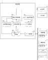
- FIG. 2 shows a schematic block diagram of the functions provided by the diagnostic apparatus 1 according to the first embodiment of the present invention.
- Each function included in the diagnostic apparatus 1 according to the present embodiment is realized by the CPU 11 included in the diagnostic apparatus 1 shown in FIG. 1 executing a system program and controlling the operation of each part of the diagnostic apparatus 1.
- the diagnostic device 1 of the present embodiment includes a data acquisition unit 100, a state determination unit 110, a parts replacement detection unit 120, and a model adaptation implementation unit 130. Further, the RAM 13 to the non-volatile memory 14 of the diagnostic device 1 include an acquisition data storage unit 200 that stores data acquired from the control device 3 that controls the industrial machine, and a model storage unit 210 that stores a model used for diagnosis in advance. A determination history storage unit 220 for storing the history of the state determination result of the industrial machine by the state determination unit 110 is prepared in advance.
- the data acquisition unit 100 executes a system program read from the ROM 12 by the CPU 11 included in the diagnostic apparatus 1 shown in FIG. 1, mainly performs arithmetic processing using the RAM 13 and the non-volatile memory 14 by the CPU 11, and uses the interface 20. It is realized by performing communication processing.
- the data acquisition unit 100 acquires data indicating the operating state of the industrial machine from the control device 3 that controls the industrial machine.
- the data acquired by the data acquisition unit 100 may be machine setting information such as various offset values and time constants set in the industrial machine or the control device.
- the data acquired by the data acquisition unit 100 includes information indicating the start / stop of the industrial machine, the position, speed, and acceleration of the drive unit of the industrial machine, the current / voltage value of the drive unit of the industrial machine, the load of the drive unit, and the load of each unit. Machine operation information such as temperature, sound around the industrial machine, and an image of the operating range of the industrial machine may be used.
- the data acquired by the data acquisition unit 100 may be data that can be directly acquired from the industrial machine, or may be data detected by the industrial machine or a sensor 4 attached to the periphery of the industrial machine.
- the data acquired by the data acquisition unit 100 may be data acquired at a predetermined time or time series data acquired at a predetermined cycle.
- the data acquired by the data acquisition unit 100 is stored in the acquisition data storage unit 200 in association with the detected time, the identifier of the industrial machine, and the like.
- the state determination unit 110 is realized by executing a system program read from the ROM 12 by the CPU 11 included in the diagnostic device 1 shown in FIG. 1 and performing arithmetic processing mainly by the CPU 11 using the RAM 13 and the non-volatile memory 14. NS.
- the state determination unit 110 executes a state determination process of the industrial machine using the diagnostic model stored in the model storage unit 210 based on the data acquired by the data acquisition unit 100.
- the model storage unit 210 stores a diagnostic model previously constructed based on the data of the industrial machine.
- the diagnostic model may be a model constructed by so-called unsupervised learning, for example, a cluster of data sets acquired when an industrial machine is operating normally.
- the state determination unit 110 determines the industrial machine based on how far the vector value of the machine operation information acquired from the industrial machine is from the cluster center of the data set acquired during normal operation (distance). It is possible to diagnose whether the state of is within the normal range or whether it is operating abnormally.
- the diagnostic model may be a model constructed by so-called supervised learning, for example, a neural network for diagnosing normality / abnormality of an industrial machine or a regression equation.
- the state determination unit 110 inputs the machine operation information acquired from the industrial machine into the model, and based on the output value (score value), is the state of the industrial machine within the normal range? It is possible to diagnose whether it is operating abnormally.
- the determination result by the state determination unit 110 is output to the display device 70.
- the display device 70 may display the fact and warn the operator with light, sound, or the like. Further, if necessary, a command to stop the operation of the industrial machine may be output to the industrial machine (control device 3 for controlling) determined to be in an abnormal state.
- the determination result of the state of the industrial machine by the state determination unit 110 is further output to the parts replacement detection unit 120 and stored as the determination history information in the determination history storage unit 220.
- the state determination unit 110 also stores a predetermined calculated value used for determining the state of the industrial machine (in the above example, a distance from the cluster center used for diagnosis, a score value, etc.) as determination history information. You may.
- the component replacement detection unit 120 is realized by executing a system program read from the ROM 12 by the CPU 11 included in the diagnostic device 1 shown in FIG. 1 and performing arithmetic processing mainly by the CPU 11 using the RAM 13 and the non-volatile memory 14. Will be done.
- the parts replacement detection unit 120 of the parts of the industrial machine is based on the machine setting information and the machine operation information acquired from the control device 3 that controls the industrial machine, and the state determination history information of the industrial machine by the state determination unit 110. Detect that a replacement has taken place. For example, when the tool offset value is changed in the negative direction from the machine setting information to a predetermined threshold value or more, the component replacement detection unit 120 may detect that the tool has been replaced.
- the part replacement detection unit 120 detects that a tool for some part has been used, for example, when the operation is stopped after an alarm is generated in the industrial machine and the machine is restarted after a predetermined time has elapsed. good.
- the determination result of the state of the industrial machine by the state determination unit 110 improves in a normal direction to a predetermined threshold value or more as compared with the determination history information stored in the determination history storage unit 220. If this happens, it may be detected that a tool of some part has been used.
- the parts replacement detection unit 120 detects the replacement of parts in the industrial machine by using at least one of the machine setting information, the machine operation information, and the determination result by the state determination unit 110 according to the characteristics of the industrial machine. You may try to do it. For example, replacement of parts may be detected from a predetermined time-series change in at least one of machine setting information, machine operation information, and determination history information, or a combination thereof.
- the parts replacement detection unit 120 may display the fact on the display device 70. Further, when the parts replacement detection unit 120 detects the parts replacement of the industrial machine, the parts replacement detection unit 120 may output to that effect to the model adaptation execution unit 130.
- the model adaptation execution unit 130 is realized by executing a system program read from the ROM 12 by the CPU 11 included in the diagnostic device 1 shown in FIG. 1 and performing arithmetic processing mainly by the CPU 11 using the RAM 13 and the non-volatile memory 14. Will be done.
- the model adaptation execution unit 130 detects the replacement of parts of the industrial machine, the model adaptation execution unit 130 executes a process of adapting the model stored in the model storage unit 210 to the diagnosis of the state of the industrial machine after the parts replacement.
- the model adaptation executing unit 130 may adapt the diagnostic model to the industrial machine after the parts replacement, for example, by performing a re-learning process using the data acquired from the industrial machine after the parts replacement.
- the model adaptation executing unit 130 may adapt the diagnostic model to the industrial machine after the parts replacement, for example, by performing additional learning processing using the data acquired from the industrial machine after the parts replacement.
- the model adaptation execution unit 130 expresses the parameters of the model for diagnosis (for example, the center position of the cluster, the spread of the cluster, and the model in an equation so as to adapt to the data acquired from the industrial machine after parts replacement, for example. If this is the case, the coefficient may be adjusted, and if it is represented by a neural network, the weighting coefficient, etc.) may be adjusted to adapt the diagnostic model to the industrial machine after parts replacement.
- the model adaptation implementation unit 130 switches the model used for diagnosis to another diagnostic model that adapts to the data acquired from the industrial machine after the parts replacement, so that the industrial machine after the parts replacement can be used for diagnosis.
- the model may be adapted.
- the diagnostic device 1 acquires a model used for diagnosing the state of the industrial machine from the industrial machine after the parts are replaced when it detects that the parts have been replaced in the industrial machine.
- the process of adapting to the data is automatically performed. Therefore, the operator does not have to judge the execution of the model adaptation process by himself / herself, and the burden on the operator can be reduced.
- whether or not the component replacement detection unit 120 performs model adaptation processing on the display device 70 when it detects that a component of an industrial machine has been replaced It may be displayed to confirm.
- the parts replacement detection unit 120 detects that a part of an industrial machine has been replaced for example, "Did you replace the part A with YYYY / MM / DD HH: MM? If it is replaced, the model adaptation process. (Yes / No), etc. is displayed, and when the operator selects Yes, the model adaptation implementation unit 130 executes the model adaptation process. Since the detection of component replacement by the component replacement detection unit 120 may not be accurate, it is possible to prevent unnecessary model adaptation processing by leaving the final judgment to the user.
Landscapes
- Engineering & Computer Science (AREA)
- Physics & Mathematics (AREA)
- General Physics & Mathematics (AREA)
- Automation & Control Theory (AREA)
- Business, Economics & Management (AREA)
- Manufacturing & Machinery (AREA)
- Human Computer Interaction (AREA)
- Human Resources & Organizations (AREA)
- Chemical Kinetics & Catalysis (AREA)
- Chemical & Material Sciences (AREA)
- Marketing (AREA)
- General Business, Economics & Management (AREA)
- Tourism & Hospitality (AREA)
- Theoretical Computer Science (AREA)
- Strategic Management (AREA)
- Robotics (AREA)
- Mechanical Engineering (AREA)
- Quality & Reliability (AREA)
- Operations Research (AREA)
- Entrepreneurship & Innovation (AREA)
- Economics (AREA)
- Testing And Monitoring For Control Systems (AREA)
- Numerical Control (AREA)
Priority Applications (4)
| Application Number | Priority Date | Filing Date | Title |
|---|---|---|---|
| CN202180012892.5A CN115053195A (zh) | 2020-02-07 | 2021-02-05 | 诊断装置 |
| US17/760,098 US20230038415A1 (en) | 2020-02-07 | 2021-02-05 | Diagnosis device |
| DE112021000920.6T DE112021000920T5 (de) | 2020-02-07 | 2021-02-05 | Diagnosevorrichtung |
| JP2021575871A JP7425094B2 (ja) | 2020-02-07 | 2021-02-05 | 診断装置 |
Applications Claiming Priority (2)
| Application Number | Priority Date | Filing Date | Title |
|---|---|---|---|
| JP2020020064 | 2020-02-07 | ||
| JP2020-020064 | 2020-02-07 |
Publications (1)
| Publication Number | Publication Date |
|---|---|
| WO2021157676A1 true WO2021157676A1 (ja) | 2021-08-12 |
Family
ID=77199940
Family Applications (1)
| Application Number | Title | Priority Date | Filing Date |
|---|---|---|---|
| PCT/JP2021/004199 Ceased WO2021157676A1 (ja) | 2020-02-07 | 2021-02-05 | 診断装置 |
Country Status (5)
| Country | Link |
|---|---|
| US (1) | US20230038415A1 (https=) |
| JP (1) | JP7425094B2 (https=) |
| CN (1) | CN115053195A (https=) |
| DE (1) | DE112021000920T5 (https=) |
| WO (1) | WO2021157676A1 (https=) |
Cited By (4)
| Publication number | Priority date | Publication date | Assignee | Title |
|---|---|---|---|---|
| JP2022175959A (ja) * | 2021-05-14 | 2022-11-25 | 株式会社日立製作所 | 機械学習システム及び機械学習システムによる機械学習モデル管理方法 |
| WO2023099059A1 (de) * | 2021-11-30 | 2023-06-08 | Fraunhofer-Gesellschaft zur Förderung der angewandten Forschung e.V. | Verfahren zum überwachen eines produktionsprozesses in echtzeit mittels einer maschinen-lern-komponente |
| WO2023153193A1 (ja) * | 2022-02-09 | 2023-08-17 | 三菱電機株式会社 | 設備診断システム、学習装置、学習済みモデル、および学習済みモデルの生成方法 |
| WO2024116232A1 (ja) * | 2022-11-28 | 2024-06-06 | ファナック株式会社 | 設定装置及び制御条件の決定方法 |
Families Citing this family (1)
| Publication number | Priority date | Publication date | Assignee | Title |
|---|---|---|---|---|
| US12585254B2 (en) * | 2020-11-02 | 2026-03-24 | Hitachi, Ltd. | Industrial system, abnormality detection system, and abnormality detection method |
Citations (4)
| Publication number | Priority date | Publication date | Assignee | Title |
|---|---|---|---|---|
| EP2028609A2 (en) * | 2007-04-24 | 2009-02-25 | Honeywell International Inc. | Methods for optimizing diagnostic reasoner models |
| JP2009217708A (ja) * | 2008-03-12 | 2009-09-24 | Omron Corp | リモート装置及びi/o機器の交換時期管理システム |
| WO2017179189A1 (ja) * | 2016-04-15 | 2017-10-19 | 三菱電機株式会社 | プラント監視制御システム |
| JP2019185415A (ja) * | 2018-04-11 | 2019-10-24 | 日産自動車株式会社 | 異常判定装置及び異常判定方法 |
Family Cites Families (28)
| Publication number | Priority date | Publication date | Assignee | Title |
|---|---|---|---|---|
| JPH11188572A (ja) * | 1997-12-24 | 1999-07-13 | Minoru Okada | Nc工作機械の工具交換時における刃先位置設定方法及び、この方法を実行するnc工作機械 |
| US7254749B2 (en) * | 2002-10-16 | 2007-08-07 | Sun Microsystems, Inc. | System and method for storage of operational parameters on components |
| US6840445B2 (en) * | 2002-12-09 | 2005-01-11 | Caterpillar Inc. | System and method for compiling a machine service history |
| JP4580846B2 (ja) * | 2005-08-26 | 2010-11-17 | ヤマザキマザック株式会社 | Nc工作機械 |
| GB0709420D0 (en) * | 2007-05-17 | 2007-06-27 | Rolls Royce Plc | Machining process monitor |
| JP4453764B2 (ja) * | 2008-02-22 | 2010-04-21 | トヨタ自動車株式会社 | 車両診断装置、車両診断システム、診断方法 |
| JP4730433B2 (ja) * | 2008-12-24 | 2011-07-20 | 富士ゼロックス株式会社 | 故障診断システム、情報更新装置およびプログラム |
| JP5746128B2 (ja) * | 2012-12-04 | 2015-07-08 | ファナック株式会社 | 保守部品の交換時期判断機能を有する工作機械 |
| WO2016157278A1 (ja) * | 2015-03-27 | 2016-10-06 | 株式会社日立製作所 | 故障予兆診断システム、及びその方法 |
| US10410135B2 (en) * | 2015-05-21 | 2019-09-10 | Software Ag Usa, Inc. | Systems and/or methods for dynamic anomaly detection in machine sensor data |
| DE102016008987B4 (de) * | 2015-07-31 | 2021-09-16 | Fanuc Corporation | Maschinenlernverfahren und Maschinenlernvorrichtung zum Lernen von Fehlerbedingungen, und Fehlervorhersagevorrichtung und Fehlervorhersagesystem, das die Maschinenlernvorrichtung einschließt |
| JP6148316B2 (ja) * | 2015-07-31 | 2017-06-14 | ファナック株式会社 | 故障条件を学習する機械学習方法及び機械学習装置、並びに該機械学習装置を備えた故障予知装置及び故障予知システム |
| JP5845374B1 (ja) * | 2015-08-05 | 2016-01-20 | 株式会社日立パワーソリューションズ | 異常予兆診断システム及び異常予兆診断方法 |
| JP5946572B1 (ja) * | 2015-08-05 | 2016-07-06 | 株式会社日立パワーソリューションズ | 異常予兆診断システム及び異常予兆診断方法 |
| JP6572062B2 (ja) * | 2015-08-26 | 2019-09-04 | 日立建機株式会社 | 診断装置 |
| JP6526583B2 (ja) * | 2016-02-10 | 2019-06-05 | アイシン・エィ・ダブリュ株式会社 | 切削機械監視装置 |
| JP6939053B2 (ja) * | 2016-07-15 | 2021-09-22 | 株式会社リコー | 診断装置、プログラムおよび診断システム |
| US10739764B2 (en) * | 2016-07-15 | 2020-08-11 | Ricoh Company, Ltd. | Diagnostic apparatus, diagnostic system, diagnostic method, and recording medium |
| JP6805600B2 (ja) * | 2016-07-21 | 2020-12-23 | 株式会社リコー | 診断装置、診断システム、診断方法およびプログラム |
| US10352299B2 (en) * | 2016-08-05 | 2019-07-16 | General Electric Company | System and method for automatically updating wind turbine data based on component self-identification |
| JP6705903B2 (ja) * | 2016-09-02 | 2020-06-03 | 株式会社日立製作所 | 診断装置、診断方法及び診断プログラム |
| WO2018092957A1 (ko) * | 2016-11-21 | 2018-05-24 | 주식회사 알고리고 | 신경망 모델에서 입력값에 대한 재학습 여부 결정 방법, 장치 및 프로그램 |
| JP6386520B2 (ja) * | 2016-12-13 | 2018-09-05 | ファナック株式会社 | 数値制御装置及び機械学習装置 |
| JP6450738B2 (ja) * | 2016-12-14 | 2019-01-09 | ファナック株式会社 | 工作機械における工具のビビり発生の予兆を検知する機械学習装置、cnc装置および機械学習方法 |
| JP6837848B2 (ja) * | 2017-01-27 | 2021-03-03 | オークマ株式会社 | 診断装置 |
| JP6956028B2 (ja) * | 2018-02-22 | 2021-10-27 | ファナック株式会社 | 故障診断装置及び機械学習装置 |
| JP2019185422A (ja) * | 2018-04-11 | 2019-10-24 | 株式会社Ye Digital | 故障予知方法、故障予知装置および故障予知プログラム |
| US10810513B2 (en) * | 2018-10-25 | 2020-10-20 | The Boeing Company | Iterative clustering for machine learning model building |
-
2021
- 2021-02-05 JP JP2021575871A patent/JP7425094B2/ja active Active
- 2021-02-05 CN CN202180012892.5A patent/CN115053195A/zh active Pending
- 2021-02-05 WO PCT/JP2021/004199 patent/WO2021157676A1/ja not_active Ceased
- 2021-02-05 US US17/760,098 patent/US20230038415A1/en not_active Abandoned
- 2021-02-05 DE DE112021000920.6T patent/DE112021000920T5/de active Pending
Patent Citations (4)
| Publication number | Priority date | Publication date | Assignee | Title |
|---|---|---|---|---|
| EP2028609A2 (en) * | 2007-04-24 | 2009-02-25 | Honeywell International Inc. | Methods for optimizing diagnostic reasoner models |
| JP2009217708A (ja) * | 2008-03-12 | 2009-09-24 | Omron Corp | リモート装置及びi/o機器の交換時期管理システム |
| WO2017179189A1 (ja) * | 2016-04-15 | 2017-10-19 | 三菱電機株式会社 | プラント監視制御システム |
| JP2019185415A (ja) * | 2018-04-11 | 2019-10-24 | 日産自動車株式会社 | 異常判定装置及び異常判定方法 |
Cited By (5)
| Publication number | Priority date | Publication date | Assignee | Title |
|---|---|---|---|---|
| JP2022175959A (ja) * | 2021-05-14 | 2022-11-25 | 株式会社日立製作所 | 機械学習システム及び機械学習システムによる機械学習モデル管理方法 |
| JP7587472B2 (ja) | 2021-05-14 | 2024-11-20 | 株式会社日立製作所 | 機械学習システム及び機械学習システムによる機械学習モデル管理方法 |
| WO2023099059A1 (de) * | 2021-11-30 | 2023-06-08 | Fraunhofer-Gesellschaft zur Förderung der angewandten Forschung e.V. | Verfahren zum überwachen eines produktionsprozesses in echtzeit mittels einer maschinen-lern-komponente |
| WO2023153193A1 (ja) * | 2022-02-09 | 2023-08-17 | 三菱電機株式会社 | 設備診断システム、学習装置、学習済みモデル、および学習済みモデルの生成方法 |
| WO2024116232A1 (ja) * | 2022-11-28 | 2024-06-06 | ファナック株式会社 | 設定装置及び制御条件の決定方法 |
Also Published As
| Publication number | Publication date |
|---|---|
| CN115053195A (zh) | 2022-09-13 |
| DE112021000920T5 (de) | 2022-11-24 |
| JPWO2021157676A1 (https=) | 2021-08-12 |
| US20230038415A1 (en) | 2023-02-09 |
| JP7425094B2 (ja) | 2024-01-30 |
Similar Documents
| Publication | Publication Date | Title |
|---|---|---|
| JP7425094B2 (ja) | 診断装置 | |
| JP6711854B2 (ja) | 故障予測装置及び機械学習装置 | |
| US10996650B2 (en) | Numerical control system | |
| JP6810097B2 (ja) | 異常検出器 | |
| JP6693919B2 (ja) | 制御装置及び機械学習装置 | |
| JP7381280B2 (ja) | 診断装置及び機械学習装置 | |
| JP6568167B2 (ja) | 異常検知装置及び機械学習装置 | |
| CN209297151U (zh) | 异常因素确定装置 | |
| JP7148311B2 (ja) | 製品検査装置 | |
| JP2019012392A (ja) | 制御装置及び機械学習装置 | |
| US10962953B2 (en) | Adjustment of a deviation of an axis position of driving unit of machine tool | |
| CN112599234A (zh) | 诊断装置 | |
| CN111788042A (zh) | 机器人的预见性分析 | |
| CN112084834A (zh) | 诊断装置 | |
| JP2021076395A (ja) | 診断装置 | |
| JP2019150932A (ja) | 衝突位置推定装置及び機械学習装置 | |
| US12032354B2 (en) | Program restart assisting apparatus | |
| CN115666836A (zh) | 工具诊断装置 | |
| CN117795308A (zh) | 控制装置以及控制方法 | |
| JP7695368B2 (ja) | 診断装置、及びプログラムを記録した記録媒体 | |
| WO2022138775A1 (ja) | 異常分類装置 | |
| JP7853331B2 (ja) | 診断装置及びコンピュータ読み取り可能な記録媒体 | |
| CN121753043A (zh) | 异常检测装置以及计算机可读取的记录介质 | |
| WO2024176390A1 (ja) | データ分割装置、及びコンピュータ読み取り可能な記録媒体 |
Legal Events
| Date | Code | Title | Description |
|---|---|---|---|
| 121 | Ep: the epo has been informed by wipo that ep was designated in this application |
Ref document number: 21750071 Country of ref document: EP Kind code of ref document: A1 |
|
| ENP | Entry into the national phase |
Ref document number: 2021575871 Country of ref document: JP Kind code of ref document: A |
|
| 122 | Ep: pct application non-entry in european phase |
Ref document number: 21750071 Country of ref document: EP Kind code of ref document: A1 |