WO2021156910A1 - 可変容量素子 - Google Patents
可変容量素子 Download PDFInfo
- Publication number
- WO2021156910A1 WO2021156910A1 PCT/JP2020/003910 JP2020003910W WO2021156910A1 WO 2021156910 A1 WO2021156910 A1 WO 2021156910A1 JP 2020003910 W JP2020003910 W JP 2020003910W WO 2021156910 A1 WO2021156910 A1 WO 2021156910A1
- Authority
- WO
- WIPO (PCT)
- Prior art keywords
- electrode
- container
- gas
- capacitance element
- plasma
- Prior art date
- Legal status (The legal status is an assumption and is not a legal conclusion. Google has not performed a legal analysis and makes no representation as to the accuracy of the status listed.)
- Ceased
Links
Images



Classifications
-
- H—ELECTRICITY
- H01—ELECTRIC ELEMENTS
- H01G—CAPACITORS; CAPACITORS, RECTIFIERS, DETECTORS, SWITCHING DEVICES, LIGHT-SENSITIVE OR TEMPERATURE-SENSITIVE DEVICES OF THE ELECTROLYTIC TYPE
- H01G7/00—Capacitors in which the capacitance is varied by non-mechanical means; Processes of their manufacture
- H01G7/06—Capacitors in which the capacitance is varied by non-mechanical means; Processes of their manufacture having a dielectric selected for the variation of its permittivity with applied voltage, i.e. ferroelectric capacitors
-
- H—ELECTRICITY
- H05—ELECTRIC TECHNIQUES NOT OTHERWISE PROVIDED FOR
- H05H—PLASMA TECHNIQUE; PRODUCTION OF ACCELERATED ELECTRICALLY-CHARGED PARTICLES OR OF NEUTRONS; PRODUCTION OR ACCELERATION OF NEUTRAL MOLECULAR OR ATOMIC BEAMS
- H05H1/00—Generating plasma; Handling plasma
- H05H1/24—Generating plasma
Definitions
- the present disclosure relates to a variable capacitance element in which the dielectric medium is plasma.
- Patent Document 1 describes a circuit element that makes the capacitance value variable by adjusting the relative permittivity of plasma formed between parallel plate electrodes.
- the conventional variable capacitance element in which the dielectric medium is plasma has a problem that a large amount of electric power is required to adjust the relative permittivity of plasma.
- the present disclosure solves the above-mentioned problems, and provides a variable capacitance element capable of controlling the capacitance value with a smaller power than a variable capacitance element in which the plasma formed between the parallel plate electrodes is a dielectric medium.
- the purpose is to get.
- the variable capacitance element has a hollow cylindrical shape, and has a container in which gas is sealed in a space provided between an outer peripheral surface and an inner peripheral surface of the hollow cylindrical shape, and an outer peripheral surface of the hollow cylindrical shape.
- the first electrode provided in the space, the second electrode provided on the inner peripheral surface of the hollow cylindrical shape and facing the first electrode via the space portion, and the gas sealed in the space portion are plasma. It is provided with a power adjusting unit that makes the capacitance value between the first electrode and the second electrode variable by adjusting the power to be in a state.
- variable capacitance element in a container having a hollow cylindrical shape, gas is sealed in a space provided between an outer peripheral surface and an inner peripheral surface of the hollow cylindrical shape.
- FIG. 2A is a block diagram showing the configuration of the variable capacitance element according to the first embodiment
- FIG. 2B is a cross-sectional view showing a cross section of the container in FIG. 2A cut by a plane orthogonal to the central axis.
- FIG. 4A is a perspective view showing a container included in a conventional variable capacitance element
- FIG. 4B is a cross-sectional view showing a cross section of the container in FIG. 4A cut along a plane along the width direction.
- FIG. 1 It is a characteristic figure which shows the control parameter dependence of the capacitance value in a variable capacitance element. It is a block diagram which shows the structure of the variable capacitance element which concerns on Embodiment 2. FIG. It is a block diagram which shows the structure of the variable capacitance element which concerns on Embodiment 3.
- FIG. 1 is a characteristic diagram showing the electron density ne dependence of the relative permittivity ⁇ p of the plasma formed between the electrodes.
- the relative permittivity ⁇ p of plasma between electrodes that are spatially uniform and in the absence of a magnetic field can be expressed by the following equation (1).
- the omega p is the angular frequency of the plasma
- v m is the electron collision frequency in the plasma
- omega is the angular frequency of the electromagnetic wave.
- the angular frequency omega p of the plasma by using the electron density n e, mass m e and the dielectric constant epsilon 0 of vacuum of the electron plasma can be represented by the following formula (2).
- the collision frequency v m of the electrons in the plasma it is considered that the elastic collisions between electrons and neutral particles is dominant, can be represented by the following formula (3).
- n n is the density of neutral particles between the electrodes
- ⁇ e ⁇ n is the elastic collision frequency between the electron and the neutral particle with the electron temperature as an argument.
- k B is the Boltzmann constant
- Te is the electron temperature.
- the relative permittivity ⁇ p of the plasma is shown in the following equation (4) because the values other than n n , ne and Te are constants. It can be represented by a function with n n , ne and Te as control parameters.
- the electromagnetic wave (the frequency of the electromagnetic wave 30 (MHz)) the angular frequency ⁇ is 188 (Mrad / s) of a collision frequency v m is 2.48 (MHz)
- the gas to a plasma state type is argon
- the gas temperature is 1 (eV)
- the gas pressure is 0.1 (Pa)
- the solid line shows the electron density ne dependence of the real part Re ( ⁇ p ) of the relative permittivity ⁇ p of the plasma.
- the alternate long and short dash line indicates the electron density ne dependence of the imaginary portion Im ( ⁇ p ) of the relative permittivity ⁇ p of the plasma.
- the electron density n real part Re in accordance with a change in e ( ⁇ p) and the imaginary part Im ( ⁇ p) is changed.
- the relative dielectric constant of the plasma epsilon p is variable by controlling the electron density n e.
- the capacitance value C of a capacitor configured by sandwiching a dielectric medium having a relative permittivity ⁇ r so as to have a distance d between the electrodes using two electrodes which are conductor plates having an area S is as follows. It can be expressed by the equation (5).
- the capacitance value C is variable.
- FIG. 2A is a block diagram showing the configuration of the variable capacitance element 1 according to the first embodiment.
- the variable capacitance element 1 includes a container 2, a first electrode 3a, a second electrode 3b, a third electrode 4a, a fourth electrode 4b, a first lead wire 5a, and a second lead wire. It includes 5b and a variable power supply device 6.
- the container 2 is a container having a hollow cylindrical shape and is made of a non-metal material. For the container 2, a dielectric material having a low dielectric loss such as glass is desirable.
- FIG. 2B is a cross-sectional view showing a cross section of the container 2 cut by a plane orthogonal to the central axis A.
- the inner cylindrical portion 2b is arranged on the inner peripheral side of the outer cylindrical portion 2a, and the outer peripheral surface of the outer cylindrical portion 2a and the inner peripheral surface of the inner cylindrical portion 2b are arranged.
- a space portion 2e is formed between them.
- a first end surface 2c is provided at one end of the space portion 2e along the longitudinal direction, and the end portion of the space portion 2e opposite to the first end surface 2c. Is provided with a second end face 2d.
- the space portion 2e is isolated from the outside by the first end face 2c and the second end face 2d.
- Gas is sealed in the space 2e.
- the gas sealed in the space 2e is a gas that is easily ionized, and includes, for example, helium, neon, and argon.
- a first electrode 3a is provided on the outer peripheral surface of the outer cylindrical portion 2a
- a second electrode 3b is provided on the inner peripheral surface of the inner cylindrical portion 2b.
- a third electrode 4a is provided on the first end surface 2c inside the space portion 2e
- a fourth electrode 4b is provided on the second end surface 2d inside the space portion 2e.
- Through holes for power supply are formed on the first end face 2c and the second end face 2d.
- the end portion of the first conductor 5a is connected to the third electrode 4a through the through hole portion in the first end surface 2c.
- the end portion of the second conductor 5b is connected to the fourth electrode 4b through the through hole portion in the second end surface 2d.
- the through hole in the first end surface 2c is closed by the end of the first conductor 5a connected to the third electrode 4a, and the through hole in the second end surface 2d is the fourth electrode 4b. It is blocked by the end of the second conductor 5b connected to. As a result, the gas sealed in the space 2e does not leak to the outside. Since the first electrode 3a is arranged on the outer peripheral surface of the outer cylindrical portion 2a and the second electrode 3b is arranged on the inner peripheral surface of the inner cylindrical portion 2b, the first electrode 3a and the second electrode 3a and the second electrode 3a are arranged. The electrodes 3b of the above are not in contact with the gas enclosed in the space 2e.
- the variable power supply device 6 makes the capacitance value C between the first electrode 3a and the second electrode 3b variable by adjusting the electric power that puts the gas enclosed in the space 2e into a plasma state. It is a power adjustment unit. For example, the variable power supply device 6 supplies high-voltage power to the third electrode 4a and the fourth electrode 4b through the first conductor 5a and the second conductor 5b, so that the gas enclosed in the space 2e Is ionized to a plasma state.
- the variable power supply device 6 adjusts the electric power supplied to the gas in the space 2e through the third electrode 4a and the fourth electrode 4b when the gas enclosed in the space 2e is in a plasma state. It changes the electron density n e of the plasma. As shown in the above formula (4), the dielectric constant epsilon p of the plasma varies depending on the plasma electron density n e. Therefore, the variable capacitance element 1 can change the capacitance value C between the first electrode 3a and the second electrode 3b by adjusting the electric power supplied to the gas in the space 2e. Is.
- FIG. 3 is an equivalent circuit diagram showing an equivalent circuit of the variable capacitance element 1.
- the equivalent circuit of the variable capacitance element 1 is a circuit in which the capacitor 7 and the capacitor 8 are connected in series.
- the capacitor 7 is a concentric cylindrical capacitor composed of an outer cylindrical portion 2a and an inner cylindrical portion 2b, and the material of the container 2 is a dielectric medium.
- the capacitor 8 is a cylindrical capacitor in which the plasma inside the space 2e is a dielectric medium.
- the capacitance value C w of the capacitor 7 can be expressed by the following equation (6) using the specific complex dielectric constant ⁇ w of the material of the container 2.
- the electrode length l is the length of the first electrode 3a and the second electrode 3b along the longitudinal direction of the container 2, as shown in FIG. 2A.
- the radius r of the hollow portion is the distance from the central axis A to the inner peripheral surface of the inner cylindrical portion 2b.
- the thickness t of the wall material of the container 2 is, for example, the thickness of the wall material of the inner cylindrical portion 2b.
- the distance d between the electrodes is the distance between the first electrode 3a and the second electrode 3b as shown in FIG. 2B.
- the capacitance value C p of the capacitor 8 is calculated from the following equation (7) using the relative permittivity ⁇ p of the plasma given by the above equation (4).
- the capacitance value C new of the variable capacitance element 1 can be calculated according to the following equation (8) by using the above equations (6) and (7).
- the relative dielectric constant epsilon p of the plasma as shown in the equation (4), so is represented by a function of the electron density n e of the plasma parameters, the capacitance value C new, the plasma electron density n e It becomes variable by controlling.
- FIG. 4A is a perspective view showing a container 100 included in a conventional variable capacitance element.
- the container 100 is a rectangular parallelepiped container.
- the electrode 100a and the electrode 100b are plate electrodes constituting a parallel plate electrode, and the electrode 100a is provided on one of the main surfaces (widest surfaces) facing each other in the rectangular parallelepiped container 100, and the electrode 100b is provided on the other side. ing.
- An electrode 101a is provided on one of the inner wall surfaces of the container 100, and an electrode 101b is provided on the inner wall surface facing the electrode 101a inside the container 100. Further, the container 100 is filled with a gas that is easily ionized.
- the conventional variable capacitance element provided with the container 100 puts the gas sealed in the container 100 into a plasma state by applying a high voltage to the electrodes 101a and 101b, and adjusts the electric power supplied to the electrodes 101a and 101b. As a result, the capacitance value Cold between the electrode 100a and the electrode 100b is changed.
- FIG. 4B is a cross-sectional view showing a cross section of the container 100 in FIG. 4A cut along a plane along the width direction.
- the distance between the electrode 100a and the electrode 100b is d
- the thickness of the wall material of the container 100 is t.
- the electrode lengths of the electrodes 100a and 100b are l
- the electrode width is w.
- the capacitance value Cold in the conventional variable capacitance element can be expressed by using the following equation (9).
- FIG. 5 is a characteristic diagram showing the control parameter dependence of the capacitance value C in the variable capacitance element.
- Control parameter is the plasma electron density n e
- the variable capacitance element includes a variable capacitance element 1 according to the first embodiment
- is a conventional variable capacitance element comprises a container 100 shown in FIGS. 4A and 4B .
- the solid line shows the electron density n e dependence of the capacitance value C new new
- dashed line shows the electron density n e dependence of the capacitance value C old.
- the electron density n e dependence of the electron density n e dependence and electrostatic capacitance value C old capacitance value C new is the formula (1), the formula (5) and the formula (9) It was calculated using. Further, in order to compare both of the variable capacitance element under the same conditions, the capacitance value C new and C old electrode length l used to calculate the, wall material thickness t, the material of the electrode distance d and containers, Both variable capacitance elements are used together. Further, in order to match the control width of the capacitance value with both variable capacitance elements, the electrode width w in the above equation (9) is calculated using the following equation (10).
- the angular frequency of the electromagnetic wave omega has the material of the container complex dielectric constant epsilon w, electron collision frequency v m in the plasma, the electrode length l, radius of the hollow portion r and the distance d between the electrodes are set as follows.
- the angular frequency ⁇ of the electromagnetic wave is 188 (Mrad / s) (the frequency of the electromagnetic wave is 30 (MHz)).
- quartz glass having a specific complex dielectric constant ⁇ w of 3.8 is assumed.
- the gas to be sealed in the container assuming argon, the gas temperature and 1 (eV), by the gas pressure and 0.1 (Pa), the collision frequency v m of the electrons in the plasma 2.48 (MHz). Further, the electrode length l is 40 (mm), the radius r of the hollow portion is 2 (mm), and the distance d between the electrodes is 8 (mm).
- both the capacitance values C new and Cold have a divergent region.
- both of the variable capacitance elements are equal capacitance value of the control range (C new> 6.81 (pF) , C old> 6.81 (pF) )have.
- the capacitance value C new diverges on the side where the electron density ne is lower than that of the capacitance value Cold.
- the capacitance value C new diverges in the electron density n e is 1.18 ⁇ 10 14 (m -3) , the capacitance value C old, the electron density n e is 6.13 ⁇ 10 14 ( It diverges at m -3). That is, the variable capacitance element 1 can control the capacitance value with the same control width even if the electron density is about 52% as compared with the conventional variable capacitance element.
- variable capacitance element 1 Since the electron density of the plasma and the discharge power supplied between the electrodes have a proportional correlation, the variable capacitance element 1 has a capacitance value having the same control width with a small amount of power as compared with the conventional variable capacitance element. It is possible to realize the control of.
- the discharge electrodes (third electrode 4a and fourth electrode 4b) provided inside the container 2 are worn by plasma sputtering.
- the intensity of this sputtering is proportional to the discharge power for forming the plasma. Therefore, in the variable capacitance element 1 capable of suppressing the discharge power to a small power, the wear of the discharge electrode is reduced, and the life can be extended as compared with the conventional variable capacitance element.
- the gas is provided in the space 2e provided between the outer peripheral surface and the inner peripheral surface of the hollow cylindrical shape in the container 2 having the hollow cylindrical shape. Is enclosed.
- the first electrode 3a provided on the outer peripheral surface of the hollow cylinder and the second electrode 3b provided on the inner peripheral surface of the hollow cylinder
- the capacitance value C new between them becomes variable.
- the variable capacitance element 1 can control the capacitance value C new with less power than the conventional variable capacitance element in which the plasma formed between the electrodes 100a and 100b is a dielectric medium. ..
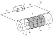
- FIG. 6 is a block diagram showing a configuration of the variable capacitance element 1A according to the second embodiment.
- the variable capacitance element 1A includes a container 2A, a first electrode 3a, a second electrode 3b, a coil 9, a first conductor 5a, a second conductor 5b, and a variable power supply device 6.
- the container 2A is a container having a hollow cylindrical shape composed of an outer cylindrical portion 2a and an inner cylindrical portion 2b, and is made of a non-metallic material.
- a dielectric material having a low dielectric loss such as glass is desirable.
- the container 2A is provided with the space portion 2e shown in FIG. 2B between the outer peripheral surface of the outer cylindrical portion 2a and the inner peripheral surface of the inner cylindrical portion 2b. Further, the first electrode 3a is arranged on the outer peripheral surface of the outer cylindrical portion 2a, and the second electrode 3b is arranged on the inner peripheral surface of the inner cylindrical portion 2b. However, the container 2A does not have the third electrode 4a and the fourth electrode 4b shown in FIG. 2A, and a coil 9 is provided instead. Gases such as helium, neon, and argon are sealed in the space 2e.
- the coil 9 is a conductor portion spirally wound around the outer peripheral surface of the container 2A (the outer peripheral surface of the outer cylindrical portion 2a) so as to be electrically insulated from the first electrode 3a and the second electrode 3b. ..
- One end of the coil 9 is connected to the end of the first conductor 5a, and the other end of the coil 9 is connected to the end of the second conductor 5b.
- the variable power supply device 6 supplies high-frequency power to the coil 9 through the first conductor 5a and the second conductor 5b to put the gas enclosed in the space 2e into a plasma state.
- Variable power supply 6 when gas enclosed in the space 2e is a plasma state, by adjusting the power supplied to the coil 9, to change the electron density n e of the plasma. Since the dielectric constant epsilon p of the plasma varies depending on the plasma electron density n e, the variable capacitance device 1A, by adjusting the power supplied to the gas space portion 2e, a first electrode 3a first It is possible to change the capacitance value C new between the two electrodes 3b.
- variable capacitance element 1A As described above, the variable capacitance element 1A according to the second embodiment is spirally wound around the outer peripheral surface of the container 2A so as to be electrically insulated from the first electrode 3a and the second electrode 3b. A coil 9 is provided.
- the capacitance value C new between the first electrode 3a and the second electrode 3b becomes variable by adjusting the electric power supplied to the coil 9.
- the variable capacitance element 1A can control the capacitance value C new with less power than the conventional variable capacitance element in which the plasma formed between the parallel plate electrodes is a dielectric medium.
- variable capacitance element 1A can form a plasma of gas enclosed in the space 2e without arranging a discharge electrode inside the container 2A. Therefore, the variable capacitance element 1A can have a longer life than the variable capacitance element 1.
- FIG. 7 is a block diagram showing a configuration of the variable capacitance element 1B according to the third embodiment.
- the variable capacitance element 1B includes a container 2B, a first electrode 3a, a second electrode 3b, a third electrode 4a, a fourth electrode 4b, a first lead wire 5a, a second lead wire 5b, and variable. It includes a power supply device 6, a first gas flow rate adjusting device 10, a vacuum pump 11, a second gas flow rate adjusting device 12, a gas cylinder 13, and a control device 14.
- the container 2B is a container having a hollow cylindrical shape composed of an outer cylindrical portion 2a and an inner cylindrical portion 2b, and is made of a non-metal material.
- a dielectric material having a low dielectric loss such as glass is desirable.
- the container 2B is provided with the space portion 2e shown in FIG. 2B between the outer peripheral surface of the outer cylindrical portion 2a and the inner peripheral surface of the inner cylindrical portion 2b.
- the first electrode 3a is arranged on the outer peripheral surface of the outer cylindrical portion 2a
- the second electrode 3b is arranged on the inner peripheral surface of the inner cylindrical portion 2b
- the first end surface 2c inside the space portion 2e is arranged.
- a third electrode 4a is arranged in the space portion 2e
- a fourth electrode 4b is arranged in the second end surface 2d inside the space portion 2e.
- the outer cylindrical portion 2a of the container 2B is formed with a tubular portion 2f and a tubular portion 2g that communicate with the inside of the space portion 2e.
- the tubular portion 2f is a first tubular portion through which the gas discharged from the space portion 2e flows
- the tubular portion 2g is a second tubular portion through which the gas introduced into the space portion 2e flows.
- the first gas flow rate adjusting device 10 is a first flow rate adjusting unit that adjusts the flow rate of the gas discharged from the space portion 2e through the tubular portion 2f.
- the first gas flow rate adjusting device 10 is connected to the tubular portion 2f and the vacuum pump 11.
- the gas inside the space 2e is discharged from the space 2e by the suction force of the vacuum pump 11.
- the first gas flow rate adjusting device 10 adjusts the flow rate of the gas discharged from the space portion 2e through the tubular portion 2f by controlling the suction force of the vacuum pump 11.
- the second gas flow rate adjusting device 12 is a second flow rate adjusting unit that adjusts the flow rate of the gas introduced into the space portion 2e through the tubular portion 2g.
- the second gas flow rate adjusting device 12 is connected to the tubular portion 2g and the gas cylinder 13.
- the gas cylinder 13 contains the gas to be sealed in the container 2B.
- the second gas flow rate adjusting device 12 adjusts the flow rate of the gas introduced into the space portion 2e through the tubular portion 2g by controlling the flow rate of the gas introduced from the gas cylinder 13.
- Controller 14 a variable power supply 6, by controlling the first gas flow rate control device 10 and a second gas flow controller 12, gas density in the electron density n e and the space portion 2e of the plasma gas (the It is a control unit that controls the density n n ) of neutral particles between the electrode 3a of 1 and the electrode 3b of the second electrode.
- control device 14 controls the first gas flow rate adjusting device 10 to adjust the flow rate of the gas discharged from the container 2B, and controls the second gas flow rate adjusting device 12 to be introduced into the container 2B.
- the control unit 14 controls the variable power supply 6 by adjusting the power supplied to the gas space portion 2e through the third electrode 4a and the fourth electrode 4b by controlling the, the electron density n e of the plasma Control.
- the dielectric constant epsilon p of the plasma may represent a density n n of the plasma electron density n e and the neutral particles as a function of a variable.
- Controller 14 the density n n of the plasma electron density n e and neutral particles as a control parameter, it is possible to control the capacitance value C between the first electrode 3a and the second electrode 3b.
- the density n n of the neutral particles becomes a control parameter, so that the control accuracy of the capacitance value in the variable capacitance element 1B is improved.
- the container 2B has a structure in which the tubular portion 2f and the tubular portion 2g are provided with respect to the container 2
- the container 2B has a structure in which the tubular portion 2f and the tubular portion 2g are provided with respect to the container 2A. It may be.
- the control device 14 controls the variable power supply 6 by adjusting the power supplied to the gas space portion 2e through the coil 9, to control the electron density n e of the plasma.
- the control device 14 controls the first gas flow rate adjusting device 10 to adjust the flow rate of the gas discharged from the container 2B, and the second gas flow rate adjusting device 10 is adjusted. by adjusting the flow rate of the gas introduced into the vessel 2B by controlling the gas flow controller 12 to control the gas density in the interior of the container 2B, and controls the variable power supply 6 to the electron density n e of the plasma Control.
- the variable capacitance element. 1B the density n n of the plasma electron density n e and neutral particles as a control parameter, controlling the capacitance value C between the first electrode 3a and the second electrode 3b can do.
- the density n n of the plasma electron density n e and neutral particles in the space portion 2e has been both controlled.
- the capacitance value of the objective may be one obtained by adjusting either the density n n of the plasma electron density n e or neutral particles.
- variable capacitance element according to the present disclosure can be used, for example, in a variable impedance matching circuit.
- 1,1A, 1B variable capacitor element 2,2A, 2B container, 2a outer cylindrical part, 2b inner cylindrical part, 2c first end face, 2d second end face, 2e space part, 2f, 2g tubular part, 3a first 1 electrode, 3b 2nd electrode, 4a 3rd electrode, 4b 4th electrode, 5a 1st lead wire, 5b 2nd lead wire, 6 variable power supply device, 7, 8 capacitor, 9 coil, 10 first Gas flow rate adjusting device, 11 vacuum pump, 12 second gas flow rate adjusting device, 13 gas cylinder, 14 control device, 100 container, 100a, 100b, 101a, 101b electrodes.
Landscapes
- Engineering & Computer Science (AREA)
- Power Engineering (AREA)
- Physics & Mathematics (AREA)
- Plasma & Fusion (AREA)
- Spectroscopy & Molecular Physics (AREA)
- Microelectronics & Electronic Packaging (AREA)
- Length Measuring Devices By Optical Means (AREA)
- Optical Transform (AREA)
- Plasma Technology (AREA)
Priority Applications (2)
| Application Number | Priority Date | Filing Date | Title |
|---|---|---|---|
| JP2021560933A JP7003344B2 (ja) | 2020-02-03 | 2020-02-03 | 可変容量素子 |
| PCT/JP2020/003910 WO2021156910A1 (ja) | 2020-02-03 | 2020-02-03 | 可変容量素子 |
Applications Claiming Priority (1)
| Application Number | Priority Date | Filing Date | Title |
|---|---|---|---|
| PCT/JP2020/003910 WO2021156910A1 (ja) | 2020-02-03 | 2020-02-03 | 可変容量素子 |
Publications (1)
| Publication Number | Publication Date |
|---|---|
| WO2021156910A1 true WO2021156910A1 (ja) | 2021-08-12 |
Family
ID=77199848
Family Applications (1)
| Application Number | Title | Priority Date | Filing Date |
|---|---|---|---|
| PCT/JP2020/003910 Ceased WO2021156910A1 (ja) | 2020-02-03 | 2020-02-03 | 可変容量素子 |
Country Status (2)
| Country | Link |
|---|---|
| JP (1) | JP7003344B2 (https=) |
| WO (1) | WO2021156910A1 (https=) |
Citations (3)
| Publication number | Priority date | Publication date | Assignee | Title |
|---|---|---|---|---|
| JPH06243990A (ja) * | 1992-12-16 | 1994-09-02 | Hitachi Ltd | インピーダンス整合方法及びその装置 |
| JP2002206167A (ja) * | 2000-12-28 | 2002-07-26 | Toshiba Corp | プラズマコーティング装置及びプラズマコーティング方法 |
| WO2004049418A1 (ja) * | 2002-11-26 | 2004-06-10 | Tokyo Electron Limited | プラズマ処理装置及び方法並びにプラズマ処理装置の電極板 |
Family Cites Families (5)
| Publication number | Priority date | Publication date | Assignee | Title |
|---|---|---|---|---|
| JPH07169590A (ja) * | 1993-09-16 | 1995-07-04 | Fujitsu Ltd | 電子密度の測定方法及びその装置及び電子密度の制御装置及びプラズマ処理装置 |
| JPH08115902A (ja) * | 1994-10-14 | 1996-05-07 | Fujitsu Ltd | 半導体製造装置及び半導体装置の製造方法 |
| JPH08236504A (ja) * | 1995-02-27 | 1996-09-13 | Fujitsu Ltd | 半導体製造装置及び半導体装置の製造方法 |
| US6229264B1 (en) * | 1999-03-31 | 2001-05-08 | Lam Research Corporation | Plasma processor with coil having variable rf coupling |
| JP2013098177A (ja) * | 2011-10-31 | 2013-05-20 | Semes Co Ltd | 基板処理装置及びインピーダンスマッチング方法 |
-
2020
- 2020-02-03 JP JP2021560933A patent/JP7003344B2/ja not_active Expired - Fee Related
- 2020-02-03 WO PCT/JP2020/003910 patent/WO2021156910A1/ja not_active Ceased
Patent Citations (3)
| Publication number | Priority date | Publication date | Assignee | Title |
|---|---|---|---|---|
| JPH06243990A (ja) * | 1992-12-16 | 1994-09-02 | Hitachi Ltd | インピーダンス整合方法及びその装置 |
| JP2002206167A (ja) * | 2000-12-28 | 2002-07-26 | Toshiba Corp | プラズマコーティング装置及びプラズマコーティング方法 |
| WO2004049418A1 (ja) * | 2002-11-26 | 2004-06-10 | Tokyo Electron Limited | プラズマ処理装置及び方法並びにプラズマ処理装置の電極板 |
Also Published As
| Publication number | Publication date |
|---|---|
| JP7003344B2 (ja) | 2022-01-20 |
| JPWO2021156910A1 (https=) | 2021-08-12 |
Similar Documents
| Publication | Publication Date | Title |
|---|---|---|
| EP1289003B1 (en) | Plasma processing apparatus | |
| KR101974268B1 (ko) | 플라즈마 처리 장치 | |
| JP4286404B2 (ja) | 整合器およびプラズマ処理装置 | |
| JP4584565B2 (ja) | プラズマ処理装置及びプラズマ処理方法 | |
| US7537672B1 (en) | Apparatus for plasma processing | |
| EP1092229B1 (en) | Multiple coil antenna for inductively-coupled plasma generation systems | |
| Lieberman et al. | Instabilities in low-pressure inductive discharges with attaching gases | |
| CN102959657B (zh) | 真空电容器 | |
| CN105531777B (zh) | 真空可变电容器 | |
| US20130112666A1 (en) | Plasma processing apparatus | |
| EP4017223B1 (en) | Plasma processing apparatus | |
| JPS6333280B2 (https=) | ||
| JP2015162266A (ja) | プラズマ処理装置 | |
| US5280252A (en) | Charged particle accelerator | |
| US5807470A (en) | Apparatus for coating substrates in a vacuum | |
| JP7003344B2 (ja) | 可変容量素子 | |
| CN120035875A (zh) | 同轴可变电容器 | |
| JP2018156864A (ja) | プラズマ処理装置 | |
| JP7229448B1 (ja) | 可変容量素子 | |
| JP2012185948A (ja) | プラズマ処理装置及びその制御方法 | |
| Pizarro et al. | Experimental study of RF/microplasma interaction using an inverted microstrip line | |
| JP7114368B2 (ja) | スパッタリング装置 | |
| Cohick et al. | Material influence on GHz split-ring resonator plasma ignition performance | |
| JP6801483B2 (ja) | プラズマ発生装置およびプラズマ発生方法 | |
| EP4481777A1 (en) | Vacuum capacitor with increased voltage capacity |
Legal Events
| Date | Code | Title | Description |
|---|---|---|---|
| 121 | Ep: the epo has been informed by wipo that ep was designated in this application |
Ref document number: 20918078 Country of ref document: EP Kind code of ref document: A1 |
|
| ENP | Entry into the national phase |
Ref document number: 2021560933 Country of ref document: JP Kind code of ref document: A |
|
| NENP | Non-entry into the national phase |
Ref country code: DE |
|
| 122 | Ep: pct application non-entry in european phase |
Ref document number: 20918078 Country of ref document: EP Kind code of ref document: A1 |