WO2021153386A1 - シート包装体 - Google Patents
シート包装体 Download PDFInfo
- Publication number
- WO2021153386A1 WO2021153386A1 PCT/JP2021/001911 JP2021001911W WO2021153386A1 WO 2021153386 A1 WO2021153386 A1 WO 2021153386A1 JP 2021001911 W JP2021001911 W JP 2021001911W WO 2021153386 A1 WO2021153386 A1 WO 2021153386A1
- Authority
- WO
- WIPO (PCT)
- Prior art keywords
- region
- sheet
- knob
- perforation
- adhesive
- Prior art date
Links
- 238000004806 packaging method and process Methods 0.000 claims abstract description 80
- 239000000853 adhesive Substances 0.000 claims description 115
- 230000001070 adhesive effect Effects 0.000 claims description 114
- 238000000605 extraction Methods 0.000 abstract 2
- 239000000123 paper Substances 0.000 description 32
- 238000012360 testing method Methods 0.000 description 22
- 239000003431 cross linking reagent Substances 0.000 description 20
- 239000003795 chemical substances by application Substances 0.000 description 19
- -1 polyethylene Polymers 0.000 description 18
- 239000012948 isocyanate Substances 0.000 description 17
- 150000002513 isocyanates Chemical class 0.000 description 17
- 239000000463 material Substances 0.000 description 16
- 239000004698 Polyethylene Substances 0.000 description 14
- NIXOWILDQLNWCW-UHFFFAOYSA-N acrylic acid group Chemical group C(C=C)(=O)O NIXOWILDQLNWCW-UHFFFAOYSA-N 0.000 description 14
- 229920000573 polyethylene Polymers 0.000 description 14
- 239000004820 Pressure-sensitive adhesive Substances 0.000 description 12
- 238000011156 evaluation Methods 0.000 description 9
- 239000004593 Epoxy Substances 0.000 description 7
- 229920005989 resin Polymers 0.000 description 7
- 239000011347 resin Substances 0.000 description 7
- 239000012790 adhesive layer Substances 0.000 description 6
- 230000000052 comparative effect Effects 0.000 description 6
- 238000000034 method Methods 0.000 description 6
- 239000004743 Polypropylene Substances 0.000 description 5
- 239000011121 hardwood Substances 0.000 description 5
- 229920001155 polypropylene Polymers 0.000 description 5
- 239000011122 softwood Substances 0.000 description 5
- 229910000831 Steel Inorganic materials 0.000 description 4
- 230000015572 biosynthetic process Effects 0.000 description 4
- 239000012634 fragment Substances 0.000 description 4
- 238000004519 manufacturing process Methods 0.000 description 4
- 239000000203 mixture Substances 0.000 description 4
- 239000010959 steel Substances 0.000 description 4
- MIDXCONKKJTLDX-UHFFFAOYSA-N 3,5-dimethylcyclopentane-1,2-dione Chemical compound CC1CC(C)C(=O)C1=O MIDXCONKKJTLDX-UHFFFAOYSA-N 0.000 description 3
- 239000002028 Biomass Substances 0.000 description 3
- 235000013736 caramel Nutrition 0.000 description 3
- 229920000139 polyethylene terephthalate Polymers 0.000 description 3
- 239000005020 polyethylene terephthalate Substances 0.000 description 3
- 239000002356 single layer Substances 0.000 description 3
- 238000007718 adhesive strength test Methods 0.000 description 2
- 239000013522 chelant Substances 0.000 description 2
- 238000003776 cleavage reaction Methods 0.000 description 2
- 238000002788 crimping Methods 0.000 description 2
- 238000010586 diagram Methods 0.000 description 2
- 238000004049 embossing Methods 0.000 description 2
- 239000005038 ethylene vinyl acetate Substances 0.000 description 2
- 239000002655 kraft paper Substances 0.000 description 2
- 238000005259 measurement Methods 0.000 description 2
- 239000002184 metal Substances 0.000 description 2
- 239000004745 nonwoven fabric Substances 0.000 description 2
- 229920001200 poly(ethylene-vinyl acetate) Polymers 0.000 description 2
- 230000007017 scission Effects 0.000 description 2
- 238000009958 sewing Methods 0.000 description 2
- 229910001220 stainless steel Inorganic materials 0.000 description 2
- 239000010935 stainless steel Substances 0.000 description 2
- NOWKCMXCCJGMRR-UHFFFAOYSA-N Aziridine Chemical compound C1CN1 NOWKCMXCCJGMRR-UHFFFAOYSA-N 0.000 description 1
- 229920002799 BoPET Polymers 0.000 description 1
- JOYRKODLDBILNP-UHFFFAOYSA-N Ethyl urethane Chemical compound CCOC(N)=O JOYRKODLDBILNP-UHFFFAOYSA-N 0.000 description 1
- 229920000877 Melamine resin Polymers 0.000 description 1
- 239000004793 Polystyrene Substances 0.000 description 1
- 229920001131 Pulp (paper) Polymers 0.000 description 1
- 150000008065 acid anhydrides Chemical class 0.000 description 1
- 150000001412 amines Chemical class 0.000 description 1
- 229920000704 biodegradable plastic Polymers 0.000 description 1
- 150000001718 carbodiimides Chemical class 0.000 description 1
- 239000011111 cardboard Substances 0.000 description 1
- 230000002950 deficient Effects 0.000 description 1
- 230000006866 deterioration Effects 0.000 description 1
- 238000011161 development Methods 0.000 description 1
- 238000002845 discoloration Methods 0.000 description 1
- 230000007613 environmental effect Effects 0.000 description 1
- 239000004744 fabric Substances 0.000 description 1
- 239000010408 film Substances 0.000 description 1
- 125000002485 formyl group Chemical class [H]C(*)=O 0.000 description 1
- 230000004927 fusion Effects 0.000 description 1
- 239000011086 glassine Substances 0.000 description 1
- 239000003292 glue Substances 0.000 description 1
- 229920001903 high density polyethylene Polymers 0.000 description 1
- 239000004700 high-density polyethylene Substances 0.000 description 1
- 239000004615 ingredient Substances 0.000 description 1
- 238000009434 installation Methods 0.000 description 1
- 239000005001 laminate film Substances 0.000 description 1
- 238000010030 laminating Methods 0.000 description 1
- 239000010410 layer Substances 0.000 description 1
- 239000006210 lotion Substances 0.000 description 1
- 229920001684 low density polyethylene Polymers 0.000 description 1
- 239000004702 low-density polyethylene Substances 0.000 description 1
- JDSHMPZPIAZGSV-UHFFFAOYSA-N melamine Chemical compound NC1=NC(N)=NC(N)=N1 JDSHMPZPIAZGSV-UHFFFAOYSA-N 0.000 description 1
- 238000002156 mixing Methods 0.000 description 1
- 238000012986 modification Methods 0.000 description 1
- 230000004048 modification Effects 0.000 description 1
- 230000003020 moisturizing effect Effects 0.000 description 1
- 230000009965 odorless effect Effects 0.000 description 1
- 229920001296 polysiloxane Polymers 0.000 description 1
- 239000004800 polyvinyl chloride Substances 0.000 description 1
- 239000002994 raw material Substances 0.000 description 1
- 238000007789 sealing Methods 0.000 description 1
- 230000001953 sensory effect Effects 0.000 description 1
- 238000003860 storage Methods 0.000 description 1
- 239000000126 substance Substances 0.000 description 1
- XLYOFNOQVPJJNP-UHFFFAOYSA-N water Substances O XLYOFNOQVPJJNP-UHFFFAOYSA-N 0.000 description 1
- 238000004804 winding Methods 0.000 description 1
Images


Classifications
-
- B—PERFORMING OPERATIONS; TRANSPORTING
- B65—CONVEYING; PACKING; STORING; HANDLING THIN OR FILAMENTARY MATERIAL
- B65D—CONTAINERS FOR STORAGE OR TRANSPORT OF ARTICLES OR MATERIALS, e.g. BAGS, BARRELS, BOTTLES, BOXES, CANS, CARTONS, CRATES, DRUMS, JARS, TANKS, HOPPERS, FORWARDING CONTAINERS; ACCESSORIES, CLOSURES, OR FITTINGS THEREFOR; PACKAGING ELEMENTS; PACKAGES
- B65D75/00—Packages comprising articles or materials partially or wholly enclosed in strips, sheets, blanks, tubes, or webs of flexible sheet material, e.g. in folded wrappers
- B65D75/52—Details
- B65D75/58—Opening or contents-removing devices added or incorporated during package manufacture
- B65D75/5827—Tear-lines provided in a wall portion
- B65D75/5833—Tear-lines provided in a wall portion for tearing out a portion of the wall
-
- A—HUMAN NECESSITIES
- A47—FURNITURE; DOMESTIC ARTICLES OR APPLIANCES; COFFEE MILLS; SPICE MILLS; SUCTION CLEANERS IN GENERAL
- A47K—SANITARY EQUIPMENT NOT OTHERWISE PROVIDED FOR; TOILET ACCESSORIES
- A47K10/00—Body-drying implements; Toilet paper; Holders therefor
- A47K10/16—Paper towels; Toilet paper; Holders therefor
- A47K10/18—Holders; Receptacles
- A47K10/20—Holders; Receptacles for piled sheets
-
- A—HUMAN NECESSITIES
- A47—FURNITURE; DOMESTIC ARTICLES OR APPLIANCES; COFFEE MILLS; SPICE MILLS; SUCTION CLEANERS IN GENERAL
- A47K—SANITARY EQUIPMENT NOT OTHERWISE PROVIDED FOR; TOILET ACCESSORIES
- A47K10/00—Body-drying implements; Toilet paper; Holders therefor
- A47K10/24—Towel dispensers, e.g. for piled-up or folded textile towels; Toilet-paper dispensers; Dispensers for piled-up or folded textile towels provided or not with devices for taking-up soiled towels as far as not mechanically driven
- A47K10/32—Dispensers for paper towels or toilet-paper
- A47K10/42—Dispensers for paper towels or toilet-paper dispensing from a store of single sheets, e.g. stacked
- A47K10/421—Dispensers for paper towels or toilet-paper dispensing from a store of single sheets, e.g. stacked dispensing from the top of the dispenser
-
- B—PERFORMING OPERATIONS; TRANSPORTING
- B65—CONVEYING; PACKING; STORING; HANDLING THIN OR FILAMENTARY MATERIAL
- B65D—CONTAINERS FOR STORAGE OR TRANSPORT OF ARTICLES OR MATERIALS, e.g. BAGS, BARRELS, BOTTLES, BOXES, CANS, CARTONS, CRATES, DRUMS, JARS, TANKS, HOPPERS, FORWARDING CONTAINERS; ACCESSORIES, CLOSURES, OR FITTINGS THEREFOR; PACKAGING ELEMENTS; PACKAGES
- B65D75/00—Packages comprising articles or materials partially or wholly enclosed in strips, sheets, blanks, tubes, or webs of flexible sheet material, e.g. in folded wrappers
- B65D75/52—Details
- B65D75/58—Opening or contents-removing devices added or incorporated during package manufacture
- B65D75/5827—Tear-lines provided in a wall portion
- B65D75/5833—Tear-lines provided in a wall portion for tearing out a portion of the wall
- B65D75/5838—Tear-lines provided in a wall portion for tearing out a portion of the wall combined with separate fixed tearing means, e.g. tabs
-
- B—PERFORMING OPERATIONS; TRANSPORTING
- B65—CONVEYING; PACKING; STORING; HANDLING THIN OR FILAMENTARY MATERIAL
- B65D—CONTAINERS FOR STORAGE OR TRANSPORT OF ARTICLES OR MATERIALS, e.g. BAGS, BARRELS, BOTTLES, BOXES, CANS, CARTONS, CRATES, DRUMS, JARS, TANKS, HOPPERS, FORWARDING CONTAINERS; ACCESSORIES, CLOSURES, OR FITTINGS THEREFOR; PACKAGING ELEMENTS; PACKAGES
- B65D75/00—Packages comprising articles or materials partially or wholly enclosed in strips, sheets, blanks, tubes, or webs of flexible sheet material, e.g. in folded wrappers
- B65D75/52—Details
- B65D75/58—Opening or contents-removing devices added or incorporated during package manufacture
- B65D75/5855—Peelable seals
-
- B—PERFORMING OPERATIONS; TRANSPORTING
- B65—CONVEYING; PACKING; STORING; HANDLING THIN OR FILAMENTARY MATERIAL
- B65D—CONTAINERS FOR STORAGE OR TRANSPORT OF ARTICLES OR MATERIALS, e.g. BAGS, BARRELS, BOTTLES, BOXES, CANS, CARTONS, CRATES, DRUMS, JARS, TANKS, HOPPERS, FORWARDING CONTAINERS; ACCESSORIES, CLOSURES, OR FITTINGS THEREFOR; PACKAGING ELEMENTS; PACKAGES
- B65D83/00—Containers or packages with special means for dispensing contents
- B65D83/08—Containers or packages with special means for dispensing contents for dispensing thin flat articles in succession
- B65D83/0805—Containers or packages with special means for dispensing contents for dispensing thin flat articles in succession through an aperture in a wall
Definitions
- the present invention relates to a sheet package.
- the soft pack type sheet package is provided with an outlet (opening with a perforation or the like) for taking out the sheet on the top surface of the packaging bag (see, for example, Patent Documents 1 and 2).
- An object of the present invention is to provide a sheet package in which an outlet can be easily formed.
- the first aspect according to the present invention has a packaging bag for accommodating a plurality of laminated sheets and an outlet that opens to the top surface of the packaging bag, and the top surface has the top surface of the packaging bag.
- a three-dimensional orthogonal coordinate system in three axial directions (X direction, Y direction, Z direction) is used, and the longitudinal direction or the left-right direction (hereinafter referred to as the first direction) of the sheet package is defined as the X direction, which is short.
- the hand direction or the depth direction (hereinafter referred to as the second direction) is the Y direction, and the height direction or the vertical direction is the Z direction.
- “upper” indicates the upper side of the top surface of the packaging bag in the height direction (Z direction) of the sheet package.
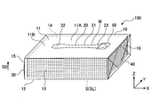
- FIG. 1 is a diagram showing a sheet package according to the embodiment.
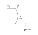
- FIG. 2 is a view of the sheet package of FIG. 1 as viewed from above
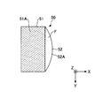
- FIG. 3 is a view showing an outlet and a knob in the sheet package of FIG. 4 is an enlarged view of the knob of FIG. 3
- FIG. 5 is a view of the knob of FIG. 4 in the Z direction
- FIG. 6 is a view of the knob of FIG. 4 in the Y direction.
- FIG. 7 is a view in which the outlet is opened in the sheet package of FIG.
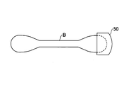
- FIG. 8 is a diagram showing fragments generated after the outlet is opened in the sheet package of FIG. 1.
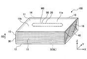
- the sheet package 100 according to the present embodiment has a packaging bag 10 and an outlet 20.
- the sheet package 100 is an example of the sheet package according to the present invention.
- the packaging bag 10 is an example of a packaging bag constituting the sheet packaging body according to the present invention
- the outlet 20 is an example of an outlet formed in the packaging bag.
- the packaging bag 10 accommodates a plurality of (or a plurality of sets) of laminated sheets S (hereinafter referred to as sheet laminated body SL).
- the sheet laminate SL is housed in the packaging bag 10 so that the stacking direction (SD direction) of the sheets S is the height direction (Z direction).
- the sheets S can be pulled out one by one (or one set at a time) through the outlet 20 (opening OP) formed in the packaging bag 10 (see FIG. 7).
- the form of the sheet laminated body SL is not particularly limited, and for example, each sheet S is alternately laminated in a folded state (so-called pop-up type sheet laminated body SL), or a plurality of sheets (or a plurality of sets). Examples thereof include those in which S is simply laminated, those in which each sheet S is laminated in a folded state, and the like. From the viewpoint of pulling out the sheets S one by one or one set at a time, the form of the sheet laminated body SL is preferably a pop-up type sheet laminated body SL.
- the dimensions of the sheet laminate SL are such that the length of the sheet package 100 in the first direction (X direction) is 80 mm or more and 250 mm or less, and the depth direction (Y) orthogonal to the first direction (X direction) of the sheet package 100.
- the length in the direction) can be 50 mm or more and 130 mm or less, and the height in the height direction (Z direction) can be 10 mm or more and 90 mm or less.
- Such a sheet laminate can be manufactured, for example, by a rotary type or a multi-stand type interfolder.
- the use of the sheet S is not particularly limited, and can be applied to, for example, sanitary tissue paper such as tissue paper, toilet paper, kitchen paper, and paper towel. These hygienic tissue papers also include hygienic tissue papers containing moisturizing ingredients (eg, lotion tissue paper, etc.).
- the use of the sanitary tissue paper constituting the sheet S is not particularly limited, and can be applied to any of industrial, household, and portable use. Among these, the sheet package 100 of the present embodiment is preferably used for household tissue paper.
- the number of plies of the sheet S can be 1 ply or more, preferably 1 ply, and more preferably 2 plies (two layers).
- the shape of the sheet S is not particularly limited, and for example, it is preferable that the shape of the two-ply sheet in a folded state is rectangular in a plan view.
- the material of the sheet S is not particularly limited, and for example, a sheet such as paper, non-woven fabric, or cloth can be used, and a paper sheet (hereinafter referred to as a paper sheet) is preferable.
- a paper sheet a paper sheet
- a base paper containing pulp as a main raw material is used.
- the pulp composition a known composition in a paper sheet can be used.
- the blending ratio of pulp can be 50% by mass or more, preferably 90% by mass or more, and more preferably 100% by mass.
- the pulp composition of the sheet S is not particularly limited.
- softwood pulp such as NBKP (softwood kraft pulp) and NUKP (unbleached softwood pulp) and hardwood pulp such as LBKP (hardwood kraft pulp) and LUKP (hardwood unbleached pulp) may be used in an arbitrary ratio. Can be done.
- the ratio of softwood pulp to hardwood pulp is not limited, but is preferably 10:90 to 80:20, and more preferably the ratio of softwood pulp to hardwood pulp is higher.
- used paper pulp may be used as the pulp contained in the sheet S (paper sheet).
- the basis weight of the sheet S is not particularly limited, depending on number of plies, in the case of paper 5 g / m 2 or more 80 g / m 2 or less, those of 20 g / m 2 or more 100 g / m 2 or less in the case of non-woven fabric desirable.
- the basis weight can be measured in accordance with the provisions of JIS P 8124.
- the thickness of the sheet S is not particularly limited, and the paper thickness measured in the environment of JIS P 8111 (1998) can be adopted.
- the paper thickness of the paper sheet constituting the sheet S can be 50 ⁇ m or more and 500 ⁇ m or less, preferably 60 ⁇ m or more and 330 ⁇ m or less per 2 plies.
- the sheet S (paper sheet) may be embossed.
- embossing can be carried out by a known embossing method.
- the packaging mode of the packaging bag 10 is not particularly limited.
- packaging in which both ends of a tubular flexible film are folded and sealed (sealed), both ends of a tubular flexible film folded in a gusset shape, or any of them.
- Use packaging that seals (seals) one end prlow packaging
- packaging that heats a heat-shrinkable resin film to bring it into close contact with the object to be packaged (shrink packaging), or packaging that combines these. be able to.
- the sheet laminate SL is caramel-wrapped. Specifically, the side surfaces 15 and 16 of the packaging bag 10 are folded and sealed. As a result, the seal portion 30 is formed on the side surface 15 of the packaging bag 10, and the seal portion 40 is formed on the side surface 16 (see FIG. 1).
- the sheet laminate SL is wrapped with a flexible film so as to be wound into a tubular shape so that both ends in the longitudinal direction (X direction) are opened, and the portion overlapping in the winding direction is fused.
- glue with an adhesive. Fold both ends of the tubular flexible film in the longitudinal direction (X direction) toward both end faces of the sheet laminate SL, and at least the tip edges of the substantially triangular or substantially trapezoidal pieces formed at that time.
- Each opening of the tubular flexible film is sealed by stacking and adhering by a fusion treatment or an adhesive (see FIG. 1).
- the material of the flexible film forming the packaging bag 10 is not particularly limited, and for example, polyethylene (PE), polypropylene (PP), polyethylene terephthalate (PET), polystyrene (PS), polyvinyl chloride (PVC). , Ethylene-vinyl acetate copolymer (EVA), polypropylene (PA) and other resins can be used.
- PE polyethylene
- PP polypropylene
- PET polyethylene terephthalate
- PS polystyrene
- PVC polyvinyl chloride
- EVA Ethylene-vinyl acetate copolymer
- PA polypropylene
- polyethylene, polypropylene, polyethylene terephthalate and the like are preferable from the viewpoints of being flexible, excellent in handleability, high sealing property when heat-sealed, and inexpensive. Further, polyethylene is preferable from the viewpoint of being odorless, excellent in water resistance and chemical resistance, and capable of mass production at low cost. As the polyethylene, high-density polyethylene, low-density polyethylene and the like can be used. Further, polypropylene is preferable from the viewpoints of being robust, easy to mold, good color development at the time of printing, and being able to impart gloss.
- the form of the flexible film forming the packaging bag 10 is not particularly limited, and is a single-layer film in which the above-mentioned resin is formed in a single layer, a laminate film in which the above-mentioned resin is laminated, or the above-mentioned two or more kinds of resins. It may be a mixed film formed of a mixture of.
- the thickness of the flexible film forming the packaging bag 10 is not particularly limited, and is preferably 20 ⁇ m or more and 100 ⁇ m or less, and more preferably 25 ⁇ m or more and 70 ⁇ m or less. By setting the thickness of the flexible film to 20 ⁇ m or more, sufficient strength as a packaging bag 10 in which the sheet S is housed can be ensured. Further, by setting the thickness of the flexible film to 100 ⁇ m or less, the flexibility and lightness of the packaging bag 10 can be ensured, and the cost can be suppressed.
- the material for forming the packaging bag 10 is not limited to the resin material such as the flexible film described above, and a paper material may be used.
- the materials forming the packaging bag 10 include biodegradable materials (biodegradable plastics, biodegradable paper, etc.) and biomass materials (renewable biological organic resources such as biomass film, excluding fossil resources). ) Can be used.
- the packaging bag 10 has a top surface 11, a bottom surface 12, a front surface 13, a back surface 14, a side surface 15, and a side surface 16.
- the top surface 11 and the bottom surface 12 face each other in the vertical direction (Z direction)
- the front surface 13 and the back surface 14 face each other in the front-rear direction (Y direction)
- the side surface 15 and the side surface 16 face each other in the left-right direction (X direction).
- the side surface 15 and the side surface 16 are continuous with any of the top surface 11, the bottom surface 12, the front surface 13, and the back surface 14 (see FIG. 1).
- the outlet 20 is formed so as to open to the top surface 11 of the packaging bag 10.
- the outlet 20 corresponds to a part region R of the top surface 11, and is the center 11A and the second direction of the top surface 11 of the packaging bag 10 in the first direction (X direction) of the sheet package 100. It is arranged at the center 11B of the top surface 11 of the packaging bag 10 in the (Y direction) (see FIGS. 1 and 2).
- a part of the top surface 11 indicates a portion (a portion corresponding to the region R) in a range smaller than half of the top surface 11.
- the top surface 11 is provided with a perforation M that surrounds a part of the region R of the top surface 11, and when the perforation M is cleaved, the outlet 20 opens (FIG. 6). 1 to 3 and 7).
- the perforation M the cut C and the tie T (the uncut portion between the two cuts C) are alternately arranged, and when the tie T breaks, the cuts C on both sides become continuous cuts for cleavage. The line of sight is shown (see FIGS. 1 to 3).
- the region R surrounded by the perforation M (hereinafter, may be referred to as the perforation region R) intersects a given length L2 extending in the first direction (X direction) and the first direction (X direction). It has a given width W2 that extends in the second direction (Y direction).
- the first direction (X direction) indicates a direction (longitudinal direction or left-right direction of the sheet package 100) along a predetermined one direction on the top surface 11 of the packaging bag 10.
- the second direction (Y direction) intersecting with the first direction (X direction) is a direction orthogonal to a direction along a predetermined one direction on the top surface 11 of the packaging bag 10 or a direction along a direction intersecting the streaks. (The lateral direction or the depth direction of the sheet package 100) is shown.
- the dimension of the outlet 20 (the length L2 of the perforation region R) can be arbitrarily determined according to the capacity of the packaging bag 10 and the dimension of the sheet S.
- the length L2 of the perforation region R can be 100% or less, preferably 5% or more, with respect to the width (length L1) of the top surface 11 of the packaging bag 10 in which the sheet S is housed. It is 80% or less, more preferably 10% or more and 75% or less (see FIG. 2).
- the dimension of the outlet 20 can be arbitrarily determined according to the capacity of the packaging bag 10 and the dimension of the sheet S.
- the width W2 of the perforation region R can be 1% or more and 25% or less, preferably 3% or more and 20% or less, with respect to the vertical width (width W1) of the top surface 11 of the packaging bag 10. More preferably, it is 5% or more and 15% or less (see FIG. 2).
- the perforation region R has a base portion 21 and end portions 22 and 23 (see FIGS. 2 and 3).
- the base portion 21 is a substantially rectangular region or a substantially rectangular region existing between two linear perforations M1 facing the lateral direction (Y direction) of the sheet package 100 and extending substantially parallel to the longitudinal direction (X direction).
- the perforation M1 constituting the base 21 of the perforation region R is a perforation in which the cut C1 and the tie T1 are alternately arranged (see FIG. 3).
- the ends 22 and 23 are continuous with the ends 21A and 21B of the base 21, and are surrounded by the eggplant-shaped perforations M2 and M3 and the ends 21A and 21B of the base 21, respectively, in a dumbbell-shaped region or range. Is.
- the perforations M2 constituting the ends 22 and 23 of the perforation region R are perforations in which the cut C2 and the tie T2 are alternately arranged (see FIG. 3).
- the dimension of the outlet 20 (width W3 of the perforation area R) can be arbitrarily determined according to the capacity of the packaging bag 10 and the dimension of the sheet S.
- the width W3 of the perforation region R can be 5% or more and 35% or less, preferably 10% or more and 30% or less, with respect to the vertical width (width W1) of the top surface 11 of the packaging bag 10. More preferably, it is 15% or more and 25% or less (see FIG. 2).
- the width of the base 21 in the second direction (Y direction) corresponds to the width W2 of the perforation region R described above (see FIG. 2). Further, the maximum widths of the ends 22 and 23 in the second direction (Y direction) correspond to the width W3 of the perforation region R (see FIG. 2).
- the length of the cut C1 and the length of the tie T1 are arbitrary.
- the length of each cut C1 can be 0.8 mm or more and 5 mm or less, preferably 1.5 mm or more and 4.5 mm or less, and more preferably 2.5 mm or more and 4 mm or less.
- the length of each tie T1 can be 0.3 mm or more and 5 mm or less, preferably 0.4 mm or more and 2 mm or less, and more preferably 0.5 mm or more and 1.5 mm or less.
- the length of the cut C2 and the length of the tie T2 are arbitrary.
- the length of each cut C2 can be 0.8 mm or more and 5 mm or less, preferably 1.5 mm or more and 4.5 mm or less, and more preferably 2.5 mm or more and 4 mm or less.
- the length of each tie T2 can be 0.3 mm or more and 5 mm or less, preferably 0.4 mm or more and 2 mm or less, and more preferably 0.5 mm or more and 1.5 mm or less.
- the width W2 narrows from both end portions 22 and 23 in the first direction (X direction) of the region R toward the center 24 side of the region R.
- the perforation region R has a width W2 in the second direction (Y direction) of the region R widening from the center 24 side in the first direction (X direction) toward both end portions 22 and 23. That is, both end portions 22 and 23 of the perforation region R extend from the width W2 to the width W3 (see FIGS. 1 to 3).
- the linear perforations M1 constituting the base portion 21 of the perforation region R are the edge edges E1 and E2 of the perforation region R facing the second direction (Y direction). Further, a part of the eggplant-shaped perforations M2 and M3 constituting the end portions 22 and 23 of the perforation region R, respectively, is formed on the edge E3 and E4 of the perforation region R facing the first direction (X direction). Corresponds (see FIG. 3).
- both end edges E3 and E4 of the perforation region R in the first direction (X direction) have an arc shape that is convex to the outer OR of the region R.
- having a convex arc shape means that the end edges E3 and E4 are curved in a convex shape.
- a part of the perforations M2 constituting both end edges E3 and E4 of the perforation region R is composed of two arcuate cuts C2, and the two cuts C2 are connected by one tie T2. (See FIG. 3).
- the shape of the perforations M2 constituting the both end edges E3 and E4 of the perforation region R is not limited to this embodiment.
- a part of the perforations M2 forming the both end edges E3 and E4 may be composed of three arcuate cuts C2 and two tie T2s connecting two adjacent cuts C2.
- a part of the perforations M2 forming the both end edges E3 and E4 may be formed by one cut C2 so that the tie T2 does not exist.
- a knob 50 is provided in the perforation area R (see FIGS. 1 to 6).
- the knob 50 indicates a portion or member that can be pinched by a fingertip or the like.
- the knob 50 is formed as a separate member from the packaging bag 10 (see FIGS. 1 to 6).
- the material of the knob 50 is not limited, and a resin material such as a flexible film (film F shown in FIGS. 4 to 6) used for the above-mentioned packaging bag 10, a paper material, a biodegradable material, a biomass material, and the like can be used. Can be used.
- the form of the knob 50 is not limited, and the single-layer film, the laminated film, and the mixed film used for the above-mentioned packaging bag 10 can be used. Further, as the thickness of the knob 50, the thickness of the flexible film used for the above-mentioned packaging bag 10 can be adopted.
- the knob 50 is provided at at least one end of the perforation region R in the first direction (X direction).
- the end portion of the region R in the first direction (X direction) indicates one end portion (end portion 22 or end portion 23) of the perforation region R in the first direction (X direction).
- the knob 50 is provided at the end 23 of the perforation region R.
- the knob 50 has an adhesive portion 51 and a non-adhesive portion 52.
- the adhesive portion 51 is a portion to be adhered to the perforation region R.
- the non-adhesive portion 52 is a portion that is not adhered to the region R.
- the knob 50 is composed of a substantially rectangular adhesive portion 51 and a bow-shaped non-adhesive portion 52.
- the non-adhesive portion 52 is adjacent to the adhesive portion 51 so that one side of the rectangle constituting the adhesive portion 51 overlaps the bow-shaped chord (a line segment connecting both ends of the arc) forming the non-adhesive portion 52. (See FIGS. 4 and 5).
- a part of the perforations M3 constituting the edge E4 of the perforation region R is entirely covered by the adhesive portion 51 of the knob 50 (FIGS. 2 and 3).
- the area ratio between the adhesive portion 51 and the non-adhesive portion 52 is not limited, but preferably the area ratio between the adhesive portion 51 and the non-adhesive portion 52 is 4: 1 to 8: 1, more preferably. It is 5: 1 to 7: 1 (see FIG. 5).
- the area ratio indicates the ratio between the area of the bonded portion 51 and the area of the non-bonded portion 52.
- the adhesive layer 51A is provided on the side of the adhesive portion 51 facing the perforation region R (the surface of the adhesive portion 51 when viewed in the Z direction) (see FIGS. 5 and 6).
- the material of the adhesive layer 51A is not particularly limited, but it is preferable that the adhesive force of the adhesive portion 51 is 2N / 25 mm or more and 6N / 25 mm or less.
- the adhesive strength indicates a peeling resistance value measured by an adhesive strength test method with reference to JIS Z0237.
- An adhesive can be used as a material having such adhesive strength.
- examples of such an adhesive include adhesives such as rubber-based adhesives, acrylic-based adhesives, silicone-based adhesives, and urethane-based adhesives.
- an acrylic pressure-sensitive adhesive is preferable from the viewpoint of less deterioration over time and less discoloration.
- these adhesives contain a curing agent.
- the curing agent include isocyanate-based curing agents, epoxy-based curing agents, aziricin-based curing agents, metal chelate-based curing agents, carbodiimide-based curing agents, and the like.
- an isocyanate-based curing agent used as a curing agent for an acrylic pressure-sensitive adhesive is preferable.
- these adhesives preferably contain a cross-linking agent.
- the cross-linking agent include epoxy-based cross-linking agents, isocyanate-based cross-linking agents, amine-based cross-linking agents, melamine-based cross-linking agents, aziridine-based cross-linking agents, aldehyde-based cross-linking agents, metal chelate-based cross-linking agents, acid anhydride-based cross-linking agents, and the like.
- an epoxy-based cross-linking agent used as a cross-linking agent for an acrylic pressure-sensitive adhesive is preferable.
- the portion corresponding to the non-adhesive portion 52 is covered with a film, printing, or the like to cover the adhesive portion 51 with the adhesive layer 51A.
- the mode of forming the adhesive layer 51A on the adhesive portion 51 is not limited to this, and for example, such an adhesive may be applied to the adhesive portion 51 of the knob 50 to form the adhesive layer 51A.
- the shape of the non-adhesive portion 52 of the knob 50 is not limited, but it is preferable to have an arc-shaped free end 52A (see FIGS. 1 to 6).
- the free end 52A indicates that the end edge 52A of the non-adhesive portion 52 is not fixed.
- the knob 50 is not limited to the case where the entire adhesive portion 51 is adhered to the inner IR of the region R. That is, a part 51B of the adhesive portion 51 may be adhered to the outer OR of the region R (see FIGS. 1 to 3).
- the part 51B of the adhesive portion 51 indicates a portion in a range less than half of the adhesive portion 51.
- the knob 50 is provided in a part of the region (perforation region) R of the top surface 11 surrounded by the perforations M, so that when the knob 50 is pinched and pulled up, the sewing machine The eye M is cleaved to produce a fragment B to which the knob 50 is attached (see FIGS. 7 and 8).
- the outlet 20 opens in the portion of the top surface 11 corresponding to the perforation region R (the opening OP can be formed in the top surface 11 of the packaging bag 10).
- the sheet package 100 in which the outlet 20 (opening OP) can be easily formed can be obtained.
- the knob 50 has an adhesive portion 51 that adheres to the perforation region R and a non-adhesive portion 52 that does not adhere to the perforation region R, so that the adhesive portion 51 of the knob 50 has a perforation region. While fixed to R (inner IR), the non-adhesive portion 52 of the knob 50 can be pinched with a fingertip. Therefore, according to the present embodiment, the knob 50 is easy to pinch and pull.
- the knob 50 is fixed to the perforation region R (inner IR) by adopting the knob 50 in which the area ratio of the bonded portion 51 and the non-bonded portion 52 is within the above range. While maintaining the state, the knob 50 becomes easier to pinch and pull up.
- the knob 50 is packaged at the time of manufacturing the sheet package 100 by allowing a configuration in which a part 51B of the adhesive portion 51 of the knob 50 is adhered to the outer OR of the perforation region R.
- the knob 50 can be easily attached.
- the portion of the adhesive portion 51 having a region larger than half is fixed to the perforation region R (inner IR)
- the knob 50 when the knob 50 is pinched and pulled up, the knob 50 becomes the perforation region R.
- the perforation M is cleaved, and a part 51B of the adhesive portion 51 that adheres to the outer OR of the perforation region R is peeled off. Therefore, in the present embodiment, even if a part 51B of the adhesive portion 51 is adhered to the outer OR of the perforation region R, the outlet 20 can be opened to the top surface 11.
- the knob 50 having the adhesive portion 51 having the adhesive strength of 2N / 25 mm or more and 6N / 25 mm or less is provided in the perforation region R, so that when the knob 50 is pinched and pulled up, the knob 50 is pinched.
- the perforation M can be cleaved with the 50 fixed in the perforation region R (inner IR). Thereby, in the present embodiment, the outlet 20 can be easily opened.
- the perforation M is cleaved while the knob 50 is adhered in the inner IR of the perforation region R.
- a part 51B of the adhesive portion 51 that adheres to the outer OR of the perforation region R can be peeled off.
- the knob 50 is more easily pinched and pulled up more easily.
- W2 the contour shape of the perforation region R becomes an elongated shape in which the first direction (X direction) is the longitudinal direction and the second direction (Y direction) is the width direction.
- the knob 50 is provided at at least one end (end 23) of the perforation region R in the first direction (X direction), the knob 50 is provided along the first direction (X direction). It is easy to pull toward the end (end 22) side of the.
- the knob 50 when the knob 50 is pulled toward the other end (end 22) along the first direction (X direction), the perforation M is cleaved and corresponds to the perforation region R.
- the elongated outlet 20 can be opened.
- the knob 50 is provided at the end portion 23 of the perforation region R so that the adhesive portion 51 covers a part of the perforation M2 constituting the end edge E4 of the perforation region R. Therefore, it is difficult for the end portion 23 of the perforation region R to be rolled from the cut C2 of the perforation M2. Therefore, it is possible to prevent the perforations M from being cleaved at the time of manufacturing or selling the sheet package.
- the width of the perforation region R is narrowed from both end portions 22 and 23 in the first direction (X direction) toward the center 24 side, so that the perforation region R is in the longitudinal direction.
- the knob 50 provided at the end portion 23 of the above is pinched and pulled toward the center 24, the perforation M is likely to be cleaved from the end portion 23 in the longitudinal direction toward the center 24. This makes it easier to form the outlet 20 in the present embodiment.
- the width of the outlet 20 that opens to the top surface 11 is wider on both end portions 22 and 23 than on the central 24 side of the outlet 20. Therefore, when the sheet S is pulled out, the sheet S is less likely to be clogged at both ends 22 and 23 of the outlet 20 which is easily clogged and easily broken, and the sheet S can be suppressed from being broken. As a result, in the present embodiment, the sheet package 100 having more excellent take-out property can be obtained.
- both end edges E3 and E4 in the first direction (X direction) have an arc shape that is convex to the outer OR of the perforation region R
- the knob 50 is pinched and pulled up.
- the edge E4 on the end portion 23 side in the longitudinal direction of the perforation region R provided with the knob 50 is easily cleaved.
- the edge E3 on the end 22 side in the longitudinal direction of the perforation region R in which the knob 50 is not provided is also easily cleaved. This further facilitates the formation of the outlet 20 in the present embodiment.
- both end edges E3 and E4 of the outlet 20 opening to the top surface 11 in the longitudinal direction can be curved toward the outside of the outlet 20. Therefore, the rubbing of the sheet S is alleviated at both end portions 22 and 23 of the outlet 20 where the sheet S is easily clogged and easily broken when the sheet S is pulled out. As a result, the sheet S is less likely to be clogged, and breakage of the sheet S can be suppressed. In this way, in the present embodiment, the sheet package 100 having further excellent take-out property can be obtained.
- the sheet laminated body SL is a tissue paper (basis weight: 12 g / m 2 , paper thickness: 130 ⁇ m, number of plies: 2 plies, number of pairs) laminated so that the sheets S can be folded alternately and pulled out one by one in a pop-up manner. : 120 sets (240 sheets), dimensions: height about 40 mm, width about 178 mm, length about 100 mm) were used (see FIG. 7).
- the sheet laminated body SL was housed in the packaging bag 10 so that the laminating direction (SD direction) was the height direction (Z direction) of the sheet packaging body 100 (see FIG. 1).
- the material of the packaging bag 10 polyethylene (PE) having a thickness of 60 ⁇ m and having a satin-finished surface was used.
- both side surfaces 15 and 16 of the sheet packaging body 100 are sealed with caramel packaging (seal portions 30 and 40 are formed).
- the dimensions of the packaging bag 10 were a length L1 of about 180 mm in the first direction (X direction), a width W1 of about 100 mm in the depth direction (Y direction), and a height of about 40 mm in the height direction (Z direction).
- a perforation M was formed on the top surface 11 of the packaging bag 10 so that the outlet 20 opens when the packaging bag 10 is cleaved.
- Label (test sample) As a test sample corresponding to the knob, a label (PET film having a thickness of 50 ⁇ m) coated with an adhesive was prepared.
- the test sample As the adhesive strength of the knob (test sample), the test sample (adjusted to a width of 25 mm and a length of 300 mm) was subjected to an adherend (polyethylene film, stainless steel plate (SUS)), and an adherend (polyethylene film, stainless steel plate (SUS)) by an adhesive strength measuring method with reference to JIS Z0237.
- adherend polyethylene film, stainless steel plate (SUS)
- adherend polyethylene film, stainless steel plate (SUS)
- peeling force of the knob As the peeling force of the knob (test sample), the above-mentioned adhesive force measurement (adhesion is polyethylene film only, the adherend is polyethylene film only) for the test sample (adjusted to width 50 mm and length 300 mm) by the adhesive force measuring method based on JIS Z0237. The resistance value was measured in the same manner as (only after leaving for 20 minutes) to obtain a peeling force (low speed). Similar to the above-mentioned measurement of adhesive strength, after the test sample is attached to the adherend (polyethylene film), the attached test sample is prepared using a high-speed peeling tester (TE-701 manufactured by Tester Sangyo Co., Ltd.).
- TE-701 manufactured by Tester Sangyo Co., Ltd.
- the resistance value when peeling from the adherend at a speed of 0.3 m / min in the 180 ° direction is measured and the peeling force (low speed), and the resistance value when peeling at a speed of 60 m / min is measured and the peeling force (high speed).
- the unit of peeling force is mN / 50 mm.
- the peeling force (low speed) was evaluated as good in the range of 120 to 200 mN / 50 mm and poor in the range outside the range.
- the peeling force (high speed) was evaluated as good in the range of 450 to 600 mN / 50 mm and poor in the range outside the range.
- Label peeling As the label peeling, it was confirmed whether or not the label was peeled off after the label (test sample) was attached to the adherend (glassine paper) and then left for 20 minutes and 24 hours. The label peeling was evaluated according to the following criteria, with ⁇ being good and ⁇ and ⁇ being bad. ⁇ : Did not peel off ⁇ : Peeled off ⁇ : Peeled off before leaving for 20 minutes
- sensuality As a sensuality, the label was attached to the end portion 23 of the perforation region R of the sheet package 100 as a knob, and the ease of opening after leaving for 24 hours was evaluated. The evaluation of sensuality was performed according to the following criteria, and 3 or more was good and 2 or less was bad. 5: Very easy to open 4: Easy to open 3: Can be opened 2: Slightly difficult to open 1: Difficult to open
- Example 1 A part of the region R of the top surface 11 of the packaging bag 10 corresponding to the outlet 20 is surrounded by perforations M (perforations M1, M2, M3), and both end portions 22 and 23 of the perforations region R are in the first direction (perforations M1, M2, M3).
- An arc shape that widens from the center 24 side in the X direction) toward both end portions 22 and 23, and both end edges E3 and E4 in the first direction (X direction) of the perforation area R are convex to the outer OR of the area R.
- a knob 50 is provided at the end 23 of the perforated region R having a shape (dumbbell type), and a part 51B of the adhesive portion 51 of the knob 50 is adhered to the outer OR of the perforated region R. (See FIGS. 1 to 6), the openability, the removability, and the sheet tear were evaluated. The results are shown in Table 1.
- Example 1 The evaluation was performed in the same manner as in Example 1 except that the outlet 20 was formed only by a linear slit (perforation M4) (see FIG. 9). The results are shown in Table 1.
- Example 2 The evaluation was performed in the same manner as in Example 1 except that the outlet 20 was formed only by a substantially elliptical slit (perforation M5) (see FIG. 10). The results are shown in Table 1.
- Example 1 For test samples coated with an acrylic pressure-sensitive adhesive (containing 0.3% isocyanate-based curing agent and epoxy-based cross-linking agent) as an adhesive, adhesive strength, peeling power, ball tack, label peeling, and stretching / tearing of the package film , Perforation breakage and functionality were evaluated. The results are shown in Table 2. The conditions of Experimental Example 1 correspond to the conditions of the knob 50 in the sheet package 100 (test body) of Example 1.
- an acrylic pressure-sensitive adhesive containing 0.3% isocyanate-based curing agent and epoxy-based cross-linking agent
- Example 3 As the adhesive, the content of the isocyanate-based curing agent of the acrylic pressure-sensitive adhesive was 2.4%, and the evaluation was carried out in the same manner as in Experimental Example 1 except that the isocyanate-based cross-linking agent was used instead of the epoxy-based cross-linking agent. The results are shown in Table 1.
- both end portions 22 and 23 become wider from the center 24 side in the first direction (X direction) toward both end portions 22 and 23 side, and both end edges E3 and E4 in the first direction (X direction) are regions R.
- the sheet package 100 provided with the knob 50 at the end 23 of the perforation region R having an arc shape convex to the outer OR of the sheet package 100 was good in opening property, take-out property, and sheet tearing (Example). 1).
- the slit (perforation M4) having a linear outlet 20 was poor in openability, take-out property, and sheet tear (Comparative Example 1). Further, the sheet package 100 formed by the substantially elliptical slits (perforations M5) had poor openability (Comparative Example 2).
- labels coated with an acrylic pressure-sensitive adhesive (containing 0.5% isocyanate-based curing agent and epoxy-based cross-linking agent) as an adhesive have the label peeled off after 20 minutes and the perforations are poorly broken.
- acrylic pressure-sensitive adhesive (containing 2.4% isocyanate-based curing agent and isocyanate-based cross-linking agent), acrylic pressure-sensitive adhesive (containing 3.5% isocyanate-based curing agent and isocyanate-based cross-linking agent) and acrylic as adhesives.
- the label coated with the adhesive (containing 3.9% of isocyanate-based curing agent and isocyanate-based cross-linking agent) had a torn package film after 24 hours and had poor functionality (Experimental Examples 3 to 5).
- the first aspect according to the present invention has a packaging bag for accommodating a plurality of laminated sheets and an outlet that opens to the top surface of the packaging bag, and the top surface has the top surface of the packaging bag.
- a part of the top surface means a part in a range less than half of the top surface.
- the perforation indicates a cleavage line in which cuts and ties (the uncut portion between the two cuts) are alternately arranged, and when the ties are broken, the cuts on both sides become continuous cuts.
- the knob indicates a portion or member that can be pinched by a fingertip or the like.
- a knob is provided in a part of the top surface surrounded by the perforation (hereinafter, may be referred to as a perforation area), and when the knob is pinched and pulled up, the perforation is cleaved. Then, the outlet can be opened in the portion corresponding to the perforated area on the top surface. Therefore, according to the first aspect, it is possible to provide a sheet package in which an outlet can be easily formed.
- a second aspect according to the present invention is a sheet package in which the knob has an adhesive portion that is adhered to the region and a non-adhesive portion that is not adhered to the region.
- the knob has an adhesive portion that adheres to the perforation region and a non-adhesive portion that does not adhere to the perforation region, so that the adhesive portion of the knob is fixed to the perforation region and the knob is not adhered. You can pinch the part with your fingertips. Therefore, according to the second aspect, the knob is easy to pick up and pull up.
- a third aspect according to the present invention is a sheet package in which the knob has an area ratio of 4: 1 to 8: 1 between the adhesive portion and the non-adhesive portion.
- the area ratio indicates the ratio between the area of the bonded portion and the area of the non-bonded portion.
- a fourth aspect according to the present invention is a sheet package in which a part of the adhesive portion is adhered to the outside of the region.
- a part of the bonded portion means a portion in a range less than half of the bonded portion.
- a configuration in which a part of the adhesive portion of the knob is adhered to the outside of the perforation region is allowed, so that when the knob is attached to the packaging bag as a separate member at the time of manufacturing the sheet package, the knob Installation work becomes easy.
- the sewing machine since the portion of the adhesive portion more than half is fixed to the perforation region, the sewing machine is in a state where the knob is fixed to the perforation region when the knob is pinched and pulled up. The eye is cleaved and part of the adhesive that adheres to the outside of the perforation area is peeled off. Therefore, in the fourth aspect, the outlet can be opened to the top surface even if a part of the bonded portion is bonded to the outside of the perforated region.
- a fifth aspect according to the present invention is a sheet package in which the adhesive strength of the adhesive portion is 2N / 25 mm or more and 6N / 25 mm or less.
- the adhesive strength indicates a peeling resistance value measured by an adhesive strength test method with reference to JIS Z0237.
- the knob by providing a knob having an adhesive portion having an adhesive force of 2N / 25 mm or more and 6N / 25 mm or less in the perforated region, the knob is fixed to the perforated region when the knob is pinched and pulled up. In the state, the perforations can be cleaved. Thereby, in the fifth aspect, the outlet can be easily opened.
- the perforation is cleaved inside the perforation region while the knob is adhered, and the perforation is to the outside of the perforation region.
- a part of the adhesive portion to be adhered can be peeled off.
- a sixth aspect according to the present invention is a sheet package in which the non-adhesive portion has an arc-shaped free end.
- the free end means that the edge of the non-adhesive portion is not fixed.
- the non-adhesive portion of the knob since the non-adhesive portion of the knob has an arcuate free end, the knob is more easily pinched and pulled up more easily.
- a seventh aspect of the invention is that the region has a given length extending in a first direction and a given width extending in a second direction intersecting the first direction.
- the first direction indicates a direction along a predetermined direction on the top surface of the packaging bag.
- the second direction intersecting with the first direction indicates a direction orthogonal to a direction along a predetermined one direction on the top surface of the packaging bag or a direction along a direction intersecting the streaks.
- the end portion in the first direction of the region refers to one end portion in the first direction of the perforation region.
- the contour shape of the perforated region is longitudinal in the first direction by having a given length extending in the first direction and a given width extending in the second direction intersecting the first direction. It has an elongated shape with the second direction being the width direction. Further, since the knob is provided at at least one end of the perforation region in the first direction, the knob can be easily pulled toward the other end along the first direction.
- the perforation when the knob is pulled toward the other end side along the first direction, the perforation can be cleaved to open an elongated outlet corresponding to the perforation region. ..
- the perforation can be cleaved to open an elongated outlet corresponding to the perforation region. ..
- An eighth aspect according to the present invention is a sheet package in which the width of the region narrows from both ends of the region in the first direction toward the center of the region.
- the width narrowing from both end sides in the first direction of the region toward the center side means that the width of the perforation region in the second direction widens from the center side in the first direction toward both ends. Is shown.
- the width of the perforation region is narrowed from both end sides in the first direction toward the center side in this way, so that the knobs provided at the end portions in the longitudinal direction of the perforation region are pinched.
- the perforation is likely to be cleaved from the end in the longitudinal direction toward the center.
- the width of the outlet that opens to the top surface is wider on both ends than the center side of the outlet. Therefore, when the sheet is pulled out, the sheet is less likely to be clogged at both ends of the outlet where the sheet is easily clogged and easily broken, and the sheet can be suppressed from being broken. As a result, in the eighth aspect, a sheet package having more excellent take-out property can be obtained.
- a ninth aspect according to the present invention is a sheet package in which the region has an arc shape in which both end edges of the region in the first direction are convex to the outside of the region.
- the both end edges of the region in the first direction indicate each end edge facing the first direction of the perforation region.
- Having a convex arc shape means that each edge is curved in a convex shape.
- the edges of both ends in the first direction have an arc shape that is convex to the outside of the perforation region, so that when the knob is pinched and pulled up, the knob is provided in the longitudinal direction of the perforation region.
- the edge on the edge side is easily cleaved.
- the edge on the end side in the longitudinal direction of the perforated region where the knob is not provided is also likely to be cleaved. This further facilitates the formation of the outlet in the ninth aspect.
- both ends of the outlet opening in the top surface in the longitudinal direction can be curved toward the outside of the outlet. Therefore, the rubbing of the sheet is alleviated at both ends of the outlet where the sheet is easily clogged and broken when the sheet is pulled out. As a result, the sheet is less likely to be clogged, and breakage of the sheet can be suppressed. Therefore, in the ninth aspect, a sheet package having further excellent take-out property can be obtained.
Landscapes
- Engineering & Computer Science (AREA)
- Mechanical Engineering (AREA)
- Health & Medical Sciences (AREA)
- Public Health (AREA)
- Packages (AREA)
- Containers And Packaging Bodies Having A Special Means To Remove Contents (AREA)
Abstract
積層された複数枚のシートを収容する包装袋と、前記包装袋の天面に開口する取出口とを有し、前記天面には、前記天面の一部の領域を囲み且つ開裂して前記取出口を構成するミシン目が設けられ、前記領域には、つまみが設けられている、シート包装体。
Description
本発明は、シート包装体に関する。
ティシューペーパー等の衛生薄葉紙は、厚紙の箱に収容されたカートンタイプのシート包装体が普及しているが、運搬、保管、廃棄、環境負荷、コスト等の観点から、近年、フィルム状の包装袋に収容されたソフトパックタイプのシート包装体の需要が高まっている。ソフトパックタイプのシート包装体は、包装袋の天面にシートを取り出すための取出口(ミシン目等が開裂した開口)が設けられている(例えば、特許文献1、2参照)。
本発明の課題は、取出口の形成が容易なシート包装体を提供することである。
本発明に係る第1の態様は、積層された複数枚のシートを収容する包装袋と、前記包装袋の天面に開口する取出口とを有し、前記天面には、前記天面の一部の領域を囲み且つ開裂して前記取出口を構成するミシン目が設けられ、前記領域には、つまみが設けられている、シート包装体である。
本発明の一態様によれば、取出口の形成が容易なシート包装体を提供することができる。
本発明の実施の形態について、図面を参照しながら詳細に説明する。なお、各図において、共通する部分については、同一の符号を付して説明を省略する場合がある。また、各図において、各部材の縮尺は実際とは異なる場合がある。
本明細書では、3軸方向(X方向、Y方向、Z方向)の3次元直交座標系を用い、シート包装体の長手方向または左右方向(以下、第1方向という)をX方向とし、短手方向または奥行き方向(以下、第2方向という)をY方向とし、高さ方向または上下方向をZ方向とする。また、上方とは、シート包装体の高さ方向(Z方向)において、包装袋の天面の上側を示す。
図1は、実施形態に係るシート包装体を示す図である。図2は、図1のシート包装体を上方から見た図であり、図3は、図1のシート包装体において、取出口とつまみを示す図である。図4は、図3のつまみを拡大した図であり、図5は、図4のつまみをZ方向に見た図であり、図6は、図4のつまみをY方向に見た図である。図7は、図1のシート包装体において、取出口が開口した図である。図8は、図1のシート包装体において、取出口が開口した後に発生する破断片を示す図である。
本実施形態に係るシート包装体100は、図1に示すように、包装袋10および取出口20を有する。シート包装体100は、本発明に係るシート包装体の一例である。また、包装袋10は、本発明に係るシート包装体を構成する包装袋の一例であり、取出口20は、該包装袋に形成される取出口の一例である。
包装袋10には、図1に示すように、積層された複数枚(または複数組)のシートS(以下、シート積層体SLという)が収容される。シート積層体SLは、シートSの積層方向(SD方向)が高さ方向(Z方向)となるように、包装袋10に収容されている。シート積層体SLは、包装袋10に形成される取出口20(開口OP)を通してシートSが1枚ずつ(または1組ずつ)引き出せるようになっている(図7参照)。
シート積層体SLの形態は、特に限定されず、例えば、各シートSが折り込まれた状態で互い違いに積層されたもの(いわゆるポップアップ式のシート積層体SL)、複数枚(または複数組)のシートSが単に積層されたもの、各シートSが折り畳まれた状態で積層されたもの等が挙げられる。なお、シートSを1枚または1組ずつ引き出す観点から、シート積層体SLの形態は、ポップアップ式のシート積層体SLが好ましい。
また、シート積層体SLの寸法は、シート包装体100の第1方向(X方向)の長さを80mm以上250mm以下、シート包装体100の第1方向(X方向)に直交する奥行方向(Y方向)の長さを50mm以上130mm以下、高さ方向(Z方向)の高さを10mm以上90mm以下とすることができる。このようなシート積層体は、例えば、ロータリー式又はマルチスタンド式インタフォルダによって製造することができる。
シートSの用途は、特に限定されず、例えば、ティシューペーパー、トイレットペーパー、キッチンペーパー、ペーパータオル等の衛生薄葉紙に適用可能である。これらの衛生薄葉紙には、保湿成分を含んだ衛生薄葉紙(例えば、ローションティシュー等)も含まれる。また、シートSを構成する衛生薄葉紙の用途は、特に限定されず、産業用、家庭用、携帯用のいずれにも適用できる。なお、本実施形態のシート包装体100は、これらの中でも、家庭用のティシューペーパーに好適に用いられる。
シートSのプライ数は、1プライ以上にすることができ、好ましくは1プライ、より好ましくは2プライ(2枚重ね)である。また、シートSの形状は、特に限定されず、例えば、2プライのシートが折り畳まれた状態の形状が平面視で長方形であることが好ましい。
シートSの材質は、特に限定されず、例えば、紙、不織布または布等のシートを用いることができ、好ましくは紙のシート(以下、紙シートという)である。なお、シートSが紙シートの場合、パルプを主原料とする原紙が用いられる。パルプ組成は、紙シートにおける公知の組成を用いることができる。例えば、パルプの配合割合を、50質量%以上、好ましくは90質量%以上、より好ましくは100質量%とすることができる。
また、シートS(紙シート)におけるパルプ組成は、特に限定されない。例えば、NBKP(針葉樹クラフトパルプ)やNUKP(針葉樹未晒しパルプ)などの針葉樹パルプと、LBKP(広葉樹クラフトパルプ)やLUKP(広葉樹未晒しパルプ)などの広葉樹パルプとを、任意の比率で使用することができる。なお、針葉樹パルプと広葉樹パルプの比は、限定されないが、好ましくは10:90~80:20であり、より好ましくは広葉樹パルプに対して針葉樹パルプの比率がより多いパルプ組成である。また、シートS(紙シート)に含まれるパルプには、古紙パルプを用いてもよい。
シートSの坪量は、特に限定されないが、プライ数に応じて、紙の場合は5g/m2以上80g/m2以下、不織布の場合は20g/m2以上100g/m2以下のものが望ましい。なお、坪量は、JIS P 8124の規定に準拠して測定することができる。
また、シートS(紙シート)の厚みは、特に限定されず、JIS P 8111(1998)の環境下で測定された紙厚を採用することができる。例えば、シートSを構成する紙シートの紙厚は、2プライあたり、50μm以上500μm以下にすることができ、好ましくは60μm以上330μm以下である。
また、シートS(紙シート)には、エンボス加工が施されていてもよい。このようなエンボス加工は、公知のエンボス付与方法により実施することができる。
包装袋10の包装態様は、特に限定されない。本実施形態では、例えば、筒状の可撓性フィルムの両端部を折り畳んでシール(封止)する包装(キャラメル包装)、ガセット状に折り込まれた筒状の可撓性フィルムの両端部またはいずれか一方の端部をシール(封止)する包装(ピロー包装)、熱収縮性の樹脂フィルムを加熱して被包装体に密着させる包装(シュリンク包装)、またはこれらを組み合わせた包装等を採用することができる。
本実施形態では、シート積層体SLがキャラメル包装されている。具体的には、包装袋10の側面15、16が折り畳まれてシールされている。これにより、包装袋10の側面15にシール部30が形成され、側面16にシール部40が形成されている(図1参照)。
このようなキャラメル包装では、シート積層体SLを可撓性フィルムで長手方向(X方向)の両端が開口するように筒型に巻き込むようにして包み、その巻き込み方向に重畳する部分を融着処理や接着剤によって接着する。筒型の可撓性フィルムの長手方向(X方向)の両端を、シート積層体SLの両端面側に折り込み、その際に形成される略三角形または略台形の片の少なくとも各先端縁部同士を重ねて、融着処理や接着剤によって接着して、筒型の可撓性フィルムの各開口が封止される(図1参照)。
また、包装袋10を形成する可撓性フィルムの材質は、特に限定されず、例えば、ポリエチレン(PE)、ポリプロピレン(PP)、ポリエチレンテレフタレート(PET)、ポリスチレン(PS)、ポリ塩化ビニル(PVC)、エチレン-酢酸ビニル共重合体(EVA)、ポリアミド(PA)等の樹脂を用いることができる。
なお、これらの可撓性フィルムの中でも、柔軟で取扱い性に優れ、ヒートシールした場合のシール性が高く、安価であること等の観点から、ポリエチレン、ポリプロピレン、ポリエチレンテレフタレート等が好ましい。また、無臭であり、耐水性・耐薬品性に優れ、低コストで大量生産が可能である観点から、ポリエチレンが好ましい。ポリエチレンとしては、高密度ポリエチレン、低密度ポリエチレン等を用いることができる。また、堅牢であり、成形しやすく、印刷時の発色がよく、また光沢を付与できること等の観点からは、ポリプロピレンが好ましい。
包装袋10を形成する可撓性フィルムの形態は、特に限定されず、上述の樹脂が単層で形成された単層フィルム、上述の樹脂を積層したラミネートフィルム、または上述の2種類以上の樹脂の混合物で形成された混合フィルムであってもよい。
包装袋10を形成する可撓性フィルムの厚みは、特に限定されず、好ましくは20μm以上100μm以下、より好ましくは25μm以上70μm以下である。可撓性フィルムの厚みを20μm以上とすることで、シートSが収容される包装袋10としての十分な強度を確保することができる。また、可撓性フィルムの厚みを100μm以下とすることで、包装袋10の柔軟性及び軽量性を確保できるとともに、コストが抑えられる。
なお、包装袋10を形成する材質は、上述した可撓性フィルム等の樹脂材料に限定されず、紙材料を用いてもよい。また、包装袋10を形成する材質には、生分解性材料(生分解性プラスチック、生分解性紙等)、バイオマス材料(バイオマスフィルム等の再生可能な生物由来の有機性資源で化石資源を除いたもの)を用いることができる。
また、包装袋10は、天面11、底面12、正面13、背面14、側面15、側面16を有する。シート包装体100では、天面11と底面12が上下方向(Z方向)に対向し、正面13と背面14が前後方向(Y方向)に対向し、側面15と側面16が左右方向(X方向)に対向する。そして、側面15および側面16は、天面11、底面12、正面13、および背面14のいずれにも連続する(図1参照)。
取出口20は、包装袋10の天面11に開口するように形成されている。具体的には、取出口20は、天面11の一部の領域Rに対応し、シート包装体100の第1方向(X方向)における包装袋10の天面11の中央11Aかつ第2方向(Y方向)における包装袋10の天面11の中央11Bに配置されている(図1、図2参照)。ここで、天面11の一部は、天面11の半分より少ない範囲の部分(領域Rに対応する部分)を示す。
本実施形態では、天面11に、天面11の一部の領域Rを囲むミシン目Mが設けられており、このミシン目Mが開裂すると取出口20が開口するようになっている(図1~図3、図7参照)。ここで、ミシン目Mは、カットCとタイT(2つのカットC間のカットされていない部分)が交互に配置され、タイTが破断すると両隣のカットCが連続したカットになる開裂用切目線を示す(図1~図3参照)。
ミシン目Mで囲まれた領域R(以下、ミシン目領域Rという場合がある)は、第1方向(X方向)に延びる所与の長さL2と、第1方向(X方向)と交差する第2方向(Y方向)に拡がる所与の幅W2とを有する。
ここで、第1方向(X方向)は、包装袋10の天面11上の所定の一方向に沿う方向(シート包装体100の長手方向または左右方向)を示す。また、第1方向(X方向)と交差する第2方向(Y方向)は、包装袋10の天面11上の所定の一方向に沿う方向と直交する方向または筋かいに交わる方向に沿う方向(シート包装体100の短手方向または奥行き方向)を示す。
なお、第1方向(X方向)において、取出口20の寸法(ミシン目領域Rの長さL2)は、包装袋10の容量やシートSの寸法に応じて、任意に定めることができる。例えば、シートSが収容される包装袋10の天面11の横幅(長さL1)に対して、ミシン目領域Rの長さL2は、100%以下にすることができ、好ましくは5%以上80%以下、より好ましくは10%以上75%以下である(図2参照)。
また、第2方向(Y方向)において、取出口20の寸法(ミシン目領域Rの幅W2)は、包装袋10の容量やシートSの寸法に応じて、任意に定めることができる。例えば、包装袋10の天面11の縦幅(幅W1)に対して、ミシン目領域Rの幅W2は、1%以上25%以下にすることができ、好ましくは3%以上20%以下、より好ましくは5%以上15%以下である(図2参照)。
ミシン目領域Rは、基部21および端部22、23を有する(図2、図3参照)。基部21は、シート包装体100の短手方向(Y方向)に対向しかつ長手方向(X方向)に略平行に延びる直線状の2本のミシン目M1間に存在する略矩形状の領域または範囲である。なお、ミシン目領域Rの基部21を構成するミシン目M1は、カットC1、タイT1が交互に並ぶミシン目である(図3参照)。
また、端部22、23は、基部21の端部21A、21Bに連続し、それぞれナス形のミシン目M2、M3と基部21の端部21A、21Bとで囲まれたダンベル形の領域または範囲である。なお、ミシン目領域Rの端部22、23を構成するミシン目M2は、カットC2、タイT2が交互に並ぶミシン目である(図3参照)。
なお、第2方向(Y方向)において、取出口20の寸法(ミシン目領域Rの幅W3)は、包装袋10の容量やシートSの寸法に応じて、任意に定めることができる。例えば、包装袋10の天面11の縦幅(幅W1)に対して、ミシン目領域Rの幅W3は、5%以上35%以下にすることができ、好ましくは10%以上30%以下、より好ましくは15%以上25%以下である(図2参照)。
なお、第2方向(Y方向)における基部21の幅は、上述のミシン目領域Rの幅W2に対応する(図2参照)。また、第2方向(Y方向)における端部22、23の最大幅は、ミシン目領域Rの幅W3に対応する(図2参照)。
ミシン目領域Rの基部21を構成するミシン目M1において、カットC1の長さ、及びタイT1の長さは、任意である。各カットC1の長さは、0.8mm以上5mm以下にすることができ、好ましくは1.5mm以上4.5mm以下、より好ましくは2.5mm以上4mm以下である。また、各タイT1の長さは、0.3mm以上5mm以下にすることができ、好ましくは0.4mm以上2mm以下、より好ましくは0.5mm以上1.5mm以下である。
また、ミシン目領域Rの端部22、23を構成するミシン目M2、M3において、カットC2の長さ、及びタイT2の長さは、任意である。各カットC2の長さは、0.8mm以上5mm以下にすることができ、好ましくは1.5mm以上4.5mm以下、より好ましくは2.5mm以上4mm以下である。また、各タイT2の長さは、0.3mm以上5mm以下にすることができ、好ましくは0.4mm以上2mm以下、より好ましくは0.5mm以上1.5mm以下である。
ミシン目領域Rは、このような形状を有することにより、領域Rの第1方向(X方向)の両端部22、23側から領域Rの中央24側に向かって幅W2が狭くなっている。具体的には、ミシン目領域Rは、領域Rの第2方向(Y方向)の幅W2が第1方向(X方向)の中央24側から両端部22、23側に向かって広くなる。すなわち、ミシン目領域Rの両端部22、23は、幅W2から幅W3に拡がる(図1~図3参照)。
また、本実施形態において、ミシン目領域Rの基部21を構成する直線状のミシン目M1は、第2方向(Y方向)に対向するミシン目領域Rの端縁E1、E2となる。また、ミシン目領域Rの端部22、23をそれぞれ構成するナス形のミシン目M2、M3の一部は、第1方向(X方向)に対向するミシン目領域Rの端縁E3、E4に対応する(図3参照)。
本実施形態では、ミシン目領域Rの第1方向(X方向)の両端縁E3、E4が、領域Rの外側ORに凸となる円弧形状を有する。ここで、凸となる円弧形状を有するとは、各端縁E3、E4が凸状に湾曲することを示す。本実施形態では、ミシン目領域Rの両端縁E3、E4を構成するミシン目M2の一部は、円弧状の2つのカットC2で構成され、2つのカットC2が1つのタイT2でつながっている(図3参照)。
なお、ミシン目領域Rの両端縁E3、E4を構成するミシン目M2の形状は、本実施形態に限定されない。例えば、両端縁E3、E4を構成するミシン目M2の一部を、円弧状の3つのカットC2と、隣り合う2つのカットC2をつなぐ2つのタイT2とで構成してもよい。また、両端縁E3、E4を構成するミシン目M2の一部を、1つカットC2で構成し、タイT2が存在しない構成にしてもよい。
本実施形態のシート包装体100において、ミシン目領域Rには、つまみ50が設けられている(図1~図6参照)。ここで、つまみ50は、指先等でつままれる部分または部材を示す。本実施形態では、つまみ50は、包装袋10とは別部材として形成されている(図1~図6参照)。
つまみ50の材質は、限定されず、上述の包装袋10に用いられる可撓性フィルム(図4~図6に示すフィルムF)等の樹脂材料、紙材料、生分解性材料、バイオマス材料等を用いることができる。また、つまみ50の形態は、限定されず、上述の包装袋10に用いられる単層フィルム、ラミネートフィルム、混合フィルムを用いることができる。さらに、つまみ50の厚みは、上述の包装袋10に用いられる可撓性フィルム厚みを採用することができる。
本実施形態では、ミシン目領域Rの第1方向(X方向)の少なくとも一方の端部に、つまみ50が設けられている。ここで、領域Rの第1方向(X方向)の端部は、ミシン目領域Rの第1方向(X方向)におけるいずれか一方の端部(端部22または端部23)を示す。本実施形態では、つまみ50がミシン目領域Rの端部23に設けられている。
つまみ50は、接着部51と、非接着部52とを有する。接着部51は、ミシン目領域Rに接着される部分である。非接着部52は、領域Rに接着されない部分である。
本実施形態では、つまみ50が略矩形の接着部51と弓形の非接着部52とで構成されている。具体的には、接着部51を構成する矩形の一辺が非接着部52を構成する弓形の弦(円弧の両端を結ぶ線分)に重なるように、接着部51に非接着部52が隣接する(図4、図5参照)。なお、本実施形態では、ミシン目領域Rの端縁E4を構成するミシン目M3の一部がつまみ50の接着部51で全て被われてい(図2、図3)。
つまみ50において、接着部51と非接着部52との面積比は、限定されないが、好ましくは接着部51と非接着部52との面積比が4:1~8:1であり、より好ましくは5:1~7:1である(図5参照)。ここで、面積比とは、接着部51の面積と非接着部52の面積との比を示す。
本実施形態では、接着部51のミシン目領域Rに対面する側(Z方向に見た接着部51の面)に、接着層51Aが設けられている(図5、図6参照)。接着層51Aの材質は、特に限定されないが、接着部51の粘着力が2N/25mm以上6N/25mm以下となる材質であることが好ましい。ここで、粘着力とは、JIS Z0237を参考にした粘着力試験法により測定した引きはがし抵抗値を示す。
このような粘着力を有する材質としては、接着剤を用いることができる。このような接着剤としては、例えば、ゴム系粘着剤、アクリル系粘着剤、シリコーン系粘着剤、ウレタン系粘着剤等の接着剤が挙げられる。これらの中でも、経時劣化および変色が少ない等の観点から、アクリル系粘着剤が好ましい。
なお、これらの接着剤は、硬化剤を含むことが好ましい。硬化剤としては、例えば、イソシアネート系硬化剤、エポキシ系硬化剤、アジリシン系硬化剤、金属キレート系硬化剤、カルボジイミド系硬化剤等が挙げられる。これらの中でも、アクリル系粘着剤の硬化剤として用いられるイソシアネート系硬化剤が好ましい。
また、これらの接着剤は、架橋剤を含むことが好ましい。架橋剤としては、例えば、エポキシ系架橋剤、イソシアネート系架橋剤、アミン系架橋剤、メラミン系架橋剤、アジリジン系架橋剤、アルデヒド系架橋剤、金属キレート系架橋剤、酸無水物系架橋剤等が挙げられる。これらの中でも、アクリル系粘着剤の架橋剤として用いられるエポキシ系架橋剤が好ましい。
本実施形態では、非接着部52を含むつまみ50全体にこのような接着剤を塗布した後に、非接着部52に対応する部分をフィルムや印刷等で覆うことにより、接着部51に接着層51Aを形成している。なお、接着部51に接着層51Aを形成する態様は、これに限定されず、例えば、このような接着剤をつまみ50の接着部51に塗布して接着層51Aを形成してもよい。
つまみ50の非接着部52の形状は、限定されないが、円弧状の自由端52Aを有することが好ましい(図1~図6参照)。ここで、自由端52Aとは、非接着部52の端縁52Aが固定されていないことを示す。
つまみ50において、接着部51の全部が領域Rの内側IRに接着されている場合に限定されない。すなわち、接着部51の一部51Bが、領域Rの外側ORに接着されていてもよい(図1~図3参照)。ここで、接着部51の一部51Bとは、接着部51の半分より少ない範囲の部分を示す。
本実施形態では、上述のように、ミシン目Mで囲まれた天面11の一部の領域(ミシン目領域)Rにつまみ50が設けられていることで、つまみ50をつまんで引き上げるとミシン目Mが開裂し、つまみ50が付着した破断片Bが生じる(図7、図8参照)。
これにより、図7に示すように、天面11のミシン目領域Rに対応する部分に取出口20が開口する(包装袋10の天面11に開口OPを形成するこができる)。このように、本実施形態によれば、取出口20(開口OP)の形成が容易なシート包装体100が得られる。
本実施形態では、上述のように、つまみ50がミシン目領域Rに接着する接着部51とミシン目領域Rに接着しない非接着部52を有することで、つまみ50の接着部51がミシン目領域R(内側IR)に固定された状態で、つまみ50の非接着部52を指先でつまむことができる。そのため、本実施形態によれば、つまみ50がつまみ易く、引っ張り易い。
本実施形態では、上述のように、接着部51と非接着部52の面積比が上述の範囲となるつまみ50を採用することで、つまみ50がミシン目領域R(内側IR)に固定された状態を維持しながら、つまみ50がよりつまみ易く、より引き上げ易くなる。
本実施形態では、上述のように、つまみ50の接着部51の一部51Bがミシン目領域Rの外側ORに接着する構成が許容されることで、シート包装体100の製造時につまみ50を包装袋10に別部材として取り付ける場合に、つまみ50の取り付け作業が容易になる。
また、本実施形態では、接着部51の半分より多い範囲の部分はミシン目領域R(内側IR)に固定されているため、つまみ50をつまんで引き上げた際に、つまみ50がミシン目領域R(内側IR)に固定された状態で、ミシン目Mが開裂し、ミシン目領域Rの外側ORに接着する接着部51の一部51Bは剥離する。そのため、本実施形態では、接着部51の一部51Bがミシン目領域Rの外側ORに接着されていても、取出口20を天面11に開口させることができる。
本実施形態では、上述のように、粘着力が2N/25mm以上6N/25mm以下の接着部51を有するつまみ50をミシン目領域Rに設けることで、つまみ50をつまんで引き上げた際に、つまみ50がミシン目領域R(内側IR)に固定された状態で、ミシン目Mを開裂させることができる。これにより、本実施形態では、容易に取出口20を開口させることができる。
また、本実施形態では、接着部51の一部51Bがミシン目領域Rの外側ORに接着されている場合でも、ミシン目領域Rの内側IRではつまみ50が接着したままミシン目Mが開裂し、ミシン目領域Rの外側ORに接着する接着部51の一部51Bを剥離させることができる。これにより、本実施形態では、接着部51の一部51Bがミシン目領域Rの外側ORに接着されていても、容易に取出口20を開口させることができる(図1~図3参照)。
本実施形態では、上述のように、つまみ50の非接着部52が円弧状の自由端52Aを有することで、つまみ50がさらにつまみ易く、さらに引き上げ易くなる。
本実施形態では、上述のように、第1方向(X方向)に延びる所与の長さL2と、第1方向(X方向)と交差する第2方向(Y方向)に拡がる所与の幅W2とを有することで、ミシン目領域Rの輪郭形状は、第1方向(X方向)が長手方向で第2方向(Y方向)が幅方向となる細長い形状となる。また、つまみ50がミシン目領域Rの第1方向(X方向)の少なくとも一方の端部(端部23)に設けられていることで、つまみ50を第1方向(X方向)に沿って他方の端部(端部22)側に引っ張り易い。
また、本実施形態では、つまみ50が第1方向(X方向)に沿って他方の端部(端部22)側に引っ張られると、ミシン目Mが開裂して、ミシン目領域Rに対応する細長い形状の取出口20を開口させることができる。これにより、シートSが詰まりにくく、周囲が破断しにくい取出口20を天面11に形成することができる。そのため、本実施形態よれば、シートの取出性に優れるシート包装体100が得られる。
また、本実施形態では、ミシン目領域Rの端縁E4を構成するミシン目M2の一部を接着部51で被うように、つまみ50がミシン目領域Rの端部23に設けられているため、ミシン目M2のカットC2からミシン目領域Rの端部23が捲れにくい。そのため、シート包装体の製造時または販売時に、ミシン目Mが開裂するのを防ぐことができる。
本実施形態では、上述のように、ミシン目領域Rの幅が第1方向(X方向)の両端部22、23側から中央24側に向かって狭くなることで、ミシン目領域Rの長手方向の端部23に設けられたつまみ50をつまんで中央24側に引っ張ったときに、長手方向の端部23から中央24に向かってミシン目Mが開裂しやすくなる。これにより、本実施形態では、より取出口20の形成が容易になる。
また、本実施形態では、天面11に開口する取出口20の幅が取出口20の中央24側より両端部22、23側で広くなる。そのため、シートSを引き出す際にシートSが詰まりやすく破断し易い取出口20の両端部22、23で、シートSが詰まりにくくなり、シートSの破断を抑制することができる。これにより、本実施形態では、より取出性に優れるシート包装体100が得られる。
本実施形態では、上述のように、第1方向(X方向)の両端縁E3、E4がミシン目領域Rの外側ORに凸となる円弧形状を有することで、つまみ50をつまんで引き上げたときに、つまみ50が設けられたミシン目領域Rの長手方向の端部23側の端縁E4が開裂しやすくなる。また、つまみ50が設けられていないミシン目領域Rの長手方向の端部22側の端縁E3も開裂しやすくなる。これにより、本実施形態では、さらに取出口20の形成が容易になる。
また、本実施形態では、天面11に開口する取出口20の長手方向の両端縁E3、E4を取出口20の外側に向かって湾曲させることができる。そのため、シートSを引き出す際にシートSが詰まりやすく破断し易い取出口20の両端部22、23で、シートSの擦れが緩和される。これにより、さらにシートSが詰まりにくくなり、シートSの破断を抑制することができる。このようにして、本実施形態では、さらに取出性に優れるシート包装体100が得られる。
以下、本発明について、さらに実施例を用いて具体的に説明する。実施例、比較例、実験例の評価は、以下の試験により行った。
[シート包装体(試験体)]
試験体として、複数枚のシートSが積層されたシート積層体SLが包装袋10に収容されたシート包装体100を用意した(図1参照)。シート積層体SLは、シートSが交互に折り畳まれてポップアップ式に1組ずつ引き出せるように積層されたティシューペーパー(坪量:12g/m2、紙厚:130μm、プライ数:2プライ、組数:120組(240枚)、寸法:高さ約40mm、横約178mm、縦約100mm)を用いた(図7参照)。シート積層体SLは、積層方向(SD方向)がシート包装体100の高さ方向(Z方向)となるように包装袋10に収容した(図1参照)。包装袋10の材質は、厚み60μmの表面が梨地処理されたポリエチレン(PE)を用いた。包装袋10の包装形態は、シート包装体100の両側面15、16をキャラメル包装で封止した(シール部30、40を形成した)。包装袋10の寸法は、第1方向(X方向)の長さL1約180mm、奥行方向(Y方向)の幅W1約100mm、高さ方向(Z方向)の高さ約40mmとした。包装袋10の天面11には、開裂すると取出口20が開口するようにミシン目Mを形成した。
試験体として、複数枚のシートSが積層されたシート積層体SLが包装袋10に収容されたシート包装体100を用意した(図1参照)。シート積層体SLは、シートSが交互に折り畳まれてポップアップ式に1組ずつ引き出せるように積層されたティシューペーパー(坪量:12g/m2、紙厚:130μm、プライ数:2プライ、組数:120組(240枚)、寸法:高さ約40mm、横約178mm、縦約100mm)を用いた(図7参照)。シート積層体SLは、積層方向(SD方向)がシート包装体100の高さ方向(Z方向)となるように包装袋10に収容した(図1参照)。包装袋10の材質は、厚み60μmの表面が梨地処理されたポリエチレン(PE)を用いた。包装袋10の包装形態は、シート包装体100の両側面15、16をキャラメル包装で封止した(シール部30、40を形成した)。包装袋10の寸法は、第1方向(X方向)の長さL1約180mm、奥行方向(Y方向)の幅W1約100mm、高さ方向(Z方向)の高さ約40mmとした。包装袋10の天面11には、開裂すると取出口20が開口するようにミシン目Mを形成した。
[開封性]
シート包装体(試験体)の開封性として、包装袋10の天面11に形成されたミシン目Mを開裂して取出口20(開口OP)を形成するときの、包装袋10の開封のしやすさを評価した。開封性の評価は、以下の基準で行い、〇を良好、△及び×を不良とした。
〇:ミシン目に手指を掛けずスムーズに開裂する
△:ミシン目に手指が掛けられるが開裂しにくい
×:ミシン目に手指が掛けにくく、開裂しにくい
シート包装体(試験体)の開封性として、包装袋10の天面11に形成されたミシン目Mを開裂して取出口20(開口OP)を形成するときの、包装袋10の開封のしやすさを評価した。開封性の評価は、以下の基準で行い、〇を良好、△及び×を不良とした。
〇:ミシン目に手指を掛けずスムーズに開裂する
△:ミシン目に手指が掛けられるが開裂しにくい
×:ミシン目に手指が掛けにくく、開裂しにくい
[取出性]
シート包装体(試験体)の取出性として、シート包装体100の包装袋10に収容されたシート積層体SLから、包装袋10の開封された取出口20(開口OP)を通じてシート積層体SLの最初の1組目のシートSを取り出すときの取出しやすさを評価した。取出性の評価は、以下の基準で行い、〇を良好、△及び×を不良とした。
〇:最初の1組目がつまみやすい
△:最初の1組目がつまめる
×:最初の1組目がつまめるがつまみにくい
シート包装体(試験体)の取出性として、シート包装体100の包装袋10に収容されたシート積層体SLから、包装袋10の開封された取出口20(開口OP)を通じてシート積層体SLの最初の1組目のシートSを取り出すときの取出しやすさを評価した。取出性の評価は、以下の基準で行い、〇を良好、△及び×を不良とした。
〇:最初の1組目がつまみやすい
△:最初の1組目がつまめる
×:最初の1組目がつまめるがつまみにくい
[シート破れ]
シート包装体(試験体)のシート破れとして、シート包装体100の包装袋10に収容されたシート積層体SLから、包装袋10の開封された取出口20(開口OP)を通じてシート積層体SLの最初の1組目から5組目のシートSを取り出すときのシートの破れを評価した。取出性の評価は、以下の基準で行い、〇を良好、△及び×を不良とした。
〇:シートは破れなかった
△:1組目のシートが破れた
×:2組以上のシートが破れた
シート包装体(試験体)のシート破れとして、シート包装体100の包装袋10に収容されたシート積層体SLから、包装袋10の開封された取出口20(開口OP)を通じてシート積層体SLの最初の1組目から5組目のシートSを取り出すときのシートの破れを評価した。取出性の評価は、以下の基準で行い、〇を良好、△及び×を不良とした。
〇:シートは破れなかった
△:1組目のシートが破れた
×:2組以上のシートが破れた
[ラベル(試験サンプル)]
つまみに対応する試験サンプルとして、接着剤を塗布したラベル(厚み50μmのPETフィルム)を用意した。
つまみに対応する試験サンプルとして、接着剤を塗布したラベル(厚み50μmのPETフィルム)を用意した。
[粘着力]
つまみ(試験サンプル)の粘着力として、JIS Z0237を参考にした粘着力測定方法により、試験サンプル(幅25mm、長さ300mmに調整)を、被着体(ポリエチレンフィルム、ステンレス板(SUS)、及び表面が梨地処理されたポリエチレンフィルムに貼りつけた後、2kg圧着ローラーで往復圧着し、20分放置後および24時間放置後に、卓上形精密万能試験機(島津製作所社製、オートグラフAGS-500NG)を用いて、貼り付けた試験サンプルを被着体から180°方向に0.3m/minの速度で剥がす際の抵抗値を測定した。粘着力の単位は、N/25mmである。粘着力の評価は、2~6N/25mmの範囲内を良好とし、範囲外を不良とした。
つまみ(試験サンプル)の粘着力として、JIS Z0237を参考にした粘着力測定方法により、試験サンプル(幅25mm、長さ300mmに調整)を、被着体(ポリエチレンフィルム、ステンレス板(SUS)、及び表面が梨地処理されたポリエチレンフィルムに貼りつけた後、2kg圧着ローラーで往復圧着し、20分放置後および24時間放置後に、卓上形精密万能試験機(島津製作所社製、オートグラフAGS-500NG)を用いて、貼り付けた試験サンプルを被着体から180°方向に0.3m/minの速度で剥がす際の抵抗値を測定した。粘着力の単位は、N/25mmである。粘着力の評価は、2~6N/25mmの範囲内を良好とし、範囲外を不良とした。
[剥離力]
つまみ(試験サンプル)の剥離力として、JIS Z0237に準拠した粘着力測定方法により、試験サンプル(幅50mm、長さ300mmに調整)について、上述の粘着力の測定(被着体はポリエチレンフィルムのみ、20分放置後のみ)と同様に抵抗値を測定し、剥離力(低速)を得た。上述の粘着力の測定と同様に、試験サンプルを被着体(ポリエチレンフィルム)に貼り付けた後、高速剥離試験機(テスター産業社製、TE‐701)を用いて、貼り付けた試験サンプルを被着体から180°方向に0.3m/minの速度で剥がす際の抵抗値を測定し剥離力(低速)、及び60m/minの速度で剥がす際の抵抗値を測定し剥離力(高速)を得た。剥離力の単位は、mN/50mmである。剥離力(低速)の評価は、120~200mN/50mmの範囲内を良好とし、範囲外を不良とした。剥離力(高速)の評価は、450~600mN/50mmの範囲内を良好とし、範囲外を不良とした。
つまみ(試験サンプル)の剥離力として、JIS Z0237に準拠した粘着力測定方法により、試験サンプル(幅50mm、長さ300mmに調整)について、上述の粘着力の測定(被着体はポリエチレンフィルムのみ、20分放置後のみ)と同様に抵抗値を測定し、剥離力(低速)を得た。上述の粘着力の測定と同様に、試験サンプルを被着体(ポリエチレンフィルム)に貼り付けた後、高速剥離試験機(テスター産業社製、TE‐701)を用いて、貼り付けた試験サンプルを被着体から180°方向に0.3m/minの速度で剥がす際の抵抗値を測定し剥離力(低速)、及び60m/minの速度で剥がす際の抵抗値を測定し剥離力(高速)を得た。剥離力の単位は、mN/50mmである。剥離力(低速)の評価は、120~200mN/50mmの範囲内を良好とし、範囲外を不良とした。剥離力(高速)の評価は、450~600mN/50mmの範囲内を良好とし、範囲外を不良とした。
[ボールタック]
つまみ(試験サンプル)のボールタックとして、JIS Z0237に準拠したJ.DOW法により、試験サンプル(幅100mm、長さ150mmに調整)を接着剤が塗布された面(接着面)が上になるように角度30°の傾斜面に置き、100mmの助走路を経て直径の異なる鋼球を転がし、粘着面上で停止した鋼球の最大直径を測定した。数値の大きい方が高いタックを表し、大きさの目安は、1インチの鋼球をNo.32とした。例えば、No.4であれば4/32インチの大きさの鋼球を示す。ボールタックの評価は、No.12~15の範囲内を良好とし、範囲外を不良とした。
つまみ(試験サンプル)のボールタックとして、JIS Z0237に準拠したJ.DOW法により、試験サンプル(幅100mm、長さ150mmに調整)を接着剤が塗布された面(接着面)が上になるように角度30°の傾斜面に置き、100mmの助走路を経て直径の異なる鋼球を転がし、粘着面上で停止した鋼球の最大直径を測定した。数値の大きい方が高いタックを表し、大きさの目安は、1インチの鋼球をNo.32とした。例えば、No.4であれば4/32インチの大きさの鋼球を示す。ボールタックの評価は、No.12~15の範囲内を良好とし、範囲外を不良とした。
[ラベル剥がれ]
ラベル剥がれとして、被着体(グラシン紙)にラベル(試験サンプル)を貼り付けてから20分放置後および24時間放置後の、ラベルの剥がれの有無を確認した。ラベル剥がれの評価は、以下の基準で行い、〇を良好、△及び×を不良とした。
〇:剥がれなかった
△:剥がれた
×:20分放置前に剥がれた
ラベル剥がれとして、被着体(グラシン紙)にラベル(試験サンプル)を貼り付けてから20分放置後および24時間放置後の、ラベルの剥がれの有無を確認した。ラベル剥がれの評価は、以下の基準で行い、〇を良好、△及び×を不良とした。
〇:剥がれなかった
△:剥がれた
×:20分放置前に剥がれた
[パッケージフィルムの伸び・破れ]
パッケージフィルム破れとして、被着体(表面が梨地処理されたポリエチレン)にラベル(試験サンプル)を貼り付けてから20分放置後および24時間放置後に、被着体(パッケージフィルム)からラベルを剥がしたときに、包装袋に対応する被着体(パッケージフィルム)の伸び・破れの有無を確認した。パッケージフィルムの伸び・破れの評価は、以下の基準で行い、〇を良好、△及び×を不良とした。
〇:伸び・破れはなかった
△:破れなかったが伸びた
×:破れた
パッケージフィルム破れとして、被着体(表面が梨地処理されたポリエチレン)にラベル(試験サンプル)を貼り付けてから20分放置後および24時間放置後に、被着体(パッケージフィルム)からラベルを剥がしたときに、包装袋に対応する被着体(パッケージフィルム)の伸び・破れの有無を確認した。パッケージフィルムの伸び・破れの評価は、以下の基準で行い、〇を良好、△及び×を不良とした。
〇:伸び・破れはなかった
△:破れなかったが伸びた
×:破れた
[ミシン目の破断]
ミシン目の破断として、ラベルをシート包装体100のミシン目領域Rの端部23に貼り付けて24時間放置後にラベルを剥がしたときのミシン目Mの破断を評価した。ミシン目の破断の評価は、以下の基準で行い、〇を良好、△及び×を不良とした。
〇:破断した
△:ミシン目は破断したが、ミシン目領域の外側も破断した
×:破断しなかった
ミシン目の破断として、ラベルをシート包装体100のミシン目領域Rの端部23に貼り付けて24時間放置後にラベルを剥がしたときのミシン目Mの破断を評価した。ミシン目の破断の評価は、以下の基準で行い、〇を良好、△及び×を不良とした。
〇:破断した
△:ミシン目は破断したが、ミシン目領域の外側も破断した
×:破断しなかった
[官能性(開封しやすさ、24時間後)]
官能性として、ラベルをつまみとしてシート包装体100のミシン目領域Rの端部23に貼り付けて24時間放置後の開封しやすさを評価した。官能性の評価は、以下の基準で行い、3以上を良好、2以下を不良とした。
5:とても開封しやすい
4:開封しやすい
3:開封できる
2:やや開封しにくい
1:開封しにくい
官能性として、ラベルをつまみとしてシート包装体100のミシン目領域Rの端部23に貼り付けて24時間放置後の開封しやすさを評価した。官能性の評価は、以下の基準で行い、3以上を良好、2以下を不良とした。
5:とても開封しやすい
4:開封しやすい
3:開封できる
2:やや開封しにくい
1:開封しにくい
以下、実施例、比較例、実験例について、説明する。
[実施例1]
取出口20に対応する包装袋10の天面11の一部の領域Rをミシン目M(ミシン目M1、M2、M3)で囲み、ミシン目領域Rの両端部22、23が第1方向(X方向)の中央24側から両端部22、23側に向かって広くなり、ミシン目領域Rの第1方向(X方向)の両端縁E3、E4が領域Rの外側ORに凸となる円弧形状を有する形状(ダンベル型)のミシン目領域Rの端部23につまみ50が設けられ、つまみ50の接着部51の一部51Bがミシン目領域Rの外側ORに接着されたシート包装体100(図1~図6参照)について、開封性、取出性、シート破れを評価した。結果を表1に示す。
取出口20に対応する包装袋10の天面11の一部の領域Rをミシン目M(ミシン目M1、M2、M3)で囲み、ミシン目領域Rの両端部22、23が第1方向(X方向)の中央24側から両端部22、23側に向かって広くなり、ミシン目領域Rの第1方向(X方向)の両端縁E3、E4が領域Rの外側ORに凸となる円弧形状を有する形状(ダンベル型)のミシン目領域Rの端部23につまみ50が設けられ、つまみ50の接着部51の一部51Bがミシン目領域Rの外側ORに接着されたシート包装体100(図1~図6参照)について、開封性、取出性、シート破れを評価した。結果を表1に示す。
[比較例1]
取出口20を直線状のスリット(ミシン目M4)のみで形成した(図9参照)以外は、実施例1と同様に評価した。結果を表1に示す。
取出口20を直線状のスリット(ミシン目M4)のみで形成した(図9参照)以外は、実施例1と同様に評価した。結果を表1に示す。
[比較例2]
取出口20を略楕円状スリット(ミシン目M5)のみで形成した(図10参照)以外は、実施例1と同様に評価した。結果を表1に示す。
取出口20を略楕円状スリット(ミシン目M5)のみで形成した(図10参照)以外は、実施例1と同様に評価した。結果を表1に示す。
[実験例1]
接着剤として、アクリル系粘着剤(イソシアネート系硬化剤0.3%、エポキシ系架橋剤を含有)を塗布した試験サンプルについて、粘着力、剥離力、ボールタック、ラベル剥がれ、パッケージフィルムの伸び・破れ、ミシン目の破断、官能性を評価した。結果を表2に示す。なお、実験例1の条件は、実施例1のシート包装体100(試験体)におけるつまみ50の条件に対応する。
接着剤として、アクリル系粘着剤(イソシアネート系硬化剤0.3%、エポキシ系架橋剤を含有)を塗布した試験サンプルについて、粘着力、剥離力、ボールタック、ラベル剥がれ、パッケージフィルムの伸び・破れ、ミシン目の破断、官能性を評価した。結果を表2に示す。なお、実験例1の条件は、実施例1のシート包装体100(試験体)におけるつまみ50の条件に対応する。
[実験例2]
接着剤として、アクリル系粘着剤のイソシアネート系硬化剤の含有量を0.5%とした以外は、実験例1と同様に評価した。結果を表1に示す。
接着剤として、アクリル系粘着剤のイソシアネート系硬化剤の含有量を0.5%とした以外は、実験例1と同様に評価した。結果を表1に示す。
[実験例3]
接着剤として、アクリル系粘着剤のイソシアネート系硬化剤の含有量を2.4%とし、エポキシ系架橋剤の代わりにイソシアネート系架橋剤を用いた以外は、実験例1と同様に評価した。結果を表1に示す。
接着剤として、アクリル系粘着剤のイソシアネート系硬化剤の含有量を2.4%とし、エポキシ系架橋剤の代わりにイソシアネート系架橋剤を用いた以外は、実験例1と同様に評価した。結果を表1に示す。
[実験例4]
接着剤として、アクリル系粘着剤のイソシアネート系硬化剤の含有量を3.5%とした以外は、実験例3と同様に評価した。結果を表1に示す。
接着剤として、アクリル系粘着剤のイソシアネート系硬化剤の含有量を3.5%とした以外は、実験例3と同様に評価した。結果を表1に示す。
[実験例5]
接着剤として、アクリル系粘着剤のイソシアネート系硬化剤の含有量を3.9%とした以外は、実験例3と同様に評価した。結果を表1に示す。
接着剤として、アクリル系粘着剤のイソシアネート系硬化剤の含有量を3.9%とした以外は、実験例3と同様に評価した。結果を表1に示す。
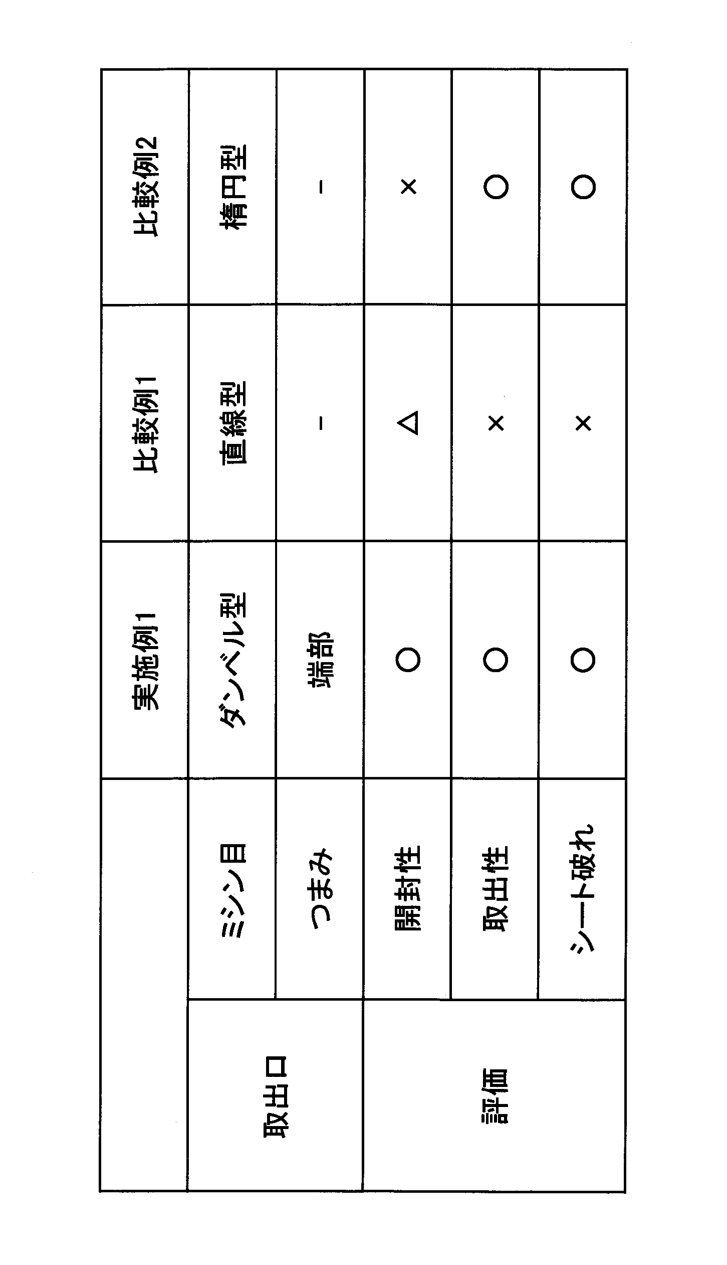
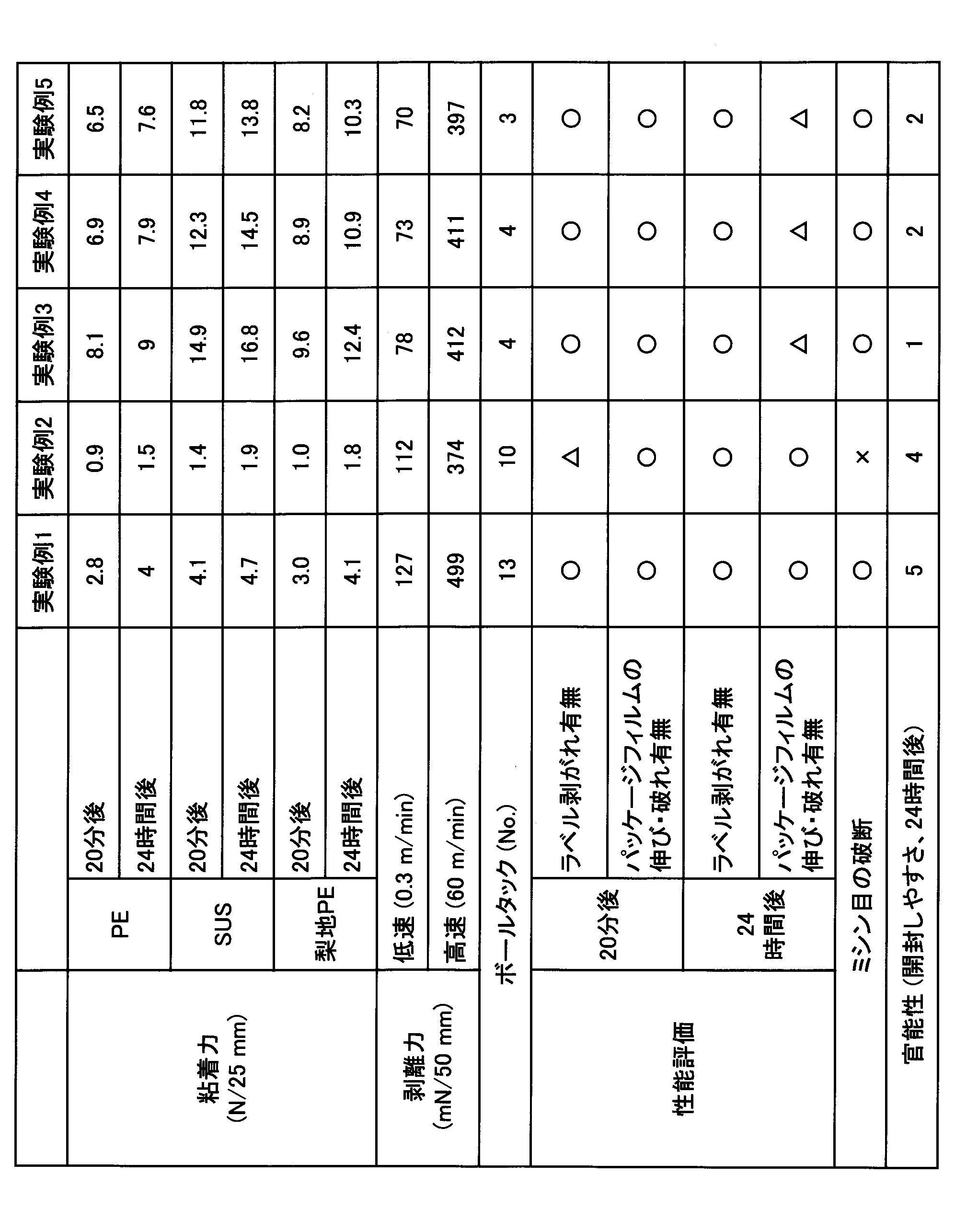
表1より、両端部22、23が第1方向(X方向)の中央24側から両端部22、23側に向かって広くなり、第1方向(X方向)の両端縁E3、E4が領域Rの外側ORに凸となる円弧形状を有するミシン目領域Rの端部23につまみ50が設けられたシート包装体100は、開封性、取出性、シート破れのいずれも良好であった(実施例1)。
一方、取出口20が直線状のスリット(ミシン目M4)は、開封性、取出性、シート破れも不良であった(比較例1)。また略楕円状のスリット(ミシン目M5)で形成されたシート包装体100は、開封性が不良であった(比較例2)。
また、表2より、接着剤としてアクリル系粘着剤(イソシアネート系硬化剤0.3%、エポキシ系架橋剤を含有)を塗布したラベルは、粘着力、剥離力、ボールタック、ラベル剥がれ、パッケージフィルムの伸び・破れ、ミシン目の破断、官能性のいずれも良好であった(実験例1)。
これに対して、接着剤としてアクリル系粘着剤(イソシアネート系硬化剤0.5%、エポキシ系架橋剤を含有)を塗布したラベルは、20分後のラベル剥がれ、ミシン目の破断が不良となった(実験例2)。また、接着剤としてアクリル系粘着剤(イソシアネート系硬化剤2.4%、イソシアネート系架橋剤を含有)、アクリル系粘着剤(イソシアネート系硬化剤3.5%、イソシアネート系架橋剤を含有)及びアクリル系粘着剤(イソシアネート系硬化剤3.9%、イソシアネート系架橋剤を含有)を塗布したラベルは、24時間後のパッケージフィルム破れ、官能性が不良であった(実験例3~5)。
これらの結果から、天面の一部の領域を囲み且つ開裂して取出口を構成するミシン目が包装袋の天面に設けられ、該領域につまみが設けられているシート包装体は、取出口の形成が容易であることが判った。また、このようなつまみが、該領域に接着される接着部と、該領域に接着されない非接着部とを有する、シート包装体は、つまみがつまみ易く、引き上げ易いことが判った。
以上、本発明の実施形態について説明したが、本発明は特定の実施形態に限定されるものではなく、請求の範囲に記載された発明の範囲内において、種々の変形、変更が可能である。
以下、本発明の好ましい態様を付記する。
本発明に係る第1の態様は、積層された複数枚のシートを収容する包装袋と、前記包装袋の天面に開口する取出口とを有し、前記天面には、前記天面の一部の領域を囲み且つ開裂して前記取出口を構成するミシン目が設けられ、前記領域には、つまみが設けられている、シート包装体である。
本明細書において、天面の一部とは、天面の半分より少ない範囲の部分を示す。ミシン目とは、カットとタイ(2つのカット間のカットされていない部分)が交互に配置され、タイが破断すると両隣のカットが連続したカットになる開裂用切目線を示す。また、つまみとは、指先等につままれる部分または部材を示す。
第1の態様では、ミシン目で囲まれた天面の一部の領域(以下、ミシン目領域という場合がある)につまみが設けられていることで、つまみをつまんで引き上げるとミシン目が開裂し、天面のミシン目領域に対応する部分に取出口を開口させることができる。そのため、第1の態様によれば、取出口の形成が容易なシート包装体を提供することができる。
本発明に係る第2の態様は、前記つまみは、前記領域に接着される接着部と、前記領域に接着されない非接着部とを有する、シート包装体である。第2の態様では、つまみがミシン目領域に接着する接着部とミシン目領域に接着しない非接着部を有することで、つまみの接着部がミシン目領域に固定された状態で、つまみの非接着部を指先でつまむことができる。そのため、第2の態様によれば、つまみがつまみ易く、引き上げ易い。
本発明に係る第3の態様は、前記つまみは、前記接着部と前記非接着部との面積比が4:1~8:1である、シート包装体である。ここで、面積比とは、接着部の面積と非接着部の面積との比を示す。第3の態様では、つまみの接着部と非接着部をこのような範囲の面積比にすることで、つまみがミシン目領域に固定された状態を維持しながら、つまみがよりつまみ易く、より引き上げ易くなる。
本発明に係る第4の態様は、前記接着部の一部が、前記領域の外側に接着されている、シート包装体である。ここで、接着部の一部とは、接着部の半分より少ない範囲の部分を示す。第4の態様では、つまみの接着部の一部がミシン目領域の外側に接着する構成が許容されることで、シート包装体の製造時につまみを包装袋に別部材として取り付ける場合に、つまみの取り付け作業が容易になる。
また、第4の態様では、接着部の半分より多い範囲の部分はミシン目領域に固定されているため、つまみをつまんで引き上げた際に、つまみがミシン目領域に固定された状態で、ミシン目が開裂し、ミシン目領域の外側に接着する接着部の一部は剥離する。そのため、第4の態様では、接着部の一部がミシン目領域の外側に接着されていても、取出口を天面に開口させることができる。
本発明に係る第5の態様は、前記接着部の粘着力が、2N/25mm以上6N/25mm以下である、シート包装体である。ここで、粘着力とは、JIS Z0237を参考にした粘着力試験法により測定した引きはがし抵抗値を示す。
第5の態様では、粘着力が2N/25mm以上6N/25mm以下の接着部を有するつまみをミシン目領域に設けることで、つまみをつまんで引き上げた際に、つまみがミシン目領域に固定された状態で、ミシン目を開裂させることができる。これにより、第5の態様では、容易に取出口を開口させることができる。
また、第5の態様では、接着部の一部がミシン目領域の外側に接着されている場合でも、ミシン目領域の内側ではつまみが接着したままミシン目が開裂し、ミシン目領域の外側に接着する接着部の一部を剥離させることができる。これにより、第5の態様では、接着部の一部がミシン目領域の外側に接着されていても、容易に取出口を開口させることができる。
本発明に係る第6の態様は、前記非接着部は、円弧状の自由端を有する、シート包装体である。ここで、自由端とは、非接着部の端縁が固定されていないことを示す。第6の態様では、つまみの非接着部が円弧状の自由端を有することで、つまみがさらにつまみ易く、さらに引き上げ易くなる。
本発明に係る第7の態様は、前記領域が、第1方向に延びる所与の長さと、前記第1方向と交差する第2方向に拡がる所与の幅とを有し、前記領域の前記第1方向の少なくとも一方の端部に、前記つまみが設けられている、シート包装体である。
本明細書において、第1方向とは、包装袋の天面上の所定の一方向に沿う方向を示す。第1方向と交差する第2方向とは、包装袋の天面上の所定の一方向に沿う方向と直交する方向または筋かいに交わる方向に沿う方向を示す。領域の第1方向の端部とは、ミシン目領域の第1方向におけるいずれか一方の端部を示す。
第7の態様では、第1方向に延びる所与の長さと第1方向と交差する第2方向に拡がる所与の幅とを有することで、ミシン目領域の輪郭形状は、第1方向が長手方向で第2方向が幅方向となる細長い形状となる。また、つまみがミシン目領域の第1方向の少なくとも一方の端部に設けられていることで、つまみを第1方向に沿って他方の端部側に引っ張り易い。
また、第7の態様では、つまみが第1方向に沿って他方の端部側に引っ張られると、ミシン目が開裂して、ミシン目領域に対応する細長い形状の取出口を開口させることができる。これにより、シートが詰まりにくく、周囲が破断しにくい取出口を天面に形成することができる。そのため、第7の態様によれば、取出性に優れるシート包装体が得られる。
本発明に係る第8の態様は、前記領域は、前記領域の前記第1方向の両端部側から前記領域の中央側に向かって前記幅が狭くなる、シート包装体である。ここで、領域の第1方向の両端部側から中央側に向かって幅が狭くなるとは、ミシン目領域の第2方向の幅が第1方向の中央側から両端部側に向かって広くなることを示す。
第8の態様では、このようにミシン目領域の幅が第1方向の両端部側から中央側に向かって狭くなることで、ミシン目領域の長手方向の端部に設けられたつまみをつまんで第1方向の中央側に引っ張ったときに、長手方向の端部から中央に向かってミシン目が開裂しやすくなる。これにより、第8の態様では、より取出口の形成が容易になる。
また、第8の態様では、天面に開口する取出口の幅が取出口の中央側より両端部側で広くなる。そのため、シートを引き出す際にシートが詰まりやすく破断し易い取出口の両端部で、シートが詰まりにくくなり、シートの破断を抑制することができる。これにより、第8の態様では、より取出性に優れるシート包装体が得られる。
本発明に係る第9の態様は、前記領域は、前記領域の前記第1方向の両端縁が前記領域の外側に凸となる円弧形状を有する、シート包装体である。ここで、領域の前記第1方向の両端縁とは、ミシン目領域の第1方向に対向する各端縁を示す。凸となる円弧形状を有するとは、各端縁が凸状に湾曲することを示す。
第9の態様では、第1方向の両端縁がミシン目領域の外側に凸となる円弧形状を有することで、つまみをつまんで引き上げたときに、つまみが設けられたミシン目領域の長手方向の端部側の端縁が開裂しやすくなる。また、つまみが設けられていないミシン目領域の長手方向の端部側の端縁も開裂しやすくなる。これにより、第9の態様では、さらに取出口の形成が容易になる。
また、第9の態様では、天面に開口する取出口の長手方向の両端縁を取出口の外側に向かって湾曲させることができる。そのため、シートを引き出す際にシートが詰まりやすく破断し易い取出口の両端部で、シートの擦れが緩和される。これにより、さらにシートが詰まりにくくなり、シートの破断を抑制することができる。そのため、第9の態様では、さらに取出性に優れるシート包装体が得られる。
本出願は、2020年1月31日に出願された日本国特許出願2020-015212号に基づく優先権を主張するものであり、その全内容をここに援用する。
100 シート包装体
S シート(衛生薄葉紙)
SL シート積層体
10 包装袋
11 天面
11A 第1方向の中央
11B 第2方向の中央
12 底面
13 正面
14 背面
15、16 側面
20 取出口
R 領域
IR 内側
OR 外側
M、M1、M2、M3、M4、M5 ミシン目
C、C1、C2 カット
T、T1、T2 タイ
21 基部
22、23 端部
24 中央
30 シール部
40 シール部
50 つまみ
51 接着部
51A 接着層
51B 一部
52 非接着部
52A 自由端
L1、L2 長さ
W1、W2、W3 幅
OP 開口
E1、E2、E3、E4 端縁
B 破断片
S シート(衛生薄葉紙)
SL シート積層体
10 包装袋
11 天面
11A 第1方向の中央
11B 第2方向の中央
12 底面
13 正面
14 背面
15、16 側面
20 取出口
R 領域
IR 内側
OR 外側
M、M1、M2、M3、M4、M5 ミシン目
C、C1、C2 カット
T、T1、T2 タイ
21 基部
22、23 端部
24 中央
30 シール部
40 シール部
50 つまみ
51 接着部
51A 接着層
51B 一部
52 非接着部
52A 自由端
L1、L2 長さ
W1、W2、W3 幅
OP 開口
E1、E2、E3、E4 端縁
B 破断片
Claims (9)
- 積層された複数枚のシートを収容する包装袋と、
前記包装袋の天面に開口する取出口とを有し、
前記天面には、前記天面の一部の領域を囲み且つ開裂して前記取出口を構成するミシン目が設けられ、
前記領域には、つまみが設けられている、シート包装体。 - 前記つまみは、前記領域に接着される接着部と、前記領域に接着されない非接着部とを有する、請求項1に記載のシート包装体。
- 前記つまみは、前記接着部と前記非接着部との面積比が4:1~8:1である、請求項2に記載のシート包装体。
- 前記接着部の一部が、前記領域の外側に接着されている、請求項2または3に記載のシート包装体。
- 前記接着部の粘着力が、2N/25mm以上6N/25mm以下である、請求項2乃至4のいずれか1項に記載のシート包装体。
- 前記非接着部は、円弧状の自由端部を有する、請求項2乃至5のいずれか1項に記載のシート包装体。
- 前記領域が、第1方向に延びる所与の長さと、前記第1方向と交差する第2方向に拡がる所与の幅とを有し、
前記領域の前記第1方向の少なくとも一方の端部に、前記つまみが設けられている、請求項1乃至6のいずれか1項に記載のシート包装体。 - 前記領域は、前記領域の前記第1方向の両端部側から前記領域の中央側に向かって前記幅が狭くなる、請求項7に記載のシート包装体。
- 前記領域は、前記領域の前記第1方向の両端縁が前記領域の外側に凸となる円弧形状を有する、請求項7または8に記載のシート包装体。
Priority Applications (3)
| Application Number | Priority Date | Filing Date | Title |
|---|---|---|---|
| US17/753,796 US20220340345A1 (en) | 2020-01-31 | 2021-01-20 | Sheet package |
| CN202180005277.1A CN114364293A (zh) | 2020-01-31 | 2021-01-20 | 片包装体 |
| EP21747024.4A EP4098581A4 (en) | 2020-01-31 | 2021-01-20 | FOIL PACKAGING |
Applications Claiming Priority (2)
| Application Number | Priority Date | Filing Date | Title |
|---|---|---|---|
| JP2020-015212 | 2020-01-31 | ||
| JP2020015212A JP2021123340A (ja) | 2020-01-31 | 2020-01-31 | シート包装体 |
Publications (1)
| Publication Number | Publication Date |
|---|---|
| WO2021153386A1 true WO2021153386A1 (ja) | 2021-08-05 |
Family
ID=77079846
Family Applications (1)
| Application Number | Title | Priority Date | Filing Date |
|---|---|---|---|
| PCT/JP2021/001911 WO2021153386A1 (ja) | 2020-01-31 | 2021-01-20 | シート包装体 |
Country Status (5)
| Country | Link |
|---|---|
| US (1) | US20220340345A1 (ja) |
| EP (1) | EP4098581A4 (ja) |
| JP (1) | JP2021123340A (ja) |
| CN (1) | CN114364293A (ja) |
| WO (1) | WO2021153386A1 (ja) |
Citations (7)
| Publication number | Priority date | Publication date | Assignee | Title |
|---|---|---|---|---|
| JP2005178844A (ja) * | 2003-12-19 | 2005-07-07 | Pigeon Corp | ウェットティシュ容器 |
| JP2008183034A (ja) | 2007-01-26 | 2008-08-14 | Oji Nepia Kk | 袋入り家庭用薄葉紙 |
| US20110052107A1 (en) * | 2008-04-09 | 2011-03-03 | Bernd Schlarp | Packaging bag |
| JP2014213910A (ja) * | 2013-04-26 | 2014-11-17 | 王子ホールディングス株式会社 | 再封可能な包装袋 |
| JP2018172145A (ja) * | 2017-03-31 | 2018-11-08 | 大王製紙株式会社 | フィルム包装ティシュー |
| JP2018177364A (ja) | 2017-04-10 | 2018-11-15 | ユニバーサル・ペーパー株式会社 | 開封用ミシン目入りフィルム包装体 |
| JP2020015212A (ja) | 2018-07-25 | 2020-01-30 | 三井化学株式会社 | 連結パイプおよび連結パイプの製造方法 |
Family Cites Families (10)
| Publication number | Priority date | Publication date | Assignee | Title |
|---|---|---|---|---|
| EP0763621B1 (en) * | 1995-09-18 | 2002-11-27 | Toray Industries, Inc. | A base fabric for air bags, a process for producing it and an air bag comprising it |
| US20070081745A1 (en) * | 2004-11-11 | 2007-04-12 | Konrad Tetenborg | Perforated form-fill-seal (ffs) bag |
| JP2007112503A (ja) * | 2005-10-24 | 2007-05-10 | Oji Nepia Kk | 衛生用紙収納用カートン |
| US7789291B2 (en) * | 2008-06-10 | 2010-09-07 | Printpack Illinois, Inc. | Packaging article and method with particular tearing slit arrangement |
| JP2013001435A (ja) * | 2011-06-17 | 2013-01-07 | Nitto Lifetech Kk | 袋体構成部材用多孔質フィルム及びカイロ用袋体構成部材 |
| DE102012222719A1 (de) * | 2012-12-11 | 2014-06-12 | Robert Bosch Gmbh | Folienbeutel zum Bevorraten eines Fluids und Vorrichtung zum Bereitstellen eines Fluids |
| JP6576972B2 (ja) * | 2017-03-31 | 2019-09-18 | 大王製紙株式会社 | フィルム包装ティシュー |
| JP7224121B2 (ja) * | 2018-06-29 | 2023-02-17 | 大王製紙株式会社 | 衛生薄葉紙包装体 |
| CN113165793A (zh) * | 2018-11-29 | 2021-07-23 | 大王制纸株式会社 | 片材包装体 |
| JP7317775B2 (ja) * | 2020-08-26 | 2023-07-31 | 大王製紙株式会社 | フィルム包装ティシュー |
-
2020
- 2020-01-31 JP JP2020015212A patent/JP2021123340A/ja active Pending
-
2021
- 2021-01-20 WO PCT/JP2021/001911 patent/WO2021153386A1/ja unknown
- 2021-01-20 EP EP21747024.4A patent/EP4098581A4/en active Pending
- 2021-01-20 US US17/753,796 patent/US20220340345A1/en not_active Abandoned
- 2021-01-20 CN CN202180005277.1A patent/CN114364293A/zh active Pending
Patent Citations (7)
| Publication number | Priority date | Publication date | Assignee | Title |
|---|---|---|---|---|
| JP2005178844A (ja) * | 2003-12-19 | 2005-07-07 | Pigeon Corp | ウェットティシュ容器 |
| JP2008183034A (ja) | 2007-01-26 | 2008-08-14 | Oji Nepia Kk | 袋入り家庭用薄葉紙 |
| US20110052107A1 (en) * | 2008-04-09 | 2011-03-03 | Bernd Schlarp | Packaging bag |
| JP2014213910A (ja) * | 2013-04-26 | 2014-11-17 | 王子ホールディングス株式会社 | 再封可能な包装袋 |
| JP2018172145A (ja) * | 2017-03-31 | 2018-11-08 | 大王製紙株式会社 | フィルム包装ティシュー |
| JP2018177364A (ja) | 2017-04-10 | 2018-11-15 | ユニバーサル・ペーパー株式会社 | 開封用ミシン目入りフィルム包装体 |
| JP2020015212A (ja) | 2018-07-25 | 2020-01-30 | 三井化学株式会社 | 連結パイプおよび連結パイプの製造方法 |
Non-Patent Citations (1)
| Title |
|---|
| See also references of EP4098581A4 |
Also Published As
| Publication number | Publication date |
|---|---|
| EP4098581A4 (en) | 2024-02-14 |
| CN114364293A (zh) | 2022-04-15 |
| US20220340345A1 (en) | 2022-10-27 |
| JP2021123340A (ja) | 2021-08-30 |
| EP4098581A1 (en) | 2022-12-07 |
Similar Documents
| Publication | Publication Date | Title |
|---|---|---|
| JP3665374B2 (ja) | 一時的結合のための粘着フイルムのストリツプの使用 | |
| EP1873082B1 (en) | Process for making packages for hygiene articles | |
| JP5198090B2 (ja) | 衛生用シートロール包装体 | |
| JP2019532880A (ja) | 開封及び再閉鎖性が改善された吸収性物品パッケージ | |
| WO2021153386A1 (ja) | シート包装体 | |
| JP2022187929A (ja) | 積層体及び包装袋 | |
| JP7471856B2 (ja) | シート包装体 | |
| JP2009007031A (ja) | ロールペーパー包装体 | |
| JP2021054510A (ja) | 包装体 | |
| JP7211811B2 (ja) | 包装袋 | |
| JP7153219B2 (ja) | 袋 | |
| JP5970792B2 (ja) | 紙容器 | |
| JP2022138345A (ja) | シート包装体 | |
| JP2010030691A (ja) | 包装材およびその製造方法 | |
| JP7456879B2 (ja) | シート包装体 | |
| WO2021200391A1 (ja) | シート包装体 | |
| JP2022138344A (ja) | シート包装体 | |
| JP6579761B2 (ja) | 包材および包装体 | |
| JP6914797B2 (ja) | 包装体 | |
| WO2023166989A1 (ja) | 包装袋、及びシート包装体 | |
| JP7427476B2 (ja) | シート包装体、及びシート包装体の製造方法 | |
| WO2023188869A1 (ja) | 衛生薄葉紙包装体、及び衛生薄葉紙包装体の製造方法 | |
| JP2006219165A (ja) | 包装袋 | |
| JP7049161B2 (ja) | 包装袋、包装袋の使用方法、および包装袋の製造方法 | |
| WO2023053526A1 (ja) | 包装袋、及びシート包装体 |
Legal Events
| Date | Code | Title | Description |
|---|---|---|---|
| 121 | Ep: the epo has been informed by wipo that ep was designated in this application |
Ref document number: 21747024 Country of ref document: EP Kind code of ref document: A1 |
|
| NENP | Non-entry into the national phase |
Ref country code: DE |
|
| ENP | Entry into the national phase |
Ref document number: 2021747024 Country of ref document: EP Effective date: 20220831 |