WO2021153292A1 - 非水電解質二次電池及び二次電池モジュール - Google Patents
非水電解質二次電池及び二次電池モジュール Download PDFInfo
- Publication number
- WO2021153292A1 WO2021153292A1 PCT/JP2021/001388 JP2021001388W WO2021153292A1 WO 2021153292 A1 WO2021153292 A1 WO 2021153292A1 JP 2021001388 W JP2021001388 W JP 2021001388W WO 2021153292 A1 WO2021153292 A1 WO 2021153292A1
- Authority
- WO
- WIPO (PCT)
- Prior art keywords
- positive electrode
- secondary battery
- aqueous electrolyte
- electrolyte secondary
- elastic body
- Prior art date
Links
- 239000011255 nonaqueous electrolyte Substances 0.000 title claims abstract description 83
- 239000007774 positive electrode material Substances 0.000 claims abstract description 44
- RSNHXDVSISOZOB-UHFFFAOYSA-N lithium nickel Chemical compound [Li].[Ni] RSNHXDVSISOZOB-UHFFFAOYSA-N 0.000 claims abstract description 28
- 229910052751 metal Inorganic materials 0.000 claims abstract description 19
- PXHVJJICTQNCMI-UHFFFAOYSA-N Nickel Chemical compound [Ni] PXHVJJICTQNCMI-UHFFFAOYSA-N 0.000 claims abstract description 16
- 239000002131 composite material Substances 0.000 claims description 30
- 239000007773 negative electrode material Substances 0.000 claims description 30
- 239000010936 titanium Substances 0.000 abstract description 23
- 229910052744 lithium Inorganic materials 0.000 abstract description 4
- 230000006835 compression Effects 0.000 abstract description 3
- 238000007906 compression Methods 0.000 abstract description 3
- 229910052759 nickel Inorganic materials 0.000 abstract description 3
- WHXSMMKQMYFTQS-UHFFFAOYSA-N Lithium Chemical compound [Li] WHXSMMKQMYFTQS-UHFFFAOYSA-N 0.000 abstract description 2
- 229910052719 titanium Inorganic materials 0.000 abstract description 2
- RTAQQCXQSZGOHL-UHFFFAOYSA-N Titanium Chemical compound [Ti] RTAQQCXQSZGOHL-UHFFFAOYSA-N 0.000 abstract 1
- 239000000470 constituent Substances 0.000 abstract 1
- 239000010410 layer Substances 0.000 description 48
- 230000020169 heat generation Effects 0.000 description 13
- 125000006850 spacer group Chemical group 0.000 description 13
- 239000000463 material Substances 0.000 description 11
- 238000004804 winding Methods 0.000 description 11
- 239000008151 electrolyte solution Substances 0.000 description 9
- 239000000203 mixture Substances 0.000 description 8
- OKTJSMMVPCPJKN-UHFFFAOYSA-N Carbon Chemical group [C] OKTJSMMVPCPJKN-UHFFFAOYSA-N 0.000 description 7
- 239000011230 binding agent Substances 0.000 description 7
- 238000001816 cooling Methods 0.000 description 7
- 239000010408 film Substances 0.000 description 7
- 239000011888 foil Substances 0.000 description 7
- -1 polypropylene Polymers 0.000 description 7
- 239000002002 slurry Substances 0.000 description 7
- JOYRKODLDBILNP-UHFFFAOYSA-N Ethyl urethane Chemical compound CCOC(N)=O JOYRKODLDBILNP-UHFFFAOYSA-N 0.000 description 6
- 229910052782 aluminium Inorganic materials 0.000 description 6
- 238000006073 displacement reaction Methods 0.000 description 6
- 239000006260 foam Substances 0.000 description 6
- 239000002184 metal Substances 0.000 description 6
- 229920005989 resin Polymers 0.000 description 6
- 239000011347 resin Substances 0.000 description 6
- 238000007789 sealing Methods 0.000 description 6
- 229910052799 carbon Inorganic materials 0.000 description 5
- 229910052710 silicon Inorganic materials 0.000 description 5
- HBBGRARXTFLTSG-UHFFFAOYSA-N Lithium ion Chemical compound [Li+] HBBGRARXTFLTSG-UHFFFAOYSA-N 0.000 description 4
- SECXISVLQFMRJM-UHFFFAOYSA-N N-Methylpyrrolidone Chemical compound CN1CCCC1=O SECXISVLQFMRJM-UHFFFAOYSA-N 0.000 description 4
- 239000003575 carbonaceous material Substances 0.000 description 4
- 239000011248 coating agent Substances 0.000 description 4
- 238000000576 coating method Methods 0.000 description 4
- 238000007599 discharging Methods 0.000 description 4
- 229910001416 lithium ion Inorganic materials 0.000 description 4
- 229910052718 tin Inorganic materials 0.000 description 4
- 239000002033 PVDF binder Substances 0.000 description 3
- 239000004743 Polypropylene Substances 0.000 description 3
- 239000000956 alloy Substances 0.000 description 3
- 229910045601 alloy Inorganic materials 0.000 description 3
- XAGFODPZIPBFFR-UHFFFAOYSA-N aluminium Chemical compound [Al] XAGFODPZIPBFFR-UHFFFAOYSA-N 0.000 description 3
- 239000004020 conductor Substances 0.000 description 3
- 238000011156 evaluation Methods 0.000 description 3
- 229910052748 manganese Inorganic materials 0.000 description 3
- 229920005672 polyolefin resin Polymers 0.000 description 3
- 229920001155 polypropylene Polymers 0.000 description 3
- 229920002981 polyvinylidene fluoride Polymers 0.000 description 3
- 238000002360 preparation method Methods 0.000 description 3
- 150000003839 salts Chemical class 0.000 description 3
- RYGMFSIKBFXOCR-UHFFFAOYSA-N Copper Chemical compound [Cu] RYGMFSIKBFXOCR-UHFFFAOYSA-N 0.000 description 2
- KMTRUDSVKNLOMY-UHFFFAOYSA-N Ethylene carbonate Chemical compound O=C1OCCO1 KMTRUDSVKNLOMY-UHFFFAOYSA-N 0.000 description 2
- 229910013716 LiNi Inorganic materials 0.000 description 2
- 229910013870 LiPF 6 Inorganic materials 0.000 description 2
- 229920003171 Poly (ethylene oxide) Polymers 0.000 description 2
- 239000004698 Polyethylene Substances 0.000 description 2
- 239000006230 acetylene black Substances 0.000 description 2
- 239000011149 active material Substances 0.000 description 2
- 239000003125 aqueous solvent Substances 0.000 description 2
- 229920002678 cellulose Polymers 0.000 description 2
- 239000001913 cellulose Substances 0.000 description 2
- 229910052802 copper Inorganic materials 0.000 description 2
- 239000010949 copper Substances 0.000 description 2
- 239000002612 dispersion medium Substances 0.000 description 2
- 239000003792 electrolyte Substances 0.000 description 2
- 230000002708 enhancing effect Effects 0.000 description 2
- 229910002804 graphite Inorganic materials 0.000 description 2
- 239000010439 graphite Substances 0.000 description 2
- 229910052739 hydrogen Inorganic materials 0.000 description 2
- 238000009413 insulation Methods 0.000 description 2
- 229910052742 iron Inorganic materials 0.000 description 2
- 238000002844 melting Methods 0.000 description 2
- 230000008018 melting Effects 0.000 description 2
- 238000000034 method Methods 0.000 description 2
- 239000012046 mixed solvent Substances 0.000 description 2
- 229910052757 nitrogen Inorganic materials 0.000 description 2
- 229910052760 oxygen Inorganic materials 0.000 description 2
- 230000000704 physical effect Effects 0.000 description 2
- 229920002239 polyacrylonitrile Polymers 0.000 description 2
- 229920000573 polyethylene Polymers 0.000 description 2
- 229920001343 polytetrafluoroethylene Polymers 0.000 description 2
- 239000004810 polytetrafluoroethylene Substances 0.000 description 2
- 239000011148 porous material Substances 0.000 description 2
- 230000000452 restraining effect Effects 0.000 description 2
- 239000007787 solid Substances 0.000 description 2
- XLYOFNOQVPJJNP-UHFFFAOYSA-N water Substances O XLYOFNOQVPJJNP-UHFFFAOYSA-N 0.000 description 2
- 229920000178 Acrylic resin Polymers 0.000 description 1
- 239000004925 Acrylic resin Substances 0.000 description 1
- 238000012935 Averaging Methods 0.000 description 1
- 229920002134 Carboxymethyl cellulose Polymers 0.000 description 1
- 229920003043 Cellulose fiber Polymers 0.000 description 1
- 244000043261 Hevea brasiliensis Species 0.000 description 1
- 229910011337 LiNi0.70Co0.15Mn0.15O2 Inorganic materials 0.000 description 1
- 239000004952 Polyamide Substances 0.000 description 1
- 239000004793 Polystyrene Substances 0.000 description 1
- XUIMIQQOPSSXEZ-UHFFFAOYSA-N Silicon Chemical compound [Si] XUIMIQQOPSSXEZ-UHFFFAOYSA-N 0.000 description 1
- ATJFFYVFTNAWJD-UHFFFAOYSA-N Tin Chemical compound [Sn] ATJFFYVFTNAWJD-UHFFFAOYSA-N 0.000 description 1
- 229920006311 Urethane elastomer Polymers 0.000 description 1
- 150000001336 alkenes Chemical class 0.000 description 1
- 150000001408 amides Chemical class 0.000 description 1
- 229910003481 amorphous carbon Inorganic materials 0.000 description 1
- 239000004760 aramid Substances 0.000 description 1
- 229920003235 aromatic polyamide Polymers 0.000 description 1
- 229910021383 artificial graphite Inorganic materials 0.000 description 1
- 229910052796 boron Inorganic materials 0.000 description 1
- 238000005219 brazing Methods 0.000 description 1
- QHIWVLPBUQWDMQ-UHFFFAOYSA-N butyl prop-2-enoate;methyl 2-methylprop-2-enoate;prop-2-enoic acid Chemical compound OC(=O)C=C.COC(=O)C(C)=C.CCCCOC(=O)C=C QHIWVLPBUQWDMQ-UHFFFAOYSA-N 0.000 description 1
- 150000001721 carbon Chemical class 0.000 description 1
- 239000000919 ceramic Substances 0.000 description 1
- 229910052804 chromium Inorganic materials 0.000 description 1
- 150000001875 compounds Chemical class 0.000 description 1
- 230000008602 contraction Effects 0.000 description 1
- 239000011889 copper foil Substances 0.000 description 1
- 238000005260 corrosion Methods 0.000 description 1
- 230000007797 corrosion Effects 0.000 description 1
- IEJIGPNLZYLLBP-UHFFFAOYSA-N dimethyl carbonate Chemical compound COC(=O)OC IEJIGPNLZYLLBP-UHFFFAOYSA-N 0.000 description 1
- 239000006185 dispersion Substances 0.000 description 1
- 230000000694 effects Effects 0.000 description 1
- 229920001971 elastomer Polymers 0.000 description 1
- 239000000806 elastomer Substances 0.000 description 1
- 239000007772 electrode material Substances 0.000 description 1
- 238000005516 engineering process Methods 0.000 description 1
- 150000002148 esters Chemical class 0.000 description 1
- 150000002170 ethers Chemical class 0.000 description 1
- JBTWLSYIZRCDFO-UHFFFAOYSA-N ethyl methyl carbonate Chemical compound CCOC(=O)OC JBTWLSYIZRCDFO-UHFFFAOYSA-N 0.000 description 1
- 230000001747 exhibiting effect Effects 0.000 description 1
- 239000000835 fiber Substances 0.000 description 1
- 229920001973 fluoroelastomer Polymers 0.000 description 1
- 238000010438 heat treatment Methods 0.000 description 1
- 229910052738 indium Inorganic materials 0.000 description 1
- 239000011810 insulating material Substances 0.000 description 1
- 230000010220 ion permeability Effects 0.000 description 1
- 239000003273 ketjen black Substances 0.000 description 1
- 229910003002 lithium salt Inorganic materials 0.000 description 1
- 159000000002 lithium salts Chemical class 0.000 description 1
- 229910052749 magnesium Inorganic materials 0.000 description 1
- 230000014759 maintenance of location Effects 0.000 description 1
- 238000004519 manufacturing process Methods 0.000 description 1
- 229920003052 natural elastomer Polymers 0.000 description 1
- 229910021382 natural graphite Inorganic materials 0.000 description 1
- 229920001194 natural rubber Polymers 0.000 description 1
- 229910052758 niobium Inorganic materials 0.000 description 1
- 150000002825 nitriles Chemical class 0.000 description 1
- 239000004745 nonwoven fabric Substances 0.000 description 1
- JRZJOMJEPLMPRA-UHFFFAOYSA-N olefin Natural products CCCCCCCC=C JRZJOMJEPLMPRA-UHFFFAOYSA-N 0.000 description 1
- 239000003960 organic solvent Substances 0.000 description 1
- 239000002245 particle Substances 0.000 description 1
- 230000000149 penetrating effect Effects 0.000 description 1
- 229920002647 polyamide Polymers 0.000 description 1
- 229920001707 polybutylene terephthalate Polymers 0.000 description 1
- 229920000515 polycarbonate Polymers 0.000 description 1
- 239000004417 polycarbonate Substances 0.000 description 1
- 229920006149 polyester-amide block copolymer Polymers 0.000 description 1
- 229920001721 polyimide Polymers 0.000 description 1
- 239000009719 polyimide resin Substances 0.000 description 1
- 229920002223 polystyrene Polymers 0.000 description 1
- 229920002635 polyurethane Polymers 0.000 description 1
- 239000004814 polyurethane Substances 0.000 description 1
- 238000005096 rolling process Methods 0.000 description 1
- 238000007790 scraping Methods 0.000 description 1
- 238000000926 separation method Methods 0.000 description 1
- 229910002028 silica xerogel Inorganic materials 0.000 description 1
- 239000010703 silicon Substances 0.000 description 1
- 229920002379 silicone rubber Polymers 0.000 description 1
- 239000004945 silicone rubber Substances 0.000 description 1
- 238000003756 stirring Methods 0.000 description 1
- 239000002344 surface layer Substances 0.000 description 1
- 229910052715 tantalum Inorganic materials 0.000 description 1
- 229920002725 thermoplastic elastomer Polymers 0.000 description 1
- 229920005992 thermoplastic resin Polymers 0.000 description 1
- 229920001187 thermosetting polymer Polymers 0.000 description 1
- 239000010409 thin film Substances 0.000 description 1
- 229910052721 tungsten Inorganic materials 0.000 description 1
- 229910052720 vanadium Inorganic materials 0.000 description 1
- 238000003466 welding Methods 0.000 description 1
- 239000002759 woven fabric Substances 0.000 description 1
- 229910052725 zinc Inorganic materials 0.000 description 1
- 229910052726 zirconium Inorganic materials 0.000 description 1
Images


Classifications
-
- H—ELECTRICITY
- H01—ELECTRIC ELEMENTS
- H01M—PROCESSES OR MEANS, e.g. BATTERIES, FOR THE DIRECT CONVERSION OF CHEMICAL ENERGY INTO ELECTRICAL ENERGY
- H01M4/00—Electrodes
- H01M4/02—Electrodes composed of, or comprising, active material
- H01M4/36—Selection of substances as active materials, active masses, active liquids
- H01M4/48—Selection of substances as active materials, active masses, active liquids of inorganic oxides or hydroxides
- H01M4/52—Selection of substances as active materials, active masses, active liquids of inorganic oxides or hydroxides of nickel, cobalt or iron
- H01M4/525—Selection of substances as active materials, active masses, active liquids of inorganic oxides or hydroxides of nickel, cobalt or iron of mixed oxides or hydroxides containing iron, cobalt or nickel for inserting or intercalating light metals, e.g. LiNiO2, LiCoO2 or LiCoOxFy
-
- H—ELECTRICITY
- H01—ELECTRIC ELEMENTS
- H01M—PROCESSES OR MEANS, e.g. BATTERIES, FOR THE DIRECT CONVERSION OF CHEMICAL ENERGY INTO ELECTRICAL ENERGY
- H01M10/00—Secondary cells; Manufacture thereof
- H01M10/05—Accumulators with non-aqueous electrolyte
- H01M10/052—Li-accumulators
-
- H—ELECTRICITY
- H01—ELECTRIC ELEMENTS
- H01M—PROCESSES OR MEANS, e.g. BATTERIES, FOR THE DIRECT CONVERSION OF CHEMICAL ENERGY INTO ELECTRICAL ENERGY
- H01M10/00—Secondary cells; Manufacture thereof
- H01M10/05—Accumulators with non-aqueous electrolyte
- H01M10/052—Li-accumulators
- H01M10/0525—Rocking-chair batteries, i.e. batteries with lithium insertion or intercalation in both electrodes; Lithium-ion batteries
-
- H—ELECTRICITY
- H01—ELECTRIC ELEMENTS
- H01M—PROCESSES OR MEANS, e.g. BATTERIES, FOR THE DIRECT CONVERSION OF CHEMICAL ENERGY INTO ELECTRICAL ENERGY
- H01M4/00—Electrodes
- H01M4/02—Electrodes composed of, or comprising, active material
- H01M4/04—Processes of manufacture in general
- H01M4/0402—Methods of deposition of the material
- H01M4/0404—Methods of deposition of the material by coating on electrode collectors
-
- H—ELECTRICITY
- H01—ELECTRIC ELEMENTS
- H01M—PROCESSES OR MEANS, e.g. BATTERIES, FOR THE DIRECT CONVERSION OF CHEMICAL ENERGY INTO ELECTRICAL ENERGY
- H01M4/00—Electrodes
- H01M4/02—Electrodes composed of, or comprising, active material
- H01M4/64—Carriers or collectors
- H01M4/66—Selection of materials
- H01M4/661—Metal or alloys, e.g. alloy coatings
-
- H—ELECTRICITY
- H01—ELECTRIC ELEMENTS
- H01M—PROCESSES OR MEANS, e.g. BATTERIES, FOR THE DIRECT CONVERSION OF CHEMICAL ENERGY INTO ELECTRICAL ENERGY
- H01M50/00—Constructional details or processes of manufacture of the non-active parts of electrochemical cells other than fuel cells, e.g. hybrid cells
- H01M50/20—Mountings; Secondary casings or frames; Racks, modules or packs; Suspension devices; Shock absorbers; Transport or carrying devices; Holders
- H01M50/204—Racks, modules or packs for multiple batteries or multiple cells
- H01M50/207—Racks, modules or packs for multiple batteries or multiple cells characterised by their shape
- H01M50/209—Racks, modules or packs for multiple batteries or multiple cells characterised by their shape adapted for prismatic or rectangular cells
-
- H—ELECTRICITY
- H01—ELECTRIC ELEMENTS
- H01M—PROCESSES OR MEANS, e.g. BATTERIES, FOR THE DIRECT CONVERSION OF CHEMICAL ENERGY INTO ELECTRICAL ENERGY
- H01M50/00—Constructional details or processes of manufacture of the non-active parts of electrochemical cells other than fuel cells, e.g. hybrid cells
- H01M50/40—Separators; Membranes; Diaphragms; Spacing elements inside cells
- H01M50/409—Separators, membranes or diaphragms characterised by the material
-
- H—ELECTRICITY
- H01—ELECTRIC ELEMENTS
- H01M—PROCESSES OR MEANS, e.g. BATTERIES, FOR THE DIRECT CONVERSION OF CHEMICAL ENERGY INTO ELECTRICAL ENERGY
- H01M50/00—Constructional details or processes of manufacture of the non-active parts of electrochemical cells other than fuel cells, e.g. hybrid cells
- H01M50/40—Separators; Membranes; Diaphragms; Spacing elements inside cells
- H01M50/46—Separators, membranes or diaphragms characterised by their combination with electrodes
-
- H—ELECTRICITY
- H01—ELECTRIC ELEMENTS
- H01M—PROCESSES OR MEANS, e.g. BATTERIES, FOR THE DIRECT CONVERSION OF CHEMICAL ENERGY INTO ELECTRICAL ENERGY
- H01M50/00—Constructional details or processes of manufacture of the non-active parts of electrochemical cells other than fuel cells, e.g. hybrid cells
- H01M50/40—Separators; Membranes; Diaphragms; Spacing elements inside cells
- H01M50/471—Spacing elements inside cells other than separators, membranes or diaphragms; Manufacturing processes thereof
- H01M50/474—Spacing elements inside cells other than separators, membranes or diaphragms; Manufacturing processes thereof characterised by their position inside the cells
-
- H—ELECTRICITY
- H01—ELECTRIC ELEMENTS
- H01M—PROCESSES OR MEANS, e.g. BATTERIES, FOR THE DIRECT CONVERSION OF CHEMICAL ENERGY INTO ELECTRICAL ENERGY
- H01M50/00—Constructional details or processes of manufacture of the non-active parts of electrochemical cells other than fuel cells, e.g. hybrid cells
- H01M50/40—Separators; Membranes; Diaphragms; Spacing elements inside cells
- H01M50/471—Spacing elements inside cells other than separators, membranes or diaphragms; Manufacturing processes thereof
- H01M50/48—Spacing elements inside cells other than separators, membranes or diaphragms; Manufacturing processes thereof characterised by the material
- H01M50/486—Organic material
-
- H—ELECTRICITY
- H01—ELECTRIC ELEMENTS
- H01M—PROCESSES OR MEANS, e.g. BATTERIES, FOR THE DIRECT CONVERSION OF CHEMICAL ENERGY INTO ELECTRICAL ENERGY
- H01M50/00—Constructional details or processes of manufacture of the non-active parts of electrochemical cells other than fuel cells, e.g. hybrid cells
- H01M50/40—Separators; Membranes; Diaphragms; Spacing elements inside cells
- H01M50/489—Separators, membranes, diaphragms or spacing elements inside the cells, characterised by their physical properties, e.g. swelling degree, hydrophilicity or shut down properties
-
- H—ELECTRICITY
- H01—ELECTRIC ELEMENTS
- H01M—PROCESSES OR MEANS, e.g. BATTERIES, FOR THE DIRECT CONVERSION OF CHEMICAL ENERGY INTO ELECTRICAL ENERGY
- H01M4/00—Electrodes
- H01M4/02—Electrodes composed of, or comprising, active material
- H01M2004/026—Electrodes composed of, or comprising, active material characterised by the polarity
- H01M2004/028—Positive electrodes
-
- H—ELECTRICITY
- H01—ELECTRIC ELEMENTS
- H01M—PROCESSES OR MEANS, e.g. BATTERIES, FOR THE DIRECT CONVERSION OF CHEMICAL ENERGY INTO ELECTRICAL ENERGY
- H01M4/00—Electrodes
- H01M4/02—Electrodes composed of, or comprising, active material
- H01M4/13—Electrodes for accumulators with non-aqueous electrolyte, e.g. for lithium-accumulators; Processes of manufacture thereof
- H01M4/131—Electrodes based on mixed oxides or hydroxides, or on mixtures of oxides or hydroxides, e.g. LiCoOx
-
- H—ELECTRICITY
- H01—ELECTRIC ELEMENTS
- H01M—PROCESSES OR MEANS, e.g. BATTERIES, FOR THE DIRECT CONVERSION OF CHEMICAL ENERGY INTO ELECTRICAL ENERGY
- H01M4/00—Electrodes
- H01M4/02—Electrodes composed of, or comprising, active material
- H01M4/64—Carriers or collectors
- H01M4/66—Selection of materials
-
- Y—GENERAL TAGGING OF NEW TECHNOLOGICAL DEVELOPMENTS; GENERAL TAGGING OF CROSS-SECTIONAL TECHNOLOGIES SPANNING OVER SEVERAL SECTIONS OF THE IPC; TECHNICAL SUBJECTS COVERED BY FORMER USPC CROSS-REFERENCE ART COLLECTIONS [XRACs] AND DIGESTS
- Y02—TECHNOLOGIES OR APPLICATIONS FOR MITIGATION OR ADAPTATION AGAINST CLIMATE CHANGE
- Y02E—REDUCTION OF GREENHOUSE GAS [GHG] EMISSIONS, RELATED TO ENERGY GENERATION, TRANSMISSION OR DISTRIBUTION
- Y02E60/00—Enabling technologies; Technologies with a potential or indirect contribution to GHG emissions mitigation
- Y02E60/10—Energy storage using batteries
-
- Y—GENERAL TAGGING OF NEW TECHNOLOGICAL DEVELOPMENTS; GENERAL TAGGING OF CROSS-SECTIONAL TECHNOLOGIES SPANNING OVER SEVERAL SECTIONS OF THE IPC; TECHNICAL SUBJECTS COVERED BY FORMER USPC CROSS-REFERENCE ART COLLECTIONS [XRACs] AND DIGESTS
- Y02—TECHNOLOGIES OR APPLICATIONS FOR MITIGATION OR ADAPTATION AGAINST CLIMATE CHANGE
- Y02P—CLIMATE CHANGE MITIGATION TECHNOLOGIES IN THE PRODUCTION OR PROCESSING OF GOODS
- Y02P70/00—Climate change mitigation technologies in the production process for final industrial or consumer products
- Y02P70/50—Manufacturing or production processes characterised by the final manufactured product
Definitions
- This disclosure relates to the technology of a non-aqueous electrolyte secondary battery and a secondary battery module.
- the nail piercing test is, for example, a test in which a nail is pierced into a battery to generate an internal short circuit in a simulated manner, the degree of heat generation is examined, and the safety of the battery is confirmed.
- Patent Document 1 describes a non-aqueous electrolytic solution secondary battery having a positive electrode that reversibly occludes lithium ions, wherein the positive electrode is a sheet-shaped current collector that supports an active material layer and the active material layer.
- the current collector contains aluminum and at least one element other than aluminum, and is obtained by averaging the proportions of the elements constituting the current collector in the thickness direction of the current collector.
- a non-aqueous electrolytic solution secondary battery whose average composition is equal to that of an alloy having a liquidus temperature of 630 ° C. or lower is disclosed.
- the melting point of the positive electrode current collector is suppressed to a low level, and the time until the positive electrode current collector is melted during the nail piercing test is shortened, so that the heat generation of the battery in the nail piercing test is suppressed. ..
- Patent Document 2 discloses a positive electrode current collector containing Ti as a current collector exhibiting excellent corrosion resistance.
- Lithium-nickel-containing composite oxides in which the ratio of Ni to the total amount of metal elements excluding Li is 70 mol% to 100 mol% are expected as positive electrode active materials capable of increasing the capacity of batteries. There is a problem that the heat generation temperature of the battery in the piercing test becomes high.
- the secondary battery module is arranged together with at least one non-aqueous electrolyte secondary battery and the non-aqueous electrolyte secondary battery, and receives a load from the non-aqueous electrolyte secondary battery in the arrangement direction.
- a secondary battery module having an elastic body wherein the non-aqueous electrolyte secondary battery includes an electrode body in which a positive electrode, a negative electrode, and a separator arranged between the positive electrode and the negative electrode are laminated, and the electrode.
- a housing for accommodating a body is provided, and the compressive elasticity of the elastic body is 5 MPa to 120 MPa.
- the positive electrode contains a Ti as a main component, and has a positive electrode current collector having a thickness of 1 ⁇ m to 8 ⁇ m and the positive electrode.
- the electrode active material layer is arranged on the current collector and contains a lithium nickel-containing composite oxide in which the ratio of Ni to the total amount of metal elements excluding Li is 70 mol% to 100 mol%.
- the non-aqueous electrolyte secondary battery includes an electrode body in which a positive electrode, a negative electrode, and a separator arranged between the positive electrode and the negative electrode are laminated, and the electrode body to the electrode body.
- a non-aqueous electrolyte secondary battery comprising an elastic body that receives a load in the stacking direction, the electrode body, and a housing that accommodates the elastic body, and the compressive elasticity of the elastic body is 5 MPa to 120 MPa.
- the positive electrode contains Ti as a main component and has a thickness of 1 ⁇ m to 8 ⁇ m and is arranged on the positive electrode current collector, and the ratio of Ni to the total amount of metal elements excluding Li is 70 mol% to 100.
- a positive electrode active material layer containing a molar% lithium nickel-containing composite oxide is provided.
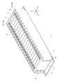
- FIG. 1 is a perspective view of the secondary battery module according to the embodiment.
- FIG. 2 is an exploded perspective view of the secondary battery module according to the embodiment.
- FIG. 3 is a cross-sectional view schematically showing how the non-aqueous electrolyte secondary battery expands.
- FIG. 4 is a schematic cross-sectional view showing the state of the electrode body at the time of the nail piercing test.
- FIG. 5 is a schematic cross-sectional view showing a state in which the elastic body is arranged in the housing.
- FIG. 6 is a schematic perspective view of a cylindrically wound electrode body.
- FIG. 7 is a schematic perspective view showing an example of an elastic body.
- FIG. 8 is a partial schematic cross-sectional view of an elastic body sandwiched between the electrode body and the housing.
- FIG. 1 is a perspective view of the secondary battery module according to the embodiment.
- FIG. 2 is an exploded perspective view of the secondary battery module according to the embodiment.
- the secondary battery module 1 includes a laminate 2, a pair of restraint members 6, and a cooling plate 8.
- the laminate 2 has a plurality of non-aqueous electrolyte secondary batteries 10, a plurality of insulating spacers 12, a plurality of elastic bodies 40, and a pair of end plates 4.
- Each non-aqueous electrolyte secondary battery 10 is a rechargeable secondary battery such as a lithium ion secondary battery.
- the non-aqueous electrolyte secondary battery 10 of the present embodiment is a so-called square battery, and includes an electrode body 38 (see FIG. 3), an electrolytic solution, and a flat rectangular parallelepiped housing 13.
- the housing 13 is composed of an outer can 14 and a sealing plate 16.
- the outer can 14 has a substantially rectangular opening on one surface, and the electrode body 38, the electrolytic solution, and the like are housed in the outer can 14 through the opening. It is desirable that the outer can 14 is covered with an insulating film such as a shrink tube.
- the opening of the outer can 14 is provided with a sealing plate 16 that closes the opening and seals the outer can 14.
- the sealing plate 16 constitutes the first surface 13a of the housing 13.
- the sealing plate 16 and the outer can 14 are joined by, for example, laser, friction stir welding, brazing, or the like.
- the housing 13 may be, for example, a cylindrical case, or may be an exterior body made of a laminated sheet containing a metal layer and a resin layer.
- the electrode body 38 has a structure in which a plurality of sheet-shaped positive electrodes 38a and a plurality of sheet-shaped negative electrodes 38b are alternately laminated via a separator 38d (see FIG. 3).
- the positive electrode 38a, the negative electrode 38b, and the separator 38d are laminated along the first direction X. That is, the first direction X is the stacking direction of the electrode body 38.
- the electrodes located at both ends in this stacking direction face the long side surfaces of the housing 13, which will be described later.
- the first direction X, the second direction Y, and the third direction Z shown in the figure are directions orthogonal to each other.
- the electrode body 38 is a cylindrical winding type electrode body in which a band-shaped positive electrode and a band-shaped negative electrode are laminated via a separator, and a flat winding type electrode body in which a cylindrical winding type electrode body is formed into a flat shape. It may be a type electrode body. In the case of a flat winding type electrode body, a rectangular parallelepiped outer can can be applied, but in the case of a cylindrical winding type electrode body, a cylindrical outer can is applied.
- the sealing plate 16 that is, the first surface 13a of the housing 13, is provided with an output terminal 18 electrically connected to the positive electrode 38a of the electrode body 38 from one end in the longitudinal direction, and the electrode body 38 is provided from the other end.
- An output terminal 18 electrically connected to the negative electrode 38b is provided.
- the output terminal 18 connected to the positive electrode 38a will be referred to as a positive electrode terminal 18a
- the output terminal 18 connected to the negative electrode 38b will be referred to as a negative electrode terminal 18b.
- the positive electrode terminal 18a and the negative electrode terminal 18b are collectively referred to as an output terminal 18.
- the outer can 14 has a bottom surface facing the sealing plate 16. Further, the outer can 14 has four side surfaces connecting the opening and the bottom surface. Two of the four sides are a pair of long sides connected to the two opposite long sides of the opening. Each long side surface is the surface having the largest area among the surfaces of the outer can 14, that is, the main surface. Further, each long side surface is a side surface extending in a direction intersecting (for example, orthogonal to) the first direction X. The remaining two sides, excluding the two long sides, are a pair of short sides connected to the opening of the outer can 14 and the short side of the bottom surface. The bottom surface, long side surface, and short side surface of the outer can 14 correspond to the bottom surface, long side surface, and short side surface of the housing 13, respectively.
- the first surface 13a of the housing 13 is the upper surface of the non-aqueous electrolyte secondary battery 10.
- the bottom surface of the housing 13 is the bottom surface of the non-aqueous electrolyte secondary battery 10
- the long side surface of the housing 13 is the long side surface of the non-aqueous electrolyte secondary battery 10
- the short side surface of the housing 13 is the non-aqueous electrolyte secondary battery.
- the short side of the battery 10 is the surface on the upper surface side of the non-aqueous electrolyte secondary battery 10 in the secondary battery module 1
- the surface on the bottom surface side of the non-aqueous electrolyte secondary battery 10 is the surface of the secondary battery module 1.
- the bottom surface is defined as the short side surface of the non-aqueous electrolyte secondary battery 10, and the surface on the short side surface is defined as the side surface of the secondary battery module 1. Further, the upper surface side of the secondary battery module 1 is upward in the vertical direction, and the bottom surface side of the secondary battery module 1 is downward in the vertical direction.
- the plurality of non-aqueous electrolyte secondary batteries 10 are arranged side by side at predetermined intervals so that the long sides of the adjacent non-aqueous electrolyte secondary batteries 10 face each other. Further, in the present embodiment, the output terminals 18 of the non-aqueous electrolyte secondary batteries 10 are arranged so as to face the same direction as each other, but may be arranged so as to face different directions.
- the two adjacent non-aqueous electrolyte secondary batteries 10 are arranged (laminated) so that the positive electrode terminal 18a of one non-aqueous electrolyte secondary battery 10 and the negative electrode terminal 18b of the other non-aqueous electrolyte secondary battery 10 are adjacent to each other. Will be done.
- the positive electrode terminal 18a and the negative electrode terminal 18b are connected in series via a bus bar.
- the output terminals 18 having the same polarity in the plurality of adjacent non-aqueous electrolyte secondary batteries 10 are connected in parallel by a bus bar to form a non-aqueous electrolyte secondary battery block, and the non-aqueous electrolyte secondary battery blocks are connected to each other. It may be connected in series.
- the insulating spacer 12 is arranged between two adjacent non-aqueous electrolyte secondary batteries 10 to electrically insulate the two non-aqueous electrolyte secondary batteries 10.
- the insulating spacer 12 is made of, for example, a resin having an insulating property. Examples of the resin constituting the insulating spacer 12 include polypropylene, polybutylene terephthalate, and polycarbonate.
- the plurality of non-aqueous electrolyte secondary batteries 10 and the plurality of insulating spacers 12 are alternately laminated.
- the insulating spacer 12 is also arranged between the non-aqueous electrolyte secondary battery 10 and the end plate 4.
- the insulating spacer 12 has a flat surface portion 20 and a wall portion 22.
- the flat surface portion 20 is interposed between the long side surfaces of the two adjacent non-aqueous electrolyte secondary batteries 10 that face each other. As a result, insulation between the outer cans 14 of the adjacent non-aqueous electrolyte secondary batteries 10 is ensured.
- the wall portion 22 extends from the outer edge portion of the flat surface portion 20 in the direction in which the non-aqueous electrolyte secondary batteries 10 are lined up, and covers a part of the upper surface, side surfaces, and a part of the bottom surface of the non-aqueous electrolyte secondary battery 10. Thereby, for example, it is possible to secure a side distance between the adjacent non-aqueous electrolyte secondary batteries 10 or between the non-aqueous electrolyte secondary batteries 10 and the end plate 4.
- the wall portion 22 has a notch 24 that exposes the bottom surface of the non-aqueous electrolyte secondary battery 10.
- the insulating spacer 12 has upward urging receiving portions 26 at both ends in the second direction Y.
- the elastic body 40 is arranged along the first direction X together with the plurality of non-aqueous electrolyte secondary batteries 10. That is, the first direction X is also the stacking direction of the electrode body 38 as described above, but is also the arrangement direction of the non-aqueous electrolyte secondary battery 10 and the elastic body 40.
- the elastic body 40 has a sheet shape, and is interposed between the long side surface of each non-aqueous electrolyte secondary battery 10 and the flat surface portion 20 of each insulating spacer 12, for example.
- the elastic body 40 arranged between two adjacent non-aqueous electrolyte secondary batteries 10 may be a single sheet or a laminated body in which a plurality of sheets are laminated.
- the elastic body 40 may be fixed to the surface of the flat surface portion 20 by adhesion or the like.
- the flat surface portion 20 may be provided with a recess, and the elastic body 40 may be fitted into the recess.
- the elastic body 40 and the insulating spacer 12 may be integrally molded.
- the elastic body 40 may also serve as the flat surface portion 20.
- a plurality of non-aqueous electrolyte secondary batteries 10, a plurality of insulating spacers 12, and a plurality of elastic bodies 40 arranged side by side are sandwiched by a pair of end plates 4 in the first direction X.
- the end plate 4 is made of, for example, a metal plate or a resin plate.
- the end plate 4 is provided with a screw hole 4a through which the end plate 4 is penetrated in the first direction X and the screw 28 is screwed.
- the pair of restraint members 6 are elongated members having the first direction X as the longitudinal direction.
- the pair of restraint members 6 are arranged so as to face each other in the second direction Y.
- a laminated body 2 is interposed between the pair of restraint members 6.
- Each restraint member 6 includes a main body portion 30, a support portion 32, a plurality of urging portions 34, and a pair of fixing portions 36.
- the main body portion 30 is a rectangular portion extending in the first direction X.
- the main body 30 extends parallel to the side surface of each non-aqueous electrolyte secondary battery 10.
- the support portion 32 extends in the first direction X and projects in the second direction Y from the lower end of the main body portion 30.
- the support portion 32 is a plate-like body continuous in the first direction X, and supports the laminated body 2.
- the plurality of urging portions 34 are connected to the upper ends of the main body portion 30 and project in the second direction Y.
- the support portion 32 and the urging portion 34 face each other in the third direction Z.
- the plurality of urging portions 34 are arranged in the first direction X at predetermined intervals.
- Each urging portion 34 has, for example, a leaf spring shape, and urges each non-aqueous electrolyte secondary battery 10 toward the support portion 32.
- the pair of fixing portions 36 are plate-like bodies protruding in the second direction Y from both ends of the main body portion 30 in the first direction X.
- the pair of fixing portions 36 face each other in the first direction X.
- Each fixing portion 36 is provided with a through hole 36a through which a screw 28 is inserted.
- the restraint member 6 is fixed to the laminated body 2 by the pair of fixing portions 36.
- the cooling plate 8 is a mechanism for cooling a plurality of non-aqueous electrolyte secondary batteries 10.
- the laminated body 2 is placed on the main surface of the cooling plate 8 in a state of being restrained by a pair of restraining members 6, and a fastening member such as a screw is formed in the through hole 32a of the support portion 32 and the through hole 8a of the cooling plate 8. Is inserted and fixed to the cooling plate 8.
- FIG. 3 is a cross-sectional view schematically showing how the non-aqueous electrolyte secondary battery expands.
- the number of non-aqueous electrolyte secondary batteries 10 is thinned out. Further, the illustration of the internal structure of the non-aqueous electrolyte secondary battery 10 is simplified, and the illustration of the insulating spacer 12 is omitted.
- an electrode body 38 (positive electrode 38a, negative electrode 38b, separator 38d) is housed inside each non-aqueous electrolyte secondary battery 10.
- the outer can 14 expands and contracts due to the expansion and contraction of the electrode body 38 due to charging and discharging.
- a load G1 toward the outside in the first direction X is generated in the laminated body 2. That is, the elastic body 40 arranged together with the non-aqueous electrolyte secondary battery 10 is the electrode in the first direction X (the arrangement direction of the non-aqueous electrolyte secondary battery 10 and the elastic body 40) from the non-aqueous electrolyte secondary battery 10. The load is received in the stacking direction of the body 38). On the other hand, a load G2 corresponding to the load G1 is applied to the laminated body 2 by the restraint member 6.
- FIG. 4 is a schematic cross-sectional view showing the state of the electrode body at the time of the nail piercing test.
- the positive electrode 38a includes a positive electrode current collector 50 and a positive electrode active material layer 52 formed on the positive electrode current collector 50
- the negative electrode 38b is a negative electrode current collector 54 and a negative electrode current collector 54.
- the negative electrode active material layer 56 formed above is provided. Then, the nail pierces the non-aqueous electrolyte secondary battery by the nail piercing test, and as shown in FIG.
- the nail 58 penetrates the positive electrode 38a and the separator 38d and reaches the negative electrode 38b, and the positive electrode current collector 50 and the negative electrode collection
- the electric body 54 comes into direct contact with the nail 58, an internal short circuit occurs, a short circuit current flows, and the non-aqueous electrolyte secondary battery generates heat.
- the positive electrode active material layer 52 of the present embodiment contains a lithium nickel-containing composite oxide in which the ratio of Ni to the total amount of metal elements excluding Li is 70 mol% to 100 mol%.
- the lithium nickel-containing composite oxide is a high-capacity positive electrode active material, but it generates a large amount of heat when an internal short circuit is performed by a nail piercing test. Therefore, a non-aqueous electrolyte secondary battery using a lithium nickel-containing composite oxide in which the ratio of Ni to the total amount of metal elements excluding Li is 70 mol% to 100 mol% has a high heat generation temperature of the battery in the nail piercing test. There is a problem.
- the positive electrode current collector 50 contains Ti as a main component and a Ti-containing positive electrode current collector having a thickness of 1 ⁇ m to 8 ⁇ m is used to reduce the heat generation temperature of the battery in the nail piercing test. .. Since the Ti-containing positive electrode current collector has higher fusing property when a short-circuit current flows than the positive electrode current collector containing Al as a main component, a nail piercing test is performed by using the Ti-containing positive electrode current collector. The heat generation temperature of the battery in the above is reduced.
- the thickness of the positive electrode current collector containing Ti as a main component is preferably in the above range from the viewpoint of producing the positive electrode.
- the elastic body 40 uses an elastic body having a compressive elastic modulus of 5 MPa to 120 MPa to further reduce the heat generation temperature of the battery in the nail piercing test.
- an elastic body having a compressive elastic modulus of 5 MPa to 120 MPa By using an elastic body having a compressive elastic modulus of 5 MPa to 120 MPa, the load G1 toward the outside in the first direction X and the load G2 corresponding to the load G1 are relaxed, so that an excess between the positive electrode 38a and the negative electrode 38b is relaxed. Proximity is suppressed.
- the above-mentioned Ti-containing positive electrode current collector is used, but compared with the case where an elastic body having a compressive elastic modulus of 5 MPa to 120 MPa is not arranged or an elastic body exceeding 120 MPa is arranged.
- the increase in the area of the short-circuited portion (the portion of the positive electrode current collector that is in direct contact with the nail) of the positive electrode current collector 50 in the nail piercing test is suppressed, the melting of the positive electrode current collector at the short-circuited portion is accelerated. The heat generation temperature of the battery in the nail piercing test is further reduced.
- FIG. 5 is a schematic cross-sectional view showing a state in which the elastic body is arranged in the housing.
- the elastic body 40 is not limited to the case where it is arranged together with the non-aqueous electrolyte secondary battery 10 as described above, that is, when it is arranged outside the housing 13, and may be arranged inside the housing 13.
- the elastic bodies 40 shown in FIG. 5 are arranged at both ends of the electrode body 38 in the stacking direction (first direction X) of the electrode bodies 38. Further, the elastic body 40 is sandwiched between the inner wall of the housing 13 and the electrode body 38.
- the elastic body 40 When the electrode body 38 expands due to charging / discharging of the non-aqueous electrolyte secondary battery 10, a load is generated on the electrode body 38 toward the outside in the first direction X. That is, the elastic body 40 arranged in the housing 13 receives a load from the electrode body 38 in the first direction X (the stacking direction of the electrode bodies 38). If the elastic body 40 has a compressive elastic modulus of 5 MPa to 120 MPa, and the positive electrode current collector 50 contains Ti as a main component and has a thickness of 1 ⁇ m to 8 ⁇ m, the same as described above. The action effect of is obtained.
- the elastic body 40 in the housing 13 may be arranged anywhere as long as it can receive a load from the electrode body 38 in the stacking direction of the electrode body 38.
- the elastic body 40 may be arranged at the winding core portion 39 of the cylindrical winding type electrode body 38.
- the stacking direction of the cylindrically wound electrode body 38 is the radial direction (R) of the electrode body 38.
- R the radial direction of the electrode body 38.
- the elastic body 40 may be arranged between the adjacent electrode bodies 38. Further, in the case of the flat winding type, the elastic body may be similarly arranged at the center of the electrode body.
- the positive electrode 38a, the negative electrode 38b, the separator 38d, the elastic body 40, and the electrolytic solution will be described in detail below.
- the positive electrode 38a has a positive electrode current collector 50 and a positive electrode active material layer 52 formed on the positive electrode current collector 50.
- the positive electrode current collector 50 is a positive electrode current collector containing Ti as a main component and having a thickness of 1 ⁇ m to 8 ⁇ m.
- the fact that Ti is contained as a main component means that the content of Ti in the positive electrode current collector 50 is 50% by mass or more.
- the content of Ti in the positive electrode current collector 50 is preferably 75% by mass or more, more preferably 90% by mass or more, for example, in terms of enhancing the fusing property of the positive electrode current collector 50. ..
- the positive electrode current collector 50 may contain an element other than Ti, and examples thereof include Fe, Si, N, C, O, and H, and the content of each includes, for example, Fe: 0.01. % To 0.2%, Si: 0.011 to 0.02%, N: 0.001% to 0.02%, C: 0.001% to 0.02%, O: 0.04% to 0 It is preferably .14% and H: 0.003% to 0.01%.
- the thickness of the positive electrode current collector 50 is, for example, a point of enhancing the fusing property of the positive electrode current collector 50, a point of improving the elongation rate of the positive electrode current collector 50 to suppress peeling of the positive electrode active material layer 52, or a mechanical strength. From the viewpoint of improvement, it is preferably 2 ⁇ m to 7 ⁇ m, and more preferably 3 ⁇ m to 6 ⁇ m.
- the positive electrode active material layer 52 contains a positive electrode active material.
- the positive electrode active material layer 52 preferably contains a conductive material or a binder in addition to the positive electrode active material.
- the positive electrode active material layer 52 is preferably provided on both sides of the positive electrode current collector 50.
- the positive electrode active material contains a lithium nickel-containing composite oxide in which the ratio of Ni to the total amount of metal elements excluding Li is 70 mol% to 100 mol%.
- the ratio of Ni in the lithium nickel-containing composite oxide is, for example, 80 mol% or more with respect to the total amount of metal elements excluding Li in terms of increasing the capacity of the battery and reducing the heat generation temperature of the battery in the nail piercing test.
- the range of 98 mol% is preferable, and the range of 82 mol% to 89 mol% is more preferable.
- the lithium nickel-containing composite oxide may contain other elements other than Ni, for example, Co, Mn, Al, B, Mg, Ti, V, Cr, Fe, Cu, Zn, Ga, Sr, Zr.
- suitable composite oxides include composite oxides containing Li, Ni, Co, and Mn, composite oxides containing Li, Ni, Co, and Al, and the like.
- the above-mentioned lithium nickel-containing composite oxide is preferably contained in the positive electrode active material in an amount of 80% by mass or more, and 90% by mass or more, for example, in order to increase the capacity of the non-aqueous electrolyte secondary battery. Is preferable.
- the positive electrode active material may contain not only the above-mentioned lithium nickel-containing composite oxide but also other positive electrode active materials.
- the other positive electrode active material is not particularly limited as long as it is a compound capable of reversibly inserting and removing lithium ions.
- Examples of the conductive material include carbon materials such as carbon black, acetylene black, ketjen black, and graphite.
- Examples of the binder include fluororesins such as polytetrafluoroethylene (PTFE) and polyvinylidene fluoride (PVdF), polyacrylonitrile (PAN), polyimide resins, acrylic resins, and polyolefin resins. Further, these resins may be used in combination with a cellulose derivative such as carboxymethyl cellulose (CMC) or a salt thereof, polyethylene oxide (PEO), or the like.
- CMC carboxymethyl cellulose
- PEO polyethylene oxide
- the positive electrode 38a for example, a positive electrode mixture slurry containing a positive electrode active material, a conductive material, a binder, and the like is applied onto the positive electrode current collector 50, the coating film is dried, and then rolled to obtain a positive electrode active material layer. It can be produced by forming 52 on the positive electrode current collector 50.
- the positive electrode current collector 50 has a thickness in the range of 1 ⁇ m to 8 ⁇ m to increase the elongation rate of the positive electrode current collector 50. Therefore, even if the positive electrode 38a is rolled, it may be rolled. The difference between the elongation rate of the positive electrode active material layer 52 and the elongation rate of the positive electrode current collector 50 is small, and the separation of the positive electrode active material layer 52 from the positive electrode current collector 50 is suppressed.
- the negative electrode 38b has a negative electrode current collector 54 and a negative electrode active material layer 56 formed on the negative electrode current collector 54.
- a metal foil stable in the potential range of the negative electrode 38b, a film in which the metal is arranged on the surface layer, or the like is used, and examples thereof include copper and the like.
- the negative electrode active material layer 56 contains a negative electrode active material.
- the negative electrode active material layer 56 preferably contains a binder or the like. Examples of the binder include the same binders contained in the positive electrode active material layer 52.
- the negative electrode active material layer 56 is preferably formed on both surfaces of the negative electrode current collector 54.
- Examples of the negative electrode active material include those capable of reversibly storing and releasing lithium ions, and specifically, carbon materials such as natural graphite, artificial graphite, carbon-resistant carbon, and easily graphitized carbon, and the above-mentioned carbon materials.
- a surface-modified carbon material whose surface is covered with an amorphous carbon film, a metal that alloys with lithium such as silicon (Si) and tin (Sn), or an alloy containing a metal element such as Si and Sn, Si, Sn and the like. Examples thereof include oxides containing the metal elements of. These may be used alone or in combination of two or more.
- a negative electrode mixture slurry containing a negative electrode active material, a binder, and the like is applied onto a negative electrode current collector 54, the coating film is dried, and then rolled to roll the negative electrode active material layer 56 into a negative electrode current collector. It can be produced by forming it on the body 54.
- a porous sheet having ion permeability and insulating property is used for the separator 38d.
- the porous sheet include a microporous thin film, a woven fabric, and a non-woven fabric.
- an olefin resin such as polyethylene or polypropylene, cellulose or the like is preferable.
- the separator 38d may be a laminate having a cellulose fiber layer and a thermoplastic resin fiber layer such as an olefin resin. Further, a multilayer separator containing a polyethylene layer and a polypropylene layer may be used, or a separator 38d coated with a material such as an aramid resin or ceramic may be used.
- the material constituting the elastic body 40 examples include thermosetting elastomers such as natural rubber, urethane rubber, silicone rubber, and fluororubber, and thermoplastic elastomers such as polystyrene, olefin, polyurethane, polyester, and polyamide. .. In addition, these materials may be foamed. Further, a heat insulating material on which a porous material such as silica xerogel is supported is also exemplified.
- the compressive elastic modulus of the negative electrode active material layer 56, the separator 38d, and the elastic body 40 as follows. It is preferable that the compressive elastic modulus of the separator 38d is smaller than the compressive elastic modulus of the negative electrode active material layer 56, and the compressive elastic modulus of the elastic body 40 is smaller than the compressive elastic modulus of the separator 38d. That is, the compressive elastic modulus is in the order of negative electrode active material layer 56> separator 38d> elastic body 40. Therefore, among the above, the negative electrode active material layer 56 is the most difficult to deform, and the elastic body 40 is the most easily deformed.
- the compressive elastic modulus of each member as described above, for example, the retention of the electrolytic solution in the electrode body 38 is improved, so that it is possible to suppress an increase in resistance during high-rate charging / discharging. Further, for example, since the excessive proximity between the positive electrode 38a and the negative electrode 38b is further alleviated, the heat generation temperature of the battery in the nail piercing test can be further reduced.
- the compressive elastic modulus of the separator 38d may be 0.3 to 0.7 times the compressive elastic modulus of the negative electrode active material layer 56, for example, in terms of effectively suppressing an increase in resistance during high-rate charging / discharging. It is preferably 0.4 times to 0.6 times, and more preferably 0.4 times to 0.6 times.
- the compressive elastic modulus of the elastic body 40 may be in the range of 5 MPa to 120 MPa, but is preferably in the range of 25 MPa to 100 MPa.
- MPa load (N) / compression area (mm 2 ) ⁇ (sample deformation amount (mm) / sample thickness (mm)).
- the compressive elastic modulus of the negative electrode active material layer 56 is calculated based on the compressive elastic modulus of the negative electrode current collector 54 and the negative electrode 38b. Further, when the compressive elastic modulus of the negative electrode active material layer 56 is obtained from the produced negative electrode 38b, the compressive elastic modulus of the negative electrode 38b is measured, and the negative electrode current collector 54 obtained by scraping the negative electrode active material layer 56 from the negative electrode 38b is compressed. The elastic modulus is measured, and the compressive elastic modulus of the negative electrode active material layer 56 is calculated based on these measured compressive elastic moduli.
- Examples of the method of adjusting the compressive elastic modulus of the negative electrode active material layer 56 include a method of adjusting the rolling force applied to the negative electrode mixture slurry formed on the negative electrode current collector 54. Further, for example, the compressive elastic modulus of the negative electrode active material layer 56 can be adjusted by changing the material and physical properties of the negative electrode active material. The adjustment of the pressure elastic modulus of the negative electrode active material layer 56 is not limited to the above.
- the compressive elastic modulus of the separator 38d is adjusted, for example, by controlling the selection of the material, the porosity, the pore diameter, and the like.
- the compressive elastic modulus of the elastic body 40 is adjusted by, for example, the selection of the material, the shape, and the like.
- the elastic body 40 may exhibit a uniform compressive elastic modulus on one surface, but may have a structure having different easiness of deformation in the surface as described below.
- FIG. 7 is a schematic perspective view showing an example of an elastic body.
- the elastic body 40 shown in FIG. 7 has a soft portion 44 and a hard portion 42.
- the hard portion 42 is located closer to the outer edge portion of the elastic body 40 than the soft portion 44.
- the elastic body 40 shown in FIG. 7 has a structure in which hard portions 42 are arranged on both ends in the second direction Y and soft portions 44 are arranged between the two hard portions 42.
- the soft portion 44 is preferably arranged so as to overlap the center of the long side surface of the housing 13 and to overlap the center of the electrode body 38 when viewed from the first direction X. Further, it is preferable that the hard portion 42 is arranged so as to overlap the outer edge of the long side surface of the housing 13 when viewed from the first direction X, and is arranged so as to overlap the outer edge of the electrode body 38.
- the expansion of the non-aqueous electrolyte secondary battery 10 is mainly caused by the expansion of the electrode body 38. Then, the electrode body 38 expands more as it gets closer to the center. That is, the electrode body 38 is largely displaced in the first direction X as it is closer to the center, and is displaced as it is smaller toward the outer edge from the center. Further, with the displacement of the electrode body 38, the non-aqueous electrolyte secondary battery 10 is displaced more in the first direction X toward the portion closer to the center of the long side surface of the housing 13, and is centered on the long side surface of the housing 13. The displacement is smaller toward the outer edge. Therefore, when the elastic body 40 shown in FIG.
- the elastic body 40 receives a large load generated by the large displacement of the electrode body 38 at the soft portion 44, and the small displacement of the electrode body 38 causes the elastic body 40 to receive a large load.
- the generated small load can be received by the hard portion 42.
- the elastic body 40 shown in FIG. 7 is arranged outside the housing 13, the elastic body 40 receives a large load generated by a large displacement of the non-aqueous electrolyte secondary battery 10 at the soft portion 44, and the non-aqueous electrolyte secondary battery 10.
- the hard portion 42 can receive a small load generated by a small displacement of the secondary battery 10.
- the elastic body 40 shown in FIG. 7 has a recess 46 recessed in the first direction X.
- a part of the non-recessed portion adjacent to the recess 46 can be displaced toward the recess 46 when a load is received from the non-aqueous electrolyte secondary battery 10 or the electrode body 38. Therefore, by providing the recess 46, the non-recessed portion can be easily deformed.
- the recess 46 occupies the area of the concave portion 46 in the area of the soft portion 44 when viewed from the first direction X. It is preferably larger than the area ratio.
- the recess 46 is arranged only in the soft portion 44, but the recess 46 may be arranged in the hard portion 42.
- the recess 46 includes a core portion 46a and a plurality of wire portions 46b.
- the core portion 46a is circular and is arranged at the center of the elastic body 40 when viewed from the first direction X.
- the plurality of wire portions 46b extend radially from the core portion 46a. Since the wire portion 46b spreads radially, the closer to the core portion 46a, the higher the proportion of the wire portion 46b, and the smaller the number of non-recessed portions. Therefore, the region closer to the core portion 46a is more likely to be deformed in the non-recessed portion.
- the elastic body 40 may have a plurality of through holes penetrating the elastic body 40 in the first direction X in place of or together with the recess 46 described above. ..
- the non-through hole forming portion can be easily deformed. Therefore, in order to make the soft portion 44 more easily deformed than the hard portion 42, the ratio of the area of the through hole to the area of the soft portion 44 is the ratio of the area of the through hole to the area of the hard portion 42 when viewed from the first direction X. It is preferable to make it larger than the ratio.
- FIG. 8 is a partial schematic cross-sectional view of an elastic body sandwiched between the electrode body and the housing.
- the elastic body 40 receives a load from the electrode body 38 in the stacking direction (first direction X) of the electrode body 38.
- the elastic body 40 has a base material 42a on which a hard portion 42 having a predetermined hardness is formed, and a soft portion 44 softer than the hard portion 42.
- the hard portion 42 is a protruding portion that protrudes from the base material 42a toward the electrode body 38, and is fractured or plastically deformed by receiving a load of a predetermined value or more.
- the soft portion 44 has a sheet shape, and is arranged on the electrode body 38 side of the base material 42a on which the hard portion 42 is formed.
- the soft portion 44 is separated from the electrode body 38.
- the soft portion 44 has a through hole 44a at a position overlapping the hard portion 42 when viewed from the first direction X, the hard portion 42 is inserted into the through hole 44a, and the tip of the hard portion 42 protrudes from the soft portion 44. do.
- the elastic body 40 shifts from the first state in which the load from the electrode body 38 is received by the hard portion 42 to the second state in which the load is received by the soft portion 44. That is, the elastic body 40 first receives a load in the stacking direction of the electrode body 38 due to the expansion of the electrode body 38 by the hard portion 42 (first state). After that, when the expansion amount of the electrode body 38 increases for some reason and a load that cannot be received by the hard portion 42 is applied to the hard portion 42, the hard portion 42 is broken or plastically deformed, and the electrode body 38 becomes the soft portion 44. They come into contact with each other and receive a load in the stacking direction of the electrode body 38 by the soft portion 44 (second state).
- compressive elastic modulus MPa
- the electrolytic solution is, for example, a non-aqueous electrolytic solution containing a supporting salt in an organic solvent (non-aqueous solvent).
- a non-aqueous solvent for example, esters, ethers, nitriles, amides, and a mixed solvent of two or more of these are used.
- the supporting salt for example, a lithium salt such as LiPF 6 is used.
- a lithium nickel-containing composite oxide represented by the general formula LiNi 0.91 Co 0.06 Al 0.03 O 2 was used as the positive electrode active material.
- This positive electrode active material, acetylene black, and polyvinylidene fluoride are mixed at a solid content mass ratio of 97: 2: 1, and N-methyl-2-pyrrolidone (NMP) is used as a dispersion medium to prepare a positive electrode mixture.
- NMP N-methyl-2-pyrrolidone
- a Ti foil having a thickness of 5 ⁇ m was prepared as a positive electrode current collector.
- the positive electrode mixture slurry is applied to both sides of the Ti foil, the coating film is dried and rolled, and then cut into a predetermined electrode size to obtain a positive electrode having positive electrode active material layers formed on both sides of the positive electrode current collector. Obtained.
- Graphite particles as a negative electrode active material, SBR dispersion, and CMC-Na are mixed at a solid content mass ratio of 100: 1: 1.5, and water is used as a dispersion medium to prepare a negative electrode mixture slurry.
- This negative electrode mixture slurry is applied to both sides of a negative electrode current collector made of copper foil, the coating film is dried, rolled, and then cut into a predetermined electrode size to form negative electrode active material layers on both sides of the negative electrode current collector. Was formed to obtain a negative electrode.
- the compressive elastic modulus of the negative electrode active material layer was measured at the time of producing the negative electrode, it was 660 MPa.
- Ethylene carbonate (EC), methyl ethyl carbonate (EMC), and dimethyl carbonate (DMC) were mixed in a volume ratio of 3: 3: 4.
- An electrolytic solution was prepared by dissolving LiPF 6 in the mixed solvent so as to have a concentration of 1.4 mol / L.
- a plurality of electrode bodies were prepared in which a negative electrode, a separator having a compressive elastic modulus of 130 MPa, and a positive electrode were laminated in this order. Then, the negative electrode and the positive electrode are connected to the positive electrode terminal and the negative electrode terminal, and the negative electrode and the positive electrode are housed in the exterior body made of aluminum laminate. A water electrolyte secondary battery was manufactured.
- a secondary battery module (with elastic body) in which the produced non-aqueous electrolyte secondary battery is sandwiched between a pair of elastic bodies (urethane foam having a compressive elasticity of 60 MPa) and further sandwiched and fixed by a pair of end plates.
- a secondary battery module (without an elastic body) was prepared in which the prepared non-aqueous electrolyte secondary battery was sandwiched between a pair of end plates and fixed.
- Example 2 A lithium nickel-containing composite oxide represented by the general formula LiNi 0.85 Co 0.05 Mn 0.10 O 2 was used as the positive electrode active material, and a Ti foil having a thickness of 1 ⁇ m was used as the positive electrode current collector.
- a secondary battery module with an elastic body and a secondary battery module without an elastic body were produced in the same manner as in Experimental Example 1 except that they were used.
- Example 4 Similar to Experimental Example 1, there is an elastic body except that the lithium nickel-containing composite oxide of Experimental Example 2 was used as the positive electrode active material and Ti foil having a thickness of 8 ⁇ m was used as the positive electrode current collector.
- the secondary battery module of No. 1 and the secondary battery module without an elastic body were manufactured.
- Example 5 Similar to Experimental Example 1, there is an elastic body except that the lithium nickel-containing composite oxide of Experimental Example 2 was used as the positive electrode active material and urethane foam having a compressive elastic modulus of 40 MPa was used as the elastic body.
- the secondary battery module of No. 1 and the secondary battery module without an elastic body were manufactured.
- Example 7 Similar to Experimental Example 1, there is an elastic body except that the lithium nickel-containing composite oxide of Experimental Example 2 was used as the positive electrode active material and urethane foam having a compressive elastic modulus of 120 MPa was used as the elastic body.
- the secondary battery module of No. 1 and the secondary battery module without an elastic body were manufactured.
- the rechargeable battery has an elastic body, except that a lithium nickel-containing composite oxide represented by the general formula LiNi 0.70 Co 0.15 Mn 0.15 O 2 is used as the positive electrode active material.
- a secondary battery module and a secondary battery module without an elastic body were manufactured.
- Example 9 The lithium nickel-containing composite oxide of Experimental Example 2 was used as the positive electrode active material, a separator having a compressive elastic modulus of 80 MPa was used, and urethane foam having a compressive elastic modulus of 120 MPa was used as the elastic body. Except for the above, a secondary battery module with an elastic body and a secondary battery module without an elastic body were produced in the same manner as in Experimental Example 1.
- the secondary battery module is the same as in Experimental Example 1 except that the lithium nickel-containing composite oxide of Experimental Example 2 is used as the positive electrode active material and Ti foil having a thickness of 10 ⁇ m is used as the positive electrode current collector.
- the secondary battery module could not be manufactured because the positive electrode active material layer was peeled off from the positive electrode current collector.
- Example 11 Similar to Experimental Example 1, there is an elastic body except that the lithium nickel-containing composite oxide of Experimental Example 2 was used as the positive electrode active material and urethane foam having a compressive elastic modulus of 130 MPa was used as the elastic body.
- the secondary battery module of No. 1 and the secondary battery module without an elastic body were manufactured.
- Example 12 Similar to Experimental Example 1, there is an elastic body except that the lithium nickel-containing composite oxide of Experimental Example 2 was used as the positive electrode active material and Al foil having a thickness of 12 ⁇ m was used as the positive electrode current collector.
- the secondary battery module of No. 1 and the secondary battery module without an elastic body were manufactured.
- Table 1 shows the physical properties of the positive electrode active material, the positive electrode current collector, the elastic body, the separator, and the negative electrode active material layer used in each experimental example, and the evaluation results of each experimental example.
- a secondary battery module using a lithium nickel-containing composite oxide in which the ratio of Ni to the total amount of metal elements excluding Li is 70 mol% to 100 mol% as a positive electrode active material As can be seen from the results of Experimental Examples 1 to 9, a secondary battery module using a lithium nickel-containing composite oxide in which the ratio of Ni to the total amount of metal elements excluding Li is 70 mol% to 100 mol% as a positive electrode active material.
- the positive electrode current collector is used in the secondary battery module in which a positive electrode current collector containing Ti as a main component and having a thickness of 1 ⁇ m to 8 ⁇ m is used and an elastic body having a compressive elasticity of 5 MPa to 120 MPa is arranged.
- the heat generation temperature of the battery in the nail piercing test was reduced as compared with the secondary battery module in which the elastic body was not arranged.
Abstract
二次電池モジュールは、少なくとも1つの非水電解質二次電池と、前記非水電解質二次電池と共に配列され、前記非水電解質二次電池から前記配列方向に荷重を受ける弾性体と、を有する。前記非水電解質二次電池は、正極、負極、及び前記正極と前記負極との間に配置されるセパレータを積層した電極体と、前記電極体を収容する筐体と、を備え、前記弾性体の圧縮弾性率は5MPa~120MPaであり、前記正極は、Tiを主成分として含み、厚みが1μm~8μmの正極集電体と、前記正極集電体上に配置され、Liを除く金属元素の総量に対するNiの割合が70モル%~100モル%であるリチウムニッケル含有複合酸化物を含む正極活物質層と、を備える。
Description
本開示は、非水電解質二次電池及び二次電池モジュールの技術に関する。
電池の内部短絡に対する耐性を確認する安全性評価試験として、釘刺し試験がある。釘刺し試験とは、例えば、電池に釘を突き刺して内部短絡を模擬的に発生させ、発熱の度合を調べて電池の安全性を確認する試験である。
例えば、特許文献1には、リチウムイオンを可逆的に吸蔵する正極を有する非水電解液二次電池であって、前記正極は、活物質層と前記活物質層を支持するシート状の集電体とを含み、前記集電体は、アルミニウムとアルミニウム以外の少なくとも1つの元素とを含み、前記集電体を構成する元素の割合を前記集電体の厚さ方向に平均化することによって得られる平均組成が、液相線温度が630℃以下である合金の組成と等しい非水電解液二次電池が開示されている。そして、特許文献1によれば、正極集電体の融点が低く抑えられ、釘刺し試験時に正極集電体が溶断するまでの時間が早められるため、釘刺し試験における電池の発熱が抑制される。
例えば、特許文献2には、優れた耐食性を示す集電体として、Tiを含む正極集電体が開示されている。
Liを除く金属元素の総量に対するNiの割合が70モル%~100モル%であるリチウムニッケル含有複合酸化物は、電池の高容量化を図ることができる正極活物質として期待されているが、釘刺し試験における電池の発熱温度が高くなるという問題がある。
本開示の一態様である二次電池モジュールは、少なくとも1つの非水電解質二次電池と、前記非水電解質二次電池と共に配列され、前記非水電解質二次電池から前記配列方向に荷重を受ける弾性体と、を有する二次電池モジュールであって、前記非水電解質二次電池は、正極、負極、及び前記正極と前記負極との間に配置されるセパレータを積層した電極体と、前記電極体を収容する筐体と、を備え、前記弾性体の圧縮弾性率は5MPa~120MPaであり、前記正極は、Tiを主成分として含み、厚みが1μm~8μmの正極集電体と、前記正極集電体上に配置され、Liを除く金属元素の総量に対するNiの割合が70モル%~100モル%であるリチウムニッケル含有複合酸化物を含む正極活物質層と、を備える。
また、本開示の一態様である非水電解質二次電池は、正極、負極、及び前記正極と前記負極との間に配置されるセパレータを積層した電極体と、前記電極体から前記電極体の積層方向に荷重を受ける弾性体と、前記電極体及び前記弾性体を収容する筐体と、を有する非水電解質二次電池であって、前記弾性体の圧縮弾性率は5MPa~120MPaであり、前記正極は、Tiを主成分として含み、厚みが1μm~8μmの正極集電体と、前記正極集電体上に配置され、Liを除く金属元素の総量に対するNiの割合が70モル%~100モル%であるリチウムニッケル含有複合酸化物を含む正極活物質層と、を備える。
本開示の一態様によれば、Liを除く金属元素の総量に対するNiの割合が70モル%~100モル%であるリチウムニッケル含有複合酸化物を正極活物質として用いた非水電解質二次電池及び二次電池モジュールにおいて、釘刺し試験における電池の発熱温度を低減することが可能となる。
以下、実施形態の一例について詳細に説明する。実施形態の説明で参照する図面は、模式的に記載されたものであり、図面に描画された構成要素の寸法比率などは、現物と異なる場合がある。
図1は、実施形態に係る二次電池モジュールの斜視図である。図2は、実施形態に係る二次電池モジュールの分解斜視図である。二次電池モジュール1は、一例として、積層体2と、一対の拘束部材6と、冷却板8と、を備える。積層体2は、複数の非水電解質二次電池10と、複数の絶縁スペーサ12と、複数の弾性体40と、一対のエンドプレート4と、を有する。
各非水電解質二次電池10は、例えば、リチウムイオン二次電池等の充放電可能な二次電池である。本実施形態の非水電解質二次電池10は、いわゆる角形電池であり、電極体38(図3参照)、電解液、偏平な直方体形状の筐体13を備える。筐体13は、外装缶14及び封口板16で構成される。外装缶14は、一面に略長方形状の開口を有し、この開口を介して外装缶14に、電極体38や電解液等が収容される。なお、外装缶14は、シュリンクチューブ等の絶縁フィルムで被覆されることが望ましい。外装缶14の開口には、開口を塞いで外装缶14を封止する封口板16が設けられている。封口板16は、筐体13の第1面13aを構成する。封口板16と外装缶14とは、例えば、レーザー、摩擦撹拌接合、ろう接等で接合される。
筐体13は、例えば円筒形ケースであってもよく、金属層及び樹脂層を含むラミネートシートで構成された外装体であってもよい。
電極体38は、複数のシート状の正極38aと複数のシート状の負極38bとがセパレータ38dを介して交互に積層された構造を有する(図3参照)。正極38a、負極38b、セパレータ38dは、第1方向Xに沿って積層している。すなわち、第1方向Xが、電極体38の積層方向となる。そして、この積層方向において両端に位置する電極は、筐体13の後述する長側面と向かい合う。なお、図示する第1方向X、第2方向Y及び第3方向Zは互いに直交する方向である。
電極体38は、帯状の正極と帯状の負極とがセパレータを介して積層されたものを巻回した円筒巻回型の電極体、円筒巻回型の電極体を偏平状に成形した偏平巻回型の電極体であってもよい。なお、偏平巻回型の電極体の場合には、直方体形状の外装缶を適用できるが、円筒巻回型の電極体の場合には、円筒形の外装缶を適用する。
封口板16、つまり筐体13の第1面13aには、長手方向の一端よりに電極体38の正極38aと電気的に接続される出力端子18が設けられ、他端よりに電極体38の負極38bと電気的に接続される出力端子18が設けられる。以下では、正極38aに接続される出力端子18を正極端子18aと称し、負極38bに接続される出力端子18を負極端子18bと称する。また、一対の出力端子18の極性を区別する必要がない場合には、正極端子18aと負極端子18bとをまとめて出力端子18と称する。
外装缶14は、封口板16と対向する底面を有する。また、外装缶14は、開口及び底面をつなぐ4つの側面を有する。4つの側面のうち2つは、開口の対向する2つの長辺に接続される一対の長側面である。各長側面は、外装缶14が有する面のうち面積の最も大きい面、すなわち主表面である。また、各長側面は、第1方向Xと交わる(例えば直行する)方向に広がる側面である。2つの長側面を除いた残り2つの側面は、外装缶14の開口及び底面の短辺と接続される一対の短側面である。外装缶14の底面、長側面及び短側面は、それぞれ筐体13の底面、長側面及び短側面に対応する。
本実施形態の説明では、便宜上、筐体13の第1面13aを非水電解質二次電池10の上面とする。また、筐体13の底面を非水電解質二次電池10の底面とし、筐体13の長側面を非水電解質二次電池10の長側面とし、筐体13の短側面を非水電解質二次電池10の短側面とする。また、二次電池モジュール1において、非水電解質二次電池10の上面側の面を二次電池モジュール1の上面とし、非水電解質二次電池10の底面側の面を二次電池モジュール1の底面とし、非水電解質二次電池10の短側面側の面を二次電池モジュール1の側面とする。また、二次電池モジュール1の上面側を鉛直方向上方とし、二次電池モジュール1の底面側を鉛直方向下方とする。
複数の非水電解質二次電池10は、隣り合う非水電解質二次電池10の長側面同士が対向するようにして、所定の間隔で並設される。また、本実施形態では、各非水電解質二次電池10の出力端子18は、互いに同じ方向を向くように配置されているが、異なる方向を向くように配置されてもよい。
隣接する2つの非水電解質二次電池10は、一方の非水電解質二次電池10の正極端子18aと他方の非水電解質二次電池10の負極端子18bとが隣り合うように配列(積層)される。正極端子18aと負極端子18bとは、バスバーを介して直列接続される。なお、隣接する複数個の非水電解質二次電池10における同極性の出力端子18同士をバスバーで並列接続して、非水電解質二次電池ブロックを形成し、非水電解質二次電池ブロック同士を直列接続してもよい。
絶縁スペーサ12は、隣接する2つの非水電解質二次電池10の間に配置されて、当該2つの非水電解質二次電池10間を電気的に絶縁する。絶縁スペーサ12は、例えば絶縁性を有する樹脂で構成される。絶縁スペーサ12を構成する樹脂としては、例えば、ポリプロピレン、ポリブチレンテレフタレート、ポリカーボネート等が挙げられる。複数の非水電解質二次電池10と複数の絶縁スペーサ12とは、交互に積層される。また、絶縁スペーサ12は、非水電解質二次電池10とエンドプレート4との間にも配置される。
絶縁スペーサ12は、平面部20と、壁部22と、を有する。平面部20は、隣接する2つの非水電解質二次電池10の対向する長側面間に介在する。これにより、隣り合う非水電解質二次電池10の外装缶14同士の絶縁が確保される。
壁部22は、平面部20の外縁部から非水電解質二次電池10が並ぶ方向に延び、非水電解質二次電池10の上面の一部、側面、及び底面の一部を覆う。これにより、例えば、隣り合う非水電解質二次電池10間、或いは非水電解質二次電池10とエンドプレート4との間の側面距離を確保することができる。壁部22は、非水電解質二次電池10の底面が露出する切り欠き24を有する。また、絶縁スペーサ12は、第2方向Yにおける両端部に、上方を向く付勢受け部26を有する。
弾性体40は、複数の非水電解質二次電池10と共に、第1方向Xに沿って配列される。すなわち、第1方向Xは、前述したように電極体38の積層方向でもあるが、非水電解質二次電池10と弾性体40の配列方向でもある。弾性体40は、シート状であり、例えば、各非水電解質二次電池10の長側面と各絶縁スペーサ12の平面部20との間に介在する。隣り合う2つの非水電解質二次電池10の間に配置される弾性体40は、1枚のシートでも複数のシートが積層した積層体でもよい。弾性体40は、平面部20の表面に接着等により固定されてもよい。或いは、平面部20に凹部が設けられ、この凹部に弾性体40が嵌め込まれてもよい。あるいは、弾性体40と絶縁スペーサ12とは一体成形されてもよい。或いは、弾性体40が平面部20を兼ねてもよい。
並設された複数の非水電解質二次電池10、複数の絶縁スペーサ12、複数の弾性体40は、一対のエンドプレート4で第1方向Xに挟まれる。エンドプレート4は、例えば、金属板や樹脂板からなる。エンドプレート4には、エンドプレート4を第1方向Xに貫通し、ねじ28が螺合するねじ穴4aが設けられる。
一対の拘束部材6は、第1方向Xを長手方向とする長尺状の部材である。一対の拘束部材6は、第2方向Yにおいて互いに向かい合うように配列される。一対の拘束部材6の間には、積層体2が介在する。各拘束部材6は、本体部30と、支持部32と、複数の付勢部34と、一対の固定部36とを備える。
本体部30は、第1方向Xに延在する矩形状の部分である。本体部30は、各非水電解質二次電池10の側面に対して平行に延在する。支持部32は、第1方向Xに延在すると共に、本体部30の下端から第2方向Yに突出する。支持部32は、第1方向Xに連続する板状体であり、積層体2を支持する。
複数の付勢部34は、本体部30の上端に接続され、第2方向Yに突出する。支持部32と付勢部34とは、第3方向Zにおいて対向する。複数の付勢部34は、所定の間隔をあけて第1方向Xに配列される。各付勢部34は、例えば板ばね状であり、各非水電解質二次電池10を支持部32に向けて付勢する。
一対の固定部36は、第1方向Xにおける本体部30の両端部から第2方向Yに突出する板状体である。一対の固定部36は、第1方向Xにおいて対向する。各固定部36には、ねじ28が挿通される貫通孔36aが設けられる。一対の固定部36により、拘束部材6は積層体2に固定される。
冷却板8は、複数の非水電解質二次電池10を冷却するための機構である。積層体2は、一対の拘束部材6で拘束された状態で冷却板8の主表面上に載置され、支持部32の貫通孔32aと冷却板8の貫通孔8aとにねじ等の締結部材が挿通されることで、冷却板8に固定される。
図3は、非水電解質二次電池が膨張する様子を模式的に示す断面図である。なお、図3では、非水電解質二次電池10の個数を間引いて図示している。また、非水電解質二次電池10の内部構造の図示を簡略化し、絶縁スペーサ12の図示を省略している。図3に示すように、各非水電解質二次電池10の内部には電極体38(正極38a、負極38b、セパレータ38d)が収容される。非水電解質二次電池10は、充放電に伴う電極体38の膨張及び収縮によって、外装缶14が膨張及び収縮する。各非水電解質二次電池10の外装缶14が膨張すると、積層体2には、第1方向Xの外側へ向かう荷重G1が発生する。すなわち、非水電解質二次電池10と共に配列される弾性体40は、非水電解質二次電池10から第1方向X(非水電解質二次電池10と弾性体40の配列方向であって、電極体38の積層方向)に荷重を受ける。一方、積層体2には、拘束部材6によって荷重G1に対応する荷重G2が掛けられる。
図4は、釘刺し試験時の電極体の状態を示す模式断面図である。図4に示すように、正極38aは、正極集電体50と正極集電体50上に形成される正極活物質層52を備え、負極38bは、負極集電体54と負極集電体54上に形成される負極活物質層56を備える。そして、釘刺し試験によって非水電解質二次電池に釘が突き刺さり、図4に示すように、釘58が、正極38a、セパレータ38dを突き抜けて負極38bに到達し、正極集電体50及び負極集電体54が釘58に直接接触すると、内部短絡が発生して、短絡電流が流れ、非水電解質二次電池が発熱する。
ここで、本実施形態の正極活物質層52は、Liを除く金属元素の総量に対するNiの割合が70モル%~100モル%であるリチウムニッケル含有複合酸化物を含む。当該リチウムニッケル含有複合酸化物は、高容量の正極活物質であるが、釘刺し試験による内部短絡時における発熱量が大きい。したがって、Liを除く金属元素の総量に対するNiの割合が70モル%~100モル%であるリチウムニッケル含有複合酸化物を用いた非水電解質二次電池は、釘刺し試験における電池の発熱温度が高いという問題がある。
そこで、本実施形態では、正極集電体50に、Tiを主成分として含み、厚みが1μm~8μmのTi含有正極集電体を用いて、釘刺し試験における電池の発熱温度を低減させている。当該Ti含有正極集電体は、Alを主成分として含む正極集電体と比べて、短絡電流が流れた際の溶断性が高いため、当該Ti含有正極集電体を用いることにより釘刺し試験における電池の発熱温度が低減される。Tiを主成分とする正極集電体の厚みは、正極作成の観点から上記範囲であることが好ましい。
更に、本実施形態では、弾性体40に、5MPa~120MPaの圧縮弾性率を有する弾性体を用いて、釘刺し試験における電池の発熱温度を更に低減させている。5MPa~120MPaの圧縮弾性率を有する弾性体を用いることによって、第1方向Xの外側へ向かう荷重G1及び荷重G1に対応する荷重G2が緩和されるため、正極38aと負極38bとの間の過剰な近接が抑えられる。これにより、前述のTi含有正極集電体を使用しているが、5MPa~120MPaの圧縮弾性率を有する弾性体を配置していない或いは120MPaを超える弾性体を配置している場合と比べて、釘刺し試験における正極集電体50の短絡部(釘と直接接触している正極集電体の箇所)の面積の増大が抑えられるため、短絡部での正極集電体の溶断が早められ、釘刺し試験における電池の発熱温度が更に低減される。
図5は、弾性体が筐体内に配置された状態を示す模式断面図である。弾性体40は前述したように非水電解質二次電池10と共に配列される場合、すなわち、筐体13の外に配置される場合に限定されず、筐体13の内部に配置されてもよい。図5に示す弾性体40は、電極体38の積層方向(第1方向X)において、電極体38の両端に配置される。また、弾性体40は、筐体13の内壁と電極体38との間に挟まれている。
非水電解質二次電池10の充放電等によって、電極体38が膨張すると、電極体38には、第1方向Xの外側へ向かう荷重が発生する。すなわち、筐体13内に配置された弾性体40は、電極体38から第1方向X(電極体38の積層方向)に荷重をうける。そして、弾性体40が5MPa~120MPaの圧縮弾性率を有し、正極集電体50が、Tiを主成分として含み、厚みが1μm~8μmのTi含有正極集電体であれば、前述と同様の作用効果が得られる。
筐体13内の弾性体40は、電極体38から電極体38の積層方向に荷重を受けることができれば、どこに配置されていてもよい。例えば、電極体38が図6に示す円筒巻回型の電極体38であれば、弾性体40は、円筒巻回型の電極体38の巻き芯部39に配置されてもよい。なお、円筒巻回型の電極体38の積層方向は、電極体38の径方向(R)である。そして、電極体38の膨張収縮に伴い、電極体38には電極体38の積層方向(電極体38の径方向(R))に荷重が発生し、巻き芯部39内の弾性体40は電極体38の積層方向の荷重を受ける。また、図での説明は省略するが、筐体13内に複数の電極体38が配列されている場合には、隣り合う電極体38の間に弾性体40を配置してもよい。また、扁平巻回型の場合においても同様に電極体の中心部に弾性体を配置してもよい。
以下に、正極38a、負極38b、セパレータ38d、弾性体40及び電解液について詳述する。
正極38aは、正極集電体50と、正極集電体50上に形成される正極活物質層52とを有する。正極集電体50は、Tiを主成分として含み、厚みが1μm~8μmの正極集電体である。Tiを主成分として含むとは、正極集電体50中のTiの含有量が、50質量%以上であることを意味している。正極集電体50中のTiの含有量は、例えば、正極集電体50の溶断性を高める等の点で、75質量%以上であることが好ましく、90質量%以上であることがより好ましい。正極集電体50は、Ti以外の元素を含んでいてもよく、例えば、Fe、Si、N、C、O、H等が挙げられ、それぞれの含有量としては、例えば、Fe:0.01%~0.2%、Si:0.011~0.02%、N:0.001%~0.02%、C:0.001%~0.02%、O:0.04%~0.14%、H:0.003%~0.01%であることが好ましい。正極集電体50の厚みは、例えば、正極集電体50の溶断性を高める点、正極集電体50の伸び率を向上させ正極活物質層52の剥離を抑える点、或いは機械的強度を向上させる点等から、2μm~7μmであることが好ましく、3μm~6μmであることがより好ましい。
正極活物質層52は、正極活物質を含む。正極活物質層52は、正極活物質以外に、導電材や結着材を含むことが好ましい。正極活物質層52は、正極集電体50の両面に設けられることが好ましい。
正極活物質は、Liを除く金属元素の総量に対するNiの割合が70モル%~100モル%であるリチウムニッケル含有複合酸化物を含む。リチウムニッケル含有複合酸化物中のNiの割合は、例えば、電池の高容量化、釘刺し試験における電池の発熱温度の低減等の点で、Liを除く金属元素の総量に対して80モル%~98モル%の範囲が好ましく、82モル%~89モル%の範囲がより好ましい。リチウムニッケル含有複合酸化物は、Ni以外に他の元素を含んでいてもよく、例えば、Co、Mn、Al、B、Mg、Ti、V、Cr、Fe、Cu、Zn、Ga、Sr、Zr、Nb、In、Sn、Ta、W等が挙げられる。中でも、Co、Mn、Alの少なくとも1種を含有することが好ましい。好適な複合酸化物の一例としては、Li、Ni、Co、Mnを含有する複合酸化物、Li、Ni、Co、Alを含有する複合酸化物等が挙げられる。
前述のリチウムニッケル含有複合酸化物は、例えば、非水電解質二次電池の高容量化を図る等の点で、正極活物質中に80質量%以上含まれることが好ましく、90質量%以上含まれることが好ましい。なお、正極活物質は、前述のリチウムニッケル含有複合酸化物だけでなく、他の正極活物質を含んでいても良い。他の正極活物質としては、可逆的にリチウムイオンを挿入・脱離可能な化合物であれば特に限定されない。
導電材は、例えば、カーボンブラック、アセチレンブラック、ケッチェンブラック、黒鉛等の炭素材料が挙げられる。結着材は、例えば、ポリテトラフルオロエチレン(PTFE)、ポリフッ化ビニリデン(PVdF)等のフッ素樹脂、ポリアクリロニトリル(PAN)、ポリイミド樹脂、アクリル樹脂、ポリオレフィン樹脂などが挙げられる。また、これらの樹脂と、カルボキシメチルセルロース(CMC)又はその塩等のセルロース誘導体、ポリエチレンオキシド(PEO)などが併用されてもよい。
正極38aは、例えば、正極集電体50上に正極活物質、導電材、及び結着材等を含む正極合材スラリーを塗布し、塗膜を乾燥させた後、圧延して正極活物質層52を正極集電体50上に形成することにより作製できる。前述したように、正極集電体50は、厚みを1μm~8μmの範囲内にして、正極集電体50の伸び率を高めているため、正極38aを作製する際に圧延を施しても、正極活物質層52の伸び率と正極集電体50の伸び率との差が少なく、正極活物質層52が正極集電体50から剥離することが抑えられる。
負極38bは、負極集電体54と、負極集電体54上に形成される負極活物質層56と、を有する。負極集電体54には、負極38bの電位範囲で安定な金属の箔、当該金属を表層に配置したフィルム等が用いられ、例えば、銅等が挙げられる。
負極活物質層56は、負極活物質を含む。負極活物質層56は、結着材等を含むことが好ましい。結着材は、正極活物質層52に含まれる結着材と同様のものが挙げられる。負極活物質層56は、負極集電体54の両面に形成されることが好ましい。
負極活物質は、リチウムイオンを可逆的に吸蔵、放出できるもの等が挙げられ、具体的には、天然黒鉛、人造黒鉛、難黒鉛化炭素、易黒鉛化炭素等の炭素材料、上記炭素材料の表面が非晶質炭素膜で覆われた表面修飾炭素材料、ケイ素(Si)、錫(Sn)等のリチウムと合金化する金属、又はSi、Sn等の金属元素を含む合金、Si、Sn等の金属元素を含む酸化物等が挙げられる。これらは、単独で用いてもよく、2種類以上を組み合わせて用いてもよい。
負極38bは、例えば負極集電体54上に負極活物質、結着材等を含む負極合材スラリーを塗布し、塗膜を乾燥させた後、圧延して負極活物質層56を負極集電体54上に形成することにより作製できる。
セパレータ38dは、例えば、イオン透過性及び絶縁性を有する多孔性シート等が用いられる。多孔性シートの具体例としては、微多孔薄膜、織布、不織布等が挙げられる。セパレータ38dの材質としては、ポリエチレン、ポリプロピレン等のオレフィン系樹脂、セルロースなどが好適である。セパレータ38dは、セルロース繊維層及びオレフィン系樹脂等の熱可塑性樹脂繊維層を有する積層体であってもよい。また、ポリエチレン層及びポリプロピレン層を含む多層セパレータであってもよく、セパレータ38dの表面にアラミド系樹脂、セラミック等の材料が塗布されたものを用いてもよい。
弾性体40を構成する材料としては、例えば、天然ゴム、ウレタンゴム、シリコーンゴム、フッ素ゴム等の熱硬化性エラスマーや、ポリスチレン、オレフィン、ポリウレタン、ポリエステル、ポリアミド等の熱可塑性エラストマー等が例示される。なお、これらの材料は、発泡されたものであってもよい。また、シリカキセロゲル等の多孔質材が担持された断熱材も例示される。
本実施形態では、負極活物質層56、セパレータ38d及び弾性体40の圧縮弾性率を以下のように規定することが好ましい。セパレータ38dの圧縮弾性率が負極活物質層56の圧縮弾性率より小さく、弾性体40の圧縮弾性率がセパレータ38dの圧縮弾性率より小さいことが好ましい。すなわち、圧縮弾性率は、負極活物質層56>セパレータ38d>弾性体40の順である。したがって、上記の中では、負極活物質層56が最も変形し難く、弾性体40が最も変形しやすい。各部材の圧縮弾性率を上記のように規定することで、例えば、電極体38内での電解液の保持性が向上するため、ハイレート充放電における抵抗増加を抑制することが可能となる。また、例えば、正極38aと負極38bとの間の過剰な近接がより緩和されるため、釘刺し試験における電池の発熱温度をより低減することが可能となる。セパレータ38dの圧縮弾性率は、例えば、ハイレート充放電における抵抗増加を効果的に抑制する等の点で、負極活物質層56の圧縮弾性率の0.3倍~0.7倍であることが好ましく、0.4倍~0.6倍であることがより好ましい。弾性体40の圧縮弾性率は5MPa~120MPaの範囲であればよいが、25MPa~100MPaの範囲であることが好ましい。
圧縮弾性率は、サンプルに対して厚み方向に所定の荷重を印加したときのサンプルの厚み方向の変形量を圧縮面積で除して、サンプル厚みを乗ずることで算出される。即ち、以下の式:圧縮弾性率(MPa)=荷重(N)/圧縮面積(mm2)×(サンプルの変形量(mm)/サンプル厚み(mm))から算出される。但し、負極活物質層56の圧縮弾性率を測定する場合は、負極集電体54の圧縮弾性率を測定し、負極集電体54上に負極活物質層56を形成した負極38bの圧縮弾性率を測定する。そして、負極集電体54と負極38bの圧縮弾性率に基づいて、負極活物質層56の圧縮弾性率を算出する。また、作製した負極38bから負極活物質層56の圧縮弾性率を求める場合には、負極38bの圧縮弾性率を測定し、負極38bから負極活物質層56を削り取った負極集電体54の圧縮弾性率を測定し、測定したこれらの圧縮弾性率に基づいて、負極活物質層56の圧縮弾性率を算出する。
負極活物質層56の圧縮弾性率を調整する方法は、例えば、負極集電体54上に形成した負極合材スラリーに施す圧延力を調整する方法が挙げられる。また、例えば、負極活物質の材質や物性を変えることによっても、負極活物質層56の圧縮弾性率を調整できる。なお、負極活物質層56の圧力弾性率の調整は上記に限定されるものではない。セパレータ38dの圧縮弾性率は、例えば、材質の選択、空孔率や孔径等を制御することによって調整される。弾性体40の圧縮弾性率は、例えば、材質の選択、形状等によって調整される。
弾性体40は、一面において均一な圧縮弾性率を示していてもよいが、以下で説明するように面内で変形し易さが異なる構造でもよい。
図7は、弾性体の一例を示す模式斜視図である。図7に示す弾性体40は、軟質部44と、硬質部42とを有する。硬質部42は、軟質部44より弾性体40の外縁部側に位置する。図7に示す弾性体40では、第2方向Yにおける両端側に硬質部42が配置され、2つの硬質部42の間に軟質部44が配置された構造を有する。軟質部44は、第1方向Xから見て、筐体13の長側面の中心と重なるように配置され、電極体38の中心と重なるように配置されることが好ましい。また、硬質部42は、第1方向Xから見て、筐体13の長側面の外縁と重なるように配置され、電極体38の外縁と重なるように配置されることが好ましい。
前述したように、非水電解質二次電池10の膨張は、主に電極体38の膨張によって引き起こされる。そして、電極体38は、中心に近いほど大きく膨張する。すなわち、電極体38は、中心に近いほど第1方向Xに大きく変位し、中心から外縁に向かうほど小さく変位する。また、この電極体38の変位に伴って、非水電解質二次電池10は、筐体13の長側面の中心に近い部分ほど第1方向Xに大きく変位し、筐体13の長側面の中心から外縁に向かうほど小さく変位する。したがって、図7に示す弾性体40を筐体13内に配置する場合には、弾性体40は、電極体38の大きい変位によって生じる大きい荷重を軟質部44で受け、電極体38の小さい変位によって生じる小さい荷重を硬質部42で受けることができる。また、図7に示す弾性体40を筐体13外に配置する場合には、弾性体40は、非水電解質二次電池10の大きい変位によって生じる大きい荷重を軟質部44で受け、非水電解質二次電池10の小さい変位によって生じる小さい荷重を硬質部42で受けることができる。
図7に示す弾性体40は、第1方向Xに凹む凹部46を有する。凹部46に隣接する凹部非形成部は、非水電解質二次電池10又は電極体38から荷重を受けた際、一部分が凹部46側に変位することができる。したがって、凹部46を設けることで、凹部非形成部を変形し易くすることができる。ここで、軟質部44を硬質部42より変形し易くするために、第1方向Xから見て、軟質部44の面積に占める凹部46の面積の割合を硬質部42の面積に占める凹部46の面積の割合よりも大きくすることが好ましい。なお、図7に示す弾性体40では、軟質部44のみに凹部46を配置しているが、硬質部42に凹部46を配置してもよい。
凹部46は、芯部46aと、複数の線部46bとを含む。芯部46aは、円形であり、第1方向Xからみて弾性体40の中心に配置される。複数の線部46bは、芯部46aから放射状に広がる。線部46bが放射状に広がることにより、芯部46aに近いほど線部46bの占める割合が高くなり、凹部非形成部が少なくなる。したがって、芯部46aに近い領域ほど凹部非形成部がより変形しやすくなる。
また、図での説明は省略するが、弾性体40は、前述の凹部46に代えて又は凹部46と共に、第1方向Xに弾性体40を貫通する複数の貫通孔を有していてもよい。貫通孔を設けることで、貫通孔非形成部を変形し易くすることができる。したがって、軟質部44を硬質部42より変形し易くするために、第1方向Xから見て、軟質部44の面積に占める貫通孔の面積の割合を硬質部42の面積に対する貫通孔の面積の割合より大きくすることが好ましい。
以下に弾性体の他の例を説明する。
図8は、電極体と筐体に挟まれた状態にある弾性体の一部模式断面図である。弾性体40は、電極体38から電極体38の積層方向(第1方向X)に荷重を受ける。弾性体40は、所定の硬さを有する硬質部42が形成された基材42aと、硬質部42よりも柔らかい軟質部44を有する。硬質部42は、基材42aから電極体38に向けて突出する突出部であり、所定以上の荷重を受けて破断又は塑性変形する。軟質部44はシート状であり、硬質部42が形成された基材42aより、電極体38側に配置される。但し、軟質部44は、電極体38とは離間している。軟質部44は、第1方向Xから見て、硬質部42と重なる位置に貫通孔44aを有し、貫通孔44aに、硬質部42が挿通され、硬質部42の先端が軟質部44から突出する。
弾性体40は、硬質部42の形状が変化することで、電極体38からの荷重を硬質部42により受ける第1状態から、当該荷重を軟質部44により受ける第2状態に移行する。つまり、弾性体40は、最初に、電極体38の膨張による電極体38の積層方向の荷重を硬質部42により受ける(第1状態)。その後、何らかの原因で、電極体38の膨張量が増え、硬質部42で受けられない荷重が硬質部42に掛かると、硬質部42が破断又は塑性変形して、電極体38が軟質部44に接触し、電極体38の積層方向の荷重を軟質部44により受ける(第2状態)。
なお凹凸形状からなる弾性体の場合、圧縮弾性率は、圧縮弾性率(MPa)=荷重(N)/弾性体の面方向の投影面積(mm2)×(弾性体の変形量(mm)/弾性体の凸部までの厚み(mm))から算出される。
電解液は、例えば、有機溶媒(非水溶媒)中に支持塩を含有する非水電解液等である。非水溶媒には、例えばエステル類、エーテル類、ニトリル類、アミド類、及びこれらの2種以上の混合溶媒等が用いられる。支持塩には、例えばLiPF6等のリチウム塩が使用される。
<実施例>
<実験例1>
[正極の作製]
正極活物質として、一般式LiNi0.91Co0.06Al0.03O2で表されるリチウムニッケル含有複合酸化物を用いた。この正極活物質と、アセチレンブラックと、ポリフッ化ビニリデンとを、97:2:1の固形分質量比で混合し、分散媒としてN-メチル-2-ピロリドン(NMP)を用いて、正極合材スラリーを調製した。
<実験例1>
[正極の作製]
正極活物質として、一般式LiNi0.91Co0.06Al0.03O2で表されるリチウムニッケル含有複合酸化物を用いた。この正極活物質と、アセチレンブラックと、ポリフッ化ビニリデンとを、97:2:1の固形分質量比で混合し、分散媒としてN-メチル-2-ピロリドン(NMP)を用いて、正極合材スラリーを調製した。
正極集電体として、5μmの厚みを有するTi箔を用意した。当該Ti箔の両面に上記正極合材スラリーを塗布し、塗膜を乾燥、圧延した後、所定の電極サイズに切断して、正極集電体の両面に正極活物質層が形成された正極を得た。
[負極の作製]
負極活物質としての黒鉛粒子と、SBRのディスパージョンと、CMC-Naとを、100:1:1.5の固形分質量比で混合し、分散媒として水を用いて、負極合材スラリーを調製した。この負極合材スラリーを銅箔からなる負極集電体の両面に塗布し、塗膜を乾燥し、圧延した後、所定の電極サイズに切断して、負極集電体の両面に負極活物質層が形成された負極を得た。負極作製時に、負極活物質層の圧縮弾性率を測定したところ、660MPaであった。
負極活物質としての黒鉛粒子と、SBRのディスパージョンと、CMC-Naとを、100:1:1.5の固形分質量比で混合し、分散媒として水を用いて、負極合材スラリーを調製した。この負極合材スラリーを銅箔からなる負極集電体の両面に塗布し、塗膜を乾燥し、圧延した後、所定の電極サイズに切断して、負極集電体の両面に負極活物質層が形成された負極を得た。負極作製時に、負極活物質層の圧縮弾性率を測定したところ、660MPaであった。
[電解液の調製]
エチレンカーボネート(EC)と、メチルエチルカーボネート(EMC)と、ジメチルカーボネート(DMC)を、3:3:4の体積比で混合した。当該混合溶媒に、LiPF6を1.4mol/Lの濃度となるように溶解させて電解液を調製した。
エチレンカーボネート(EC)と、メチルエチルカーボネート(EMC)と、ジメチルカーボネート(DMC)を、3:3:4の体積比で混合した。当該混合溶媒に、LiPF6を1.4mol/Lの濃度となるように溶解させて電解液を調製した。
[非水電解質二次電池の作製]
負極、圧縮弾性率が130MPaのセパレータ、正極の順で複数積層した電極体を作成した。そして、負極及び正極を正極端子及び負極端子に接続し、これを、アルミニウムラミネートで構成される外装体内に収容し、上記電解液を注入後、外装体の開口部を封止することにより、非水電解質二次電池を作製した。
負極、圧縮弾性率が130MPaのセパレータ、正極の順で複数積層した電極体を作成した。そして、負極及び正極を正極端子及び負極端子に接続し、これを、アルミニウムラミネートで構成される外装体内に収容し、上記電解液を注入後、外装体の開口部を封止することにより、非水電解質二次電池を作製した。
作製した非水電解質二次電池を一対の弾性体(60MPaの圧縮弾性率を有する発泡ウレタン)で挟み、更に、これらを一対のエンドプレートで挟んで固定した二次電池モジュール(弾性体あり)、及び作製した非水電解質二次電池を一対のエンドプレートで挟んで固定した二次電池モジュール(弾性体なし)を作製した。
<実験例2>
正極活物質として、一般式LiNi0.85Co0.05Mn0.10O2で表されるリチウムニッケル含有複合酸化物を用いたこと、正極集電体として、1μmの厚みを有するTi箔を用いたこと以外は、実験例1と同様に、弾性体ありの二次電池モジュール及び弾性体なしの二次電池モジュールを作製した。
正極活物質として、一般式LiNi0.85Co0.05Mn0.10O2で表されるリチウムニッケル含有複合酸化物を用いたこと、正極集電体として、1μmの厚みを有するTi箔を用いたこと以外は、実験例1と同様に、弾性体ありの二次電池モジュール及び弾性体なしの二次電池モジュールを作製した。
<実験例3>
正極活物質として、実験例2のリチウムニッケル含有複合酸化物を用いたこと以外は、実験例1と同様に、弾性体ありの二次電池モジュール及び弾性体なしの二次電池モジュールを作製した。
正極活物質として、実験例2のリチウムニッケル含有複合酸化物を用いたこと以外は、実験例1と同様に、弾性体ありの二次電池モジュール及び弾性体なしの二次電池モジュールを作製した。
<実験例4>
正極活物質として、実験例2のリチウムニッケル含有複合酸化物を用いたこと、正極集電体として、8μmの厚みを有するTi箔を用いたこと以外は、実験例1と同様に、弾性体ありの二次電池モジュール及び弾性体なしの二次電池モジュールを作製した。
正極活物質として、実験例2のリチウムニッケル含有複合酸化物を用いたこと、正極集電体として、8μmの厚みを有するTi箔を用いたこと以外は、実験例1と同様に、弾性体ありの二次電池モジュール及び弾性体なしの二次電池モジュールを作製した。
<実験例5>
正極活物質として、実験例2のリチウムニッケル含有複合酸化物を用いたこと、弾性体として、40MPaの圧縮弾性率を有する発泡ウレタンを用いたこと以外は、実験例1と同様に、弾性体ありの二次電池モジュール及び弾性体なしの二次電池モジュールを作製した。
正極活物質として、実験例2のリチウムニッケル含有複合酸化物を用いたこと、弾性体として、40MPaの圧縮弾性率を有する発泡ウレタンを用いたこと以外は、実験例1と同様に、弾性体ありの二次電池モジュール及び弾性体なしの二次電池モジュールを作製した。
<実験例6>
正極活物質として、実験例2のリチウムニッケル含有複合酸化物を用いたこと、弾性体として、5MPaの圧縮弾性率を有する発泡ウレタンを用いたこと以外は、実験例1と同様に、弾性体ありの二次電池モジュール及び弾性体なしの二次電池モジュールを作製した。
正極活物質として、実験例2のリチウムニッケル含有複合酸化物を用いたこと、弾性体として、5MPaの圧縮弾性率を有する発泡ウレタンを用いたこと以外は、実験例1と同様に、弾性体ありの二次電池モジュール及び弾性体なしの二次電池モジュールを作製した。
<実験例7>
正極活物質として、実験例2のリチウムニッケル含有複合酸化物を用いたこと、弾性体として、120MPaの圧縮弾性率を有する発泡ウレタンを用いたこと以外は、実験例1と同様に、弾性体ありの二次電池モジュール及び弾性体なしの二次電池モジュールを作製した。
正極活物質として、実験例2のリチウムニッケル含有複合酸化物を用いたこと、弾性体として、120MPaの圧縮弾性率を有する発泡ウレタンを用いたこと以外は、実験例1と同様に、弾性体ありの二次電池モジュール及び弾性体なしの二次電池モジュールを作製した。
<実験例8>
正極活物質として、一般式LiNi0.70Co0.15Mn0.15O2で表されるリチウムニッケル含有複合酸化物を用いたこと以外は、実験例1と同様に、弾性体ありの二次電池モジュール及び弾性体なしの二次電池モジュールを作製した。
正極活物質として、一般式LiNi0.70Co0.15Mn0.15O2で表されるリチウムニッケル含有複合酸化物を用いたこと以外は、実験例1と同様に、弾性体ありの二次電池モジュール及び弾性体なしの二次電池モジュールを作製した。
<実験例9>
正極活物質として、実験例2のリチウムニッケル含有複合酸化物を用いたこと、80MPaの圧縮弾性率を有するセパレータを用いたこと、弾性体として、120MPaの圧縮弾性率を有する発泡ウレタンを用いたこと以外は、実験例1と同様に、弾性体ありの二次電池モジュール及び弾性体なしの二次電池モジュールを作製した。
正極活物質として、実験例2のリチウムニッケル含有複合酸化物を用いたこと、80MPaの圧縮弾性率を有するセパレータを用いたこと、弾性体として、120MPaの圧縮弾性率を有する発泡ウレタンを用いたこと以外は、実験例1と同様に、弾性体ありの二次電池モジュール及び弾性体なしの二次電池モジュールを作製した。
<実験例10>
正極活物質として、実験例2のリチウムニッケル含有複合酸化物を用いたこと、正極集電体として、10μmの厚みを有するTi箔を用いたこと以外は、実験例1と同様に二次電池モジュールを作製しようと試みたが、正極活物質層が正極集電体から剥離してしまうため、二次電池モジュールを作製することができなかった。
正極活物質として、実験例2のリチウムニッケル含有複合酸化物を用いたこと、正極集電体として、10μmの厚みを有するTi箔を用いたこと以外は、実験例1と同様に二次電池モジュールを作製しようと試みたが、正極活物質層が正極集電体から剥離してしまうため、二次電池モジュールを作製することができなかった。
<実験例11>
正極活物質として、実験例2のリチウムニッケル含有複合酸化物を用いたこと、弾性体として、130MPaの圧縮弾性率を有する発泡ウレタンを用いたこと以外は、実験例1と同様に、弾性体ありの二次電池モジュール及び弾性体なしの二次電池モジュールを作製した。
正極活物質として、実験例2のリチウムニッケル含有複合酸化物を用いたこと、弾性体として、130MPaの圧縮弾性率を有する発泡ウレタンを用いたこと以外は、実験例1と同様に、弾性体ありの二次電池モジュール及び弾性体なしの二次電池モジュールを作製した。
<実験例12>
正極活物質として、実験例2のリチウムニッケル含有複合酸化物を用いたこと、正極集電体として、12μmの厚みを有するAl箔を用いたこと以外は、実験例1と同様に、弾性体ありの二次電池モジュール及び弾性体なしの二次電池モジュールを作製した。
正極活物質として、実験例2のリチウムニッケル含有複合酸化物を用いたこと、正極集電体として、12μmの厚みを有するAl箔を用いたこと以外は、実験例1と同様に、弾性体ありの二次電池モジュール及び弾性体なしの二次電池モジュールを作製した。
[釘刺し試験における電池の発熱温度の評価]
各実験例の二次電池モジュールに対し、25℃の温度条件下で、SOC100%の充電状態に調整した。次いで、半径0.5mm、先端部の曲率φ0.9mmの針を、0.1mm/secの速度で、非水電解質二次電池の厚み方向に正極と負極とを連通するように突き刺し、内部短絡を発生させた。内部短絡発生後から1分後の電池表面温度を測定した。
各実験例の二次電池モジュールに対し、25℃の温度条件下で、SOC100%の充電状態に調整した。次いで、半径0.5mm、先端部の曲率φ0.9mmの針を、0.1mm/secの速度で、非水電解質二次電池の厚み方向に正極と負極とを連通するように突き刺し、内部短絡を発生させた。内部短絡発生後から1分後の電池表面温度を測定した。
表1に、各実験例で使用した正極活物質、正極集電体、弾性体、セパレータ、負極活物質層の物性、並びに各実験例の評価結果を示す。

実験例1~9の結果から分かるように、Liを除く金属元素の総量に対するNiの割合が70モル%~100モル%であるリチウムニッケル含有複合酸化物を正極活物質として使用した二次電池モジュールにおいて、Tiを主成分として含み、厚みが1μm~8μmの正極集電体を用い、5MPa~120MPaの圧縮弾性率を有する弾性体を配置した二次電池モジュールは、上記正極集電体を用いているが、上記弾性体を配置していない二次電池モジュールに比べて、釘刺し試験における電池の発熱温度が低減された。また、実験例11の結果から分かるように、120MPaを超える圧縮弾性率を有する弾性体を配置した二次電池モジュールの場合、弾性体を配置していない二次電池モジュールと比べても、釘刺し試験における電池の発熱温度はほとんど低減されなかった。
1 二次電池モジュール
2 積層体
4 エンドプレート
6 拘束部材
8 冷却板
10 非水電解質二次電池
12 絶縁スペーサ
13 筐体
14 外装缶
16 封口板
18 出力端子
38 電極体
38a 正極
38b 負極
38d セパレータ
39 巻き芯部
40 弾性体
42 硬質部
42a 基材
44 軟質部
44a 貫通孔
46 凹部
46a 芯部
46b 線部
50 正極集電体
52 正極活物質層
54 負極集電体
56 負極活物質層
58 釘
2 積層体
4 エンドプレート
6 拘束部材
8 冷却板
10 非水電解質二次電池
12 絶縁スペーサ
13 筐体
14 外装缶
16 封口板
18 出力端子
38 電極体
38a 正極
38b 負極
38d セパレータ
39 巻き芯部
40 弾性体
42 硬質部
42a 基材
44 軟質部
44a 貫通孔
46 凹部
46a 芯部
46b 線部
50 正極集電体
52 正極活物質層
54 負極集電体
56 負極活物質層
58 釘
Claims (3)
- 少なくとも1つの非水電解質二次電池と、前記非水電解質二次電池と共に配列され、前記非水電解質二次電池から前記配列方向に荷重を受ける弾性体と、を有する二次電池モジュールであって、
前記非水電解質二次電池は、正極、負極、及び前記正極と前記負極との間に配置されるセパレータを積層した電極体と、前記電極体を収容する筐体と、を備え、
前記弾性体の圧縮弾性率は5MPa~120MPaであり、
前記正極は、Tiを主成分として含み、厚みが1μm~8μmの正極集電体と、前記正極集電体上に配置され、Liを除く金属元素の総量に対するNiの割合が70モル%~100モル%であるリチウムニッケル含有複合酸化物を含む正極活物質層と、を備える、二次電池モジュール。 - 前記セパレータは、前記負極を構成する負極活物質層より圧縮弾性率が小さく、
前記弾性体は、前記セパレータより圧縮弾性率が小さい、請求項1に記載の二次電池モジュール。 - 正極、負極、及び前記正極と前記負極との間に配置されるセパレータを積層した電極体と、前記電極体から前記電極体の積層方向に荷重を受ける弾性体と、前記電極体及び前記弾性体を収容する筐体と、を有する非水電解質二次電池であって、
前記弾性体の圧縮弾性率は5MPa~120MPaであり、
前記正極は、Tiを主成分として含み、厚みが1μm~8μmの正極集電体と、前記正極集電体上に配置され、Liを除く金属元素の総量に対するNiの割合が70モル%~100モル%であるリチウムニッケル含有複合酸化物を含む正極活物質層と、を備える、非水電解質二次電池。
Priority Applications (4)
| Application Number | Priority Date | Filing Date | Title |
|---|---|---|---|
| JP2021574638A JPWO2021153292A1 (ja) | 2020-01-31 | 2021-01-18 | |
| CN202180011242.9A CN115039276A (zh) | 2020-01-31 | 2021-01-18 | 非水电解质二次电池和二次电池模块 |
| US17/796,065 US20230061490A1 (en) | 2020-01-31 | 2021-01-18 | Non-aqueous electrolyte secondary cell and secondary cell module |
| EP21747163.0A EP4099486A4 (en) | 2020-01-31 | 2021-01-18 | NON-AQUEOUS ELECTROLYTE BATTERY AND BATTERY MODULE |
Applications Claiming Priority (2)
| Application Number | Priority Date | Filing Date | Title |
|---|---|---|---|
| JP2020-015237 | 2020-01-31 | ||
| JP2020015237 | 2020-01-31 |
Publications (1)
| Publication Number | Publication Date |
|---|---|
| WO2021153292A1 true WO2021153292A1 (ja) | 2021-08-05 |
Family
ID=77079283
Family Applications (1)
| Application Number | Title | Priority Date | Filing Date |
|---|---|---|---|
| PCT/JP2021/001388 WO2021153292A1 (ja) | 2020-01-31 | 2021-01-18 | 非水電解質二次電池及び二次電池モジュール |
Country Status (5)
| Country | Link |
|---|---|
| US (1) | US20230061490A1 (ja) |
| EP (1) | EP4099486A4 (ja) |
| JP (1) | JPWO2021153292A1 (ja) |
| CN (1) | CN115039276A (ja) |
| WO (1) | WO2021153292A1 (ja) |
Citations (12)
| Publication number | Priority date | Publication date | Assignee | Title |
|---|---|---|---|---|
| WO2005076392A1 (ja) | 2004-02-09 | 2005-08-18 | Matsushita Electric Industrial Co., Ltd. | 非水電解液二次電池 |
| JP2007194203A (ja) * | 2005-12-19 | 2007-08-02 | Matsushita Electric Ind Co Ltd | リチウムイオン二次電池 |
| JP2009026703A (ja) * | 2007-07-23 | 2009-02-05 | Toyota Motor Corp | 組電池の製造方法 |
| JP2009064767A (ja) * | 2007-08-15 | 2009-03-26 | Nissan Motor Co Ltd | 組電池 |
| CN101841040A (zh) * | 2010-05-20 | 2010-09-22 | 东莞新能源科技有限公司 | 锂离子电池及其正极集流体 |
| JP2011091019A (ja) | 2009-01-30 | 2011-05-06 | Equos Research Co Ltd | 二次電池正極用集電体、二次電池負極用集電体、二次電池用正極、二次電池用負極及び二次電池 |
| JP2014216086A (ja) * | 2013-04-23 | 2014-11-17 | 株式会社日本自動車部品総合研究所 | 電池 |
| WO2015186501A1 (ja) * | 2014-06-05 | 2015-12-10 | 株式会社 豊田自動織機 | 電池モジュール及び電池パック |
| JP2015230764A (ja) * | 2014-06-03 | 2015-12-21 | 株式会社豊田自動織機 | 電池モジュール |
| WO2016174992A1 (ja) * | 2015-04-28 | 2016-11-03 | 日立オートモティブシステムズ株式会社 | 二次電池 |
| WO2018179897A1 (ja) * | 2017-03-29 | 2018-10-04 | パナソニックIpマネジメント株式会社 | 非水電解質二次電池及び電池モジュール |
| JP2020017422A (ja) * | 2018-07-26 | 2020-01-30 | トヨタ自動車株式会社 | 非水電解質二次電池 |
Family Cites Families (9)
| Publication number | Priority date | Publication date | Assignee | Title |
|---|---|---|---|---|
| JP5378720B2 (ja) * | 2007-07-27 | 2013-12-25 | パナソニック株式会社 | リチウムイオン二次電池 |
| JP2011028883A (ja) * | 2009-07-22 | 2011-02-10 | Panasonic Corp | 非水電解質二次電池 |
| KR101255250B1 (ko) * | 2012-03-23 | 2013-04-16 | 삼성에스디아이 주식회사 | 전지 모듈 |
| JP6268855B2 (ja) * | 2013-09-24 | 2018-01-31 | 株式会社豊田自動織機 | 蓄電装置及び蓄電モジュール |
| JPWO2017038041A1 (ja) * | 2015-08-28 | 2018-06-14 | パナソニックIpマネジメント株式会社 | 非水電解質二次電池 |
| JP6587105B2 (ja) * | 2016-03-24 | 2019-10-09 | トヨタ自動車株式会社 | 二次電池 |
| JP7053162B2 (ja) * | 2017-04-05 | 2022-04-12 | トヨタ自動車株式会社 | 積層電池モジュール |
| JP6957257B2 (ja) * | 2017-07-31 | 2021-11-02 | パナソニック株式会社 | 非水電解質二次電池用正極、及び非水電解質二次電池 |
| CN110120489A (zh) * | 2018-02-06 | 2019-08-13 | 丰田自动车株式会社 | 层叠电池 |
-
2021
- 2021-01-18 EP EP21747163.0A patent/EP4099486A4/en active Pending
- 2021-01-18 WO PCT/JP2021/001388 patent/WO2021153292A1/ja unknown
- 2021-01-18 CN CN202180011242.9A patent/CN115039276A/zh active Pending
- 2021-01-18 US US17/796,065 patent/US20230061490A1/en active Pending
- 2021-01-18 JP JP2021574638A patent/JPWO2021153292A1/ja active Pending
Patent Citations (12)
| Publication number | Priority date | Publication date | Assignee | Title |
|---|---|---|---|---|
| WO2005076392A1 (ja) | 2004-02-09 | 2005-08-18 | Matsushita Electric Industrial Co., Ltd. | 非水電解液二次電池 |
| JP2007194203A (ja) * | 2005-12-19 | 2007-08-02 | Matsushita Electric Ind Co Ltd | リチウムイオン二次電池 |
| JP2009026703A (ja) * | 2007-07-23 | 2009-02-05 | Toyota Motor Corp | 組電池の製造方法 |
| JP2009064767A (ja) * | 2007-08-15 | 2009-03-26 | Nissan Motor Co Ltd | 組電池 |
| JP2011091019A (ja) | 2009-01-30 | 2011-05-06 | Equos Research Co Ltd | 二次電池正極用集電体、二次電池負極用集電体、二次電池用正極、二次電池用負極及び二次電池 |
| CN101841040A (zh) * | 2010-05-20 | 2010-09-22 | 东莞新能源科技有限公司 | 锂离子电池及其正极集流体 |
| JP2014216086A (ja) * | 2013-04-23 | 2014-11-17 | 株式会社日本自動車部品総合研究所 | 電池 |
| JP2015230764A (ja) * | 2014-06-03 | 2015-12-21 | 株式会社豊田自動織機 | 電池モジュール |
| WO2015186501A1 (ja) * | 2014-06-05 | 2015-12-10 | 株式会社 豊田自動織機 | 電池モジュール及び電池パック |
| WO2016174992A1 (ja) * | 2015-04-28 | 2016-11-03 | 日立オートモティブシステムズ株式会社 | 二次電池 |
| WO2018179897A1 (ja) * | 2017-03-29 | 2018-10-04 | パナソニックIpマネジメント株式会社 | 非水電解質二次電池及び電池モジュール |
| JP2020017422A (ja) * | 2018-07-26 | 2020-01-30 | トヨタ自動車株式会社 | 非水電解質二次電池 |
Non-Patent Citations (1)
| Title |
|---|
| See also references of EP4099486A4 |
Also Published As
| Publication number | Publication date |
|---|---|
| EP4099486A1 (en) | 2022-12-07 |
| JPWO2021153292A1 (ja) | 2021-08-05 |
| EP4099486A4 (en) | 2024-04-03 |
| US20230061490A1 (en) | 2023-03-02 |
| CN115039276A (zh) | 2022-09-09 |
Similar Documents
| Publication | Publication Date | Title |
|---|---|---|
| KR101014817B1 (ko) | 안전 부재를 포함하고 있는 스택/폴딩형 전극조립체 및그것의 제조방법 | |
| US11742548B2 (en) | Electrical storage device and electrical storage module | |
| KR101943100B1 (ko) | 비-수성 전해질 전지 | |
| JP5697276B2 (ja) | 新規な構造を有する電極組立体およびその製造方法 | |
| US20130177787A1 (en) | Current collector and nonaqueous secondary battery | |
| US20110135987A1 (en) | Lithium secondary battery | |
| KR101635696B1 (ko) | 비수 전해질 2차 전지 | |
| US11791471B2 (en) | Nonaqueous-electrolyte secondary battery and secondary battery module | |
| US11811050B2 (en) | Nonaqueous-electrolyte secondary battery and secondary battery module | |
| KR101475734B1 (ko) | 안전성이 향상된 이차전지 | |
| CN110366794B (zh) | 非水电解质二次电池及电池模块 | |
| US20150263334A1 (en) | Non-aqueous electrolyte secondary battery | |
| JP2021150062A (ja) | 非水電解質二次電池及び二次電池モジュール | |
| JP2011119139A (ja) | 非水電解質電池 | |
| WO2021153292A1 (ja) | 非水電解質二次電池及び二次電池モジュール | |
| CN112236894A (zh) | 非水电解质二次电池 | |
| KR101476040B1 (ko) | 가스 흡착제가 코팅된 분리막을 포함하는 이차 전지 및 이를 이용한 중대형전지모듈 | |
| JP6643174B2 (ja) | リチウムイオン二次電池の製造方法 | |
| EP4044331A1 (en) | Pouch-type secondary battery having increased energy density, and method for manufacturing same | |
| WO2021153291A1 (ja) | 非水電解質二次電池及び二次電池モジュール | |
| WO2016171276A1 (ja) | リチウムイオン電池 | |
| JP7432410B2 (ja) | 非水電解質二次電池及び二次電池モジュール | |
| KR20130133332A (ko) | 신규한 구조의 이차전지 | |
| JPH10247522A (ja) | 非水電解液二次電池 |
Legal Events
| Date | Code | Title | Description |
|---|---|---|---|
| 121 | Ep: the epo has been informed by wipo that ep was designated in this application |
Ref document number: 21747163 Country of ref document: EP Kind code of ref document: A1 |
|
| ENP | Entry into the national phase |
Ref document number: 2021574638 Country of ref document: JP Kind code of ref document: A |
|
| NENP | Non-entry into the national phase |
Ref country code: DE |
|
| ENP | Entry into the national phase |
Ref document number: 2021747163 Country of ref document: EP Effective date: 20220831 |