WO2021153275A1 - Système d'allumage - Google Patents
Système d'allumage Download PDFInfo
- Publication number
- WO2021153275A1 WO2021153275A1 PCT/JP2021/001282 JP2021001282W WO2021153275A1 WO 2021153275 A1 WO2021153275 A1 WO 2021153275A1 JP 2021001282 W JP2021001282 W JP 2021001282W WO 2021153275 A1 WO2021153275 A1 WO 2021153275A1
- Authority
- WO
- WIPO (PCT)
- Prior art keywords
- top dead
- dead center
- ignition
- spark
- communication hole
- Prior art date
Links
- 230000006835 compression Effects 0.000 claims abstract description 50
- 238000007906 compression Methods 0.000 claims abstract description 50
- 238000004891 communication Methods 0.000 claims description 99
- 238000002485 combustion reaction Methods 0.000 claims description 30
- 238000005192 partition Methods 0.000 claims description 22
- 239000000446 fuel Substances 0.000 claims description 20
- 230000000052 comparative effect Effects 0.000 description 8
- 239000003054 catalyst Substances 0.000 description 5
- 230000007423 decrease Effects 0.000 description 5
- 230000000694 effects Effects 0.000 description 3
- 239000012212 insulator Substances 0.000 description 3
- 238000013459 approach Methods 0.000 description 2
- 230000003111 delayed effect Effects 0.000 description 2
- 239000000203 mixture Substances 0.000 description 2
- 238000012986 modification Methods 0.000 description 2
- 230000004048 modification Effects 0.000 description 2
- 230000002093 peripheral effect Effects 0.000 description 2
- 230000000903 blocking effect Effects 0.000 description 1
- 238000007664 blowing Methods 0.000 description 1
- 239000004020 conductor Substances 0.000 description 1
- 230000007812 deficiency Effects 0.000 description 1
- 238000007599 discharging Methods 0.000 description 1
- 238000005516 engineering process Methods 0.000 description 1
- 238000002347 injection Methods 0.000 description 1
- 239000007924 injection Substances 0.000 description 1
- 230000000630 rising effect Effects 0.000 description 1
- 238000005507 spraying Methods 0.000 description 1
- 238000005728 strengthening Methods 0.000 description 1
Images


Classifications
-
- F—MECHANICAL ENGINEERING; LIGHTING; HEATING; WEAPONS; BLASTING
- F02—COMBUSTION ENGINES; HOT-GAS OR COMBUSTION-PRODUCT ENGINE PLANTS
- F02P—IGNITION, OTHER THAN COMPRESSION IGNITION, FOR INTERNAL-COMBUSTION ENGINES; TESTING OF IGNITION TIMING IN COMPRESSION-IGNITION ENGINES
- F02P5/00—Advancing or retarding ignition; Control therefor
- F02P5/04—Advancing or retarding ignition; Control therefor automatically, as a function of the working conditions of the engine or vehicle or of the atmospheric conditions
- F02P5/145—Advancing or retarding ignition; Control therefor automatically, as a function of the working conditions of the engine or vehicle or of the atmospheric conditions using electrical means
- F02P5/15—Digital data processing
-
- F—MECHANICAL ENGINEERING; LIGHTING; HEATING; WEAPONS; BLASTING
- F02—COMBUSTION ENGINES; HOT-GAS OR COMBUSTION-PRODUCT ENGINE PLANTS
- F02B—INTERNAL-COMBUSTION PISTON ENGINES; COMBUSTION ENGINES IN GENERAL
- F02B19/00—Engines characterised by precombustion chambers
- F02B19/12—Engines characterised by precombustion chambers with positive ignition
-
- F—MECHANICAL ENGINEERING; LIGHTING; HEATING; WEAPONS; BLASTING
- F02—COMBUSTION ENGINES; HOT-GAS OR COMBUSTION-PRODUCT ENGINE PLANTS
- F02P—IGNITION, OTHER THAN COMPRESSION IGNITION, FOR INTERNAL-COMBUSTION ENGINES; TESTING OF IGNITION TIMING IN COMPRESSION-IGNITION ENGINES
- F02P13/00—Sparking plugs structurally combined with other parts of internal-combustion engines
-
- F—MECHANICAL ENGINEERING; LIGHTING; HEATING; WEAPONS; BLASTING
- F02—COMBUSTION ENGINES; HOT-GAS OR COMBUSTION-PRODUCT ENGINE PLANTS
- F02P—IGNITION, OTHER THAN COMPRESSION IGNITION, FOR INTERNAL-COMBUSTION ENGINES; TESTING OF IGNITION TIMING IN COMPRESSION-IGNITION ENGINES
- F02P15/00—Electric spark ignition having characteristics not provided for in, or of interest apart from, groups F02P1/00 - F02P13/00 and combined with layout of ignition circuits
-
- F—MECHANICAL ENGINEERING; LIGHTING; HEATING; WEAPONS; BLASTING
- F02—COMBUSTION ENGINES; HOT-GAS OR COMBUSTION-PRODUCT ENGINE PLANTS
- F02P—IGNITION, OTHER THAN COMPRESSION IGNITION, FOR INTERNAL-COMBUSTION ENGINES; TESTING OF IGNITION TIMING IN COMPRESSION-IGNITION ENGINES
- F02P9/00—Electric spark ignition control, not otherwise provided for
- F02P9/002—Control of spark intensity, intensifying, lengthening, suppression
-
- H—ELECTRICITY
- H01—ELECTRIC ELEMENTS
- H01T—SPARK GAPS; OVERVOLTAGE ARRESTERS USING SPARK GAPS; SPARKING PLUGS; CORONA DEVICES; GENERATING IONS TO BE INTRODUCED INTO NON-ENCLOSED GASES
- H01T13/00—Sparking plugs
- H01T13/54—Sparking plugs having electrodes arranged in a partly-enclosed ignition chamber
-
- F—MECHANICAL ENGINEERING; LIGHTING; HEATING; WEAPONS; BLASTING
- F02—COMBUSTION ENGINES; HOT-GAS OR COMBUSTION-PRODUCT ENGINE PLANTS
- F02P—IGNITION, OTHER THAN COMPRESSION IGNITION, FOR INTERNAL-COMBUSTION ENGINES; TESTING OF IGNITION TIMING IN COMPRESSION-IGNITION ENGINES
- F02P5/00—Advancing or retarding ignition; Control therefor
- F02P5/04—Advancing or retarding ignition; Control therefor automatically, as a function of the working conditions of the engine or vehicle or of the atmospheric conditions
- F02P5/145—Advancing or retarding ignition; Control therefor automatically, as a function of the working conditions of the engine or vehicle or of the atmospheric conditions using electrical means
- F02P5/15—Digital data processing
- F02P5/1502—Digital data processing using one central computing unit
- F02P5/1504—Digital data processing using one central computing unit with particular means during a transient phase, e.g. acceleration, deceleration, gear change
-
- F—MECHANICAL ENGINEERING; LIGHTING; HEATING; WEAPONS; BLASTING
- F02—COMBUSTION ENGINES; HOT-GAS OR COMBUSTION-PRODUCT ENGINE PLANTS
- F02P—IGNITION, OTHER THAN COMPRESSION IGNITION, FOR INTERNAL-COMBUSTION ENGINES; TESTING OF IGNITION TIMING IN COMPRESSION-IGNITION ENGINES
- F02P5/00—Advancing or retarding ignition; Control therefor
- F02P5/04—Advancing or retarding ignition; Control therefor automatically, as a function of the working conditions of the engine or vehicle or of the atmospheric conditions
- F02P5/145—Advancing or retarding ignition; Control therefor automatically, as a function of the working conditions of the engine or vehicle or of the atmospheric conditions using electrical means
- F02P5/15—Digital data processing
- F02P5/1502—Digital data processing using one central computing unit
- F02P5/1508—Digital data processing using one central computing unit with particular means during idling
-
- H—ELECTRICITY
- H01—ELECTRIC ELEMENTS
- H01T—SPARK GAPS; OVERVOLTAGE ARRESTERS USING SPARK GAPS; SPARKING PLUGS; CORONA DEVICES; GENERATING IONS TO BE INTRODUCED INTO NON-ENCLOSED GASES
- H01T13/00—Sparking plugs
- H01T13/20—Sparking plugs characterised by features of the electrodes or insulation
- H01T13/32—Sparking plugs characterised by features of the electrodes or insulation characterised by features of the earthed electrode
-
- Y—GENERAL TAGGING OF NEW TECHNOLOGICAL DEVELOPMENTS; GENERAL TAGGING OF CROSS-SECTIONAL TECHNOLOGIES SPANNING OVER SEVERAL SECTIONS OF THE IPC; TECHNICAL SUBJECTS COVERED BY FORMER USPC CROSS-REFERENCE ART COLLECTIONS [XRACs] AND DIGESTS
- Y02—TECHNOLOGIES OR APPLICATIONS FOR MITIGATION OR ADAPTATION AGAINST CLIMATE CHANGE
- Y02T—CLIMATE CHANGE MITIGATION TECHNOLOGIES RELATED TO TRANSPORTATION
- Y02T10/00—Road transport of goods or passengers
- Y02T10/10—Internal combustion engine [ICE] based vehicles
- Y02T10/12—Improving ICE efficiencies
Definitions
- the ignition system generally has a spark plug.
- the spark plug often has a center electrode and a ground electrode facing it.
- the ground electrode has an upright portion extending in the length direction of the spark plug and an opposing portion extending inward from the tip of the upright portion and facing the center electrode. Then, a voltage is applied to the discharge gap between the center electrode and the facing portion to generate a discharge spark, thereby igniting the fuel in the combustion chamber.
- the head 20 is provided with an intake passage 21 for sucking gas into the combustion chamber 30 and an exhaust passage 29 for discharging the gas in the combustion chamber 30.
- An intake valve 24 is installed in the intake passage 21, and an exhaust valve 26 is installed in the exhaust passage 29.
- the intake valve 24 is driven by the intake cam 23, and the exhaust valve 26 is driven by the exhaust cam 27.
- the head 20 is provided with a fuel injection device 22 for injecting fuel into the intake passage 21.
- the ignition system 70 has an ignition plug 40 attached to the head 20, an ignition control unit 50 that controls the spark plug 40, and an airflow support structure As that facilitates the flow of airflow into the discharge gap 45 of the ignition plug 40. ..
- the ignition control unit 50 is an ECU (electronic control unit) or the like, and changes the ignition timing according to the operating conditions of the engine 90 such as the rotation speed and the load of the engine 90. Further, the ignition control unit 50 performs post-top dead center ignition control that ignites Ta (that is, expansion stroke) after the compression top dead center when the engine 90 is in a predetermined operating condition such as during first idling. On the other hand, in other operating conditions, pre-dead center ignition control is performed to ignite the compression top dead center Tb (that is, the compression stroke).
- the above-mentionedling is a period in which the idle speed is made higher than usual due to catalyst warm-up or the like after the engine 90 is started.
- the piston 18 rises in Tb (compression stroke) before the compression top dead center.
- Tb compression stroke
- a continuous airflow A2 flowing from the main chamber 31 side to the sub chamber 38 side is generated in the combustion chamber 30.
- FIG. 4 is a graph showing an image of changes in the flow velocities (absolute values) of the general airflow A1 and the continuous airflow A2 shown above.
- the flow velocity of the general airflow A1 decreases as it approaches the compression top dead center Td in Tb before the compression top dead center. Then, the general airflow A1 collapses or extremely decreases at or near the compression top dead center Td. Then, the general airflow A1 is generated again in Ta after the compression top dead center after a while from the compression top dead center Td. This is because the general airflow A1 due to the tumble or swirl does not occur even if the piston 18 starts to descend and the air pressure in the main chamber 31 starts to decrease, until a predetermined trigger is given.
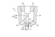
- FIG. 8 is a cross-sectional view showing the sub chamber 38 of the present embodiment and its surroundings.
- the partition wall 34 is provided with a plurality of communication holes 35, but the central communication hole 35c is not provided.
- the discharge gap 45 is provided in the sub chamber 38 at a position farther from the communication hole 35 than in the case of the first embodiment.
- the partition wall 34 is formed with protrusions 36 constituting one electrode protruding toward the center electrode 44, which is the other electrode.
- a discharge gap 45 is formed between the protrusion 36 and the center electrode 44. Then, at the time of ignition control after top dead center, the discharge spark F extends toward the predetermined communication hole 35 by the air flow flowing from the sub chamber 38 into the main chamber 31 through the predetermined communication hole 35.
- the partition wall 34 also serves as the ground electrode of the spark plug 40, but the spark plug 40 may have a ground electrode separately from the partition wall 34.
- a partition wall 34 is provided on the outside of the ground electrode, and the discharge gap 45 between the ground electrode and the center electrode 44 may be close to the communication hole 35 as the airflow support structure As.
- the engine 90 is a 4-stroke engine, but the engine 90 has one combustion cycle consisting of only a compression stroke and an expansion stroke, and intake and exhaust are performed in the latter half of the expansion stroke and the first half of the compression stroke.
- a two-stroke engine that does both may be used.
Landscapes
- Engineering & Computer Science (AREA)
- Chemical & Material Sciences (AREA)
- Combustion & Propulsion (AREA)
- Mechanical Engineering (AREA)
- General Engineering & Computer Science (AREA)
- Signal Processing (AREA)
- Spark Plugs (AREA)
- Combustion Methods Of Internal-Combustion Engines (AREA)
Abstract
Ce système d'allumage comporte une bougie d'allumage (40) et une unité de commande d'allumage (50) la commandant. Lorsqu'un moteur (90) est en état prédéterminé de fonctionnement, l'unité de commande d'allumage (50) effectue une commande d'allumage post-point mort haut où l'allumage a lieu en un point (Ta) suivant le point mort haut de compression. Le système d'allumage présente une structure d'assistance à l'écoulement d'air (As) permettant à un flux d'air de s'écouler facilement jusqu'à un espace de décharge (45) au moins au point (Ta) suivant le point mort haut de compression. Le système d'allumage est configuré pour que, grâce à la structure d'assistance à l'écoulement d'air (As) et à une synchronisation d'allumage (Taf), un flux d'air de vitesse supérieure ou égale à 5 m/s s'écoule jusqu'à l'espace de décharge (45) pendant une période d'allumage post-point mort haut, qui est une période où une étincelle de décharge (F) se produit lors de la commande d'allumage post-point mort haut.
Priority Applications (3)
| Application Number | Priority Date | Filing Date | Title |
|---|---|---|---|
| EP21747804.9A EP4098857A4 (fr) | 2020-01-29 | 2021-01-15 | Système d'allumage |
| CN202180011851.4A CN115038858A (zh) | 2020-01-29 | 2021-01-15 | 点火系统 |
| US17/874,671 US11754032B2 (en) | 2020-01-29 | 2022-07-27 | Ignition system |
Applications Claiming Priority (4)
| Application Number | Priority Date | Filing Date | Title |
|---|---|---|---|
| JP2020012918 | 2020-01-29 | ||
| JP2020-012918 | 2020-01-29 | ||
| JP2020-067668 | 2020-04-03 | ||
| JP2020067668A JP7347308B2 (ja) | 2020-01-29 | 2020-04-03 | 点火システム |
Related Child Applications (1)
| Application Number | Title | Priority Date | Filing Date |
|---|---|---|---|
| US17/874,671 Continuation US11754032B2 (en) | 2020-01-29 | 2022-07-27 | Ignition system |
Publications (1)
| Publication Number | Publication Date |
|---|---|
| WO2021153275A1 true WO2021153275A1 (fr) | 2021-08-05 |
Family
ID=77078875
Family Applications (1)
| Application Number | Title | Priority Date | Filing Date |
|---|---|---|---|
| PCT/JP2021/001282 WO2021153275A1 (fr) | 2020-01-29 | 2021-01-15 | Système d'allumage |
Country Status (4)
| Country | Link |
|---|---|
| US (1) | US11754032B2 (fr) |
| EP (1) | EP4098857A4 (fr) |
| CN (1) | CN115038858A (fr) |
| WO (1) | WO2021153275A1 (fr) |
Cited By (1)
| Publication number | Priority date | Publication date | Assignee | Title |
|---|---|---|---|---|
| EP4194672A4 (fr) * | 2020-08-07 | 2024-02-07 | Denso Corporation | Système d'allumage |
Citations (5)
| Publication number | Priority date | Publication date | Assignee | Title |
|---|---|---|---|---|
| JPH0281925A (ja) * | 1988-09-19 | 1990-03-22 | Yanmar Diesel Engine Co Ltd | 副室式ガス機関 |
| JP2003083124A (ja) * | 2001-09-06 | 2003-03-19 | Mazda Motor Corp | 火花点火式直噴エンジンの制御装置 |
| JP2010261407A (ja) * | 2009-05-11 | 2010-11-18 | Nippon Soken Inc | 副燃焼室式点火装置 |
| WO2014149290A1 (fr) * | 2013-03-15 | 2014-09-25 | Cummins, Inc. | Chambre de précombustion pour moteur à combustion interne |
| US20160053673A1 (en) * | 2013-03-12 | 2016-02-25 | Prometheus Applied Technologies, Llc | Active scavenge prechamber |
Family Cites Families (17)
| Publication number | Priority date | Publication date | Assignee | Title |
|---|---|---|---|---|
| US1403886A (en) * | 1920-05-24 | 1922-01-17 | Young Monte | Spark plug |
| DE3889038T2 (de) * | 1987-02-19 | 1994-09-08 | Hi Tech International Lab Co L | Verbrennungssystem für einen verbrennungsmotor und dabei verwendeter brenner. |
| US4930473A (en) * | 1988-12-09 | 1990-06-05 | Texas Ignitors Company, Inc. | Swirl chamber and spark plug assembly |
| KR20070043774A (ko) * | 2004-06-24 | 2007-04-25 | 우드워드 거버너 컴퍼니 | 프리-챔버 점화 플러그 |
| EP1873380B1 (fr) * | 2006-06-26 | 2016-10-05 | Nissan Motor Co., Ltd. | Dispositif et procédé de commande pour moteur à combustion interne à allumage commandé |
| JP5122367B2 (ja) | 2008-05-09 | 2013-01-16 | 大阪瓦斯株式会社 | エンジン及びエンジン用点火プラグ |
| US8584648B2 (en) * | 2010-11-23 | 2013-11-19 | Woodward, Inc. | Controlled spark ignited flame kernel flow |
| US9004042B2 (en) * | 2011-09-03 | 2015-04-14 | Prometheus Applied Technologies, Llc | Method and apparatus for achieving high power flame jets while reducing quenching and autoignition in prechamber spark plugs for gas engines |
| JP5919214B2 (ja) | 2013-03-28 | 2016-05-18 | 株式会社日本自動車部品総合研究所 | 内燃機関用のスパークプラグ |
| US8839762B1 (en) * | 2013-06-10 | 2014-09-23 | Woodward, Inc. | Multi-chamber igniter |
| JP6206158B2 (ja) * | 2013-12-17 | 2017-10-04 | トヨタ自動車株式会社 | 火花点火式内燃機関の制御システム |
| CN204478138U (zh) * | 2014-12-19 | 2015-07-15 | 中国南方航空工业(集团)有限公司 | 发动机的预燃室 |
| JP6797000B2 (ja) * | 2016-11-09 | 2020-12-09 | 株式会社Soken | 内燃機関の点火制御装置 |
| CN107332109A (zh) * | 2017-04-26 | 2017-11-07 | 周向进 | 一种喷火的火花塞及其内燃机和汽车 |
| US10666023B2 (en) | 2018-07-03 | 2020-05-26 | Ngk Spark Plug Co., Ltd. | Spark plug |
| JP7413746B2 (ja) | 2019-03-21 | 2024-01-16 | 株式会社デンソー | 内燃機関用のスパークプラグ及びこれを備えた内燃機関 |
| JP2022030604A (ja) * | 2020-08-07 | 2022-02-18 | 株式会社デンソー | 点火システム |
-
2021
- 2021-01-15 WO PCT/JP2021/001282 patent/WO2021153275A1/fr active Application Filing
- 2021-01-15 CN CN202180011851.4A patent/CN115038858A/zh active Pending
- 2021-01-15 EP EP21747804.9A patent/EP4098857A4/fr active Pending
-
2022
- 2022-07-27 US US17/874,671 patent/US11754032B2/en active Active
Patent Citations (5)
| Publication number | Priority date | Publication date | Assignee | Title |
|---|---|---|---|---|
| JPH0281925A (ja) * | 1988-09-19 | 1990-03-22 | Yanmar Diesel Engine Co Ltd | 副室式ガス機関 |
| JP2003083124A (ja) * | 2001-09-06 | 2003-03-19 | Mazda Motor Corp | 火花点火式直噴エンジンの制御装置 |
| JP2010261407A (ja) * | 2009-05-11 | 2010-11-18 | Nippon Soken Inc | 副燃焼室式点火装置 |
| US20160053673A1 (en) * | 2013-03-12 | 2016-02-25 | Prometheus Applied Technologies, Llc | Active scavenge prechamber |
| WO2014149290A1 (fr) * | 2013-03-15 | 2014-09-25 | Cummins, Inc. | Chambre de précombustion pour moteur à combustion interne |
Non-Patent Citations (1)
| Title |
|---|
| See also references of EP4098857A4 * |
Cited By (1)
| Publication number | Priority date | Publication date | Assignee | Title |
|---|---|---|---|---|
| EP4194672A4 (fr) * | 2020-08-07 | 2024-02-07 | Denso Corporation | Système d'allumage |
Also Published As
| Publication number | Publication date |
|---|---|
| EP4098857A4 (fr) | 2023-11-29 |
| US20220364538A1 (en) | 2022-11-17 |
| EP4098857A1 (fr) | 2022-12-07 |
| US11754032B2 (en) | 2023-09-12 |
| CN115038858A (zh) | 2022-09-09 |
Similar Documents
| Publication | Publication Date | Title |
|---|---|---|
| US8910612B2 (en) | Pre-chamber jet igniter and engine including combustion chamber employing the same | |
| US6948474B2 (en) | Cylinder direct injection type internal combustion engine | |
| US10436170B2 (en) | Internal combustion engine control device and internal combustion engine control method | |
| US20230184160A1 (en) | Ignition system | |
| US20170101923A1 (en) | Multiple prechambers with interacting jets | |
| US20170101922A1 (en) | Prechamber insert for an internal combustion engine | |
| WO2021153275A1 (fr) | Système d'allumage | |
| WO2018216153A1 (fr) | Procédé de commande et dispositif de commande de moteur à combustion interne | |
| US6935302B2 (en) | In-cylinder injection type internal combustion engine | |
| JP7468247B2 (ja) | 内燃機関の点火装置 | |
| JPH1182030A (ja) | 筒内直噴式火花点火エンジンの燃料噴射制御装置 | |
| EP1164276B1 (fr) | Moteur à combustion interne avec support externe pour auto-allumage stable | |
| US10309338B2 (en) | Fuel injection control device for direct-injection engine | |
| JP2007138780A (ja) | 副室式内燃機関 | |
| JP7347308B2 (ja) | 点火システム | |
| WO2021157322A1 (fr) | Système d'allumage de type à chambre auxiliaire | |
| US11773802B2 (en) | Internal combustion engine | |
| JP2008128105A (ja) | 内燃機関 | |
| JP4120452B2 (ja) | 筒内噴射式内燃機関 | |
| US20230203998A1 (en) | Internal combustion engine | |
| US20230287845A1 (en) | Internal combustion engine | |
| JP2024050166A (ja) | エンジン | |
| JPH112172A (ja) | 内燃機関の制御装置 | |
| JP2006112342A (ja) | 内燃機関の燃焼制御装置 |
Legal Events
| Date | Code | Title | Description |
|---|---|---|---|
| 121 | Ep: the epo has been informed by wipo that ep was designated in this application |
Ref document number: 21747804 Country of ref document: EP Kind code of ref document: A1 |
|
| WWE | Wipo information: entry into national phase |
Ref document number: 202217045216 Country of ref document: IN |
|
| NENP | Non-entry into the national phase |
Ref country code: DE |
|
| ENP | Entry into the national phase |
Ref document number: 2021747804 Country of ref document: EP Effective date: 20220829 |