WO2021149129A1 - 固定子およびこれを用いた回転電機 - Google Patents
固定子およびこれを用いた回転電機 Download PDFInfo
- Publication number
- WO2021149129A1 WO2021149129A1 PCT/JP2020/001814 JP2020001814W WO2021149129A1 WO 2021149129 A1 WO2021149129 A1 WO 2021149129A1 JP 2020001814 W JP2020001814 W JP 2020001814W WO 2021149129 A1 WO2021149129 A1 WO 2021149129A1
- Authority
- WO
- WIPO (PCT)
- Prior art keywords
- stator
- magnet
- wedge
- electric machine
- coil
- Prior art date
- Legal status (The legal status is an assumption and is not a legal conclusion. Google has not performed a legal analysis and makes no representation as to the accuracy of the status listed.)
- Ceased
Links
Images




Classifications
-
- H—ELECTRICITY
- H02—GENERATION; CONVERSION OR DISTRIBUTION OF ELECTRIC POWER
- H02K—DYNAMO-ELECTRIC MACHINES
- H02K1/00—Details of the magnetic circuit
- H02K1/06—Details of the magnetic circuit characterised by the shape, form or construction
- H02K1/12—Stationary parts of the magnetic circuit
- H02K1/17—Stator cores with permanent magnets
-
- H—ELECTRICITY
- H02—GENERATION; CONVERSION OR DISTRIBUTION OF ELECTRIC POWER
- H02K—DYNAMO-ELECTRIC MACHINES
- H02K16/00—Machines with more than one rotor or stator
- H02K16/02—Machines with one stator and two or more rotors
Definitions
- the present application relates to a stator and a rotary electric machine using the stator.
- the magnetic wave gearing device shown in Patent Document 1 has a stator from the outer peripheral side, a first rotor that rotates at a low speed, and a second rotor that rotates at a high speed according to a gear ratio, about a rotation axis.
- the stator has a stator coil that can output generated power or control the generated torque.
- the stator has a stator core provided with a plurality of stator slots, and both the stator coil and the stator magnet are stored in each stator slot. Therefore, one rotary electric machine can perform both shifting and power generation. Further, a chip portion made of a magnetic material as a back yoke is provided on a part of the stator coil side of the stator magnet so as to project from the wall surface of the stator slot to increase the output.
- the stator magnets arranged on the open side of the stator slot are not provided with means for fixing the stator magnets, there is a problem that problems such as the stator magnets falling off occur.
- the stator coil can be fixed to the bottom side of the stator slot.
- the stator coil can be easily inserted into the stator slot, but the stator coil is not fixed on the bottom side of the stator slot, so the stator coil moves to the open side. was there.
- the insulation coating of the stator coil will be damaged by the friction when the stator coil moves, and the insulation of the stator coil will deteriorate. There was a problem that reliability was impaired.
- the present application has been made to solve the above-mentioned problems, and an object of the present application is to obtain a stator in which a stator magnet and a stator coil in a stator slot are fixed in a stator slot by a simple manufacturing process. And.
- the stator disclosed in the present application includes a stator core provided with a plurality of stator teeth in the circumferential direction with respect to the center of rotation of the rotary electric machine, and a plurality of stator slots formed between the stator teeth.
- a stator coil arranged on the bottom side of the stator and a stator magnet arranged on the open side of each of the plurality of stator slots and having the same polarity in the radial direction are provided.
- a plate-shaped wedge is provided between the stator coil and the stator magnet so as to be fitted to two facing wall surfaces of the stator slot, and the stator magnet is adhered to the wedge. Is fixed.
- stator magnet and the stator coil in the stator slot can be fixed to the stator slot by a simple manufacturing process.
- FIG. It is a schematic diagram which shows the cross section of the rotary electric machine which concerns on Embodiment 1.
- FIG. It is a schematic diagram which shows the main part of the rotary electric machine which concerns on Embodiment 1.
- FIG. It is a schematic diagram which shows the cross section of the stator slot of the rotary electric machine which concerns on Embodiment 1.
- FIG. It is a schematic diagram which shows the cross section of the stator slot of the rotary electric machine which concerns on Embodiment 2.
- FIG. It is a schematic diagram which shows the main part of the rotary electric machine which concerns on Embodiment 3.
- FIG. 1 is a schematic view showing a cross section of the rotary electric machine 100
- FIG. 2 is a schematic view showing a main part of the rotary electric machine 100.
- FIG. 2 is an enlarged view of a portion surrounded by a broken line in FIG.
- the rotary electric machine 100 is an annular stator 1 that surrounds a rotary shaft 40 that is the center of rotation of the rotary electric machine 100, and a first rotor that is coaxially provided with the stator 1. It includes a low-speed rotor 20 and a high-speed rotor 30 which is a second rotor facing the low-speed rotor 20 and coaxially provided with the low-speed rotor 20.
- the stator 1 includes a stator core 2, a stator coil 3, and a stator magnet 4.
- the annular stator core 2 includes a plurality of stator teeth 6 at equal intervals in the circumferential direction with respect to the center of rotation of the rotary electric machine 100.
- the plurality of stator slots 5 formed between the stator teeth 6 each include a stator coil 3 and a stator magnet 4.
- the stator coil 3 is arranged on the side of the bottom portion 5a of the stator slot 5.
- the stator magnet 4 is arranged on the open side of the stator slot 5.
- the stator magnets 4 are all magnetized in the same radial direction.
- the stator magnet 4 is, for example, a neodymium sintered magnet, but is not limited thereto. Assuming that the inner diameter side of the stator magnet 4 is N pole, the inner diameter side of the adjacent stator teeth 6 is S pole, and the same number of pole logarithm Ns as the number of stator slots 5 is formed.
- the low-speed rotor 20 is provided on the inner peripheral side of the stator 1 so as to face the stator magnet 4 through a minute gap.
- the low-speed rotor 20 has a plurality of magnetic pole pieces 21 arranged at equal intervals in the circumferential direction, and rotates at a low speed by power from the outside.
- the number of the magnetic pole pieces 21 is NL.
- the high-speed rotor 30 is provided on the inner peripheral side of the low-speed rotor 20.
- the high-speed rotor 30 has a plurality of permanent magnets, high-speed rotor magnets 31, at equal intervals on the outer peripheral portion, and has a logarithm of Nh.
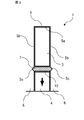
- FIG. 3 is a schematic view showing a cross section of a stator slot 5 of the rotary electric machine 100 according to the first embodiment.
- Each stator slot 5 includes a stator coil 3, a stator magnet 4, and a wedge 7.
- the plate-shaped wedge 7 is provided between the stator coil 3 and the stator magnet 4 so as to be fitted with a notch 5c of two facing wall surfaces 5b of the stator slot 5.
- the wedge 7 is made of, for example, a resin, but the material of the wedge 7 is not limited to this.
- the stator coil 3 and the stator magnet 4 face each other via a wedge 7.
- the stator magnet 4 is magnetized so as to have the same polarity in the radial direction. For example, the direction of the arrow shown in FIG. 3 is the direction of magnetism.
- stator coil 3 is stably fixed at the bottom 5a of the stator slot 5.
- the stator magnet 4 is adhered to and fixed to the wedge 7.
- the adhesive 10 for adhering the stator magnet 4 is, for example, an epoxy-based adhesive, but the adhesive is not limited to this.
- the wedge 7 is provided by inserting the stator coil 3 into the stator slot 5 and then inserting the stator coil 3 into the notch 5c from the axial direction perpendicular to the paper surface. Therefore, the wedge 7 does not prevent the stator coil 3 from being inserted into the stator slot 5, and the stator coil 3 can be easily inserted into the stator slot 5. Further, since the wedge 7 is provided by fitting, the wedge 7 can be easily installed in the stator slot 5, and the stator coil 3 is easily fixed in the stator slot 5. Since the stator magnet 4 is fixed by adhering to the wedge 7 provided between the stator coil 3 and the stator magnet 4 instead of the opening side of the stator slot 5, the stator magnet 4 rotates at a low speed. It is fixed close to the child and the high speed rotor (not shown in FIG. 3). By bringing the stator magnet 4 close to the low-speed rotor and the high-speed rotor, the generated torque can be increased.
- stator magnet 4 since the stator magnet 4 is adhered to and fixed to the wedge 7, problems such as the stator magnet 4 falling off are suppressed, and a simple manufacturing process is performed.
- the stator magnet 4 can be fixed in the stator slot 5. Further, since the stator coil 3 can be easily inserted into the stator slot 5, the stator 1 can be manufactured by a simple manufacturing process. Further, since the wedge 7 is provided by fitting, the stator 1 can be manufactured by a simple manufacturing process. Further, the stator coil 3 can be fixed to the stator slot 5 by a simple manufacturing process.
- FIG. 4 is a schematic view showing a cross section of the stator slot 5 of the rotary electric machine 100.
- the stator 1 according to the second embodiment has a configuration in which a plurality of wedges are provided between the stator coil 3 and the stator magnet 4.
- the stator slot 5 includes a stator coil 3, a stator magnet 4, and a plurality of wedges between the stator coil 3 and the stator magnet 4.
- Each stator slot 5 is provided with a plurality of wedges on the side opened from the side of the bottom portion 5a, and the stator magnet 4 is adhered to and fixed to the wedge arranged on the most open side of the plurality of wedges.
- a plurality of wedges two wedges, a wedge 7 and a wedge 8, are provided.
- the plate-shaped wedges 7 and 8 are provided so as to be fitted with notches 5c of two facing wall surfaces 5b of the stator slot 5.
- the wedge 7 and the wedge 8 are made of, for example, a resin, but the materials of the wedge 7 and the wedge 8 are not limited to this.
- the reliability of the mechanical strength in the stator slot 5 is improved because the fixing of the stator coil 3 and the stator magnet 4 does not depend on the strength of one wedge.
- the installation of two wedges has been described, the same effect can be obtained even if three or more wedges are provided.
- the temperature of the stator magnet 4 may rise due to the influence of heat generated by the Joule loss of the stator coil 3 through which an electric current flows.
- the stator magnet 4 has a characteristic that the residual magnetic flux density decreases as the temperature rises. Therefore, when the temperature rises, the magnetic force decreases and the performance of the stator 1 decreases. Deteriorates. Since the heat insulating effect can be expected by providing the space portion 9 which is an air layer, it is possible to suppress the temperature rise of the stator magnet 4 due to the heat generation of the stator coil 3.
- the stator 1 according to the second embodiment includes a plurality of wedges 7 and 8, the reliability of the mechanical strength in the stator slot 5 can be improved. Further, when the wedge 7 and the wedge 8 are provided apart from each other, the temperature rise of the stator magnet 4 due to the heat generated by the stator coil 3 can be suppressed.
- FIG. 5 is a schematic view showing a main part of the rotary electric machine 100.
- the rotary electric machine 100 according to the third embodiment has a configuration in which a plate-shaped wedge 7 is provided between the stator coil 3 and the stator magnet 4 in the stator slot 5.
- the rotary electric machine 100 has an annular stator 1 surrounding a rotation axis (not shown) which is the center of rotation of the rotary electric machine 100, and a plurality of magnetic pole pieces 21. It has a low-speed rotor 20 which is a first rotor and is provided coaxially with the stator 1 so as to face 4 and a high-speed rotor magnet 31 which is a plurality of permanent magnets, and faces the low-speed rotor 20. A high-speed rotor 30 which is a second rotor provided coaxially with the low-speed rotor 20 is provided.
- the stator 1 includes a stator core 2, a stator coil 3, a stator magnet 4, and a wedge 7.
- the annular stator core 2 includes a plurality of stator teeth 6 at equal intervals in the circumferential direction with respect to the center of rotation of the rotary electric machine 100.
- a stator slot 5 is formed between the stator teeth 6.
- the wedge 7 is provided between the stator coil 3 and the stator magnet 4 so as to be fitted with a notch 5c of two facing wall surfaces 5b of the stator slot 5.
- the wedge 7 is provided by inserting the stator coil 3 into the stator slot 5 and then inserting the stator coil 3 into the notch 5c from the axial direction perpendicular to the paper surface.
- the rotary electric machine 100 according to the third embodiment is provided with the wedge 7 and the stator magnet 4 is adhered to and fixed to the wedge 7, problems such as the stator magnet 4 falling off are suppressed.
- the stator magnet 4 can be fixed to the stator slot 5 in a simple manufacturing process, and the rotary electric machine 100 can be manufactured in a simple manufacturing process.
- the stator coil 3 can be easily inserted into the stator slot 5, the stator coil 3 can be fixed to the stator slot 5 in a simple manufacturing process, and the rotary electric machine 100 can be installed in the simple manufacturing process. Can be made.
- the wedge 7 is provided by fitting, the stator coil 3 can be fixed to the stator slot 5 in a simple manufacturing process, and the rotary electric machine 100 can be manufactured in a simple manufacturing process.
- the rotary electric machine 100 using the stator 1 described in the first embodiment has been described, but the rotary electric machine 100 using the stator 1 described in the second embodiment also has a rotary electric machine with a simple manufacturing process. 100 can be made. Further, the same effect can be obtained with a generator and a motor provided with a stator 1 having the same configuration as that of the present application.
- the rotary electric machine 100 in which the stator 1 is on the outermost circumference has been described above, the arrangement of the stator 1 is not limited to the outermost circumference, and the stator 1 is an outer rotor type rotary electric machine on the innermost circumference. It doesn't matter if there is.
- the stator core includes a plurality of stator slots opened toward the outer peripheral side of the rotary electric machine in the circumferential direction.
- the present application also describes various exemplary embodiments and examples, although the various features, embodiments, and functions described in one or more embodiments are those of a particular embodiment. It is not limited to application, but can be applied to embodiments alone or in various combinations. Therefore, innumerable variations not illustrated are envisioned within the scope of the techniques disclosed herein. For example, it is assumed that at least one component is modified, added or omitted, and further, at least one component is extracted and combined with the components of other embodiments.
- stator 1 stator, 2 stator core, 3 stator coil, 4 stator magnet, 5 stator slot, 5a bottom, 5b wall surface, 5c notch, 6 stator teeth, 7 wedge, 8 wedge, 9 space part, 10 Stator, 20 Low speed rotor, 21 magnetic pole piece, 30 high speed rotor, 31 high speed rotor magnet, 40 rotating shaft, 100 rotating electric machine
Landscapes
- Engineering & Computer Science (AREA)
- Power Engineering (AREA)
- Insulation, Fastening Of Motor, Generator Windings (AREA)
Priority Applications (2)
| Application Number | Priority Date | Filing Date | Title |
|---|---|---|---|
| PCT/JP2020/001814 WO2021149129A1 (ja) | 2020-01-21 | 2020-01-21 | 固定子およびこれを用いた回転電機 |
| JP2020532065A JP6804699B1 (ja) | 2020-01-21 | 2020-01-21 | 固定子およびこれを用いた回転電機 |
Applications Claiming Priority (1)
| Application Number | Priority Date | Filing Date | Title |
|---|---|---|---|
| PCT/JP2020/001814 WO2021149129A1 (ja) | 2020-01-21 | 2020-01-21 | 固定子およびこれを用いた回転電機 |
Publications (1)
| Publication Number | Publication Date |
|---|---|
| WO2021149129A1 true WO2021149129A1 (ja) | 2021-07-29 |
Family
ID=73836045
Family Applications (1)
| Application Number | Title | Priority Date | Filing Date |
|---|---|---|---|
| PCT/JP2020/001814 Ceased WO2021149129A1 (ja) | 2020-01-21 | 2020-01-21 | 固定子およびこれを用いた回転電機 |
Country Status (2)
| Country | Link |
|---|---|
| JP (1) | JP6804699B1 (https=) |
| WO (1) | WO2021149129A1 (https=) |
Cited By (1)
| Publication number | Priority date | Publication date | Assignee | Title |
|---|---|---|---|---|
| EP4436016A4 (en) * | 2021-11-18 | 2025-01-15 | Mitsubishi Electric Corporation | ELECTRIC LATHE WITH PERMANENT MAGNET |
Citations (6)
| Publication number | Priority date | Publication date | Assignee | Title |
|---|---|---|---|---|
| JPS5221851Y2 (https=) * | 1971-06-09 | 1977-05-19 | ||
| JPH07177695A (ja) * | 1993-12-21 | 1995-07-14 | Shinko Electric Co Ltd | 高速回転電機のステ−タウェッジの構造 |
| JP2016135014A (ja) * | 2015-01-20 | 2016-07-25 | 株式会社Ihi | 磁気波動歯車装置 |
| WO2016136384A1 (ja) * | 2015-02-25 | 2016-09-01 | 三菱電機株式会社 | 電機子および回転電機 |
| WO2018130859A1 (en) * | 2017-01-16 | 2018-07-19 | Magnomatics Limited | An electrical machine and a method of operating an electrical machine |
| JP2019161738A (ja) * | 2018-03-08 | 2019-09-19 | 三菱重工業株式会社 | 超電導回転機械用かご型ロータ、超電導回転機械用ステータ、及び超電導回転機械 |
Family Cites Families (1)
| Publication number | Priority date | Publication date | Assignee | Title |
|---|---|---|---|---|
| JPS58201555A (ja) * | 1982-05-18 | 1983-11-24 | Hitachi Ltd | 水中モ−タ |
-
2020
- 2020-01-21 JP JP2020532065A patent/JP6804699B1/ja active Active
- 2020-01-21 WO PCT/JP2020/001814 patent/WO2021149129A1/ja not_active Ceased
Patent Citations (6)
| Publication number | Priority date | Publication date | Assignee | Title |
|---|---|---|---|---|
| JPS5221851Y2 (https=) * | 1971-06-09 | 1977-05-19 | ||
| JPH07177695A (ja) * | 1993-12-21 | 1995-07-14 | Shinko Electric Co Ltd | 高速回転電機のステ−タウェッジの構造 |
| JP2016135014A (ja) * | 2015-01-20 | 2016-07-25 | 株式会社Ihi | 磁気波動歯車装置 |
| WO2016136384A1 (ja) * | 2015-02-25 | 2016-09-01 | 三菱電機株式会社 | 電機子および回転電機 |
| WO2018130859A1 (en) * | 2017-01-16 | 2018-07-19 | Magnomatics Limited | An electrical machine and a method of operating an electrical machine |
| JP2019161738A (ja) * | 2018-03-08 | 2019-09-19 | 三菱重工業株式会社 | 超電導回転機械用かご型ロータ、超電導回転機械用ステータ、及び超電導回転機械 |
Cited By (1)
| Publication number | Priority date | Publication date | Assignee | Title |
|---|---|---|---|---|
| EP4436016A4 (en) * | 2021-11-18 | 2025-01-15 | Mitsubishi Electric Corporation | ELECTRIC LATHE WITH PERMANENT MAGNET |
Also Published As
| Publication number | Publication date |
|---|---|
| JP6804699B1 (ja) | 2020-12-23 |
| JPWO2021149129A1 (https=) | 2021-07-29 |
Similar Documents
| Publication | Publication Date | Title |
|---|---|---|
| JP6804700B1 (ja) | 固定子およびこれを用いた回転電機 | |
| EP2200154A1 (en) | Axial gap motor | |
| WO2014034344A1 (ja) | 回転電機 | |
| WO2022049750A1 (ja) | 回転電機および固定子の製造方法 | |
| JP6834064B1 (ja) | 固定子およびこれを用いた回転電機 | |
| JP3722166B2 (ja) | 永久磁石形電動機の界磁 | |
| JP2008131683A (ja) | アキシャルエアギャップ型電動機 | |
| JP7262623B2 (ja) | 固定子およびこれを用いた回転電機 | |
| JP7542184B2 (ja) | 回転電機 | |
| JP6804699B1 (ja) | 固定子およびこれを用いた回転電機 | |
| JP2016524448A (ja) | 電気機械における軸受力の低減 | |
| WO2023199460A1 (ja) | 回転装置 | |
| JP2006304539A (ja) | アキシャルギャップ型回転電機のロータ構造 | |
| CN1996718A (zh) | 带变速机构的旋转电机及使用该旋转电机的驱动装置 | |
| WO2022202050A1 (ja) | 磁気ギアード回転機械、及び発電システム | |
| WO2021131298A1 (ja) | 回転電機 | |
| US20240079921A1 (en) | Motor generator | |
| JP7561669B2 (ja) | 磁気ギアードモータおよび磁気ギアードモータの製造方法 | |
| JP4807119B2 (ja) | 回転電機 | |
| JP2006304532A (ja) | アキシャルギャップ型回転電機のロータ構造 | |
| JP7345759B2 (ja) | 磁気歯車 | |
| WO2023012855A1 (ja) | 磁気波動歯車装置 | |
| JP4801824B2 (ja) | 磁気機械 | |
| JP2007259531A5 (https=) | ||
| WO2021181496A1 (ja) | 回転子およびこれを用いた回転電機 |
Legal Events
| Date | Code | Title | Description |
|---|---|---|---|
| ENP | Entry into the national phase |
Ref document number: 2020532065 Country of ref document: JP Kind code of ref document: A |
|
| 121 | Ep: the epo has been informed by wipo that ep was designated in this application |
Ref document number: 20916211 Country of ref document: EP Kind code of ref document: A1 |
|
| NENP | Non-entry into the national phase |
Ref country code: DE |
|
| 122 | Ep: pct application non-entry in european phase |
Ref document number: 20916211 Country of ref document: EP Kind code of ref document: A1 |