WO2021149129A1 - Stator and dynamo-electrical machine in which same is used - Google Patents
Stator and dynamo-electrical machine in which same is used Download PDFInfo
- Publication number
- WO2021149129A1 WO2021149129A1 PCT/JP2020/001814 JP2020001814W WO2021149129A1 WO 2021149129 A1 WO2021149129 A1 WO 2021149129A1 JP 2020001814 W JP2020001814 W JP 2020001814W WO 2021149129 A1 WO2021149129 A1 WO 2021149129A1
- Authority
- WO
- WIPO (PCT)
- Prior art keywords
- stator
- magnet
- wedge
- electric machine
- coil
- Prior art date
Links
Images


Classifications
-
- H—ELECTRICITY
- H02—GENERATION; CONVERSION OR DISTRIBUTION OF ELECTRIC POWER
- H02K—DYNAMO-ELECTRIC MACHINES
- H02K1/00—Details of the magnetic circuit
- H02K1/06—Details of the magnetic circuit characterised by the shape, form or construction
- H02K1/12—Stationary parts of the magnetic circuit
- H02K1/17—Stator cores with permanent magnets
-
- H—ELECTRICITY
- H02—GENERATION; CONVERSION OR DISTRIBUTION OF ELECTRIC POWER
- H02K—DYNAMO-ELECTRIC MACHINES
- H02K16/00—Machines with more than one rotor or stator
- H02K16/02—Machines with one stator and two or more rotors
Definitions
- the present application relates to a stator and a rotary electric machine using the stator.
- the magnetic wave gearing device shown in Patent Document 1 has a stator from the outer peripheral side, a first rotor that rotates at a low speed, and a second rotor that rotates at a high speed according to a gear ratio, about a rotation axis.
- the stator has a stator coil that can output generated power or control the generated torque.
- the stator has a stator core provided with a plurality of stator slots, and both the stator coil and the stator magnet are stored in each stator slot. Therefore, one rotary electric machine can perform both shifting and power generation. Further, a chip portion made of a magnetic material as a back yoke is provided on a part of the stator coil side of the stator magnet so as to project from the wall surface of the stator slot to increase the output.
- the stator magnets arranged on the open side of the stator slot are not provided with means for fixing the stator magnets, there is a problem that problems such as the stator magnets falling off occur.
- the stator coil can be fixed to the bottom side of the stator slot.
- the stator coil can be easily inserted into the stator slot, but the stator coil is not fixed on the bottom side of the stator slot, so the stator coil moves to the open side. was there.
- the insulation coating of the stator coil will be damaged by the friction when the stator coil moves, and the insulation of the stator coil will deteriorate. There was a problem that reliability was impaired.
- the present application has been made to solve the above-mentioned problems, and an object of the present application is to obtain a stator in which a stator magnet and a stator coil in a stator slot are fixed in a stator slot by a simple manufacturing process. And.
- the stator disclosed in the present application includes a stator core provided with a plurality of stator teeth in the circumferential direction with respect to the center of rotation of the rotary electric machine, and a plurality of stator slots formed between the stator teeth.
- a stator coil arranged on the bottom side of the stator and a stator magnet arranged on the open side of each of the plurality of stator slots and having the same polarity in the radial direction are provided.
- a plate-shaped wedge is provided between the stator coil and the stator magnet so as to be fitted to two facing wall surfaces of the stator slot, and the stator magnet is adhered to the wedge. Is fixed.
- stator magnet and the stator coil in the stator slot can be fixed to the stator slot by a simple manufacturing process.
- FIG. It is a schematic diagram which shows the cross section of the rotary electric machine which concerns on Embodiment 1.
- FIG. It is a schematic diagram which shows the main part of the rotary electric machine which concerns on Embodiment 1.
- FIG. It is a schematic diagram which shows the cross section of the stator slot of the rotary electric machine which concerns on Embodiment 1.
- FIG. It is a schematic diagram which shows the cross section of the stator slot of the rotary electric machine which concerns on Embodiment 2.
- FIG. It is a schematic diagram which shows the main part of the rotary electric machine which concerns on Embodiment 3.
- FIG. 1 is a schematic view showing a cross section of the rotary electric machine 100
- FIG. 2 is a schematic view showing a main part of the rotary electric machine 100.
- FIG. 2 is an enlarged view of a portion surrounded by a broken line in FIG.
- the rotary electric machine 100 is an annular stator 1 that surrounds a rotary shaft 40 that is the center of rotation of the rotary electric machine 100, and a first rotor that is coaxially provided with the stator 1. It includes a low-speed rotor 20 and a high-speed rotor 30 which is a second rotor facing the low-speed rotor 20 and coaxially provided with the low-speed rotor 20.
- the stator 1 includes a stator core 2, a stator coil 3, and a stator magnet 4.
- the annular stator core 2 includes a plurality of stator teeth 6 at equal intervals in the circumferential direction with respect to the center of rotation of the rotary electric machine 100.
- the plurality of stator slots 5 formed between the stator teeth 6 each include a stator coil 3 and a stator magnet 4.
- the stator coil 3 is arranged on the side of the bottom portion 5a of the stator slot 5.
- the stator magnet 4 is arranged on the open side of the stator slot 5.
- the stator magnets 4 are all magnetized in the same radial direction.
- the stator magnet 4 is, for example, a neodymium sintered magnet, but is not limited thereto. Assuming that the inner diameter side of the stator magnet 4 is N pole, the inner diameter side of the adjacent stator teeth 6 is S pole, and the same number of pole logarithm Ns as the number of stator slots 5 is formed.
- the low-speed rotor 20 is provided on the inner peripheral side of the stator 1 so as to face the stator magnet 4 through a minute gap.
- the low-speed rotor 20 has a plurality of magnetic pole pieces 21 arranged at equal intervals in the circumferential direction, and rotates at a low speed by power from the outside.
- the number of the magnetic pole pieces 21 is NL.
- the high-speed rotor 30 is provided on the inner peripheral side of the low-speed rotor 20.
- the high-speed rotor 30 has a plurality of permanent magnets, high-speed rotor magnets 31, at equal intervals on the outer peripheral portion, and has a logarithm of Nh.
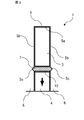
- FIG. 3 is a schematic view showing a cross section of a stator slot 5 of the rotary electric machine 100 according to the first embodiment.
- Each stator slot 5 includes a stator coil 3, a stator magnet 4, and a wedge 7.
- the plate-shaped wedge 7 is provided between the stator coil 3 and the stator magnet 4 so as to be fitted with a notch 5c of two facing wall surfaces 5b of the stator slot 5.
- the wedge 7 is made of, for example, a resin, but the material of the wedge 7 is not limited to this.
- the stator coil 3 and the stator magnet 4 face each other via a wedge 7.
- the stator magnet 4 is magnetized so as to have the same polarity in the radial direction. For example, the direction of the arrow shown in FIG. 3 is the direction of magnetism.
- stator coil 3 is stably fixed at the bottom 5a of the stator slot 5.
- the stator magnet 4 is adhered to and fixed to the wedge 7.
- the adhesive 10 for adhering the stator magnet 4 is, for example, an epoxy-based adhesive, but the adhesive is not limited to this.
- the wedge 7 is provided by inserting the stator coil 3 into the stator slot 5 and then inserting the stator coil 3 into the notch 5c from the axial direction perpendicular to the paper surface. Therefore, the wedge 7 does not prevent the stator coil 3 from being inserted into the stator slot 5, and the stator coil 3 can be easily inserted into the stator slot 5. Further, since the wedge 7 is provided by fitting, the wedge 7 can be easily installed in the stator slot 5, and the stator coil 3 is easily fixed in the stator slot 5. Since the stator magnet 4 is fixed by adhering to the wedge 7 provided between the stator coil 3 and the stator magnet 4 instead of the opening side of the stator slot 5, the stator magnet 4 rotates at a low speed. It is fixed close to the child and the high speed rotor (not shown in FIG. 3). By bringing the stator magnet 4 close to the low-speed rotor and the high-speed rotor, the generated torque can be increased.
- stator magnet 4 since the stator magnet 4 is adhered to and fixed to the wedge 7, problems such as the stator magnet 4 falling off are suppressed, and a simple manufacturing process is performed.
- the stator magnet 4 can be fixed in the stator slot 5. Further, since the stator coil 3 can be easily inserted into the stator slot 5, the stator 1 can be manufactured by a simple manufacturing process. Further, since the wedge 7 is provided by fitting, the stator 1 can be manufactured by a simple manufacturing process. Further, the stator coil 3 can be fixed to the stator slot 5 by a simple manufacturing process.
- FIG. 4 is a schematic view showing a cross section of the stator slot 5 of the rotary electric machine 100.
- the stator 1 according to the second embodiment has a configuration in which a plurality of wedges are provided between the stator coil 3 and the stator magnet 4.
- the stator slot 5 includes a stator coil 3, a stator magnet 4, and a plurality of wedges between the stator coil 3 and the stator magnet 4.
- Each stator slot 5 is provided with a plurality of wedges on the side opened from the side of the bottom portion 5a, and the stator magnet 4 is adhered to and fixed to the wedge arranged on the most open side of the plurality of wedges.
- a plurality of wedges two wedges, a wedge 7 and a wedge 8, are provided.
- the plate-shaped wedges 7 and 8 are provided so as to be fitted with notches 5c of two facing wall surfaces 5b of the stator slot 5.
- the wedge 7 and the wedge 8 are made of, for example, a resin, but the materials of the wedge 7 and the wedge 8 are not limited to this.
- the reliability of the mechanical strength in the stator slot 5 is improved because the fixing of the stator coil 3 and the stator magnet 4 does not depend on the strength of one wedge.
- the installation of two wedges has been described, the same effect can be obtained even if three or more wedges are provided.
- the temperature of the stator magnet 4 may rise due to the influence of heat generated by the Joule loss of the stator coil 3 through which an electric current flows.
- the stator magnet 4 has a characteristic that the residual magnetic flux density decreases as the temperature rises. Therefore, when the temperature rises, the magnetic force decreases and the performance of the stator 1 decreases. Deteriorates. Since the heat insulating effect can be expected by providing the space portion 9 which is an air layer, it is possible to suppress the temperature rise of the stator magnet 4 due to the heat generation of the stator coil 3.
- the stator 1 according to the second embodiment includes a plurality of wedges 7 and 8, the reliability of the mechanical strength in the stator slot 5 can be improved. Further, when the wedge 7 and the wedge 8 are provided apart from each other, the temperature rise of the stator magnet 4 due to the heat generated by the stator coil 3 can be suppressed.
- FIG. 5 is a schematic view showing a main part of the rotary electric machine 100.
- the rotary electric machine 100 according to the third embodiment has a configuration in which a plate-shaped wedge 7 is provided between the stator coil 3 and the stator magnet 4 in the stator slot 5.
- the rotary electric machine 100 has an annular stator 1 surrounding a rotation axis (not shown) which is the center of rotation of the rotary electric machine 100, and a plurality of magnetic pole pieces 21. It has a low-speed rotor 20 which is a first rotor and is provided coaxially with the stator 1 so as to face 4 and a high-speed rotor magnet 31 which is a plurality of permanent magnets, and faces the low-speed rotor 20. A high-speed rotor 30 which is a second rotor provided coaxially with the low-speed rotor 20 is provided.
- the stator 1 includes a stator core 2, a stator coil 3, a stator magnet 4, and a wedge 7.
- the annular stator core 2 includes a plurality of stator teeth 6 at equal intervals in the circumferential direction with respect to the center of rotation of the rotary electric machine 100.
- a stator slot 5 is formed between the stator teeth 6.
- the wedge 7 is provided between the stator coil 3 and the stator magnet 4 so as to be fitted with a notch 5c of two facing wall surfaces 5b of the stator slot 5.
- the wedge 7 is provided by inserting the stator coil 3 into the stator slot 5 and then inserting the stator coil 3 into the notch 5c from the axial direction perpendicular to the paper surface.
- the rotary electric machine 100 according to the third embodiment is provided with the wedge 7 and the stator magnet 4 is adhered to and fixed to the wedge 7, problems such as the stator magnet 4 falling off are suppressed.
- the stator magnet 4 can be fixed to the stator slot 5 in a simple manufacturing process, and the rotary electric machine 100 can be manufactured in a simple manufacturing process.
- the stator coil 3 can be easily inserted into the stator slot 5, the stator coil 3 can be fixed to the stator slot 5 in a simple manufacturing process, and the rotary electric machine 100 can be installed in the simple manufacturing process. Can be made.
- the wedge 7 is provided by fitting, the stator coil 3 can be fixed to the stator slot 5 in a simple manufacturing process, and the rotary electric machine 100 can be manufactured in a simple manufacturing process.
- the rotary electric machine 100 using the stator 1 described in the first embodiment has been described, but the rotary electric machine 100 using the stator 1 described in the second embodiment also has a rotary electric machine with a simple manufacturing process. 100 can be made. Further, the same effect can be obtained with a generator and a motor provided with a stator 1 having the same configuration as that of the present application.
- the rotary electric machine 100 in which the stator 1 is on the outermost circumference has been described above, the arrangement of the stator 1 is not limited to the outermost circumference, and the stator 1 is an outer rotor type rotary electric machine on the innermost circumference. It doesn't matter if there is.
- the stator core includes a plurality of stator slots opened toward the outer peripheral side of the rotary electric machine in the circumferential direction.
- the present application also describes various exemplary embodiments and examples, although the various features, embodiments, and functions described in one or more embodiments are those of a particular embodiment. It is not limited to application, but can be applied to embodiments alone or in various combinations. Therefore, innumerable variations not illustrated are envisioned within the scope of the techniques disclosed herein. For example, it is assumed that at least one component is modified, added or omitted, and further, at least one component is extracted and combined with the components of other embodiments.
- stator 1 stator, 2 stator core, 3 stator coil, 4 stator magnet, 5 stator slot, 5a bottom, 5b wall surface, 5c notch, 6 stator teeth, 7 wedge, 8 wedge, 9 space part, 10 Stator, 20 Low speed rotor, 21 magnetic pole piece, 30 high speed rotor, 31 high speed rotor magnet, 40 rotating shaft, 100 rotating electric machine
Abstract
The present invention comprises: a stator core (2) having a plurality of stator teeth (6) provided in the circumferential direction with respect to the center of rotation of a dynamo-electrical machine (100); a stator coil (3) positioned on the side of respective bottom parts (5a) of each of a plurality of stator slots (5) formed between the stator teeth (6); and stator magnets (4) positioned on the open side of each of the stator slots (5), the stator magnets (4) being provided with polarities that are identical in the radial direction. In each of the stator slots (5), a plate-form wedge (7) is provided, between the stator coil (3) and the stator magnet (4), so as to fit with two opposing wall surfaces (5b) of the stator slot (5), and the stator magnet (4) is fixed by being affixed to the wedge (7).
Description
本願は、固定子およびこれを用いた回転電機に関するものである。
The present application relates to a stator and a rotary electric machine using the stator.
従来から、回転電機が回転の中心に備えた回転軸に連結され、回転電機の回転を減速する機械式変速機が低速駆動を必要とする用途に対して用いられてきた。機械式変速機を用いた場合、機械的な摩耗などが変速機に生じるため、定期的なメンテナンスが必要となる。一方、非接触で回転子の回転速度を変速できる回転電機が、磁気波動歯車装置もしくは磁気ギアード発電機として開示されている(例えば、特許文献1参照)。
Conventionally, a mechanical transmission in which a rotary electric machine is connected to a rotary shaft provided at the center of rotation and decelerates the rotation of the rotary electric machine has been used for applications requiring low-speed drive. When a mechanical transmission is used, mechanical wear and the like occur on the transmission, so that regular maintenance is required. On the other hand, a rotating electric machine capable of shifting the rotation speed of a rotor in a non-contact manner is disclosed as a magnetic strain wave gearing device or a magnetic geared generator (see, for example, Patent Document 1).
特許文献1に示された磁気波動歯車装置は、回転軸を中心に、外周側から固定子、低速で回転する第1の回転子、および変速比に応じて高速で回転する第2の回転子を備える。固定子は、発電電力を出力する、あるいは発生トルクを制御することができる固定子コイルを有する。この回転電機を用いると、非接触で回転子の回転速度を変速できるため、機械的な摩耗などに起因したメンテナンスが不要であり、メンテナンスについての負荷の軽減を実現することができる。また、この回転電機を発電機として使用すれば、機械式変速機なしに1つの回転電機で変速と発電が可能で、発電システムは小型となり、省スペース化が実現できる。
The magnetic wave gearing device shown in Patent Document 1 has a stator from the outer peripheral side, a first rotor that rotates at a low speed, and a second rotor that rotates at a high speed according to a gear ratio, about a rotation axis. To be equipped. The stator has a stator coil that can output generated power or control the generated torque. By using this rotary electric machine, the rotation speed of the rotor can be changed without contact, so that maintenance due to mechanical wear or the like is unnecessary, and the load of maintenance can be reduced. Further, if this rotary electric machine is used as a generator, it is possible to shift and generate power with one rotary electric machine without a mechanical transmission, and the power generation system can be miniaturized and space can be saved.
上記特許文献1における回転電機の構造では、固定子は複数の固定子スロットを備えた固定子鉄心を有し、それぞれの固定子スロット内に固定子コイルと固定子磁石の両方を格納しているため、1つの回転電機で変速と発電の両方を行うことができる。また、固定子磁石の固定子コイルの側の一部に、バックヨークとして磁性体であるチップ部が固定子スロットの壁面から突出して設けられ、高出力化が図られている。しかしながら、固定子スロットの開口した側に配置されている固定子磁石は、固定子磁石を固定する手段が設けられていないため、固定子磁石が抜け落ちるなどの不具合が発生するという課題があった。
In the structure of the rotary electric machine in Patent Document 1, the stator has a stator core provided with a plurality of stator slots, and both the stator coil and the stator magnet are stored in each stator slot. Therefore, one rotary electric machine can perform both shifting and power generation. Further, a chip portion made of a magnetic material as a back yoke is provided on a part of the stator coil side of the stator magnet so as to project from the wall surface of the stator slot to increase the output. However, since the stator magnets arranged on the open side of the stator slot are not provided with means for fixing the stator magnets, there is a problem that problems such as the stator magnets falling off occur.
チップ部を設けた場合、固定子スロットの底部の側に固定子コイルを固定することができる。しかしながら、チップ部を設けたことで固定子コイルを固定子スロットに挿入することが難しくなるため、固定子の工作性が悪化するという課題があった。チップ部を設けない場合、固定子コイルの固定子スロットへの挿入は容易になるものの、固定子コイルが固定子スロットの底部の側で固定されないため、固定子コイルが開口した側に動くという課題があった。また、固定子スロットの底部の側で固定子コイルが固定されないと、固定子コイルが動いた際の摩擦により固定子コイルの絶縁被覆が損傷し、固定子コイルの絶縁が劣化するなど固定子の信頼性が損なわれるという課題があった。
If a tip portion is provided, the stator coil can be fixed to the bottom side of the stator slot. However, since it is difficult to insert the stator coil into the stator slot by providing the tip portion, there is a problem that the workability of the stator is deteriorated. If the tip is not provided, the stator coil can be easily inserted into the stator slot, but the stator coil is not fixed on the bottom side of the stator slot, so the stator coil moves to the open side. was there. Also, if the stator coil is not fixed on the bottom side of the stator slot, the insulation coating of the stator coil will be damaged by the friction when the stator coil moves, and the insulation of the stator coil will deteriorate. There was a problem that reliability was impaired.
本願は前記のような課題を解決するためになされたものであり、固定子スロット内の固定子磁石と固定子コイルを、簡易な製造工程で固定子スロットに固定した固定子を得ることを目的とする。
The present application has been made to solve the above-mentioned problems, and an object of the present application is to obtain a stator in which a stator magnet and a stator coil in a stator slot are fixed in a stator slot by a simple manufacturing process. And.
本願に開示される固定子は、回転電機の回転の中心に対して固定子ティースを周方向に複数備えた固定子鉄心と、前記固定子ティースの間に形成された複数の固定子スロットのそれぞれの底部の側に配置された固定子コイルと、複数の前記固定子スロットのそれぞれの開口した側に配置され、径方向に同一の極性を備えた固定子磁石とを備え、それぞれの前記固定子スロットにおいて、板状のウエッジが、前記固定子コイルと前記固定子磁石との間に、前記固定子スロットの対向した2つの壁面と嵌め合って設けられ、前記固定子磁石は前記ウエッジに接着して固定されるものである。
The stator disclosed in the present application includes a stator core provided with a plurality of stator teeth in the circumferential direction with respect to the center of rotation of the rotary electric machine, and a plurality of stator slots formed between the stator teeth. A stator coil arranged on the bottom side of the stator and a stator magnet arranged on the open side of each of the plurality of stator slots and having the same polarity in the radial direction are provided. In the slot, a plate-shaped wedge is provided between the stator coil and the stator magnet so as to be fitted to two facing wall surfaces of the stator slot, and the stator magnet is adhered to the wedge. Is fixed.
本願に開示される固定子によれば、固定子スロット内の固定子磁石と固定子コイルを、簡易な製造工程で固定子スロットに固定することができる。
According to the stator disclosed in the present application, the stator magnet and the stator coil in the stator slot can be fixed to the stator slot by a simple manufacturing process.
以下、本願の実施の形態による固定子およびこれを用いた回転電機を図に基づいて説明する。なお、各図において同一、または相当部材、部位については同一符号を付して説明する。
Hereinafter, a stator according to the embodiment of the present application and a rotary electric machine using the stator will be described with reference to the drawings. In each figure, the same or corresponding members and parts will be described with the same reference numerals.
実施の形態1.
図1は回転電機100の断面を示す模式図、図2は回転電機100の要部を示す模式図である。図2は、図1の破線で囲んだ箇所を拡大して示した図である。回転電機100は、図1に示すように、回転電機100の回転の中心である回転軸40を取り囲む円環状の固定子1と、固定子1と同軸に設けられた第1の回転子である低速回転子20と、低速回転子20に対向して低速回転子20と同軸に設けられた第2の回転子である高速回転子30とを備える。まず、回転電機100として磁気ギアード発電機についての一般的な構造と動作を説明する。Embodiment 1.
FIG. 1 is a schematic view showing a cross section of the rotaryelectric machine 100, and FIG. 2 is a schematic view showing a main part of the rotary electric machine 100. FIG. 2 is an enlarged view of a portion surrounded by a broken line in FIG. As shown in FIG. 1, the rotary electric machine 100 is an annular stator 1 that surrounds a rotary shaft 40 that is the center of rotation of the rotary electric machine 100, and a first rotor that is coaxially provided with the stator 1. It includes a low-speed rotor 20 and a high-speed rotor 30 which is a second rotor facing the low-speed rotor 20 and coaxially provided with the low-speed rotor 20. First, the general structure and operation of the magnetic geared generator as the rotary electric machine 100 will be described.
図1は回転電機100の断面を示す模式図、図2は回転電機100の要部を示す模式図である。図2は、図1の破線で囲んだ箇所を拡大して示した図である。回転電機100は、図1に示すように、回転電機100の回転の中心である回転軸40を取り囲む円環状の固定子1と、固定子1と同軸に設けられた第1の回転子である低速回転子20と、低速回転子20に対向して低速回転子20と同軸に設けられた第2の回転子である高速回転子30とを備える。まず、回転電機100として磁気ギアード発電機についての一般的な構造と動作を説明する。
FIG. 1 is a schematic view showing a cross section of the rotary
固定子1は、図2に示すように、固定子鉄心2、固定子コイル3、および固定子磁石4を備える。円環状の固定子鉄心2は、回転電機100の回転の中心に対して固定子ティース6を周方向に等間隔で複数備える。固定子ティース6の間に形成された複数の固定子スロット5は、それぞれが固定子コイル3と固定子磁石4を備える。固定子コイル3は、固定子スロット5の底部5aの側に配置される。固定子磁石4は、固定子スロット5の開口した側に配置される。固定子磁石4は、全て径方向の同じ向きに着磁されている。固定子磁石4は、例えばネオジウム焼結磁石であるが、これに限るものではない。固定子磁石4の内径側をN極とすると、隣接した固定子ティース6の内径側はS極となり、固定子スロット5の数と同じ数の極対数Nsが形成される。
As shown in FIG. 2, the stator 1 includes a stator core 2, a stator coil 3, and a stator magnet 4. The annular stator core 2 includes a plurality of stator teeth 6 at equal intervals in the circumferential direction with respect to the center of rotation of the rotary electric machine 100. The plurality of stator slots 5 formed between the stator teeth 6 each include a stator coil 3 and a stator magnet 4. The stator coil 3 is arranged on the side of the bottom portion 5a of the stator slot 5. The stator magnet 4 is arranged on the open side of the stator slot 5. The stator magnets 4 are all magnetized in the same radial direction. The stator magnet 4 is, for example, a neodymium sintered magnet, but is not limited thereto. Assuming that the inner diameter side of the stator magnet 4 is N pole, the inner diameter side of the adjacent stator teeth 6 is S pole, and the same number of pole logarithm Ns as the number of stator slots 5 is formed.
低速回転子20は、固定子1の内周側に固定子磁石4に対向して、微小なギャップを介して設けられる。低速回転子20は、周方向に等間隔で配置された複数の磁極片21を有し、外部からの動力により低速で回転する。この磁極片21の数を、NLとする。高速回転子30は、低速回転子20の内周側に設けられる。高速回転子30は、外周部に複数の永久磁石である高速回転子磁石31を等間隔で有し、Nhの極対数が形成される。
The low-speed rotor 20 is provided on the inner peripheral side of the stator 1 so as to face the stator magnet 4 through a minute gap. The low-speed rotor 20 has a plurality of magnetic pole pieces 21 arranged at equal intervals in the circumferential direction, and rotates at a low speed by power from the outside. The number of the magnetic pole pieces 21 is NL. The high-speed rotor 30 is provided on the inner peripheral side of the low-speed rotor 20. The high-speed rotor 30 has a plurality of permanent magnets, high-speed rotor magnets 31, at equal intervals on the outer peripheral portion, and has a logarithm of Nh.
Ns、NL、Nhの関係が、NL=Ns±Nhを満足すれば、固定子磁石4と高速回転子磁石31の磁力の相互作用により、低速回転子20に負のトルクが発生する。これに対して低速回転子20を外部からの動力により回転させることで、低速回転子20に入力を得ることができる。低速回転子20の入力に対して、高速回転子30をフリーランさせるように固定子コイル3に固定子電流を流せば、高速回転子30は低速回転子20のNL/Nh倍の回転速度で回転する。高速回転子30が低速回転子20のNL/Nh倍速で回転すると、固定子コイル3に誘導起電力が発生する。誘導起電力の発生により、固定子コイル3から発電電力が出力される。
If the relationship of Ns, NL, and Nh satisfies NL = Ns ± Nh, a negative torque is generated in the low-speed rotor 20 due to the interaction of the magnetic forces of the stator magnet 4 and the high-speed rotor magnet 31. On the other hand, by rotating the low-speed rotor 20 by an external power, an input can be obtained from the low-speed rotor 20. If a stator current is passed through the stator coil 3 so as to free run the high-speed rotor 30 with respect to the input of the low-speed rotor 20, the high-speed rotor 30 has a rotation speed that is NL / Nh times that of the low-speed rotor 20. Rotate. When the high-speed rotor 30 rotates at the NL / Nh double speed of the low-speed rotor 20, an induced electromotive force is generated in the stator coil 3. Due to the generation of the induced electromotive force, the generated power is output from the stator coil 3.
本願の要部である固定子スロット5の内部の構成について説明する。図3は実施の形態1に係る回転電機100の固定子スロット5の断面を示す模式図である。それぞれの固定子スロット5は、固定子コイル3、固定子磁石4、およびウエッジ7を備える。板状のウエッジ7は、固定子コイル3と固定子磁石4との間で、固定子スロット5の対向した2つの壁面5bの切欠き部5cと嵌め合って設けられる。ウエッジ7は、例えば、樹脂で作製されるが、ウエッジ7の材料はこれに限るものではない。固定子コイル3と固定子磁石4とは、ウエッジ7を介して対向する。固定子磁石4は、径方向に同一の極性を備えるように着磁される。例えば、図3に示した矢印の方向が着磁の方向である。
The internal configuration of the stator slot 5, which is the main part of the present application, will be described. FIG. 3 is a schematic view showing a cross section of a stator slot 5 of the rotary electric machine 100 according to the first embodiment. Each stator slot 5 includes a stator coil 3, a stator magnet 4, and a wedge 7. The plate-shaped wedge 7 is provided between the stator coil 3 and the stator magnet 4 so as to be fitted with a notch 5c of two facing wall surfaces 5b of the stator slot 5. The wedge 7 is made of, for example, a resin, but the material of the wedge 7 is not limited to this. The stator coil 3 and the stator magnet 4 face each other via a wedge 7. The stator magnet 4 is magnetized so as to have the same polarity in the radial direction. For example, the direction of the arrow shown in FIG. 3 is the direction of magnetism.
ウエッジ7を切欠き部5cと嵌め合って固定することで、固定子コイル3は固定子スロット5の底部5aで安定して固定される。固定子磁石4は、ウエッジ7に接着して固定される。固定子磁石4を接着する接着剤10は、例えば、エポキシ系の接着剤であるが、接着剤はこれに限るものではない。
By fitting and fixing the wedge 7 to the notch 5c, the stator coil 3 is stably fixed at the bottom 5a of the stator slot 5. The stator magnet 4 is adhered to and fixed to the wedge 7. The adhesive 10 for adhering the stator magnet 4 is, for example, an epoxy-based adhesive, but the adhesive is not limited to this.
固定子1の製造工程において、ウエッジ7は、固定子コイル3を固定子スロット5に挿入した後に、切欠き部5cに紙面に垂直な軸方向から挿入して設けられる。そのため、ウエッジ7は、固定子コイル3の固定子スロット5への挿入を妨げることはなく、固定子コイル3の固定子スロット5への挿入は容易である。また、ウエッジ7は嵌め合いで設けられるため、ウエッジ7の固定子スロット5への設置は容易であり、固定子コイル3は固定子スロット5に容易に固定される。固定子磁石4は、固定子スロット5の開口の側ではなく、固定子コイル3と固定子磁石4との間に設けたウエッジ7に接着して固定されるため、固定子磁石4は低速回転子および高速回転子(図3では図示せず)に接近させて固定される。固定子磁石4を低速回転子および高速回転子に接近させることで、発生するトルクを大きくすることができる。
In the manufacturing process of the stator 1, the wedge 7 is provided by inserting the stator coil 3 into the stator slot 5 and then inserting the stator coil 3 into the notch 5c from the axial direction perpendicular to the paper surface. Therefore, the wedge 7 does not prevent the stator coil 3 from being inserted into the stator slot 5, and the stator coil 3 can be easily inserted into the stator slot 5. Further, since the wedge 7 is provided by fitting, the wedge 7 can be easily installed in the stator slot 5, and the stator coil 3 is easily fixed in the stator slot 5. Since the stator magnet 4 is fixed by adhering to the wedge 7 provided between the stator coil 3 and the stator magnet 4 instead of the opening side of the stator slot 5, the stator magnet 4 rotates at a low speed. It is fixed close to the child and the high speed rotor (not shown in FIG. 3). By bringing the stator magnet 4 close to the low-speed rotor and the high-speed rotor, the generated torque can be increased.
以上のように、実施の形態1による固定子1は、固定子磁石4をウエッジ7に接着して固定しているため、固定子磁石4が抜け落ちるなどの不具合が抑制され、簡易な製造工程で固定子スロット5に固定子磁石4を固定することができる。また、固定子コイル3の固定子スロット5への挿入は容易であるため、簡易な製造工程で固定子1を作製することができる。また、ウエッジ7は嵌め合いで設けられるため、簡易な製造工程で固定子1を作製することができる。また、簡易な製造工程で固定子コイル3を固定子スロット5に固定することができる。
As described above, in the stator 1 according to the first embodiment, since the stator magnet 4 is adhered to and fixed to the wedge 7, problems such as the stator magnet 4 falling off are suppressed, and a simple manufacturing process is performed. The stator magnet 4 can be fixed in the stator slot 5. Further, since the stator coil 3 can be easily inserted into the stator slot 5, the stator 1 can be manufactured by a simple manufacturing process. Further, since the wedge 7 is provided by fitting, the stator 1 can be manufactured by a simple manufacturing process. Further, the stator coil 3 can be fixed to the stator slot 5 by a simple manufacturing process.
実施の形態2.
実施の形態2に係る固定子1について説明する。図4は、回転電機100の固定子スロット5の断面を示す模式図である。実施の形態2に係る固定子1は、複数のウエッジが固定子コイル3と固定子磁石4との間に設けられた構成になっている。Embodiment 2.
Thestator 1 according to the second embodiment will be described. FIG. 4 is a schematic view showing a cross section of the stator slot 5 of the rotary electric machine 100. The stator 1 according to the second embodiment has a configuration in which a plurality of wedges are provided between the stator coil 3 and the stator magnet 4.
実施の形態2に係る固定子1について説明する。図4は、回転電機100の固定子スロット5の断面を示す模式図である。実施の形態2に係る固定子1は、複数のウエッジが固定子コイル3と固定子磁石4との間に設けられた構成になっている。
The
固定子スロット5は、固定子コイル3、固定子磁石4、および固定子コイル3と固定子磁石4との間に複数のウエッジを備える。それぞれの固定子スロット5は底部5aの側から開口した側に複数のウエッジを備え、固定子磁石4は複数のウエッジのうち最も開口した側に配置されたウエッジに接着して固定される。ここでは複数のウエッジとして、ウエッジ7とウエッジ8の2枚のウエッジが設けられる。板状のウエッジ7とウエッジ8は、固定子スロット5の対向した2つの壁面5bの切欠き部5cと嵌め合って設けられる。ウエッジ7とウエッジ8は、例えば、樹脂で作製されるが、ウエッジ7とウエッジ8の材料はこれに限るものではない。
The stator slot 5 includes a stator coil 3, a stator magnet 4, and a plurality of wedges between the stator coil 3 and the stator magnet 4. Each stator slot 5 is provided with a plurality of wedges on the side opened from the side of the bottom portion 5a, and the stator magnet 4 is adhered to and fixed to the wedge arranged on the most open side of the plurality of wedges. Here, as a plurality of wedges, two wedges, a wedge 7 and a wedge 8, are provided. The plate-shaped wedges 7 and 8 are provided so as to be fitted with notches 5c of two facing wall surfaces 5b of the stator slot 5. The wedge 7 and the wedge 8 are made of, for example, a resin, but the materials of the wedge 7 and the wedge 8 are not limited to this.
複数のウエッジを設けたことで、固定子コイル3と固定子磁石4の固定を1つのウエッジの強度に頼ることがなくなるため、固定子スロット5内の機械強度の信頼性が向上する。なお、2枚のウエッジの設置について説明したが、ウエッジを3枚以上に設けても同様の効果を奏する。
By providing a plurality of wedges, the reliability of the mechanical strength in the stator slot 5 is improved because the fixing of the stator coil 3 and the stator magnet 4 does not depend on the strength of one wedge. Although the installation of two wedges has been described, the same effect can be obtained even if three or more wedges are provided.
ウエッジ7とウエッジ8は接近させて設けるのではなく、図4に示すように、空間部9を介して離間して設けるのが望ましい。電流が流れた固定子コイル3のジュール損による発熱の影響で、固定子磁石4の温度が高くなることがある。固定子磁石4の温度が高くなった場合、固定子磁石4は温度が高くなるにつれて残留磁束密度が小さくなる特性を有しているため、温度が高くなると磁力が低下し、固定子1の性能が劣化する。空気層である空間部9を設けることで断熱効果が見込めるため、固定子コイル3の発熱に起因した固定子磁石4の昇温を抑制することができる。
It is desirable that the wedge 7 and the wedge 8 are not provided close to each other, but are provided apart from each other via the space portion 9 as shown in FIG. The temperature of the stator magnet 4 may rise due to the influence of heat generated by the Joule loss of the stator coil 3 through which an electric current flows. When the temperature of the stator magnet 4 rises, the stator magnet 4 has a characteristic that the residual magnetic flux density decreases as the temperature rises. Therefore, when the temperature rises, the magnetic force decreases and the performance of the stator 1 decreases. Deteriorates. Since the heat insulating effect can be expected by providing the space portion 9 which is an air layer, it is possible to suppress the temperature rise of the stator magnet 4 due to the heat generation of the stator coil 3.
以上のように、実施の形態2による固定子1は、ウエッジ7とウエッジ8の複数のウエッジを備えたため、固定子スロット5内の機械強度の信頼性を向上することができる。また、ウエッジ7とウエッジ8とを離間させて設けた場合、固定子コイル3の発熱に起因した固定子磁石4の昇温を抑制することができる。
As described above, since the stator 1 according to the second embodiment includes a plurality of wedges 7 and 8, the reliability of the mechanical strength in the stator slot 5 can be improved. Further, when the wedge 7 and the wedge 8 are provided apart from each other, the temperature rise of the stator magnet 4 due to the heat generated by the stator coil 3 can be suppressed.
実施の形態3.
実施の形態3では、実施の形態1で説明した固定子1を用いた回転電機100について説明する。図5は回転電機100の要部を示す模式図である。実施の形態3に係る回転電機100は、固定子スロット5内の固定子コイル3と固定子磁石4との間に板状のウエッジ7を備えた構成になっている。Embodiment 3.
In the third embodiment, the rotaryelectric machine 100 using the stator 1 described in the first embodiment will be described. FIG. 5 is a schematic view showing a main part of the rotary electric machine 100. The rotary electric machine 100 according to the third embodiment has a configuration in which a plate-shaped wedge 7 is provided between the stator coil 3 and the stator magnet 4 in the stator slot 5.
実施の形態3では、実施の形態1で説明した固定子1を用いた回転電機100について説明する。図5は回転電機100の要部を示す模式図である。実施の形態3に係る回転電機100は、固定子スロット5内の固定子コイル3と固定子磁石4との間に板状のウエッジ7を備えた構成になっている。
In the third embodiment, the rotary
回転電機100は、図5に示すように、回転電機100の回転の中心である回転軸(図示せず)を取り囲む円環状の固定子1と、複数の磁極片21を有し、固定子磁石4と対向して固定子1と同軸に設けられた第1の回転子である低速回転子20と、複数の永久磁石である高速回転子磁石31を有し、低速回転子20と対向して低速回転子20と同軸に設けられた第2の回転子である高速回転子30とを備える。固定子1は、固定子鉄心2、固定子コイル3、固定子磁石4、およびウエッジ7を備える。円環状の固定子鉄心2は、回転電機100の回転の中心に対して固定子ティース6を周方向に等間隔で複数備える。固定子ティース6の間に、固定子スロット5が形成される。ウエッジ7は、固定子コイル3と固定子磁石4との間で、固定子スロット5の対向した2つの壁面5bの切欠き部5cと嵌め合って設けられる。固定子1の製造工程において、ウエッジ7は、固定子コイル3を固定子スロット5に挿入した後に、切欠き部5cに紙面に垂直な軸方向から挿入して設けられる。
As shown in FIG. 5, the rotary electric machine 100 has an annular stator 1 surrounding a rotation axis (not shown) which is the center of rotation of the rotary electric machine 100, and a plurality of magnetic pole pieces 21. It has a low-speed rotor 20 which is a first rotor and is provided coaxially with the stator 1 so as to face 4 and a high-speed rotor magnet 31 which is a plurality of permanent magnets, and faces the low-speed rotor 20. A high-speed rotor 30 which is a second rotor provided coaxially with the low-speed rotor 20 is provided. The stator 1 includes a stator core 2, a stator coil 3, a stator magnet 4, and a wedge 7. The annular stator core 2 includes a plurality of stator teeth 6 at equal intervals in the circumferential direction with respect to the center of rotation of the rotary electric machine 100. A stator slot 5 is formed between the stator teeth 6. The wedge 7 is provided between the stator coil 3 and the stator magnet 4 so as to be fitted with a notch 5c of two facing wall surfaces 5b of the stator slot 5. In the manufacturing process of the stator 1, the wedge 7 is provided by inserting the stator coil 3 into the stator slot 5 and then inserting the stator coil 3 into the notch 5c from the axial direction perpendicular to the paper surface.
以上のように、実施の形態3による回転電機100では、ウエッジ7を備え、固定子磁石4をウエッジ7に接着して固定しているため、固定子磁石4が抜け落ちるなどの不具合が抑制され、簡易な製造工程で固定子スロット5に固定子磁石4を固定することができ、ひいては簡易な製造工程で回転電機100を作製することができる。また、固定子コイル3の固定子スロット5への挿入は容易であるため、簡易な製造工程で固定子コイル3を固定子スロット5に固定することができ、簡易な製造工程で回転電機100を作製することができる。また、ウエッジ7は嵌め合いで設けられるため、簡易な製造工程で固定子コイル3を固定子スロット5に固定することができ、簡易な製造工程で回転電機100を作製することができる。
As described above, since the rotary electric machine 100 according to the third embodiment is provided with the wedge 7 and the stator magnet 4 is adhered to and fixed to the wedge 7, problems such as the stator magnet 4 falling off are suppressed. The stator magnet 4 can be fixed to the stator slot 5 in a simple manufacturing process, and the rotary electric machine 100 can be manufactured in a simple manufacturing process. Further, since the stator coil 3 can be easily inserted into the stator slot 5, the stator coil 3 can be fixed to the stator slot 5 in a simple manufacturing process, and the rotary electric machine 100 can be installed in the simple manufacturing process. Can be made. Further, since the wedge 7 is provided by fitting, the stator coil 3 can be fixed to the stator slot 5 in a simple manufacturing process, and the rotary electric machine 100 can be manufactured in a simple manufacturing process.
以上では、実施の形態1で説明した固定子1を用いた回転電機100について説明したが、実施の形態2で説明した固定子1を用いた回転電機100においても、簡易な製造工程で回転電機100を作製することができる。また、本願と同様の構成の固定子1を備えた発電機、モータにおいても同様の効果を奏する。また、以上では固定子1が最外周にある回転電機100について記載したが、固定子1の配置は最外周に限るものではなく、固定子1が最内周にあるアウターロータ形の回転電機であっても構わない。固定子1を最内周に設けた場合、固定子鉄心は回転電機の外周側に向けて開口した固定子スロットを周方向に複数備える。
In the above, the rotary electric machine 100 using the stator 1 described in the first embodiment has been described, but the rotary electric machine 100 using the stator 1 described in the second embodiment also has a rotary electric machine with a simple manufacturing process. 100 can be made. Further, the same effect can be obtained with a generator and a motor provided with a stator 1 having the same configuration as that of the present application. Further, although the rotary electric machine 100 in which the stator 1 is on the outermost circumference has been described above, the arrangement of the stator 1 is not limited to the outermost circumference, and the stator 1 is an outer rotor type rotary electric machine on the innermost circumference. It doesn't matter if there is. When the stator 1 is provided on the innermost circumference, the stator core includes a plurality of stator slots opened toward the outer peripheral side of the rotary electric machine in the circumferential direction.
また本願は、様々な例示的な実施の形態及び実施例が記載されているが、1つ、または複数の実施の形態に記載された様々な特徴、態様、及び機能は特定の実施の形態の適用に限られるのではなく、単独で、または様々な組み合わせで実施の形態に適用可能である。
従って、例示されていない無数の変形例が、本願明細書に開示される技術の範囲内において想定される。例えば、少なくとも1つの構成要素を変形する場合、追加する場合または省略する場合、さらには、少なくとも1つの構成要素を抽出し、他の実施の形態の構成要素と組み合わせる場合が含まれるものとする。 The present application also describes various exemplary embodiments and examples, although the various features, embodiments, and functions described in one or more embodiments are those of a particular embodiment. It is not limited to application, but can be applied to embodiments alone or in various combinations.
Therefore, innumerable variations not illustrated are envisioned within the scope of the techniques disclosed herein. For example, it is assumed that at least one component is modified, added or omitted, and further, at least one component is extracted and combined with the components of other embodiments.
1 固定子、2 固定子鉄心、3 固定子コイル、4 固定子磁石、5 固定子スロット、5a 底部、5b 壁面、5c 切欠き部、6 固定子ティース、7 ウエッジ、8 ウエッジ、9 空間部、10 接着剤、20 低速回転子、21 磁極片、30 高速回転子、31 高速回転子磁石、40 回転軸、100 回転電機
1 stator, 2 stator core, 3 stator coil, 4 stator magnet, 5 stator slot, 5a bottom, 5b wall surface, 5c notch, 6 stator teeth, 7 wedge, 8 wedge, 9 space part, 10 Stator, 20 Low speed rotor, 21 magnetic pole piece, 30 high speed rotor, 31 high speed rotor magnet, 40 rotating shaft, 100 rotating electric machine
Claims (3)
- 回転電機の回転の中心に対して固定子ティースを周方向に複数備えた固定子鉄心と、
前記固定子ティースの間に形成された複数の固定子スロットのそれぞれの底部の側に配置された固定子コイルと、
複数の前記固定子スロットのそれぞれの開口した側に配置され、径方向に同一の極性を備えた固定子磁石と、を備え、
それぞれの前記固定子スロットにおいて、
板状のウエッジが、前記固定子コイルと前記固定子磁石との間に、前記固定子スロットの対向した2つの壁面と嵌め合って設けられ、
前記固定子磁石は前記ウエッジに接着して固定されていることを特徴とする固定子。 A stator core with multiple stator teeth in the circumferential direction with respect to the center of rotation of the rotary electric machine,
A stator coil arranged on the bottom side of each of the plurality of stator slots formed between the stator teeth, and a stator coil.
A stator magnet, which is arranged on the open side of each of the plurality of stator slots and has the same polarity in the radial direction, is provided.
In each of the stator slots
A plate-shaped wedge is provided between the stator coil and the stator magnet so as to be fitted to two facing wall surfaces of the stator slot.
The stator magnet is a stator characterized in that it is adhered and fixed to the wedge. - それぞれの前記固定子スロットは底部の側から開口した側に複数の前記ウエッジを備え、
前記固定子磁石は複数の前記ウエッジのうち最も前記開口した側に配置されたウエッジに接着して固定されていることを特徴とする請求項1に記載の固定子。 Each of the stator slots has a plurality of the wedges on the side that opens from the bottom side.
The stator according to claim 1, wherein the stator magnet is adhered and fixed to a wedge arranged on the most open side of the plurality of wedges. - 請求項1または請求項2に記載した固定子と、
複数の磁極片を有し、前記固定子磁石と対向して前記固定子と同軸に設けられた第1の回転子と、
複数の永久磁石を有し、前記第1の回転子と対向して前記第1の回転子と同軸に設けられた第2の回転子と、を備えたことを特徴とする回転電機。 The stator according to claim 1 or 2, and the stator.
A first rotor having a plurality of magnetic pole pieces and provided so as to face the stator magnet and coaxially with the stator.
A rotating electric machine having a plurality of permanent magnets and provided with a second rotor facing the first rotor and provided coaxially with the first rotor.
Priority Applications (2)
| Application Number | Priority Date | Filing Date | Title |
|---|---|---|---|
| PCT/JP2020/001814 WO2021149129A1 (en) | 2020-01-21 | 2020-01-21 | Stator and dynamo-electrical machine in which same is used |
| JP2020532065A JP6804699B1 (en) | 2020-01-21 | 2020-01-21 | Stator and rotary machine using it |
Applications Claiming Priority (1)
| Application Number | Priority Date | Filing Date | Title |
|---|---|---|---|
| PCT/JP2020/001814 WO2021149129A1 (en) | 2020-01-21 | 2020-01-21 | Stator and dynamo-electrical machine in which same is used |
Publications (1)
| Publication Number | Publication Date |
|---|---|
| WO2021149129A1 true WO2021149129A1 (en) | 2021-07-29 |
Family
ID=73836045
Family Applications (1)
| Application Number | Title | Priority Date | Filing Date |
|---|---|---|---|
| PCT/JP2020/001814 WO2021149129A1 (en) | 2020-01-21 | 2020-01-21 | Stator and dynamo-electrical machine in which same is used |
Country Status (2)
| Country | Link |
|---|---|
| JP (1) | JP6804699B1 (en) |
| WO (1) | WO2021149129A1 (en) |
Citations (6)
| Publication number | Priority date | Publication date | Assignee | Title |
|---|---|---|---|---|
| JPS5221851Y2 (en) * | 1971-06-09 | 1977-05-19 | ||
| JPH07177695A (en) * | 1993-12-21 | 1995-07-14 | Shinko Electric Co Ltd | Structure of stator wedge for high speed electric rotating machine |
| JP2016135014A (en) * | 2015-01-20 | 2016-07-25 | 株式会社Ihi | Magnetic wave gear device |
| WO2016136384A1 (en) * | 2015-02-25 | 2016-09-01 | 三菱電機株式会社 | Armature and rotating electric machine |
| WO2018130859A1 (en) * | 2017-01-16 | 2018-07-19 | Magnomatics Limited | An electrical machine and a method of operating an electrical machine |
| JP2019161738A (en) * | 2018-03-08 | 2019-09-19 | 三菱重工業株式会社 | Superconducting rotary machine cage rotor, superconducting rotary machine stator, and superconducting rotary machine |
Family Cites Families (1)
| Publication number | Priority date | Publication date | Assignee | Title |
|---|---|---|---|---|
| JPS58201555A (en) * | 1982-05-18 | 1983-11-24 | Hitachi Ltd | Underwater motor |
-
2020
- 2020-01-21 JP JP2020532065A patent/JP6804699B1/en active Active
- 2020-01-21 WO PCT/JP2020/001814 patent/WO2021149129A1/en active Application Filing
Patent Citations (6)
| Publication number | Priority date | Publication date | Assignee | Title |
|---|---|---|---|---|
| JPS5221851Y2 (en) * | 1971-06-09 | 1977-05-19 | ||
| JPH07177695A (en) * | 1993-12-21 | 1995-07-14 | Shinko Electric Co Ltd | Structure of stator wedge for high speed electric rotating machine |
| JP2016135014A (en) * | 2015-01-20 | 2016-07-25 | 株式会社Ihi | Magnetic wave gear device |
| WO2016136384A1 (en) * | 2015-02-25 | 2016-09-01 | 三菱電機株式会社 | Armature and rotating electric machine |
| WO2018130859A1 (en) * | 2017-01-16 | 2018-07-19 | Magnomatics Limited | An electrical machine and a method of operating an electrical machine |
| JP2019161738A (en) * | 2018-03-08 | 2019-09-19 | 三菱重工業株式会社 | Superconducting rotary machine cage rotor, superconducting rotary machine stator, and superconducting rotary machine |
Also Published As
| Publication number | Publication date |
|---|---|
| JP6804699B1 (en) | 2020-12-23 |
| JPWO2021149129A1 (en) | 2021-07-29 |
Similar Documents
| Publication | Publication Date | Title |
|---|---|---|
| WO2021149128A1 (en) | Stator and rotating electrical machine using same | |
| US8040008B2 (en) | Axial gap motor | |
| WO2014034344A1 (en) | Rotating electric machine | |
| US20080238232A1 (en) | Motor, rotor structure and magnetic machine | |
| JP2008131683A (en) | Axial air gap type motor | |
| WO2022049750A1 (en) | Rotating electric machine and rotor manufacturing method | |
| JP3722166B2 (en) | Field of permanent magnet motor | |
| JP2006304539A (en) | Rotor structure of axial gap rotating electric machine | |
| WO2021149130A1 (en) | Stator and rotating electric machine using same | |
| WO2021149131A1 (en) | Stator and rotating electrical machine using the same | |
| WO2021149129A1 (en) | Stator and dynamo-electrical machine in which same is used | |
| JP2016524448A (en) | Reduction of bearing force in electric machines | |
| JP2006304532A (en) | Rotor structure of axial gap rotating electric machine | |
| JP4807119B2 (en) | Rotating electric machine | |
| JP2007259531A5 (en) | ||
| JP6094432B2 (en) | Rotor and electric motor using this rotor | |
| WO2021181496A1 (en) | Rotor and rotating electrical machine using same | |
| JP4801824B2 (en) | Magnetic machine | |
| JP2006304562A (en) | Rotor structure of axial gap rotating electric machine | |
| WO2023012855A1 (en) | Magnetic strain wave gear device | |
| US20240079921A1 (en) | Motor generator | |
| WO2023100274A1 (en) | Rotor and magnetic wave gear device | |
| WO2023199460A1 (en) | Rotation device | |
| WO2021131298A1 (en) | Rotary electric machine | |
| WO2022202050A1 (en) | Magnetic geared rotary machine and power generation system |
Legal Events
| Date | Code | Title | Description |
|---|---|---|---|
| ENP | Entry into the national phase |
Ref document number: 2020532065 Country of ref document: JP Kind code of ref document: A |
|
| 121 | Ep: the epo has been informed by wipo that ep was designated in this application |
Ref document number: 20916211 Country of ref document: EP Kind code of ref document: A1 |
|
| NENP | Non-entry into the national phase |
Ref country code: DE |
|
| 122 | Ep: pct application non-entry in european phase |
Ref document number: 20916211 Country of ref document: EP Kind code of ref document: A1 |