WO2021145315A1 - 発泡成形用金型および発泡成形品の製造方法 - Google Patents
発泡成形用金型および発泡成形品の製造方法 Download PDFInfo
- Publication number
- WO2021145315A1 WO2021145315A1 PCT/JP2021/000732 JP2021000732W WO2021145315A1 WO 2021145315 A1 WO2021145315 A1 WO 2021145315A1 JP 2021000732 W JP2021000732 W JP 2021000732W WO 2021145315 A1 WO2021145315 A1 WO 2021145315A1
- Authority
- WO
- WIPO (PCT)
- Prior art keywords
- mold
- nickel
- foam molding
- plated
- foam
- Prior art date
Links
Images


Classifications
-
- B—PERFORMING OPERATIONS; TRANSPORTING
- B29—WORKING OF PLASTICS; WORKING OF SUBSTANCES IN A PLASTIC STATE IN GENERAL
- B29C—SHAPING OR JOINING OF PLASTICS; SHAPING OF MATERIAL IN A PLASTIC STATE, NOT OTHERWISE PROVIDED FOR; AFTER-TREATMENT OF THE SHAPED PRODUCTS, e.g. REPAIRING
- B29C33/00—Moulds or cores; Details thereof or accessories therefor
- B29C33/38—Moulds or cores; Details thereof or accessories therefor characterised by the material or the manufacturing process
-
- B—PERFORMING OPERATIONS; TRANSPORTING
- B29—WORKING OF PLASTICS; WORKING OF SUBSTANCES IN A PLASTIC STATE IN GENERAL
- B29C—SHAPING OR JOINING OF PLASTICS; SHAPING OF MATERIAL IN A PLASTIC STATE, NOT OTHERWISE PROVIDED FOR; AFTER-TREATMENT OF THE SHAPED PRODUCTS, e.g. REPAIRING
- B29C33/00—Moulds or cores; Details thereof or accessories therefor
- B29C33/42—Moulds or cores; Details thereof or accessories therefor characterised by the shape of the moulding surface, e.g. ribs or grooves
-
- B—PERFORMING OPERATIONS; TRANSPORTING
- B29—WORKING OF PLASTICS; WORKING OF SUBSTANCES IN A PLASTIC STATE IN GENERAL
- B29C—SHAPING OR JOINING OF PLASTICS; SHAPING OF MATERIAL IN A PLASTIC STATE, NOT OTHERWISE PROVIDED FOR; AFTER-TREATMENT OF THE SHAPED PRODUCTS, e.g. REPAIRING
- B29C44/00—Shaping by internal pressure generated in the material, e.g. swelling or foaming ; Producing porous or cellular expanded plastics articles
- B29C44/34—Auxiliary operations
- B29C44/58—Moulds
Definitions
- the present invention relates to a mold for foam molding and a method for manufacturing a foam molded product.
- Patent Document 1 discloses a urethane foam type used for manufacturing a foam molded product.
- the foam raw material that fills the cavity penetrates into a slight gap of the divided surface of the molding mold due to the pressure in the cavity increased by the foaming.
- the foam raw material that has entered the gap remains as burrs in the foam molded product. Burrs are often removed manually, and the occurrence of burrs leads to an increase in manufacturing time and cost. Therefore, the present invention provides a foam molding die in which burrs are less likely to occur in the foam molded product, and a method for manufacturing the foam molded product using the mold.
- a mold for foam molding used for foam molding which has a first mold and a second mold made of metal.
- the first mold contact portion provided on the first mold and the second mold contact portion provided on the second mold come into contact with each other to form the inside of the foam molding mold. Cavity can be sealed,
- the first-type contact portion is formed of a high-hardness metal portion having a hardness higher than that of the second-type metal.
- the second type contact portion is provided with a recess having a shape corresponding to the portion of the high hardness metal portion that comes into contact with the second type contact portion.
- a mold for foam molding is provided.
- the main body of the first type includes a chamfered portion having a chamfered corner formed by a cavity surface and a non-cavity surface.
- the high hardness metal portion may be arranged on the chamfered portion.
- the contact length between the chamfered portion and the high-hardness metal portion may be 0.5 mm or more in a cross section parallel to the mold opening direction when the foam molding die is opened.
- the first mold may be provided with a recess corresponding to the high hardness metal portion in the arrangement portion of the high hardness metal portion.
- the first and second molds may be made of aluminum, and the high hardness metal portion may be made of nickel.
- a method for manufacturing an effervescent molded product using the above-mentioned effervescent molding die The first mold and the second mold are molded so that the high hardness metal portion fits into the recess provided in the second mold.
- a foam-molded product obtained by pouring a foamed resin raw material into the cavity sealed by the first-type contact portion and the second-type contact portion, foaming the foamed resin raw material, and curing the foamed resin raw material to obtain the foam-molded product. Manufacturing method is provided.
- a mold for foam molding in which burrs are less likely to occur in the foam molded product, and a method for manufacturing the foam molded product using the mold.
- FIG. 1 is a diagram showing a foam molding die 1 according to an embodiment of the present invention.
- FIG. 1 shows a cross section of the foam molding die 1 along the mold opening direction A.
- the foam molding die 1 according to the present embodiment is made of aluminum.
- the foam molding die 1 is used to form the foam molded product R from a foamed resin raw material such as polyurethane foam.
- the foam molding die 1 has a fixed mold (first mold) 2 and a mobile mold (second mold) 3.
- a cavity C is formed inside the fixed mold 2.
- a portion that comes into contact with each other when the fixed mold 2 and the mobile mold 3 are molded is called a contact portion.
- the fixed mold 2 has a fixed side contact portion (first mold contact portion) 21 that comes into contact with the mobile mold 3 at the time of mold matching.
- the mobile mold 3 has a moving side contact portion (second mold contact portion) 31 that comes into contact with the fixed mold 2 at the time of mold matching.
- the cavity C can be sealed by the contact between the fixed side contact portion 21 and the moving side contact portion 31.
- the fixed-side contact portion 21 and the moving-side contact portion 31 exist so as to be continuous with the opening of the cavity C so as to surround the cavity C.
- the fixed die 2 and the moving die 3 are connected by a hinge 4.
- the mold is tightened and the mold is opened.
- the movable mold 3 moves clockwise around the hinge 4 provided at the right end of the fixed mold 2 and the mobile mold 3 to open the mold.
- the mold opening direction A is the direction in which the mold is opened from the molded state.
- the vertical direction is the mold opening direction A.
- the fixed mold 2 has a nickel-plated portion 5 (an example of a high-hardness metal portion).
- the nickel-plated portion 5 is provided on the fixed mold 2.
- the nickel-plated portion 5 is a portion having a higher hardness than aluminum, which is a metal of the mobile type 3 (second type).
- the nickel-plated portion 5 is formed by plating the opening portion of the cavity C in the zincated aluminum fixed mold 2 with nickel.
- the nickel-plated portion 5 has a shape protruding toward the movable mold 3. As shown in FIG.
- a recess 6 having a shape corresponding to the fixed side contact portion 21 in the nickel plating portion 5.
- the nickel-plated portion 5 also exists so as to be continuous with the opening of the cavity C so as to surround the cavity C along the fixed side contact portion 21 that linearly exists in the opening of the cavity C so as to surround the cavity C. ing.
- the movable mold 3 and the fixed mold 2 in which the recess 6 is not provided are molded, and in this state, a large force is applied in the mold clamping direction (direction opposite to the mold opening direction A, downward in FIG. 1). It is formed by acting on the mobile type 3.
- the mobile type 3 is made of aluminum, while the nickel-plated portion 5 is made of nickel.
- the Vickers hardness of the aluminum mobile type 3 is about 50 to 80 Hv, and the hardness of the nickel-plated portion 5 is 400 Hv or more. That is, the aluminum mobile type 3 is softer than the nickel-plated portion 5.
- the nickel-plated portion 5 bites into the mobile mold 3, and the portion of the mobile mold 3 in which the nickel-plated portion 5 is in contact. Is crushed and the shape of the nickel-plated portion 5 is transferred, and the recess 6 is formed. Therefore, the shape of the recess 6 formed in the movable mold 3 corresponds to the shape of the portion of the nickel-plated portion 5 that contacts the moving side contact portion 31, and the nickel-plated portion 5 and the recess 6 have a gap at the time of mold clamping. Will come into contact without.
- the "shape corresponding to the portion of the nickel-plated portion 5 that contacts the moving side contact portion 31" of the recess 6 is combined with the nickel-plated portion 5 even if the shape does not completely match the nickel-plated portion 5. Occasionally, the shape may be such that the nickel-plated portion 5 and the recess 6 are in close contact with each other.
- the nickel-plated portion 5 is fitted into the recess 6 at the time of mold clamping, and a gap is unlikely to occur between the nickel-plated portion 5 and the recess 6. Therefore, the cavity C is sealed with high accuracy. Therefore, the foamed resin raw material filled in the cavity C during foam molding is less likely to leak to the outside, and the generation of burrs is suppressed.
- the fixed mold 2 and the mobile mold 3 are molded so that the nickel-plated portion 5 fits into the recess 6.
- the foamed resin raw material is poured into the cavity C sealed by the fixed side contact portion 21 and the moving side contact portion 31, and the foamed resin raw material is foamed and cured to obtain a foamed molded product.
- burrs are less likely to occur in the foam-molded product, and a post-process such as deburring can be eliminated after molding, or the load on the post-process can be reduced.
- FIG. 2 is an enlarged view of the nickel-plated portion 5.
- the main body of the fixed mold 2 includes a chamfered portion 8 having a chamfered corner formed by a cavity surface 9 and a non-cavity surface 10, and the nickel-plated portion 5 is attached to the chamfered portion 8.
- the chamfered portion 8 is provided at an angle formed by a part of the cavity surface 9 and the non-cavity surface 10 which is a mold split surface PL adjacent thereto.
- the angle ⁇ of the chamfered portion 8 with respect to the cavity surface 9 is preferably 1 degree or more and 10 degrees or less.
- the nickel-plated portion 5 When the nickel-plated portion 5 is provided at the corner formed by the cavity surface 9 and the non-cavity surface 10 adjacent thereto, the nickel-plated portion 5 projects into the cavity C toward the tip of the corner when nickel is plated. It will be formed thickly. If the nickel-plated portion 5 is formed in such a shape, an undercut may occur in the cavity C. Therefore, in the present embodiment, by chamfering the cavity surface 9, undercut is less likely to occur in the cavity C.
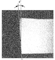
- FIG. 3 is a photograph showing a nickel-plated portion 5 formed without chamfering.
- FIG. 4 is a photograph showing a nickel-plated portion 5 formed in a state where ⁇ is chamfered at 4 degrees.
- FIG. 5 is a photograph showing a nickel-plated portion 5 formed in a state where ⁇ is chamfered at 9 degrees.
- the amount of protrusion of the nickel-plated portion 5 in the direction orthogonal to the cavity surface 9 increases toward the corner. If the nickel-plated portion 5 protrudes greatly toward the cavity C, an undercut may occur in the cavity C.
- the nickel-plated portion 5 fills the region removed by the chamfering. Therefore, even when the nickel-plated portion 5 is formed thick enough to have sufficient strength, the amount of protrusion of the nickel-plated portion 5 into the cavity C does not become too large, and undercuts are unlikely to occur in the cavity C. Further, since the nickel-plated portion 5 fills most of the region removed by the chamfering process, the nickel-plated portion 5 is not extremely dented as compared with the cavity surface 9, and defects are less likely to occur in the foam molded product.
- the chamfered area is large when the ⁇ is chamfered at 9 degrees.
- the nickel-plated portion 5 also forms a part of the cavity surface 9.
- the chamfering angle ⁇ becomes too large, the nickel-plated portion 5 may not be able to fill the chamfered and removed region. Then, the surface formed by the nickel-plated portion 5 is recessed more than the cavity surface 9. Therefore, there is a possibility that the foam molded product formed by the cavity C may be defective.
- the chamfer angle ⁇ exceeds 10 degrees, which is larger than 9 degrees, defects are likely to occur in the foam molded product.
- the chamfering angle ⁇ provided on the cavity surface 9 is preferably 1 degree or more and 10 degrees or less. It is more preferable that the cavity surface 9 is chamfered at an angle of 2 degrees or more and 8 degrees or less. It is more preferable that the cavity surface 9 is chamfered at an angle of 3 degrees or more and 7 degrees or less.
- FIG. 6 is a schematic view showing how the nickel-plated portion 5 is formed.
- the fixed mold 2 forming the nickel-plated portion 5 is masked so that the portion forming the nickel-plated portion 5 is exposed. Apply M.
- the nickel-plated portion 5 is formed by electroplating, electroless plating, or the like.
- the nickel-plated portion 5 is thickly adhered to the corner of the fixed mold 2, and the nickel-plated portion 5 is formed in a shape in which the corner is projected as shown in FIG. 6B.
- NS the number of the nickel-plated portion 5 is formed in a shape in which the corner is projected as shown in FIG. 6B.
- the masking M is removed after the nickel-plated portion 5 is formed.
- the moving mold 3 is struck against the fixed mold 2 in the mold clamping direction, and the shape of the nickel-plated portion 5 is transferred to the moving mold 3 to form the recess 6.
- FIG. 7 is a diagram showing a comparison between the nickel-plated portion 5 immediately after being formed by plating and the nickel-plated portion 5 after the concave portion 6 is formed in the movable mold 3.
- the nickel-plated portion 5 immediately after being formed by plating is shown by a alternate long and short dash line
- the nickel-plated portion 5 after forming a recess 6 in the movable mold 3 is shown by a solid line.
- FIG. 7 when the movable mold 3 is struck against the fixed mold 2 in the mold clamping direction in order to form the concave portion 6, the reaction force received by the nickel-plated portion 5 from the mobile mold 3 causes the aluminum in the fixed mold 2 to be formed. The portion is plastically deformed by the nickel-plated portion 5.
- the recess 11 is also formed on the mounting surface of the nickel-plated portion 5 in the fixed mold 2.
- the recess 11 may be provided in the fixed mold 2 in which the nickel-plated portion 5 is provided, in addition to the mobile mold 3 in which the nickel-plated portion 5 is not provided. Thereby, the sealing property between the fixed mold 2 and the mobile mold 3 can be further improved.
- the concave portion 6 When the concave portion 6 is formed by the nickel-plated portion 5 by the above-mentioned method, a large force acts on the nickel-plated portion 5 in the mold clamping direction. If the nickel-plated portion 5 is formed as it is on the surface of the nickel-plated portion 5 along the mold clamping direction, a large shearing force acts on the interface between the nickel-plated portion 5 and the fixed mold, and the nickel-plated portion 5 becomes Easy to peel off. Therefore, in the present invention, the chamfered portion 8 is provided on the cavity surface 9 forming a small angle with respect to the mold clamping direction, and a part of the force acting on the nickel-plated portion 5 in the mold clamping direction is received at the chamfered portion. ing. Therefore, when the concave portion 6 is formed by the nickel-plated portion 5, the nickel-plated portion 5 is difficult to peel off even if a large force in the mold clamping direction acts on the nickel-plated portion 5.
- the nickel-plated portion 5 is provided in the chamfered portion 8.
- the length in which the chamfered portion 8 and the nickel-plated portion 5 are in contact with each other in the cross section parallel to the mold opening direction A when the foam molding die 1 is opened is called the contact length L.
- the contact length L is preferably 0.5 mm or more. If this length is less than 0.5 mm, the contact area of the nickel-plated portion 5 with respect to the moving mold 3 becomes too small, and the adhesion strength between the nickel-plated portion 5 and the fixed mold 2 becomes small. Therefore, when the nickel-plated portion 5 forms the recess 6, the nickel-plated portion 5 is peeled off from the fixed mold 2. Further, this length is preferably 10 mm or less.
- the contact length L is preferably 0.5 mm or more. Further, the contact length L is preferably 0.5 mm or more and 10 mm or less. Further, the contact length L is more preferably 3 mm or more and 7 mm or less.
- FIG. 8 is a diagram showing a main part of the foam molding die 101 according to the second embodiment of the present invention.
- the mobile 103 is provided with a groove 110 forming an escape space B for receiving the foamed resin raw material leaking from the cavity C.
- the cavity C and the groove 110 are separated from each other at a point where the ridge 103A provided on the movable die 103 and the ridge 102A provided on the fixed die 102 are butted against each other.
- the nickel-plated portion 105 is provided on the ridge portion 103A that separates the cavity C and the groove portion 110 in the mobile type 103.
- the nickel-plated portion 105 is provided at a corner between a part of the cavity surface 109 and the non-cavity surface 111 forming the groove 110.
- a recess 106 is formed at a portion of the fixed mold 102 that the nickel-plated portion 105 contacts.
- the cavity C can be reliably sealed by the contact between the nickel-plated portion 105 and the recess 106.
- the foamed resin raw material filled in the cavity C does not leak to the outside from the contact point between the nickel-plated portion 105 and the recess 106.
- Nickel-plated portions 105 are continuously provided so as to surround the opening of the cavity C, but a part of the continuous nickel-plated portions 105 is cut off by a passage through which the foamed resin raw material is released from the cavity C to the outside during foaming. There is.
- the foamed resin raw material is made to flow out to the groove 110 through such a passage.
- the nickel-plated portion 105 and the recess 106 prevent the foamed resin raw material from leaking to the outside from an unintended portion, and it is easy to maintain the intended pressure in the cavity C.
- a nickel-plated portion 105 is provided on a part of the cavity surface 109, and a chamfered portion 108 is provided on a part of the cavity surface 109. As a result, the amount of protrusion of the nickel-plated portion 105 into the cavity C is suppressed.
- the nickel-plated portion 105 is provided on the mobile type 103. Even if the nickel-plated portion 105 is provided on the mobile type 103, the cavity C can be sealed together with the recess 106 with high accuracy as in the first embodiment.
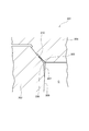
- FIG. 9 is a diagram showing a main part of the foam molding die 201 according to the third embodiment of the present invention.
- FIG. 10 is a diagram showing a main part of a foam molding die 301 according to a modified example of the present invention.
- the nickel-plated portion 205 is provided on the ridge portion 207 formed by two surfaces intersecting at an obtuse angle.
- the nickel-plated portion 205 is provided on the ridge portion formed by a part of the cavity surface 209 and the non-cavity surface 210.
- the present invention can also be applied to the foam molding die 201 having such a shape.
- the nickel-plated portions 205 and 305 may be provided on the fixed mold 202 as shown in FIG. 9, or may be provided on the mobile mold 303 as shown in FIG.
- a nickel-plated portion may be provided at a corner composed of two surfaces other than the cavity surface.
- the nickel-plated portion is provided on the surface forming the cavity because it is possible to prevent the foamed resin raw material from protruding from the cavity at the outer edge of the cavity.
- FIG. 11 is a diagram showing a foam molding die 401 according to a fourth embodiment of the present invention.
- the nickel-plated portion 405 may be provided on the non-cavity surface 410 of the mobile type 403. In this case, it is preferable that the nickel-plated portion 405 is provided at the boundary between the non-cavity surface 410 and the cavity surface 409 so that burrs are less likely to occur in the product.
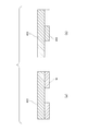
- FIG. 12 is a schematic view showing how the nickel-plated portion 405 is formed.
- the mobile 403 forming the nickel-plated portion 405 is masked so that the portion forming the nickel-plated portion 405 is exposed. Apply M.
- the nickel-plated portion 405 is formed by electroplating, electroless plating, or the like.
- the nickel-plated portion 405 is evenly attached to the flat non-cavity surface 410 of the mobile type 403, and the rectangular nickel-plated portion 405 is formed as shown in the figure. It is formed.
- the masking M is removed as shown in FIG. 12 (b).
- FIG. 13 is a diagram showing how the recess 406 is formed.
- the mobile mold 403 plated with the nickel-plated portion 405 is driven into the fixed mold 402 in the mold clamping direction.
- FIG. 13B shows a state in which the mobile type 403 is struck against the fixed type 402 and the nickel-plated portion 405 is fitted into the fixed type 402.
- the mobile type 403 and the fixed type 402 are separated from the state of (b) in FIG. 13, and the mobile type 403 is hit against the fixed type 402 again.
- the shape of the nickel-plated portion 405 is transferred to the fixed mold 402 and the recess 406 is formed as shown in FIG. 13 (c).
- the nickel-plated part 405 When the mobile type 403 is hit against the fixed type 402, the nickel-plated part 405 also crushes the mobile type 403 by the reaction force received from the fixed type 402. As a result, the recess 411 is also formed in the mobile type 403 in which the nickel-plated portion 405 is plated. As described above, the recess 411 may be provided in the mobile type 403 in which the nickel-plated portion 405 is provided, in addition to the fixed type 402 in which the nickel-plated portion 405 is not provided. Thereby, the sealing property between the mobile type 403 and the fixed type 402 can be further improved.
- the cavities are formed by contact between the nickel-plated portions 205, 305, 405 and the recesses 206, 306, 406, as in the above-described embodiment. Can be sealed with high precision.
- the present invention is not limited to the above-described embodiment, and can be freely modified, improved, and the like as appropriate.
- the material, shape, size, numerical value, form, number, arrangement location, etc. of each component in the above-described embodiment are arbitrary and are not limited as long as the present invention can be achieved.
- the present invention is not limited to this.
- the high hardness metal part is harder than the second type metal, such as iron for the second type and tungsten for the high hardness metal part
- the metal used for the second type and the high hardness metal part is limited to aluminum and nickel. do not have.
- a mold for foam molding in which burrs are less likely to occur in the foam molded product, and a method for manufacturing the foam molded product using the mold.
Landscapes
- Engineering & Computer Science (AREA)
- Mechanical Engineering (AREA)
- Manufacturing & Machinery (AREA)
- Moulds For Moulding Plastics Or The Like (AREA)
Abstract
発泡成形用金型(1)は、第一型(2)と第二型(3)とを有する。型合わせ時には、第一型(2)に設けられた第一型接触部(21)と、第二型(3)に設けられた第二型接触部(31)とが接触して、発泡成形用金型(1)の内部に形成されるキャビティ(C)を封止可能とされている。第一型接触部(21)は第二型(2)よりも硬度の高い高硬度金属部を備えている。第二型接触部(31)には、高硬度金属部(5)における前記第二型接触部に接触する部位に対応する形状の凹部(6)が設けられている。
Description
本発明は、発泡成形用金型および発泡成形品の製造方法に関する。
特許文献1には、発泡成形品の製造に用いるウレタン発泡型が開示されている。
特許文献1の発泡成形においては、キャビティ内を満たした発泡体原料が、その発泡により増大したキャビティ内の圧力により、成形型の分割面のわずかな隙間に侵入してしまう。隙間に入った発泡体原料は、発泡成形体にバリとして残ってしまう。バリの除去は人手による場合も多く、バリが生じてしまうと製造時間やコストの増大につながる。
そこで本発明は、バリが発泡成形品に生じにくい発泡成形用金型およびそれを用いた発泡成形品の製造方法を提供する。
そこで本発明は、バリが発泡成形品に生じにくい発泡成形用金型およびそれを用いた発泡成形品の製造方法を提供する。
本発明の一態様によれば、
金属製の第一型と第二型とを有する、発泡成形に用いられる発泡成形用金型であって、
型合わせ時には、前記第一型に設けられた第一型接触部と、前記第二型に設けられた第二型接触部とが接触することで、前記発泡成形用金型の内部に形成されるキャビティを封止可能とされており、
前記第一型接触部は、前記第二型の金属よりも硬度の高い高硬度金属部で形成され、
前記第二型接触部には、前記高硬度金属部における前記第二型接触部に接触する部位に対応する形状の凹部が設けられている、
発泡成形用金型が提供される。
金属製の第一型と第二型とを有する、発泡成形に用いられる発泡成形用金型であって、
型合わせ時には、前記第一型に設けられた第一型接触部と、前記第二型に設けられた第二型接触部とが接触することで、前記発泡成形用金型の内部に形成されるキャビティを封止可能とされており、
前記第一型接触部は、前記第二型の金属よりも硬度の高い高硬度金属部で形成され、
前記第二型接触部には、前記高硬度金属部における前記第二型接触部に接触する部位に対応する形状の凹部が設けられている、
発泡成形用金型が提供される。
上記した本発明の一態様において、
前記第一型における本体は、キャビティ面と非キャビティ面とで形成される角が面取りされた面取り部を備えており、
前記高硬度金属部は前記面取り部に配置されていてもよい。
前記第一型における本体は、キャビティ面と非キャビティ面とで形成される角が面取りされた面取り部を備えており、
前記高硬度金属部は前記面取り部に配置されていてもよい。
上記した本発明の一態様において、
前記発泡成形用金型の型開きするときの型開き方向に平行な断面において、前記面取り部と前記高硬度金属部との接触長さが0.5mm以上であってもよい。
前記発泡成形用金型の型開きするときの型開き方向に平行な断面において、前記面取り部と前記高硬度金属部との接触長さが0.5mm以上であってもよい。
上記した本発明の一態様において、
前記第一型には、前記高硬度金属部の配設部に前記高硬度金属部に対応する凹部が設けられていてもよい。
前記第一型には、前記高硬度金属部の配設部に前記高硬度金属部に対応する凹部が設けられていてもよい。
上記した本発明の一態様において、
前記第一型及び第二型はアルミニウム製であり、前記高硬度金属部はニッケル製であってもよい。
前記第一型及び第二型はアルミニウム製であり、前記高硬度金属部はニッケル製であってもよい。
本発明の他の態様によれば、
上記した発泡成形用金型を用いた発泡成形品の製造方法であって、
前記高硬度金属部が前記第二型に設けられた前記凹部にはまり込むように前記第一型と前記第二型とを型合わせし、
前記第一型接触部と前記第二型接触部によって封止された前記キャビティ内に発泡樹脂原料を流し込み、前記発泡樹脂原料を発泡させ、硬化させて、前記発泡成形品を得る、発泡成形品の製造方法が提供される。
上記した発泡成形用金型を用いた発泡成形品の製造方法であって、
前記高硬度金属部が前記第二型に設けられた前記凹部にはまり込むように前記第一型と前記第二型とを型合わせし、
前記第一型接触部と前記第二型接触部によって封止された前記キャビティ内に発泡樹脂原料を流し込み、前記発泡樹脂原料を発泡させ、硬化させて、前記発泡成形品を得る、発泡成形品の製造方法が提供される。
本発明によれば、バリが発泡成形品に生じにくい発泡成形用金型およびそれを用いた発泡成形品の製造方法が提供される。
以下、本発明を実施の形態をもとに図面を参照しながら説明する。各図面に示される同一または同等の構成要素、部材、処理には、同一の符号を付するものとし、適宜重複した説明は省略する。また、実施の形態は、発明を限定するものではなく例示であって、実施の形態に記述される全ての特徴やその組合せは、必ずしも発明の本質的なものであるとは限らない。
図1は、本発明の実施形態に係る発泡成形用金型1を示す図である。図1は、型開き方向Aに沿った発泡成形用金型1の断面を示している。本実施形態に係る発泡成形用金型1は、アルミニウム製である。発泡成形用金型1は、発泡ポリウレタンなどの発泡樹脂原料から発泡成形品Rを形成するために用いられる。
図1に示すように本実施形態に係る発泡成形用金型1は、固定型(第一型)2と移動型(第二型)3とを有している。固定型2と移動型3とを型合わせすると、その内部にキャビティCが形成される。固定型2と移動型3とを型合わせする際に互いに接触する部位を接触部と呼ぶ。固定型2は、型合わせ時に移動型3と接触する固定側接触部(第一型接触部)21を有している。移動型3は、型合わせ時に固定型2と接触する移動側接触部(第二型接触部)31を有している。型締め時には、固定側接触部21と移動側接触部31が接触することにより、キャビティCを封止可能とする。固定側接触部21と移動側接触部31は、キャビティCを囲むようにキャビティCの開口に連続するように存在している。
図示した発泡成形用金型1において、蝶番4によって固定型2と移動型3とが接続されている。蝶番4を中心に移動型3が回動することにより、型締めしたり型開きしたりする。図1に示した例においては、固定型2と移動型3の右端に設けられた蝶番4を回転中心にして、移動型3が時計回りに移動することで型開きする。以降の説明において、型開き方向Aとは、型締めされた状態から型開きするときの方向である。図1においては、上下方向が型開き方向Aとなる。
本実施形態においては、図1に示すように、固定型2はニッケルメッキ部5(高硬度金属部の一例)を有している。ニッケルメッキ部5は固定型2に設けられている。ニッケルメッキ部5は、移動型3(第二型)の金属であるアルミニウムよりも硬度の高い部位である。本例では、ニッケルメッキ部5は、ジンケート処理されたアルミニウム製の固定型2におけるキャビティCの開口部位にニッケルをメッキすることにより形成されている。ニッケルメッキ部5は、移動型3に向かって突出した形状とされている。図1に示すように、型合わせ時にニッケルメッキ部5と接触する移動型3の移動側接触部31の少なくとも一部には、ニッケルメッキ部5における固定側接触部21に対応する形状の凹部6が設けられている。なおこのニッケルメッキ部5も、キャビティCを囲むようにキャビティCの開口に線状に存在する固定側接触部21に沿って、キャビティCを囲むようにキャビティCの開口に連続するように存在している。
この凹部6は、凹部6が設けられていない移動型3と固定型2とを型合わせし、この状態で型締め方向(型開き方向Aと反対の方向・図1における下方)に大きな力を移動型3に作用させて形成される。移動型3はアルミニウム製であり、一方で、ニッケルメッキ部5はニッケルで構成されている。アルミニウム製の移動型3のヴィッカース硬度はおよそ50~80Hvであり、ニッケルメッキ部5の硬度は400Hv以上である。つまりアルミニウム製の移動型3はニッケルメッキ部5よりも軟らかい。
型締めした状態で移動型3と固定型2とに型締め方向に大きな力を作用させると、ニッケルメッキ部5が移動型3に食い込み、ニッケルメッキ部5が接触している移動型3の部位が圧し潰されてニッケルメッキ部5の形状が転写され、凹部6が形成される。このため、移動型3に形成された凹部6の形状はニッケルメッキ部5における移動側接触部31に接触する部分の形状に対応しており、型締め時にはニッケルメッキ部5と凹部6とが隙間なく接触するようになる。
なお、凹部6の「ニッケルメッキ部5における移動側接触部31に接触する部分に対応する形状」とは、ニッケルメッキ部5に完全に一致する形状でなくても、ニッケルメッキ部5と組み合わせたときにニッケルメッキ部5と凹部6との間が密着する形状であればよい。
このように本実施形態に係る発泡成形用金型1によれば、型締め時にニッケルメッキ部5は凹部6にはめ込まれ、ニッケルメッキ部5と凹部6との間に隙間が生じにくい。このため、高い精度でキャビティCが密封される。このため、発泡成形時にキャビティC内に充填された発泡樹脂原料が外部に漏れにくく、バリの発生が抑制されている。
また、このような発泡成形用金型1を用いれば、
ニッケルメッキ部5が凹部6にはまり込むように固定型2と移動型3とを型合わせし、
固定側接触部21と移動側接触部31によって封止されたキャビティC内に発泡樹脂原料を流し込み、発泡樹脂原料を発泡させ、硬化させて、発泡成形品を得ることができる。
このような発泡成形品の製造方法によれば、発泡成形品にバリが生じにくく、成形後にバリ取りなどの後工程が不要にできる、あるいは後工程の負荷を軽減することができる。
ニッケルメッキ部5が凹部6にはまり込むように固定型2と移動型3とを型合わせし、
固定側接触部21と移動側接触部31によって封止されたキャビティC内に発泡樹脂原料を流し込み、発泡樹脂原料を発泡させ、硬化させて、発泡成形品を得ることができる。
このような発泡成形品の製造方法によれば、発泡成形品にバリが生じにくく、成形後にバリ取りなどの後工程が不要にできる、あるいは後工程の負荷を軽減することができる。
図2は、ニッケルメッキ部5の拡大図である。図2に示すように、固定型2における本体はキャビティ面9と非キャビティ面10とで形成される角が面取りされた面取り部8を備えており、ニッケルメッキ部5は、この面取り部8に配置されている。図示の例では、キャビティ面9の一部と、これに隣り合う型割り面PLである非キャビティ面10とがなす角に面取り部8が設けられている。この面取り部8のキャビティ面9に対する角度θは1度以上10度以下が好ましい。
キャビティ面9とこれに隣り合う非キャビティ面10とがなす角部にニッケルメッキ部5を設けると、ニッケルのメッキ時に、ニッケルメッキ部5は角部の先端へ行くほどキャビティC内へ突出するように厚く形成されてしまう。ニッケルメッキ部5がこのような形状に形成されてしまうと、キャビティC内にアンダーカットが生じてしまうおそれがある。そこで本実施形態においては、キャビティ面9を面取りすることで、キャビティC内にアンダーカットが生じにくくされている。
図3は、面取り加工をしない状態で形成されたニッケルメッキ部5を示す写真である。図4は、θが4度の面取り加工がされた状態で形成されたニッケルメッキ部5を示す写真である。図5は、θが9度の面取り加工がされた状態で形成されたニッケルメッキ部5を示す写真である。
図3に示したように、面取り加工をしない場合、角に向かうにつれてニッケルメッキ部5がキャビティ面9に直交する方向への突出量が大きくなってしまう。このニッケルメッキ部5がキャビティCに向かって大きく突出していると、キャビティC内にアンダーカットが生じてしまうおそれがある。
図4に示したように、θが4度の面取り加工がされた状態では、面取り加工によって除去された領域をニッケルメッキ部5が埋めている。このため、十分な強度を有する程度にニッケルメッキ部5を厚く形成した場合でも、ニッケルメッキ部5のキャビティCへの突出量が大きくなり過ぎず、キャビティCにアンダーカットが生じにくい。また、面取り加工によって除去された領域の大部分をニッケルメッキ部5が埋めているので、ニッケルメッキ部5がキャビティ面9よりも極端に凹むことがなく、発泡成形品に不良が生じにくい。
図5に示したように、θが9度の面取り加工がされた状態では、面取りされた領域が大きくなっている。ニッケルメッキ部5もキャビティ面9の一部を構成している。ところが、面取り加工の角度θが大きくなりすぎると、面取りして除去した領域をニッケルメッキ部5が埋めきれない事態が生じる。すると、ニッケルメッキ部5がなす面は、キャビティ面9よりも凹んでしまう。このため、キャビティCにより形成する発泡成形品に不良が生じるおそれがある。なお図5に示した状態ではまだ許容範囲であるが、面取り角度θが9度よりも大きい10度を超えると発泡成形品に不良が生じやすい。
このような理由より、キャビティ面9に設けられる面取り加工の角度θは1度以上10度以下とすることが好ましい。キャビティ面9に2度以上8度以下の角度で面取り加工されていることがより好ましい。キャビティ面9に3度以上7度以下の角度で面取り加工されていることがさらに好ましい。
図6は、ニッケルメッキ部5を形成する様子を示した模式図である。図6の(a)に示したように、ニッケルメッキ部5を形成する際には、まずニッケルメッキ部5を形成する固定型2に、ニッケルメッキ部5を形成する箇所が露出するようにマスキングMを施す。この状態で、電界メッキや無電解メッキなどによりニッケルメッキ部5を形成する。なお、このとき理由は不明であるが、固定型2の角に厚くニッケルメッキ部5が付着し、図6の(b)に示したように角が突出した形状にニッケルメッキ部5が形成される。
次に図6の(b)に示したようにニッケルメッキ部5を形成した後にマスキングMを除去する。このようにしてニッケルメッキ部5を形成した後、移動型3を固定型2に型締め方向に打ち付けて、ニッケルメッキ部5の形状を移動型3に転写して凹部6を形成する。
図7は、メッキにより形成した直後のニッケルメッキ部5と、移動型3に凹部6を形成させた後のニッケルメッキ部5とを比較して示す図である。メッキにより形成した直後のニッケルメッキ部5を一点鎖線で、移動型3に凹部6を形成した後のニッケルメッキ部5を実線で示している。図7に示したように、凹部6を形成するために、移動型3を固定型2に型締め方向に打ち付けると、ニッケルメッキ部5が移動型3から受ける反力によって、固定型2におけるアルミニウム部分がニッケルメッキ部5によって塑性変形してしまう。このため、固定型2におけるニッケルメッキ部5の載置面にも凹部11が形成される。このように、凹部11は、ニッケルメッキ部5が設けられない移動型3の他に、ニッケルメッキ部5が設けられる固定型2に設けられてもよい。これにより、固定型2と移動型3との間のシール性をより高めることができる。
なお、上述した方法によりニッケルメッキ部5により凹部6を形成する際には、ニッケルメッキ部5には型締め方向の大きな力が作用する。ニッケルメッキ部5が型締め方向に沿った面にニッケルメッキ部5がそのまま形成されていると、ニッケルメッキ部5と固定型との界面に大きなせん断力が作用してしまい、ニッケルメッキ部5が剥離しやすい。
そこで本発明においては、型締め方向に対して小さな角度をなすキャビティ面9に面取り部8が設けられており、ニッケルメッキ部5に作用する型締め方向の力の一部を面取りした部位で受けている。このため、ニッケルメッキ部5により凹部6を形成する際に、ニッケルメッキ部5に型締め方向の大きな力が作用しても、ニッケルメッキ部5が剥離しにくい。
そこで本発明においては、型締め方向に対して小さな角度をなすキャビティ面9に面取り部8が設けられており、ニッケルメッキ部5に作用する型締め方向の力の一部を面取りした部位で受けている。このため、ニッケルメッキ部5により凹部6を形成する際に、ニッケルメッキ部5に型締め方向の大きな力が作用しても、ニッケルメッキ部5が剥離しにくい。
図2に戻り、ニッケルメッキ部5は、面取り部8に設けられている。発泡成形用金型1の型開きするときの型開き方向Aに平行な断面において、面取り部8とニッケルメッキ部5とが接触している長さを接触長さLと呼ぶ。
この接触長さLは0.5mm以上あれば好ましい。この長さが0.5mm未満では、ニッケルメッキ部5の移動型3に対する接触面積が小さくなりすぎてニッケルメッキ部5と固定型2との密着強度が小さくなってしまう。このため、ニッケルメッキ部5で凹部6を形成する際などにニッケルメッキ部5が固定型2から剥離してしまう。またこの長さは10mm以下が好ましい。10mmより大きいと、ニッケルメッキ部5のキャビティCへの突出量が小さくなり、発泡成形品に不良が生じやすくなってしまう。
このような理由より、接触長さLは0.5mm以上とすることが好ましい。またこの接触長さLは0.5mm以上10mm以下とすることが好ましい。さらにこの接触長さLは3mm以上7mm以下とすることがより好ましい。
<第二実施形態>
なお、ニッケルメッキ部5を設ける部位は図2に示した部位に限られない。図8は、本発明の第二実施形態に係る発泡成形用金型101の要部を示す図である。
なお、ニッケルメッキ部5を設ける部位は図2に示した部位に限られない。図8は、本発明の第二実施形態に係る発泡成形用金型101の要部を示す図である。
図8に示すように、移動型103には、キャビティCから漏れ出した発泡樹脂原料を受け止める逃し空間Bをなす溝部110が設けられている。キャビティCと溝部110とが、移動型103に設けられた稜部103Aと固定型102に設けられた稜部102Aとが突き合せられた箇所で、隔てられている。ニッケルメッキ部105は、移動型103におけるこのキャビティCと溝部110とを隔てる稜部103Aに設けられている。ニッケルメッキ部105は、キャビティ面109の一部と溝部110をなす非キャビティ面111との角に設けられている。このニッケルメッキ部105が接触する固定型102の部位に、凹部106が形成されている。
本実施形態に係る発泡成形用金型101においても、ニッケルメッキ部105と凹部106との接触によってキャビティCを確実に封止することができる。
なお、キャビティCに充填される発泡樹脂原料はニッケルメッキ部105と凹部106との接触箇所からは外部に漏れ出すことはない。キャビティCの開口を囲むようにニッケルメッキ部105が連続して設けられているが、連続するニッケルメッキ部105の一部は、発泡時に発泡樹脂原料をキャビティCから外部へ逃す通路によって断絶している。このような通路を介して発泡樹脂原料は溝部110へ流れ出るようにされている。これにより発泡樹脂原料の発泡時に、キャビティC内の圧力が高まりすぎることが抑制されている。またニッケルメッキ部105と凹部106とによって、意図しない個所から発泡樹脂原料が外部へ漏れ出ることが抑制され、キャビティC内を意図した圧力に保ちやすい。
なお、キャビティCに充填される発泡樹脂原料はニッケルメッキ部105と凹部106との接触箇所からは外部に漏れ出すことはない。キャビティCの開口を囲むようにニッケルメッキ部105が連続して設けられているが、連続するニッケルメッキ部105の一部は、発泡時に発泡樹脂原料をキャビティCから外部へ逃す通路によって断絶している。このような通路を介して発泡樹脂原料は溝部110へ流れ出るようにされている。これにより発泡樹脂原料の発泡時に、キャビティC内の圧力が高まりすぎることが抑制されている。またニッケルメッキ部105と凹部106とによって、意図しない個所から発泡樹脂原料が外部へ漏れ出ることが抑制され、キャビティC内を意図した圧力に保ちやすい。
本実施形態においても、キャビティ面109の一部にニッケルメッキ部105が設けられており、このキャビティ面109の一部に面取り部108が設けられている。これにより、ニッケルメッキ部105のキャビティCへの突出量が抑えられている。
また、本実施形態においては、ニッケルメッキ部105は移動型103に設けられている。ニッケルメッキ部105が移動型103に設けられていても、上記第一実施形態と同様に凹部106とともにキャビティCを高精度に密封できる。
<第三実施形態>
上述した第一実施形態および第二実施形態では、2つの面が90度の角度で交わる稜部にニッケルメッキ部が設けられた発泡成形用金型を説明したが、本発明はこれらの例に限られない。図9は、本発明の第三実施形態に係る発泡成形用金型201の要部を示す図である。図10は、本発明の変形例に係る発泡成形用金型301の要部を示す図である。
上述した第一実施形態および第二実施形態では、2つの面が90度の角度で交わる稜部にニッケルメッキ部が設けられた発泡成形用金型を説明したが、本発明はこれらの例に限られない。図9は、本発明の第三実施形態に係る発泡成形用金型201の要部を示す図である。図10は、本発明の変形例に係る発泡成形用金型301の要部を示す図である。
図9に示したように、ニッケルメッキ部205は鈍角で交わる2つの面のなす稜部207に設けられている。図示した例では、キャビティ面209の一部と、非キャビティ面210とがなす稜部にニッケルメッキ部205が設けられている。このような形状の発泡成形用金型201にも、本発明を適用することができる。
ニッケルメッキ部205,305は、図9に示したように固定型202に設けてもよいし、図10に示したように移動型303に設けてもよい。
ニッケルメッキ部205,305は、図9に示したように固定型202に設けてもよいし、図10に示したように移動型303に設けてもよい。
上述した第一実施形態から第三実施形態では、キャビティ面とこの面と隣り合う任意の面からなる角にニッケルメッキ部が設けられている例を説明したが、本発明はこれに限られない。キャビティ面以外の2つの面からなる角にニッケルメッキ部が設けられていてもよい。もっとも、キャビティをなす面にニッケルメッキ部が設けられていると、キャビティの外縁で発泡樹脂原料がキャビティからはみ出すことを抑制できるので好ましい。
<第四実施形態>
<第四実施形態>
また上述した第一実施形態から第三実施形態では、ニッケルメッキ部をキャビティ面と非キャビティ面とがなす角に設けた例を説明したが、本発明はこれに限られない。図11は、本発明の第四実施形態に係る発泡成形用金型401を示す図である。
図11に示したように、移動型403の非キャビティ面410にニッケルメッキ部405が設けられてもよい。この場合、製品にバリが生じにくくなるように、非キャビティ面410のうちキャビティ面409との境界にニッケルメッキ部405が設けられることが好ましい。
図12は、ニッケルメッキ部405を形成する様子を示した模式図である。図12の(a)に示したように、ニッケルメッキ部405を形成する際には、まずニッケルメッキ部405を形成する移動型403に、ニッケルメッキ部405を形成する箇所が露出するようにマスキングMを施す。この状態で、電界メッキや無電解メッキなどによりニッケルメッキ部405を形成する。なお、このとき図6に示した例とは異なり、移動型403の平面状の非キャビティ面410に均等にニッケルメッキ部405が付着し、図に示したように矩形状のニッケルメッキ部405が形成される。その後、図12の(b)に示したようにマスキングMを除去する。
図13は、凹部406を形成する様子を示す図である。まず図13の(a)に示したように、ニッケルメッキ部405がメッキされた移動型403を固定型402に型締め方向に打ち付ける。図13の(b)は、移動型403を固定型402に打ち付けて、ニッケルメッキ部405を固定型402にめり込ませた様子を示す。図13の(b)の状態から移動型403と固定型402とを離し、再び移動型403を固定型402に打ち付ける。このような打ち付け工程を何度か繰り返すと、図13の(c)に示すようにニッケルメッキ部405の形状が固定型402に転写されて凹部406が形成される。
なお移動型403を固定型402に打ち付ける際、ニッケルメッキ部405が固定型402から受ける反力によって、ニッケルメッキ部405によって移動型403も圧し潰される。これによりニッケルメッキ部405がメッキされた移動型403にも凹部411が形成される。このように、凹部411は、ニッケルメッキ部405が設けられない固定型402の他に、ニッケルメッキ部405が設けられる移動型403にも設けられてもよい。これにより、移動型403と固定型402との間のシール性をより高めることができる。
本実施形態および変形例に係る発泡成形用金型201,301,401においても、上述した実施形態と同様に、ニッケルメッキ部205,305,405と凹部206,306,406との接触によってキャビティを高精度に密封できる。
なお、本発明は、上述した実施形態に限定されず、適宜、変形、改良等が自在である。
その他、上述した実施形態における各構成要素の材質、形状、寸法、数値、形態、数、配置場所等は、本発明を達成できるものであれば任意であり、限定されない。
その他、上述した実施形態における各構成要素の材質、形状、寸法、数値、形態、数、配置場所等は、本発明を達成できるものであれば任意であり、限定されない。
上述した実施形態では、第二型がアルミニウム、高硬度金属部がニッケルである例を説明したが、本発明はこれに限られない。例えば第二型が鉄、高硬度金属部がタングステンなど、高硬度金属部が第二型の金属よりも硬度が高ければ、第二型および高硬度金属部に用いる金属はアルミニウムやニッケルに限られない。
本出願は、2020年1月14日出願の日本特許出願(特願2020-3581)に基づくものであり、その内容はここに参照として取り込まれる。
本発明によれば、バリが発泡成形品に生じにくい発泡成形用金型およびそれを用いた発泡成形品の製造方法が提供される。
1 発泡成形用金型
2 固定型(第一型)
3 移動型(第二型)
4 蝶番
5 ニッケルメッキ部
6 凹部
8 面取り部
9 キャビティ面
10 非キャビティ面
11 凹部
21 固定側接触部
31 移動側接触部
101 発泡成形用金型
102 固定型
103 移動型
105 ニッケルメッキ部
106 凹部
108 面取り部
109 キャビティ面
110 溝部
201 発泡成形用金型
202 固定型
205 ニッケルメッキ部
206 凹部
207 稜部
209 キャビティ面
301 発泡成形用金型
303 移動型
305 ニッケルメッキ部
306 凹部
401 発泡成形用金型
402 固定型
403 移動型
405 ニッケルメッキ部
406 凹部
409 キャビティ面
410 非キャビティ面
411 凹部
A 型開き方向
C キャビティ
M マスキング
L 接触長さ
PL 型割り面
R 発泡成形品
B 逃し空間
Claims (6)
- 金属製の第一型と第二型とを有する、発泡成形に用いられる発泡成形用金型であって、
型合わせ時には、前記第一型に設けられた第一型接触部と、前記第二型に設けられた第二型接触部とが接触することで、前記発泡成形用金型の内部に形成されるキャビティを封止可能とされており、
前記第一型接触部は、前記第二型の金属よりも硬度の高い高硬度金属部で形成され、
前記第二型接触部には、前記高硬度金属部における前記第二型接触部に接触する部位に対応する形状の凹部が設けられている、
発泡成形用金型。 - 前記第一型における本体は、キャビティ面と非キャビティ面とで形成される角が面取りされた面取り部を備えており、
前記高硬度金属部は面取り部に配置されている、請求項1に記載の発泡成形用金型。 - 前記発泡成形用金型の型開きするときの型開き方向に平行な断面において、前記面取り部と前記高硬度金属部との接触長さが0.5mm以上である、請求項2に記載の発泡成形用金型。
- 前記第一型には、前記高硬度金属部の配設部に前記高硬度金属部に対応する凹部が設けられている、請求項1に記載の発泡成形用金型。
- 前記第一型および前記第二型はアルミニウム製であり、前記高硬度金属部はニッケル製である、請求項1に記載の発泡成形用金型。
- 請求項1に記載の発泡成形用金型を用いた発泡成形品の製造方法であって、
前記高硬度金属部が前記第二型に設けられた前記凹部にはまり込むように前記第一型と前記第二型とを型合わせし、
前記第一型接触部と前記第二型接触部によって封止された前記キャビティ内に発泡樹脂原料を流し込み、前記発泡樹脂原料を発泡させ、硬化させて、前記発泡成形品を得る、発泡成形品の製造方法。
Priority Applications (1)
| Application Number | Priority Date | Filing Date | Title |
|---|---|---|---|
| JP2021571190A JPWO2021145315A1 (ja) | 2020-01-14 | 2021-01-12 |
Applications Claiming Priority (2)
| Application Number | Priority Date | Filing Date | Title |
|---|---|---|---|
| JP2020-003581 | 2020-01-14 | ||
| JP2020003581 | 2020-01-14 |
Publications (1)
| Publication Number | Publication Date |
|---|---|
| WO2021145315A1 true WO2021145315A1 (ja) | 2021-07-22 |
Family
ID=76863866
Family Applications (1)
| Application Number | Title | Priority Date | Filing Date |
|---|---|---|---|
| PCT/JP2021/000732 WO2021145315A1 (ja) | 2020-01-14 | 2021-01-12 | 発泡成形用金型および発泡成形品の製造方法 |
Country Status (2)
| Country | Link |
|---|---|
| JP (1) | JPWO2021145315A1 (ja) |
| WO (1) | WO2021145315A1 (ja) |
Citations (4)
| Publication number | Priority date | Publication date | Assignee | Title |
|---|---|---|---|---|
| JPS6377715U (ja) * | 1986-11-11 | 1988-05-23 | ||
| JP2011000731A (ja) * | 2009-06-16 | 2011-01-06 | Bridgestone Corp | 発泡成形用金型 |
| JP2015020326A (ja) * | 2013-07-18 | 2015-02-02 | 日本写真印刷株式会社 | 錐体状突起成形型製造用金型及びその製造方法並びに錐体状突起成形型の製造方法 |
| JP2019084572A (ja) * | 2017-11-08 | 2019-06-06 | トヨタ自動車株式会社 | 金型 |
-
2021
- 2021-01-12 JP JP2021571190A patent/JPWO2021145315A1/ja active Pending
- 2021-01-12 WO PCT/JP2021/000732 patent/WO2021145315A1/ja active Application Filing
Patent Citations (4)
| Publication number | Priority date | Publication date | Assignee | Title |
|---|---|---|---|---|
| JPS6377715U (ja) * | 1986-11-11 | 1988-05-23 | ||
| JP2011000731A (ja) * | 2009-06-16 | 2011-01-06 | Bridgestone Corp | 発泡成形用金型 |
| JP2015020326A (ja) * | 2013-07-18 | 2015-02-02 | 日本写真印刷株式会社 | 錐体状突起成形型製造用金型及びその製造方法並びに錐体状突起成形型の製造方法 |
| JP2019084572A (ja) * | 2017-11-08 | 2019-06-06 | トヨタ自動車株式会社 | 金型 |
Also Published As
| Publication number | Publication date |
|---|---|
| JPWO2021145315A1 (ja) | 2021-07-22 |
Similar Documents
| Publication | Publication Date | Title |
|---|---|---|
| US7426998B2 (en) | Molding die assembly for rubber members and rubber member produced thereby | |
| US20060198921A1 (en) | Structure for preventing resin leak | |
| WO2021145315A1 (ja) | 発泡成形用金型および発泡成形品の製造方法 | |
| JPH0948044A (ja) | 金型内被覆成形用金型および型内被覆方法 | |
| JP2002192571A (ja) | シールリング成形用金型及びシールリングの成形方法 | |
| JPH07186199A (ja) | レジントランスファー成形型 | |
| US8047827B2 (en) | Mold for in-mold coating formation | |
| JP2006035590A (ja) | 成形型の分割面のシール構造及び分割面の形成方法 | |
| JP2002501826A (ja) | 特に洗剤バーを型押するためのダイ及び方法 | |
| JP3485142B2 (ja) | 発泡成形型及びインサートと一体発泡した成形体の製造方法 | |
| JP2000320678A (ja) | ガスケットとその製造方法 | |
| JPH11240026A (ja) | 金属−ゴム複合部材およびその製造方法 | |
| JP2022138298A (ja) | 金型および金型の製造方法 | |
| JPH0147670B2 (ja) | ||
| JP5311616B2 (ja) | 樹脂成形品の成形方法、および樹脂成形品の成形装置 | |
| JP4901507B2 (ja) | 樹脂成形体 | |
| JPH0242048B2 (ja) | ||
| JP3011872B2 (ja) | 発泡成形用基材および発泡成形品の製造方法 | |
| TW201805136A (zh) | 離心成形模及中空圓筒體之製造方法 | |
| JPS58212925A (ja) | 射出成形金型 | |
| JPH05269768A (ja) | 発泡樹脂成形金型のシール構造 | |
| JPH1058460A (ja) | 金 型 | |
| JP2019072870A (ja) | 組立型を有する金型及びその金型による樹脂成形体の製造方法 | |
| JP3588500B2 (ja) | 発泡成形品の製造方法 | |
| JP2001088147A (ja) | 自動車用シートクッションパッドの発泡成形金型 |
Legal Events
| Date | Code | Title | Description |
|---|---|---|---|
| 121 | Ep: the epo has been informed by wipo that ep was designated in this application |
Ref document number: 21741688 Country of ref document: EP Kind code of ref document: A1 |
|
| ENP | Entry into the national phase |
Ref document number: 2021571190 Country of ref document: JP Kind code of ref document: A |
|
| NENP | Non-entry into the national phase |
Ref country code: DE |
|
| 122 | Ep: pct application non-entry in european phase |
Ref document number: 21741688 Country of ref document: EP Kind code of ref document: A1 |