WO2021144942A1 - 遠心送風機及び空気調和装置 - Google Patents
遠心送風機及び空気調和装置 Download PDFInfo
- Publication number
- WO2021144942A1 WO2021144942A1 PCT/JP2020/001407 JP2020001407W WO2021144942A1 WO 2021144942 A1 WO2021144942 A1 WO 2021144942A1 JP 2020001407 W JP2020001407 W JP 2020001407W WO 2021144942 A1 WO2021144942 A1 WO 2021144942A1
- Authority
- WO
- WIPO (PCT)
- Prior art keywords
- impeller
- centrifugal blower
- barrier portion
- bell mouth
- wall
- Prior art date
- Legal status (The legal status is an assumption and is not a legal conclusion. Google has not performed a legal analysis and makes no representation as to the accuracy of the status listed.)
- Ceased
Links
Images










Classifications
-
- F—MECHANICAL ENGINEERING; LIGHTING; HEATING; WEAPONS; BLASTING
- F04—POSITIVE - DISPLACEMENT MACHINES FOR LIQUIDS; PUMPS FOR LIQUIDS OR ELASTIC FLUIDS
- F04D—NON-POSITIVE-DISPLACEMENT PUMPS
- F04D29/00—Details, component parts, or accessories
- F04D29/08—Sealings
- F04D29/16—Sealings between pressure and suction sides
-
- F—MECHANICAL ENGINEERING; LIGHTING; HEATING; WEAPONS; BLASTING
- F04—POSITIVE - DISPLACEMENT MACHINES FOR LIQUIDS; PUMPS FOR LIQUIDS OR ELASTIC FLUIDS
- F04D—NON-POSITIVE-DISPLACEMENT PUMPS
- F04D29/00—Details, component parts, or accessories
- F04D29/40—Casings; Connections of working fluid
- F04D29/42—Casings; Connections of working fluid for radial or helico-centrifugal pumps
- F04D29/44—Fluid-guiding means, e.g. diffusers
Definitions
- the present invention relates to a centrifugal blower having a scroll casing and an air conditioner provided with the centrifugal blower.
- centrifugal blowers have a spiral-shaped scroll casing that gradually expands the air passage and guides it to the discharge port, and an impeller that is housed inside the scroll casing and rotates around the axis.
- Some of the air suction ports of such scroll casings are provided with a bell mouth that guides the air flow to the impeller.
- the impeller has a plurality of blades, a main plate in which the plurality of blades are arranged on the circumference around the rotation axis, and an annular side plate in which the end portions of the plurality of blades on the suction side are connected to each other. I have something to have.
- the airflow flowing out from between adjacent blades due to the rotation of the impeller has a velocity distribution in the axial direction of the rotation axis of the impeller.
- the velocity distribution of the airflow has a bias toward the side plate depending on the environment in which it is used, and a part of the airflow may flow back along the back side of the bell mouth without flowing in the scroll casing. In this way, the airflow leaking from the air flow in the scroll casing and flowing along the back of the bell mouth re-flows into the impeller and hits the blades, generating a loud noise as the wind noise of the blades.
- the present invention is for solving the above-mentioned problems, and is a centrifugal blower and an air conditioner that prevent the airflow flowing out from the impeller from re-inflowing into the impeller and suppress the noise generated by the airflow.
- the purpose is to get.
- the centrifugal blower according to the present invention has a main plate that is rotationally driven, an annular side plate that is arranged so as to face the main plate, one end that is connected to the main plate, and the other end that is connected to the side plate. It has an impeller having a plurality of arranged blades, a peripheral wall formed in a spiral shape, and a side wall having a bell mouth forming a suction port communicating with a space formed by the main plate and the plurality of blades.
- the bell mouth is provided with a scroll casing for accommodating the impeller, and the bell mouth is formed in a ring shape with a tubular bell mouth peripheral wall protruding from the side wall, and an outer peripheral edge forming an outer peripheral edge.
- the portion is continuous with the protruding end of the bell mouth peripheral wall, and the inner peripheral edge forming the inner peripheral edge forms a suction port so that the opening diameter gradually decreases toward the inside of the scroll casing.
- the scroll casing is provided between the peripheral wall of the bell mouth and the inner peripheral edge in the radial direction of the impeller, and is a barrier extending from the side wall toward the impeller side.
- the barrier portion is formed so that the distance between the barrier portion and the side plate is smaller than the distance between the peripheral wall and the side plate and the distance between the bellmouth peripheral wall and the side plate. be.
- the air conditioner according to the present invention includes the above-mentioned centrifugal blower and a heat exchanger arranged at a position facing the discharge port of the centrifugal blower.
- the scroll casing of the centrifugal blower is provided between the peripheral wall of the bell mouth and the inner peripheral edge portion in the radial direction of the impeller, and has a barrier portion extending from the side wall toward the impeller side. be.
- the distance between the barrier portion and the side plate is smaller than the distance between the peripheral wall and the side plate and the distance between the bellmouth peripheral wall and the side plate. Therefore, the airflow flowing out from the impeller is blocked by the barrier portion in the direction of re-flowing into the impeller, and flows along the barrier portion extending in the radial direction of the impeller.
- the present invention can prevent the airflow flowing out from the impeller from re-inflowing into the impeller and suppress the noise generated by the airflow.
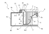
- FIG. FIG. 5 is an external view schematically showing a configuration in which the centrifugal blower according to the first embodiment is viewed in parallel with the rotation axis. It is sectional drawing which shows typically the AA line cross section of the centrifugal blower shown in FIG. It is an enlarged view of the range AR of the centrifugal blower shown in FIG. It is an enlarged view which shows an example of the tip part of the barrier part. It is an enlarged conceptual diagram which shows the 1st example of a barrier part. It is an enlarged conceptual diagram which shows the 2nd example of a barrier part. It is an enlarged conceptual diagram which shows the 3rd example of a barrier part.
- FIG. 1 It is an enlarged conceptual diagram which shows the 4th example of a barrier part. It is a conceptual diagram which shows the flow of the wind in the centrifugal blower which concerns on Embodiment 1.
- FIG. 2 It is a conceptual diagram which shows the flow of the wind in the centrifugal blower which concerns on 1st comparative example.
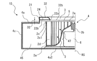
- FIG. 2nd comparative example It is an enlarged view of the centrifugal blower which concerns on Embodiment 2.
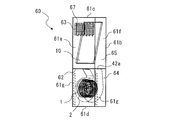
- FIG. It is a front view which conceptually showed an example of the air conditioner which concerns on Embodiment 8. It is a perspective view which conceptually showed an example of the air conditioner which concerns on Embodiment 8.
- FIG. 1 is a perspective view schematically showing the centrifugal blower 1 according to the first embodiment.
- FIG. 2 is an external view schematically showing a configuration in which the centrifugal blower 1 according to the first embodiment is viewed in parallel with the rotation axis RS.
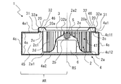
- FIG. 3 is a cross-sectional view schematically showing a cross section taken along line AA of the centrifugal blower 1 shown in FIG. The basic structure of the centrifugal blower 1 will be described with reference to FIGS. 1 to 3.
- the centrifugal blower 1 is, for example, a multi-blade centrifugal blower such as a sirocco fan or a turbo fan, and has an impeller 2 for generating an air flow and a scroll casing 4 for accommodating the impeller 2 inside.
- the centrifugal blower 1 is a single suction type blower in which air is sucked from one side of the scroll casing 4 in the axial direction of the virtual rotating shaft RS of the impeller 2.
- the impeller 2 is a centrifugal fan.
- the impeller 2 is rotationally driven by the drive device 6, and the centrifugal force generated by the rotation forcibly sends air outward in the radial direction.
- the impeller 2 is rotated by the drive device 6 in the rotation direction R indicated by the arrow.
- the drive device 6 is, for example, a motor and applies a driving force to the impeller 2.
- the drive device 6 is arranged inside the scroll casing 4 as shown in FIG. 3, but the drive device 6 is arranged outside the scroll casing 4 and is connected to the main plate 2a of the impeller 2 by a shaft (not shown). May be connected.
- the impeller 2 has a main plate 2a that is rotationally driven by a drive device 6, an annular side plate 2c that is arranged so as to face the main plate 2a, one end that is connected to the main plate 2a, and the other end that is connected to the side plate 2c. , A plurality of blades 2d arranged on the peripheral edge portion 2a1 of the main plate 2a.
- the central portion 2a2 connected to the drive device 6 is directed toward the side plate 2c side, that is, the suction port 2e side in the axial direction of the rotation axis RS with respect to the peripheral edge portion 2a1 connected to the plurality of blades 2d. It has a bulging chevron cross-sectional shape. Then, the drive device 6 is arranged in the recess formed by the inner side surface of the bulging portion of the main plate 2a.
- the shape of the main plate 2a is not limited to that having a chevron cross-sectional shape.
- the main plate 2a may be a member formed in a plate shape such as a disk shape.
- a shaft portion 2b to which the drive device 6 is connected is provided in the central portion 2a2 of the main plate 2a. The main plate 2a is rotationally driven by the drive device 6 via the shaft portion 2b.
- the impeller 2 has an annular side plate 2c attached to an end portion of the plurality of blades 2d opposite to the main plate 2a in the axial direction of the rotating shaft RS.
- the side plate 2c maintains the positional relationship of the tips of the respective blades 2d by connecting the plurality of blades 2d, and reinforces the plurality of blades 2d.
- Each of the plurality of blades 2d has one end connected to the main plate 2a and the other end connected to the side plate 2c, and is arranged in the circumferential direction centered on the virtual rotation axis RS of the main plate 2a.
- Each of the plurality of blades 2d is arranged between the main plate 2a and the side plate 2c.
- the blades 2d are arranged at a certain distance from each other on the peripheral edge portion 2a1 of the main plate 2a.
- the impeller 2 is formed in a tubular shape by a plurality of blades 2d arranged on the main plate 2a. Then, the impeller 2 has a suction port 2e for allowing gas to flow into the space 47 surrounded by the main plate 2a and the plurality of blades 2d on the side plate 2c side opposite to the main plate 2a in the axial direction of the rotating shaft RS. Is formed.
- the impeller 2 is rotationally driven around the rotary shaft RS by being driven by the drive device 6.
- the gas outside the centrifugal blower 1 passes through the suction port 5 formed in the scroll casing 4 and the suction port 2e of the impeller 2, and the main plate 2a and the plurality of blades 2d It is sucked into the enclosed space 47.
- the air sucked into the space 47 surrounded by the main plate 2a and the plurality of blades 2d passes through the space between the adjacent blades 2d and is outside the radial direction of the impeller 2. It is sent to the direction.
- the scroll casing 4 houses the impeller 2 inside and rectifies the air blown out from the impeller 2.
- the scroll casing 4 is made of a foaming material such as Styrofoam.
- the scroll casing 4 is not limited to the one made of a foaming material.
- the scroll casing 4 may be made of a resin material or a metal material.
- the scroll casing 4 has a scroll portion 41 and a discharge portion 42.
- the scroll portion 41 forms an air passage that converts the dynamic pressure of the airflow generated by the impeller 2 into static pressure.
- the scroll portion 41 covers the impeller 2 from the axial direction of the rotating shaft RS, and has a side wall 4a formed with a suction port 5 for taking in air, and a peripheral wall 4c that surrounds the impeller 2 from the radial direction of the rotating shaft RS. And have.
- the scroll portion 41 has a tongue portion 43 that guides the airflow generated by the impeller 2 to the discharge port 42a via the scroll portion 41.
- the radial direction of the rotating shaft RS is a direction perpendicular to the axial direction of the rotating shaft RS.
- the internal space 45 of the scroll portion 41 composed of the peripheral wall 4c and the side wall 4a is a space in which the air blown from the impeller 2 flows along the peripheral wall 4c.
- the side wall 4a is arranged on both sides of the impeller 2 in the axial direction of the rotation axis RS of the impeller 2.
- the scroll casing 4 has a first side wall 4a1 and a second side wall 4a2 as the side wall 4a.
- the first side wall 4a1 is formed along one first end portion 4c11 of the peripheral wall 4c in the axial direction of the rotation axis RS. As shown in FIGS. 1 and 3, the first side wall 4a1 is formed on the side plate 2c side of the impeller 2 on the main plate 2a side and the side plate 2c side in the axial direction of the rotation shaft RS of the impeller 2.
- the first side wall 4a1 is formed with a suction port 5 for taking in air so that air can flow between the impeller 2 and the outside of the scroll casing 4.
- the suction port 5 is formed in a circular shape, and the impeller 2 is arranged so that the center of the suction port 5 and the center of the shaft portion 2b of the impeller 2 substantially coincide with each other.
- the shape of the suction port 5 is not limited to a circular shape, and may be another shape such as an elliptical shape.
- the second side wall 4a2 is formed along the other second end portion 4c12 of the peripheral wall 4c in the axial direction of the rotation axis RS. As shown in FIGS. 1 and 3, the second side wall 4a2 is formed on the main plate 2a side of the impeller 2 on the main plate 2a side and the side plate 2c side in the axial direction of the rotation shaft RS of the impeller 2. The second side wall 4a2 is formed so as to cover the impeller 2 in the axial direction of the rotating shaft RS. The second side wall 4a2 is formed in a plate shape, and the air suction port 5 is not formed on the second side wall 4a2.
- the scroll casing 4 of the centrifugal blower 1 is a single suction type casing having a side wall 4a having a suction port 5 formed on one side of the main plate 2a in the axial direction of the rotating shaft RS of the impeller 2.
- the first side wall 4a1 has a bell mouth 3 that forms a suction port 5 that communicates with a space 47 formed by a main plate 2a and a plurality of blades 2d.
- the suction port 5 provided in the first side wall 4a1 is formed by the bell mouth 3 as shown in FIGS. 1 and 3.
- the bell mouth 3 rectifies the gas sucked into the impeller 2 and causes it to flow into the suction port 2e of the impeller 2.
- the bell mouth 3 is formed so that the opening diameter gradually decreases from the outside to the inside of the scroll casing 4. Due to the configuration of the first side wall 4a1, the air in the vicinity of the suction port 5 smoothly flows along the bell mouth 3 and efficiently flows into the impeller 2 from the suction port 5.
- the bell mouth 3 requires a predetermined length in the radial direction of the impeller 2. If the bell mouth 3 does not have a predetermined length in the radial direction of the impeller 2, the curvature of the bell mouth 3 becomes large, and the airflow flowing along the bell mouth 3 may be separated. Since the bell mouth 3 requires a predetermined length in the radial direction of the impeller 2, the scroll casing 4 forms a space 46 on the back side of the bell mouth 3. This space 46 may become a space through which the airflow flowing out from the impeller 2 passes when it re-flows into the impeller 2.
- the bell mouth 3 protrudes from the first side wall 4a1 and is formed in an annular shape with the bell mouth peripheral wall 31 formed in a tubular shape, and is formed so that the opening diameter gradually decreases toward the inside of the scroll casing 4. It has an air intake unit 32.
- the outer peripheral edge portion 32a forming the edge portion on the outer peripheral side is continuous with the end portion in the protruding direction of the bell mouth peripheral wall 31, and forms the edge portion on the inner peripheral side.
- the inner peripheral edge portion 32b forms the suction port 5.
- the peripheral wall 4c is a wall provided between the side walls 4a facing each other, and constitutes a curved surface in the rotation direction R of the impeller 2.
- the peripheral wall 4c guides the airflow generated by the impeller 2 along the curved wall surface to the discharge port 42a via the scroll portion 41.
- the peripheral wall 4c is arranged parallel to the axial direction of the rotation shaft RS of the impeller 2, for example, and covers the impeller 2.
- the peripheral wall 4c may be inclined with respect to the axial direction of the rotating shaft RS of the impeller 2, and is not limited to the form arranged parallel to the axial direction of the rotating shaft RS.
- the peripheral wall 4c covers the impeller 2 in the radial direction with respect to the rotating shaft RS, and constitutes an inner peripheral surface facing the plurality of blades 2d.
- the peripheral wall 4c faces the air blowing side of the blade 2d of the impeller 2.
- the peripheral wall 4c has a discharge portion 42 and a scroll portion 41 on the side away from the tongue portion 43 along the rotation direction R of the impeller 2 from the winding start portion 41s located at the boundary with the tongue portion 43. It is provided up to the winding end 41b located at the boundary with.
- the winding start portion 41s is an upstream end portion of the airflow generated by the rotation of the impeller 2 on the peripheral wall 4c constituting the curved surface, and the winding end portion 41b is a downstream end of the airflow generated by the rotation of the impeller 2. The end of the side.
- the peripheral wall 4c is formed in a spiral shape in the rotation direction R.
- the spiral shape include a logarithmic spiral, an Archimedes spiral, a spiral shape based on an involute curve, and the like.
- the inner peripheral surface of the peripheral wall 4c constitutes a curved surface that smoothly curves along the circumferential direction of the impeller 2 from the winding start portion 41s, which is the start of spiral winding, to the winding end portion 41b, which is the end of spiral winding.
- the discharge unit 42 forms a discharge port 42a that is generated by the impeller 2 and discharges the airflow that has passed through the scroll unit 41.
- the discharge portion 42 is composed of a hollow pipe having a rectangular cross section orthogonal to the flow direction of the air flowing along the peripheral wall 4c.
- the cross-sectional shape of the discharge portion 42 is not limited to a rectangle.
- the discharge unit 42 forms a flow path that guides the air that is sent out from the impeller 2 and flows in the internal space 45 between the peripheral wall 4c and the impeller 2 so as to be discharged to the outside of the scroll casing 4.
- the discharge portion 42 has an extension plate 42b, a diffuser plate 42c, a first side wall 4a1, and a second side wall 4a2.
- the extension plate 42b is formed so as to extend from the winding end 41b of the peripheral wall 4c, and is a plate-shaped portion integrally formed with the peripheral wall 4c.
- the diffuser plate 42c is a plate-shaped portion that is integrally formed with the tongue portion 43 of the scroll casing 4 and is arranged so as to face the extension plate 42b.
- the diffuser plate 42c is formed at a predetermined angle with the extending plate 42b so that the cross-sectional area of the flow path gradually expands along the air flow direction in the discharge portion 42.
- the extension plate 42b and the diffuser plate 42c are formed between the first side wall 4a1 and the second side wall 4a2. As described above, the discharge portion 42 is formed as a flow path having a rectangular cross section by the extension plate 42b, the diffuser plate 42c, the first side wall 4a1 and the second side wall 4a2.
- the tongue portion 43 is formed between the diffuser plate 42c of the discharge portion 42 and the winding start portion 41s of the peripheral wall 4c.
- the tongue portion 43 is formed with a predetermined radius of curvature, and the peripheral wall 4c is smoothly connected to the diffuser plate 42c via the tongue portion 43.
- the tongue portion 43 suppresses the inflow of air from the winding end to the winding start of the spiral flow path formed in the scroll casing 4.
- the tongue portion 43 is provided in the upstream portion of the ventilation passage, and divides the air flow in the rotation direction R of the impeller 2 and the air flow in the discharge direction from the downstream portion of the ventilation passage toward the discharge port 42a. Has a role. Further, the static pressure of the air flow flowing into the discharge portion 42 increases while passing through the scroll casing 4, and the pressure becomes higher than that in the scroll casing 4. Therefore, the tongue portion 43 has a function of partitioning such a pressure difference.
- FIG. 4 is an enlarged view of the range AR of the centrifugal blower 1 shown in FIG.
- the barrier portion 20 will be described with reference to FIGS. 2 to 4. Note that FIG. 2 conceptually represents the barrier portion 20 which is arranged on the back side of the bell mouth 3 through which the bell mouth 3 is transmitted in order to explain the configuration of the barrier portion 20.
- the scroll casing 4 is provided between the bell mouth peripheral wall 31 and the inner peripheral edge portion 32b in the radial direction of the impeller 2, and extends from the side wall 4a toward the impeller 2 side. It has a barrier portion 20.
- the barrier portion 20 prevents the airflow flowing out from the impeller 2 from flowing in the direction of re-inflow into the impeller 2. That is, the barrier portion 20 prevents the airflow flowing out from the impeller 2 from passing through the space 46.
- the barrier portion 20 is located between the bell mouth peripheral wall 31 and the inner peripheral edge portion 32b in a plan view viewed parallel to the axial direction of the rotation axis RS. That is, the barrier portion 20 is not located closer to the rotation axis RS axis than the inner peripheral edge portion 32b in a plan view viewed parallel to the axis direction of the rotation axis RS.
- the barrier portion 20 is formed in an annular shape in a plan view seen in a direction parallel to the axial direction of the rotation axis RS.
- the barrier portion 20 is not limited to the one formed in an annular shape in a plan view viewed in a direction parallel to the axial direction of the rotation axis RS, and may be formed in an arc shape.
- the distance between the bell mouth peripheral wall 31 and the tip portion 20a forming the inner peripheral edge of the barrier portion 20 in the radial direction of the impeller 2 is defined as the distance DR.
- the length of the distance DR may be constant or may change in the circumferential direction centered on the rotation axis RS. That is, in the circumferential direction centered on the rotation axis RS, the length of the distance DR may always be formed to be the same depending on the measurement point, and the length of the distance DR may be formed to be different depending on the measurement point. You may.
- the same length includes those having exactly the same length and those having substantially the same length.
- the barrier portion 20 is formed in a plate shape in a cross section along the rotation axis RS.
- the barrier portion 20 is not limited to a plate-shaped structure.
- the barrier portion 20 may be formed in a block shape having a thickness in the axial direction of the rotation axis RS in a cross section along the rotation axis RS.
- the barrier portion 20 is formed in a plate shape and is formed so as to extend in a direction perpendicular to the rotation axis RS.
- the extending direction of the barrier portion 20 is not limited to the direction perpendicular to the rotation axis RS, and may be a direction inclined with respect to the direction perpendicular to the rotation axis RS. That is, the barrier portion 20 may be formed in a shape inclined with respect to the direction perpendicular to the rotation axis RS in the cross section along the rotation axis RS. However, the barrier portion 20 does not include a shape formed so as to extend in a direction parallel to the rotation axis RS on the side opposite to the formation side of the bell mouth 3 with respect to the first side wall 4a1.
- the barrier portion 20 is closer to the outer peripheral edge portion 32a than the main plate side end portion 2c1 which is the end portion of the side plate 2c on the main plate 2a side in the axial direction of the rotation axis RS of the main plate 2a. It is provided in. That is, the barrier portion 20 is formed between the position of the main plate side end portion 2c1 and the position of the outer peripheral edge portion 32a in a direction parallel to the axial direction of the rotation axis RS of the main plate 2a.
- the barrier portion 20 faces the side plate 2c in the radial direction of the impeller 2.
- the barrier portion 20 is formed in a plate shape, and the tip portion 20a forming the inner peripheral edge portion of the barrier portion 20 and the side plate 2c are blades.
- the car 2 is formed so as to face each other in the radial direction.
- the distance between the barrier portion 20 and the side plate 2c in the radial direction of the impeller 2 is defined as the distance D1. More specifically, the distance between the tip portion 20a of the barrier portion 20 and the side plate 2c in the radial direction of the impeller 2 is defined as the distance D1.
- the distance D1 is formed so that the distance between the peripheral wall 4c and the side plate 2c is also small. Further, the distance D1 is formed to be smaller than the distance between the bell mouth peripheral wall 31 and the side plate 2c.
- the scroll casing 4 has a barrier portion 20 extending from the bell mouth peripheral wall 31 toward the side plate 2c in a cross section along the rotation axis RS. Then, regardless of the positional relationship between the end portion of the bell mouth peripheral wall 31 on the first side wall 4a1 side and the side plate 2c of the impeller 2, the distance D1 between the tip portion 20a and the side plate 2c is such that the peripheral wall 4c and the side plate 2c It is configured to be smaller than the distance between the bell mouth and the bell mouth peripheral wall 31 and the side plate 2c.
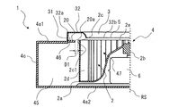
- FIG. 5 is an enlarged view showing an example of the tip portion 20a of the barrier portion 20.
- the tip portion 20a has an inclined portion 20a1 on which the wall surface on the main plate 2a side forms an inclined surface, and is formed so that the thickness becomes thinner toward the tip.
- the tip portion 20a is not limited to the one having the inclined portion 20a1, and may not have the inclined portion 20a1.
- FIG. 6 is an enlarged conceptual diagram showing a first example of the barrier portion 20.
- the barrier portion 20 when the barrier portion 20 is integrally formed with the first side wall 4a1, the barrier portion 20 projects from the first side wall 4a1.
- the barrier portion 20 may have a step portion 20b.
- the step portion 20b protrudes from the first side wall 4a1 and is formed in a cylindrical shape.
- the step portion 20b faces the bell mouth peripheral wall 31 in the radial direction of the impeller 2. Since the barrier portion 20 has the stepped portion 20b, the formation position of the tip portion 20a and the formation position of the first side wall 4a1 are different in the axial direction of the rotation axis RS. That is, a step is formed between the wall surface of the barrier portion 20 that forms the wall of the airflow flow path and the wall surface of the first side wall 4a1 that forms the wall on the airflow flow path side.
- the stepped portion 20b of the barrier portion 20 is in contact with the bell mouth peripheral wall 31, and the barrier portion 20 extends from the bell mouth peripheral wall 31 toward the inner peripheral edge portion 32b in the radial direction of the impeller 2. That is, the outer peripheral edge portion side of the barrier portion 20 is integrally formed with the first side wall 4a1, and the barrier portion 20 is from the bell mouth peripheral wall 31 side to the inner peripheral edge portion 32b side in the radial direction of the impeller 2. Extends towards.
- the stepped portion 20b of the barrier portion 20 may be opposed to the bell mouth peripheral wall 31 and may not be in contact with the bell mouth peripheral wall 31.
- FIG. 7 is an enlarged conceptual diagram showing a second example of the barrier portion 20.
- the barrier portion 20 when the barrier portion 20 is integrally formed with the first side wall 4a1, the barrier portion 20 has an impeller 2 from the first side wall 4a1 in a cross section along the rotation axis RS. It may be formed so as to extend straight toward.
- the wall surface of the barrier portion 20 forming the wall on the airflow flow path side and the wall surface of the first side wall 4a1 forming the wall on the airflow flow path side may form the same plane.
- the thickness of the first side wall 4a1 and the thickness of the barrier portion 20 are shown to be equal, but the thickness of the first side wall 4a1 and the thickness of the barrier portion 20 are shown.
- the thickness may be equal to or different from that of.
- FIG. 8 is an enlarged conceptual diagram showing a third example of the barrier portion 20.
- the barrier portion 20 when the barrier portion 20 is integrally formed with the first side wall 4a1, the barrier portion 20 has an impeller 2 from the first side wall 4a1 in a cross section along the rotation axis RS. It may be formed so as to extend toward.
- the barrier portion 20 may have a slope portion 20c between the first side wall 4a1 and the tip portion 20a.
- the slope portion 20c projects from the first side wall 4a1 to form the side surface shape of the truncated cone.
- the slope portion 20c forms a slope inclined with respect to the axial direction of the rotation axis RS in a cross section along the rotation axis RS.
- the barrier portion 20 has the slope portion 20c, the formation position of the tip portion 20a and the formation position of the first side wall 4a1 are different in the axial direction of the rotation axis RS. That is, a step is formed between the wall surface of the barrier portion 20 that forms the wall of the airflow flow path and the wall surface of the first side wall 4a1 that forms the wall on the airflow flow path side.
- FIG. 9 is an enlarged conceptual diagram showing a fourth example of the barrier portion 20.
- the barrier portion 20 is integrally formed with the first side wall 4a1.
- the barrier portion 20 is not limited to the configuration formed integrally with the first side wall 4a1.
- the barrier portion 20 may be integrally formed with the bell mouth peripheral wall 31 as shown in FIG.
- the barrier portion 20 when the barrier portion 20 is integrally formed with the bell mouth peripheral wall 31, the barrier portion 20 protrudes from the bell mouth peripheral wall 31 and protrudes from the bell mouth peripheral wall 31 in the radial direction of the impeller 2. It extends from the peripheral wall 31 toward the inner peripheral edge portion 32b. That is, the outer peripheral edge side of the barrier portion 20 is integrally formed with the bell mouth peripheral wall 31, and the barrier portion 20 faces the inner peripheral edge portion 32b from the bell mouth peripheral wall 31 in the radial direction of the impeller 2. Is extending.
- the barrier portion 20 formed integrally with the bell mouth peripheral wall 31 may have the step portion 20b or the slope portion 20c described above.
- the barrier portion 20 is made of a foaming material such as Styrofoam.
- the barrier portion 20 is not limited to the one made of a foaming material.
- the barrier portion 20 may be formed of a resin material or a metal material.
- the dynamic pressure of the air blown out from the impeller 2 is converted into static pressure while being guided between the inside of the peripheral wall 4c and the blade 2d by the scroll portion 41, and after passing through the scroll portion 41, it is sent to the discharge portion 42. It is blown out of the scroll casing 4 from the formed discharge port 42a.
- the air blown out from the impeller 2 has a velocity distribution in the axial direction of the rotation shaft RS of the impeller 2, and is biased toward the side plate 2c side of the impeller 2 in the environment in which it is used.
- FIG. 10 is a conceptual diagram showing the flow of wind in the centrifugal blower 1 according to the first embodiment.
- the scroll casing 4 of the centrifugal blower 1 is provided between the bell mouth peripheral wall 31 and the inner peripheral edge portion 32b in the radial direction of the impeller 2, and is provided from the side wall 4a toward the impeller 2 side. It has an extending barrier portion 20.
- the distance D1 between the barrier portion 20 and the side plate 2c is formed to be smaller than the distance between the peripheral wall 4c and the side plate 2c and the distance between the bellmouth peripheral wall 31 and the side plate 2c.
- the airflow FA flowing out of the impeller 2 is blocked from flowing into the impeller 2 by the barrier portion 20 having the configuration, and the airflow FA extends in the radial direction of the impeller 2. It flows along the part 20.
- the airflow FA is the air blown out from the impeller 2, is biased toward the side plate 2c side of the impeller 2, and is blown out from the vicinity of the side plate 2c.
- the airflow FA flowing out of the impeller 2 is suppressed from re-flowing into the impeller 2 by the barrier portion 20. Since the airflow FA flowing out from the impeller 2 is suppressed from re-flowing into the impeller 2, the airflow FA flowing out from the impeller 2 hits the blades 2d and does not generate noise as the wind noise of the blades 2d. .. Therefore, the centrifugal blower 1 having the barrier portion 20 can prevent the airflow FA flowing out from the impeller 2 from re-inflowing into the impeller 2, and can suppress the noise generated by the airflow.
- the airflow FA flowing out from the impeller 2 is blocked from flowing in the direction of re-flowing into the impeller 2, and flows along the barrier portion 20 extending in the radial direction of the impeller 2. Therefore, the airflow FA whose flow is blocked by the barrier portion 20 does not interfere with the other airflow FB and airflow FC flowing out from the impeller 2. Further, no noise is generated due to the interference between the airflow FA whose flow is blocked by the barrier portion 20 and the airflow FB and the airflow FC flowing out from the impeller 2. Therefore, the centrifugal blower 1 having the barrier portion 20 can prevent the airflow flowing out from the impeller 2 from re-inflowing into the impeller 2 and suppress the noise generated by the airflow.
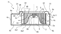
- FIG. 11 is a conceptual diagram showing the flow of wind in the centrifugal blower 1L according to the first comparative example.
- the scroll casing 4L of the centrifugal blower 1L according to the comparative example does not have the barrier portion 20.
- the air blown from the impeller 2 has a velocity distribution in the axial direction of the rotation axis RS of the impeller 2, and is biased toward the side plate 2c side of the impeller 2 in the environment in which it is used.
- a part of the airflow VR flows backward, does not flow in the internal space 45 of the scroll casing 4, passes through the gap space 48 between the side wall 4a and the side plate 2c, passes through the back side of the bell mouth 3, and again.
- FIG. 12 is a conceptual diagram showing the flow of wind in the centrifugal blower 1R according to the second comparative example.
- the scroll casing 4R of the centrifugal blower 1R according to the comparative example does not have a barrier portion 20, and is provided with a backflow prevention plate 120 extending in the axial direction of the rotation shaft RS of the impeller 2.
- the backflow prevention plate 120 extending in the axial direction of the rotating shaft RS of the impeller 2 bends the backflow airflow BR in the axial direction of the rotating shaft RS.
- the backflow airflow BR that is bent in the axial direction of the rotation shaft RS and flows along the backflow prevention plate 120 may hinder the flow of the airflow BA flowing out from the impeller 2. Further, the backflow airflow BR, which is bent in the axial direction of the rotation shaft RS and flows along the backflow prevention plate 120, may interfere with the airflow BA flowing out from the impeller 2 to generate noise.
- the centrifugal blower 1 in the centrifugal blower 1 according to the first embodiment, as shown in FIG. 10, the airflow FA flowing out from the impeller 2 re-flows into the impeller 2 by the barrier portion 20 having the configuration. The directional flow is blocked and flows along the radial barrier portion 20 of the impeller 2. As a result, the centrifugal blower 1 can prevent the airflow FA flowing out from the impeller 2 from re-flowing into the impeller 2 and suppress the noise generated by the airflow. Further, since the airflow FA flowing out from the impeller 2 flows along the barrier portion 20, the barrier portion 20 does not generate an airflow that obstructs the flow of the air blown out from the impeller 2.
- the barrier portion 20 is provided on the outer peripheral edge portion 32a side of the main plate side end portion 2c1 of the side plate 2c in the axial direction of the rotation axis RS of the main plate 2a. In this case, the barrier portion 20 does not obstruct the flow of the airflow blown out from the impeller 2. Therefore, the centrifugal blower 1 having the barrier portion 20 can prevent the airflow flowing out from the impeller 2 from re-inflowing into the impeller 2 and further suppress the noise generated by the airflow.
- the barrier portion 20 faces the side plate 2c in the radial direction of the impeller 2. Therefore, the barrier portion 20 extending from the bell mouth peripheral wall 31 toward the inner peripheral edge portion 32b can reduce the gap space 48 between the side wall 4a and the side plate 2c shown in the first comparative example. Therefore, as shown in FIG. 10, the airflow FA flowing out of the impeller 2 is blocked from flowing into the impeller 2 by the barrier portion 20 having the configuration, and extends in the radial direction of the impeller 2. It flows along the barrier portion 20. As a result, the centrifugal blower 1 can prevent the airflow FA flowing out from the impeller 2 from re-flowing into the impeller 2 and suppress the noise generated by the airflow.
- the tip portion 20a has an inclined portion 20a1 in which the wall surface on the main plate 2a side forms an inclined surface.
- the wall surface on the main plate 2a side is a surface in contact with the air blown from the impeller 2.
- the barrier portion 20 has as much thickness as possible in the axial direction of the rotating shaft RS in order to secure the strength.
- the tip portion 20a may obstruct the flow of air blown out from the impeller 2 depending on the position of the tip portion 20a.
- the tip portion 20a has the inclined portion 20a1
- the air blown out from the impeller 2 tends to flow along the inclined surface of the inclined portion 20a1. Therefore, the barrier portion 20 can easily flow the air blown out from the impeller 2 by having the inclined portion 20a1.
- the barrier portion 20 is formed in an annular shape in a plan view when viewed in the axial direction of the rotation axis RS. Therefore, the centrifugal blower 1 can determine the direction of the discharge port 42a without considering the portion where the flow rate of the air flowing into the suction port 5 is large and the portion where the flow rate is small.
- the barrier portion 20 is integrally formed with the side wall 4a.
- the barrier portion 20 is integrally formed with the bell mouth peripheral wall 31. Since the shield wall portion 20 has the structure of the scroll casing 4, the number of parts can be reduced and the assembly can be facilitated. Further, the scroll casing 4 can reduce costs such as manufacturing cost and material cost because the barrier portion 20 has the above-mentioned configuration.
- the scroll casing 4 is made of a foaming material.
- the weight of the centrifugal blower 1 can be reduced.
- the scroll casing 4 can be easily modeled by having such a configuration. Further, by having the scroll casing 4 having such a configuration, it is possible to reduce costs such as manufacturing cost and material cost.
- the barrier portion 20 is made of a foaming material.
- the scroll casing 4 can reduce the weight of the centrifugal blower 1 because the barrier portion 20 has such a configuration. Further, the scroll casing 4 can be easily modeled because the barrier portion 20 has the above-mentioned structure. Further, the scroll casing 4 can reduce costs such as manufacturing cost and material cost because the barrier portion 20 has the above-mentioned configuration.
- the centrifugal blower 1 further includes a driving device 6 that applies a driving force to the impeller 2.
- the centrifugal blower 1 can prevent the airflow FA flowing out from the impeller 2 from re-inflowing into the impeller 2 and suppress the noise generated by the airflow even if the drive device 6 is contained therein.
- FIG. 13 is an enlarged view of the centrifugal blower 1A according to the second embodiment.
- the centrifugal blower 1A shown in FIG. 13 is an enlarged view of a portion of the range AR of the centrifugal blower 1 shown in FIG.
- the parts having the same configuration as the centrifugal blower 1 of FIGS. 1 to 12 are designated by the same reference numerals, and the description thereof will be omitted.
- the centrifugal blower 1A according to the second embodiment has a different shape of the barrier portion 20 in the centrifugal blower 1 according to the first embodiment. Therefore, in the following description, with reference to FIG. 13, the difference between the barrier portion 21 of the centrifugal blower 1A according to the second embodiment and the barrier portion 20 of the centrifugal blower 1 according to the first embodiment will be mainly. explain.
- the scroll casing 4 has a barrier portion 21 extending from the bell mouth peripheral wall 31 toward the inner peripheral edge portion 32b in the radial direction of the impeller 2.
- the barrier portion 21 prevents the airflow flowing out from the impeller 2 from flowing in the direction of re-inflow into the impeller 2.
- the barrier portion 21 is made of a foaming material such as Styrofoam.
- the barrier portion 21 is not limited to the one made of a foaming material.
- the barrier portion 21 may be formed of a resin material or a metal material.
- the barrier portion 21 may be configured as one member, or may be configured by combining two or more members.
- the barrier portion 21 may be configured as one member by a foam material, a resin material, or a metal material.
- the barrier portion 21 may be composed of the barrier portion 20 and a filling member 21a that fills the space between the barrier portion 20 and the air intake portion 32.
- the filling member 21a is preferably the same member as the barrier portion 21, but may be a different member.
- the filling member 21a is, for example, a foaming material, a resin material, or a metal material.
- the barrier portion 21 is formed in a block shape in a cross section along the rotation axis RS.
- the barrier portion 21 comes into contact with the air intake portion 32 in the axial direction of the rotating shaft RS. Further, as shown in FIG. 13, the barrier portion 21 is formed so as to extend in a direction perpendicular to the rotation axis RS.
- the barrier portion 21 is provided on the outer peripheral edge portion 32a side of the main plate side end portion 2c1 which is the end portion of the side plate 2c on the main plate 2a side in the axial direction of the rotation axis RS of the main plate 2a. ing. That is, the barrier portion 21 is formed between the position of the main plate side end portion 2c1 and the position of the outer peripheral edge portion 32a in a direction parallel to the axial direction of the rotation axis RS of the main plate 2a.
- the barrier portion 21 faces the side plate 2c in the radial direction of the impeller 2.
- a part of the tip portion 20a forming the inner peripheral side edge portion of the barrier portion 21 and the side plate 2c face each other in the radial direction of the impeller 2. It is formed like this.
- the distance between the barrier portion 21 and the side plate 2c in the radial direction of the impeller 2 is defined as the distance D1.
- the distance D1 is formed so that the distance between the peripheral wall 4c and the side plate 2c is also small. Further, the distance D1 is formed to be smaller than the distance between the bell mouth peripheral wall 31 and the side plate 2c.
- the tip portion 20a may have an inclined portion 20a1.
- the scroll casing 4 has a barrier portion 21 extending from the bell mouth peripheral wall 31 toward the side plate 2c in a cross section along the rotation axis RS. Then, regardless of the positional relationship between the end portion of the bell mouth peripheral wall 31 on the first side wall 4a1 side and the side plate 2c of the impeller 2, the distance D1 between the tip portion 20a and the side plate 2c is such that the peripheral wall 4c and the side plate 2c It is configured to be smaller than the distance between the bell mouth and the bell mouth peripheral wall 31 and the side plate 2c.
- the barrier portion 21 comes into contact with the air intake portion 32 in the axial direction of the rotating shaft RS. Therefore, as shown in FIG. 13, the barrier portion 21 is formed in a block shape in a cross section along the rotation axis RS. The barrier portion 21 has a thickness in the axial direction of the rotating shaft RS as compared with the barrier portion 20, so that the strength of the barrier portion 21 can be secured more than that of the barrier portion 20.
- the centrifugal blower 1A has the barrier portion 21 to prevent the airflow flowing out from the impeller 2 from re-inflowing into the impeller 2 as in the case of having the barrier portion 20, and also by the airflow.
- the generated noise can be suppressed.
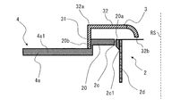
- FIG. 14 is an enlarged view of the centrifugal blower 1B according to the third embodiment.
- the centrifugal blower 1B shown in FIG. 14 is an enlarged view of a portion of the range AR of the centrifugal blower 1 shown in FIG.
- the parts having the same configuration as the centrifugal blower 1 and the like shown in FIGS. 1 to 13 are designated by the same reference numerals, and the description thereof will be omitted.
- the centrifugal blower 1B according to the third embodiment has a different shape of the barrier portion 20 in the centrifugal blower 1 according to the first embodiment. Therefore, in the following description, with reference to FIG. 14, the barrier portion 22 of the centrifugal blower 1B according to the third embodiment is mainly different from the barrier portion 20 of the centrifugal blower 1 according to the first embodiment. explain.
- the scroll casing 4 has a barrier portion 22 extending from the bell mouth peripheral wall 31 toward the inner peripheral edge portion 32b in the radial direction of the impeller 2.
- the barrier portion 22 prevents the airflow flowing out from the impeller 2 from flowing in the direction of re-inflow into the impeller 2.
- the barrier portion 22 is made of the same material as the barrier portion 20.
- the barrier portion 22 is formed in an annular shape in a plan view viewed in a direction parallel to the axial direction of the rotation axis RS.
- the barrier portion 22 is not limited to the one formed in an annular shape in a plan view viewed in a direction parallel to the axial direction of the rotation axis RS, and may be formed in an arc shape.
- the barrier portion 22 is formed in a plate shape in a cross section along the rotation axis RS.
- the barrier portion 22 is not limited to a plate-shaped structure.
- the barrier portion 22 may be formed in a block shape having a thickness in the axial direction of the rotation axis RS.
- the barrier portion 22 may have an inclined portion 20a1.
- the barrier portion 22 is formed in a plate shape and is formed so as to extend in a direction perpendicular to the rotation axis RS.
- the extending direction of the barrier portion 22 is not limited to the direction perpendicular to the rotation axis RS, and may be a direction inclined with respect to the direction perpendicular to the rotation axis RS. That is, the barrier portion 22 may be formed in a shape inclined with respect to the direction perpendicular to the rotation axis RS in the cross section along the rotation axis RS. However, the barrier portion 22 does not include a shape formed so as to extend in a direction parallel to the rotation axis RS.
- the barrier portion 22 is provided on the outer peripheral edge portion 32a side of the main plate side end portion 2c1 which is the end portion of the side plate 2c on the main plate 2a side in the axial direction of the rotation axis RS of the main plate 2a. ing. That is, the barrier portion 22 is formed between the position of the main plate side end portion 2c1 and the position of the outer peripheral edge portion 32a in a direction parallel to the axial direction of the rotation axis RS of the main plate 2a.
- the barrier portion 22 is formed in a plate shape and faces the side plate 2c in the axial direction of the rotating shaft RS.
- the barrier portion 22 is formed in a plate shape, and the tip portion 22a forming the edge portion on the inner peripheral side of the barrier portion 22 and the side plate 2c face each other in the radial direction of the impeller 2.
- the tip portion 22a of the barrier portion 22 is located on the rotation axis RS side of the side plate 2c in the radial direction of the impeller 2.
- the centrifugal blower 1B is viewed in a plan view parallel to the axial direction of the rotating shaft RS, in the order of the inner peripheral edge portion 32b, the tip portion 22a, the side plate 2c, and the bell mouth peripheral wall 31 from the axial side to the outer side of the rotating shaft RS. Have been placed.
- the distance between the barrier portion 22 and the side plate 2c in the direction parallel to the axial direction of the rotation axis RS is defined as the distance D2. More specifically, the distance D2 is defined as the distance between the facing surface 22b of the barrier portion 22 facing the impeller 2 and the side plate 2c in the direction parallel to the axial direction of the rotating shaft RS. The distance D2 is formed so that the distance between the peripheral wall 4c and the side plate 2c is also small. Further, the distance D2 is formed to be smaller than the distance between the bell mouth peripheral wall 31 and the side plate 2c.
- the scroll casing 4 has a barrier portion 22 extending from the bell mouth peripheral wall 31 toward the inner peripheral edge portion 32b in a cross section along the rotation axis RS. Then, regardless of the positional relationship between the end portion of the bell mouth peripheral wall 31 on the first side wall 4a1 side and the side plate 2c of the impeller 2, the distance D2 between the facing surface 22b of the barrier portion 22 and the side plate 2c is determined. It is smaller than the distance between the peripheral wall 4c and the side plate 2c and the distance between the bellmouth peripheral wall 31 and the side plate 2c.
- the scroll casing 4 of the centrifugal blower 1B has a barrier portion 22.
- the barrier portion 22 faces the side plate 2c in the axial direction of the rotating shaft RS.
- the distance D2 between the barrier portion 22 and the side plate 2c is formed to be smaller than the distance between the peripheral wall 4c and the side plate 2c and the distance between the bellmouth peripheral wall 31 and the side plate 2c.
- the centrifugal blower 1B can prevent the air blown out from the impeller 2 from flowing in the direction of re-inflow into the impeller 2. Therefore, since the airflow flowing out from the impeller 2 is suppressed from re-flowing into the impeller 2, the airflow flowing out from the impeller 2 hits the blades 2d and does not generate noise as a wind noise of the blades 2d. .. Therefore, the centrifugal blower 1B having the barrier portion 22 can prevent the airflow flowing out from the impeller 2 from re-inflowing into the impeller 2 and suppress the noise generated by the airflow.
- the centrifugal blower 1B can prevent the airflow flowing out from the impeller 2 from re-flowing into the impeller 2 and suppress the noise generated by the airflow.
- FIG. 15 is an enlarged view of the centrifugal blower 1C according to the fourth embodiment.
- the centrifugal blower 1C shown in FIG. 15 is an enlarged view of a portion of the range AR of the centrifugal blower 1 shown in FIG.
- the parts having the same configuration as the centrifugal blower 1 and the like shown in FIGS. 1 to 14 are designated by the same reference numerals, and the description thereof will be omitted.
- the centrifugal blower 1C according to the fourth embodiment has a different shape of the barrier portion 22 in the centrifugal blower 1B according to the third embodiment. Therefore, in the following description, with reference to FIG. 15, the barrier portion 23 of the centrifugal blower 1C according to the fourth embodiment is mainly different from the barrier portion 22 of the centrifugal blower 1B according to the third embodiment. explain.
- the scroll casing 4 has a barrier portion 23 extending from the bell mouth peripheral wall 31 toward the inner peripheral edge portion 32b in the radial direction of the impeller 2.
- the barrier portion 23 prevents the airflow flowing out from the impeller 2 from flowing in the direction of re-inflow into the impeller 2.
- the barrier portion 23 is made of a foaming material such as Styrofoam.
- the barrier portion 23 is not limited to the one made of a foaming material.
- the barrier portion 23 may be formed of a resin material or a metal material.
- the barrier portion 23 may be configured as one member, or may be configured by combining two or more members.
- the barrier portion 23 may be configured as one member by a foam material, a resin material, or a metal material.
- the barrier portion 23 may be composed of the barrier portion 22 and a filling member 23a that fills the space between the barrier portion 22 and the air intake portion 32.
- the filling member 23a is preferably the same member as the barrier portion 22, but may be a different member.
- the filling member 23a is, for example, a foaming material, a resin material, or a metal material.
- the barrier portion 23 is formed in a block shape in a cross section along the rotation axis RS.
- the barrier portion 23 comes into contact with the air intake portion 32 in the axial direction of the rotating shaft RS.
- the barrier portion 23 is formed so as to extend in a direction perpendicular to the rotation axis RS.
- the tip portion 22a may have an inclined portion 20a1.
- the barrier portion 23 is provided on the outer peripheral edge portion 32a side of the main plate side end portion 2c1 which is the end portion of the side plate 2c on the main plate 2a side in the axial direction of the rotation axis RS of the main plate 2a. ing. That is, the barrier portion 23 is formed between the position of the main plate side end portion 2c1 and the position of the outer peripheral edge portion 32a in a direction parallel to the axial direction of the rotation axis RS of the main plate 2a.
- the distance between the barrier portion 23 and the side plate 2c in the direction parallel to the axial direction of the rotation axis RS is defined as the distance D2. More specifically, the distance D2 is defined as the distance between the facing surface 22b of the barrier portion 23 facing the impeller 2 and the side plate 2c in the direction parallel to the axial direction of the rotating shaft RS. The distance D2 is formed so that the distance between the peripheral wall 4c and the side plate 2c is also small. Further, the distance D2 is formed to be smaller than the distance between the bell mouth peripheral wall 31 and the side plate 2c.
- the scroll casing 4 has a barrier portion 23 extending from the bell mouth peripheral wall 31 toward the inner peripheral edge portion 32b in a cross section along the rotation axis RS. Then, regardless of the positional relationship between the end portion of the bell mouth peripheral wall 31 on the first side wall 4a1 side and the side plate 2c of the impeller 2, the distance D2 between the facing surface 22b of the barrier portion 23 and the side plate 2c is determined. It is smaller than the distance between the peripheral wall 4c and the side plate 2c and the distance between the bellmouth peripheral wall 31 and the side plate 2c.
- the barrier portion 23 comes into contact with the air intake portion 32 in the axial direction of the rotating shaft RS. Therefore, as shown in FIG. 15, the barrier portion 23 is formed in a block shape in a cross section along the rotation axis RS. The barrier portion 23 has a thickness in the axial direction of the rotating shaft RS as compared with the barrier portion 22, so that the strength of the barrier portion 23 can be secured more than that of the barrier portion 22.
- the centrifugal blower 1C prevents the airflow flowing out from the impeller 2 from re-inflowing into the impeller 2 as in the case of having the barrier portion 22, and also by the airflow.
- the generated noise can be suppressed.
- FIG. 16 is an enlarged view of the centrifugal blower 1D according to the fifth embodiment.
- the centrifugal blower 1D shown in FIG. 16 is an enlarged view of a portion of the range AR of the centrifugal blower 1 shown in FIG.
- the parts having the same configuration as the centrifugal blower 1 and the like shown in FIGS. 1 to 15 are designated by the same reference numerals, and the description thereof will be omitted.
- the centrifugal blower 1D according to the fifth embodiment has a different shape of the barrier portion 22 in the centrifugal blower 1B according to the third embodiment. Therefore, in the following description, with reference to FIG. 16, the difference between the barrier portion 24 of the centrifugal blower 1D according to the fifth embodiment and the barrier portion 22 of the centrifugal blower 1B according to the third embodiment will be mainly. explain.
- the scroll casing 4 has a barrier portion 24 extending from the bell mouth peripheral wall 31 toward the inner peripheral edge portion 32b in the radial direction of the impeller 2.
- the barrier portion 24 prevents the airflow flowing out from the impeller 2 from flowing in the direction of re-inflow into the impeller 2.
- the barrier portion 24 is formed in a plate shape, and the tip portion 22a of the barrier portion 24 comes into contact with the air intake portion 32 in the radial direction of the impeller 2.
- the distance between the barrier portion 24 and the side plate 2c in the direction parallel to the axial direction of the rotation axis RS is defined as the distance D2. More specifically, the distance D2 is defined as the distance between the facing surface 22b of the barrier portion 24 facing the impeller 2 and the side plate 2c in the direction parallel to the axial direction of the rotating shaft RS. The distance D2 is formed so that the distance between the peripheral wall 4c and the side plate 2c is also small. Further, the distance D2 is formed to be smaller than the distance between the bell mouth peripheral wall 31 and the side plate 2c.
- the scroll casing 4 has a barrier portion 24 extending from the bell mouth peripheral wall 31 toward the inner peripheral edge portion 32b in a cross section along the rotation axis RS. Then, regardless of the positional relationship between the end portion of the bell mouth peripheral wall 31 on the first side wall 4a1 side and the side plate 2c of the impeller 2, the distance D2 between the facing surface 22b of the barrier portion 24 and the side plate 2c is determined. It is smaller than the distance between the peripheral wall 4c and the side plate 2c and the distance between the bellmouth peripheral wall 31 and the side plate 2c.
- the barrier portion 24 comes into contact with the air intake portion 32 in the radial direction of the impeller 2. Therefore, the barrier portion 24 can secure strength more than the barrier portion 22 because the contact position of the barrier portion 24 increases as compared with the barrier portion 22.
- the centrifugal blower 1D prevents the airflow flowing out from the impeller 2 from re-inflowing into the impeller 2 as in the case of having the barrier portion 22, and also by the airflow.
- the generated noise can be suppressed.
- FIG. 17 is an enlarged view of the centrifugal blower 1E according to the sixth embodiment.
- the centrifugal blower 1E shown in FIG. 17 is an enlarged view of a portion of the range AR of the centrifugal blower 1 shown in FIG.
- the parts having the same configuration as the centrifugal blower 1 and the like shown in FIGS. 1 to 16 are designated by the same reference numerals, and the description thereof will be omitted.
- the centrifugal blower 1E according to the fifth embodiment has a different shape of the barrier portion 22 in the centrifugal blower 1B according to the third embodiment. Therefore, in the following description, using FIG. 17, the barrier portion 25 of the centrifugal blower 1E according to the sixth embodiment will be mainly different from the barrier portion 22 of the centrifugal blower 1B according to the third embodiment. explain.
- the scroll casing 4 has a barrier portion 25 extending from the bell mouth peripheral wall 31 toward the inner peripheral edge portion 32b in the radial direction of the impeller 2.
- the barrier portion 25 prevents the airflow flowing out from the impeller 2 from flowing in the direction of re-inflow into the impeller 2.
- the barrier portion 25 is made of a foaming material such as Styrofoam.
- the barrier portion 25 is not limited to the one made of a foaming material.
- the barrier portion 25 may be formed of a resin material or a metal material.
- the barrier portion 25 may be configured as one member, or may be configured by combining two or more members.
- the barrier portion 25 may be configured as one member by a foam material, a resin material, or a metal material.
- the barrier portion 25 may be composed of the barrier portion 22 and a filling member 25a that fills the space between the barrier portion 22 and the air intake portion 32.
- the filling member 25a is preferably the same member as the barrier portion 22, but may be a different member.
- the filling member 25a is, for example, a foaming material, a resin material, or a metal material.
- the barrier portion 25 is formed in a block shape in a cross section along the rotation axis RS.
- the barrier portion 25 comes into contact with the air intake portion 32 in the axial direction of the rotating shaft RS.
- the barrier portion 25 is formed so as to extend in a direction perpendicular to the rotation axis RS.
- the tip portion 22a of the barrier portion 25 comes into contact with the air intake portion 32 in the radial direction of the impeller 2.
- the distance between the barrier portion 25 and the side plate 2c in the direction parallel to the axial direction of the rotation axis RS is defined as the distance D2. More specifically, the distance D2 is defined as the distance between the facing surface 22b of the barrier portion 25 facing the impeller 2 and the side plate 2c in a direction parallel to the axial direction of the rotating shaft RS. The distance D2 is formed so that the distance between the peripheral wall 4c and the side plate 2c is also small. Further, the distance D2 is formed to be smaller than the distance between the bell mouth peripheral wall 31 and the side plate 2c.
- the scroll casing 4 has a barrier portion 25 extending from the bell mouth peripheral wall 31 toward the inner peripheral edge portion 32b in a cross section along the rotation axis RS.
- the barrier portion 25 fills the space formed by the bell mouth 3 on the side facing the impeller 2. Then, regardless of the positional relationship between the end portion of the bell mouth peripheral wall 31 on the first side wall 4a1 side and the side plate 2c of the impeller 2, the distance D2 between the facing surface 22b of the barrier portion 25 and the side plate 2c is determined. It is smaller than the distance between the peripheral wall 4c and the side plate 2c and the distance between the bellmouth peripheral wall 31 and the side plate 2c.
- the barrier portion 25 comes into contact with the air intake portion 32 in the axial direction of the rotating shaft RS. Therefore, as shown in FIG. 17, the barrier portion 25 is formed in a block shape in a cross section along the rotation axis RS. The barrier portion 25 has a thickness in the axial direction of the rotating shaft RS as compared with the barrier portion 23, so that the strength of the barrier portion 25 can be secured more than that of the barrier portion 23.
- the centrifugal blower 1E has the barrier portion 25 to prevent the airflow flowing out from the impeller 2 from re-inflowing into the impeller 2 as in the case of having the barrier portion 23, and also by the airflow. The generated noise can be suppressed.
- FIG. 18 is a schematic cross-sectional view of the centrifugal blower 1F according to the seventh embodiment.
- FIG. 18 is a conceptual representation of the cross section of the scroll casing 4.
- the parts having the same configuration as the centrifugal blower 1 and the like shown in FIGS. 1 to 17 are designated by the same reference numerals, and the description thereof will be omitted.
- the centrifugal blower 1 and the like according to the first embodiment is a single suction type blower in which air is sucked from one side of the scroll casing 4, whereas the centrifugal blower 1F and the like according to the seventh embodiment are both sides of the scroll casing 4. It is a double suction type blower that sucks air from.
- the centrifugal blower 1F is a double suction type blower in which air is sucked from both sides of the scroll casing 4 in the axial direction of the virtual rotating shaft RS of the impeller 2F.
- the centrifugal blower 1F has an impeller 2 for generating an air flow and a scroll casing 4 for accommodating the impeller 2 inside.
- the impeller 2 has a disk-shaped main plate 2a, an annular side plate 2c arranged to face the main plate 2a, one end connected to the main plate 2a, and the other end connected to the side plate 2c. It has a plurality of blades 2d arranged on the peripheral edge portion 2a1 of the main plate 2a.
- the main plate 2a may have a plate shape, and may have a shape other than a disk shape, such as a polygonal shape.
- the main plate 2a is not limited to one composed of one plate-shaped member, and may be configured by integrally fixing a plurality of plate-shaped members.
- the plurality of blades 2d are provided on both sides of the main plate 2a in the axial direction of the rotating shaft RS.
- the side plates 2c are provided on both sides of the main plate 2a in the axial direction of the rotating shaft RS.
- the impeller 2 is formed in a tubular shape by a plurality of blades 2d arranged on the main plate 2a. Then, the impeller 2 has a suction port 2e for allowing gas to flow into the space 47 surrounded by the main plate 2a and the plurality of blades 2d on the side plate 2c side opposite to the main plate 2a in the axial direction of the rotating shaft RS. Is formed.
- the impeller 2 has blades 2d and side plates 2c arranged on both sides of a plate surface constituting the main plate 2a, and suction ports 2e of the impeller 2 are formed on both sides of the plate surface constituting the main plate 2a.
- the scroll casing 4 houses the impeller 2F for the centrifugal blower 1F inside, and rectifies the air blown out from the impeller 2F.
- the scroll casing 4 has a scroll portion 41 and a discharge portion 42.
- the scroll portion 41 forms an air passage that converts the dynamic pressure of the air flow generated by the impeller 2F into static pressure.
- the scroll portion 41 has a side wall 4a and a peripheral wall 4c.
- the side walls 4a are arranged on both sides of the impeller 2F in the axial direction of the rotating shaft RS of the impeller 2F.
- a suction port 5 is formed on the side wall 4a of the scroll casing 4 so that air can flow between the impeller 2F and the outside of the scroll casing 4.
- the centrifugal blower 1F has two side walls 4a in the scroll casing 4.
- the two side walls 4a are formed so as to face each other via the peripheral wall 4c. More specifically, as shown in FIG. 18, the scroll casing 4 has a first side wall 4a1 and a second side wall 4a21 as the side wall 4a.
- the first side wall 4a1 is formed along one first end portion 4c11 of the peripheral wall 4c in the axial direction of the rotation axis RS.
- the first side wall 4a1 is formed with a suction port 5 for taking in air so that air can flow between the impeller 2 and the outside of the scroll casing 4.
- the second side wall 4a21 is formed along the other second end portion 4c12 of the peripheral wall 4c in the axial direction of the rotation axis RS.
- the second side wall 4a21 is formed with a suction port 5 for taking in air so that air can flow between the impeller 2 and the outside of the scroll casing 4.
- the scroll casing 4 of the centrifugal blower 1F is a double suction type casing having side walls 4a having suction ports 5 formed on both sides of the main plate 2a in the axial direction of the rotation shaft RS of the impeller 2.
- the first side wall 4a1 has a bell mouth 3 that forms a suction port 5 that communicates with a space 47 formed by a main plate 2a and a plurality of blades 2d. As shown in FIG. 18, the suction port 5 provided in the first side wall 4a1 is formed by the bell mouth 3.
- the second side wall 4a21 has a bell mouth 3 that forms a suction port 5 that communicates with the space 47 formed by the main plate 2a and the plurality of blades 2d.
- the suction port 5 provided on the second side wall 4a21 is formed by the bell mouth 3 as shown in FIG.
- the scroll casing 4 has barrier portions 20 on both sides of the main plate 2a in the axial direction of the rotating shaft RS. That is, the barrier portion 20 has a first barrier portion 27 arranged on the first side wall 4a1 side and a second barrier portion 28 arranged on the second side wall 4a21 side.
- FIG. 19 is a front view conceptually showing an example of the air conditioner 60 according to the eighth embodiment.
- FIG. 20 is a perspective view conceptually showing an example of the air conditioner 60 according to the eighth embodiment. Note that FIGS. 19 and 20 show the internal configuration through the housing 61 in order to explain the internal configuration of the air conditioner 60. Further, parts having the same configuration as the centrifugal blower 1 and the like shown in FIGS. 1 to 18 are designated by the same reference numerals, and the description thereof will be omitted.
- the air conditioner 60 according to the eighth embodiment includes one or more of the centrifugal blowers 1 to 1F, a heat exchanger 10 arranged at a position facing the discharge port 42a of the centrifugal blower 1 and the like, and a centrifuge.
- a housing 61 for accommodating the blower 1 and the heat exchanger 10 is provided.
- centrifugal blower 1 it is assumed to be any one of the centrifugal blower 1 to the centrifugal blower 1F.
- the air conditioner 60 according to the eighth embodiment is a floor-standing type air conditioner 60, but the air conditioner 60 is not limited to the floor-standing type.
- the air conditioner 60 may be a ceiling-mounted air conditioner 60 or a wall-mounted air conditioner 60.
- the housing 61 has a front surface portion 61a, a back surface portion 61b, a top surface portion 61c, a bottom surface portion 61d, a left side surface portion 61e, and a right side surface portion 61f, and is formed in a rectangular parallelepiped shape.
- the shape of the housing 61 is not limited to a rectangular parallelepiped shape, and other shapes such as a cylindrical shape, a prismatic shape, a conical shape, a shape having a plurality of corners, and a shape having a plurality of curved surfaces. It may be.
- a suction port 61g for allowing air to flow into the housing 61 is formed on either one or both of the left side surface portion 61e and the right side surface portion 61f.
- the suction port 61g is, for example, a long opening that is long in the vertical direction.
- the suction port 61g may be formed at a position perpendicular to the axial direction of the rotation axis RS of the centrifugal blower 1, and for example, the suction port 61g may be formed on the front surface portion 61a or the back surface portion 61b.
- the suction port 61g shown in FIG. 20 is an example, and the position, size, shape, and the like of the suction port 61g are not limited to the configuration of FIG. 20.
- a filter for removing dust in the air may be arranged at the suction port 61 g.
- an outlet 63 is formed in which the air that has passed through the heat exchanger 10 and has undergone heat exchange flows out.
- the air outlet 63 is, for example, a rectangular opening.
- the outlet 63 is provided with a plurality of vanes 67 for controlling the wind direction.
- the vane 67 is configured so that the wind direction can be adjusted in the vertical direction and the horizontal direction.
- a first space 64 in which the centrifugal blower 1 is arranged and a second space 65 in which the heat exchanger 10 is arranged are formed inside the housing 61.
- the first space 64 and the second space 65 are separated by a partition plate 62.
- the centrifugal blower 1 is attached to a partition plate 62.
- the first space 64 is a space that communicates with the outside of the housing 61 via the suction port 61 g, and is a space on the suction side of the centrifugal blower 1.
- the second space 65 is a space that communicates with the outside of the housing 61 via the air outlet 63, and is a space on the blowout side of the centrifugal blower 1.
- the first space 64 and the second space 65 communicate with each other via the centrifugal blower 1.
- the impeller 2 of the centrifugal blower 1 forms a flow of air that is sucked into the housing 61 from the suction port 61 g and blown out from the air outlet 63 into the air-conditioned space.
- the heat exchanger 10 is arranged at a position facing the discharge port 42a of the centrifugal blower 1, and is arranged on the air passage of the air discharged by the centrifugal blower 1 in the second space 65 of the housing 61.
- the heat exchanger 10 adjusts the temperature of the air that is sucked into the housing 61 from the suction port 61 g and blown out from the air outlet 63 into the air-conditioned space.
- a heat exchanger 10 having a known structure can be applied as the heat exchanger 10.
- the air conditioner 60 according to the eighth embodiment includes the centrifugal blower 1 and the like according to the first embodiment, the same effect as that of the centrifugal blower 1 and the like according to the first embodiment can be obtained. Therefore, the air conditioner 60 can suppress noise generated by the air flow in the centrifugal blower 1, for example.
- each of the above embodiments 1 to 8 can be implemented in combination with each other. Further, the configuration shown in the above embodiment is an example, and can be combined with another known technique, and a part of the configuration is omitted or changed without departing from the gist. It is also possible.
Landscapes
- Engineering & Computer Science (AREA)
- Mechanical Engineering (AREA)
- General Engineering & Computer Science (AREA)
- Structures Of Non-Positive Displacement Pumps (AREA)
- Air-Conditioning Room Units, And Self-Contained Units In General (AREA)
Priority Applications (4)
| Application Number | Priority Date | Filing Date | Title |
|---|---|---|---|
| PCT/JP2020/001407 WO2021144942A1 (ja) | 2020-01-17 | 2020-01-17 | 遠心送風機及び空気調和装置 |
| CN202080092656.4A CN114930034B (zh) | 2020-01-17 | 2020-01-17 | 离心送风机及空气调节装置 |
| JP2021570587A JP7308985B2 (ja) | 2020-01-17 | 2020-01-17 | 遠心送風機及び空気調和装置 |
| TW109117981A TWI801735B (zh) | 2020-01-17 | 2020-05-29 | 離心風扇以及空調裝置 |
Applications Claiming Priority (1)
| Application Number | Priority Date | Filing Date | Title |
|---|---|---|---|
| PCT/JP2020/001407 WO2021144942A1 (ja) | 2020-01-17 | 2020-01-17 | 遠心送風機及び空気調和装置 |
Publications (1)
| Publication Number | Publication Date |
|---|---|
| WO2021144942A1 true WO2021144942A1 (ja) | 2021-07-22 |
Family
ID=76864078
Family Applications (1)
| Application Number | Title | Priority Date | Filing Date |
|---|---|---|---|
| PCT/JP2020/001407 Ceased WO2021144942A1 (ja) | 2020-01-17 | 2020-01-17 | 遠心送風機及び空気調和装置 |
Country Status (4)
| Country | Link |
|---|---|
| JP (1) | JP7308985B2 (https=) |
| CN (1) | CN114930034B (https=) |
| TW (1) | TWI801735B (https=) |
| WO (1) | WO2021144942A1 (https=) |
Cited By (3)
| Publication number | Priority date | Publication date | Assignee | Title |
|---|---|---|---|---|
| CN115468223A (zh) * | 2022-08-18 | 2022-12-13 | 青岛海信日立空调系统有限公司 | 一种离心风机及风管送风式空调机组室内机 |
| WO2023199406A1 (ja) * | 2022-04-12 | 2023-10-19 | 三菱電機株式会社 | 遠心送風機 |
| WO2024037083A1 (zh) * | 2022-08-18 | 2024-02-22 | 青岛海信日立空调系统有限公司 | 空调器、离心风机以及空调室内机 |
Families Citing this family (2)
| Publication number | Priority date | Publication date | Assignee | Title |
|---|---|---|---|---|
| DE102020216155A1 (de) * | 2020-12-17 | 2022-06-23 | Ziehl-Abegg Se | Ventilator und Spiralgehäuse für einen Ventilator |
| TWI864823B (zh) * | 2023-06-15 | 2024-12-01 | 英業達股份有限公司 | 離心式風扇 |
Citations (5)
| Publication number | Priority date | Publication date | Assignee | Title |
|---|---|---|---|---|
| JPH0893695A (ja) * | 1994-09-22 | 1996-04-09 | Daikin Ind Ltd | ファンケーシング |
| JP2011247098A (ja) * | 2010-05-24 | 2011-12-08 | Sanyo Electric Co Ltd | 電動送風機 |
| JP2013124602A (ja) * | 2011-12-15 | 2013-06-24 | Nippon Densan Corp | 遠心ファン装置 |
| JP2014181601A (ja) * | 2013-03-19 | 2014-09-29 | Panasonic Corp | 送風装置 |
| WO2018116498A1 (ja) * | 2016-12-20 | 2018-06-28 | 三菱電機株式会社 | 多翼送風機 |
Family Cites Families (14)
| Publication number | Priority date | Publication date | Assignee | Title |
|---|---|---|---|---|
| JP3700217B2 (ja) * | 1995-10-31 | 2005-09-28 | 株式会社デンソー | 遠心式送風機 |
| JP3638355B2 (ja) * | 1995-11-15 | 2005-04-13 | 三菱電機株式会社 | 空気調和機の室外機 |
| JP4185654B2 (ja) * | 2000-08-04 | 2008-11-26 | カルソニックカンセイ株式会社 | 遠心式の多翼送風機 |
| US7244099B2 (en) * | 2003-05-01 | 2007-07-17 | Daikin Industries, Ltd. | Multi-vane centrifugal fan |
| JP3698150B2 (ja) * | 2003-05-09 | 2005-09-21 | ダイキン工業株式会社 | 遠心送風機 |
| JP2006029164A (ja) | 2004-07-14 | 2006-02-02 | Daikin Ind Ltd | 遠心送風機および該遠心送風機を備えた空気調和装置 |
| JP4865654B2 (ja) * | 2007-08-10 | 2012-02-01 | 三菱重工業株式会社 | 遠心送風機および車両用空気調和装置 |
| JP4612084B2 (ja) * | 2008-08-29 | 2011-01-12 | 株式会社日立産機システム | 遠心ファン、及び、それを用いた空気流体機械 |
| JP2010138700A (ja) | 2008-12-09 | 2010-06-24 | Daikin Ind Ltd | 遠心送風機 |
| JP5566663B2 (ja) * | 2009-11-09 | 2014-08-06 | 三菱重工業株式会社 | 多翼遠心ファンおよびそれを用いた空気調和機 |
| US9523370B2 (en) * | 2014-04-07 | 2016-12-20 | Hanon Systems | Blower with curved blades |
| JP6500222B2 (ja) | 2015-03-24 | 2019-04-17 | パナソニックIpマネジメント株式会社 | 遠心送風機 |
| US10746196B2 (en) * | 2017-04-09 | 2020-08-18 | Technology Commercialization Corp. | Methods and devices for reducing circumferential pressure imbalances in an impeller side cavity of rotary machines |
| CN209180079U (zh) * | 2018-12-11 | 2019-07-30 | 广东美的制冷设备有限公司 | 风机、新风模块和空调器 |
-
2020
- 2020-01-17 WO PCT/JP2020/001407 patent/WO2021144942A1/ja not_active Ceased
- 2020-01-17 CN CN202080092656.4A patent/CN114930034B/zh active Active
- 2020-01-17 JP JP2021570587A patent/JP7308985B2/ja active Active
- 2020-05-29 TW TW109117981A patent/TWI801735B/zh not_active IP Right Cessation
Patent Citations (5)
| Publication number | Priority date | Publication date | Assignee | Title |
|---|---|---|---|---|
| JPH0893695A (ja) * | 1994-09-22 | 1996-04-09 | Daikin Ind Ltd | ファンケーシング |
| JP2011247098A (ja) * | 2010-05-24 | 2011-12-08 | Sanyo Electric Co Ltd | 電動送風機 |
| JP2013124602A (ja) * | 2011-12-15 | 2013-06-24 | Nippon Densan Corp | 遠心ファン装置 |
| JP2014181601A (ja) * | 2013-03-19 | 2014-09-29 | Panasonic Corp | 送風装置 |
| WO2018116498A1 (ja) * | 2016-12-20 | 2018-06-28 | 三菱電機株式会社 | 多翼送風機 |
Cited By (6)
| Publication number | Priority date | Publication date | Assignee | Title |
|---|---|---|---|---|
| WO2023199406A1 (ja) * | 2022-04-12 | 2023-10-19 | 三菱電機株式会社 | 遠心送風機 |
| JPWO2023199406A1 (https=) * | 2022-04-12 | 2023-10-19 | ||
| JP7665099B2 (ja) | 2022-04-12 | 2025-04-18 | 三菱電機株式会社 | 遠心送風機 |
| CN115468223A (zh) * | 2022-08-18 | 2022-12-13 | 青岛海信日立空调系统有限公司 | 一种离心风机及风管送风式空调机组室内机 |
| WO2024037083A1 (zh) * | 2022-08-18 | 2024-02-22 | 青岛海信日立空调系统有限公司 | 空调器、离心风机以及空调室内机 |
| CN115468223B (zh) * | 2022-08-18 | 2024-05-17 | 青岛海信日立空调系统有限公司 | 一种离心风机及风管送风式空调机组室内机 |
Also Published As
| Publication number | Publication date |
|---|---|
| TW202129157A (zh) | 2021-08-01 |
| TWI801735B (zh) | 2023-05-11 |
| JPWO2021144942A1 (https=) | 2021-07-22 |
| JP7308985B2 (ja) | 2023-07-14 |
| CN114930034A (zh) | 2022-08-19 |
| CN114930034B (zh) | 2024-06-28 |
Similar Documents
| Publication | Publication Date | Title |
|---|---|---|
| WO2021144942A1 (ja) | 遠心送風機及び空気調和装置 | |
| JP7479453B2 (ja) | 空気調和装置 | |
| JP6945739B2 (ja) | 多翼送風機及び空気調和装置 | |
| US12241477B2 (en) | Multi-blade centrifugal air-sending device | |
| US12000602B2 (en) | Air-conditioning apparatus | |
| US12320363B2 (en) | Centrifugal air-sending device and air-conditioning apparatus | |
| JPWO2020161850A1 (ja) | 遠心送風機及びそれを用いた空気調和機 | |
| JP2002005091A (ja) | 多翼ファン | |
| CN114761693A (zh) | 离心送风机 | |
| JP4904643B2 (ja) | 遠心送風機 | |
| WO2019163450A1 (ja) | ターボファン、及び空気調和機の室内機 | |
| JP7446469B2 (ja) | 多翼遠心送風機 | |
| JPH09209994A (ja) | 遠心型多翼送風機およびこれを用いた換気装置 | |
| JP7819688B2 (ja) | 遠心送風機 | |
| CN115023554A (zh) | 送风装置 | |
| US20250012292A1 (en) | Centrifugal air-sending device and air-conditioning apparatus | |
| JP7292549B2 (ja) | 羽根車及び多翼送風機 | |
| JP2007285164A (ja) | シロッコファン及び空気調和機 | |
| US20240026896A1 (en) | Centrifugal air-sending device and air-conditioning apparatus | |
| WO2026088327A1 (ja) | 送風機、空気調和機及び冷凍サイクル装置 | |
| WO2024023886A1 (ja) | 多翼遠心送風機及び空気調和機 | |
| WO2024038506A1 (ja) | 冷凍サイクル装置 | |
| WO2024261914A1 (ja) | ダクト用換気扇 |
Legal Events
| Date | Code | Title | Description |
|---|---|---|---|
| 121 | Ep: the epo has been informed by wipo that ep was designated in this application |
Ref document number: 20913634 Country of ref document: EP Kind code of ref document: A1 |
|
| ENP | Entry into the national phase |
Ref document number: 2021570587 Country of ref document: JP Kind code of ref document: A |
|
| NENP | Non-entry into the national phase |
Ref country code: DE |
|
| 122 | Ep: pct application non-entry in european phase |
Ref document number: 20913634 Country of ref document: EP Kind code of ref document: A1 |