WO2021132685A1 - Dispositif d'emballage de tofu - Google Patents
Dispositif d'emballage de tofu Download PDFInfo
- Publication number
- WO2021132685A1 WO2021132685A1 PCT/JP2020/049022 JP2020049022W WO2021132685A1 WO 2021132685 A1 WO2021132685 A1 WO 2021132685A1 JP 2020049022 W JP2020049022 W JP 2020049022W WO 2021132685 A1 WO2021132685 A1 WO 2021132685A1
- Authority
- WO
- WIPO (PCT)
- Prior art keywords
- pack
- conveyor
- tofu
- packing device
- tofu packing
- Prior art date
Links
Images


Classifications
-
- B—PERFORMING OPERATIONS; TRANSPORTING
- B65—CONVEYING; PACKING; STORING; HANDLING THIN OR FILAMENTARY MATERIAL
- B65B—MACHINES, APPARATUS OR DEVICES FOR, OR METHODS OF, PACKAGING ARTICLES OR MATERIALS; UNPACKING
- B65B25/00—Packaging other articles presenting special problems
- B65B25/001—Packaging other articles presenting special problems of foodstuffs, combined with their conservation
-
- B—PERFORMING OPERATIONS; TRANSPORTING
- B26—HAND CUTTING TOOLS; CUTTING; SEVERING
- B26D—CUTTING; DETAILS COMMON TO MACHINES FOR PERFORATING, PUNCHING, CUTTING-OUT, STAMPING-OUT OR SEVERING
- B26D9/00—Cutting apparatus combined with punching or perforating apparatus or with dissimilar cutting apparatus
-
- B—PERFORMING OPERATIONS; TRANSPORTING
- B65—CONVEYING; PACKING; STORING; HANDLING THIN OR FILAMENTARY MATERIAL
- B65B—MACHINES, APPARATUS OR DEVICES FOR, OR METHODS OF, PACKAGING ARTICLES OR MATERIALS; UNPACKING
- B65B25/00—Packaging other articles presenting special problems
- B65B25/06—Packaging slices or specially-shaped pieces of meat, cheese, or other plastic or tacky products
-
- B—PERFORMING OPERATIONS; TRANSPORTING
- B65—CONVEYING; PACKING; STORING; HANDLING THIN OR FILAMENTARY MATERIAL
- B65B—MACHINES, APPARATUS OR DEVICES FOR, OR METHODS OF, PACKAGING ARTICLES OR MATERIALS; UNPACKING
- B65B35/00—Supplying, feeding, arranging or orientating articles to be packaged
- B65B35/02—Supply magazines
-
- B—PERFORMING OPERATIONS; TRANSPORTING
- B65—CONVEYING; PACKING; STORING; HANDLING THIN OR FILAMENTARY MATERIAL
- B65B—MACHINES, APPARATUS OR DEVICES FOR, OR METHODS OF, PACKAGING ARTICLES OR MATERIALS; UNPACKING
- B65B35/00—Supplying, feeding, arranging or orientating articles to be packaged
- B65B35/10—Feeding, e.g. conveying, single articles
- B65B35/24—Feeding, e.g. conveying, single articles by endless belts or chains
-
- B—PERFORMING OPERATIONS; TRANSPORTING
- B65—CONVEYING; PACKING; STORING; HANDLING THIN OR FILAMENTARY MATERIAL
- B65B—MACHINES, APPARATUS OR DEVICES FOR, OR METHODS OF, PACKAGING ARTICLES OR MATERIALS; UNPACKING
- B65B43/00—Forming, feeding, opening or setting-up containers or receptacles in association with packaging
- B65B43/42—Feeding or positioning bags, boxes, or cartons in the distended, opened, or set-up state; Feeding preformed rigid containers, e.g. tins, capsules, glass tubes, glasses, to the packaging position; Locating containers or receptacles at the filling position; Supporting containers or receptacles during the filling operation
- B65B43/46—Feeding or positioning bags, boxes, or cartons in the distended, opened, or set-up state; Feeding preformed rigid containers, e.g. tins, capsules, glass tubes, glasses, to the packaging position; Locating containers or receptacles at the filling position; Supporting containers or receptacles during the filling operation using grippers
-
- B—PERFORMING OPERATIONS; TRANSPORTING
- B65—CONVEYING; PACKING; STORING; HANDLING THIN OR FILAMENTARY MATERIAL
- B65B—MACHINES, APPARATUS OR DEVICES FOR, OR METHODS OF, PACKAGING ARTICLES OR MATERIALS; UNPACKING
- B65B43/00—Forming, feeding, opening or setting-up containers or receptacles in association with packaging
- B65B43/42—Feeding or positioning bags, boxes, or cartons in the distended, opened, or set-up state; Feeding preformed rigid containers, e.g. tins, capsules, glass tubes, glasses, to the packaging position; Locating containers or receptacles at the filling position; Supporting containers or receptacles during the filling operation
- B65B43/52—Feeding or positioning bags, boxes, or cartons in the distended, opened, or set-up state; Feeding preformed rigid containers, e.g. tins, capsules, glass tubes, glasses, to the packaging position; Locating containers or receptacles at the filling position; Supporting containers or receptacles during the filling operation using roller-ways or endless conveyors
-
- B—PERFORMING OPERATIONS; TRANSPORTING
- B65—CONVEYING; PACKING; STORING; HANDLING THIN OR FILAMENTARY MATERIAL
- B65B—MACHINES, APPARATUS OR DEVICES FOR, OR METHODS OF, PACKAGING ARTICLES OR MATERIALS; UNPACKING
- B65B5/00—Packaging individual articles in containers or receptacles, e.g. bags, sacks, boxes, cartons, cans, jars
- B65B5/04—Packaging single articles
-
- B—PERFORMING OPERATIONS; TRANSPORTING
- B65—CONVEYING; PACKING; STORING; HANDLING THIN OR FILAMENTARY MATERIAL
- B65B—MACHINES, APPARATUS OR DEVICES FOR, OR METHODS OF, PACKAGING ARTICLES OR MATERIALS; UNPACKING
- B65B57/00—Automatic control, checking, warning, or safety devices
- B65B57/02—Automatic control, checking, warning, or safety devices responsive to absence, presence, abnormal feed, or misplacement of binding or wrapping material, containers, or packages
- B65B57/08—Automatic control, checking, warning, or safety devices responsive to absence, presence, abnormal feed, or misplacement of binding or wrapping material, containers, or packages and operating to stop, or to control the speed of, the machine as a whole
-
- B—PERFORMING OPERATIONS; TRANSPORTING
- B65—CONVEYING; PACKING; STORING; HANDLING THIN OR FILAMENTARY MATERIAL
- B65B—MACHINES, APPARATUS OR DEVICES FOR, OR METHODS OF, PACKAGING ARTICLES OR MATERIALS; UNPACKING
- B65B57/00—Automatic control, checking, warning, or safety devices
- B65B57/10—Automatic control, checking, warning, or safety devices responsive to absence, presence, abnormal feed, or misplacement of articles or materials to be packaged
- B65B57/14—Automatic control, checking, warning, or safety devices responsive to absence, presence, abnormal feed, or misplacement of articles or materials to be packaged and operating to control, or stop, the feed of articles or material to be packaged
-
- B—PERFORMING OPERATIONS; TRANSPORTING
- B65—CONVEYING; PACKING; STORING; HANDLING THIN OR FILAMENTARY MATERIAL
- B65B—MACHINES, APPARATUS OR DEVICES FOR, OR METHODS OF, PACKAGING ARTICLES OR MATERIALS; UNPACKING
- B65B57/00—Automatic control, checking, warning, or safety devices
- B65B57/10—Automatic control, checking, warning, or safety devices responsive to absence, presence, abnormal feed, or misplacement of articles or materials to be packaged
- B65B57/16—Automatic control, checking, warning, or safety devices responsive to absence, presence, abnormal feed, or misplacement of articles or materials to be packaged and operating to stop, or to control the speed of, the machine as a whole
-
- B—PERFORMING OPERATIONS; TRANSPORTING
- B65—CONVEYING; PACKING; STORING; HANDLING THIN OR FILAMENTARY MATERIAL
- B65B—MACHINES, APPARATUS OR DEVICES FOR, OR METHODS OF, PACKAGING ARTICLES OR MATERIALS; UNPACKING
- B65B65/00—Details peculiar to packaging machines and not otherwise provided for; Arrangements of such details
- B65B65/003—Packaging lines, e.g. general layout
- B65B65/006—Multiple parallel packaging lines
-
- B—PERFORMING OPERATIONS; TRANSPORTING
- B65—CONVEYING; PACKING; STORING; HANDLING THIN OR FILAMENTARY MATERIAL
- B65G—TRANSPORT OR STORAGE DEVICES, e.g. CONVEYORS FOR LOADING OR TIPPING, SHOP CONVEYOR SYSTEMS OR PNEUMATIC TUBE CONVEYORS
- B65G47/00—Article or material-handling devices associated with conveyors; Methods employing such devices
- B65G47/22—Devices influencing the relative position or the attitude of articles during transit by conveyors
- B65G47/24—Devices influencing the relative position or the attitude of articles during transit by conveyors orientating the articles
- B65G47/248—Devices influencing the relative position or the attitude of articles during transit by conveyors orientating the articles by turning over or inverting them
-
- A—HUMAN NECESSITIES
- A23—FOODS OR FOODSTUFFS; TREATMENT THEREOF, NOT COVERED BY OTHER CLASSES
- A23L—FOODS, FOODSTUFFS, OR NON-ALCOHOLIC BEVERAGES, NOT COVERED BY SUBCLASSES A21D OR A23B-A23J; THEIR PREPARATION OR TREATMENT, e.g. COOKING, MODIFICATION OF NUTRITIVE QUALITIES, PHYSICAL TREATMENT; PRESERVATION OF FOODS OR FOODSTUFFS, IN GENERAL
- A23L11/00—Pulses, i.e. fruits of leguminous plants, for production of food; Products from legumes; Preparation or treatment thereof
- A23L11/40—Pulse curds
- A23L11/45—Soy bean curds, e.g. tofu
-
- B—PERFORMING OPERATIONS; TRANSPORTING
- B26—HAND CUTTING TOOLS; CUTTING; SEVERING
- B26D—CUTTING; DETAILS COMMON TO MACHINES FOR PERFORATING, PUNCHING, CUTTING-OUT, STAMPING-OUT OR SEVERING
- B26D1/00—Cutting through work characterised by the nature or movement of the cutting member or particular materials not otherwise provided for; Apparatus or machines therefor; Cutting members therefor
- B26D1/01—Cutting through work characterised by the nature or movement of the cutting member or particular materials not otherwise provided for; Apparatus or machines therefor; Cutting members therefor involving a cutting member which does not travel with the work
- B26D1/04—Cutting through work characterised by the nature or movement of the cutting member or particular materials not otherwise provided for; Apparatus or machines therefor; Cutting members therefor involving a cutting member which does not travel with the work having a linearly-movable cutting member
- B26D1/06—Cutting through work characterised by the nature or movement of the cutting member or particular materials not otherwise provided for; Apparatus or machines therefor; Cutting members therefor involving a cutting member which does not travel with the work having a linearly-movable cutting member wherein the cutting member reciprocates
- B26D1/08—Cutting through work characterised by the nature or movement of the cutting member or particular materials not otherwise provided for; Apparatus or machines therefor; Cutting members therefor involving a cutting member which does not travel with the work having a linearly-movable cutting member wherein the cutting member reciprocates of the guillotine type
-
- B—PERFORMING OPERATIONS; TRANSPORTING
- B26—HAND CUTTING TOOLS; CUTTING; SEVERING
- B26D—CUTTING; DETAILS COMMON TO MACHINES FOR PERFORATING, PUNCHING, CUTTING-OUT, STAMPING-OUT OR SEVERING
- B26D1/00—Cutting through work characterised by the nature or movement of the cutting member or particular materials not otherwise provided for; Apparatus or machines therefor; Cutting members therefor
- B26D1/01—Cutting through work characterised by the nature or movement of the cutting member or particular materials not otherwise provided for; Apparatus or machines therefor; Cutting members therefor involving a cutting member which does not travel with the work
- B26D1/12—Cutting through work characterised by the nature or movement of the cutting member or particular materials not otherwise provided for; Apparatus or machines therefor; Cutting members therefor involving a cutting member which does not travel with the work having a cutting member moving about an axis
- B26D1/14—Cutting through work characterised by the nature or movement of the cutting member or particular materials not otherwise provided for; Apparatus or machines therefor; Cutting members therefor involving a cutting member which does not travel with the work having a cutting member moving about an axis with a circular cutting member, e.g. disc cutter
-
- B—PERFORMING OPERATIONS; TRANSPORTING
- B26—HAND CUTTING TOOLS; CUTTING; SEVERING
- B26D—CUTTING; DETAILS COMMON TO MACHINES FOR PERFORATING, PUNCHING, CUTTING-OUT, STAMPING-OUT OR SEVERING
- B26D2210/00—Machines or methods used for cutting special materials
- B26D2210/02—Machines or methods used for cutting special materials for cutting food products, e.g. food slicers
Definitions
- the present invention relates to a tofu packing device that continuously and automatically performs from cutting to packing of continuously produced sheet-shaped tofu.
- silken tofu is coagulated and aged in a mold with a coagulant added to the raw material soymilk, and then cotton tofu is coagulated and aged in a suitable container (ex. Then, this is poured into a mold, compacted and molded, then taken out from the mold, cut into a predetermined size, and packed in a pack.
- Patent Document 1 describes a first transfer conveyor for transferring formwork tofu into a water tank, and A cutting means for sequentially cutting the formwork tofu transferred into the water tank in the vertical and horizontal directions, a second transfer conveyor for sequentially transferring the cut tofu to the outside of the water tank, and installation after the downstream of the second transfer conveyor.
- an automatic continuous packing device for tofu having a packing means for sequentially or simultaneously packing a plurality of transferred tofu.
- Patent Document 2 includes a holding head having a pair of holding bodies arranged so as to face each other, and holding the tofu product by sandwiching and holding the pair of holding bodies by making the pair of holding bodies relatively close to each other, and a holding head thereof.
- a tofu product transporting device comprising a head moving device for moving the tofu product, wherein the clamp is attached to a contact surface of the pair of sandwiches with each tofu product.
- a tofu product transporting device provided with anti-slip means for preventing the held tofu product from slipping off.
- Patent Document 1 In the tofu packing device, it is possible to achieve smooth work by grasping the relative relationship including the relative positioning of the tofu and the empty pack before packing the tofu.
- Patent Document 1 the posture information and the like are not grasped by a camera or the like for an empty pack, and it is assumed that the robot holds the empty pack even if the pack is missing or the position and posture of the pack are deviated.
- Patent Document 2 Since the operation of covering the tofu is performed, there is a possibility that the smooth covering operation may not be performed.
- Patent Document 2 adopts a method of grasping soft tofu and dropping it into an empty pack, it is naturally impossible to operate at high speed, and the processing capacity is limited.
- the present invention provides a tofu packing device that enables smooth processing by preparing an empty pack before filling the tofu.
- the tofu packing device includes a packing covering device for flipping a pack over a plurality of tofu arranged at predetermined intervals in front, back, left and right on the transport surface of a transfer conveyor.
- a pack supply device for continuously supplying a pack to the pack covering device from the side of the transfer conveyor is provided.
- the pack supply device extends above the transfer conveyor and supplies the pack to a position where the pack covering device is arranged.
- the pack supply device supplies packs along a direction intersecting the traveling direction of the transfer conveyor.
- the pack supply device supplies packs along a direction perpendicular to the traveling direction of the transfer conveyor.
- the pack feeding device is a first pack conveyor arranged on the side of the transfer conveyor and a pack covering device arranged above the transfer conveyor and supplied from the first pack conveyor.
- a second pack conveyor is provided.
- the pack supply device further includes a stopper device that temporarily stops the progress of the pack on the first pack conveyor.
- the pack supply device further includes a pack supply magazine that holds a plurality of empty packs, and continuously supplies the packs taken out from the pack supply magazine.
- the pack supply device further includes a pack take-out robot capable of taking out packs one by one from the pack supply magazine.
- the pack take-out robot takes out the pack from a spare pack supply magazine existing within the operating range of the pack take-out robot.
- the pack feeding device includes a pack feeding magazine that holds a plurality of empty packs, and a pack feeding magazine.
- a pack take-out conveyor that conveys the pack discharged from the pack supply magazine with the opening facing upward, and a reversing conveyor that inverts the pack whose opening conveyed by the pack taking-out conveyor faces upward and turns the opening downward. Be prepared.
- At least one of the pack supply device and the transfer conveyor has an IP of 65 or higher.
- the pack supply device continuously supplies empty packs before filling the tofu to the pack covering device, the tofu packing work can be facilitated.
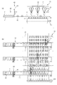
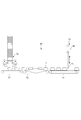
- FIG. 1 shows an overall side view of a tofu packing device to which the present invention is applied and its operation
- FIG. 1A shows continuous sheet-shaped tofu being cut along the traveling direction and having a plurality of sizes.
- B shows the action of crossing the tofu cut in the size of multiple pieces to the size of one piece
- c shows the action of finally crossing the tofu in the size of one piece. It shows the action of putting a pack on the tofu that has been crossed.
- FIG. 2 shows the tofu packing device of the first embodiment, and shows side views at the positions of the packing covering device and the packing feeding conveyor.
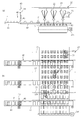
- FIG. 3 shows the tofu packing device of the second embodiment, (a) is a side view at the position of the pack covering device and the pack supply conveyor, and (b) is the pack covering device, the pack supply conveyor, and the second.
- the top view including the transfer conveyor is shown.
- FIG. 4 shows the tofu packing device of the second embodiment, (a) is a side view at the position of the pack covering device and the pack supply conveyor, and (b) is the pack covering device, the pack supply conveyor, and the second.
- the top view including the transfer conveyor is shown.
- 5A and 5B show the tofu packing device of the third embodiment, (a) is a side view at the position of the pack covering device and the pack feeding conveyor, and (b) is the packing covering device, the pack feeding conveyor, and the second.
- FIG. 6 shows the tofu packing device of the third embodiment
- (a) is a side view at the position of the pack covering device and the pack feeding conveyor
- (b) is the packing covering device, the pack feeding conveyor, and the second.
- the top view including the transfer conveyor is shown.
- FIG. 7 shows a side view of the pack covering device and the pack feeding conveyor of the tofu packing device of the fourth embodiment.
- FIG. 8 shows a top view including a pack covering device, a pack supply conveyor, and a second transfer conveyor of the tofu packing device of the fourth embodiment.
- FIG. 9 shows a side view of the pack covering device and the pack feeding conveyor of the tofu packing device of the fifth embodiment.
- FIG. 10 shows a top view including a pack covering device, a pack supply conveyor, and a second transfer conveyor of the tofu packing device of the fifth embodiment.
- FIG. 11 shows a side view of the pack covering device and the pack feeding conveyor of the tofu packing device of the sixth embodiment.
- FIG. 12 shows a top view including a pack covering device, a pack supply conveyor, and a second transfer conveyor of the tofu packing device of the sixth embodiment.
- FIG. 13 shows a side view of the pack covering device and the pack feeding conveyor of the tofu packing device of the sixth embodiment.
- FIG. 14 shows a top view including a pack covering device, a pack supply conveyor, and a second transfer conveyor of the tofu packing device of the sixth embodiment.
- FIG. 15 shows an enlarged side view of a portion of the pack supply conveyor in the tofu packing device of the sixth embodiment.
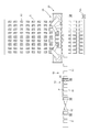
- FIG. 16 shows an enlarged side view of a portion of the pack supply conveyor in the tofu packing device of the seventh embodiment, (a) is a first step of taking out the pack, and (b) is a second step of taking out the pack. c) shows the third step of taking out the pack.
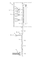
- FIG. 17 shows an overall side view of the tofu packing device of the eighth embodiment.
- FIG. 18 shows an overall side view of the tofu packing device of the ninth embodiment.
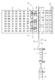
- FIG. 19 shows a side view of the pack covering device and the pack feeding conveyor of the tofu packing device of the tenth embodiment.
- FIG. 20 shows a top view including a pack covering device, a pack supply conveyor, and a second transfer conveyor of the tofu packing device of the tenth embodiment.
- FIG. 21 shows a side view of the pack covering device and the pack feeding conveyor of the tofu packing device of the tenth embodiment.
- FIG. 22 shows a top view including a pack covering device, a pack supply conveyor, and a second transfer conveyor of the tofu packing device of the tenth embodiment.
- FIGS. 1 (a) to 1 (c) show a tofu packing device to which the present invention is applied.
- the tofu packing device 1 includes an endless first transfer conveyor 3 that goes around, a cutting device 4, a second endless transfer conveyor 5 that goes around, a pack covering device 20, and a pack supply conveyor (pack).
- the first transfer conveyor 3 transfers the tip of the continuous sheet-shaped tofu A into the water tank 2.
- the cutting device 4 appropriately cuts from the tip of the continuous sheet-shaped tofu A in the vertical and horizontal directions in a state of being partially exposed from water (semi-land state), and cuts into one tofu A1 ...
- the second transfer conveyor 5 transfers the cut tofu A1 ... In a semi-land state by sequentially arranging them at intervals.
- the pack covering device 20 is installed above the second transfer conveyor 5, and packs P are sequentially covered on each tofu A1 ... Transferred by the pack supply conveyor 40 and packed.
- the rising conveyor 60 takes out each tofu A1 covered with the pack P from the water tank 2.
- the reversing device 30 is arranged on the downstream side of the rising conveyor 60 and flips the pack P (a state in which the tofu A1 ... is partially covered) upside down.
- the third transfer conveyor 50 transfers the upside-down pack P to the next processing step (packaging step).
- the traveling direction of the continuous sheet-shaped tofu is the vertical direction or the column direction
- the direction intersecting the traveling direction at right angles is the horizontal direction or the row direction.
- the first transfer conveyor 3 is for transferring the tip of the continuous sheet-shaped tofu A into the water tank 2, and the sheet-shaped tofu A is transferred from the vicinity of the peripheral edge on the rear side of the water tank 2 via the transfer plate 6. Lead to the inside of the water tank 2.
- the sheet-shaped tofu A is further guided to the second transfer conveyor 5, and is appropriately cut into a single size by the cutting device 4 from the downstream portion of the transfer plate 6 to the upstream portion of the second transfer conveyor 5.
- the cutting device 4 includes a roll cutter 4a that cuts continuous sheet-shaped tofu A along the traveling direction (longitudinal direction), and a plurality of roll cutters (2 in this example; see FIGS. 1B and 1C).
- the specific structure of the cutting device 4 is not particularly limited, and the cutting device 4 may be cut into a size of one unit (minimum unit) at a time with a grid-shaped cutting blade.
- the second transfer conveyor 5 is installed inside the water tank 2, and the cut tofu A1 ... Is sequentially placed in a semi-land state, that is, in a state where only the upper part of each tofu A1 is exposed from water. Arrange and transport at intervals.
- the pack covering device 20 covers the portion of each tofu A1 conveyed by the second transfer conveyor 5 that is exposed to water with the pack P.
- the pack P is continuously supplied to the pack covering device 20 by the pack supply conveyor 40.
- the pack covering device 20 and the pack supply conveyor 40 will be described in detail later.
- the pack supply conveyor 40 is shown in FIGS. 1 (a) to 1 (c) so as to be arranged in parallel with the traveling direction of the second transfer conveyor 5 (progressing direction of tofu). In an actual embodiment as shown in 2 and subsequent sections, the pack supply conveyor 40 is more specifically perpendicular to the traveling direction of the second transfer conveyor 5 so as to intersect the traveling direction of the second transfer conveyor 5. It is arranged so as to be.
- the rising conveyor 60 takes out each tofu A1 covered with the pack P from the water tank 2 and transfers it to the reversing device 30.
- the reversing device 30 is arranged on the downstream side of the rising conveyor 60 and flips the pack P (a state in which the tofu A1 ... is partially covered) upside down.
- the third transfer conveyor 50 transfers the upside-down pack P to the next processing step (packaging step).
- the tofu found to have defects such as chips by photography with a camera is not covered with the pack P, and is directly transferred to the reversing device 30 by the second transfer conveyor 5 or the like. Therefore, by providing a gap in the guide of the reversing device 30, it collapses and spills downward, so that defective tofu can be excluded.
- the gap between the guides can be obtained, for example, by forming the guides in a fence shape, but the fence-shaped fence may have a round cross section, a square, a triangle, etc., as long as it has a fineness and sharpness that easily bites into tofu.
- the shape of the guide is limited to a fence shape, for example, a grid shape or the like, and there may be a mechanism such that the tofu is broken into small pieces and falls into a lower saucer or a screw type waste conveyor.
- various devices In the tofu packing device 1, various devices generally do not stop during production and operate continuously in synchronization at a constant speed, but intermittent operation may be performed in synchronization with synchronization.
- the pack covering device 20 As shown in FIG. 2, in the pack covering device 20, a support rail 21 as a base is hung in the conveyor width direction above the second transfer conveyor 5 driven by the motor 5 m. A moving base portion 22 is slidably provided on the support rail 21, and a parallel link mechanism 23 is provided on the moving base portion 22. That is, the pack covering device 20 is a robot provided with a parallel link mechanism 23 including three link shafts 23a that three-dimensionally drive the tip gripping portion 23b that grips the pack P.
- the tip gripping portion 23b can have a suction type in which the pack P is sucked and sucked by a suction cup, a chuck type in which the pack P is sandwiched with forceps of 2 to 4 fingers, and a gripping structure in which these are combined.
- the method is not particularly limited as long as it can be firmly gripped by making the same.
- the moving base portion 22 and the tip gripping portion 23b may also be provided with horizontal rotation shafts and vertical rotation shafts, and a total of 4 to 6 control shafts may be provided.
- a parallel link mechanism is preferable, but a scalar robot as described later may also be used, and a horizontal distance of 200 to 300 mm per minute can be reciprocated 100 times or more (cycle) (100 CPM; abbreviation for cycle par minute). Any high-speed robot that can operate may be used. A high-speed robot capable of reciprocating 100 times or more (100 CPM; abbreviation for cycle par minute) over a horizontal distance of 0.5 to 1.5 m per minute is preferable.
- the support rail 21 which is the base exists at a position higher than the second transfer conveyor 5 to achieve space saving, and for example, by covering the space surrounded by the support rail 21 with a cover or the like, the inside of the support rail 21 can be saved.
- Cleaning of the second transfer conveyor 5 and other equipment becomes easy. For example, by cleaning the space with a cleaning nozzle capable of CIP cleaning sterilization and SIP sterilization (steam sterilization), the conveyor and various parts that the tofu comes into direct contact with can be cleaned, sterilized, and sterilized, as well as dust. It can also wash away dirt, foreign matter, etc.
- Various robots and conveyors are preferably those that have passed the IP65 or higher standard (JIS C 0920-1993), which has high anticorrosion properties against food-grade detergents and disinfectants, and high dustproof and waterproof properties. Further, it is preferable to blow steam during production and keep the inside of the refrigerator at 60 to 100 ° C. by adjusting the temperature. Further, a member such as a saucer for preventing foreign matter from being mixed may be provided below the parallel link mechanism 23, or the parallel link mechanism 23 itself may have specifications for the food industry where foreign matter does not occur.
- the pack covering device 20 is provided with an image sensor (camera device) 24 for imaging each tofu A1 ... Flowing on the transport surface 5s on the moving base portion 22.
- the pack P of each tofu A1 ... can be accurately covered according to the position of each tofu A1 ... imaged by the image sensor 24.
- a lighting member for the image sensor may be appropriately provided.
- tofu A1 Image analysis of tofu A1 is performed based on the detection signal by the image sensor 24. Therefore, when an abnormality in the tofu A1 is detected based on the image analysis, the tofu A1 is processed so as not to be covered with the pack P.
- the abnormalities of tofu A1 referred to here are, for example, those with a small size (cutting dimension) of tofu A1, those that are deformed into a trapezium or rhombus, those that are crumbled or chipped, those that have many bubbles on the cut surface, and foreign substances. It refers to the detection of substances with adhesion.
- two parallel link mechanisms 23 are installed on the left and right in the conveyor width direction. Therefore, the work area of both pack covering devices 20 is divided into two in the left-right width direction of the conveyor.
- the horizontal movement range of the pack covering device 20 is, for example, 0.5 to 1.5 meters because the arrangement width of the tofu A1 ... Is in the range of 1.0 to 3.0 meters.
- the operating accuracy is within ⁇ 2.0 mm, preferably within ⁇ 0.2 mm, more preferably within ⁇ 0.02 mm.
- the number of parallel link mechanisms 23 is not particularly limited.
- the parallel link mechanism (robot) 23 and the scalar mechanism (robot) (not shown) of the present embodiment are, for example, 100 in horizontal reciprocation over a horizontal distance of 0.2 to 3 m, preferably 0.5 to 1.5 m.
- a robot having a high-speed processing capacity (capacity capable of driving at high speed) of reciprocating (100 CPM) or more is desirable.
- the high-speed processing referred to in the present specification means a processing capacity of 4000 to 6000 or more per hour with one pack covering device 20. If there are two, the processing capacity will be double that.
- An articulated robot (serial link mechanism) may be used as long as it can process at the same speed or higher.
- the tofu packing device 1 provided with the pack supply conveyor 40 shown in FIG. 2 is the first embodiment, and each embodiment of the tofu packing device having the pack supply conveyor 40 of various embodiments will be described below.
- the pack P is supplied by the pack supply conveyor 40 provided adjacent to both sides in the width direction of the second transfer conveyor 5.
- the pack supply conveyor 40 continuously supplies packs to the pack covering device 20 from the side of the second transfer conveyor 5. As a result, the tofu packing work can be facilitated.
- the same number of pack supply conveyors 40 as the number of pack covering devices 20 can be provided. Further, as will be described later, since one pack supply conveyor 40 can be provided with at least one pack supply magazine for stocking a large number of empty packs, the operator who supplies the empty packs concentrates on the one magazine. Once the magazine is replenished to a certain extent, the pack P can be replenished to the pack supply means on the opposite side, or other work can be performed for a while. Further, the pack supply conveyor may be provided with an image sensor capable of detecting the state of the pack P.
- the pack P is supplied by the pack supply conveyor 40 provided adjacent to the second transfer conveyor 5 in the width direction.
- the pack supply conveyor 40 continuously supplies packs to the pack covering device 20 from the side of the second transfer conveyor 5.
- the same number of pack supply conveyors 40 as the number of pack covering devices 20 can be provided.
- one pack supply conveyor 40 can be provided with at least one pack supply magazine for stocking a large number of empty packs, the operator who supplies the empty packs concentrates on the one magazine. Once the magazine is replenished to a certain extent, the pack P can be replenished to the pack supply means on the opposite side, or other work can be performed for a while.
- the pack supply conveyor may be provided with an image sensor capable of detecting the state of the pack P.
- the pack supply conveyor 40 of the present embodiment extends above the second transfer conveyor 5 and continuously supplies the pack P to a position where the pack covering device 20 (three parallel link mechanisms 23) is arranged. .. As a result, the pack P can be gripped without the pack covering device 20 (three parallel link mechanisms 23) moving significantly, and the working time can be shortened.
- the pack supply conveyor 40 supplies the pack P along a direction intersecting the traveling direction of the second transfer conveyor 5, and in particular, in the embodiment, the pack supply conveyor 40 is in the traveling direction of the second transfer conveyor 5. Pack P is supplied along the vertical direction. As a result, the pack supply conveyor 40 can efficiently supply the pack P to the pack covering device 20.
- the pack supply conveyor 40 is arranged above the first pack conveyor 41 having a circular endless shape arranged on the side of the second transfer conveyor 5 and the second transfer conveyor 5, and is arranged above the first pack conveyor 5. It is provided with a second pack conveyor 42 having an endless shape that supplies the pack P supplied from the 41 to the pack covering device 20. Further, at the end of the first pack conveyor 41 on the side adjacent to the second pack conveyor 42, a stopper device 43 for temporarily stopping the progress of the pack P is provided.
- the stopper device 43 includes a motor 44 and a stopper 45, and the motor 44 drives the stopper 45 in the vertical direction at a predetermined timing to stop the progress of the pack P and advance the pack P at an appropriate timing. in this way, By providing the two pack conveyors 41 and 42 and the stopper device 43, the pack P can be supplied to the pack covering device 20 at an appropriate pace.
- FIG. 3 shows a state of timing when the parallel link mechanism 23 grips and lifts the pack P from the second pack conveyor 42
- FIG. 4 shows a state of timing when the pack P gripped by the parallel link mechanism 23 covers each tofu A1. Shown.
- FIG. 5 and 6 show the tofu packing device 1 of the third embodiment.
- three parallel link mechanisms 23 are provided on one support rail 21, and the three parallel link mechanisms 23 are arranged at the same positions in the traveling direction of the second transfer conveyor 5.
- the three support rails 21 are arranged at positions shifted along the traveling direction of the second transfer conveyor 5, and the three parallel link mechanisms 23 are also provided with the support rails accordingly.
- FIG. 5 shows a state of timing when the parallel link mechanism 23 grips and lifts the pack P from the second pack conveyor 42
- FIG. 6 shows a state of timing when the pack P gripped by the parallel link mechanism 23 covers each tofu A1. Shown.
- the pack supply conveyor 40 has a support rail 71, A moving base 72, a parallel link mechanism 73, and a pack supply magazine 75 are further provided.
- the support rail 71, the moving base portion 72, and the parallel link mechanism 73 have a configuration similar to that of the support rail 21, the moving base portion 22, and the parallel link mechanism 23. That is, above the first pack conveyor 41, the support rail 71, which is a base, is hung in the conveyor traveling direction.
- a moving base portion 72 is slidably provided on the support rail 21, and a parallel link mechanism 73 is provided on the moving base portion 72.
- the pack supply conveyor 40 includes a parallel link mechanism 73 including three link shafts 73a that three-dimensionally drive the tip grip portion 73b that grips the pack P.
- the tip gripping portion 73b can have a suction type in which the pack P is sucked and sucked by a suction cup, a chuck type in which the pack P is sandwiched with forceps of two to four fingers, and a gripping structure in which these are combined.
- the method is not particularly limited as long as it can be firmly gripped by making the same.
- the moving base portion 72 and the tip gripping portion 73b may also be provided with horizontal rotation shafts and vertical rotation shafts, and a total of 4 to 6 control shafts may be provided.
- a parallel link mechanism is preferable, but a scalar robot may also be used, and a high speed capable of operating a horizontal distance of 200 to 300 mm per minute 100 times or more (cycle) (100 CPM; abbreviation for cycle par minute). It may be a type robot.
- a high-speed robot capable of reciprocating 100 times or more (100 CPM; abbreviation for cycle par minute) over a horizontal distance of 0.5 to 1.5 m per minute is preferable.
- the pack supply magazine 75 holds a plurality of empty packs P stacked in a straight line diagonally upward.
- the parallel link mechanism 73 functions as a pack take-out robot capable of continuously supplying the packs P taken out one by one from the pack supply magazine 75. Thereby, the supply efficiency of the pack P can be improved.
- the parallel link mechanism 73 which is a pack taking-out robot, adjusts the position and angle of the tip gripping portion 73b according to the image information of the camera that captures the posture such as the position and orientation of the empty pack at the taking-out position of the pack supply magazine 75. .. After gripping the pack P, the parallel link mechanism 73 moves to a fixed position above the first pack conveyor 41, and similarly adjusts the position and angle of the tip grip portion 73b according to the information from the camera to adjust the position and angle of the tip grip portion 73b to grip the pack P. Is placed on the first pack conveyor 41. Therefore, the parallel link mechanism 73 can accurately take out the empty packs one by one from the pack supply magazine 75 and place them in the fixed positions of the first pack conveyor 41 accurately and surely.
- the stopper device on the downstream side serves as a temporary buffer for the pack, and the pack can be smoothly supplied. Is possible. Further, a plurality of parallel link mechanisms 73 may be provided for one pack supply conveyor 40.
- the packs P are stacked with the opening facing upward, and the parallel link mechanism 73 grips and takes out the pack P at the bottom, but the opening of the pack P is facing downward (
- the packs P may be stacked in a prone state), and the parallel link mechanism 73 may grip and take out the pack P at the uppermost stage.
- the pack supply conveyor 40 has a support rail 71, a moving base 72, a parallel link mechanism 73, a pack supply magazine 75, and a spare pack supply magazine. It further includes 75a.
- the moving base portion 72 is slidably provided on one support rail 71, and the parallel link mechanism 73 is provided on the moving base portion 72.
- the moving base portion 72, the parallel link mechanism 73, and the pack supply magazine 75 have the same configurations as those of the fourth embodiment.
- a spare pack supply magazine 75a is provided between the plurality of pack supply magazines 75, and the parallel link mechanism 73 as a pack take-out robot is provided.
- the packs P can be taken out from the spare pack supply magazine 75a existing in the operating range of the parallel link mechanism 73. As a result, the pack P can be continuously supplied without interruption.
- the present embodiment includes a circular endless pack taking-out conveyor 81, a reversing conveyor 82, and a pack supply magazine 76.
- the pack supply magazine 76 is not shown.
- the parallel link mechanism 73 takes out the pack P and arranges the pack P on the first pack conveyor 41 in a state where the pack P is inverted and the opening is facing downward (in a prone state).
- the pack supply magazine 76 discharges the pack P with the opening facing upward, and is arranged on the pack taking-out conveyor 81 with the opening facing upward.
- the pack supply magazine 76 holds a plurality of empty packs P stacked vertically upward in a straight line.
- the pack supply magazine 76 is a type in which packs P are taken out one by one from the bottom by a rotating rubber type, and when a claw is caught on the flange of the pack P and is taken out one by one, it is caught on the pack flange directly above. It is a mechanism that acts as a stopper and disconnects.
- the pack take-out conveyor 81 conveys the taken-out pack P to the reversing conveyor 82, and the reversing conveyor 82 reverses the pack P having an upward opening and turns the opening downward (in a prone state) and supplies the pack P to the first pack conveyor 41. To do. As a result, the pack P can be efficiently supplied.
- FIGS. 11 and 12 show the timing of the parallel link mechanism 23 gripping and lifting the pack P from the second pack conveyor 42
- FIGS. 13 and 14 show the pack P gripped by the parallel link mechanism 23 for each tofu A1. It shows the state of the timing to cover the.
- FIG. 15 shows an enlarged side view of a portion of the pack supply conveyor 40 in the tofu packing device 1 of the sixth embodiment.
- FIG. 16 shows an enlarged side view of a portion of the pack supply conveyor 40 in the tofu packing device 1 of the seventh embodiment, (a) is a first step of taking out the pack, and (b) is a second step of taking out the pack. , (C) show the third step of taking out the pack.
- the pack supply conveyor 40 of the present embodiment includes a pack take-out tool 85 and a pack extruder 86 in addition to the one shown in FIG.
- the pack P has not yet been lowered to the position of the pack take-out conveyor 81 as shown by the dotted line.
- the pack take-out tool 85 takes out the pack P from the pack supply magazine 76 and lowers it to the position of the pack take-out conveyor 81.
- the pack extruder 86 pushes the pack P to the position of the pack take-out conveyor 81 to supply the pack P.
- FIG. 17 shows the tofu packing device 1 of the eighth embodiment.
- the parallel link mechanism 23 of the pack covering device 20 grips the pack P directly from the pack supply conveyor 40 and carries it to the second transfer conveyor 5.
- the pack supply conveyor 40 is shown so as to be arranged parallel to the traveling direction of the second transfer conveyor 5 (the traveling direction of the tofu), but in reality, it is the same as in other embodiments.
- the pack supply conveyor 40 is arranged so as to intersect the traveling direction of the second transfer conveyor 5 and, more specifically, to be perpendicular to the traveling direction of the second transfer conveyor 5.
- the pack supply magazine 76 of the present embodiment is configured by a cylinder mechanism that is stacked in a straight line and pushes up a plurality of empty packs P having downward openings.
- FIG. 18 shows the tofu packing device 1 of the ninth embodiment.
- This embodiment is similar to the eighth embodiment, but the pack supply magazine 75 is used instead of the pack supply magazine 76.
- the pack supply conveyor 40 is also shown in this figure so as to be arranged parallel to the traveling direction of the second transfer conveyor 5 (the traveling direction of the tofu), it is actually the same as in other embodiments.
- the pack supply conveyor 40 is arranged so as to intersect the traveling direction of the second transfer conveyor 5 and, more specifically, to be perpendicular to the traveling direction of the second transfer conveyor 5.
- 19 to 22 show the tofu packing device 1 of the tenth embodiment.
- a support rail 25 as a base and two scalar robots 26 are provided.
- the scalar robot 26 grips the pack P using the arm 26a.
- Other functions are the same as those in the fifth embodiment.
- 19 and 20 show the timing of the scalar robot 26 gripping and lifting the pack P from the second pack conveyor 42
- FIGS. 21 and 22 show the pack P gripped by the scalar robot 26 for each tofu A1. It shows the state of the timing to cover the.
- the present invention is not limited to the above-described embodiment, and can be appropriately modified, improved, and the like.
- the material, shape, dimensions, numerical values of each component in the above-described embodiment, The form, number, arrangement location, etc. are arbitrary as long as the present invention can be achieved, and are not limited.
- Tofu packing device 3 First transfer conveyor 5 Second transfer conveyor (transfer conveyor) 20 Pack covering device 21 Support rail 22 Moving base 23 Parallel link mechanism 24 Image sensor 26 Scalar robot 30 Reversing device 40 Pack feeding device (pack feeding conveyor) 41 First pack conveyor 42 Second pack conveyor 43 Stopper device 73 Parallel link mechanism 75 Pack supply magazine 76 Pack supply magazine 81 Pack removal conveyor 82 Inversion conveyor A Continuous sheet-shaped tofu A1 Tofu P pack in units of 1
Landscapes
- Engineering & Computer Science (AREA)
- Mechanical Engineering (AREA)
- Microelectronics & Electronic Packaging (AREA)
- Life Sciences & Earth Sciences (AREA)
- Forests & Forestry (AREA)
- Beans For Foods Or Fodder (AREA)
- Health & Medical Sciences (AREA)
- Nutrition Science (AREA)
- Chemical & Material Sciences (AREA)
- Food Science & Technology (AREA)
- Polymers & Plastics (AREA)
- Botany (AREA)
- Agronomy & Crop Science (AREA)
- Container Filling Or Packaging Operations (AREA)
- Specific Conveyance Elements (AREA)
Abstract
Un dispositif d'emballage de tofu (1) est pourvu : d'un dispositif de recouvrement de paquet (20) qui recouvre respectivement, au moyen de paquets inversés (P), une pluralité de gâteaux de tofu alignés à un intervalle prédéterminé dans la direction avant-arrière et la direction droite-gauche sur une surface de transport d'un transporteur de transfert (5) ; et d'un transporteur d'alimentation en paquets (40) qui fournit en continu les paquets d'un côté du transporteur de transfert (5) au dispositif de recouvrement de paquet (20). En conséquence, des paquets vides sont fournis en continu au dispositif de recouvrement de paquet (20), ce qui permet de faciliter le travail d'emballage de tofu.
Priority Applications (5)
| Application Number | Priority Date | Filing Date | Title |
|---|---|---|---|
| CN202080090063.4A CN114845938A (zh) | 2019-12-26 | 2020-12-25 | 豆腐包装装置 |
| US17/788,703 US20230027134A1 (en) | 2019-12-26 | 2020-12-25 | Tofu packing device |
| JP2021567741A JP7212414B2 (ja) | 2019-12-26 | 2020-12-25 | 豆腐のパック詰め装置 |
| KR1020227021158A KR20220119384A (ko) | 2019-12-26 | 2020-12-25 | 두부 패킹 장치 |
| JP2022210369A JP2023024822A (ja) | 2019-12-26 | 2022-12-27 | 豆腐のパック詰め装置 |
Applications Claiming Priority (2)
| Application Number | Priority Date | Filing Date | Title |
|---|---|---|---|
| JP2019-236830 | 2019-12-26 | ||
| JP2019236830 | 2019-12-26 |
Publications (1)
| Publication Number | Publication Date |
|---|---|
| WO2021132685A1 true WO2021132685A1 (fr) | 2021-07-01 |
Family
ID=76575180
Family Applications (1)
| Application Number | Title | Priority Date | Filing Date |
|---|---|---|---|
| PCT/JP2020/049022 WO2021132685A1 (fr) | 2019-12-26 | 2020-12-25 | Dispositif d'emballage de tofu |
Country Status (5)
| Country | Link |
|---|---|
| US (1) | US20230027134A1 (fr) |
| JP (2) | JP7212414B2 (fr) |
| KR (1) | KR20220119384A (fr) |
| CN (1) | CN114845938A (fr) |
| WO (1) | WO2021132685A1 (fr) |
Cited By (1)
| Publication number | Priority date | Publication date | Assignee | Title |
|---|---|---|---|---|
| WO2023213490A1 (fr) * | 2022-05-06 | 2023-11-09 | Hastamat Verpackungstechnik Gmbh + Co. Kg | Unité de retournement et procédé pour retourner un récipient ouvert contenant des produits plats et système et procédé pour lé remplissage en portions de produits plats |
Families Citing this family (1)
| Publication number | Priority date | Publication date | Assignee | Title |
|---|---|---|---|---|
| US20230117987A1 (en) * | 2021-10-20 | 2023-04-20 | Takai Tofu & Soymilk Equipment Co. | Tofu conveying machine |
Citations (8)
| Publication number | Priority date | Publication date | Assignee | Title |
|---|---|---|---|---|
| JPS61113A (ja) * | 1985-05-08 | 1986-01-06 | 株式会社 大生機械 | 豆腐パツク詰め装置 |
| JPS61203318A (ja) * | 1985-02-28 | 1986-09-09 | サトウ商事株式会社 | 豆腐のパツク詰装置 |
| JPS63216446A (ja) * | 1987-03-05 | 1988-09-08 | ▲マス▼岡 正文 | 豆腐のパツク被着装置 |
| JPH02152605A (ja) * | 1988-11-30 | 1990-06-12 | N T Sanki:Kk | 包装体の自動詰め込み搬送装置 |
| JPH0465702U (fr) * | 1990-10-12 | 1992-06-09 | ||
| JP2007006759A (ja) * | 2005-06-29 | 2007-01-18 | Takai Seisakusho:Kk | 豆腐の自動連続パック詰め装置及びその方法 |
| WO2009150756A1 (fr) * | 2008-06-13 | 2009-12-17 | 株式会社高井製作所 | Dispositif d’emballage automatique de tofu |
| JP2015227204A (ja) * | 2014-06-02 | 2015-12-17 | 株式会社高井製作所 | 豆腐用パック設置装置及びパック詰め装置 |
Family Cites Families (2)
| Publication number | Priority date | Publication date | Assignee | Title |
|---|---|---|---|---|
| JP2014226759A (ja) | 2013-05-24 | 2014-12-08 | 株式会社ランズワーク | 豆腐製品搬送装置 |
| JP6871668B2 (ja) * | 2017-11-20 | 2021-05-12 | Pacraft株式会社 | 袋体供給システム及び袋体供給方法 |
-
2020
- 2020-12-25 CN CN202080090063.4A patent/CN114845938A/zh active Pending
- 2020-12-25 WO PCT/JP2020/049022 patent/WO2021132685A1/fr active Application Filing
- 2020-12-25 US US17/788,703 patent/US20230027134A1/en active Pending
- 2020-12-25 KR KR1020227021158A patent/KR20220119384A/ko unknown
- 2020-12-25 JP JP2021567741A patent/JP7212414B2/ja active Active
-
2022
- 2022-12-27 JP JP2022210369A patent/JP2023024822A/ja active Pending
Patent Citations (8)
| Publication number | Priority date | Publication date | Assignee | Title |
|---|---|---|---|---|
| JPS61203318A (ja) * | 1985-02-28 | 1986-09-09 | サトウ商事株式会社 | 豆腐のパツク詰装置 |
| JPS61113A (ja) * | 1985-05-08 | 1986-01-06 | 株式会社 大生機械 | 豆腐パツク詰め装置 |
| JPS63216446A (ja) * | 1987-03-05 | 1988-09-08 | ▲マス▼岡 正文 | 豆腐のパツク被着装置 |
| JPH02152605A (ja) * | 1988-11-30 | 1990-06-12 | N T Sanki:Kk | 包装体の自動詰め込み搬送装置 |
| JPH0465702U (fr) * | 1990-10-12 | 1992-06-09 | ||
| JP2007006759A (ja) * | 2005-06-29 | 2007-01-18 | Takai Seisakusho:Kk | 豆腐の自動連続パック詰め装置及びその方法 |
| WO2009150756A1 (fr) * | 2008-06-13 | 2009-12-17 | 株式会社高井製作所 | Dispositif d’emballage automatique de tofu |
| JP2015227204A (ja) * | 2014-06-02 | 2015-12-17 | 株式会社高井製作所 | 豆腐用パック設置装置及びパック詰め装置 |
Cited By (1)
| Publication number | Priority date | Publication date | Assignee | Title |
|---|---|---|---|---|
| WO2023213490A1 (fr) * | 2022-05-06 | 2023-11-09 | Hastamat Verpackungstechnik Gmbh + Co. Kg | Unité de retournement et procédé pour retourner un récipient ouvert contenant des produits plats et système et procédé pour lé remplissage en portions de produits plats |
Also Published As
| Publication number | Publication date |
|---|---|
| KR20220119384A (ko) | 2022-08-29 |
| US20230027134A1 (en) | 2023-01-26 |
| JP2023024822A (ja) | 2023-02-16 |
| JP7212414B2 (ja) | 2023-01-25 |
| CN114845938A (zh) | 2022-08-02 |
| JPWO2021132685A1 (fr) | 2021-07-01 |
Similar Documents
| Publication | Publication Date | Title |
|---|---|---|
| WO2021132685A1 (fr) | Dispositif d'emballage de tofu | |
| TWI445501B (zh) | 貝類固定及打開裝置與其方法 | |
| JP2015051782A (ja) | 包装システム | |
| KR101238176B1 (ko) | 병버섯 자동 수확장치 | |
| JP2003034544A (ja) | 板ガラスの割断機構およびトリミング装置 | |
| JP2023106462A (ja) | 豆腐のパック詰め装置 | |
| JP2007006759A (ja) | 豆腐の自動連続パック詰め装置及びその方法 | |
| CN106742248B (zh) | 自助提款机自动包装生产线及采用该生产线的包装工艺 | |
| WO2021199389A1 (fr) | Appareil d'emballage de tofu | |
| TW201739536A (zh) | 用於傳送工作件的運輸方法 | |
| JP2007112515A (ja) | 包装されるべき少物品を帯状シートのカップ部中へと所定の位置・姿勢に配列して送り込み引き渡すための装置 | |
| JP6379012B2 (ja) | 物品移送装置 | |
| JP6691227B2 (ja) | 搬送装置および移送システム | |
| ES2494417T3 (es) | Procedimiento para la operación de un robot y dispositivo con un robot | |
| ATE364554T1 (de) | Vorrichtung zum überführen von nahrungsmitteln von schneidmaschinen zu verpackungsmaschinen | |
| JP5080684B1 (ja) | 耳落とし装置 | |
| US11858753B2 (en) | Inversion guide device and tofu production device | |
| JP2023015454A (ja) | 包装機用ヒートシール装置 | |
| CN111661637A (zh) | 抓持装置、分离装置及抓持物体的方法和抓持装置的用途 | |
| CN215554690U (zh) | 一种水饺自动毛刷机 | |
| CN220843175U (zh) | 包装手套用传送装置 | |
| CN108723610A (zh) | 一种织带镭射裁切机 | |
| CN213648612U (zh) | 一种塑料制品吹制设备 | |
| CN114248985B (zh) | 一种拆包设备 | |
| JP3235900B2 (ja) | 豆腐製造装置の豆腐送給機構 |
Legal Events
| Date | Code | Title | Description |
|---|---|---|---|
| 121 | Ep: the epo has been informed by wipo that ep was designated in this application |
Ref document number: 20907796 Country of ref document: EP Kind code of ref document: A1 |
|
| ENP | Entry into the national phase |
Ref document number: 2021567741 Country of ref document: JP Kind code of ref document: A |
|
| NENP | Non-entry into the national phase |
Ref country code: DE |
|
| 122 | Ep: pct application non-entry in european phase |
Ref document number: 20907796 Country of ref document: EP Kind code of ref document: A1 |