WO2021132685A1 - Tofu packing device - Google Patents
Tofu packing device Download PDFInfo
- Publication number
- WO2021132685A1 WO2021132685A1 PCT/JP2020/049022 JP2020049022W WO2021132685A1 WO 2021132685 A1 WO2021132685 A1 WO 2021132685A1 JP 2020049022 W JP2020049022 W JP 2020049022W WO 2021132685 A1 WO2021132685 A1 WO 2021132685A1
- Authority
- WO
- WIPO (PCT)
- Prior art keywords
- pack
- conveyor
- tofu
- packing device
- tofu packing
- Prior art date
Links
Images


Classifications
-
- B—PERFORMING OPERATIONS; TRANSPORTING
- B65—CONVEYING; PACKING; STORING; HANDLING THIN OR FILAMENTARY MATERIAL
- B65B—MACHINES, APPARATUS OR DEVICES FOR, OR METHODS OF, PACKAGING ARTICLES OR MATERIALS; UNPACKING
- B65B25/00—Packaging other articles presenting special problems
- B65B25/001—Packaging other articles presenting special problems of foodstuffs, combined with their conservation
-
- B—PERFORMING OPERATIONS; TRANSPORTING
- B26—HAND CUTTING TOOLS; CUTTING; SEVERING
- B26D—CUTTING; DETAILS COMMON TO MACHINES FOR PERFORATING, PUNCHING, CUTTING-OUT, STAMPING-OUT OR SEVERING
- B26D9/00—Cutting apparatus combined with punching or perforating apparatus or with dissimilar cutting apparatus
-
- B—PERFORMING OPERATIONS; TRANSPORTING
- B65—CONVEYING; PACKING; STORING; HANDLING THIN OR FILAMENTARY MATERIAL
- B65B—MACHINES, APPARATUS OR DEVICES FOR, OR METHODS OF, PACKAGING ARTICLES OR MATERIALS; UNPACKING
- B65B25/00—Packaging other articles presenting special problems
- B65B25/06—Packaging slices or specially-shaped pieces of meat, cheese, or other plastic or tacky products
-
- B—PERFORMING OPERATIONS; TRANSPORTING
- B65—CONVEYING; PACKING; STORING; HANDLING THIN OR FILAMENTARY MATERIAL
- B65B—MACHINES, APPARATUS OR DEVICES FOR, OR METHODS OF, PACKAGING ARTICLES OR MATERIALS; UNPACKING
- B65B35/00—Supplying, feeding, arranging or orientating articles to be packaged
- B65B35/02—Supply magazines
-
- B—PERFORMING OPERATIONS; TRANSPORTING
- B65—CONVEYING; PACKING; STORING; HANDLING THIN OR FILAMENTARY MATERIAL
- B65B—MACHINES, APPARATUS OR DEVICES FOR, OR METHODS OF, PACKAGING ARTICLES OR MATERIALS; UNPACKING
- B65B35/00—Supplying, feeding, arranging or orientating articles to be packaged
- B65B35/10—Feeding, e.g. conveying, single articles
- B65B35/24—Feeding, e.g. conveying, single articles by endless belts or chains
-
- B—PERFORMING OPERATIONS; TRANSPORTING
- B65—CONVEYING; PACKING; STORING; HANDLING THIN OR FILAMENTARY MATERIAL
- B65B—MACHINES, APPARATUS OR DEVICES FOR, OR METHODS OF, PACKAGING ARTICLES OR MATERIALS; UNPACKING
- B65B43/00—Forming, feeding, opening or setting-up containers or receptacles in association with packaging
- B65B43/42—Feeding or positioning bags, boxes, or cartons in the distended, opened, or set-up state; Feeding preformed rigid containers, e.g. tins, capsules, glass tubes, glasses, to the packaging position; Locating containers or receptacles at the filling position; Supporting containers or receptacles during the filling operation
- B65B43/46—Feeding or positioning bags, boxes, or cartons in the distended, opened, or set-up state; Feeding preformed rigid containers, e.g. tins, capsules, glass tubes, glasses, to the packaging position; Locating containers or receptacles at the filling position; Supporting containers or receptacles during the filling operation using grippers
-
- B—PERFORMING OPERATIONS; TRANSPORTING
- B65—CONVEYING; PACKING; STORING; HANDLING THIN OR FILAMENTARY MATERIAL
- B65B—MACHINES, APPARATUS OR DEVICES FOR, OR METHODS OF, PACKAGING ARTICLES OR MATERIALS; UNPACKING
- B65B43/00—Forming, feeding, opening or setting-up containers or receptacles in association with packaging
- B65B43/42—Feeding or positioning bags, boxes, or cartons in the distended, opened, or set-up state; Feeding preformed rigid containers, e.g. tins, capsules, glass tubes, glasses, to the packaging position; Locating containers or receptacles at the filling position; Supporting containers or receptacles during the filling operation
- B65B43/52—Feeding or positioning bags, boxes, or cartons in the distended, opened, or set-up state; Feeding preformed rigid containers, e.g. tins, capsules, glass tubes, glasses, to the packaging position; Locating containers or receptacles at the filling position; Supporting containers or receptacles during the filling operation using roller-ways or endless conveyors
-
- B—PERFORMING OPERATIONS; TRANSPORTING
- B65—CONVEYING; PACKING; STORING; HANDLING THIN OR FILAMENTARY MATERIAL
- B65B—MACHINES, APPARATUS OR DEVICES FOR, OR METHODS OF, PACKAGING ARTICLES OR MATERIALS; UNPACKING
- B65B5/00—Packaging individual articles in containers or receptacles, e.g. bags, sacks, boxes, cartons, cans, jars
- B65B5/04—Packaging single articles
-
- B—PERFORMING OPERATIONS; TRANSPORTING
- B65—CONVEYING; PACKING; STORING; HANDLING THIN OR FILAMENTARY MATERIAL
- B65B—MACHINES, APPARATUS OR DEVICES FOR, OR METHODS OF, PACKAGING ARTICLES OR MATERIALS; UNPACKING
- B65B57/00—Automatic control, checking, warning, or safety devices
- B65B57/02—Automatic control, checking, warning, or safety devices responsive to absence, presence, abnormal feed, or misplacement of binding or wrapping material, containers, or packages
- B65B57/08—Automatic control, checking, warning, or safety devices responsive to absence, presence, abnormal feed, or misplacement of binding or wrapping material, containers, or packages and operating to stop, or to control the speed of, the machine as a whole
-
- B—PERFORMING OPERATIONS; TRANSPORTING
- B65—CONVEYING; PACKING; STORING; HANDLING THIN OR FILAMENTARY MATERIAL
- B65B—MACHINES, APPARATUS OR DEVICES FOR, OR METHODS OF, PACKAGING ARTICLES OR MATERIALS; UNPACKING
- B65B57/00—Automatic control, checking, warning, or safety devices
- B65B57/10—Automatic control, checking, warning, or safety devices responsive to absence, presence, abnormal feed, or misplacement of articles or materials to be packaged
- B65B57/14—Automatic control, checking, warning, or safety devices responsive to absence, presence, abnormal feed, or misplacement of articles or materials to be packaged and operating to control, or stop, the feed of articles or material to be packaged
-
- B—PERFORMING OPERATIONS; TRANSPORTING
- B65—CONVEYING; PACKING; STORING; HANDLING THIN OR FILAMENTARY MATERIAL
- B65B—MACHINES, APPARATUS OR DEVICES FOR, OR METHODS OF, PACKAGING ARTICLES OR MATERIALS; UNPACKING
- B65B57/00—Automatic control, checking, warning, or safety devices
- B65B57/10—Automatic control, checking, warning, or safety devices responsive to absence, presence, abnormal feed, or misplacement of articles or materials to be packaged
- B65B57/16—Automatic control, checking, warning, or safety devices responsive to absence, presence, abnormal feed, or misplacement of articles or materials to be packaged and operating to stop, or to control the speed of, the machine as a whole
-
- B—PERFORMING OPERATIONS; TRANSPORTING
- B65—CONVEYING; PACKING; STORING; HANDLING THIN OR FILAMENTARY MATERIAL
- B65B—MACHINES, APPARATUS OR DEVICES FOR, OR METHODS OF, PACKAGING ARTICLES OR MATERIALS; UNPACKING
- B65B65/00—Details peculiar to packaging machines and not otherwise provided for; Arrangements of such details
- B65B65/003—Packaging lines, e.g. general layout
- B65B65/006—Multiple parallel packaging lines
-
- B—PERFORMING OPERATIONS; TRANSPORTING
- B65—CONVEYING; PACKING; STORING; HANDLING THIN OR FILAMENTARY MATERIAL
- B65G—TRANSPORT OR STORAGE DEVICES, e.g. CONVEYORS FOR LOADING OR TIPPING, SHOP CONVEYOR SYSTEMS OR PNEUMATIC TUBE CONVEYORS
- B65G47/00—Article or material-handling devices associated with conveyors; Methods employing such devices
- B65G47/22—Devices influencing the relative position or the attitude of articles during transit by conveyors
- B65G47/24—Devices influencing the relative position or the attitude of articles during transit by conveyors orientating the articles
- B65G47/248—Devices influencing the relative position or the attitude of articles during transit by conveyors orientating the articles by turning over or inverting them
-
- A—HUMAN NECESSITIES
- A23—FOODS OR FOODSTUFFS; TREATMENT THEREOF, NOT COVERED BY OTHER CLASSES
- A23L—FOODS, FOODSTUFFS, OR NON-ALCOHOLIC BEVERAGES, NOT COVERED BY SUBCLASSES A21D OR A23B-A23J; THEIR PREPARATION OR TREATMENT, e.g. COOKING, MODIFICATION OF NUTRITIVE QUALITIES, PHYSICAL TREATMENT; PRESERVATION OF FOODS OR FOODSTUFFS, IN GENERAL
- A23L11/00—Pulses, i.e. fruits of leguminous plants, for production of food; Products from legumes; Preparation or treatment thereof
- A23L11/40—Pulse curds
- A23L11/45—Soy bean curds, e.g. tofu
-
- B—PERFORMING OPERATIONS; TRANSPORTING
- B26—HAND CUTTING TOOLS; CUTTING; SEVERING
- B26D—CUTTING; DETAILS COMMON TO MACHINES FOR PERFORATING, PUNCHING, CUTTING-OUT, STAMPING-OUT OR SEVERING
- B26D1/00—Cutting through work characterised by the nature or movement of the cutting member or particular materials not otherwise provided for; Apparatus or machines therefor; Cutting members therefor
- B26D1/01—Cutting through work characterised by the nature or movement of the cutting member or particular materials not otherwise provided for; Apparatus or machines therefor; Cutting members therefor involving a cutting member which does not travel with the work
- B26D1/04—Cutting through work characterised by the nature or movement of the cutting member or particular materials not otherwise provided for; Apparatus or machines therefor; Cutting members therefor involving a cutting member which does not travel with the work having a linearly-movable cutting member
- B26D1/06—Cutting through work characterised by the nature or movement of the cutting member or particular materials not otherwise provided for; Apparatus or machines therefor; Cutting members therefor involving a cutting member which does not travel with the work having a linearly-movable cutting member wherein the cutting member reciprocates
- B26D1/08—Cutting through work characterised by the nature or movement of the cutting member or particular materials not otherwise provided for; Apparatus or machines therefor; Cutting members therefor involving a cutting member which does not travel with the work having a linearly-movable cutting member wherein the cutting member reciprocates of the guillotine type
-
- B—PERFORMING OPERATIONS; TRANSPORTING
- B26—HAND CUTTING TOOLS; CUTTING; SEVERING
- B26D—CUTTING; DETAILS COMMON TO MACHINES FOR PERFORATING, PUNCHING, CUTTING-OUT, STAMPING-OUT OR SEVERING
- B26D1/00—Cutting through work characterised by the nature or movement of the cutting member or particular materials not otherwise provided for; Apparatus or machines therefor; Cutting members therefor
- B26D1/01—Cutting through work characterised by the nature or movement of the cutting member or particular materials not otherwise provided for; Apparatus or machines therefor; Cutting members therefor involving a cutting member which does not travel with the work
- B26D1/12—Cutting through work characterised by the nature or movement of the cutting member or particular materials not otherwise provided for; Apparatus or machines therefor; Cutting members therefor involving a cutting member which does not travel with the work having a cutting member moving about an axis
- B26D1/14—Cutting through work characterised by the nature or movement of the cutting member or particular materials not otherwise provided for; Apparatus or machines therefor; Cutting members therefor involving a cutting member which does not travel with the work having a cutting member moving about an axis with a circular cutting member, e.g. disc cutter
-
- B—PERFORMING OPERATIONS; TRANSPORTING
- B26—HAND CUTTING TOOLS; CUTTING; SEVERING
- B26D—CUTTING; DETAILS COMMON TO MACHINES FOR PERFORATING, PUNCHING, CUTTING-OUT, STAMPING-OUT OR SEVERING
- B26D2210/00—Machines or methods used for cutting special materials
- B26D2210/02—Machines or methods used for cutting special materials for cutting food products, e.g. food slicers
Definitions
- the present invention relates to a tofu packing device that continuously and automatically performs from cutting to packing of continuously produced sheet-shaped tofu.
- silken tofu is coagulated and aged in a mold with a coagulant added to the raw material soymilk, and then cotton tofu is coagulated and aged in a suitable container (ex. Then, this is poured into a mold, compacted and molded, then taken out from the mold, cut into a predetermined size, and packed in a pack.
- Patent Document 1 describes a first transfer conveyor for transferring formwork tofu into a water tank, and A cutting means for sequentially cutting the formwork tofu transferred into the water tank in the vertical and horizontal directions, a second transfer conveyor for sequentially transferring the cut tofu to the outside of the water tank, and installation after the downstream of the second transfer conveyor.
- an automatic continuous packing device for tofu having a packing means for sequentially or simultaneously packing a plurality of transferred tofu.
- Patent Document 2 includes a holding head having a pair of holding bodies arranged so as to face each other, and holding the tofu product by sandwiching and holding the pair of holding bodies by making the pair of holding bodies relatively close to each other, and a holding head thereof.
- a tofu product transporting device comprising a head moving device for moving the tofu product, wherein the clamp is attached to a contact surface of the pair of sandwiches with each tofu product.
- a tofu product transporting device provided with anti-slip means for preventing the held tofu product from slipping off.
- Patent Document 1 In the tofu packing device, it is possible to achieve smooth work by grasping the relative relationship including the relative positioning of the tofu and the empty pack before packing the tofu.
- Patent Document 1 the posture information and the like are not grasped by a camera or the like for an empty pack, and it is assumed that the robot holds the empty pack even if the pack is missing or the position and posture of the pack are deviated.
- Patent Document 2 Since the operation of covering the tofu is performed, there is a possibility that the smooth covering operation may not be performed.
- Patent Document 2 adopts a method of grasping soft tofu and dropping it into an empty pack, it is naturally impossible to operate at high speed, and the processing capacity is limited.
- the present invention provides a tofu packing device that enables smooth processing by preparing an empty pack before filling the tofu.
- the tofu packing device includes a packing covering device for flipping a pack over a plurality of tofu arranged at predetermined intervals in front, back, left and right on the transport surface of a transfer conveyor.
- a pack supply device for continuously supplying a pack to the pack covering device from the side of the transfer conveyor is provided.
- the pack supply device extends above the transfer conveyor and supplies the pack to a position where the pack covering device is arranged.
- the pack supply device supplies packs along a direction intersecting the traveling direction of the transfer conveyor.
- the pack supply device supplies packs along a direction perpendicular to the traveling direction of the transfer conveyor.
- the pack feeding device is a first pack conveyor arranged on the side of the transfer conveyor and a pack covering device arranged above the transfer conveyor and supplied from the first pack conveyor.
- a second pack conveyor is provided.
- the pack supply device further includes a stopper device that temporarily stops the progress of the pack on the first pack conveyor.
- the pack supply device further includes a pack supply magazine that holds a plurality of empty packs, and continuously supplies the packs taken out from the pack supply magazine.
- the pack supply device further includes a pack take-out robot capable of taking out packs one by one from the pack supply magazine.
- the pack take-out robot takes out the pack from a spare pack supply magazine existing within the operating range of the pack take-out robot.
- the pack feeding device includes a pack feeding magazine that holds a plurality of empty packs, and a pack feeding magazine.
- a pack take-out conveyor that conveys the pack discharged from the pack supply magazine with the opening facing upward, and a reversing conveyor that inverts the pack whose opening conveyed by the pack taking-out conveyor faces upward and turns the opening downward. Be prepared.
- At least one of the pack supply device and the transfer conveyor has an IP of 65 or higher.
- the pack supply device continuously supplies empty packs before filling the tofu to the pack covering device, the tofu packing work can be facilitated.
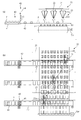
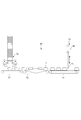
- FIG. 1 shows an overall side view of a tofu packing device to which the present invention is applied and its operation
- FIG. 1A shows continuous sheet-shaped tofu being cut along the traveling direction and having a plurality of sizes.
- B shows the action of crossing the tofu cut in the size of multiple pieces to the size of one piece
- c shows the action of finally crossing the tofu in the size of one piece. It shows the action of putting a pack on the tofu that has been crossed.
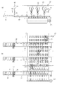
- FIG. 2 shows the tofu packing device of the first embodiment, and shows side views at the positions of the packing covering device and the packing feeding conveyor.
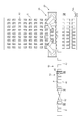
- FIG. 3 shows the tofu packing device of the second embodiment, (a) is a side view at the position of the pack covering device and the pack supply conveyor, and (b) is the pack covering device, the pack supply conveyor, and the second.
- the top view including the transfer conveyor is shown.
- FIG. 4 shows the tofu packing device of the second embodiment, (a) is a side view at the position of the pack covering device and the pack supply conveyor, and (b) is the pack covering device, the pack supply conveyor, and the second.
- the top view including the transfer conveyor is shown.
- 5A and 5B show the tofu packing device of the third embodiment, (a) is a side view at the position of the pack covering device and the pack feeding conveyor, and (b) is the packing covering device, the pack feeding conveyor, and the second.
- FIG. 6 shows the tofu packing device of the third embodiment
- (a) is a side view at the position of the pack covering device and the pack feeding conveyor
- (b) is the packing covering device, the pack feeding conveyor, and the second.
- the top view including the transfer conveyor is shown.
- FIG. 7 shows a side view of the pack covering device and the pack feeding conveyor of the tofu packing device of the fourth embodiment.
- FIG. 8 shows a top view including a pack covering device, a pack supply conveyor, and a second transfer conveyor of the tofu packing device of the fourth embodiment.
- FIG. 9 shows a side view of the pack covering device and the pack feeding conveyor of the tofu packing device of the fifth embodiment.
- FIG. 10 shows a top view including a pack covering device, a pack supply conveyor, and a second transfer conveyor of the tofu packing device of the fifth embodiment.
- FIG. 11 shows a side view of the pack covering device and the pack feeding conveyor of the tofu packing device of the sixth embodiment.
- FIG. 12 shows a top view including a pack covering device, a pack supply conveyor, and a second transfer conveyor of the tofu packing device of the sixth embodiment.
- FIG. 13 shows a side view of the pack covering device and the pack feeding conveyor of the tofu packing device of the sixth embodiment.
- FIG. 14 shows a top view including a pack covering device, a pack supply conveyor, and a second transfer conveyor of the tofu packing device of the sixth embodiment.
- FIG. 15 shows an enlarged side view of a portion of the pack supply conveyor in the tofu packing device of the sixth embodiment.
- FIG. 16 shows an enlarged side view of a portion of the pack supply conveyor in the tofu packing device of the seventh embodiment, (a) is a first step of taking out the pack, and (b) is a second step of taking out the pack. c) shows the third step of taking out the pack.
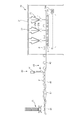
- FIG. 17 shows an overall side view of the tofu packing device of the eighth embodiment.
- FIG. 18 shows an overall side view of the tofu packing device of the ninth embodiment.
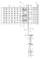
- FIG. 19 shows a side view of the pack covering device and the pack feeding conveyor of the tofu packing device of the tenth embodiment.
- FIG. 20 shows a top view including a pack covering device, a pack supply conveyor, and a second transfer conveyor of the tofu packing device of the tenth embodiment.
- FIG. 21 shows a side view of the pack covering device and the pack feeding conveyor of the tofu packing device of the tenth embodiment.
- FIG. 22 shows a top view including a pack covering device, a pack supply conveyor, and a second transfer conveyor of the tofu packing device of the tenth embodiment.
- FIGS. 1 (a) to 1 (c) show a tofu packing device to which the present invention is applied.
- the tofu packing device 1 includes an endless first transfer conveyor 3 that goes around, a cutting device 4, a second endless transfer conveyor 5 that goes around, a pack covering device 20, and a pack supply conveyor (pack).
- the first transfer conveyor 3 transfers the tip of the continuous sheet-shaped tofu A into the water tank 2.
- the cutting device 4 appropriately cuts from the tip of the continuous sheet-shaped tofu A in the vertical and horizontal directions in a state of being partially exposed from water (semi-land state), and cuts into one tofu A1 ...
- the second transfer conveyor 5 transfers the cut tofu A1 ... In a semi-land state by sequentially arranging them at intervals.
- the pack covering device 20 is installed above the second transfer conveyor 5, and packs P are sequentially covered on each tofu A1 ... Transferred by the pack supply conveyor 40 and packed.
- the rising conveyor 60 takes out each tofu A1 covered with the pack P from the water tank 2.
- the reversing device 30 is arranged on the downstream side of the rising conveyor 60 and flips the pack P (a state in which the tofu A1 ... is partially covered) upside down.
- the third transfer conveyor 50 transfers the upside-down pack P to the next processing step (packaging step).
- the traveling direction of the continuous sheet-shaped tofu is the vertical direction or the column direction
- the direction intersecting the traveling direction at right angles is the horizontal direction or the row direction.
- the first transfer conveyor 3 is for transferring the tip of the continuous sheet-shaped tofu A into the water tank 2, and the sheet-shaped tofu A is transferred from the vicinity of the peripheral edge on the rear side of the water tank 2 via the transfer plate 6. Lead to the inside of the water tank 2.
- the sheet-shaped tofu A is further guided to the second transfer conveyor 5, and is appropriately cut into a single size by the cutting device 4 from the downstream portion of the transfer plate 6 to the upstream portion of the second transfer conveyor 5.
- the cutting device 4 includes a roll cutter 4a that cuts continuous sheet-shaped tofu A along the traveling direction (longitudinal direction), and a plurality of roll cutters (2 in this example; see FIGS. 1B and 1C).
- the specific structure of the cutting device 4 is not particularly limited, and the cutting device 4 may be cut into a size of one unit (minimum unit) at a time with a grid-shaped cutting blade.
- the second transfer conveyor 5 is installed inside the water tank 2, and the cut tofu A1 ... Is sequentially placed in a semi-land state, that is, in a state where only the upper part of each tofu A1 is exposed from water. Arrange and transport at intervals.
- the pack covering device 20 covers the portion of each tofu A1 conveyed by the second transfer conveyor 5 that is exposed to water with the pack P.
- the pack P is continuously supplied to the pack covering device 20 by the pack supply conveyor 40.
- the pack covering device 20 and the pack supply conveyor 40 will be described in detail later.
- the pack supply conveyor 40 is shown in FIGS. 1 (a) to 1 (c) so as to be arranged in parallel with the traveling direction of the second transfer conveyor 5 (progressing direction of tofu). In an actual embodiment as shown in 2 and subsequent sections, the pack supply conveyor 40 is more specifically perpendicular to the traveling direction of the second transfer conveyor 5 so as to intersect the traveling direction of the second transfer conveyor 5. It is arranged so as to be.
- the rising conveyor 60 takes out each tofu A1 covered with the pack P from the water tank 2 and transfers it to the reversing device 30.
- the reversing device 30 is arranged on the downstream side of the rising conveyor 60 and flips the pack P (a state in which the tofu A1 ... is partially covered) upside down.
- the third transfer conveyor 50 transfers the upside-down pack P to the next processing step (packaging step).
- the tofu found to have defects such as chips by photography with a camera is not covered with the pack P, and is directly transferred to the reversing device 30 by the second transfer conveyor 5 or the like. Therefore, by providing a gap in the guide of the reversing device 30, it collapses and spills downward, so that defective tofu can be excluded.
- the gap between the guides can be obtained, for example, by forming the guides in a fence shape, but the fence-shaped fence may have a round cross section, a square, a triangle, etc., as long as it has a fineness and sharpness that easily bites into tofu.
- the shape of the guide is limited to a fence shape, for example, a grid shape or the like, and there may be a mechanism such that the tofu is broken into small pieces and falls into a lower saucer or a screw type waste conveyor.
- various devices In the tofu packing device 1, various devices generally do not stop during production and operate continuously in synchronization at a constant speed, but intermittent operation may be performed in synchronization with synchronization.
- the pack covering device 20 As shown in FIG. 2, in the pack covering device 20, a support rail 21 as a base is hung in the conveyor width direction above the second transfer conveyor 5 driven by the motor 5 m. A moving base portion 22 is slidably provided on the support rail 21, and a parallel link mechanism 23 is provided on the moving base portion 22. That is, the pack covering device 20 is a robot provided with a parallel link mechanism 23 including three link shafts 23a that three-dimensionally drive the tip gripping portion 23b that grips the pack P.
- the tip gripping portion 23b can have a suction type in which the pack P is sucked and sucked by a suction cup, a chuck type in which the pack P is sandwiched with forceps of 2 to 4 fingers, and a gripping structure in which these are combined.
- the method is not particularly limited as long as it can be firmly gripped by making the same.
- the moving base portion 22 and the tip gripping portion 23b may also be provided with horizontal rotation shafts and vertical rotation shafts, and a total of 4 to 6 control shafts may be provided.
- a parallel link mechanism is preferable, but a scalar robot as described later may also be used, and a horizontal distance of 200 to 300 mm per minute can be reciprocated 100 times or more (cycle) (100 CPM; abbreviation for cycle par minute). Any high-speed robot that can operate may be used. A high-speed robot capable of reciprocating 100 times or more (100 CPM; abbreviation for cycle par minute) over a horizontal distance of 0.5 to 1.5 m per minute is preferable.
- the support rail 21 which is the base exists at a position higher than the second transfer conveyor 5 to achieve space saving, and for example, by covering the space surrounded by the support rail 21 with a cover or the like, the inside of the support rail 21 can be saved.
- Cleaning of the second transfer conveyor 5 and other equipment becomes easy. For example, by cleaning the space with a cleaning nozzle capable of CIP cleaning sterilization and SIP sterilization (steam sterilization), the conveyor and various parts that the tofu comes into direct contact with can be cleaned, sterilized, and sterilized, as well as dust. It can also wash away dirt, foreign matter, etc.
- Various robots and conveyors are preferably those that have passed the IP65 or higher standard (JIS C 0920-1993), which has high anticorrosion properties against food-grade detergents and disinfectants, and high dustproof and waterproof properties. Further, it is preferable to blow steam during production and keep the inside of the refrigerator at 60 to 100 ° C. by adjusting the temperature. Further, a member such as a saucer for preventing foreign matter from being mixed may be provided below the parallel link mechanism 23, or the parallel link mechanism 23 itself may have specifications for the food industry where foreign matter does not occur.
- the pack covering device 20 is provided with an image sensor (camera device) 24 for imaging each tofu A1 ... Flowing on the transport surface 5s on the moving base portion 22.
- the pack P of each tofu A1 ... can be accurately covered according to the position of each tofu A1 ... imaged by the image sensor 24.
- a lighting member for the image sensor may be appropriately provided.
- tofu A1 Image analysis of tofu A1 is performed based on the detection signal by the image sensor 24. Therefore, when an abnormality in the tofu A1 is detected based on the image analysis, the tofu A1 is processed so as not to be covered with the pack P.
- the abnormalities of tofu A1 referred to here are, for example, those with a small size (cutting dimension) of tofu A1, those that are deformed into a trapezium or rhombus, those that are crumbled or chipped, those that have many bubbles on the cut surface, and foreign substances. It refers to the detection of substances with adhesion.
- two parallel link mechanisms 23 are installed on the left and right in the conveyor width direction. Therefore, the work area of both pack covering devices 20 is divided into two in the left-right width direction of the conveyor.
- the horizontal movement range of the pack covering device 20 is, for example, 0.5 to 1.5 meters because the arrangement width of the tofu A1 ... Is in the range of 1.0 to 3.0 meters.
- the operating accuracy is within ⁇ 2.0 mm, preferably within ⁇ 0.2 mm, more preferably within ⁇ 0.02 mm.
- the number of parallel link mechanisms 23 is not particularly limited.
- the parallel link mechanism (robot) 23 and the scalar mechanism (robot) (not shown) of the present embodiment are, for example, 100 in horizontal reciprocation over a horizontal distance of 0.2 to 3 m, preferably 0.5 to 1.5 m.
- a robot having a high-speed processing capacity (capacity capable of driving at high speed) of reciprocating (100 CPM) or more is desirable.
- the high-speed processing referred to in the present specification means a processing capacity of 4000 to 6000 or more per hour with one pack covering device 20. If there are two, the processing capacity will be double that.
- An articulated robot (serial link mechanism) may be used as long as it can process at the same speed or higher.
- the tofu packing device 1 provided with the pack supply conveyor 40 shown in FIG. 2 is the first embodiment, and each embodiment of the tofu packing device having the pack supply conveyor 40 of various embodiments will be described below.
- the pack P is supplied by the pack supply conveyor 40 provided adjacent to both sides in the width direction of the second transfer conveyor 5.
- the pack supply conveyor 40 continuously supplies packs to the pack covering device 20 from the side of the second transfer conveyor 5. As a result, the tofu packing work can be facilitated.
- the same number of pack supply conveyors 40 as the number of pack covering devices 20 can be provided. Further, as will be described later, since one pack supply conveyor 40 can be provided with at least one pack supply magazine for stocking a large number of empty packs, the operator who supplies the empty packs concentrates on the one magazine. Once the magazine is replenished to a certain extent, the pack P can be replenished to the pack supply means on the opposite side, or other work can be performed for a while. Further, the pack supply conveyor may be provided with an image sensor capable of detecting the state of the pack P.
- the pack P is supplied by the pack supply conveyor 40 provided adjacent to the second transfer conveyor 5 in the width direction.
- the pack supply conveyor 40 continuously supplies packs to the pack covering device 20 from the side of the second transfer conveyor 5.
- the same number of pack supply conveyors 40 as the number of pack covering devices 20 can be provided.
- one pack supply conveyor 40 can be provided with at least one pack supply magazine for stocking a large number of empty packs, the operator who supplies the empty packs concentrates on the one magazine. Once the magazine is replenished to a certain extent, the pack P can be replenished to the pack supply means on the opposite side, or other work can be performed for a while.
- the pack supply conveyor may be provided with an image sensor capable of detecting the state of the pack P.
- the pack supply conveyor 40 of the present embodiment extends above the second transfer conveyor 5 and continuously supplies the pack P to a position where the pack covering device 20 (three parallel link mechanisms 23) is arranged. .. As a result, the pack P can be gripped without the pack covering device 20 (three parallel link mechanisms 23) moving significantly, and the working time can be shortened.
- the pack supply conveyor 40 supplies the pack P along a direction intersecting the traveling direction of the second transfer conveyor 5, and in particular, in the embodiment, the pack supply conveyor 40 is in the traveling direction of the second transfer conveyor 5. Pack P is supplied along the vertical direction. As a result, the pack supply conveyor 40 can efficiently supply the pack P to the pack covering device 20.
- the pack supply conveyor 40 is arranged above the first pack conveyor 41 having a circular endless shape arranged on the side of the second transfer conveyor 5 and the second transfer conveyor 5, and is arranged above the first pack conveyor 5. It is provided with a second pack conveyor 42 having an endless shape that supplies the pack P supplied from the 41 to the pack covering device 20. Further, at the end of the first pack conveyor 41 on the side adjacent to the second pack conveyor 42, a stopper device 43 for temporarily stopping the progress of the pack P is provided.
- the stopper device 43 includes a motor 44 and a stopper 45, and the motor 44 drives the stopper 45 in the vertical direction at a predetermined timing to stop the progress of the pack P and advance the pack P at an appropriate timing. in this way, By providing the two pack conveyors 41 and 42 and the stopper device 43, the pack P can be supplied to the pack covering device 20 at an appropriate pace.
- FIG. 3 shows a state of timing when the parallel link mechanism 23 grips and lifts the pack P from the second pack conveyor 42
- FIG. 4 shows a state of timing when the pack P gripped by the parallel link mechanism 23 covers each tofu A1. Shown.
- FIG. 5 and 6 show the tofu packing device 1 of the third embodiment.
- three parallel link mechanisms 23 are provided on one support rail 21, and the three parallel link mechanisms 23 are arranged at the same positions in the traveling direction of the second transfer conveyor 5.
- the three support rails 21 are arranged at positions shifted along the traveling direction of the second transfer conveyor 5, and the three parallel link mechanisms 23 are also provided with the support rails accordingly.
- FIG. 5 shows a state of timing when the parallel link mechanism 23 grips and lifts the pack P from the second pack conveyor 42
- FIG. 6 shows a state of timing when the pack P gripped by the parallel link mechanism 23 covers each tofu A1. Shown.
- the pack supply conveyor 40 has a support rail 71, A moving base 72, a parallel link mechanism 73, and a pack supply magazine 75 are further provided.
- the support rail 71, the moving base portion 72, and the parallel link mechanism 73 have a configuration similar to that of the support rail 21, the moving base portion 22, and the parallel link mechanism 23. That is, above the first pack conveyor 41, the support rail 71, which is a base, is hung in the conveyor traveling direction.
- a moving base portion 72 is slidably provided on the support rail 21, and a parallel link mechanism 73 is provided on the moving base portion 72.
- the pack supply conveyor 40 includes a parallel link mechanism 73 including three link shafts 73a that three-dimensionally drive the tip grip portion 73b that grips the pack P.
- the tip gripping portion 73b can have a suction type in which the pack P is sucked and sucked by a suction cup, a chuck type in which the pack P is sandwiched with forceps of two to four fingers, and a gripping structure in which these are combined.
- the method is not particularly limited as long as it can be firmly gripped by making the same.
- the moving base portion 72 and the tip gripping portion 73b may also be provided with horizontal rotation shafts and vertical rotation shafts, and a total of 4 to 6 control shafts may be provided.
- a parallel link mechanism is preferable, but a scalar robot may also be used, and a high speed capable of operating a horizontal distance of 200 to 300 mm per minute 100 times or more (cycle) (100 CPM; abbreviation for cycle par minute). It may be a type robot.
- a high-speed robot capable of reciprocating 100 times or more (100 CPM; abbreviation for cycle par minute) over a horizontal distance of 0.5 to 1.5 m per minute is preferable.
- the pack supply magazine 75 holds a plurality of empty packs P stacked in a straight line diagonally upward.
- the parallel link mechanism 73 functions as a pack take-out robot capable of continuously supplying the packs P taken out one by one from the pack supply magazine 75. Thereby, the supply efficiency of the pack P can be improved.
- the parallel link mechanism 73 which is a pack taking-out robot, adjusts the position and angle of the tip gripping portion 73b according to the image information of the camera that captures the posture such as the position and orientation of the empty pack at the taking-out position of the pack supply magazine 75. .. After gripping the pack P, the parallel link mechanism 73 moves to a fixed position above the first pack conveyor 41, and similarly adjusts the position and angle of the tip grip portion 73b according to the information from the camera to adjust the position and angle of the tip grip portion 73b to grip the pack P. Is placed on the first pack conveyor 41. Therefore, the parallel link mechanism 73 can accurately take out the empty packs one by one from the pack supply magazine 75 and place them in the fixed positions of the first pack conveyor 41 accurately and surely.
- the stopper device on the downstream side serves as a temporary buffer for the pack, and the pack can be smoothly supplied. Is possible. Further, a plurality of parallel link mechanisms 73 may be provided for one pack supply conveyor 40.
- the packs P are stacked with the opening facing upward, and the parallel link mechanism 73 grips and takes out the pack P at the bottom, but the opening of the pack P is facing downward (
- the packs P may be stacked in a prone state), and the parallel link mechanism 73 may grip and take out the pack P at the uppermost stage.
- the pack supply conveyor 40 has a support rail 71, a moving base 72, a parallel link mechanism 73, a pack supply magazine 75, and a spare pack supply magazine. It further includes 75a.
- the moving base portion 72 is slidably provided on one support rail 71, and the parallel link mechanism 73 is provided on the moving base portion 72.
- the moving base portion 72, the parallel link mechanism 73, and the pack supply magazine 75 have the same configurations as those of the fourth embodiment.
- a spare pack supply magazine 75a is provided between the plurality of pack supply magazines 75, and the parallel link mechanism 73 as a pack take-out robot is provided.
- the packs P can be taken out from the spare pack supply magazine 75a existing in the operating range of the parallel link mechanism 73. As a result, the pack P can be continuously supplied without interruption.
- the present embodiment includes a circular endless pack taking-out conveyor 81, a reversing conveyor 82, and a pack supply magazine 76.
- the pack supply magazine 76 is not shown.
- the parallel link mechanism 73 takes out the pack P and arranges the pack P on the first pack conveyor 41 in a state where the pack P is inverted and the opening is facing downward (in a prone state).
- the pack supply magazine 76 discharges the pack P with the opening facing upward, and is arranged on the pack taking-out conveyor 81 with the opening facing upward.
- the pack supply magazine 76 holds a plurality of empty packs P stacked vertically upward in a straight line.
- the pack supply magazine 76 is a type in which packs P are taken out one by one from the bottom by a rotating rubber type, and when a claw is caught on the flange of the pack P and is taken out one by one, it is caught on the pack flange directly above. It is a mechanism that acts as a stopper and disconnects.
- the pack take-out conveyor 81 conveys the taken-out pack P to the reversing conveyor 82, and the reversing conveyor 82 reverses the pack P having an upward opening and turns the opening downward (in a prone state) and supplies the pack P to the first pack conveyor 41. To do. As a result, the pack P can be efficiently supplied.
- FIGS. 11 and 12 show the timing of the parallel link mechanism 23 gripping and lifting the pack P from the second pack conveyor 42
- FIGS. 13 and 14 show the pack P gripped by the parallel link mechanism 23 for each tofu A1. It shows the state of the timing to cover the.
- FIG. 15 shows an enlarged side view of a portion of the pack supply conveyor 40 in the tofu packing device 1 of the sixth embodiment.
- FIG. 16 shows an enlarged side view of a portion of the pack supply conveyor 40 in the tofu packing device 1 of the seventh embodiment, (a) is a first step of taking out the pack, and (b) is a second step of taking out the pack. , (C) show the third step of taking out the pack.
- the pack supply conveyor 40 of the present embodiment includes a pack take-out tool 85 and a pack extruder 86 in addition to the one shown in FIG.
- the pack P has not yet been lowered to the position of the pack take-out conveyor 81 as shown by the dotted line.
- the pack take-out tool 85 takes out the pack P from the pack supply magazine 76 and lowers it to the position of the pack take-out conveyor 81.
- the pack extruder 86 pushes the pack P to the position of the pack take-out conveyor 81 to supply the pack P.
- FIG. 17 shows the tofu packing device 1 of the eighth embodiment.
- the parallel link mechanism 23 of the pack covering device 20 grips the pack P directly from the pack supply conveyor 40 and carries it to the second transfer conveyor 5.
- the pack supply conveyor 40 is shown so as to be arranged parallel to the traveling direction of the second transfer conveyor 5 (the traveling direction of the tofu), but in reality, it is the same as in other embodiments.
- the pack supply conveyor 40 is arranged so as to intersect the traveling direction of the second transfer conveyor 5 and, more specifically, to be perpendicular to the traveling direction of the second transfer conveyor 5.
- the pack supply magazine 76 of the present embodiment is configured by a cylinder mechanism that is stacked in a straight line and pushes up a plurality of empty packs P having downward openings.
- FIG. 18 shows the tofu packing device 1 of the ninth embodiment.
- This embodiment is similar to the eighth embodiment, but the pack supply magazine 75 is used instead of the pack supply magazine 76.
- the pack supply conveyor 40 is also shown in this figure so as to be arranged parallel to the traveling direction of the second transfer conveyor 5 (the traveling direction of the tofu), it is actually the same as in other embodiments.
- the pack supply conveyor 40 is arranged so as to intersect the traveling direction of the second transfer conveyor 5 and, more specifically, to be perpendicular to the traveling direction of the second transfer conveyor 5.
- 19 to 22 show the tofu packing device 1 of the tenth embodiment.
- a support rail 25 as a base and two scalar robots 26 are provided.
- the scalar robot 26 grips the pack P using the arm 26a.
- Other functions are the same as those in the fifth embodiment.
- 19 and 20 show the timing of the scalar robot 26 gripping and lifting the pack P from the second pack conveyor 42
- FIGS. 21 and 22 show the pack P gripped by the scalar robot 26 for each tofu A1. It shows the state of the timing to cover the.
- the present invention is not limited to the above-described embodiment, and can be appropriately modified, improved, and the like.
- the material, shape, dimensions, numerical values of each component in the above-described embodiment, The form, number, arrangement location, etc. are arbitrary as long as the present invention can be achieved, and are not limited.
- Tofu packing device 3 First transfer conveyor 5 Second transfer conveyor (transfer conveyor) 20 Pack covering device 21 Support rail 22 Moving base 23 Parallel link mechanism 24 Image sensor 26 Scalar robot 30 Reversing device 40 Pack feeding device (pack feeding conveyor) 41 First pack conveyor 42 Second pack conveyor 43 Stopper device 73 Parallel link mechanism 75 Pack supply magazine 76 Pack supply magazine 81 Pack removal conveyor 82 Inversion conveyor A Continuous sheet-shaped tofu A1 Tofu P pack in units of 1
Abstract
A tofu packing device (1) is provided with: a pack covering device (20) that respectively covers, with reversed packs P, a plurality of cakes of tofu aligned at a predetermined interval in the front-rear direction and the right-left direction on a conveyance surface of a transfer conveyor (5); and a pack supply conveyor (40) that continuously supplies the packs from a side of the transfer conveyor (5) to the pack covering device (20). Accordingly, empty packs are continuously supplied to the pack covering device (20), thus smoothing tofu packing work.
Description
本発明は、連続して製造されたシート状豆腐のカットからパック詰めまでを連続して自動で行う豆腐のパック詰め装置に関する。
The present invention relates to a tofu packing device that continuously and automatically performs from cutting to packing of continuously produced sheet-shaped tofu.
一般に絹ごし豆腐は、型枠内でその原料となる豆乳に凝固剤を加えた状態で凝固熟成した後に、木綿豆腐は適当な容器(ex.寄桶、バケットや型枠等)で同様に凝固熟成して、これを型枠に流しこんで圧密・成型した後に、各々型枠から取り出して所定のサイズにカットし、パック詰めすることにより製造される。
In general, silken tofu is coagulated and aged in a mold with a coagulant added to the raw material soymilk, and then cotton tofu is coagulated and aged in a suitable container (ex. Then, this is poured into a mold, compacted and molded, then taken out from the mold, cut into a predetermined size, and packed in a pack.
近年、連続的に凝固熟成されたシート状絹ごし豆腐又はその絹ごし豆腐を崩して連続的に圧密成型する木綿豆腐から一丁ずつ切り出してパックに詰めて包装する連続量産ラインが多くなってきた。
In recent years, there have been many continuous mass production lines in which sheet-shaped silken tofu that has been continuously solidified and aged or cotton tofu that is continuously compacted by breaking the silken tofu is cut out one by one and packed in a pack.
従来の豆腐のパック詰め装置の例として、例えば特許文献1及び特許文献2に開示された装置が存在する。特許文献1は、型枠豆腐を水槽内に移送する第1の移送コンベヤと、
水槽内に移送された型枠豆腐を縦・横方向に順次カットするカット手段と、カットされた豆腐を順次水槽外へ移送する第2の移送コンベヤと、第2の移送コンベヤの下流以降に設置され、移送された豆腐を順次または複数同時にパック詰めするパック詰め手段を有する豆腐の自動連続パック詰め装置を開示している。 As an example of a conventional tofu packing device, there are devices disclosed inPatent Document 1 and Patent Document 2, for example. Patent Document 1 describes a first transfer conveyor for transferring formwork tofu into a water tank, and
A cutting means for sequentially cutting the formwork tofu transferred into the water tank in the vertical and horizontal directions, a second transfer conveyor for sequentially transferring the cut tofu to the outside of the water tank, and installation after the downstream of the second transfer conveyor. Disclosed is an automatic continuous packing device for tofu having a packing means for sequentially or simultaneously packing a plurality of transferred tofu.
水槽内に移送された型枠豆腐を縦・横方向に順次カットするカット手段と、カットされた豆腐を順次水槽外へ移送する第2の移送コンベヤと、第2の移送コンベヤの下流以降に設置され、移送された豆腐を順次または複数同時にパック詰めするパック詰め手段を有する豆腐の自動連続パック詰め装置を開示している。 As an example of a conventional tofu packing device, there are devices disclosed in
A cutting means for sequentially cutting the formwork tofu transferred into the water tank in the vertical and horizontal directions, a second transfer conveyor for sequentially transferring the cut tofu to the outside of the water tank, and installation after the downstream of the second transfer conveyor. Disclosed is an automatic continuous packing device for tofu having a packing means for sequentially or simultaneously packing a plurality of transferred tofu.
特許文献2は、互いに向かい合う状態で配設された1対の挟持体を有するクランプを備え、それら1対の挟持体を相対接近させることで豆腐製品を挟んで保持する保持ヘッドと、その保持ヘッドを移動させるヘッド移動装置とを含んで構成され、豆腐製品を保持して搬送する豆腐製品搬送装置であって、前記クランプが、前記1対の挟持体の各々の豆腐製品との接触面に、保持した豆腐製品が滑り落ちることを防止するための滑り止め手段が設けられた豆腐製品搬送装置を開示している。
Patent Document 2 includes a holding head having a pair of holding bodies arranged so as to face each other, and holding the tofu product by sandwiching and holding the pair of holding bodies by making the pair of holding bodies relatively close to each other, and a holding head thereof. A tofu product transporting device comprising a head moving device for moving the tofu product, wherein the clamp is attached to a contact surface of the pair of sandwiches with each tofu product. Disclosed is a tofu product transporting device provided with anti-slip means for preventing the held tofu product from slipping off.
豆腐のパック詰め装置においては、豆腐と豆腐を詰める前の空パックの相対的な位置決めを含む、相対的な関係を把握することにより、円滑な作業を達成することが可能となる。特許文献1は、空パックについてはカメラ等で姿勢情報等を把握しておらず、パックが欠落した場合や、パックの位置及び姿勢がずれていた場合でも、ロボットが空パックを把持したものとして、豆腐に被せる動作を行うため、円滑な被せ動作が行われない可能性がある。特許文献2は柔らかい豆腐を掴み、空パックに落とし込む方式を採るため、当然ながら高速動作は不可能であり、処理能力に限界がある。
In the tofu packing device, it is possible to achieve smooth work by grasping the relative relationship including the relative positioning of the tofu and the empty pack before packing the tofu. In Patent Document 1, the posture information and the like are not grasped by a camera or the like for an empty pack, and it is assumed that the robot holds the empty pack even if the pack is missing or the position and posture of the pack are deviated. , Since the operation of covering the tofu is performed, there is a possibility that the smooth covering operation may not be performed. Since Patent Document 2 adopts a method of grasping soft tofu and dropping it into an empty pack, it is naturally impossible to operate at high speed, and the processing capacity is limited.
本発明は、豆腐を詰める前の空パックを用意することにより、円滑な処理を可能とする豆腐のパック詰め装置を提供する。
The present invention provides a tofu packing device that enables smooth processing by preparing an empty pack before filling the tofu.
本発明の一態様である豆腐のパック詰め装置は、移送コンベヤの搬送面上で、前後左右に所定の間隔に整列された複数の豆腐に対してパックを裏返して被せるパック被せ装置と、
前記移送コンベヤの側方から前記パック被せ装置に連続的にパックを供給するパック供給装置と、を備える。 The tofu packing device according to one aspect of the present invention includes a packing covering device for flipping a pack over a plurality of tofu arranged at predetermined intervals in front, back, left and right on the transport surface of a transfer conveyor.
A pack supply device for continuously supplying a pack to the pack covering device from the side of the transfer conveyor is provided.
例えば、前記パック供給装置は、前記移送コンベヤの上方まで延設され、前記パック被せ装置が配置された位置まで前記パックを供給する。
For example, the pack supply device extends above the transfer conveyor and supplies the pack to a position where the pack covering device is arranged.
例えば、前記パック供給装置は、前記移送コンベヤの進行方向に交わる方向に沿ってパックを供給する。
For example, the pack supply device supplies packs along a direction intersecting the traveling direction of the transfer conveyor.
例えば、前記パック供給装置は、前記移送コンベヤの進行方向に垂直な方向に沿ってパックを供給する。
For example, the pack supply device supplies packs along a direction perpendicular to the traveling direction of the transfer conveyor.
例えば、前記パック供給装置は、前記移送コンベヤの側方に配置された第1のパックコンベヤと、前記移送コンベヤの上方に配置され、前記第1のパックコンベヤから供給されたパックを前記パック被せ装置に供給する第2のパックコンベヤと、を備える。
For example, the pack feeding device is a first pack conveyor arranged on the side of the transfer conveyor and a pack covering device arranged above the transfer conveyor and supplied from the first pack conveyor. A second pack conveyor is provided.
例えば、前記パック供給装置は、前記第1のパックコンベヤ上のパックの進行を一時的に停止するストッパ装置を更に備える。
For example, the pack supply device further includes a stopper device that temporarily stops the progress of the pack on the first pack conveyor.
例えば、前記パック供給装置は、複数の空のパックを保持するパック供給マガジンを更に備え、前記パック供給マガジンから取り出されたパックを連続的に供給する。
For example, the pack supply device further includes a pack supply magazine that holds a plurality of empty packs, and continuously supplies the packs taken out from the pack supply magazine.
例えば、前記パック供給装置は、前記パック供給マガジンからパックを一つずつ取り出し可能なパック取出しロボットを更に備える。
For example, the pack supply device further includes a pack take-out robot capable of taking out packs one by one from the pack supply magazine.
例えば、前記パック取出しロボットは、特定のパック供給マガジンに保持された全てのパックが取り出された場合、当該パック取出しロボットの動作範囲内に存在する予備のパック供給マガジンからパックを取り出す。
For example, when all the packs held in a specific pack supply magazine are taken out, the pack take-out robot takes out the pack from a spare pack supply magazine existing within the operating range of the pack take-out robot.
例えば、前記パック供給装置は、複数の空のパックを保持するパック供給マガジンと、
開口が上向きの状態で前記パック供給マガジンから排出されたパックを搬送するパック取出しコンベヤと、前記パック取出しコンベヤによって搬送された開口が上向きのパックを反転して開口を下向きにする反転コンベヤと、を備える。 For example, the pack feeding device includes a pack feeding magazine that holds a plurality of empty packs, and a pack feeding magazine.
A pack take-out conveyor that conveys the pack discharged from the pack supply magazine with the opening facing upward, and a reversing conveyor that inverts the pack whose opening conveyed by the pack taking-out conveyor faces upward and turns the opening downward. Be prepared.
例えば、前記パック供給装置と前記移送コンベアの少なくとも一方は、IP65以上である。
For example, at least one of the pack supply device and the transfer conveyor has an IP of 65 or higher.
本発明によれば、パック供給装置が豆腐を詰める前の空パックを連続的にパック被せ装置に供給するため、豆腐のパック詰め作業を円滑にすることができる。
According to the present invention, since the pack supply device continuously supplies empty packs before filling the tofu to the pack covering device, the tofu packing work can be facilitated.
以下、本発明を適用した豆腐のパック詰め装置の各実施形態について、図面を参照して詳細に説明する。
Hereinafter, each embodiment of the tofu packing device to which the present invention is applied will be described in detail with reference to the drawings.
図1(a)~(c)は本発明が適用される豆腐のパック詰め装置を示している。豆腐のパック詰め装置1は、周回する無端状の第1の移送コンベヤ3と、カット装置4と、周回する無端状の第2の移送コンベヤ5と、パック被せ装置20と、パック供給コンベヤ(パック供給装置)40と、せり上がりコンベヤ60と、反転装置30と、周回する無端状の第3の移送コンベヤ50とを備える。
FIGS. 1 (a) to 1 (c) show a tofu packing device to which the present invention is applied. The tofu packing device 1 includes an endless first transfer conveyor 3 that goes around, a cutting device 4, a second endless transfer conveyor 5 that goes around, a pack covering device 20, and a pack supply conveyor (pack). A supply device) 40, a rising conveyor 60, a reversing device 30, and an endless third transfer conveyor 50 that circulates.
第1の移送コンベヤ3は連続したシート状豆腐Aの先端を水槽2内に移送する。カット装置4は連続したシート状豆腐Aの先端から、一部水中から露出させた状態(半陸上の状態)で縦・横方向に適宜順次カットして1丁の豆腐A1・・に切断する。第2の移送コンベヤ5はカットされた各豆腐A1・・を、半陸上の状態で順次間隔を離して配列して移送する。パック被せ装置20は第2の移送コンベヤ5の上方に設置され、パック供給コンベヤ40によって移送された各豆腐A1・・に順次パックPを被せてパック詰めする。せり上がりコンベヤ60は水槽2からパックPを被せられた各豆腐A1を取り出す。反転装置30はせり上がりコンベヤ60の下流側に配置されパックP(豆腐A1・・に途中まで被った状態)を上下反転させる。第3の移送コンベヤ50は上下反転したパックPを次の加工工程(包装工程)に移送する。なお本願では、連続したシート状豆腐の進行方向を縦方向または列方向とし、その進行方向と直角に交わる方向を横方向または行方向とする。
The first transfer conveyor 3 transfers the tip of the continuous sheet-shaped tofu A into the water tank 2. The cutting device 4 appropriately cuts from the tip of the continuous sheet-shaped tofu A in the vertical and horizontal directions in a state of being partially exposed from water (semi-land state), and cuts into one tofu A1 ... The second transfer conveyor 5 transfers the cut tofu A1 ... In a semi-land state by sequentially arranging them at intervals. The pack covering device 20 is installed above the second transfer conveyor 5, and packs P are sequentially covered on each tofu A1 ... Transferred by the pack supply conveyor 40 and packed. The rising conveyor 60 takes out each tofu A1 covered with the pack P from the water tank 2. The reversing device 30 is arranged on the downstream side of the rising conveyor 60 and flips the pack P (a state in which the tofu A1 ... is partially covered) upside down. The third transfer conveyor 50 transfers the upside-down pack P to the next processing step (packaging step). In the present application, the traveling direction of the continuous sheet-shaped tofu is the vertical direction or the column direction, and the direction intersecting the traveling direction at right angles is the horizontal direction or the row direction.
第1の移送コンベヤ3は、連続したシート状豆腐Aの先端を水槽2内に移送するためのものであり、水槽2の後ろ側の周縁部付近から受け渡し板6を介してシート状豆腐Aを水槽2の内部に導く。シート状豆腐Aはさらに第2の移送コンベヤ5に導かれるが、受け渡し板6の下流部分から第2の移送コンベヤ5の上流部分において、カット装置4により適宜一丁サイズにカットされる。カット装置4は、連続したシート状豆腐Aを進行方向(縦方向)に沿って切断するロールカッタ4aと、複数丁(本例では2丁;図1(b)、(c)参照)の大きさで横切りする横切りカッタ4bと、横切りカッタ4bによって複数丁の大きさで切断された豆腐を最終的に1丁分の大きさに横切りする横切り部材4c(図1(b)、(c)参照)とを含む。ただし、カット装置4の具体的な構造等は特に限定されず、一度に格子状の切断刃で1丁単位(最小単位)のサイズに切断してもよい。
The first transfer conveyor 3 is for transferring the tip of the continuous sheet-shaped tofu A into the water tank 2, and the sheet-shaped tofu A is transferred from the vicinity of the peripheral edge on the rear side of the water tank 2 via the transfer plate 6. Lead to the inside of the water tank 2. The sheet-shaped tofu A is further guided to the second transfer conveyor 5, and is appropriately cut into a single size by the cutting device 4 from the downstream portion of the transfer plate 6 to the upstream portion of the second transfer conveyor 5. The cutting device 4 includes a roll cutter 4a that cuts continuous sheet-shaped tofu A along the traveling direction (longitudinal direction), and a plurality of roll cutters (2 in this example; see FIGS. 1B and 1C). The cross-cutting cutter 4b that crosses the tofu and the cross-cutting member 4c that finally crosses the tofu cut into a plurality of sizes by the cross-cutting cutter 4b to the size of one chop (see FIGS. 1 (b) and 1 (c)). ) And. However, the specific structure of the cutting device 4 is not particularly limited, and the cutting device 4 may be cut into a size of one unit (minimum unit) at a time with a grid-shaped cutting blade.
第2の移送コンベヤ5は水槽2の内部に設置されており、カットされた各豆腐A1・・を、半陸上の状態、すなわち、各豆腐A1の上部のみを水から露出させた状態で、順次間隔を離して配列して移送する。パック被せ装置20は、第2の移送コンベヤ5によって搬送される各豆腐A1の水から露出した部分に対しパックPを被せる。パックPはパック供給コンベヤ40によってパック被せ装置20に連続的に供給される。パック被せ装置20とパック供給コンベヤ40については、後に詳述する。尚、図1(a)~(c)では、パック供給コンベヤ40は、第2の移送コンベヤ5の進行方向(豆腐の進行方向)と平行に配置されているように図示されているが、図2以降で示すように実際の実施形態では、パック供給コンベヤ40は、第2の移送コンベヤ5の進行方向と交わるように、より具体的には第2の移送コンベヤ5の進行方向に対し、垂直となるよう配置されている。
The second transfer conveyor 5 is installed inside the water tank 2, and the cut tofu A1 ... Is sequentially placed in a semi-land state, that is, in a state where only the upper part of each tofu A1 is exposed from water. Arrange and transport at intervals. The pack covering device 20 covers the portion of each tofu A1 conveyed by the second transfer conveyor 5 that is exposed to water with the pack P. The pack P is continuously supplied to the pack covering device 20 by the pack supply conveyor 40. The pack covering device 20 and the pack supply conveyor 40 will be described in detail later. Although the pack supply conveyor 40 is shown in FIGS. 1 (a) to 1 (c) so as to be arranged in parallel with the traveling direction of the second transfer conveyor 5 (progressing direction of tofu). In an actual embodiment as shown in 2 and subsequent sections, the pack supply conveyor 40 is more specifically perpendicular to the traveling direction of the second transfer conveyor 5 so as to intersect the traveling direction of the second transfer conveyor 5. It is arranged so as to be.
せり上がりコンベヤ60は水槽2からパックPを被せられた各豆腐A1を取り出し、反転装置30へ移送する。反転装置30はせり上がりコンベヤ60の下流側に配置されパックP(豆腐A1・・に途中まで被った状態)を上下反転させる。第3の移送コンベヤ50は上下反転したパックPを次の加工工程(包装工程)に移送する。尚、カメラによる撮影により欠け等不良が発見された豆腐にはパックPは被されず、そのまま第2の移送コンベヤ5等によって反転装置30まで移送される。そこで反転装置30のガイドに隙間を設けることにより崩れて下方に零れ落ちて、不良のある豆腐を除外することができる。ガイドの隙間は例えばガイドを柵状に形成することにより得られるが、柵状の柵は断面丸、四角、三角、等豆腐に容易に食い込む細さ、鋭利さがあればよい。また、ガイドの形状は柵状には限定され、例えば格子状等でもよく、豆腐が細かく崩れて下方の受皿やスクリュー式廃棄コンベアに落ち込む様な機構があってもよい。
The rising conveyor 60 takes out each tofu A1 covered with the pack P from the water tank 2 and transfers it to the reversing device 30. The reversing device 30 is arranged on the downstream side of the rising conveyor 60 and flips the pack P (a state in which the tofu A1 ... is partially covered) upside down. The third transfer conveyor 50 transfers the upside-down pack P to the next processing step (packaging step). The tofu found to have defects such as chips by photography with a camera is not covered with the pack P, and is directly transferred to the reversing device 30 by the second transfer conveyor 5 or the like. Therefore, by providing a gap in the guide of the reversing device 30, it collapses and spills downward, so that defective tofu can be excluded. The gap between the guides can be obtained, for example, by forming the guides in a fence shape, but the fence-shaped fence may have a round cross section, a square, a triangle, etc., as long as it has a fineness and sharpness that easily bites into tofu. Further, the shape of the guide is limited to a fence shape, for example, a grid shape or the like, and there may be a mechanism such that the tofu is broken into small pieces and falls into a lower saucer or a screw type waste conveyor.
豆腐のパック詰め装置1において、各種の装置は生産中に停止せず、一定速度で同調して連続動作するのが一般的であるが、同期同調して断続運転をしてもよい。
In the tofu packing device 1, various devices generally do not stop during production and operate continuously in synchronization at a constant speed, but intermittent operation may be performed in synchronization with synchronization.
次に、パック被せ装置20について説明する。パック被せ装置20は、図2に示すように、モータ5mにより駆動される第2の移送コンベヤ5の上方において、基台である支持レール21がコンベヤ幅方向に掛渡されている。そして、この支持レール21に、移動基台部22がスライド可能に設けられ、この移動基台部22にパラレルリンク機構23が設けられている。すなわち、パック被せ装置20は、パックPを把持する先端把持部23bを三次元的に駆動する3本のリンクシャフト23aを含むパラレルリンク機構23を備えたロボットである。また、先端把持部23bは、パックPを吸盤で吸引吸着する吸着式或いは2~4本指の鉗子を備えて挟み込むチャック式、更にはこれらを組み合わせた把持構造とすることができ、パックの向きを同じにしてしっかり把持できる方式であれば、特に限定しない。移動基台部22や先端把持部23bにも水平回転軸や垂直回転軸を設け、合計4~6個の制御軸を設けてもよい。またパラレルリンク機構が好ましいが、そのほか、後に述べるようなスカラー式ロボットでもよく、1分間に200~300mmの水平距離を100回往復(サイクル)以上(100CPM;サイクル・パ-・ミニッツの略)の動作可能な高速型ロボットであればよい。好ましくは1分間に0.5~1.5mの水平距離を100回往復以上(100CPM;サイクル・パ-・ミニッツの略)の動作可能な高速型ロボットであれば一層によい。
Next, the pack covering device 20 will be described. As shown in FIG. 2, in the pack covering device 20, a support rail 21 as a base is hung in the conveyor width direction above the second transfer conveyor 5 driven by the motor 5 m. A moving base portion 22 is slidably provided on the support rail 21, and a parallel link mechanism 23 is provided on the moving base portion 22. That is, the pack covering device 20 is a robot provided with a parallel link mechanism 23 including three link shafts 23a that three-dimensionally drive the tip gripping portion 23b that grips the pack P. Further, the tip gripping portion 23b can have a suction type in which the pack P is sucked and sucked by a suction cup, a chuck type in which the pack P is sandwiched with forceps of 2 to 4 fingers, and a gripping structure in which these are combined. The method is not particularly limited as long as it can be firmly gripped by making the same. The moving base portion 22 and the tip gripping portion 23b may also be provided with horizontal rotation shafts and vertical rotation shafts, and a total of 4 to 6 control shafts may be provided. A parallel link mechanism is preferable, but a scalar robot as described later may also be used, and a horizontal distance of 200 to 300 mm per minute can be reciprocated 100 times or more (cycle) (100 CPM; abbreviation for cycle par minute). Any high-speed robot that can operate may be used. A high-speed robot capable of reciprocating 100 times or more (100 CPM; abbreviation for cycle par minute) over a horizontal distance of 0.5 to 1.5 m per minute is preferable.
なお、基台である支持レール21が第2の移送コンベヤ5より高い位置に存在することにより、省スペースを達成するとともに、例えば支持レール21によって囲まれる空間をカバー等で覆うことにより、内部の第2の移送コンベヤ5やその他の機器の洗浄が容易となる。例えば、CIP洗浄除菌やSIP殺菌(蒸気殺菌)の可能な洗浄用ノズル等により当該空間を洗浄することにより、豆腐が直接接触するコンベヤや各種の部品の洗浄除菌や殺菌を行うとともに、ホコリや汚れ、異物なども洗い落とすことができる。各種のロボットやコンベヤは食品用洗浄剤や除菌剤に対する防食性や、防塵性防水性が高いIP65以上の規格(JIS C 0920-1993)をパスしたものが好ましい。また、生産中も蒸気を吹き込み、温調により庫内を60~100℃に保温することが好ましい。また、パラレルリンク機構23の下方に異物混入防止用の受け皿等の部材を設けてもよいし、パラレルリンク機構23自体が異物発生の起きない食品産業向けの仕様であってもよい。
It should be noted that the support rail 21 which is the base exists at a position higher than the second transfer conveyor 5 to achieve space saving, and for example, by covering the space surrounded by the support rail 21 with a cover or the like, the inside of the support rail 21 can be saved. Cleaning of the second transfer conveyor 5 and other equipment becomes easy. For example, by cleaning the space with a cleaning nozzle capable of CIP cleaning sterilization and SIP sterilization (steam sterilization), the conveyor and various parts that the tofu comes into direct contact with can be cleaned, sterilized, and sterilized, as well as dust. It can also wash away dirt, foreign matter, etc. Various robots and conveyors are preferably those that have passed the IP65 or higher standard (JIS C 0920-1993), which has high anticorrosion properties against food-grade detergents and disinfectants, and high dustproof and waterproof properties. Further, it is preferable to blow steam during production and keep the inside of the refrigerator at 60 to 100 ° C. by adjusting the temperature. Further, a member such as a saucer for preventing foreign matter from being mixed may be provided below the parallel link mechanism 23, or the parallel link mechanism 23 itself may have specifications for the food industry where foreign matter does not occur.
また、パック被せ装置20には、搬送面5s上を流れる各豆腐A1・・を撮像する画像センサ(カメラ装置)24が移動基台部22に設けられている。この画像センサ24により撮像された各豆腐A1・・の位置に合わせ各豆腐A1・・のパックPを正確に被せることができる。また、必要に応じて画像センサ用の照明部材を適宜設けるようにしても良い。
Further, the pack covering device 20 is provided with an image sensor (camera device) 24 for imaging each tofu A1 ... Flowing on the transport surface 5s on the moving base portion 22. The pack P of each tofu A1 ... can be accurately covered according to the position of each tofu A1 ... imaged by the image sensor 24. Further, if necessary, a lighting member for the image sensor may be appropriately provided.
この画像センサ24による検出信号に基づいて豆腐A1の画像解析を行う。したがって、画像解析に基づいて豆腐A1の異常を検出したときは、該豆腐A1にパックPを被せないように処理する。ここで云う豆腐A1の異常とは、例えば、豆腐A1の大きさ(切断寸法)が小さいもの、台形やひし形に切れた変形したもの、崩れや欠けたもの、切断面の気泡が多いもの、異物付着があるもの等の検出を云う。また、第2の移送コンベヤ5上の各豆腐A1の直前の画像信号を画像解析することによって、多少位置ズレした各豆腐A1があっても、該豆腐A1に対して、先端把持部23bのパックPの被せ位置を修正し、正確にパック被せを行うようにする。
Image analysis of tofu A1 is performed based on the detection signal by the image sensor 24. Therefore, when an abnormality in the tofu A1 is detected based on the image analysis, the tofu A1 is processed so as not to be covered with the pack P. The abnormalities of tofu A1 referred to here are, for example, those with a small size (cutting dimension) of tofu A1, those that are deformed into a trapezium or rhombus, those that are crumbled or chipped, those that have many bubbles on the cut surface, and foreign substances. It refers to the detection of substances with adhesion. Further, by image-analyzing the image signal immediately before each tofu A1 on the second transfer conveyor 5, even if each tofu A1 is slightly displaced, the tofu A1 is packed with the tip gripping portion 23b. Correct the covering position of P so that the pack covering can be performed accurately.
また、パラレルリンク機構23は、コンベヤ幅方向左右に二台設置されている。したがって、両パック被せ装置20の作業領域は、コンベヤ左右幅方向において二分されている。ここで、パック被せ装置20の水平方向の移動範囲は、例えば、豆腐A1・・の配列幅が1.0メートルから3.0メートルの範囲であるので、0.5メートルから1.5メートルの範囲に設定され、動作精度は、±2.0ミリメートル以内、好ましくは±0.2ミリメートル、より好ましくは±0.02ミリメートル以内である。ただし、パラレルリンク機構23の数は特に限定されない。
In addition, two parallel link mechanisms 23 are installed on the left and right in the conveyor width direction. Therefore, the work area of both pack covering devices 20 is divided into two in the left-right width direction of the conveyor. Here, the horizontal movement range of the pack covering device 20 is, for example, 0.5 to 1.5 meters because the arrangement width of the tofu A1 ... Is in the range of 1.0 to 3.0 meters. Set in the range, the operating accuracy is within ± 2.0 mm, preferably within ± 0.2 mm, more preferably within ± 0.02 mm. However, the number of parallel link mechanisms 23 is not particularly limited.
また、本実施形態のパラレルリンク機構(のロボット)23や図示しないスカラー機構(のロボット)は、例えば、0.2~3m、好ましくは0.5~1.5mの水平距離を水平往復で100往復(100CPM)以上の高速処理能力(高速駆動可能な能力)を有しているロボットが望ましい。本明細書で云う高速処理とは、一台のパック被せ装置20で1時間あたり4000~6000丁かそれ以上の処理能力を云う。二台あればその倍の処理能力になる。なお同等以上の高速処理可能であれば多関節型(シリアルリンク機構)のロボットでもよい。
Further, the parallel link mechanism (robot) 23 and the scalar mechanism (robot) (not shown) of the present embodiment are, for example, 100 in horizontal reciprocation over a horizontal distance of 0.2 to 3 m, preferably 0.5 to 1.5 m. A robot having a high-speed processing capacity (capacity capable of driving at high speed) of reciprocating (100 CPM) or more is desirable. The high-speed processing referred to in the present specification means a processing capacity of 4000 to 6000 or more per hour with one pack covering device 20. If there are two, the processing capacity will be double that. An articulated robot (serial link mechanism) may be used as long as it can process at the same speed or higher.
次にパック供給コンベヤ(パック供給装置)40について説明する。図2に示すパック供給コンベヤ40を備える豆腐のパック詰め装置1は第1実施形態であり、以下、種々の実施形態のパック供給コンベヤ40を持つ豆腐のパック詰め装置の各実施形態を説明する。
Next, the pack supply conveyor (pack supply device) 40 will be described. The tofu packing device 1 provided with the pack supply conveyor 40 shown in FIG. 2 is the first embodiment, and each embodiment of the tofu packing device having the pack supply conveyor 40 of various embodiments will be described below.
本実施形態において、パックPの供給は、第2の移送コンベヤ5の幅方向における両脇に隣接して設けられたパック供給コンベヤ40によって行われる。パック供給コンベヤ40は、第2の移送コンベヤ5の側方からパック被せ装置20に連続的にパックを供給する。これにより、豆腐のパック詰め作業を円滑にすることができる。
In the present embodiment, the pack P is supplied by the pack supply conveyor 40 provided adjacent to both sides in the width direction of the second transfer conveyor 5. The pack supply conveyor 40 continuously supplies packs to the pack covering device 20 from the side of the second transfer conveyor 5. As a result, the tofu packing work can be facilitated.
例えば、パック被せ装置20の台数と同じ台数のパック供給コンベヤ40を設けることができる。また、後述するように1つのパック供給コンベヤ40には多数の空パックをストックするパック供給マガジンを少なくとも1つ設けることができるので、空パックの供給を行う作業者はその一つのマガジンに集中して作業でき、負担が軽減するようになり、一旦マガジンをある程度満杯まで補充すれば、反対側のパック供給手段の方にパックPを補充したり、しばらく他の作業が可能である。また、パック供給コンベヤに、パックPの状態を検出可能な画像センサを設けてもよい。
For example, the same number of pack supply conveyors 40 as the number of pack covering devices 20 can be provided. Further, as will be described later, since one pack supply conveyor 40 can be provided with at least one pack supply magazine for stocking a large number of empty packs, the operator who supplies the empty packs concentrates on the one magazine. Once the magazine is replenished to a certain extent, the pack P can be replenished to the pack supply means on the opposite side, or other work can be performed for a while. Further, the pack supply conveyor may be provided with an image sensor capable of detecting the state of the pack P.
図3、図4は第2実施形態の豆腐のパック詰め装置1を示す。パックPの供給は、第2の移送コンベヤ5の幅方向に隣接して設けられたパック供給コンベヤ40によって行われる。パック供給コンベヤ40は、第2の移送コンベヤ5の側方からパック被せ装置20に連続的にパックを供給する。例えば、パック被せ装置20の台数と同じ台数のパック供給コンベヤ40を設けることができる。また、後述するように1つのパック供給コンベヤ40には多数の空パックをストックするパック供給マガジンを少なくとも1つ設けることができるので、空パックの供給を行う作業者はその一つのマガジンに集中して作業でき、負担が軽減するようになり、一旦マガジンをある程度満杯まで補充すれば、反対側のパック供給手段の方にパックPを補充したり、しばらく他の作業が可能である。また、パック供給コンベヤに、パックPの状態を検出可能な画像センサを設けてもよい。
3 and 4 show the tofu packing device 1 of the second embodiment. The pack P is supplied by the pack supply conveyor 40 provided adjacent to the second transfer conveyor 5 in the width direction. The pack supply conveyor 40 continuously supplies packs to the pack covering device 20 from the side of the second transfer conveyor 5. For example, the same number of pack supply conveyors 40 as the number of pack covering devices 20 can be provided. Further, as will be described later, since one pack supply conveyor 40 can be provided with at least one pack supply magazine for stocking a large number of empty packs, the operator who supplies the empty packs concentrates on the one magazine. Once the magazine is replenished to a certain extent, the pack P can be replenished to the pack supply means on the opposite side, or other work can be performed for a while. Further, the pack supply conveyor may be provided with an image sensor capable of detecting the state of the pack P.
本実施形態のパック供給コンベヤ40は、第2の移送コンベヤ5の上方まで延設され、パック被せ装置20(三台のパラレルリンク機構23)が配置された位置までパックPを連続的に供給する。これにより、パック被せ装置20(三台のパラレルリンク機構23)が大きく移動することなくパックPを把持することができ、作業時間を短縮することができる。
The pack supply conveyor 40 of the present embodiment extends above the second transfer conveyor 5 and continuously supplies the pack P to a position where the pack covering device 20 (three parallel link mechanisms 23) is arranged. .. As a result, the pack P can be gripped without the pack covering device 20 (three parallel link mechanisms 23) moving significantly, and the working time can be shortened.
また、パック供給コンベヤ40は、第2の移送コンベヤ5の進行方向に交わる方向に沿ってパックPを供給し、特に実施形態では、パック供給コンベヤ40は、第2の移送コンベヤ5の進行方向に垂直な方向に沿ってパックPを供給する。これにより、パック供給コンベヤ40は効率的にパック被せ装置20にパックPを供給することができる。
Further, the pack supply conveyor 40 supplies the pack P along a direction intersecting the traveling direction of the second transfer conveyor 5, and in particular, in the embodiment, the pack supply conveyor 40 is in the traveling direction of the second transfer conveyor 5. Pack P is supplied along the vertical direction. As a result, the pack supply conveyor 40 can efficiently supply the pack P to the pack covering device 20.
さらにパック供給コンベヤ40は、第2の移送コンベヤ5の側方に配置された周回する無端状の第1のパックコンベヤ41と、第2の移送コンベヤ5の上方に配置され、第1のパックコンベヤ41から供給されたパックPをパック被せ装置20に供給する周回する無端状の第2のパックコンベヤ42とを備える。さらに第1のパックコンベヤ41の第2のパックコンベヤ42に隣接する側の端部においては、パックPの進行を一時的に停止するストッパ装置43が設けられている。ストッパ装置43はモータ44とストッパ45とを備えており、モータ44がストッパ45を所定のタイミングで上下方向に駆動させ、パックPの進行を止めるとともに、適宜のタイミングでパックPを進行させる。このように、
二台のパックコンベヤ41,42とストッパ装置43を設けることにより、適切なペースでパックPをパック被せ装置20に供給することができる。 Further, thepack supply conveyor 40 is arranged above the first pack conveyor 41 having a circular endless shape arranged on the side of the second transfer conveyor 5 and the second transfer conveyor 5, and is arranged above the first pack conveyor 5. It is provided with a second pack conveyor 42 having an endless shape that supplies the pack P supplied from the 41 to the pack covering device 20. Further, at the end of the first pack conveyor 41 on the side adjacent to the second pack conveyor 42, a stopper device 43 for temporarily stopping the progress of the pack P is provided. The stopper device 43 includes a motor 44 and a stopper 45, and the motor 44 drives the stopper 45 in the vertical direction at a predetermined timing to stop the progress of the pack P and advance the pack P at an appropriate timing. in this way,
By providing the two pack conveyors 41 and 42 and the stopper device 43, the pack P can be supplied to the pack covering device 20 at an appropriate pace.
二台のパックコンベヤ41,42とストッパ装置43を設けることにより、適切なペースでパックPをパック被せ装置20に供給することができる。 Further, the
By providing the two
図3はパラレルリンク機構23が第2のパックコンベヤ42からパックPを把持して持ち上げるタイミングの状態を示し、図4はパラレルリンク機構23が把持したパックPを各豆腐A1に被せるタイミングの状態を示している。
FIG. 3 shows a state of timing when the parallel link mechanism 23 grips and lifts the pack P from the second pack conveyor 42, and FIG. 4 shows a state of timing when the pack P gripped by the parallel link mechanism 23 covers each tofu A1. Shown.
図5、図6は第3実施形態の豆腐のパック詰め装置1を示している。第2実施形態では一つの支持レール21に三台のパラレルリンク機構23が設けられており、三台のパラレルリンク機構23は第2の移送コンベヤ5の進行方向において同じ位置に配置されている。一方、第3実施形態では、第2の移送コンベヤ5の進行方向に沿って、三つの支持レール21がずれた位置に配置されており、これに伴い三台のパラレルリンク機構23も各支持レール21に配置されることにより、第2の移送コンベヤ5の進行方向に沿ってずれた位置に配置されている。図5はパラレルリンク機構23が第2のパックコンベヤ42からパックPを把持して持ち上げるタイミングの状態を示し、図6はパラレルリンク機構23が把持したパックPを各豆腐A1に被せるタイミングの状態を示している。
5 and 6 show the tofu packing device 1 of the third embodiment. In the second embodiment, three parallel link mechanisms 23 are provided on one support rail 21, and the three parallel link mechanisms 23 are arranged at the same positions in the traveling direction of the second transfer conveyor 5. On the other hand, in the third embodiment, the three support rails 21 are arranged at positions shifted along the traveling direction of the second transfer conveyor 5, and the three parallel link mechanisms 23 are also provided with the support rails accordingly. By being arranged at 21, they are arranged at positions shifted along the traveling direction of the second transfer conveyor 5. FIG. 5 shows a state of timing when the parallel link mechanism 23 grips and lifts the pack P from the second pack conveyor 42, and FIG. 6 shows a state of timing when the pack P gripped by the parallel link mechanism 23 covers each tofu A1. Shown.
図7、図8は第4実施形態のパック詰め装置1を示している。本実施形態は第2実施形態のパック詰め装置1と同等の構成に加え、パック供給コンベヤ40が支持レール71、
移動基台部72、パラレルリンク機構73、パック供給マガジン75を更に備える。支持レール71、移動基台部72、パラレルリンク機構73は、支持レール21、移動基台部22、パラレルリンク機構23と類似の構成を有している。すなわち、第1のパックコンベヤ41の上方において、基台である支持レール71がコンベヤ進行方向に掛渡されている。そして、この支持レール21に、移動基台部72がスライド可能に設けられ、この移動基台部72にパラレルリンク機構73が設けられている。すなわち、パック供給コンベヤ40は、パックPを把持する先端把持部73bを三次元的に駆動する3本のリンクシャフト73aを含むパラレルリンク機構73を備えている。また、先端把持部73bは、パックPを吸盤で吸引吸着する吸着式或いは2~4本指の鉗子を備えて挟み込むチャック式、更にはこれらを組み合わせた把持構造とすることができ、パックの向きを同じにしてしっかり把持できる方式であれば、特に限定しない。移動基台部72や先端把持部73bにも水平回転軸や垂直回転軸を設け、合計4~6個の制御軸を設けてもよい。またパラレルリンク機構が好ましいが、そのほか、スカラー式ロボットでもよく、1分間に200~300mmの水平距離を100回往復(サイクル)以上(100CPM;サイクル・パ-・ミニッツの略)の動作可能な高速型ロボットであればよい。好ましくは1分間に0.5~1.5mの水平距離を100回往復以上(100CPM;サイクル・パ-・ミニッツの略)の動作可能な高速型ロボットであれば一層によい。 7 and 8 show thepacking device 1 of the fourth embodiment. In this embodiment, in addition to the same configuration as the packing device 1 of the second embodiment, the pack supply conveyor 40 has a support rail 71,
A movingbase 72, a parallel link mechanism 73, and a pack supply magazine 75 are further provided. The support rail 71, the moving base portion 72, and the parallel link mechanism 73 have a configuration similar to that of the support rail 21, the moving base portion 22, and the parallel link mechanism 23. That is, above the first pack conveyor 41, the support rail 71, which is a base, is hung in the conveyor traveling direction. A moving base portion 72 is slidably provided on the support rail 21, and a parallel link mechanism 73 is provided on the moving base portion 72. That is, the pack supply conveyor 40 includes a parallel link mechanism 73 including three link shafts 73a that three-dimensionally drive the tip grip portion 73b that grips the pack P. Further, the tip gripping portion 73b can have a suction type in which the pack P is sucked and sucked by a suction cup, a chuck type in which the pack P is sandwiched with forceps of two to four fingers, and a gripping structure in which these are combined. The method is not particularly limited as long as it can be firmly gripped by making the same. The moving base portion 72 and the tip gripping portion 73b may also be provided with horizontal rotation shafts and vertical rotation shafts, and a total of 4 to 6 control shafts may be provided. A parallel link mechanism is preferable, but a scalar robot may also be used, and a high speed capable of operating a horizontal distance of 200 to 300 mm per minute 100 times or more (cycle) (100 CPM; abbreviation for cycle par minute). It may be a type robot. A high-speed robot capable of reciprocating 100 times or more (100 CPM; abbreviation for cycle par minute) over a horizontal distance of 0.5 to 1.5 m per minute is preferable.
移動基台部72、パラレルリンク機構73、パック供給マガジン75を更に備える。支持レール71、移動基台部72、パラレルリンク機構73は、支持レール21、移動基台部22、パラレルリンク機構23と類似の構成を有している。すなわち、第1のパックコンベヤ41の上方において、基台である支持レール71がコンベヤ進行方向に掛渡されている。そして、この支持レール21に、移動基台部72がスライド可能に設けられ、この移動基台部72にパラレルリンク機構73が設けられている。すなわち、パック供給コンベヤ40は、パックPを把持する先端把持部73bを三次元的に駆動する3本のリンクシャフト73aを含むパラレルリンク機構73を備えている。また、先端把持部73bは、パックPを吸盤で吸引吸着する吸着式或いは2~4本指の鉗子を備えて挟み込むチャック式、更にはこれらを組み合わせた把持構造とすることができ、パックの向きを同じにしてしっかり把持できる方式であれば、特に限定しない。移動基台部72や先端把持部73bにも水平回転軸や垂直回転軸を設け、合計4~6個の制御軸を設けてもよい。またパラレルリンク機構が好ましいが、そのほか、スカラー式ロボットでもよく、1分間に200~300mmの水平距離を100回往復(サイクル)以上(100CPM;サイクル・パ-・ミニッツの略)の動作可能な高速型ロボットであればよい。好ましくは1分間に0.5~1.5mの水平距離を100回往復以上(100CPM;サイクル・パ-・ミニッツの略)の動作可能な高速型ロボットであれば一層によい。 7 and 8 show the
A moving
パック供給マガジン75は、斜め上に向かって直線状に積み重ねられた複数の空のパックPを保持する。パラレルリンク機構73は、パック供給マガジン75から一つずつ取り出されたパックPを連続的に供給することができるパック取出しロボットとして機能する。これにより、パックPの供給効率を向上させることができる。
The pack supply magazine 75 holds a plurality of empty packs P stacked in a straight line diagonally upward. The parallel link mechanism 73 functions as a pack take-out robot capable of continuously supplying the packs P taken out one by one from the pack supply magazine 75. Thereby, the supply efficiency of the pack P can be improved.
パック取出しロボットであるパラレルリンク機構73は、パック供給マガジン75の取り出し位置にある空パックの位置や向き等の姿勢を撮影したカメラの画像情報にあわせて先端把持部73bの位置や角度を調整する。パックPを把持した後、パラレルリンク機構73は第1のパックコンベヤ41上方の定位置に移動して、同様にカメラによる情報にあわせて先端把持部73bの位置や角度を調整して、パックPを第1のパックコンベヤ41上に置く。よって、パラレルリンク機構73は正確に空パックをパック供給マガジン75から一つずつ取り出し、正確に確実に第1のパックコンベヤ41の定位置に置くことができる。パックが定位置に置かれた状態をカメラで監視して、定位置で異常な状態のパックは除去するなど含めて、エラー処理を行い、空いた定位置に空パックを補うようにすることにより、さらにロスを改善することができる。ただし、パラレルリンク機構73によって取り出された第1のパックコンベヤ41上の空パックの位置や姿勢が多少ランダムでも、下流側にあるストッパ装置がパックの一時的なバッファになり、円滑にパックを供給することは可能である。また、1つのパック供給コンベヤ40に対し複数のパラレルリンク機構73を設けてもよい。
The parallel link mechanism 73, which is a pack taking-out robot, adjusts the position and angle of the tip gripping portion 73b according to the image information of the camera that captures the posture such as the position and orientation of the empty pack at the taking-out position of the pack supply magazine 75. .. After gripping the pack P, the parallel link mechanism 73 moves to a fixed position above the first pack conveyor 41, and similarly adjusts the position and angle of the tip grip portion 73b according to the information from the camera to adjust the position and angle of the tip grip portion 73b to grip the pack P. Is placed on the first pack conveyor 41. Therefore, the parallel link mechanism 73 can accurately take out the empty packs one by one from the pack supply magazine 75 and place them in the fixed positions of the first pack conveyor 41 accurately and surely. By monitoring the state in which the puck is placed in place with a camera, performing error handling, including removing the puck in an abnormal state in the fixed position, and supplementing the empty puck in the vacant fixed position. , The loss can be further improved. However, even if the position and orientation of the empty pack on the first pack conveyor 41 taken out by the parallel link mechanism 73 are somewhat random, the stopper device on the downstream side serves as a temporary buffer for the pack, and the pack can be smoothly supplied. Is possible. Further, a plurality of parallel link mechanisms 73 may be provided for one pack supply conveyor 40.
尚、図示のパック供給マガジン75では開口が上向きの状態でパックPが積み重ねられ、パラレルリンク機構73は最下段にあるパックPを把持して取り出しているが、パックPの開口が下向きの状態(伏せた状態)でパックPを積み重ね、パラレルリンク機構73が最上段にあるパックPを把持して取り出すようにしてもよい。
In the illustrated pack supply magazine 75, the packs P are stacked with the opening facing upward, and the parallel link mechanism 73 grips and takes out the pack P at the bottom, but the opening of the pack P is facing downward ( The packs P may be stacked in a prone state), and the parallel link mechanism 73 may grip and take out the pack P at the uppermost stage.
図9、図10は第5実施形態のパック詰め装置1を示している。本実施形態は第3実施形態のパック詰め装置1と同等の構成に加え、パック供給コンベヤ40が支持レール71、移動基台部72、パラレルリンク機構73、パック供給マガジン75、予備のパック供給マガジン75aを更に備える。本実施形態では、一台の支持レール71に移動基台部72がスライド可能に設けられ、この移動基台部72にパラレルリンク機構73が設けられている。移動基台部72、パラレルリンク機構73、パック供給マガジン75は第4実施形態のものと同様な構成を有する。
9 and 10 show the packing device 1 of the fifth embodiment. In this embodiment, in addition to the same configuration as the packing device 1 of the third embodiment, the pack supply conveyor 40 has a support rail 71, a moving base 72, a parallel link mechanism 73, a pack supply magazine 75, and a spare pack supply magazine. It further includes 75a. In the present embodiment, the moving base portion 72 is slidably provided on one support rail 71, and the parallel link mechanism 73 is provided on the moving base portion 72. The moving base portion 72, the parallel link mechanism 73, and the pack supply magazine 75 have the same configurations as those of the fourth embodiment.
さらに本実施形態では、複数のパック供給マガジン75の間に予備のパック供給マガジン75aが設けられており、パック取出しロボットとしてのパラレルリンク機構73は、
特定のパック供給マガジン75に保持された全てのパックPが取り出された場合、パラレルリンク機構73の動作範囲内に存在する予備のパック供給マガジン75aからパックPを取り出すことができる。これにより、途切れることなくパックPを連続的に供給することができる。 Further, in the present embodiment, a sparepack supply magazine 75a is provided between the plurality of pack supply magazines 75, and the parallel link mechanism 73 as a pack take-out robot is provided.
When all the packs P held in the specificpack supply magazine 75 are taken out, the packs P can be taken out from the spare pack supply magazine 75a existing in the operating range of the parallel link mechanism 73. As a result, the pack P can be continuously supplied without interruption.
特定のパック供給マガジン75に保持された全てのパックPが取り出された場合、パラレルリンク機構73の動作範囲内に存在する予備のパック供給マガジン75aからパックPを取り出すことができる。これにより、途切れることなくパックPを連続的に供給することができる。 Further, in the present embodiment, a spare
When all the packs P held in the specific
図11~図15は第6実施形態のパック詰め装置1を示している。本実施形態は第2実施形態のパック詰め装置1と同等の構成に加え、周回する無端状のパック取出しコンベヤ81、反転コンベヤ82、パック供給マガジン76を備えている。図12、図14ではパック供給マガジン76の図示は省略されている。
11 to 15 show the packing device 1 of the sixth embodiment. In addition to the same configuration as the packing device 1 of the second embodiment, the present embodiment includes a circular endless pack taking-out conveyor 81, a reversing conveyor 82, and a pack supply magazine 76. In FIGS. 12 and 14, the pack supply magazine 76 is not shown.
第4、第5実施形態ではパラレルリンク機構73がパックPを取り出し、かつパックPを反転させ開口を下向きにした状態(伏せた状態)で第1のパックコンベヤ41に配置する。一方、本実施形態では、パック供給マガジン76が開口を上向きにした状態でパックPを排出し、開口を上向きにした状態でパック取出しコンベヤ81に配置される。
In the fourth and fifth embodiments, the parallel link mechanism 73 takes out the pack P and arranges the pack P on the first pack conveyor 41 in a state where the pack P is inverted and the opening is facing downward (in a prone state). On the other hand, in the present embodiment, the pack supply magazine 76 discharges the pack P with the opening facing upward, and is arranged on the pack taking-out conveyor 81 with the opening facing upward.
パック供給マガジン76は、垂直に上に向かって直線状に積み重ねられた複数の空のパックPを保持する。例えばパック供給マガジン76は、下方からパックPを1個ずつ回転ゴム式で取り出す形式のタイプであり、爪がパックPのフランジに引っかかり、1個下方に取り出した際、直上のパックフランジに引っかかり、ストッパになり、切り離す機構のものである。パック取出しコンベヤ81は取り出されたパックPを反転コンベヤ82に搬送し、反転コンベヤ82は開口が上向きのパックPを反転して開口を下向きにし(伏せた状態)、第1のパックコンベヤ41に供給する。これにより、効率的にパックPを供給することができる。
The pack supply magazine 76 holds a plurality of empty packs P stacked vertically upward in a straight line. For example, the pack supply magazine 76 is a type in which packs P are taken out one by one from the bottom by a rotating rubber type, and when a claw is caught on the flange of the pack P and is taken out one by one, it is caught on the pack flange directly above. It is a mechanism that acts as a stopper and disconnects. The pack take-out conveyor 81 conveys the taken-out pack P to the reversing conveyor 82, and the reversing conveyor 82 reverses the pack P having an upward opening and turns the opening downward (in a prone state) and supplies the pack P to the first pack conveyor 41. To do. As a result, the pack P can be efficiently supplied.
図11、図12はパラレルリンク機構23が第2のパックコンベヤ42からパックPを把持して持ち上げるタイミングの状態を示し、図13、図14はパラレルリンク機構23が把持したパックPを各豆腐A1に被せるタイミングの状態を示している。図15は第6実施形態の豆腐のパック詰め装置1におけるパック供給コンベヤ40の部分を拡大した側面図を示す。
11 and 12 show the timing of the parallel link mechanism 23 gripping and lifting the pack P from the second pack conveyor 42, and FIGS. 13 and 14 show the pack P gripped by the parallel link mechanism 23 for each tofu A1. It shows the state of the timing to cover the. FIG. 15 shows an enlarged side view of a portion of the pack supply conveyor 40 in the tofu packing device 1 of the sixth embodiment.
図16は第7実施形態の豆腐のパック詰め装置1におけるパック供給コンベヤ40の部分を拡大した側面図を示し、(a)はパックを取り出す第1ステップ、(b)はパックを取り出す第2ステップ、(c)はパックを取り出す第3ステップを示す。本実施形態のパック供給コンベヤ40は、図15のものに加えてパック取出し具85、パック押出し具86を備えている。図16(a)の第1ステップでは、パックPは点線で示すように未だパック取出しコンベヤ81の位置まで下ろされていない。図16(b)の第2ステップでは、パック取出し具85がパック供給マガジン76からパックPを取り出してパック取出しコンベヤ81の位置まで下ろす。図16(c)の第3ステップでは、パック押出し具86がパックPをパック取出しコンベヤ81の位置まで押し出すことにより、パックPを供給する。
FIG. 16 shows an enlarged side view of a portion of the pack supply conveyor 40 in the tofu packing device 1 of the seventh embodiment, (a) is a first step of taking out the pack, and (b) is a second step of taking out the pack. , (C) show the third step of taking out the pack. The pack supply conveyor 40 of the present embodiment includes a pack take-out tool 85 and a pack extruder 86 in addition to the one shown in FIG. In the first step of FIG. 16A, the pack P has not yet been lowered to the position of the pack take-out conveyor 81 as shown by the dotted line. In the second step of FIG. 16B, the pack take-out tool 85 takes out the pack P from the pack supply magazine 76 and lowers it to the position of the pack take-out conveyor 81. In the third step of FIG. 16C, the pack extruder 86 pushes the pack P to the position of the pack take-out conveyor 81 to supply the pack P.
図17は第8実施形態の豆腐のパック詰め装置1を示す。本実施形態では、パック被せ装置20のパラレルリンク機構23が、パック供給コンベヤ40から直接パックPを把持し、第2の移送コンベヤ5に運ぶ。尚、本図ではパック供給コンベヤ40は、第2の移送コンベヤ5の進行方向(豆腐の進行方向)と平行に配置されているように図示されているが、実際は他の実施形態と同様に、パック供給コンベヤ40は、第2の移送コンベヤ5の進行方向と交わるように、より具体的には第2の移送コンベヤ5の進行方向に対し、垂直となるよう配置されている。
なお、本実施形態のパック供給マガジン76は、直線状に積み重ねられ、開口が下向きの複数の空のパックPを上向きに押し上げるシリンダ機構によって構成されている。 FIG. 17 shows thetofu packing device 1 of the eighth embodiment. In the present embodiment, the parallel link mechanism 23 of the pack covering device 20 grips the pack P directly from the pack supply conveyor 40 and carries it to the second transfer conveyor 5. In this figure, the pack supply conveyor 40 is shown so as to be arranged parallel to the traveling direction of the second transfer conveyor 5 (the traveling direction of the tofu), but in reality, it is the same as in other embodiments. The pack supply conveyor 40 is arranged so as to intersect the traveling direction of the second transfer conveyor 5 and, more specifically, to be perpendicular to the traveling direction of the second transfer conveyor 5.
Thepack supply magazine 76 of the present embodiment is configured by a cylinder mechanism that is stacked in a straight line and pushes up a plurality of empty packs P having downward openings.
なお、本実施形態のパック供給マガジン76は、直線状に積み重ねられ、開口が下向きの複数の空のパックPを上向きに押し上げるシリンダ機構によって構成されている。 FIG. 17 shows the
The
図18は第9実施形態の豆腐のパック詰め装置1を示す。本実施形態は第8実施形態と類似するが、パック供給マガジン76ではなくパック供給マガジン75が利用されている。尚、本図でもパック供給コンベヤ40は、第2の移送コンベヤ5の進行方向(豆腐の進行方向)と平行に配置されているように図示されているが、実際は他の実施形態と同様に、パック供給コンベヤ40は、第2の移送コンベヤ5の進行方向と交わるように、より具体的には第2の移送コンベヤ5の進行方向に対し、垂直となるよう配置されている。
FIG. 18 shows the tofu packing device 1 of the ninth embodiment. This embodiment is similar to the eighth embodiment, but the pack supply magazine 75 is used instead of the pack supply magazine 76. Although the pack supply conveyor 40 is also shown in this figure so as to be arranged parallel to the traveling direction of the second transfer conveyor 5 (the traveling direction of the tofu), it is actually the same as in other embodiments. The pack supply conveyor 40 is arranged so as to intersect the traveling direction of the second transfer conveyor 5 and, more specifically, to be perpendicular to the traveling direction of the second transfer conveyor 5.
図19~図22は第10実施形態の豆腐のパック詰め装置1を示している。本実施形態では、第6実施形態の支持レール21、パラレルリンク機構23の代わりに、基台である支持レール25、二台のスカラー式ロボット26が設けられている。スカラー式ロボット26はアーム26aを用いてパックPを把持する。他の機能は第5実施形態と同じである。図19、図20はスカラー式ロボット26が第2のパックコンベヤ42からパックPを把持して持ち上げるタイミングの状態を示し、図21、図22はスカラー式ロボット26が把持したパックPを各豆腐A1に被せるタイミングの状態を示している。
19 to 22 show the tofu packing device 1 of the tenth embodiment. In the present embodiment, instead of the support rail 21 and the parallel link mechanism 23 of the sixth embodiment, a support rail 25 as a base and two scalar robots 26 are provided. The scalar robot 26 grips the pack P using the arm 26a. Other functions are the same as those in the fifth embodiment. 19 and 20 show the timing of the scalar robot 26 gripping and lifting the pack P from the second pack conveyor 42, and FIGS. 21 and 22 show the pack P gripped by the scalar robot 26 for each tofu A1. It shows the state of the timing to cover the.
尚、本発明は、上述した実施形態に限定されるものではなく、適宜、変形、改良、等が可能である。その他、上述した実施形態における各構成要素の材質、形状、寸法、数値、
形態、数、配置箇所、等は本発明を達成できるものであれば任意であり、限定されない。 The present invention is not limited to the above-described embodiment, and can be appropriately modified, improved, and the like. In addition, the material, shape, dimensions, numerical values of each component in the above-described embodiment,
The form, number, arrangement location, etc. are arbitrary as long as the present invention can be achieved, and are not limited.
なお、本出願は、2019年12月26日出願の日本特許出願(特願2019-236830)に基づくものであり、その内容は本出願の中に参照として援用される。
Note that this application is based on the Japanese patent application (Japanese Patent Application No. 2019-236830) filed on December 26, 2019, the contents of which are incorporated herein by reference.
1 豆腐のパック詰め装置
3 第1の移送コンベヤ
5 第2の移送コンベヤ(移送コンベヤ)
20 パック被せ装置
21 支持レール
22 移動基台部
23 パラレルリンク機構
24 画像センサ
26 スカラー式ロボット
30 反転装置
40 パック供給装置(パック供給コンベヤ)
41 第1のパックコンベヤ
42 第2のパックコンベヤ
43 ストッパ装置
73 パラレルリンク機構
75 パック供給マガジン
76 パック供給マガジン
81 パック取出しコンベヤ
82 反転コンベヤ
A 連続したシート状豆腐
A1 1丁単位の豆腐
P パック 1Tofu packing device 3 First transfer conveyor 5 Second transfer conveyor (transfer conveyor)
20Pack covering device 21 Support rail 22 Moving base 23 Parallel link mechanism 24 Image sensor 26 Scalar robot 30 Reversing device 40 Pack feeding device (pack feeding conveyor)
41First pack conveyor 42 Second pack conveyor 43 Stopper device 73 Parallel link mechanism 75 Pack supply magazine 76 Pack supply magazine 81 Pack removal conveyor 82 Inversion conveyor A Continuous sheet-shaped tofu A1 Tofu P pack in units of 1
3 第1の移送コンベヤ
5 第2の移送コンベヤ(移送コンベヤ)
20 パック被せ装置
21 支持レール
22 移動基台部
23 パラレルリンク機構
24 画像センサ
26 スカラー式ロボット
30 反転装置
40 パック供給装置(パック供給コンベヤ)
41 第1のパックコンベヤ
42 第2のパックコンベヤ
43 ストッパ装置
73 パラレルリンク機構
75 パック供給マガジン
76 パック供給マガジン
81 パック取出しコンベヤ
82 反転コンベヤ
A 連続したシート状豆腐
A1 1丁単位の豆腐
P パック 1
20
41
Claims (11)
- 移送コンベヤの搬送面上で、前後左右に所定の間隔に整列された複数の豆腐に対してパックを裏返して被せるパック被せ装置と、
前記移送コンベヤの側方から前記パック被せ装置に連続的にパックを供給するパック供給装置と、
を備える豆腐のパック詰め装置。 A pack covering device that flips the pack over multiple tofu arranged at predetermined intervals in the front, back, left, and right on the transport surface of the transfer conveyor.
A pack supply device that continuously supplies packs to the pack covering device from the side of the transfer conveyor, and
Tofu packing device equipped with. - 請求項1に記載の豆腐のパック詰め装置であって、
前記パック供給装置は、前記移送コンベヤの上方まで延設され、前記パック被せ装置が配置された位置まで前記パックを供給する、
豆腐のパック詰め装置。 The tofu packing device according to claim 1.
The pack feeding device extends above the transfer conveyor and supplies the pack to a position where the pack covering device is arranged.
Tofu packing device. - 請求項1または2に記載の豆腐のパック詰め装置であって、
前記パック供給装置は、前記移送コンベヤの進行方向に交わる方向に沿ってパックを供給する、
豆腐のパック詰め装置。 The tofu packing device according to claim 1 or 2.
The pack feeding device supplies packs along a direction intersecting the traveling direction of the transfer conveyor.
Tofu packing device. - 請求項3に記載の豆腐のパック詰め装置であって、
前記パック供給装置は、前記移送コンベヤの進行方向に垂直な方向に沿ってパックを供給する、
豆腐のパック詰め装置。 The tofu packing device according to claim 3.
The pack feeding device supplies packs along a direction perpendicular to the traveling direction of the transfer conveyor.
Tofu packing device. - 請求項1から4のいずれか1項に記載の豆腐のパック詰め装置であって、
前記パック供給装置は、
前記移送コンベヤの側方に配置された第1のパックコンベヤと、
前記移送コンベヤの上方に配置され、前記第1のパックコンベヤから供給されたパックを前記パック被せ装置に供給する第2のパックコンベヤと、
を備える豆腐のパック詰め装置。 The tofu packing device according to any one of claims 1 to 4.
The pack supply device is
A first pack conveyor arranged on the side of the transfer conveyor,
A second pack conveyor arranged above the transfer conveyor and supplying the pack supplied from the first pack conveyor to the pack covering device, and a second pack conveyor.
Tofu packing device equipped with. - 請求項5に記載の豆腐のパック詰め装置であって、
前記パック供給装置は、
前記第1のパックコンベヤ上のパックの進行を一時的に停止するストッパ装置を更に備える、
豆腐のパック詰め装置。 The tofu packing device according to claim 5.
The pack supply device is
A stopper device for temporarily stopping the progress of the pack on the first pack conveyor is further provided.
Tofu packing device. - 請求項1から6のいずれか1項に記載の豆腐のパック詰め装置であって、
前記パック供給装置は、複数の空のパックを保持するパック供給マガジンを更に備え、
前記パック供給マガジンから取り出されたパックを連続的に供給する、
豆腐のパック詰め装置。 The tofu packing device according to any one of claims 1 to 6.
The pack feeding device further comprises a pack feeding magazine that holds a plurality of empty packs.
The pack taken out from the pack supply magazine is continuously supplied.
Tofu packing device. - 請求項7に記載の豆腐のパック詰め装置であって、
前記パック供給装置は、前記パック供給マガジンからパックを一つずつ取り出し可能なパック取出しロボットを更に備える、
豆腐のパック詰め装置。 The tofu packing device according to claim 7.
The pack feeding device further includes a pack taking-out robot capable of taking out packs one by one from the pack feeding magazine.
Tofu packing device. - 請求項8に記載の豆腐のパック詰め装置であって、
前記パック取出しロボットは、特定のパック供給マガジンに保持された全てのパックが取り出された場合、当該パック取出しロボットの動作範囲内に存在する予備のパック供給マガジンからパックを取り出す、
豆腐のパック詰め装置。 The tofu packing device according to claim 8.
When all the packs held in a specific pack feeding magazine are taken out, the pack taking-out robot takes out the pack from a spare pack feeding magazine existing within the operating range of the pack taking-out robot.
Tofu packing device. - 請求項1から6のいずれか1項に記載の豆腐のパック詰め装置であって、
前記パック供給装置は、
複数の空のパックを保持するパック供給マガジンと、
開口が上向きの状態で前記パック供給マガジンから排出されたパックを搬送するパック取出しコンベヤと、
前記パック取出しコンベヤによって搬送された開口が上向きのパックPを反転して開口を下向きにする反転コンベヤと、
を備える豆腐のパック詰め装置。 The tofu packing device according to any one of claims 1 to 6.
The pack supply device is
A pack supply magazine that holds multiple empty packs,
A pack take-out conveyor that conveys the pack discharged from the pack supply magazine with the opening facing upward, and
An inversion conveyor in which the opening conveyed by the pack take-out conveyor reverses the upward pack P and the opening is downward.
Tofu packing device equipped with. - 請求項1から10のいずれか1項に記載の豆腐のパック詰め装置であって、
前記パック供給装置と前記移送コンベアの少なくとも一方は、IP65以上である、
豆腐のパック詰め装置。 The tofu packing device according to any one of claims 1 to 10.
At least one of the pack feeder and the transfer conveyor has an IP of 65 or higher.
Tofu packing device.
Priority Applications (5)
| Application Number | Priority Date | Filing Date | Title |
|---|---|---|---|
| CN202080090063.4A CN114845938A (en) | 2019-12-26 | 2020-12-25 | Bean curd packing plant |
| JP2021567741A JP7212414B2 (en) | 2019-12-26 | 2020-12-25 | Tofu packing machine |
| KR1020227021158A KR20220119384A (en) | 2019-12-26 | 2020-12-25 | Tofu Packing Device |
| US17/788,703 US20230027134A1 (en) | 2019-12-26 | 2020-12-25 | Tofu packing device |
| JP2022210369A JP2023024822A (en) | 2019-12-26 | 2022-12-27 | Packing device of tofu |
Applications Claiming Priority (2)
| Application Number | Priority Date | Filing Date | Title |
|---|---|---|---|
| JP2019-236830 | 2019-12-26 | ||
| JP2019236830 | 2019-12-26 |
Publications (1)
| Publication Number | Publication Date |
|---|---|
| WO2021132685A1 true WO2021132685A1 (en) | 2021-07-01 |
Family
ID=76575180
Family Applications (1)
| Application Number | Title | Priority Date | Filing Date |
|---|---|---|---|
| PCT/JP2020/049022 WO2021132685A1 (en) | 2019-12-26 | 2020-12-25 | Tofu packing device |
Country Status (5)
| Country | Link |
|---|---|
| US (1) | US20230027134A1 (en) |
| JP (2) | JP7212414B2 (en) |
| KR (1) | KR20220119384A (en) |
| CN (1) | CN114845938A (en) |
| WO (1) | WO2021132685A1 (en) |
Cited By (1)
| Publication number | Priority date | Publication date | Assignee | Title |
|---|---|---|---|---|
| WO2023213490A1 (en) * | 2022-05-06 | 2023-11-09 | Hastamat Verpackungstechnik Gmbh + Co. Kg | Turning unit and method for turning an open container containing flat products, and system and method for the portioned filling of flat products |
Families Citing this family (1)
| Publication number | Priority date | Publication date | Assignee | Title |
|---|---|---|---|---|
| US20230117987A1 (en) * | 2021-10-20 | 2023-04-20 | Takai Tofu & Soymilk Equipment Co. | Tofu conveying machine |
Citations (8)
| Publication number | Priority date | Publication date | Assignee | Title |
|---|---|---|---|---|
| JPS61113A (en) * | 1985-05-08 | 1986-01-06 | 株式会社 大生機械 | "tofu" pack packaging device |
| JPS61203318A (en) * | 1985-02-28 | 1986-09-09 | サトウ商事株式会社 | Pack filler for bean curd |
| JPS63216446A (en) * | 1987-03-05 | 1988-09-08 | ▲マス▼岡 正文 | Covering device for bean curd |
| JPH02152605A (en) * | 1988-11-30 | 1990-06-12 | N T Sanki:Kk | Apparatus for automatically packing and conveying packaged article |
| JPH0465702U (en) * | 1990-10-12 | 1992-06-09 | ||
| JP2007006759A (en) * | 2005-06-29 | 2007-01-18 | Takai Seisakusho:Kk | Device and method for automatically and continuously packaging bean curd |
| WO2009150756A1 (en) * | 2008-06-13 | 2009-12-17 | 株式会社高井製作所 | Automatic packing device of tofu |
| JP2015227204A (en) * | 2014-06-02 | 2015-12-17 | 株式会社高井製作所 | Installation device for pack for soybean curd and packing device |
Family Cites Families (2)
| Publication number | Priority date | Publication date | Assignee | Title |
|---|---|---|---|---|
| JP2014226759A (en) | 2013-05-24 | 2014-12-08 | 株式会社ランズワーク | Tofu product conveying device |
| JP6871668B2 (en) * | 2017-11-20 | 2021-05-12 | Pacraft株式会社 | Bag body supply system and bag body supply method |
-
2020
- 2020-12-25 WO PCT/JP2020/049022 patent/WO2021132685A1/en active Application Filing
- 2020-12-25 CN CN202080090063.4A patent/CN114845938A/en active Pending
- 2020-12-25 JP JP2021567741A patent/JP7212414B2/en active Active
- 2020-12-25 KR KR1020227021158A patent/KR20220119384A/en unknown
- 2020-12-25 US US17/788,703 patent/US20230027134A1/en active Pending
-
2022
- 2022-12-27 JP JP2022210369A patent/JP2023024822A/en active Pending
Patent Citations (8)
| Publication number | Priority date | Publication date | Assignee | Title |
|---|---|---|---|---|
| JPS61203318A (en) * | 1985-02-28 | 1986-09-09 | サトウ商事株式会社 | Pack filler for bean curd |
| JPS61113A (en) * | 1985-05-08 | 1986-01-06 | 株式会社 大生機械 | "tofu" pack packaging device |
| JPS63216446A (en) * | 1987-03-05 | 1988-09-08 | ▲マス▼岡 正文 | Covering device for bean curd |
| JPH02152605A (en) * | 1988-11-30 | 1990-06-12 | N T Sanki:Kk | Apparatus for automatically packing and conveying packaged article |
| JPH0465702U (en) * | 1990-10-12 | 1992-06-09 | ||
| JP2007006759A (en) * | 2005-06-29 | 2007-01-18 | Takai Seisakusho:Kk | Device and method for automatically and continuously packaging bean curd |
| WO2009150756A1 (en) * | 2008-06-13 | 2009-12-17 | 株式会社高井製作所 | Automatic packing device of tofu |
| JP2015227204A (en) * | 2014-06-02 | 2015-12-17 | 株式会社高井製作所 | Installation device for pack for soybean curd and packing device |
Cited By (1)
| Publication number | Priority date | Publication date | Assignee | Title |
|---|---|---|---|---|
| WO2023213490A1 (en) * | 2022-05-06 | 2023-11-09 | Hastamat Verpackungstechnik Gmbh + Co. Kg | Turning unit and method for turning an open container containing flat products, and system and method for the portioned filling of flat products |
Also Published As
| Publication number | Publication date |
|---|---|
| US20230027134A1 (en) | 2023-01-26 |
| KR20220119384A (en) | 2022-08-29 |
| CN114845938A (en) | 2022-08-02 |
| JPWO2021132685A1 (en) | 2021-07-01 |
| JP2023024822A (en) | 2023-02-16 |
| JP7212414B2 (en) | 2023-01-25 |
Similar Documents
| Publication | Publication Date | Title |
|---|---|---|
| WO2021132685A1 (en) | Tofu packing device | |
| TWI445501B (en) | Shellfish positioning and opening apparatus and method thereof | |
| JP2015051782A (en) | Packing system | |
| KR101238176B1 (en) | Automatic devices for harvesting mushroom in a bottle | |
| JP2003034544A (en) | Mechanism for cutting sheet glass and device for trimming the same | |
| JP2023106462A (en) | Packing device for soybean curd | |
| JP2007006759A (en) | Device and method for automatically and continuously packaging bean curd | |
| WO2021199389A1 (en) | Tofu packaging apparatus | |
| TW201739536A (en) | Transport method for transporting workpieces comprising a plurality of successive workstations transferring workpieces in a shaping apparatus | |
| JP2007112515A (en) | Apparatus for arranging small article packed to predetermined location in predetermined posture and sending and delivering article into cup in strip-like sheet | |
| CN106742248B (en) | Self-service ATM automatic packaging production line and the technology of the package for using the production line | |
| JP6379012B2 (en) | Goods transfer device | |
| JP6691227B2 (en) | Conveyor and transfer system | |
| ES2494417T3 (en) | Procedure for the operation of a robot and device with a robot | |
| ATE364554T1 (en) | DEVICE FOR TRANSFERRING FOOD FROM CUTTING MACHINES TO PACKAGING MACHINES | |
| US11858753B2 (en) | Inversion guide device and tofu production device | |
| JP2023015454A (en) | Heat-sealing device for packaging machine | |
| JP2013000876A (en) | Crust cutting device | |
| CN111661637A (en) | Gripping device, separating device, method for gripping an object and use of a gripping device | |
| CN215554690U (en) | Automatic brush machine of boiled dumplings | |
| CN220843175U (en) | Conveying device for packing gloves | |
| CN108723610A (en) | A kind of ribbon laser cutting machine | |
| CN213648612U (en) | Plastic product blowing equipment | |
| CN114248985B (en) | Unpacking equipment | |
| JP3235900B2 (en) | Tofu feeding mechanism of tofu manufacturing equipment |
Legal Events
| Date | Code | Title | Description |
|---|---|---|---|
| 121 | Ep: the epo has been informed by wipo that ep was designated in this application |
Ref document number: 20907796 Country of ref document: EP Kind code of ref document: A1 |
|
| ENP | Entry into the national phase |
Ref document number: 2021567741 Country of ref document: JP Kind code of ref document: A |
|
| NENP | Non-entry into the national phase |
Ref country code: DE |
|
| 122 | Ep: pct application non-entry in european phase |
Ref document number: 20907796 Country of ref document: EP Kind code of ref document: A1 |