WO2021132606A1 - 圧縮機制御方法 - Google Patents
圧縮機制御方法 Download PDFInfo
- Publication number
- WO2021132606A1 WO2021132606A1 PCT/JP2020/048850 JP2020048850W WO2021132606A1 WO 2021132606 A1 WO2021132606 A1 WO 2021132606A1 JP 2020048850 W JP2020048850 W JP 2020048850W WO 2021132606 A1 WO2021132606 A1 WO 2021132606A1
- Authority
- WO
- WIPO (PCT)
- Prior art keywords
- motor
- compressor
- vibration amplitude
- level
- value
- Prior art date
Links
- 238000000034 method Methods 0.000 title claims abstract description 63
- 230000005284 excitation Effects 0.000 claims description 52
- 230000007423 decrease Effects 0.000 claims description 16
- 230000008859 change Effects 0.000 claims description 12
- 230000001360 synchronised effect Effects 0.000 description 64
- 230000004907 flux Effects 0.000 description 33
- 238000010586 diagram Methods 0.000 description 28
- 238000000605 extraction Methods 0.000 description 22
- 230000006870 function Effects 0.000 description 16
- 230000001629 suppression Effects 0.000 description 13
- 238000006243 chemical reaction Methods 0.000 description 10
- 230000010354 integration Effects 0.000 description 9
- 239000002131 composite material Substances 0.000 description 8
- 230000010349 pulsation Effects 0.000 description 7
- 238000010438 heat treatment Methods 0.000 description 4
- 239000003507 refrigerant Substances 0.000 description 4
- 230000006835 compression Effects 0.000 description 3
- 238000007906 compression Methods 0.000 description 3
- 239000000284 extract Substances 0.000 description 3
- 230000004044 response Effects 0.000 description 3
- 239000002826 coolant Substances 0.000 description 2
- 238000001816 cooling Methods 0.000 description 2
- 230000014509 gene expression Effects 0.000 description 2
- 230000006872 improvement Effects 0.000 description 2
- 230000002093 peripheral effect Effects 0.000 description 2
- 230000006866 deterioration Effects 0.000 description 1
- 238000005265 energy consumption Methods 0.000 description 1
- 230000007246 mechanism Effects 0.000 description 1
- 238000012986 modification Methods 0.000 description 1
- 230000004048 modification Effects 0.000 description 1
- 230000000737 periodic effect Effects 0.000 description 1
- 230000009467 reduction Effects 0.000 description 1
- 238000004804 winding Methods 0.000 description 1
Images


Classifications
-
- F—MECHANICAL ENGINEERING; LIGHTING; HEATING; WEAPONS; BLASTING
- F04—POSITIVE - DISPLACEMENT MACHINES FOR LIQUIDS; PUMPS FOR LIQUIDS OR ELASTIC FLUIDS
- F04B—POSITIVE-DISPLACEMENT MACHINES FOR LIQUIDS; PUMPS
- F04B39/00—Component parts, details, or accessories, of pumps or pumping systems specially adapted for elastic fluids, not otherwise provided for in, or of interest apart from, groups F04B25/00 - F04B37/00
- F04B39/0027—Pulsation and noise damping means
-
- F—MECHANICAL ENGINEERING; LIGHTING; HEATING; WEAPONS; BLASTING
- F04—POSITIVE - DISPLACEMENT MACHINES FOR LIQUIDS; PUMPS FOR LIQUIDS OR ELASTIC FLUIDS
- F04B—POSITIVE-DISPLACEMENT MACHINES FOR LIQUIDS; PUMPS
- F04B35/00—Piston pumps specially adapted for elastic fluids and characterised by the driving means to their working members, or by combination with, or adaptation to, specific driving engines or motors, not otherwise provided for
- F04B35/04—Piston pumps specially adapted for elastic fluids and characterised by the driving means to their working members, or by combination with, or adaptation to, specific driving engines or motors, not otherwise provided for the means being electric
-
- F—MECHANICAL ENGINEERING; LIGHTING; HEATING; WEAPONS; BLASTING
- F04—POSITIVE - DISPLACEMENT MACHINES FOR LIQUIDS; PUMPS FOR LIQUIDS OR ELASTIC FLUIDS
- F04B—POSITIVE-DISPLACEMENT MACHINES FOR LIQUIDS; PUMPS
- F04B49/00—Control, e.g. of pump delivery, or pump pressure of, or safety measures for, machines, pumps, or pumping installations, not otherwise provided for, or of interest apart from, groups F04B1/00 - F04B47/00
- F04B49/06—Control using electricity
- F04B49/065—Control using electricity and making use of computers
-
- F—MECHANICAL ENGINEERING; LIGHTING; HEATING; WEAPONS; BLASTING
- F04—POSITIVE - DISPLACEMENT MACHINES FOR LIQUIDS; PUMPS FOR LIQUIDS OR ELASTIC FLUIDS
- F04B—POSITIVE-DISPLACEMENT MACHINES FOR LIQUIDS; PUMPS
- F04B49/00—Control, e.g. of pump delivery, or pump pressure of, or safety measures for, machines, pumps, or pumping installations, not otherwise provided for, or of interest apart from, groups F04B1/00 - F04B47/00
- F04B49/10—Other safety measures
-
- H—ELECTRICITY
- H02—GENERATION; CONVERSION OR DISTRIBUTION OF ELECTRIC POWER
- H02P—CONTROL OR REGULATION OF ELECTRIC MOTORS, ELECTRIC GENERATORS OR DYNAMO-ELECTRIC CONVERTERS; CONTROLLING TRANSFORMERS, REACTORS OR CHOKE COILS
- H02P21/00—Arrangements or methods for the control of electric machines by vector control, e.g. by control of field orientation
- H02P21/0003—Control strategies in general, e.g. linear type, e.g. P, PI, PID, using robust control
- H02P21/0025—Control strategies in general, e.g. linear type, e.g. P, PI, PID, using robust control implementing a off line learning phase to determine and store useful data for on-line control
-
- H—ELECTRICITY
- H02—GENERATION; CONVERSION OR DISTRIBUTION OF ELECTRIC POWER
- H02P—CONTROL OR REGULATION OF ELECTRIC MOTORS, ELECTRIC GENERATORS OR DYNAMO-ELECTRIC CONVERTERS; CONTROLLING TRANSFORMERS, REACTORS OR CHOKE COILS
- H02P21/00—Arrangements or methods for the control of electric machines by vector control, e.g. by control of field orientation
- H02P21/05—Arrangements or methods for the control of electric machines by vector control, e.g. by control of field orientation specially adapted for damping motor oscillations, e.g. for reducing hunting
-
- H—ELECTRICITY
- H02—GENERATION; CONVERSION OR DISTRIBUTION OF ELECTRIC POWER
- H02P—CONTROL OR REGULATION OF ELECTRIC MOTORS, ELECTRIC GENERATORS OR DYNAMO-ELECTRIC CONVERTERS; CONTROLLING TRANSFORMERS, REACTORS OR CHOKE COILS
- H02P6/00—Arrangements for controlling synchronous motors or other dynamo-electric motors using electronic commutation dependent on the rotor position; Electronic commutators therefor
- H02P6/10—Arrangements for controlling torque ripple, e.g. providing reduced torque ripple
-
- F—MECHANICAL ENGINEERING; LIGHTING; HEATING; WEAPONS; BLASTING
- F04—POSITIVE - DISPLACEMENT MACHINES FOR LIQUIDS; PUMPS FOR LIQUIDS OR ELASTIC FLUIDS
- F04B—POSITIVE-DISPLACEMENT MACHINES FOR LIQUIDS; PUMPS
- F04B2203/00—Motor parameters
- F04B2203/02—Motor parameters of rotating electric motors
- F04B2203/0207—Torque
-
- F—MECHANICAL ENGINEERING; LIGHTING; HEATING; WEAPONS; BLASTING
- F04—POSITIVE - DISPLACEMENT MACHINES FOR LIQUIDS; PUMPS FOR LIQUIDS OR ELASTIC FLUIDS
- F04B—POSITIVE-DISPLACEMENT MACHINES FOR LIQUIDS; PUMPS
- F04B2203/00—Motor parameters
- F04B2203/02—Motor parameters of rotating electric motors
- F04B2203/0209—Rotational speed
Definitions
- This disclosure relates to a compressor control method.
- Patent Document 1 A technique for suppressing the vibration of a compressor is known (see, for example, Patent Document 1).
- This disclosure proposes a compressor control method capable of suppressing the vibration of the compressor in a specific operating area.
- the compressor control method is A compressor control method in which the vibration amplitude of a compressor including a motor is controlled by the motor.
- the compressor is a device driven by the motor.
- the vibration amplitude is controlled to be substantially constant regardless of the load received by the motor and changes in the rotation speed of the motor.
- the vibration amplitude is controlled to be substantially constant regardless of the load received by the motor and the change in the rotation speed of the motor, so that compression is performed.
- the vibration of the machine can be suppressed.
- the compressor control method is the first aspect. Based on the data read from the preset table, the vibration amplitude is controlled to be substantially constant regardless of the change.
- the vibration amplitude is controlled to be substantially constant regardless of the change based on the data read from the preset table, so that the vibration of the compressor is suppressed. it can.
- the compressor control method is the second aspect.
- the vibration amplitude is controlled to the first level.
- the vibration amplitude is controlled to the second level.
- the first threshold value is equal to or lower than the second threshold value.
- the second level is lower than the first level.
- the vibration amplitude of the compressor tends to be.
- the vibration amplitude of the compressor is controlled to the second level lower than the first level. It is possible to suppress an increase in the vibration amplitude of the compressor.
- the compressor control method according to the fourth aspect is the third aspect. It has a mode in which the vibration amplitude is controlled between the first level and the second level.
- the vibration amplitude of the compressor is the first level and the second level. Since it is controlled between, the vibration of the compressor can be suppressed.
- the compressor control method according to the fifth aspect is the method according to any one of the first to fourth aspects. Based on the variable that increases or decreases according to the vibration amplitude, the vibration amplitude is controlled to be substantially constant regardless of the change.
- the vibration amplitude is controlled to be substantially constant regardless of the change based on the variable that increases or decreases according to the vibration amplitude. Can be suppressed.
- the compressor control method is the fifth aspect.
- the vibration amplitude is controlled to the first level.
- the vibration amplitude is controlled to the second level.
- the first threshold value is equal to or lower than the second threshold value.
- the second level is lower than the first level.
- the vibration amplitude of the compressor tends to be.
- the vibration amplitude of the compressor is controlled to the second level lower than the first level. It is possible to suppress an increase in the vibration amplitude of the compressor.
- the compressor control method according to the seventh aspect is the sixth aspect. It has a mode in which the vibration amplitude is controlled between the first level and the second level.
- the vibration amplitude of the compressor is the first level and the second level. Since it is controlled between, the vibration of the compressor can be suppressed.
- the compressor control method is the method according to any one of the fifth to seventh aspects.
- the variables are the excitation torque generated by the difference between the load torque received by the motor and the motor torque generated by the motor, the magnitude of fluctuation in the magnetic pole position of the motor, or the magnitude of fluctuation in the rotation speed of the motor. That's it The magnitude of the vibration torque, the magnitude of the fluctuation of the magnetic pole position, or the magnitude of the fluctuation of the rotation speed changes according to the rotation speed of the motor.
- the variables are the vibration torque, the magnitude of the fluctuation of the magnetic pole position, or the magnitude of the fluctuation of the rotation speed, which are the motor. Since it changes according to the rotation speed of the compressor, the vibration of the compressor can be suppressed.
- FIG. 1 is a diagram for explaining control for suppressing the vibration of the compressor (vibration suppression control).
- a compressor is a device that compresses a refrigerant.
- the compressor is driven by a motor and is used, for example, in an air conditioner.
- the load for example, load torque
- the exciting torque represents the torque generated by the difference between the torque output by the motor (motor torque) and the load torque received by the motor.
- the compressor vibrates due to this excitation torque.
- Vibration suppression control changes the controllable motor torque so as to follow changes in load torque. As a result, the exciting torque becomes small, so that the vibration of the compressor can be suppressed. However, if the motor torque is fluctuated so as to reduce the excitation torque, the current flowing through the motor increases, so that the loss of the motor increases and the efficiency of the compressor and the motor may decrease.
- the compressor control method in the present embodiment suppresses the vibration of the compressor in a specific operating area to suppress the vibration of the compressor and suppresses the vibration of the compressor within a range in which the vibration of the compressor does not pose a practical problem. It suppresses the decrease in efficiency such as.
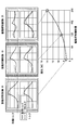
- FIG. 2 is a diagram illustrating the relationship between the amplitude of the excitation torque and the vibration amplitude of the compressor at each rotation speed of the motor (18, 28, 40, 47, 57 rps).
- rps is an abbreviation for rotation per second, and is a unit representing the number of times the rotation of the motor is repeated in one second. rps is also written as s -1.
- the specific numerical values shown in FIG. 2 and the like are merely examples, and the technique of the present disclosure does not have to be limited to these numerical values.
- the vibration amplitude of the compressor it is preferable to control the vibration amplitude of the compressor to a constant level (300 ⁇ m in the case of FIG. 2) in terms of both suppressing the vibration of the compressor and suppressing the decrease in efficiency.
- the amplitude of the excitation torque that controls the vibration amplitude of the compressor to a substantially constant level differs depending on the rotation speed (rotation speed) of the motor.
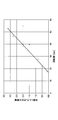
- FIG. 3 is a diagram illustrating the relationship between the rotation speed of the motor and the amplitude of the excitation torque in order to control the vibration amplitude of the compressor to a substantially constant level.
- the vibration amplitude of the compressor can be controlled to a substantially constant level by executing the vibration suppression control that changes the amplitude value of the excitation torque to the amplitude value corresponding to the rotation speed of the motor based on the relationship shown in FIG.
- the command value of the excitation torque corresponding to the rotation speed of the motor is derived based on the table showing the approximate straight line (approximate curve) shown in FIG. 3, and the motor torque is adjusted according to the operation amount corresponding to the derived command value. To do.
- the vibration amplitude of the compressor is controlled to a substantially constant level regardless of changes in the load received by the motor and the rotation speed of the motor. It is possible to suppress the vibration of the compressor and suppress the decrease in efficiency in the operating area.
- the specific operating area represents, for example, an area determined by at least one of a predetermined load fluctuation region in which the load received by the motor can fluctuate and a predetermined rotation speed region in which the rotation speed of the motor can fluctuate.
- the specific operating area may be appropriately set according to the region in which vibration suppression of the compressor and suppression of efficiency reduction are desired to be realized.
- variable that increases or decreases according to the vibration amplitude of the compressor is not limited to the excitation torque, and may be the magnitude of the fluctuation of the magnetic pole position of the motor or the magnitude of the fluctuation of the rotation speed of the motor.
- the magnitude of fluctuation represents the difference (amount of fluctuation) between the maximum value and the minimum value.
- the magnitude of the fluctuation of the magnetic pole position (or the magnitude of the fluctuation of the rotation speed) that controls the vibration amplitude of the compressor to a substantially constant level differs depending on the rotation speed of the motor. .. That is, the excitation torque on the vertical axis of FIG. 3 can be replaced with the magnitude of the fluctuation of the magnetic pole position or the magnitude of the fluctuation of the rotation speed.
- the fluctuation of the magnetic pole position is set to a value according to the rotation speed of the motor.
- the vibration amplitude of the compressor can be controlled to a substantially constant level.
- the rotation speed fluctuates to a value according to the motor rotation speed based on the relationship between the rotation speed of the motor and the magnitude of the fluctuation of the rotation speed in order to control the vibration amplitude of the compressor to a substantially constant level.
- FIG. 4 is a diagram for explaining the compressor control method in the first embodiment.
- the compressor control method in the first embodiment controls the vibration amplitude of the compressor to the first level in a specific operating area regardless of the load received by the motor and the change in the rotation speed of the motor. As a result, it is possible to suppress the vibration of the compressor and suppress the decrease in efficiency in a specific operation area.
- the compressor control method in the first embodiment is, for example, when the compressor is operating in the first operation area determined by the load received by the motor and the rotation speed of the motor, the load received by the motor and the rotation speed of the motor are determined. Regardless of the change, the vibration amplitude of the compressor is controlled to the first level.
- the compressor control method in the first embodiment sets the vibration amplitude of the compressor to the first level when the compressor is operating in the second operation area where the vibration amplitude of the compressor is smaller than that of the first operation area. Prohibit control. As a result, it is possible to suppress the deterioration of vibration caused by controlling (increasing) the vibration amplitude of the compressor to the first level in the second operating area.
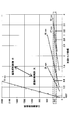
- FIG. 5 is a diagram for explaining the compressor control method in the second embodiment.
- the compressor control method in the second embodiment compresses when the load received by the motor drops below the first threshold value (composed of threshold values L1a, L2a, and L3a in the case of FIG. 5) set for each rotation speed of the motor. It has a first mode that controls the vibration amplitude of the machine to the first level.
- the compressor control method of the second embodiment when the load received by the motor rises above the second threshold value (composed of the threshold values L1b, L2b, L3b in the case of FIG. 5) set for each rotation speed of the motor. , Has a second mode of controlling the vibration amplitude of the compressor to a second level lower than the first level.
- the first threshold is set to be equal to or lower than the second threshold.
- the vibration amplitude of the compressor tends to increase.
- the vibration amplitude of the compressor is controlled to the second level lower than the first level, so that the compressor It is possible to suppress an increase in the vibration amplitude of.
- the threshold values L2a and L2b set in the rotation speed regions from R1 to R2, the threshold values L1a and L1b set in the rotation speed regions from R2 to R3, and the rotation speed regions from R3 to R4 are shown.
- the threshold values L3a and L3b to be set are illustrated.
- the number of threshold values and the magnitude relationship between a plurality of threshold values are arbitrary and may be set as appropriate.
- the threshold value L1a is lower than the threshold value L1b
- the threshold value L2a is lower than the threshold value L2b
- the threshold value L3a is lower than the threshold value L3b.
- the vibration amplitude of the compressor is allowed to be at the first level higher than the second level. , The degree of vibration suppression is relaxed. Therefore, in the operating area where the load received by the motor is equal to or less than the first threshold value, the efficiency of the compressor or the like is increased as compared with the operating area where the load received by the motor is larger than the second threshold value while suppressing the vibration amplitude of the compressor. be able to.
- a predetermined threshold value L for example, the first threshold value
- a predetermined threshold value L for example, the first threshold value
- JIS Japanese Industrial Standards
- the eight capacities defined in JIS B8616: 2015 rated cooling standard capacity, intermediate cooling standard capacity, intermediate cooling medium temperature capacity, minimum cooling medium temperature capacity, rated heating standard capacity, intermediate heating standard capacity, minimum heating. It is preferable that at least one of the standard capacity and the maximum heating / low temperature capacity) is set in an operating area where the load received by the motor is equal to or less than a predetermined threshold L.
- FIG. 6 is a diagram for explaining the compressor control method in the third embodiment.
- the compressor control method in the third embodiment has a third mode in which the vibration amplitude of the compressor is controlled between the first level and the second level. According to the compressor control method in the third embodiment, even if the vibration amplitude of the compressor cannot be controlled to the second level by some factor (for example, the limitation on the hardware of the inverter), the vibration amplitude of the compressor is the second. Since it is controlled between the first level and the second level, the vibration of the compressor can be suppressed.
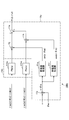
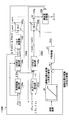
- FIG. 7 is a block diagram illustrating the configuration of the motor control device and its peripheral devices.
- the motor control device 1 shown in FIG. 7 controls a synchronous motor 3 which is an example of a motor for driving a compressor, which is a device for compressing a refrigerant.
- the synchronous motor 3 is a three-phase rotary motor, and includes an armature and a rotor that is a field magnet (both not shown).
- the armature has an armature winding, and the rotor rotates relative to the armature.
- the field magnet includes, for example, a magnet (field magnet: not shown) that generates a field magnetic flux, and for example, an embedded magnet type is adopted.
- the voltage supply source 2 includes, for example, a voltage-controlled inverter and its control unit, and synchronizes a three-phase voltage with a three-phase voltage based on a three-phase voltage command value [V *] (the symbol [] indicates a vector). Apply to 3. As a result, the three-phase current [I] flows from the voltage supply source 2 to the synchronous motor 3.
- the motor control device 1 controls the primary magnetic flux and the rotation speed (rotation angular velocity in the following example) of the synchronous motor 3.
- the primary magnetic flux is an electric flux generated by the field magnetic flux ⁇ 0 generated by the field magnet and the armature current (which is also the three-phase current [I]) flowing in the synchronous motor 3 (more specifically, in the armature). It is a combination with the magnetic flux of the armature reaction.
- the primary magnetic flux command ⁇ * is a command value of the actual magnitude of the primary magnetic flux ⁇ .
- the motor control device 1 controls the synchronous motor 3 by controlling a method of matching the primary magnetic flux of the synchronous motor 3 with the primary magnetic flux command ⁇ * on the ⁇ c axis which is the control axis of the primary magnetic flux.
- the ⁇ c axis advances with a predetermined phase difference with respect to the d axis indicating the phase of the field magnetic flux ⁇ 0 in the rotating coordinate system.
- the actual primary magnetic flux has a ⁇ c axis component ⁇ c on the ⁇ c axis and a ⁇ c axis component ⁇ c on the ⁇ c axis.
- the ⁇ c axis advances with respect to the ⁇ c axis at an electric angle of 90 degrees.
- the expressions of primary magnetic fluxes ⁇ c and ⁇ c may be simply used.
- the command value of the primary magnetic flux has a ⁇ c-axis component of zero, and the ⁇ c-axis component is set to the primary magnetic flux command ⁇ * as described above. That is, the motor control device 1 controls to make the ⁇ c axis component ⁇ c of the actual primary magnetic flux zero, and obtains a predetermined phase difference.
- Such control is commonly referred to as primary magnetic flux control and is known.
- the primary magnetic flux and the rotation speed are adopted as the controllable amount in the primary magnetic flux control.
- the primary magnetic flux may be an estimated value or an observed value. Techniques for estimating the primary magnetic flux are also known.
- the motor control device 1 includes a first coordinate conversion unit 101, a magnetic flux control unit 102, a second coordinate conversion unit 104, and a speed command correction device 12.
- the functions of each of these parts included in the motor control device 1 are realized by operating a processor (for example, a CPU (Central Processing Unit)) by a program readable and stored in a memory.
- a processor for example, a CPU (Central Processing Unit)
- the first coordinate conversion unit 101 performs three-phase / two-phase conversion based on the electric angle ⁇ e of the synchronous motor 3 obtained as described later. Specifically, the three-phase current [I] is converted into the ⁇ c-axis current i ⁇ c and the ⁇ c-axis current i ⁇ c in the ⁇ c- ⁇ c rotating coordinate system that controls the primary magnetic flux. At this time, since the sum of the three phases of the three-phase current becomes zero, if the two phases are obtained, the other one phase is estimated from the two phases. “3 (2)” in FIG. 7 indicates that the detected current may be for three phases or for two phases. It can be said that the ⁇ c-axis current i ⁇ c and the ⁇ c-axis current i ⁇ c are the ⁇ c-axis component and the ⁇ c-axis component of the current flowing through the synchronous motor 3, respectively.
- the second coordinate conversion unit 104 performs two-phase / three-phase conversion based on the electric angle ⁇ e. Specifically, the ⁇ c-axis voltage command value v ⁇ * and the ⁇ c-axis voltage command value v ⁇ * in the ⁇ c- ⁇ c rotating coordinate system are converted into a three-phase voltage command value [V *].
- the voltage command value in another coordinate system is changed to the ⁇ c axis voltage command value v ⁇ * and the ⁇ c axis voltage command value v ⁇ *. May be converted.
- an ⁇ fixed coordinate system, an uvw fixed coordinate system, and a polar coordinate system can be adopted.
- the magnetic flux control unit 102 obtains the corresponding rotation speed command ⁇ m * (for the mechanical angle) from the rotation speed command ⁇ eo * (for the electric angle). Since such a function can be easily realized by a known technique, the details thereof will be omitted.
- the magnetic flux control unit 102 has, for example, an integration function. With the integration function, the rotation speed command ⁇ e * is integrated to obtain the electric angle ⁇ e. From the obtained electric angle ⁇ e and the load angle ⁇ of the primary magnetic flux with respect to the d-axis, the rotation angle ⁇ m as the mechanical angle can be obtained by the equation (1). However, the pole logarithm P of the synchronous motor 3 was introduced.
- the load angle ⁇ may be an estimated value or an observed value.
- Techniques for estimating the load angle ⁇ are known. Further, as a method for obtaining the rotation angle ⁇ m, a known technique other than the equation (1) can be adopted.
- the magnetic flux control unit 102 has a ⁇ c axis voltage command value v ⁇ * and a ⁇ c axis voltage command value based on the ⁇ c axis current i ⁇ c, the ⁇ c axis current i ⁇ c, the primary magnetic flux ⁇ c, ⁇ c, the primary magnetic flux command ⁇ *, and the rotation speed command ⁇ e *. Generate v ⁇ *. Since such a function, a configuration for realizing the function, and a method for estimating the primary magnetic fluxes ⁇ c and ⁇ c are known, the details thereof will be omitted here.
- the speed command correction device 12 includes a ⁇ c-axis current correction unit 105 (described as “i ⁇ c correction unit” in FIG. 7), an adder 107, a subtractor 109, and a high-pass filter 110.
- the ⁇ c-axis current correction unit 105 has a first ⁇ c-axis current correction value ⁇ i ⁇ c1 based on the rotation angle ⁇ m, the rotation speed command ⁇ m *, the primary magnetic flux ⁇ c, ⁇ c, the ⁇ c-axis current i ⁇ c, the ⁇ c-axis current i ⁇ c, and the order n. Ask for.
- the first ⁇ c-axis current correction value ⁇ i ⁇ c1 is an amount that reduces the nth-order component (n is a positive integer) of the fundamental frequency of the rotation angle ⁇ m, and its specific significance and method of obtaining it will be described later.
- the adder 107 adds the first ⁇ c-axis current correction value ⁇ i ⁇ c1 to the ⁇ c-axis current i ⁇ c to obtain the first corrected ⁇ c-axis current i ⁇ c1.
- the high-pass filter 110 functions as a DC component removing unit that removes the DC component from the first corrected ⁇ c axis current i ⁇ c1 to obtain the angular velocity correction amount ⁇ e *.
- the speed command correction device 12 may further include a constant multiple portion 108, and the angular velocity correction amount ⁇ e * may be obtained assuming that the output of the high-pass filter 110 is multiplied by a predetermined gain Km by the constant multiple portion 108.
- the subtractor 109 subtracts the angular velocity correction amount ⁇ e * from the rotation speed command ⁇ eo * for the electric angle to obtain the corrected rotation speed command ⁇ e *.
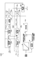
- FIG. 8 is a block diagram showing a first configuration example of the ⁇ c-axis current correction unit according to the first embodiment.
- the ⁇ c-axis current correction unit 1105A shown in FIG. 8 is an example of the ⁇ c-axis current correction unit 105 (see FIG. 7).
- the ⁇ c-axis current correction unit 1105A includes a vibration excitation torque extraction unit 105A, an output torque extraction unit 105B, an adder 105g, and a correction amount calculation unit 105h.
- the excitation torque extraction unit 105A has an angular pulsation extraction unit 105a, an nth-order component extraction unit 105b, a torque conversion unit 105i, and a proportional division coefficient multiplication unit 105c.
- the angle pulsation extraction unit 105a obtains the rotation angle difference ⁇ m from the rotation angle ⁇ m and the rotation speed command ⁇ m *.
- the rotation angle difference ⁇ m represents the pulsation of the rotation angle ⁇ m with respect to the rotation angle ⁇ m at the time of constant speed rotation of the synchronous motor 3.
- the nth-order component extraction unit 105b extracts the nth-order components ⁇ ms (n) and ⁇ mc (n) of the fundamental frequency of the rotation angle ⁇ m from the rotation angle difference ⁇ m.
- the nth-order component extraction unit 105b handles the component of the rotation angle difference ⁇ m of the order to be extracted separately as a sine value component ⁇ ms (n) and a cosine value component ⁇ mc (n).
- the specific operation of the nth-order component extraction unit 105b will be described later.
- the torque conversion unit 105i converts the nth-order components ⁇ ms (n) and ⁇ mc (n) into torque. Specifically, the nth-order components ⁇ vs (n) and ⁇ vc (n) of the estimated value of the excitation torque ⁇ v of the synchronous motor 3 at the rotation angle ⁇ m are obtained. For example, the torque conversion unit 105i squares the moment of inertia J of the mechanical load, the rotation speed command ⁇ m *, and the square of the order n with respect to the nth-order components ⁇ ms (n) and ⁇ mc (n) of the rotation angle difference ⁇ m.
- the nth-order component of the excitation torque ⁇ v is obtained. Specifically, the nth-order sine value component ⁇ vs (n) and the cosine value component ⁇ vc (n) of the excitation torque ⁇ v are obtained.
- the excitation torque ⁇ v is a value obtained by subtracting the load torque ⁇ d of the mechanical load (not shown) driven by the synchronous motor 3 from the output torque ⁇ e of the synchronous motor 3.
- the load torque ⁇ d has periodicity, that is, the synchronous motor 3 drives the periodic load.
- a compression mechanism compressor for compressing a refrigerant used in an air conditioner can be mentioned.
- the excitation torque ⁇ v has a component (the above-mentioned “nth-order component”) that fluctuates in a period of 1 / n of the period of the rotation angle ⁇ m, and has an independent amplitude for each order.
- the mechanical load is a 2-cylinder compressor
- the output torque extraction unit 105B includes an output torque estimation unit 105d, an nth-order component extraction unit 105e, and an apportionment coefficient multiplication unit 105f.
- the output torque estimation unit 105d uses the primary magnetic fluxes ⁇ c and ⁇ c and the ⁇ c axis currents i ⁇ c and ⁇ c axis currents i ⁇ c to obtain the estimated value of the output torque ⁇ e by the equation (7).
- the nth-order component extraction unit 105e extracts the nth-order components ⁇ es (n) and ⁇ ec (n) of the fundamental frequency of the rotation angle ⁇ m from the output torque ⁇ e in the same manner as the nth-order component extraction unit 105b.
- the nth-order component extraction units 105b and 105e both obtain the input amount of the sine value component and the cosine value component by using the Fourier transform.
- the rotation angle difference ⁇ m and the output torque ⁇ e are both functions of the rotation angle ⁇ m, and when both of them are expressed as the function F ( ⁇ m), the equation (8) is established.
- the value a0 is the DC component (0th order component) of the function F ( ⁇ m)
- the value an is the amplitude of the cosine value of the nth order component of the function F ( ⁇ m)
- the value bn is the function F. It is the amplitude of the sine value of the nth-order component of ( ⁇ m).
- the order n and the angle of rotation ⁇ m are input to the nth-order component extraction units 105b and 105e.
- the time t may be adopted as the integration variable instead of the rotation angle ⁇ m.
- ⁇ ma represents the average value of the angular velocity (average angular velocity).
- the nth-order component extraction unit 105b adopts the rotation angle difference ⁇ m as a function F ( ⁇ m), outputs the value bn as the sine value component ⁇ ms (n) of the rotation angle difference ⁇ m, and outputs the value an as the cosine of the rotation angle difference ⁇ m. It is output as a value component ⁇ mc (n).
- the nth-order component extraction unit 105e adopts the output torque ⁇ e as a function F ( ⁇ m), outputs the value bn as the sinusoidal value component ⁇ es (n) of the output torque ⁇ e, and outputs the value an as the cosine value component ⁇ ec of the output torque ⁇ e. Output as (n).
- the apportionment coefficient multiplication unit 105c multiplies the apportionment coefficient K (n) set for each degree n by both the sinusoidal value component ⁇ vs (n) and the cosine value component ⁇ vc (n).
- the proportional division coefficient multiplication unit 105f multiplies the proportional division coefficient [1-K (n)] by both the sinusoidal value component ⁇ es (n) and the cosine value component ⁇ ec (n). However, 0 ⁇ K (n) ⁇ 1 is established for each of the orders n.
- the apportionment coefficient multiplication units 105c and 105f proportionally divide the sine value component ⁇ vs (n) and the sine value component ⁇ es (n) by a predetermined apportionment ratio K (n) / [1-K (n)]. It functions as an apportionment unit for apportioning the cosine value component ⁇ vc (n) and the cosine value component ⁇ ec (n) by the apportionment ratio.
- the proportional division coefficients K (n) and [1-K (n)] may be externally given to the proportional division coefficient multiplication units 105c and 105f. In this case, the apportionment coefficient multiplication units 105c and 105f are realized by a simple multiplier.
- the adder 105g adds the products ⁇ vs (n) ⁇ K (n), ⁇ es (n) ⁇ [1-K (n)] related to the sine value component for each degree n, and the product ⁇ vc (related to the cosine value component). n) ⁇ K (n), ⁇ ec (n) ⁇ [1-K (n)] are added together, and the sum of the pair is output.
- nth component extraction units 105b and 105e a plurality of orders n to be extracted may be adopted.
- the adder 105g has a pair of sums ⁇ vs (1) ⁇ K (1) + ⁇ es (1) ⁇ [1-K (1)], ⁇ vc (1) ⁇ . K (1) + ⁇ ec (1) ⁇ [1-K (1)] is output.
- the adder 105g has the sum ⁇ vs (1) ⁇ K (1) + ⁇ es (1) ⁇ [1-K (1)], ⁇ vc ( 1) ⁇ K (1) + ⁇ ec (1) ⁇ [1-K (1)] pair and sum ⁇ vs (2) ⁇ K (2) + ⁇ es (2) ⁇ [1-K (2)], ⁇ vc ( 2) Outputs two pairs of K (2) + ⁇ ec (2) and [1-K (2)].
- the slant "/" attached to the arrow in FIG. 8 indicates such a pair of input / output.
- the adder 105g can output paired values ⁇ es (n) -K (n) ⁇ ds (n) and ⁇ ec (n) -K (n) ⁇ dc (n).
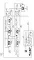
- FIG. 9 is a block diagram illustrating the configuration of the correction amount calculation unit 105h.
- the correction amount calculation unit 105h has a PI control unit 11h and a composite value calculation unit 11y.
- a case where the order n is 1 is illustrated.
- the PI control unit 11h includes PI controllers 11hs and 11hc that perform proportional integration control.
- the PI controller 11hs performs proportional integral control for the value related to the sinusoidal value component.
- the PI controller 11hc performs proportional integral control for the value related to the cosine value component.
- the PI controller 11hs inputs the values ⁇ es (n) -K (n) and ⁇ ds (n), and outputs the result of performing proportional integration control with respect to the values ⁇ es (n) -K (n) and ⁇ ds (n).
- the PI controller 11hc inputs the values ⁇ ec (n) ⁇ K (n) ⁇ ⁇ dc (n) and outputs the result of performing proportional integration control with respect to the values ⁇ ec (n) ⁇ K (n) ⁇ ⁇ dc (n).
- the composite value calculation unit 11y synthesizes the result of the proportional integration control for the sinusoidal value component obtained by the PI controller 11hs and the result of the proportional integration control for the cosine value component obtained by the PI controller 11hc as follows. To find the composite value.
- the composite value calculation unit 11y has a multiplier 11j, 11k, 11p, a sine value generation unit 11q, a cosine value generation unit 11r, and an adder 11s.
- the multiplier 11p inputs the degree n and the rotation angle ⁇ m, and obtains the product n ⁇ ⁇ m of both.
- the sine value generation unit 11q inputs the product n ⁇ ⁇ m and obtains the sine value sin (n ⁇ ⁇ m).
- the cosine value generation unit 11r inputs the product n ⁇ ⁇ m and obtains the cosine value cos (n ⁇ ⁇ m).
- the multiplier 11j obtains the product of the result obtained by the PI controller 11hs and the sine value sin (n ⁇ ⁇ m).
- the multiplier 11k obtains the product of the result obtained by the PI controller 11hc and the cosine value cos (n ⁇ ⁇ m).
- the adder 11s synthesizes trigonometric functions to obtain a composite value. Specifically, the adder 11s obtains a composite value as the sum of the product obtained by the multiplier 11j and the product obtained by the multiplier 11k.
- the combined value is output from the combined value calculation unit 11y as the first ⁇ c-axis current correction value ⁇ i ⁇ c1. This corresponds to using the results obtained by the PI controllers 11hs and 11hc as the coefficients of the Fourier series and obtaining the first ⁇ c-axis current correction value ⁇ i ⁇ c1 from the results of the Fourier series.
- the first ⁇ c-axis current correction value ⁇ i ⁇ c1 obtained based on the nth-order component of the excitation torque ⁇ v and the output torque ⁇ e is reflected in the ⁇ c-axis current i ⁇ c by the adder 107 (see FIG. 7).
- the rotation speed command ⁇ eo * is corrected in the direction of increasing in accordance with the increase in the excitation torque ⁇ v and / or the increase in the output torque ⁇ e.
- the corrected rotation speed command ⁇ e * is added. It is controlled so as to suppress the pulsation of the vibration torque ⁇ v and the output torque ⁇ e.
- the impact on is apportioned. This is preferable from the viewpoint that the proportional division ratio can be maintained regardless of the gain of the proportional integral control, and also from the viewpoint that the frequency band corresponding to the rotation speed of the mechanical angle is not required in the proportional integral control.
- the correction amount calculation unit 105h provides a PI control unit 11h and a composite value calculation unit 11y excluding the adder 11s for each order. Then, the adder 11s adds all the outputs of the composite value calculation unit 11y provided for each order and outputs the first ⁇ c-axis current correction value ⁇ i ⁇ c1.
- the proportional division coefficient K (n) is 1 in a certain degree n.
- the output of the proportional division coefficient multiplication unit 105f becomes 0, the output torque ⁇ e does not contribute to the first ⁇ c axis current correction value ⁇ i ⁇ c1, and only the excitation torque ⁇ v contributes to the correction of the rotation speed command ⁇ eo *.
- the correction of the rotation speed command ⁇ eo * exclusively contributes to the suppression of the excitation torque ⁇ v.
- the proportional division coefficient K (n) is 0 in a certain degree n.
- the output of the proportional division coefficient multiplication unit 105c becomes 0, the excitation torque ⁇ v does not contribute to the first ⁇ c axis current correction value ⁇ i ⁇ c1, and only the output torque ⁇ e contributes to the correction of the rotation speed command ⁇ eo *.
- the correction of the rotation speed command ⁇ eo * exclusively contributes to the suppression of the pulsation of the output torque ⁇ e, and makes it easier to keep the amplitude of the current [I] constant.
- the ⁇ c-axis current correction unit 105 may be configured by omitting the adder 105g, the output torque extraction unit 105B, and the proportional division coefficient multiplication unit 105c.
- the sine value component ⁇ vs (n) and the cosine value component ⁇ vc (n) are used (more specifically, proportional to them) without using the sine value component ⁇ es (n) and the cosine value component ⁇ ec (n).
- the correction amount calculation unit 105h obtains the first ⁇ c-axis current correction value ⁇ i ⁇ c1. Even with such a configuration, the excitation torque ⁇ v can be suppressed by correcting the rotation speed command ⁇ eo *.
- the ⁇ c-axis current correction unit 105 may be configured by omitting the adder 105g, the excitation torque extraction unit 105A, and the proportional division coefficient multiplication unit 105f.
- the sine value component ⁇ vs (n) and the cosine value component ⁇ vc (n) are not used, but the sine value component ⁇ es (n) and the cosine value component ⁇ ec (n) are used (more specifically, proportional to these).
- the correction amount calculation unit 105h obtains the first ⁇ c-axis current correction value ⁇ i ⁇ c1. Even with such a configuration, the pulsation of the output torque ⁇ e can be suppressed by correcting the rotation speed command ⁇ eo *.
- the amount of vibration suppression of the compressor can be controlled by adjusting the magnitude of the proportional division coefficient K (n).
- the ⁇ c-axis current correction unit 1105A determines the nth-order component (vibration torque command) of the command value of the vibration torque according to the detected value or the command value of the rotation speed of the synchronous motor 3. Then, the ⁇ c-axis current correction unit 1105A determines the magnitude of the proportional division coefficient K (n) that controls the vibration amplitude of the compressor to a substantially constant level in response to the determined excitation torque command.
- the ⁇ c-axis current correction unit 1105A has a table 23, a subtractor 22, and a PI controller 21.
- the relationship between the rotational speed of the synchronous motor 3 and the exciting torque for controlling the vibration amplitude of the compressor to a substantially constant level in a specific operating area is preset.
- the table 23 corresponds to a table representing an approximate straight line (approximate curve) shown in FIG. 3 described above.
- Table 23 is defined by a regression equation or map data representing an approximate curve.
- the ⁇ c-axis current correction unit 1105A determines the excitation torque command for controlling the vibration amplitude of the compressor to a substantially constant level according to the detected value or the command value of the rotational speed of the synchronous motor 3 based on the table 23.
- This excitation torque command is an example of data read from a preset table. By using a preset table, the load of arithmetic processing can be reduced.
- the subtractor 22 calculates the error between the nth-order component of the command value of the excitation torque and the nth-order component of the estimated value of the excitation torque.
- the nth-order component of the estimated value of the excitation torque is, for example, a sine value component ⁇ vs (n) and a cosine value component ⁇ vc (n).
- the PI controller 21 derives an apportionment coefficient K (n) that brings the error calculated by the subtractor 22 close to zero by PI control.
- the apportionment coefficient K (n) may be calculated by PID control.
- P stands for proportionality
- I stands for integral
- D stands for derivative.
- the vibration amplitude of the compressor is substantially constant in a specific operating area regardless of the load received by the synchronous motor 3 and the change in the rotation speed of the synchronous motor 3. Controlled by level. Therefore, it is possible to suppress the vibration of the compressor and suppress the decrease in efficiency in a specific operation area.
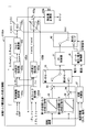
- FIG. 10 is a block diagram showing a second configuration example of the ⁇ c-axis current correction unit in the first embodiment.
- the ⁇ c-axis current correction unit 1105B shown in FIG. 10 is an example of the ⁇ c-axis current correction unit 105 (see FIG. 7).
- the description of the same configuration as that of the first configuration example (FIG. 8) in the second configuration example (FIG. 10) will be omitted by referring to the above description.
- the ⁇ c-axis current correction unit 1105B sets the nth-order component (magnetic pole position fluctuation amount command) of the command value of the magnitude of fluctuation of the magnetic pole position of the synchronous motor 3 according to the detected value or the command value of the rotation speed of the synchronous motor 3. decide. Then, the ⁇ c-axis current correction unit 1105B determines the magnitude of the proportional division coefficient K (n) that controls the vibration amplitude of the compressor to a substantially constant level in response to the determined magnetic pole position fluctuation amount command.
- the ⁇ c-axis current correction unit 1105B has a table 24, a subtractor 22, and a PI controller 21.
- the relationship between the rotation speed of the synchronous motor 3 and the magnitude of fluctuation in the magnetic pole position for controlling the vibration amplitude of the compressor to a substantially constant level in a specific operating area is preset. ..
- the table 24 corresponds to a table representing an approximate straight line (approximate curve) shown in FIG. 3 described above. Table 24 is defined by a regression equation or map data representing an approximate curve.
- the ⁇ c-axis current correction unit 1105B determines the magnetic pole position fluctuation amount command for controlling the vibration amplitude of the compressor to a substantially constant level according to the detected value or the command value of the rotational speed of the synchronous motor 3 based on the table 24.
- This magnetic pole position fluctuation amount command is an example of data read from a preset table.
- the subtractor 22 calculates the error between the nth-order component of the command value of the magnitude of fluctuation of the magnetic pole position and the nth-order component of the estimated value of the magnitude of fluctuation of the magnetic pole position.
- the nth-order component of the estimated value of the fluctuation of the magnetic pole position is, for example, a sine value component ⁇ ms (n) and a cosine value component ⁇ mc (n).
- the PI controller 21 derives an apportionment coefficient K (n) that brings the error calculated by the subtractor 22 close to zero by PI control or the like. By deriving the proportional division coefficient K (n) in this way, it is possible to suppress the vibration of the compressor and suppress the decrease in efficiency in a specific operating area, as in the above-described configuration example.
- FIG. 11 is a block diagram showing a third configuration example of the ⁇ c-axis current correction unit according to the first embodiment.
- the ⁇ c-axis current correction unit 1105C shown in FIG. 11 is an example of the ⁇ c-axis current correction unit 105 (see FIG. 7).
- the description of the same configuration as that of the first configuration example (FIG. 8) in the third configuration example (FIG. 11) will be omitted by referring to the above description.
- the ⁇ c-axis current correction unit 1105C sets the nth-order component (rotational speed fluctuation amount command) of the command value of the magnitude of the fluctuation of the rotational speed of the synchronous motor 3 according to the detected value or the command value of the rotational speed of the synchronous motor 3. decide. Then, the ⁇ c-axis current correction unit 1105C determines the magnitude of the proportional division coefficient K (n) that controls the vibration amplitude of the compressor to a substantially constant level in response to the determined rotation speed fluctuation amount command.
- the ⁇ c-axis current correction unit 1105C has a table 25, an nth-order component extraction unit 26, a subtractor 22, and a PI controller 21.
- the relationship between the rotation speed of the synchronous motor 3 and the magnitude of fluctuation of the rotation speed for controlling the vibration amplitude of the compressor to a substantially constant level in a specific operation area is preset. ..
- the table 25 corresponds to a table representing an approximate straight line (approximate curve) shown in FIG. 3 described above.
- Table 25 is defined by a regression equation or map data representing an approximate curve.
- the ⁇ c-axis current correction unit 1105C determines the rotation speed fluctuation amount command for controlling the vibration amplitude of the compressor to a substantially constant level according to the detected value or the command value of the rotation speed of the synchronous motor 3 based on the table 25.
- This rotation speed fluctuation amount command is an example of data read from a preset table.
- the nth-order component extraction unit 26 extracts the nth-order component of the estimated value of the fluctuation of the rotation speed based on the detected value or the command value of the rotation speed of the synchronous motor 3.
- the subtractor 22 calculates an error between the nth-order component of the command value of the magnitude of the fluctuation of the rotational speed and the nth-order component of the estimated value of the magnitude of the fluctuation of the rotational speed.
- the PI controller 21 derives an apportionment coefficient K (n) that brings the error calculated by the subtractor 22 close to zero by PI control or the like. By deriving the proportional division coefficient K (n) in this way, it is possible to suppress the vibration of the compressor and suppress the decrease in efficiency in a specific operating area, as in the above-described configuration example.
- FIG. 12 is a block diagram showing a fourth configuration example of the ⁇ c-axis current correction unit according to the first embodiment.
- the ⁇ c-axis current correction unit 1105D shown in FIG. 12 is an example of the ⁇ c-axis current correction unit 105 (see FIG. 7).
- the description of the same configuration as that of the first configuration example (FIG. 8) in the fourth configuration example (FIG. 12) will be omitted by referring to the above description.
- the ⁇ c-axis current correction unit 1105D sets in the table 27 the magnitude of the proportional division coefficient K (n) that controls the vibration amplitude of the compressor to a substantially constant level according to the detected value or the command value of the rotational speed of the synchronous motor 3. Determine based on.
- the ⁇ c-axis current correction unit 1105D has a table 27.
- the relationship between the rotation speed of the synchronous motor 3 and the excitation torque and the proportional division coefficient K (n) for controlling the vibration amplitude of the compressor to a substantially constant level in a specific operating area is preset. It is a thing.
- the table 27 corresponds to a table obtained by combining the table representing the approximate straight line (approximate curve) shown in FIG. 3 with the proportional division coefficient K (n).
- Table 27 is defined by a regression equation or map data representing an approximate curve. If the vibration torque is controlled according to the command value of the vibration torque with respect to the rotation speed shown in FIG. 3, the vibration amplitude can be controlled to a substantially constant level regardless of the load received by the motor and the change in the rotation speed of the motor. Therefore, in the embodiment shown in FIG.
- the detected value or command value of the rotational speed of the synchronous motor 3 and the nth-order component of the estimated value of the excitation torque are input to the table 27, and the operation amount is output from the table 27.
- the configuration is adopted.
- the operation amount is the proportional division coefficient K (n), and the motor torque is adjusted according to the proportional division coefficient K (n).
- the excitation torque on the vertical axis of FIG. 3 can be replaced with the magnitude of the fluctuation of the magnetic pole position or the magnitude of the fluctuation of the rotation speed, but in this embodiment, the vibration is more desirable. Torque is used.
- the ⁇ c-axis current correction unit 1105D apportionably controls the vibration amplitude of the compressor to a substantially constant level according to the detected value or command value of the rotational speed of the synchronous motor 3 and the nth-order component of the estimated value of the excitation torque.
- the coefficient K (n) is determined based on the table 27.
- the apportionment coefficient K (n) is an example of data read from a preset table. By deriving the proportional division coefficient K (n) in this way, it is possible to suppress the vibration of the compressor and suppress the decrease in efficiency in a specific operating area, as in the above-described configuration example.
- the exciting torque may be replaced by the magnitude of the fluctuation of the magnetic pole position or the magnitude of the fluctuation of the rotation speed. Even in this case, by deriving the proportional division coefficient K (n) using the table 27, it is possible to suppress the vibration of the compressor and suppress the decrease in efficiency in a specific operating area.
- FIG. 13 is a block diagram showing a first configuration example of the ⁇ c-axis current correction unit in the second embodiment.
- the ⁇ c-axis current correction unit 2105A shown in FIG. 13 is an example of the ⁇ c-axis current correction unit 105 (see FIG. 7).
- the description of the same configuration as the first configuration example (FIG. 8) of the first embodiment can be described by referring to the above description. Omit.
- the ⁇ c-axis current correction unit 2105A is the nth-order component (first vibration torque command) of the command value of the vibration torque in the above-mentioned first mode according to the detected value or the command value of the rotation speed of the synchronous motor 3. Is determined based on the table 35. Similarly, the ⁇ c-axis current correction unit 2105A receives the nth-order component (second excitation) of the command value of the excitation torque in the above-mentioned second mode according to the detected value or the command value of the rotation speed of the synchronous motor 3. The torque command) is determined based on the table 36.
- the ⁇ c-axis current correction unit 2105A has tables 35 and 36, subtractors 33 and 34, a switching unit 32, a switching determination unit 37, and a PI controller 31.
- the relationship between the rotational speed of the synchronous motor 3 and the exciting torque for controlling the vibration amplitude of the compressor to the first level in a specific operating area in the first mode is preset. is there.
- the ⁇ c-axis current correction unit 2105A determines the first excitation torque command for controlling the vibration amplitude of the compressor to the first level according to the detected value or the command value of the rotational speed of the synchronous motor 3 based on the table 35. ..
- the relationship between the rotational speed of the synchronous motor 3 and the exciting torque for controlling the vibration amplitude of the compressor to the second level in a specific operating area in the second mode is preset. is there.
- the ⁇ c-axis current correction unit 2105A determines a second excitation torque command for controlling the vibration amplitude of the compressor to the second level according to the detected value or the command value of the rotational speed of the synchronous motor 3 based on the table 36. ..
- the subtractor 33 calculates the first error between the nth-order component of the command value of the excitation torque and the nth-order component of the estimated value of the excitation torque in the first mode.
- the subtractor 34 calculates the second error between the nth-order component of the command value of the excitation torque and the nth-order component of the estimated value of the excitation torque in the second mode.
- the switching unit 32 switches the error input to the PI controller 31 to the first error or the second error according to the determination result by the switching determination unit 37.
- the switching determination unit 37 determines that the first error is input to the PI controller 31 and determines that the synchronous motor 3 is input.
- the load received by the synchronous motor 3 rises above the second threshold value set for each rotation speed of the synchronous motor 3, it is determined that the second error is input to the PI controller 31.
- the load received by the synchronous motor 3 includes, for example, pressure and temperature. Load information such as pressure and temperature is supplied from the outside of the compressor.
- the PI controller 31 derives an apportionment coefficient K (n) that brings the error input from the switching unit 32 close to zero by PI control or the like.
- K (n) an apportionment coefficient that brings the error input from the switching unit 32 close to zero by PI control or the like.
- the exciting torque may be replaced by the magnitude of the fluctuation of the magnetic pole position or the magnitude of the fluctuation of the rotation speed. Even in this case, when the load received by the synchronous motor 3 rises above the second threshold value, the vibration amplitude of the compressor is controlled to the second level lower than the first level, so that the increase in the vibration amplitude of the compressor can be suppressed. ..
- FIG. 14 is a block diagram showing a second configuration example of the ⁇ c-axis current correction unit in the second embodiment.
- the ⁇ c-axis current correction unit 2105B shown in FIG. 14 is an example of the ⁇ c-axis current correction unit 105 (see FIG. 7).
- the fourth configuration example (FIG. 12) of the first embodiment and the first configuration example (FIG. 13) of the second embodiment are described in detail below. The description of the same configuration will be omitted by referring to the above description.
- the ⁇ c-axis current correction unit 2105B determines the magnitude of the proportional division coefficient K (n) that controls the vibration amplitude of the compressor to the first level according to the detected value or the command value of the rotation speed of the synchronous motor 3 based on the table 38. To decide. Similarly, the ⁇ c-axis current correction unit 2105B tables the magnitude of the proportional division coefficient K (n) that controls the vibration amplitude of the compressor to the second level according to the detected value or the command value of the rotational speed of the synchronous motor 3. Determined based on 39.
- the ⁇ c-axis current correction unit 1105D has tables 38 and 39.
- the relationship between the rotational speed of the synchronous motor 3 and the excitation torque and the proportional division coefficient K (n) for controlling the vibration amplitude of the compressor to the first level is set in advance.
- the ⁇ c-axis current correction unit 2105A is a proportional division coefficient that controls the vibration amplitude of the compressor to the first level according to the detected value or command value of the rotational speed of the synchronous motor 3 and the nth-order component of the estimated value of the excitation torque.
- K (n) is determined based on the table 38.
- Table 39 the relationship between the rotational speed of the synchronous motor 3 and the excitation torque and the proportional division coefficient K (n) for controlling the vibration amplitude of the compressor to the second level is set in advance.
- the ⁇ c-axis current correction unit 2105A is a proportional division coefficient that controls the vibration amplitude of the compressor to the second level according to the detected value or command value of the rotational speed of the synchronous motor 3 and the nth-order component of the estimated value of the excitation torque.
- K (n) is determined based on Table 39.
- the switching unit 32 switches the proportional division coefficient K (n) to a coefficient for controlling the first level or a coefficient for controlling the second level according to the determination result by the switching determination unit 37.
- the switching determination unit 37 selects the proportional division coefficient K (n) to be controlled to the first level, and the synchronous motor 3 selects the proportional division coefficient K (n).
- the proportional division coefficient K (n) to be controlled to the second level is selected.
- the exciting torque may be replaced by the magnitude of the fluctuation of the magnetic pole position or the magnitude of the fluctuation of the rotation speed. Even in this case, when the load received by the synchronous motor 3 rises above the second threshold value, the vibration amplitude of the compressor is controlled to the second level lower than the first level, so that the increase in the vibration amplitude of the compressor can be suppressed. ..
- FIG. 15 is a block diagram showing a first configuration example of the ⁇ c-axis current correction unit according to the third embodiment.
- the ⁇ c-axis current correction unit 3105A shown in FIG. 15 is an example of the ⁇ c-axis current correction unit 105 (see FIG. 7). Similar to the first configuration example (FIG. 8) of the first embodiment and the first configuration example (FIG. 13) of the second embodiment of the first configuration example (FIG. 15) of the third embodiment. The description of the configuration of the above will be omitted by referring to the above description.
- the ⁇ c-axis current correction unit 3105A includes a control unit 41 that determines the proportional division coefficient K (n) in the above-mentioned third mode according to the voltage value applied to the synchronous motor 3 and the current value flowing through the synchronous motor 3. Have.
- the control unit 41 controls the voltage or current supplied from the inverter in the voltage supply source 2 to the synchronous motor 3 so as to suppress the vibration amplitude of the compressor to the first level or lower. For example, when it is detected that the vibration amplitude of the compressor cannot be maintained at the second level for a predetermined time or longer in the second mode, the control unit 41 suppresses the vibration amplitude of the compressor to the first level or less. (N) is generated, and the operation mode of the compressor is switched from the second mode to the third mode by the switching unit 42. The control unit 41 adjusts the proportional division coefficient K (n) so that the voltage or current supplied to the synchronous motor 3 is limited to a predetermined value or less that suppresses the vibration amplitude of the compressor to the first level or less.
- FIG. 16 is a block diagram showing a second configuration example of the ⁇ c-axis current correction unit according to the third embodiment.
- the ⁇ c-axis current correction unit 3105B shown in FIG. 16 is an example of the ⁇ c-axis current correction unit 105 (see FIG. 7). Similar to the first configuration example (FIG. 8) of the first embodiment and the first configuration example (FIG. 15) of the third embodiment of the second configuration example (FIG. 16) of the third embodiment. The description of the configuration of the above will be omitted by referring to the above description.
- the configuration of FIG. 16 is obtained by replacing the tables 35 and 36 of FIG. 15 with the tables 38 and 39 of FIG. In the configuration of FIG. 16, as in the case of FIG. 15, even if the vibration amplitude of the compressor cannot be controlled to the second level for some reason, the vibration amplitude of the compressor is between the first level and the second level. Since it is controlled, the vibration of the compressor can be suppressed.
- the vibration amplitude of the compressor is controlled to be substantially constant regardless of the load received by the motor and the change in the rotation speed of the motor.
- the vibration of the compressor can be suppressed.
- Patent No. 3874865 Patent No. 4596906
- Excessive vibration suppression control will be applied, which may reduce efficiency.
- Patent No. 6364436 that changes the limit according to both the rotation speed and the load size.
- the vibration amplitude is controlled to be substantially constant instead of the speed fluctuation, and the vibration torque for controlling the vibration amplitude can be easily tuned linearly and excessively. Vibration suppression and efficiency improvement can be realized without applying.
- Motor control device 3 Synchronous motor 12 Speed command correction device 1105A to 1105D, 2105A, 2105B, 3105A, 2105B ⁇ c axis current correction unit
Landscapes
- Engineering & Computer Science (AREA)
- Mechanical Engineering (AREA)
- General Engineering & Computer Science (AREA)
- Power Engineering (AREA)
- Computer Hardware Design (AREA)
- Databases & Information Systems (AREA)
- Control Of Ac Motors In General (AREA)
- Control Of Positive-Displacement Pumps (AREA)
Abstract
モータを備える圧縮機の振動振幅を前記モータで制御する圧縮機制御方法であって、前記圧縮機は前記モータによって駆動される機器であり、特定の運転エリアでは、前記モータが受ける負荷および前記モータの回転数の変化に関わらず、前記振動振幅を略一定に制御する、圧縮機制御方法。例えば、予め設定されるテーブルから読み出されるデータに基づいて、前記変化に関わらず前記振動振幅を略一定に制御する。
Description
本開示は、圧縮機制御方法に関する。
圧縮機の振動を抑制する技術が知られている(例えば、特許文献1参照)。
本開示では、特定の運転エリアで圧縮機の振動を抑制可能な圧縮機制御方法を提案する。
第1の態様に係る圧縮機制御方法は、
モータを備える圧縮機の振動振幅を前記モータで制御する圧縮機制御方法であって、
前記圧縮機は前記モータによって駆動される機器であり、
特定の運転エリアでは、前記モータが受ける負荷および前記モータの回転数の変化に関わらず、前記振動振幅を略一定に制御する。
モータを備える圧縮機の振動振幅を前記モータで制御する圧縮機制御方法であって、
前記圧縮機は前記モータによって駆動される機器であり、
特定の運転エリアでは、前記モータが受ける負荷および前記モータの回転数の変化に関わらず、前記振動振幅を略一定に制御する。
第1の態様に係る圧縮機制御方法によれば、特定の運転エリアでは、前記モータが受ける負荷および前記モータの回転数の変化に関わらず、前記振動振幅が略一定に制御されるので、圧縮機の振動を抑制できる。
第2の態様に係る圧縮機制御方法は、第1の態様において、
予め設定されるテーブルから読み出されるデータに基づいて、前記変化に関わらず前記振動振幅を略一定に制御する。
予め設定されるテーブルから読み出されるデータに基づいて、前記変化に関わらず前記振動振幅を略一定に制御する。
第2の態様に係る圧縮機制御方法によれば、予め設定されるテーブルから読み出されるデータに基づいて、前記変化に関わらず前記振動振幅が略一定に制御されるので、圧縮機の振動を抑制できる。
第3の態様に係る圧縮機制御方法は、第2の態様において、
前記モータが受ける負荷が前記モータの回転数毎に設定される第1閾値以下に低下すると、前記振動振幅を第1レベルに制御し、
前記モータが受ける負荷が前記モータの回転数毎に設定される第2閾値よりも上昇すると、前記振動振幅を第2レベルに制御し、
前記第1閾値は、前記第2閾値以下であり、
前記第2レベルは、前記第1レベルよりも低い。
前記モータが受ける負荷が前記モータの回転数毎に設定される第1閾値以下に低下すると、前記振動振幅を第1レベルに制御し、
前記モータが受ける負荷が前記モータの回転数毎に設定される第2閾値よりも上昇すると、前記振動振幅を第2レベルに制御し、
前記第1閾値は、前記第2閾値以下であり、
前記第2レベルは、前記第1レベルよりも低い。
前記モータが受ける負荷が大きくなるほど、圧縮機の振動振幅は増大する傾向がある。第3の態様に係る圧縮機制御方法によれば、前記モータが受ける負荷が前記第2閾値よりも上昇すると、圧縮機の振動振幅は第1レベルよりも低い第2レベルに制御されるので、圧縮機の振動振幅の増大を抑制できる。
第4の態様に係る圧縮機制御方法は、第3の態様において、
前記振動振幅を、前記第1レベルと前記第2レベルとの間に制御するモードをもつ。
前記振動振幅を、前記第1レベルと前記第2レベルとの間に制御するモードをもつ。
第4の態様に係る圧縮機制御方法によれば、圧縮機の振動振幅を前記第2レベルに何らかの要因で制御できなくても、圧縮機の振動振幅は前記第1レベルと前記第2レベルとの間で制御されるので、圧縮機の振動を抑制できる。
第5の態様に係る圧縮機制御方法は、第1から第4のいずれかの一態様において、
前記振動振幅に応じて増減する変数に基づいて、前記変化に関わらず前記振動振幅を略一定に制御する。
前記振動振幅に応じて増減する変数に基づいて、前記変化に関わらず前記振動振幅を略一定に制御する。
第5の態様に係る圧縮機制御方法によれば、前記振動振幅に応じて増減する変数に基づいて、前記変化に関わらず前記振動振幅が略一定に制御されるので、圧縮機の振動振幅を抑制できる。
第6の態様に係る圧縮機制御方法は、第5の態様において、
前記モータが受ける負荷が前記モータの回転数毎に設定される第1閾値以下に低下すると、前記振動振幅を第1レベルに制御し、
前記モータが受ける負荷が前記モータの回転数毎に設定される第2閾値よりも上昇すると、前記振動振幅を第2レベルに制御し、
前記第1閾値は、前記第2閾値以下であり、
前記第2レベルは、前記第1レベルよりも低い。
前記モータが受ける負荷が前記モータの回転数毎に設定される第1閾値以下に低下すると、前記振動振幅を第1レベルに制御し、
前記モータが受ける負荷が前記モータの回転数毎に設定される第2閾値よりも上昇すると、前記振動振幅を第2レベルに制御し、
前記第1閾値は、前記第2閾値以下であり、
前記第2レベルは、前記第1レベルよりも低い。
前記モータが受ける負荷が大きくなるほど、圧縮機の振動振幅は増大する傾向がある。第6の態様に係る圧縮機制御方法によれば、前記モータが受ける負荷が前記第2閾値よりも上昇すると、圧縮機の振動振幅は第1レベルよりも低い第2レベルに制御されるので、圧縮機の振動振幅の増大を抑制できる。
第7の態様に係る圧縮機制御方法は、第6の態様において、
前記振動振幅を、前記第1レベルと前記第2レベルとの間に制御するモードをもつ。
前記振動振幅を、前記第1レベルと前記第2レベルとの間に制御するモードをもつ。
第7の態様に係る圧縮機制御方法によれば、圧縮機の振動振幅を前記第2レベルに何らかの要因で制御できなくても、圧縮機の振動振幅は前記第1レベルと前記第2レベルとの間で制御されるので、圧縮機の振動を抑制できる。
第8の態様に係る圧縮機制御方法は、第5から第7のいずれかの一態様において、
前記変数は、前記モータが受ける負荷トルクと前記モータが発生するモータトルクとの差によって発生する加振トルク、前記モータの磁極位置の変動の大きさ、又は、前記モータの回転速度の変動の大きさであり、
前記加振トルク、前記磁極位置の変動の大きさ、又は、前記回転速度の変動の大きさは、前記モータの回転数に応じて変化する。
前記変数は、前記モータが受ける負荷トルクと前記モータが発生するモータトルクとの差によって発生する加振トルク、前記モータの磁極位置の変動の大きさ、又は、前記モータの回転速度の変動の大きさであり、
前記加振トルク、前記磁極位置の変動の大きさ、又は、前記回転速度の変動の大きさは、前記モータの回転数に応じて変化する。
第8の態様に係る圧縮機制御方法によれば、前記変数は、前記加振トルク、前記磁極位置の変動の大きさ、又は、前記回転速度の変動の大きさであり、それらは、前記モータの回転数に応じて変化するので、圧縮機の振動を抑制できる。
以下、実施形態を説明する。
図1は、圧縮機の振動を抑制する制御(振動抑制制御)を説明するための図である。圧縮機は、冷媒を圧縮する機器である。圧縮機は、モータによって駆動され、例えば、空気調和機に使用される。冷媒の圧縮工程では、圧縮機のモータが受ける負荷(例えば、負荷トルク)は、図1に示すように、大きく変動する。加振トルクは、モータが出力するトルク(モータトルク)とモータが受ける負荷トルクとの差により発生するトルクを表す。この加振トルクによって、圧縮機は振動する。
振動抑制制御は、制御可能なモータトルクを負荷トルクの変化に追従するように変化させる。これにより、加振トルクが小さくなるので、圧縮機の振動を抑制できる。しかしながら、加振トルクを低減するようにモータトルクを変動させると、モータに流す電流が大きくなるので、モータの損失が増大し、圧縮機及びモータの効率が低下する場合がある。
本実施形態における圧縮機制御方法は、特定の運転エリアで圧縮機の振動抑制制御を行うことで、圧縮機の振動が実用上問題とならない範囲において、圧縮機の振動を抑制するとともに、圧縮機等の効率の低下を抑制するものである。
図2は、モータの各回転数(18,28,40,47,57rps)における、加振トルクの振幅と圧縮機の振動振幅との関係を例示する図である。rpsは、回転毎秒の略であり、モータの回転が1秒間に繰り返される回数を表す単位である。rpsは、s-1とも表記される。なお、図2等に示す具体的な数値は、単なる例示にすぎず、本開示の技術は、これらの数値に限定されなくてよい。
圧縮機の振動振幅を、一定のレベル(図2の場合、300μm)に制御することが、圧縮機の振動抑制と効率低下の抑制とを両立させる点で好ましい。圧縮機の振動振幅を略一定のレベルに制御する加振トルクの振幅は、図2に示すように、モータの回転数(回転速度)に応じて異なる。
図3は、圧縮機の振動振幅を略一定のレベルに制御するための、モータの回転数と加振トルクの振幅との関係を例示する図である。図3に示す関係に基づきモータの回転数に対応する振幅値に、加振トルクの振幅値を変化させる振動抑制制御を実行することによって、圧縮機の振動振幅を略一定のレベルに制御できる。例えば、図3に示す近似直線(近似曲線)を表すテーブルに基づきモータの回転数に対応する加振トルクの指令値を導出し、導出した指令値に対応する操作量に応じてモータトルクを調整する。このような振動抑制制御を特定の運転エリアで実行することで、モータが受ける負荷およびモータの回転数に変化に関わらず、圧縮機の振動振幅は略一定のレベルに制御されるので、特定の運転エリアにおいて圧縮機の振動抑制と効率低下の抑制とを実現できる。
なお、特定の運転エリアは、例えば、モータが受ける負荷が変動し得る所定の負荷変動領域と、モータの回転数が変動し得る所定の回転数領域との少なくとも一方の領域によって決まるエリアを表す。特定の運転エリアは、圧縮機の振動抑制と効率低下の抑制とを実現したい領域に応じて、適宜設定されてよい。
また、圧縮機の振動振幅に応じて増減する変数は、加振トルクに限られず、モータの磁極位置の変動の大きさでもよいし、モータの回転速度の変動の大きさでもよい。変動の大きさとは、極大値と極小値との差(変動量)を表す。加振トルクの場合と同様に、圧縮機の振動振幅を略一定のレベルに制御する磁極位置の変動の大きさ(又は、回転速度の変動の大きさ)は、モータの回転数に応じて異なる。つまり、図3の縦軸の加振トルクは、磁極位置の変動の大きさ、又は、回転速度の変動の大きさに置換可能である。
したがって、圧縮機の振動振幅を略一定のレベルに制御するための、モータの回転数と磁極位置の変動の大きさとの関係に基づいて、モータの回転数に応じた値に磁極位置の変動の大きさを変化させることによって、圧縮機の振動振幅を略一定のレベルに制御できる。同様に、圧縮機の振動振幅を略一定のレベルに制御するための、モータの回転数と回転速度の変動の大きさとの関係に基づいて、モータの回転数に応じた値に回転速度の変動の大きさを変化させることによって、圧縮機の振動振幅を略一定のレベルに制御できる。
次に、複数の実施形態をより詳細に説明する。
図4は、第1の実施形態における圧縮機制御方法を説明するための図である。第1の実施形態における圧縮機制御方法は、特定の運転エリアでは、モータが受ける負荷およびモータの回転数の変化に関わらず、圧縮機の振動振幅を第1レベルに制御する。これにより、特定の運転エリアにおいて、圧縮機の振動抑制と効率低下の抑制とを実現できる。
第1の実施形態における圧縮機制御方法は、例えば、モータが受ける負荷およびモータの回転数によって決められる第1運転エリアで圧縮機が運転している場合、モータが受ける負荷およびモータの回転数の変化に関わらず、圧縮機の振動振幅を第1レベルに制御する。一方、第1の実施形態における圧縮機制御方法は、第1運転エリアより圧縮機の振動振幅が小さい第2運転エリアで圧縮機が運転している場合、圧縮機の振動振幅を第1レベルに制御することを禁止する。これにより、第2運転エリアで圧縮機の振動振幅を第1レベルに制御する(上昇させる)ことによる振動悪化を抑制できる。
図5は、第2の実施形態における圧縮機制御方法を説明するための図である。第2の実施形態における圧縮機制御方法は、モータが受ける負荷がモータの回転数毎に設定される第1閾値(図5の場合、閾値L1a,L2a,L3aから構成)以下に低下すると、圧縮機の振動振幅を第1レベルに制御する第1のモードをもつ。一方、第2の実施形態における圧縮機制御方法は、モータが受ける負荷がモータの回転数毎に設定される第2閾値(図5の場合、閾値L1b,L2b,L3bから構成)よりも上昇すると、圧縮機の振動振幅を、第1レベルよりも低い第2レベルに制御する第2のモードをもつ。第1閾値は、第2閾値以下に設定されている。モータが受ける負荷が大きくなるほど、圧縮機の振動振幅は増大する傾向がある。第2の実施形態における圧縮機制御方法によれば、モータが受ける負荷が第2閾値よりも上昇すると、圧縮機の振動振幅は第1レベルよりも低い第2レベルに制御されるので、圧縮機の振動振幅の増大を抑制できる。
図5には、R1からR2までの回転数領域に設定される閾値L2a,L2bと、R2からR3までの回転数領域に設定される閾値L1a,L1bと、R3からR4までの回転数領域に設定される閾値L3a,L3bとが例示されている。閾値の個数、及び、複数の閾値の大小関係は、任意であり、適宜設定されてよい。図5の場合、閾値L1aは閾値L1bよりも低く、閾値L2aは閾値L2bよりも低く、閾値L3aは閾値L3bよりも低い。第1閾値と第2閾値との間にこのようなヒステリシスが設けられることで、モータを受ける負荷が第1閾値又は第2閾値の近傍で上下動しても、振動振幅が制御されるレベルが第1レベル又は第2レベルに頻繁に切り替わることを抑制できる。なお、第1閾値と第2閾値とを同一値にすることでヒステリシスを設けなくてもよい。R1からR2までの回転数領域に、単一の閾値L2(L2a=L2b)が、R2からR3までの回転数領域に、単一の閾値L1(L1a=L1b)が、R3からR4までの回転数領域に、単一の閾値L3(L3a=L3b)がそれぞれ設定されてもよい。
また、第2の実施形態における圧縮機制御方法によれば、モータが受ける負荷が第1閾値以下の運転エリアでは、圧縮機の振動振幅が第2レベルよりも高い第1レベルに許容されるので、振動の抑制度合いが緩和する。したがって、モータが受ける負荷が第1閾値以下の運転エリアでは、圧縮機の振動振幅を抑制した状態で、モータが受ける負荷が第2閾値よりも大きい運転エリアに比べて圧縮機等の効率を上げることができる。
モータが受ける負荷が所定の閾値L(例えば、第1閾値)以下の運転エリアには、例えば、空気調和機が日本産業規格(JIS)で定められた能力を発揮する運転エリアが設定される。より具体的には、JIS B8616:2015で定められた8つの能力(定格冷房標準能力、中間冷房標準能力、中間冷房中温能力、最小冷房中温能力、定格暖房標準能力、中間暖房標準能力、最小暖房標準能力、最大暖房低温能力)のうち、少なくとも一つの能力が、モータが受ける負荷が所定の閾値L以下の運転エリアに設定されると好適である。これにより、特定の運転エリアでは、圧縮機の振動振幅を抑制した上で圧縮機等の効率を上げることができるので、JIS B8616:2015で定められた通年エネルギー消費効率(APF:Annual Performance Factor)を上げることができる。
図6は、第3の実施形態における圧縮機制御方法を説明するための図である。第3の実施形態における圧縮機制御方法は、圧縮機の振動振幅を、第1レベルと第2レベルとの間に制御する第3のモードをもつ。第3の実施形態における圧縮機制御方法によれば、圧縮機の振動振幅を第2レベルに何らかの要因(例えば、インバータのハード上の制約)で制御できなくても、圧縮機の振動振幅は第1レベルと第2レベルとの間で制御されるので、圧縮機の振動を抑制できる。
次に、圧縮機制御方法を実行する各実施形態における電動機制御装置の構成例について説明する。
図7は、電動機制御装置の構成及びその周辺装置を例示するブロック図である。図7に示す電動機制御装置1は、冷媒を圧縮する機器である圧縮機を駆動するモータの一例である同期電動機3を制御する。
同期電動機3は、三相の回転電動機であり、電機子と、界磁である回転子と(いずれも不図示)を備える。技術的な常識として、電機子は、電機子巻線を有し、回転子は、電機子と相対的に回転する。界磁は、例えば界磁磁束を発生させる磁石(界磁磁石:不図示)を備え、例えば埋込磁石型が採用される。
電圧供給源2は、例えば電圧制御型インバータ及びその制御部を備え、三相の電圧指令値[V*](記号[]はベクトルであることを示す)に基づいて、三相電圧を同期電動機3に印加する。これにより、同期電動機3には、電圧供給源2から三相電流[I]が流れる。
電動機制御装置1は、同期電動機3の一次磁束及び回転速度(以下の例では回転角速度)を制御する。一次磁束は、界磁磁石が発生する界磁磁束Λ0と、同期電動機3に(より具体的には電機子に)流れる電機子電流(これは三相電流[I]でもある)によって発生する電機子反作用の磁束との合成である。一次磁束指令Λδ*は、実際の一次磁束の大きさΛδの指令値である。
電動機制御装置1は、同期電動機3の一次磁束を、一次磁束の制御軸となるδc軸において一次磁束指令Λδ*と一致させる方法の制御を行って、同期電動機3を制御する。δc軸は、回転座標系において界磁磁束Λ0の位相を示すd軸に対して、所定の位相差で進相する。実際の一次磁束は、δc軸においてδc軸成分λδcを、γc軸においてγc軸成分λγcをそれぞれ有する。γc軸は、δc軸に対して、90度の電気角で進相する。以下、単に、一次磁束λδc,λγcとの表現を用いることがある。
通常、一次磁束の指令値は、そのγc軸成分が零であり、δc軸成分が上述の様に一次磁束指令Λδ*に設定される。つまり、電動機制御装置1は、実際の一次磁束のγc軸成分λγcを零にする制御を行って、所定の位相差を得る。このような制御は、一次磁束制御と通称され、公知である。通常、一次磁束制御での可制御量には、一次磁束と回転速度とが採用される。
本実施の形態において、一次磁束は、推定値であっても観測値であってもよい。一次磁束を推定する技術も公知である。
電動機制御装置1は、第1座標変換部101と、磁束制御部102と、第2座標変換部104と、速度指令補正装置12とを備える。電動機制御装置1が備えるこれらの各部の機能は、メモリに読み出し可能に記憶されたプログラムによって、プロセッサ(例えば、CPU(Central Processing Unit))が動作することにより実現される。
第1座標変換部101は、後述するようにして求められる同期電動機3の電気角θeに基づく三相/二相変換を行う。具体的には、三相電流[I]を、一次磁束制御を行うδc-γc回転座標系におけるδc軸電流iδc、γc軸電流iγcに変換する。この際、三相電流はその三相分の和が零となるので、二相分が得られれば、他の一相は当該二相分から推定される。図7における「3(2)」は、検出される電流が三相分であっても二相分であってもよいことを示す。δc軸電流iδc、γc軸電流iγcは、それぞれ同期電動機3に流れる電流のδc軸成分、γc軸成分であると言える。
第2座標変換部104は、電気角θeに基づく二相/三相変換を行う。具体的にはδc-γc回転座標系におけるδc軸電圧指令値vδ*、γc軸電圧指令値vγ*を、三相の電圧指令値[V*]へ変換する。
なお、三相の電圧指令値[V*]に代えて、他の座標系、例えばd-q回転座標系での電圧指令値へ、δc軸電圧指令値vδ*、γc軸電圧指令値vγ*を変換してもよい。他の座標系としては、αβ固定座標系、uvw固定座標系、極座標系を採用できる。
磁束制御部102は、(電気角についての)回転速度指令ωeo*から、これに対応した(機械角についての)回転速度指令ωm*を求める。かかる機能は公知技術で容易に実現できるので、その詳細は省略する。
磁束制御部102は、例えば積分機能を具備している。当該積分機能により、回転速度指令ωe*が積分されて電気角θeが得られる。得られた電気角θe及び、一次磁束のd軸に対する負荷角φから式(1)によって、機械角としての回転角θmが得られる。但し、同期電動機3の極対数Pを導入した。
θm=(θe-φ)/P ・・・(1)
負荷角φは、推定値であっても観測値であってもよい。負荷角φを推定する技術は、公知である。また、回転角θmを求める方法として式(1)以外の、公知技術を採用することができる。
磁束制御部102は、δc軸電流iδc、γc軸電流iγc、一次磁束λδc,λγc、一次磁束指令Λδ*、回転速度指令ωe*に基づいて、δc軸電圧指令値vδ*、γc軸電圧指令値vγ*を生成する。かかる機能及び当該機能を実現するための構成、及び一次磁束λδc,λγcを推定する手法は、公知であるので、ここではその詳細を省略する。
速度指令補正装置12は、γc軸電流補正部105(図7では「iγc補正部」と記載)、加算器107、減算器109、ハイパスフィルタ110を備える。
γc軸電流補正部105は、回転角θm、回転速度指令ωm*、一次磁束λδc,λγc、δc軸電流iδc、γc軸電流iγc、及び次数nに基づいて、第1のγc軸電流補正値Δiγc1を求める。第1のγc軸電流補正値Δiγc1は、回転角θmの基本周波数のn次成分(nは正整数)を低減する量であり、その具体的な意義及び求め方については後述する。
加算器107は、γc軸電流iγcに第1のγc軸電流補正値Δiγc1を加算して第1の補正済みγc軸電流iγc1を得る。ハイパスフィルタ110は、第1の補正済みγc軸電流iγc1からその直流分を除去して角速度補正量Δωe*を求める直流分除去部として機能する。図示されるように速度指令補正装置12が定数倍部108を更に備え、ハイパスフィルタ110の出力が定数倍部108で所定ゲインKm倍されたものとして角速度補正量Δωe*が求められてもよい。
減算器109は、電気角についての回転速度指令ωeo*から角速度補正量Δωe*を減算し、補正済みの回転速度指令ωe*を得る。
図8は、第1の実施形態におけるγc軸電流補正部の第1の構成例を示すブロック図である。図8に示すγc軸電流補正部1105Aは、γc軸電流補正部105(図7参照)の一例である。γc軸電流補正部1105Aは、加振トルク抽出部105A、出力トルク抽出部105B、加算器105g、補正量計算部105hを備える。
加振トルク抽出部105Aは、角度脈動抽出部105a、n次成分抽出部105b、トルク換算部105i、按分係数乗算部105cを有する。
角度脈動抽出部105aは、回転角θmと回転速度指令ωm*から、回転角差分Δθmを求める。回転角差分Δθmは、回転角θmの、同期電動機3の定速回転時における回転角θmに対する脈動分を表す。
n次成分抽出部105bは、回転角差分Δθmのうち回転角θmの基本周波数のn次成分Δθms(n),Δθmc(n)を抽出する。n次成分抽出部105bは、抽出すべき次数の回転角差分Δθmの成分を、正弦値成分Δθms(n)と余弦値成分Δθmc(n)とに分けて取り扱う。n次成分抽出部105bの具体的な動作は後述する。
トルク換算部105iは、n次成分Δθms(n),Δθmc(n)をトルクに換算する。具体的には、回転角θmにおける同期電動機3の加振トルクτvの推定値のn次成分τvs(n),τvc(n)を求める。例えば、トルク換算部105iは、回転角差分Δθmのn次成分Δθms(n),Δθmc(n)に対して、機械負荷の慣性モーメントJと回転速度指令ωm*の2乗と次数nの2乗との積(=-n2・J・ωm*2)を乗じることにより、加振トルクτvのn次成分を求める。具体的には加振トルクτvのn次の正弦値成分τvs(n)と余弦値成分τvc(n)とが求められる。
加振トルクτvは、同期電動機3の出力トルクτeから、同期電動機3が駆動する機械負荷(不図示)の負荷トルクτdを引いた値である。
τv=τe-τd ・・・(2)
負荷トルクτdは周期性を有し、つまり同期電動機3は周期性負荷を駆動する。この機械負荷の例としては、例えば空気調和機に採用される冷媒を圧縮する圧縮機構(圧縮機)を挙げることができる。
加振トルクτvは、回転角θmの周期の1/nの周期で変動する成分(上述の「n次成分」)を次数毎に独立した振幅で有している。例えば機械負荷が1シリンダ圧縮機であれば、n=1に対応する1次成分の振幅が主となり、2シリンダ圧縮機であれば、n=2に対応する2次成分の振幅が主となる。
出力トルク抽出部105Bは、出力トルク推定部105d、n次成分抽出部105e、按分係数乗算部105fを有する。
出力トルク推定部105dは、一次磁束λδc,λγcと、δc軸電流iδc、γc軸電流iγcを用い、式(7)で出力トルクτeの推定値を求める。
τe=P・(λδc・iγc-λγc・iδc) ・・・(7)
ここでは、出力トルクτeについて推定値と実際の値との差分を取り扱わないので、出力トルクτe及びその推定値のいずれについても便宜的に「出力トルクτe」との表現を用いる。
n次成分抽出部105eは、n次成分抽出部105bと同様にして、出力トルクτeのうち回転角θmの基本周波数のn次成分τes(n),τec(n)を抽出する。
具体的には、n次成分抽出部105b,105eは、いずれもフーリエ変換を用いることにより、入力した量の正弦値成分及び余弦値成分を得る。回転角差分Δθm及び出力トルクτeは、いずれも回転角θmの関数であって、両者のいずれをも関数F(θm)として表すと、式(8)が成立する。

ここで、値a0は、関数F(θm)の直流成分(0次成分)であり、値anは、関数F(θm)のn次成分の余弦値の振幅であり、値bnは、関数F(θm)のn次成分の正弦値の振幅である。上述のフーリエ変換を行うべく、n次成分抽出部105b,105eには、次数nと回転角θmとが入力される。なお、式(8)において積分変数として回転角θmではなく、時間tを採用してもよい。フーリエ変換で行われる計算において、回転角θmは、角度θmf(=ωma・t)で代用することができる。ωmaは、角速度の平均値(平均角速度)を表す。
n次成分抽出部105bは、回転角差分Δθmを関数F(θm)として採用し、値bnを回転角差分Δθmの正弦値成分Δθms(n)として出力し、値anを回転角差分Δθmの余弦値成分Δθmc(n)として出力する。
n次成分抽出部105eは、出力トルクτeを関数F(θm)として採用し、値bnを出力トルクτeの正弦値成分τes(n)として出力し、値anを出力トルクτeの余弦値成分τec(n)として出力する。
按分係数乗算部105cは、次数n毎に設定される按分係数K(n)を、正弦値成分τvs(n)及び余弦値成分τvc(n)のいずれにも乗じる。按分係数乗算部105fは、按分係数[1-K(n)]を、正弦値成分τes(n)及び余弦値成分τec(n)のいずれにも乗じる。但し、次数nのそれぞれにおいて、0≦K(n)≦1が成立する。よって、按分係数乗算部105c,105fは、所定の按分比K(n)/[1-K(n)]で、正弦値成分τvs(n)と正弦値成分τes(n)とを按分し、当該按分比で余弦値成分τvc(n)と余弦値成分τec(n)とを按分する按分部として機能する。按分係数K(n),[1-K(n)]は、按分係数乗算部105c,105fに対して外部から与えられてもよい。この場合、按分係数乗算部105c,105fは、単なる乗算器で実現される。
加算器105gは、次数n毎に、正弦値成分に関する積τvs(n)・K(n),τes(n)・[1-K(n)]同士を加算し、余弦値成分に関する積τvc(n)・K(n),τec(n)・[1-K(n)]同士を加算し、対を成す和を出力する。
n次成分抽出部105b,105eにおいて、抽出の対象となる次数nは、複数採用されてもよい。例えば次数nとして値1のみを採用する場合には、加算器105gは、一対の和τvs(1)・K(1)+τes(1)・[1-K(1)],τvc(1)・K(1)+τec(1)・[1-K(1)]を出力する。あるいは、次数nとして値1,2の二つを採用する場合には、加算器105gは、和τvs(1)・K(1)+τes(1)・[1-K(1)],τvc(1)・K(1)+τec(1)・[1-K(1)]の対と、和τvs(2)・K(2)+τes(2)・[1-K(2)],τvc(2)・K(2)+τec(2)・[1-K(2)]の対との二対を出力する。図8において矢印に付されたスラント「/」はこのような対の入出力を示す。
負荷トルクτdについてのn次の正弦値成分τds(n)及び余弦値成分τdc(n)を導入すると、式(2)から、式(9)が得られる。
τvs(n)=τes(n)-τds(n)
τvc(n)=τec(n)-τdc(n) ・・・(9)
τvc(n)=τec(n)-τdc(n) ・・・(9)
よって、加算器105gは、対を成す値τes(n)-K(n)・τds(n),τec(n)-K(n)・τdc(n)を出力できる。
図9は、補正量計算部105hの構成を例示するブロック図である。補正量計算部105hは、PI制御部11hと、合成値計算部11yとを有する。ここでは、簡単のため、次数nが1である場合を例示する。
PI制御部11hは、いずれも比例積分制御を行うPI制御器11hs,11hcを備える。PI制御器11hsは、正弦値成分に関する値について比例積分制御を行う。PI制御器11hcは、余弦値成分に関する値について比例積分制御を行う。
PI制御器11hsは、値τes(n)-K(n)・τds(n)を入力し、これに対して比例積分制御を行った結果を出力する。PI制御器11hcは、値τec(n)-K(n)・τdc(n)を入力し、これに対して比例積分制御を行った結果を出力する。
合成値計算部11yは、PI制御器11hsで得られた正弦値成分に関する比例積分制御の結果と、PI制御器11hcで得られた余弦値成分に関する比例積分制御の結果とを以下の様に合成して合成値を求める。
合成値計算部11yは、乗算器11j,11k,11pと、正弦値生成部11qと、余弦値生成部11rと、加算器11sとを有している。
乗算器11pは、次数nと回転角θmとを入力し、両者の積n・θmを得る。正弦値生成部11qは、積n・θmを入力し、正弦値sin(n・θm)を得る。余弦値生成部11rは、積n・θmを入力し、余弦値cos(n・θm)を得る。
乗算器11jは、PI制御器11hsで得られた結果と正弦値sin(n・θm)との積を得る。乗算器11kは、PI制御器11hcで得られた結果と余弦値cos(n・θm)との積を得る。加算器11sは、三角関数の合成を行って合成値を得る。具体的には、加算器11sは、乗算器11jで得られた積と、乗算器11kで得られた積との和として合成値を得る。当該合成値が第1のγc軸電流補正値Δiγc1として合成値計算部11yから出力される。これは、PI制御器11hs,11hcの各々で得られた結果をフーリエ級数の係数とし、そのフーリエ級数の結果から第1のγc軸電流補正値Δiγc1を求めることに相当する。
加振トルクτv及び出力トルクτeのn次成分に基づいて求められた第1のγc軸電流補正値Δiγc1は、加算器107(図7参照)によって、γc軸電流iγcに反映される。これにより、結果的に、減算器109において、回転速度指令ωeo*を、加振トルクτvの増加及び/又は出力トルクτeの増加に対応して増加させる方向に補正することになる。このように、第1のγc軸電流補正値Δiγc1は、加振トルクτvや出力トルクτeの脈動に対して比例積分制御を行って得られているので、補正済み回転速度指令ωe*は、加振トルクτvや出力トルクτeの脈動を抑制するように制御される。
補正量計算部105h(図8参照)における比例積分制御を行う前に、按分係数K(n),[1-K(n)]で、加振トルクτv及び出力トルクτeの回転速度指令ωeo*への影響を按分する。これは、比例積分制御のゲインによらずに按分比を維持できる観点でも、比例積分制御において機械角の回転速度に応じた周波数帯域は不要である観点でも、好適である。
次数nを複数個にて設定する場合、補正量計算部105hは、PI制御部11hと、加算器11sを除いた合成値計算部11yとを、その次数毎に設ける。そして、加算器11sは、次数毎に設けられた合成値計算部11yの出力を、全て加算して第1のγc軸電流補正値Δiγc1として出力する。
ある次数nにおいて、按分係数K(n)が1であるとする。この場合、按分係数乗算部105fの出力は0となり、出力トルクτeは第1のγc軸電流補正値Δiγc1に寄与せず、加振トルクτvのみが回転速度指令ωeo*の補正に寄与することになる。この場合は、回転速度指令ωeo*の補正が専ら加振トルクτvの抑制に寄与することなる。
ある次数nにおいて、按分係数K(n)が0であるとする。この場合、按分係数乗算部105cの出力は0となり、加振トルクτvは第1のγc軸電流補正値Δiγc1に寄与せず、出力トルクτeのみが回転速度指令ωeo*の補正に寄与することになる。この場合は、回転速度指令ωeo*の補正が専ら出力トルクτeの脈動の抑制に寄与することとなり、電流[I]の振幅を一定にし易くする。
上述のことから、加算器105g、出力トルク抽出部105B、按分係数乗算部105cを省略して、γc軸電流補正部105を構成してもよい。この構成では、正弦値成分τes(n)及び余弦値成分τec(n)を用いずに正弦値成分τvs(n)及び余弦値成分τvc(n)を用いて(より具体的にはこれらに比例積分制御を行って)、補正量計算部105hが第1のγc軸電流補正値Δiγc1を求める。このような構成でも、回転速度指令ωeo*の補正によって加振トルクτvを抑制できる。
同様にして、加算器105g、加振トルク抽出部105A、按分係数乗算部105fを省略して、γc軸電流補正部105を構成してもよい。この構成では、正弦値成分τvs(n)及び余弦値成分τvc(n)を用いずに正弦値成分τes(n)及び余弦値成分τec(n)を用いて(より具体的にはこれらに比例積分制御を行って)、補正量計算部105hが第1のγc軸電流補正値Δiγc1を求める。このような構成でも、回転速度指令ωeo*の補正によって出力トルクτeの脈動を抑制できる。
このように、図8に示すγc軸電流補正部1105Aによれば、按分係数K(n)の大きさを調整することによって、圧縮機の振動抑制量を制御できる。γc軸電流補正部1105Aは、同期電動機3の回転速度の検出値又は指令値に応じて、加振トルクの指令値のn次成分(加振トルク指令)を決定する。そして、γc軸電流補正部1105Aは、決定した加振トルク指令に応じて、圧縮機の振動振幅を略一定のレベルに制御する按分係数K(n)の大きさを決定する。
γc軸電流補正部1105Aは、テーブル23と、減算器22と、PI制御器21とを有する。
テーブル23は、特定の運転エリアにおいて、圧縮機の振動振幅を略一定のレベルに制御するための、同期電動機3の回転速度と加振トルクとの関係が予め設定されたものである。テーブル23は、上述の図3に示す近似直線(近似曲線)を表すテーブルに相当する。テーブル23は、近似曲線を表す回帰式又はマップデータにより定義される。γc軸電流補正部1105Aは、同期電動機3の回転速度の検出値又は指令値に応じて、圧縮機の振動振幅を略一定のレベルに制御する加振トルク指令をテーブル23に基づき決定する。この加振トルク指令は、予め設定されるテーブルから読み出されるデータの一例である。予め設定されるテーブルを使用することで、演算処理の負荷を低減できる。
減算器22は、加振トルクの指令値のn次成分と加振トルクの推定値のn次成分との誤差を算出する。加振トルクの推定値のn次成分は、例えば、正弦値成分τvs(n)と余弦値成分τvc(n)である。
PI制御器21は、減算器22により算出された誤差をゼロに近づける按分係数K(n)をPI制御により導出する。按分係数K(n)は、PID制御により算出されてもよい。PI制御又はPID制御において、Pは、比例、Iは、積分、Dは、微分を表す。
按分係数K(n)がこのように導出されることで、特定の運転エリアでは、同期電動機3が受ける負荷および同期電動機3の回転数の変化に関わらず、圧縮機の振動振幅は略一定のレベルに制御される。よって、特定の運転エリアにおいて圧縮機の振動抑制と効率低下の抑制とを実現できる。
図10は、第1の実施形態におけるγc軸電流補正部の第2の構成例を示すブロック図である。図10に示すγc軸電流補正部1105Bは、γc軸電流補正部105(図7参照)の一例である。第2の構成例(図10)のうち第1の構成例(図8)と同様の構成についての説明は、上述の説明を援用することで、省略する。
γc軸電流補正部1105Bは、同期電動機3の回転速度の検出値又は指令値に応じて、同期電動機3の磁極位置の変動の大きさの指令値のn次成分(磁極位置変動量指令)を決定する。そして、γc軸電流補正部1105Bは、決定した磁極位置変動量指令に応じて、圧縮機の振動振幅を略一定のレベルに制御する按分係数K(n)の大きさを決定する。
γc軸電流補正部1105Bは、テーブル24と、減算器22と、PI制御器21とを有する。
テーブル24は、特定の運転エリアにおいて、圧縮機の振動振幅を略一定のレベルに制御するための、同期電動機3の回転速度と磁極位置の変動の大きさとの関係が予め設定されたものである。テーブル24は、上述の図3に示す近似直線(近似曲線)を表すテーブルに相当する。テーブル24は、近似曲線を表す回帰式又はマップデータにより定義される。γc軸電流補正部1105Bは、同期電動機3の回転速度の検出値又は指令値に応じて、圧縮機の振動振幅を略一定のレベルに制御する磁極位置変動量指令をテーブル24に基づき決定する。この磁極位置変動量指令は、予め設定されるテーブルから読み出されるデータの一例である。
減算器22は、磁極位置の変動の大きさの指令値のn次成分と磁極位置の変動の大きさの推定値のn次成分との誤差を算出する。磁極位置の変動の大きさの推定値のn次成分は、例えば、正弦値成分Δθms(n)と余弦値成分Δθmc(n)である。PI制御器21は、減算器22により算出された誤差をゼロに近づける按分係数K(n)をPI制御等により導出する。按分係数K(n)がこのように導出されることで、上述の構成例と同様に、特定の運転エリアにおいて圧縮機の振動抑制と効率低下の抑制とを実現できる。
図11は、第1の実施形態におけるγc軸電流補正部の第3の構成例を示すブロック図である。図11に示すγc軸電流補正部1105Cは、γc軸電流補正部105(図7参照)の一例である。第3の構成例(図11)のうち第1の構成例(図8)と同様の構成についての説明は、上述の説明を援用することで、省略する。
γc軸電流補正部1105Cは、同期電動機3の回転速度の検出値又は指令値に応じて、同期電動機3の回転速度の変動の大きさの指令値のn次成分(回転速度変動量指令)を決定する。そして、γc軸電流補正部1105Cは、決定した回転速度変動量指令に応じて、圧縮機の振動振幅を略一定のレベルに制御する按分係数K(n)の大きさを決定する。
γc軸電流補正部1105Cは、テーブル25と、n次成分抽出部26と、減算器22と、PI制御器21とを有する。
テーブル25は、特定の運転エリアにおいて、圧縮機の振動振幅を略一定のレベルに制御するための、同期電動機3の回転速度と回転速度の変動の大きさとの関係が予め設定されたものである。テーブル25は、上述の図3に示す近似直線(近似曲線)を表すテーブルに相当する。テーブル25は、近似曲線を表す回帰式又はマップデータにより定義される。γc軸電流補正部1105Cは、同期電動機3の回転速度の検出値又は指令値に応じて、圧縮機の振動振幅を略一定のレベルに制御する回転速度変動量指令をテーブル25に基づき決定する。この回転速度変動量指令は、予め設定されるテーブルから読み出されるデータの一例である。
n次成分抽出部26は、同期電動機3の回転速度の検出値又は指令値に基づいて、回転速度の変動の大きさの推定値のn次成分を抽出する。減算器22は、回転速度の変動の大きさの指令値のn次成分と回転速度の変動の大きさの推定値のn次成分との誤差を算出する。PI制御器21は、減算器22により算出された誤差をゼロに近づける按分係数K(n)をPI制御等により導出する。按分係数K(n)がこのように導出されることで、上述の構成例と同様に、特定の運転エリアにおいて圧縮機の振動抑制と効率低下の抑制とを実現できる。
図12は、第1の実施形態におけるγc軸電流補正部の第4の構成例を示すブロック図である。図12に示すγc軸電流補正部1105Dは、γc軸電流補正部105(図7参照)の一例である。第4の構成例(図12)のうち第1の構成例(図8)と同様の構成についての説明は、上述の説明を援用することで、省略する。
γc軸電流補正部1105Dは、同期電動機3の回転速度の検出値又は指令値に応じて、圧縮機の振動振幅を略一定のレベルに制御する按分係数K(n)の大きさをテーブル27に基づいて決定する。γc軸電流補正部1105Dは、テーブル27を有する。
テーブル27は、特定の運転エリアにおいて、圧縮機の振動振幅を略一定のレベルに制御するための、同期電動機3の回転速度と加振トルクと按分係数K(n)との関係が予め設定されたものである。テーブル27は、上述の図3に示す近似直線(近似曲線)を表すテーブルに按分係数K(n)を組み合わせて得られるテーブルに相当する。テーブル27は、近似曲線を表す回帰式又はマップデータにより定義される。図3に示す回転数に対する加振トルクの指令値のとおり加振トルクを制御すれば、モータが受ける負荷およびモータの回転数の変化に関わらず、振動振幅を略一定のレベルに制御できる。そのため、図12に示す実施例では、同期電動機3の回転速度の検出値又は指令値と、加振トルクの推定値のn次成分とが、テーブル27に入力され、テーブル27から操作量が出力される構成が採用されている。本実施例では、操作量は按分係数K(n)であり、按分係数K(n)に応じてモータトルクを調整する。また、前記のとおり、図3の縦軸の加振トルクは、磁極位置の変動の大きさ、又は、回転速度の変動の大きさに置換可能であるが、本実施例では、より望ましい加振トルクを用いている。γc軸電流補正部1105Dは、同期電動機3の回転速度の検出値又は指令値と加振トルクの推定値のn次成分とに応じて、圧縮機の振動振幅を略一定のレベルに制御する按分係数K(n)をテーブル27に基づき決定する。この按分係数K(n)は、予め設定されるテーブルから読み出されるデータの一例である。按分係数K(n)がこのように導出されることで、上述の構成例と同様に、特定の運転エリアにおいて圧縮機の振動抑制と効率低下の抑制とを実現できる。
なお、テーブル27において、加振トルクは、磁極位置の変動の大きさ又は回転速度の変動の大きさに置換されてもよい。この場合でも、按分係数K(n)がテーブル27を用いて導出されることで、特定の運転エリアにおいて圧縮機の振動抑制と効率低下の抑制とを実現できる。
図13は、第2の実施形態におけるγc軸電流補正部の第1の構成例を示すブロック図である。図13に示すγc軸電流補正部2105Aは、γc軸電流補正部105(図7参照)の一例である。第2の実施形態の第1の構成例(図13)のうち第1の実施形態の第1の構成例(図8)と同様の構成についての説明は、上述の説明を援用することで、省略する。
γc軸電流補正部2105Aは、同期電動機3の回転速度の検出値又は指令値に応じて、上述の第1のモードにおける加振トルクの指令値のn次成分(第1の加振トルク指令)をテーブル35に基づいて決定する。同様に、γc軸電流補正部2105Aは、同期電動機3の回転速度の検出値又は指令値に応じて、上述の第2のモードにおける加振トルクの指令値のn次成分(第2の加振トルク指令)をテーブル36に基づいて決定する。
γc軸電流補正部2105Aは、テーブル35,36と、減算器33,34と、切替部32と、切替判断部37と、PI制御器31とを有する。
テーブル35は、第1のモードにおける特定の運転エリアにおいて、圧縮機の振動振幅を第1レベルに制御するための、同期電動機3の回転速度と加振トルクとの関係が予め設定されたものである。γc軸電流補正部2105Aは、同期電動機3の回転速度の検出値又は指令値に応じて、圧縮機の振動振幅を第1レベルに制御する第1の加振トルク指令をテーブル35に基づき決定する。
テーブル36は、第2のモードにおける特定の運転エリアにおいて、圧縮機の振動振幅を第2レベルに制御するための、同期電動機3の回転速度と加振トルクとの関係が予め設定されたものである。γc軸電流補正部2105Aは、同期電動機3の回転速度の検出値又は指令値に応じて、圧縮機の振動振幅を第2レベルに制御する第2の加振トルク指令をテーブル36に基づき決定する。
減算器33は、第1のモードにおける加振トルクの指令値のn次成分と加振トルクの推定値のn次成分との第1の誤差を算出する。減算器34は、第2のモードにおける加振トルクの指令値のn次成分と加振トルクの推定値のn次成分との第2の誤差を算出する。
切替部32は、切替判断部37による判定結果に応じて、PI制御器31に入力する誤差を、第1の誤差又は第2の誤差に切り替える。切替判断部37は、同期電動機3が受ける負荷が同期電動機3の回転数毎に設定される第1閾値以下に低下すると、PI制御器31に第1の誤差を入力すると判断し、同期電動機3が受ける負荷が同期電動機3の回転数毎に設定される第2閾値よりも上昇すると、PI制御器31に第2の誤差を入力すると判断する。同期電動機3が受ける負荷には、例えば、圧力、温度などがある。圧力や温度などの負荷情報は、圧縮機の外部から供給される。
PI制御器31は、切替部32から入力される誤差をゼロに近づける按分係数K(n)をPI制御等により導出する。按分係数K(n)がこのように導出されることで、同期電動機3が受ける負荷が第2閾値よりも上昇すると、圧縮機の振動振幅は第1レベルよりも低い第2レベルに制御されるので、圧縮機の振動振幅の増大を抑制できる。
なお、テーブル35,36において、加振トルクは、磁極位置の変動の大きさ又は回転速度の変動の大きさに置換されてもよい。この場合でも、同期電動機3が受ける負荷が第2閾値よりも上昇すると、圧縮機の振動振幅は第1レベルよりも低い第2レベルに制御されるので、圧縮機の振動振幅の増大を抑制できる。
図14は、第2の実施形態におけるγc軸電流補正部の第2の構成例を示すブロック図である。図14に示すγc軸電流補正部2105Bは、γc軸電流補正部105(図7参照)の一例である。第2の実施形態の第2の構成例(図14)のうち、第1の実施形態の第4の構成例(図12)及び第2の実施形態の第1の構成例(図13)と同様の構成についての説明は、上述の説明を援用することで、省略する。
γc軸電流補正部2105Bは、同期電動機3の回転速度の検出値又は指令値に応じて、圧縮機の振動振幅を第1レベルに制御する按分係数K(n)の大きさをテーブル38に基づいて決定する。同様に、γc軸電流補正部2105Bは、同期電動機3の回転速度の検出値又は指令値に応じて、圧縮機の振動振幅を第2レベルに制御する按分係数K(n)の大きさをテーブル39に基づいて決定する。γc軸電流補正部1105Dは、テーブル38,39を有する。
テーブル38は、圧縮機の振動振幅を第1レベルに制御するための、同期電動機3の回転速度と加振トルクと按分係数K(n)との関係が予め設定されたものである。γc軸電流補正部2105Aは、同期電動機3の回転速度の検出値又は指令値と加振トルクの推定値のn次成分とに応じて、圧縮機の振動振幅を第1レベルに制御する按分係数K(n)をテーブル38に基づき決定する。テーブル39は、圧縮機の振動振幅を第2レベルに制御するための、同期電動機3の回転速度と加振トルクと按分係数K(n)との関係が予め設定されたものである。γc軸電流補正部2105Aは、同期電動機3の回転速度の検出値又は指令値と加振トルクの推定値のn次成分とに応じて、圧縮機の振動振幅を第2レベルに制御する按分係数K(n)をテーブル39に基づき決定する。
切替部32は、切替判断部37による判定結果に応じて、按分係数K(n)を、第1レベルに制御する係数又は第2レベルに制御する係数に切り替える。切替判断部37は、同期電動機3が受ける負荷が同期電動機3の回転数毎に設定される第1閾値以下に低下すると、第1レベルに制御する按分係数K(n)を選択し、同期電動機3が受ける負荷が同期電動機3の回転数毎に設定される第2閾値よりも上昇すると、第2レベルに制御する按分係数K(n)を選択する。按分係数K(n)がこのように導出されることで、同期電動機3が受ける負荷が第2閾値よりも上昇すると、圧縮機の振動振幅は第1レベルよりも低い第2レベルに制御されるので、圧縮機の振動振幅の増大を抑制できる。
なお、テーブル38,39において、加振トルクは、磁極位置の変動の大きさ又は回転速度の変動の大きさに置換されてもよい。この場合でも、同期電動機3が受ける負荷が第2閾値よりも上昇すると、圧縮機の振動振幅は第1レベルよりも低い第2レベルに制御されるので、圧縮機の振動振幅の増大を抑制できる。
図15は、第3の実施形態におけるγc軸電流補正部の第1の構成例を示すブロック図である。図15に示すγc軸電流補正部3105Aは、γc軸電流補正部105(図7参照)の一例である。第3の実施形態の第1の構成例(図15)のうち第1の実施形態の第1の構成例(図8)と第2の実施形態の第1の構成例(図13)と同様の構成についての説明は、上述の説明を援用することで、省略する。
γc軸電流補正部3105Aは、同期電動機3に印加される電圧値と同期電動機3に流れる電流値とに応じて、上述の第3のモードにおける按分係数K(n)を決定する制御部41を有する。
制御部41は、圧縮機の振動振幅を第1レベル以下に抑制するように、電圧供給源2内のインバータから同期電動機3に供給される電圧又は電流を制御する。制御部41は、例えば、第2のモードにおいて圧縮機の振動振幅を第2レベルに所定時間以上維持できないことが検出された場合、圧縮機の振動振幅を第1レベル以下に抑制する按分係数K(n)を生成し、圧縮機の動作モードを切替部42により第2のモードから第3のモードに切り替える。制御部41は、同期電動機3に供給される電圧又は電流が、圧縮機の振動振幅を第1レベル以下に抑制する所定値以下に制限されるように、按分係数K(n)を調整する。
按分係数K(n)がこのように導出されることで、圧縮機の振動振幅を第2レベルに何らかの要因で制御できなくても、圧縮機の振動振幅は第1レベルと第2レベルとの間で制御されるので、圧縮機の振動を抑制できる。
図16は、第3の実施形態におけるγc軸電流補正部の第2の構成例を示すブロック図である。図16に示すγc軸電流補正部3105Bは、γc軸電流補正部105(図7参照)の一例である。第3の実施形態の第2の構成例(図16)のうち第1の実施形態の第1の構成例(図8)と第3の実施形態の第1の構成例(図15)と同様の構成についての説明は、上述の説明を援用することで、省略する。図16の構成は、図15のテーブル35,36を図14のテーブル38,39に置換したものである。図16の構成でも、図15の場合と同様に、圧縮機の振動振幅を第2レベルに何らかの要因で制御できなくても、圧縮機の振動振幅は第1レベルと第2レベルとの間で制御されるので、圧縮機の振動を抑制できる。
このように、本開示の圧縮機制御方法によれば、特定の運転エリアでは、モータが受ける負荷およびモータの回転数の変化に関わらず、圧縮機の振動振幅が略一定に制御されるので、圧縮機の振動を抑制できる。
従来、振動低減と効率低下抑制を目的として、速度変動を一定あるいは2~50%に制限する技術(特許第3874865号、特許第4596906号)があるが、いずれも速度変動を一定に制御すると、過剰に振動抑制制御をかけることとなり、効率が低下するおそれがある。また、その制限を回転数と負荷の大きさでともに変更する技術(特許第6364463号)があるが、回転数だけでなく、負荷の大きさによって速度変動の制限幅を変更した場合、圧縮機の振動振幅を略一定のレベルに制御することはできず、同様に効率が低下するおそれがある。本願は、速度変動でなく振動振幅を略一定に制御することに特徴があり、ある振動振幅に制御する為の回転数に対する加振トルクはリニアで簡単にチューニングでき、且つ、過剰に振動抑制制御をかけることなく、振動抑制と効率向上を実現できる。
以上、実施形態を説明したが、特許請求の範囲の趣旨及び範囲から逸脱することなく、形態や詳細の多様な変更が可能なことが理解されるであろう。他の実施形態の一部又は全部との組み合わせや置換などの種々の変形及び改良が可能である。
本国際出願は、2019年12月27日に出願した日本国特許出願第2019-238422号に基づく優先権を主張するものであり、日本国特許出願第2019-238422号の全内容を本国際出願に援用する。
1 電動機制御装置
3 同期電動機
12 速度指令補正装置
1105A~1105D,2105A,2105B,3105A,2105B γc軸電流補正部
3 同期電動機
12 速度指令補正装置
1105A~1105D,2105A,2105B,3105A,2105B γc軸電流補正部
Claims (8)
- モータを備える圧縮機の振動振幅を前記モータで制御する圧縮機制御方法であって、
前記圧縮機は前記モータによって駆動される機器であり、
特定の運転エリアでは、前記モータが受ける負荷および前記モータの回転数の変化に関わらず、前記振動振幅を略一定に制御する、圧縮機制御方法。 - 予め設定されるテーブルから読み出されるデータに基づいて、前記変化に関わらず前記振動振幅を略一定に制御する、請求項1に記載の圧縮機制御方法。
- 前記モータが受ける負荷が前記モータの回転数毎に設定される第1閾値以下に低下すると、前記振動振幅を第1レベルに制御し、
前記モータが受ける負荷が前記モータの回転数毎に設定される第2閾値よりも上昇すると、前記振動振幅を第2レベルに制御し、
前記第1閾値は、前記第2閾値以下であり、
前記第2レベルは、前記第1レベルよりも低い、請求項2に記載の圧縮機制御方法。 - 前記振動振幅を、前記第1レベルと前記第2レベルとの間に制御するモードをもつ、請求項3に記載の圧縮機制御方法。
- 前記振動振幅に応じて増減する変数に基づいて、前記変化に関わらず前記振動振幅を略一定に制御する、請求項1に記載の圧縮機制御方法。
- 前記モータが受ける負荷が前記モータの回転数毎に設定される第1閾値以下に低下すると、前記振動振幅を第1レベルに制御し、
前記モータが受ける負荷が前記モータの回転数毎に設定される第2閾値よりも上昇すると、前記振動振幅を第2レベルに制御し、
前記第1閾値は、前記第2閾値以下であり、
前記第2レベルは、前記第1レベルよりも低い、請求項5に記載の圧縮機制御方法。 - 前記振動振幅を、前記第1レベルと前記第2レベルとの間に制御するモードをもつ、請求項6に記載の圧縮機制御方法。
- 前記変数は、前記モータが受ける負荷トルクと前記モータが発生するモータトルクとの差によって発生する加振トルク、前記モータの磁極位置の変動の大きさ、又は、前記モータの回転速度の変動の大きさであり、
前記加振トルク、前記磁極位置の変動の大きさ、又は、前記回転速度の変動の大きさは、前記モータの回転数に応じて変化する、請求項5から7のいずれか一項に記載の圧縮機制御方法。
Priority Applications (3)
| Application Number | Priority Date | Filing Date | Title |
|---|---|---|---|
| CN202080088577.6A CN114830523A (zh) | 2019-12-27 | 2020-12-25 | 压缩机控制方法 |
| US17/758,031 US20230036994A1 (en) | 2019-12-27 | 2020-12-25 | Compressor control method |
| EP20908329.4A EP4084322A4 (en) | 2019-12-27 | 2020-12-25 | COMPRESSOR CONTROL METHOD |
Applications Claiming Priority (2)
| Application Number | Priority Date | Filing Date | Title |
|---|---|---|---|
| JP2019238422A JP2021107695A (ja) | 2019-12-27 | 2019-12-27 | 圧縮機制御方法 |
| JP2019-238422 | 2019-12-27 |
Publications (1)
| Publication Number | Publication Date |
|---|---|
| WO2021132606A1 true WO2021132606A1 (ja) | 2021-07-01 |
Family
ID=76573100
Family Applications (1)
| Application Number | Title | Priority Date | Filing Date |
|---|---|---|---|
| PCT/JP2020/048850 WO2021132606A1 (ja) | 2019-12-27 | 2020-12-25 | 圧縮機制御方法 |
Country Status (5)
| Country | Link |
|---|---|
| US (1) | US20230036994A1 (ja) |
| EP (1) | EP4084322A4 (ja) |
| JP (1) | JP2021107695A (ja) |
| CN (1) | CN114830523A (ja) |
| WO (1) | WO2021132606A1 (ja) |
Cited By (1)
| Publication number | Priority date | Publication date | Assignee | Title |
|---|---|---|---|---|
| EP4287497A1 (de) * | 2022-05-31 | 2023-12-06 | Robert Bosch GmbH | Verfahren zu einem geräuscharmen betrieb einer elektromotorvorrichtung, eine elektromotorvorrichtung und eine kraftwärmemaschine |
Citations (7)
| Publication number | Priority date | Publication date | Assignee | Title |
|---|---|---|---|---|
| JPH02164298A (ja) * | 1988-12-16 | 1990-06-25 | Mitsubishi Electric Corp | 電動圧縮機用インバータ装置 |
| JP2003004352A (ja) * | 2001-06-20 | 2003-01-08 | Hitachi Ltd | レシプロ式圧縮機 |
| JP3874865B2 (ja) | 1996-12-06 | 2007-01-31 | ダイキン工業株式会社 | 圧縮機のトルク制御方法およびその装置 |
| JP4596906B2 (ja) | 2004-12-22 | 2010-12-15 | 日立アプライアンス株式会社 | 電動機の制御装置 |
| JP6103125B1 (ja) | 2015-10-29 | 2017-03-29 | ダイキン工業株式会社 | 速度指令補正装置、一次磁束指令生成装置 |
| JP6364463B2 (ja) | 2016-09-26 | 2018-07-25 | 日立ジョンソンコントロールズ空調株式会社 | モータ駆動装置、及びこれを備える冷凍サイクル装置、並びにモータ駆動方法 |
| JP2019207071A (ja) * | 2018-05-29 | 2019-12-05 | 東芝ライフスタイル株式会社 | 冷蔵庫 |
Family Cites Families (4)
| Publication number | Priority date | Publication date | Assignee | Title |
|---|---|---|---|---|
| JP2002039075A (ja) * | 2000-07-28 | 2002-02-06 | Toshiba Corp | 圧縮機モータの制御方法 |
| KR20030090053A (ko) * | 2002-05-21 | 2003-11-28 | 위니아만도 주식회사 | 압축기의 진동 방지 방법 |
| US7089823B2 (en) * | 2002-05-29 | 2006-08-15 | Caterpillar Paving Products Inc. | Vibratory mechanism controller |
| DE102008038661A1 (de) * | 2008-08-12 | 2010-02-18 | Wilo Se | Geräuschminimierung von elektromotorisch betriebenen Pumpen |
-
2019
- 2019-12-27 JP JP2019238422A patent/JP2021107695A/ja active Pending
-
2020
- 2020-12-25 EP EP20908329.4A patent/EP4084322A4/en active Pending
- 2020-12-25 US US17/758,031 patent/US20230036994A1/en active Pending
- 2020-12-25 WO PCT/JP2020/048850 patent/WO2021132606A1/ja unknown
- 2020-12-25 CN CN202080088577.6A patent/CN114830523A/zh active Pending
Patent Citations (7)
| Publication number | Priority date | Publication date | Assignee | Title |
|---|---|---|---|---|
| JPH02164298A (ja) * | 1988-12-16 | 1990-06-25 | Mitsubishi Electric Corp | 電動圧縮機用インバータ装置 |
| JP3874865B2 (ja) | 1996-12-06 | 2007-01-31 | ダイキン工業株式会社 | 圧縮機のトルク制御方法およびその装置 |
| JP2003004352A (ja) * | 2001-06-20 | 2003-01-08 | Hitachi Ltd | レシプロ式圧縮機 |
| JP4596906B2 (ja) | 2004-12-22 | 2010-12-15 | 日立アプライアンス株式会社 | 電動機の制御装置 |
| JP6103125B1 (ja) | 2015-10-29 | 2017-03-29 | ダイキン工業株式会社 | 速度指令補正装置、一次磁束指令生成装置 |
| JP6364463B2 (ja) | 2016-09-26 | 2018-07-25 | 日立ジョンソンコントロールズ空調株式会社 | モータ駆動装置、及びこれを備える冷凍サイクル装置、並びにモータ駆動方法 |
| JP2019207071A (ja) * | 2018-05-29 | 2019-12-05 | 東芝ライフスタイル株式会社 | 冷蔵庫 |
Non-Patent Citations (1)
| Title |
|---|
| See also references of EP4084322A4 |
Cited By (1)
| Publication number | Priority date | Publication date | Assignee | Title |
|---|---|---|---|---|
| EP4287497A1 (de) * | 2022-05-31 | 2023-12-06 | Robert Bosch GmbH | Verfahren zu einem geräuscharmen betrieb einer elektromotorvorrichtung, eine elektromotorvorrichtung und eine kraftwärmemaschine |
Also Published As
| Publication number | Publication date |
|---|---|
| JP2021107695A (ja) | 2021-07-29 |
| EP4084322A1 (en) | 2022-11-02 |
| CN114830523A (zh) | 2022-07-29 |
| EP4084322A4 (en) | 2024-01-10 |
| US20230036994A1 (en) | 2023-02-02 |
Similar Documents
| Publication | Publication Date | Title |
|---|---|---|
| JP5413400B2 (ja) | 交流電動機の制御装置 | |
| TW200524265A (en) | Controller for synchronous motor, electric appliance and module | |
| JP2009044935A (ja) | モータ制御装置及び圧縮機 | |
| JP6103125B1 (ja) | 速度指令補正装置、一次磁束指令生成装置 | |
| JP5856438B2 (ja) | 電力変換装置 | |
| JP2016082636A (ja) | モータ制御装置、圧縮機、空気調和機およびプログラム | |
| US20150200616A1 (en) | Motor controller and method for controlling motor | |
| JP3586078B2 (ja) | 電力変換装置 | |
| WO2021132606A1 (ja) | 圧縮機制御方法 | |
| CN113841331A (zh) | 电动机驱动装置、压缩机驱动装置以及制冷环路装置 | |
| JP4596906B2 (ja) | 電動機の制御装置 | |
| JP2018182975A (ja) | 圧縮機モータ駆動装置 | |
| JP6388542B2 (ja) | モータ制御装置 | |
| JP6590602B2 (ja) | モータ駆動装置、空気調和機およびプログラム | |
| JP6604436B2 (ja) | モータの制御装置、及び、制御方法 | |
| JP5862690B2 (ja) | 電動機駆動装置の制御装置および電動機駆動システム | |
| WO2022029911A1 (ja) | モータ鉄損演算装置およびそれを備えたモータ制御装置 | |
| JP7218700B2 (ja) | モータ制御装置 | |
| WO2020194401A1 (ja) | 交流電動機の速度推定装置、交流電動機の駆動装置、冷媒圧縮機及び冷凍サイクル装置 | |
| RU2625720C1 (ru) | Устройство для управления двигателем двойного питания | |
| JP5862691B2 (ja) | 電動機駆動装置の制御装置および電動機駆動システム | |
| US11705847B2 (en) | Drive device for AC motor, compressor drive device, and refrigeration cycle device | |
| WO2023188667A1 (ja) | 車両用駆動制御装置及びその方法 | |
| JP3266790B2 (ja) | 誘導電動機の制御装置 | |
| JP6580983B2 (ja) | 誘導電動機の制御装置 |
Legal Events
| Date | Code | Title | Description |
|---|---|---|---|
| 121 | Ep: the epo has been informed by wipo that ep was designated in this application |
Ref document number: 20908329 Country of ref document: EP Kind code of ref document: A1 |
|
| NENP | Non-entry into the national phase |
Ref country code: DE |
|
| ENP | Entry into the national phase |
Ref document number: 2020908329 Country of ref document: EP Effective date: 20220727 |