WO2021132561A1 - クリーニングテープおよびカートリッジ - Google Patents
クリーニングテープおよびカートリッジ Download PDFInfo
- Publication number
- WO2021132561A1 WO2021132561A1 PCT/JP2020/048720 JP2020048720W WO2021132561A1 WO 2021132561 A1 WO2021132561 A1 WO 2021132561A1 JP 2020048720 W JP2020048720 W JP 2020048720W WO 2021132561 A1 WO2021132561 A1 WO 2021132561A1
- Authority
- WO
- WIPO (PCT)
- Prior art keywords
- woven fabric
- cartridge
- tape
- cleaning
- less
- Prior art date
Links
- 238000004140 cleaning Methods 0.000 title claims description 128
- 239000004745 nonwoven fabric Substances 0.000 claims abstract description 125
- 239000000835 fiber Substances 0.000 claims description 52
- 238000004804 winding Methods 0.000 claims description 10
- 239000011230 binding agent Substances 0.000 claims description 8
- 229920000728 polyester Polymers 0.000 claims description 4
- 230000000694 effects Effects 0.000 description 20
- 238000005259 measurement Methods 0.000 description 19
- 238000000034 method Methods 0.000 description 12
- 230000000052 comparative effect Effects 0.000 description 8
- 239000000428 dust Substances 0.000 description 6
- 239000000463 material Substances 0.000 description 5
- 238000012986 modification Methods 0.000 description 5
- 230000004048 modification Effects 0.000 description 5
- 230000003287 optical effect Effects 0.000 description 5
- -1 polyethylene Polymers 0.000 description 5
- 238000011156 evaluation Methods 0.000 description 4
- 229920000139 polyethylene terephthalate Polymers 0.000 description 4
- 239000005020 polyethylene terephthalate Substances 0.000 description 4
- ZWEHNKRNPOVVGH-UHFFFAOYSA-N 2-Butanone Chemical compound CCC(C)=O ZWEHNKRNPOVVGH-UHFFFAOYSA-N 0.000 description 3
- 230000006866 deterioration Effects 0.000 description 2
- 239000004744 fabric Substances 0.000 description 2
- 229920001707 polybutylene terephthalate Polymers 0.000 description 2
- 229920002215 polytrimethylene terephthalate Polymers 0.000 description 2
- 238000001878 scanning electron micrograph Methods 0.000 description 2
- 229920002994 synthetic fiber Polymers 0.000 description 2
- 239000012209 synthetic fiber Substances 0.000 description 2
- 241000239290 Araneae Species 0.000 description 1
- 238000012935 Averaging Methods 0.000 description 1
- 229920003043 Cellulose fiber Polymers 0.000 description 1
- 239000004698 Polyethylene Substances 0.000 description 1
- 239000004743 Polypropylene Substances 0.000 description 1
- 229920000297 Rayon Polymers 0.000 description 1
- 229920002978 Vinylon Polymers 0.000 description 1
- 230000001133 acceleration Effects 0.000 description 1
- 238000004458 analytical method Methods 0.000 description 1
- 239000004760 aramid Substances 0.000 description 1
- 229920006231 aramid fiber Polymers 0.000 description 1
- 238000004891 communication Methods 0.000 description 1
- 238000005516 engineering process Methods 0.000 description 1
- 238000007667 floating Methods 0.000 description 1
- 230000004927 fusion Effects 0.000 description 1
- 238000004811 liquid chromatography Methods 0.000 description 1
- 229920001778 nylon Polymers 0.000 description 1
- 239000004033 plastic Substances 0.000 description 1
- 229920003023 plastic Polymers 0.000 description 1
- 229920000573 polyethylene Polymers 0.000 description 1
- 239000011112 polyethylene naphthalate Substances 0.000 description 1
- 229920000098 polyolefin Polymers 0.000 description 1
- 229920001155 polypropylene Polymers 0.000 description 1
- 239000000843 powder Substances 0.000 description 1
- 239000002964 rayon Substances 0.000 description 1
- 239000002904 solvent Substances 0.000 description 1
- 229920003002 synthetic resin Polymers 0.000 description 1
- 239000000057 synthetic resin Substances 0.000 description 1
- 238000012360 testing method Methods 0.000 description 1
- 239000002759 woven fabric Substances 0.000 description 1
Images


Classifications
-
- D—TEXTILES; PAPER
- D04—BRAIDING; LACE-MAKING; KNITTING; TRIMMINGS; NON-WOVEN FABRICS
- D04H—MAKING TEXTILE FABRICS, e.g. FROM FIBRES OR FILAMENTARY MATERIAL; FABRICS MADE BY SUCH PROCESSES OR APPARATUS, e.g. FELTS, NON-WOVEN FABRICS; COTTON-WOOL; WADDING ; NON-WOVEN FABRICS FROM STAPLE FIBRES, FILAMENTS OR YARNS, BONDED WITH AT LEAST ONE WEB-LIKE MATERIAL DURING THEIR CONSOLIDATION
- D04H1/00—Non-woven fabrics formed wholly or mainly of staple fibres or like relatively short fibres
- D04H1/40—Non-woven fabrics formed wholly or mainly of staple fibres or like relatively short fibres from fleeces or layers composed of fibres without existing or potential cohesive properties
- D04H1/42—Non-woven fabrics formed wholly or mainly of staple fibres or like relatively short fibres from fleeces or layers composed of fibres without existing or potential cohesive properties characterised by the use of certain kinds of fibres insofar as this use has no preponderant influence on the consolidation of the fleece
- D04H1/4326—Condensation or reaction polymers
- D04H1/435—Polyesters
-
- D—TEXTILES; PAPER
- D04—BRAIDING; LACE-MAKING; KNITTING; TRIMMINGS; NON-WOVEN FABRICS
- D04H—MAKING TEXTILE FABRICS, e.g. FROM FIBRES OR FILAMENTARY MATERIAL; FABRICS MADE BY SUCH PROCESSES OR APPARATUS, e.g. FELTS, NON-WOVEN FABRICS; COTTON-WOOL; WADDING ; NON-WOVEN FABRICS FROM STAPLE FIBRES, FILAMENTS OR YARNS, BONDED WITH AT LEAST ONE WEB-LIKE MATERIAL DURING THEIR CONSOLIDATION
- D04H1/00—Non-woven fabrics formed wholly or mainly of staple fibres or like relatively short fibres
- D04H1/40—Non-woven fabrics formed wholly or mainly of staple fibres or like relatively short fibres from fleeces or layers composed of fibres without existing or potential cohesive properties
- D04H1/42—Non-woven fabrics formed wholly or mainly of staple fibres or like relatively short fibres from fleeces or layers composed of fibres without existing or potential cohesive properties characterised by the use of certain kinds of fibres insofar as this use has no preponderant influence on the consolidation of the fleece
- D04H1/4382—Stretched reticular film fibres; Composite fibres; Mixed fibres; Ultrafine fibres; Fibres for artificial leather
- D04H1/43838—Ultrafine fibres, e.g. microfibres
-
- G—PHYSICS
- G11—INFORMATION STORAGE
- G11B—INFORMATION STORAGE BASED ON RELATIVE MOVEMENT BETWEEN RECORD CARRIER AND TRANSDUCER
- G11B23/00—Record carriers not specific to the method of recording or reproducing; Accessories, e.g. containers, specially adapted for co-operation with the recording or reproducing apparatus ; Intermediate mediums; Apparatus or processes specially adapted for their manufacture
- G11B23/02—Containers; Storing means both adapted to cooperate with the recording or reproducing means
- G11B23/04—Magazines; Cassettes for webs or filaments
- G11B23/049—Cassettes for special applications not otherwise provided for
-
- G—PHYSICS
- G11—INFORMATION STORAGE
- G11B—INFORMATION STORAGE BASED ON RELATIVE MOVEMENT BETWEEN RECORD CARRIER AND TRANSDUCER
- G11B23/00—Record carriers not specific to the method of recording or reproducing; Accessories, e.g. containers, specially adapted for co-operation with the recording or reproducing apparatus ; Intermediate mediums; Apparatus or processes specially adapted for their manufacture
- G11B23/02—Containers; Storing means both adapted to cooperate with the recording or reproducing means
- G11B23/04—Magazines; Cassettes for webs or filaments
- G11B23/08—Magazines; Cassettes for webs or filaments for housing webs or filaments having two distinct ends
- G11B23/107—Magazines; Cassettes for webs or filaments for housing webs or filaments having two distinct ends using one reel or core, one end of the record carrier coming out of the magazine or cassette
-
- G—PHYSICS
- G11—INFORMATION STORAGE
- G11B—INFORMATION STORAGE BASED ON RELATIVE MOVEMENT BETWEEN RECORD CARRIER AND TRANSDUCER
- G11B5/00—Recording by magnetisation or demagnetisation of a record carrier; Reproducing by magnetic means; Record carriers therefor
- G11B5/41—Cleaning of heads
Definitions
- This disclosure relates to cleaning tapes and cartridges.
- Magnetic tape cartridges for example, LTO Ultrium standard cartridges
- Drives for magnetic tape cartridges use cleaning cartridges to clean the magnetic head.
- a cleaning cartridge for a linear recording format for example, Universal Cleaning Cartridge: UCC
- a magnetic tape is used as a cleaning tape (see, for example, Patent Document 1).
- a cleaning cartridge that uses a magnetic tape as a cleaning tape has a problem that the cleaning effect of the magnetic head is low.
- a high-performance magnetic head such as a GMR (Giant MagnetoResistive) head or a TMR (Tunnel Magnetoresistive) head has been used as a drive magnetic head.
- GMR Global MagnetoResistive
- TMR Tunnelnel Magnetoresistive
- An object of the present disclosure is to provide a cleaning tape and a cartridge having a good cleaning effect.
- the first disclosure is Tape-shaped non-woven fabric and A reel wrapped with non-woven fabric and Equipped with a case to house the reel A cartridge in which the basis weight of the non-woven fabric is 25 g / m 2 or less.
- the second disclosure is Tape-shaped non-woven fabric and A reel wrapped with non-woven fabric and Equipped with a case to house the reel A cartridge in which the average fiber diameter of the non-woven fabric is 11 ⁇ m or less.
- the third disclosure is Contains tape-like non-woven fabric A cleaning tape having a basis weight of the non-woven fabric of 25 g / m 2 or less.
- the fourth disclosure is Contains tape-like non-woven fabric A cleaning tape having an average fiber diameter of 11 ⁇ m or less.
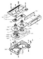
- FIG. 1 is an exploded perspective view showing an example of the configuration of the cartridge according to the embodiment of the present disclosure.
- 2A and 2B are schematic views for explaining a method of measuring the coefficient of dynamic friction between the cleaning tape and the magnetic head, respectively.
- FIG. 3 is an exploded perspective view showing an example of the configuration of the cartridge according to the modified example of the embodiment of the present disclosure.
- FIG. 1 is an exploded perspective view showing an example of the configuration of a cleaning cartridge (hereinafter, simply referred to as “cartridge”) 10 according to an embodiment of the present disclosure.
- the cartridge 10 is used as a recording / reproducing device for a linear recording format.
- the cartridge 10 conforms to the LTO (Linear Tape-Open) standard.
- the cartridge 10 is a 1-reel type.
- the cartridge 10 includes a reel 13 on which a cleaning tape CT is wound inside a cartridge case 12 composed of a lower shell 12A and an upper shell 12B, and a reel lock 14 and a reel spring 15 for locking the rotation of the reel 13.
- the spider 16 for releasing the locked state of the reel 13, the slide door 17 for opening and closing the tape outlet 12C provided in the cartridge case 12 straddling the lower shell 12A and the upper shell 12B, and the slide door 17 being taped.
- a door spring 18 for urging the closing position of the outlet 12C and a cartridge memory 11 are provided.
- the reel 13 has a substantially disk shape having an opening in the center, and is composed of a reel hub 13A and a flange 13B made of a hard material such as plastic.
- a leader pin 19 is provided at one end of the cleaning tape CT on the winding end side.
- a leader tape may be provided at one end on the winding end side of the cleaning tape CT.
- one end of the leader tape and one end of the cleaning tape CT may be connected via the splice tape, and a leader pin may be provided at the other end of the leader tape.
- the adhesiveness between the cleaning tape CT and the splice tape is low, it is preferable to provide the leader pin 19 directly at one end of the cleaning tape CT.
- the cartridge 10 is configured to be loadable with respect to the recording / playback device.
- the cartridge memory 11 is provided in the vicinity of one corner of the cartridge 10. When the cartridge 10 is loaded in the recording / playback device, the cartridge memory 11 faces the reader / writer of the recording / playback device.
- the cartridge memory 11 communicates with a recording / playback device, specifically, a reader / writer of the recording / playback device, for example, in a wireless communication standard compliant with the LTO standard.
- the cartridge memory 11 stores information and the like that can confirm that the tape wound around the cartridge 10 is a cleaning tape CT.
- the cleaning tape CT cleans the magnetic head by sliding on the magnetic head provided in the recording / playback device.
- the width of the cleaning tape CT may be 1/2 inch or wider than 1/2 inch.
- the width of the cleaning tape CT is 1/2 inch.
- the cleaning tape CT is made of a tape-shaped non-woven fabric. In the cartridge 10 in which the cleaning tape CT is made of a tape-shaped non-woven fabric, the cleaning effect can be improved as compared with a conventional cartridge (for example, UCC) in which the cleaning tape is made of a magnetic tape.
- the non-woven fabric is composed of, for example, synthetic fibers.
- Synthetic fibers include, for example, at least one selected from the group consisting of polyester fibers, cellulose fibers, nylon fibers, vinylon fibers, polyethylene fibers, polypropylene fibers, polyolefin fibers, aramid fibers and rayon fibers.
- the polyester fiber includes, for example, at least one selected from the group consisting of polyethylene terephthalate (PET) fiber, polyethylene naphthalate (PEN) fiber, polytrimethylene terephthalate (PTT fiber) and polybutylene terephthalate (PBT) fiber.
- the non-woven fabric conforms to the provisions of JIS L 0222. That is, in the present disclosure, a non-woven fabric is a fiber sheet, a web, or the like in which fibers are oriented in one direction or randomly, and the fibers are bonded by entanglement, / or fusion, and / or adhesion. is there. However, paper, woven fabrics, knitted fabrics, tufts and fluffs are excluded.
- the fibers constituting the non-woven fabric are preferably oriented in the longitudinal direction of the cleaning tape CT. By orienting the fibers in the longitudinal direction in this way, it is possible to suppress dust generation from both end faces in the width direction of the cleaning tape CT. It is preferable that the non-woven fabric does not contain a binder. Since the non-woven fabric does not contain a binder, it is possible to prevent the binder from adhering to the surface of the magnetic head when the magnetic head is slid on the cleaning tape CT.
- the magnetic head means a recording head and a reproducing head.
- the cleaning tape CT is unwound from the cartridge 10 and cut to obtain a measurement sample having a length of 100 mm and a width of the cleaning tape CT (for example, 1/2 inch).
- a binder is extracted from the measurement sample using methyl ethyl ketone as a solvent, and analysis is performed using liquid chromatography to confirm whether or not the non-woven fabric contains a binder.
- the upper limit of the basis weight of the non-woven fabric is preferably 25 g / m 2 or less.
- the basis weight of the non-woven fabric is 25 g / m 2 or less, the non-woven fabric can contain a sufficient amount of voids, so that the cleaning effect can be improved. Further, when the non-woven fabric contains a sufficient amount of voids, it is possible to prevent the non-woven fabric from becoming hard. Therefore, damage to the magnetic head due to cleaning can be suppressed.
- the lower limit of the basis weight of the non-woven fabric is preferably 10 g / m 2 or more.
- the basis weight of the non-woven fabric is 10 g / m 2 or more, the decrease in the amount of fibers constituting the non-woven fabric can be suppressed, so that the decrease in the tensile strength of the non-woven fabric can be suppressed.
- the upper limit of the average fiber diameter of the non-woven fabric is preferably 11 ⁇ m or less.
- the non-woven fabric can contain a sufficient amount of voids, so that the cleaning effect can be improved. Further, when the non-woven fabric contains a sufficient amount of voids, it is possible to prevent the non-woven fabric from becoming hard. Therefore, damage to the magnetic head due to cleaning can be suppressed.
- the lower limit of the average fiber diameter of the non-woven fabric is preferably 9 ⁇ m or more.
- the average fiber diameter of the non-woven fabric is 9 ⁇ m or more, it is possible to prevent the fibers constituting the non-woven fabric from becoming too thin, so that it is possible to suppress a decrease in the tensile strength of the non-woven fabric.
- the average fiber diameter of the non-woven fabric is obtained as follows. First, a measurement sample is prepared by unwinding and cutting the cleaning tape CT to be measured. Next, the surface of the measurement sample is observed with a scanning electron microscope (SEM) under the following conditions to obtain an SEM image. Equipment: Hitachi High-Technologies Corporation, S-4800 Acceleration voltage: 5kV Magnification: 2500 times
- the fiber diameter of each of the 50 selected fibers is measured.
- the measurement position of the fiber diameter is randomly selected from the above-mentioned parallel points among the selected fibers.
- the measured fiber diameters are simply averaged (arithmetic mean) to obtain the average fiber diameter.
- the upper limit of the average thickness of the non-woven fabric is preferably 100 ⁇ m or less, more preferably 70 ⁇ m or less. When the thickness of the non-woven fabric is 100 ⁇ m or less, the contact between the cleaning tape CT and the head block is properly maintained, and a stable cleaning effect can be exhibited.
- the lower limit of the average thickness of the non-woven fabric is preferably 40 ⁇ m or more.
- the average thickness of the non-woven fabric is 40 ⁇ m or more, it is possible to suppress a decrease in the tensile strength of the non-woven fabric.
- the average thickness of the non-woven fabric is calculated as follows. First, the cleaning tape CT is unwound from the cartridge 10, and the thickness of the non-woven fabric is measured at five or more points in the longitudinal direction. Next, the average thickness of the non-woven fabric is calculated by simply averaging the measured values (arithmetic mean). The thickness is measured in accordance with the method A described in JIS L 1913: 2010. The measurement position is randomly selected from the position in the longitudinal direction of the cleaning tape CT.
- the coefficient of dynamic friction ⁇ of the non-woven fabric is preferably 0.04 or less, more preferably 0.03 or less.
- the coefficient of dynamic friction ⁇ of the non-woven fabric means the coefficient of dynamic friction on the cleaning surface on which the magnetic head is slid.
- the dynamic friction coefficient ⁇ is obtained as follows. First, the cleaning tape CT is unwound from the cartridge 10 and cut out to a length of 30 cm. Next, as shown in FIG. 2A, the cut cleaning tape CT is placed on two 1-inch diameter columnar guide rolls 73A and 73B arranged in parallel with each other so that the cleaning surface is in contact with each other. .. The two guide rolls 73A and 73B are fixed to a hard plate-shaped member 76, whereby the positional relationship between the two guide rolls 73A and 73B is fixed to each other.
- the head block 74 is arranged substantially at the center of the guide rolls 73A and 73B.
- the head block 74 is movably attached to the plate-shaped member 76 so that the holding angle ⁇ 1 can be changed, but when the holding angle ⁇ 1 (°) becomes 5.6 °, the position is plate-shaped. It is fixed to the member 76, whereby the positional relationship between the guide rolls 73A and 73B and the head block 74 is also fixed.
- One end of the cleaning tape CT is connected to the movable strain gauge 71 via a jig 72.
- the cleaning tape CT is fixed to the jig 72 as shown in FIG. 2B.
- a weight 75 is connected to the other end of the cleaning tape CT.
- the weight 75 applies a tension of 0.6 N (T 0 [N]) in the longitudinal direction of the cleaning tape CT.
- the movable strain gauge 71 is fixed on the base 77.
- the positional relationship between the base 77 and the plate-shaped member 76 is also fixed, whereby the positional relationship between the guide rolls 73A and 73B, the head block 74, and the movable strain gauge 71 is fixed.
- the movable strain gauge 71 slides the cleaning tape CT 60 mm onto the head block 74 (outward) and away from the movable strain gauge 71 so that the cleaning tape CT is directed toward the movable strain gauge 71 at 10 mm / s. Slide 60 mm so as to (return route).
- the output value (voltage) of the movable strain gauge 71 at the time of sliding is converted into a load T [N] based on the linear relationship (described later) between the output value and the load acquired in advance.
- T [N] is acquired 13 times, and 11 T [N] excluding the first and last two times are simply averaged.
- the coefficient of dynamic friction ⁇ is calculated from the following equation.
- the above linear relationship can be obtained as follows. That is, the output value (voltage) of the movable strain gauge 71 is obtained for each of the case where a load of 0.5 N is applied to the movable strain gauge 71 and the case where a load of 1.0 N is applied. From the two output values obtained and the above two loads, a linear relationship between the output value and the load can be obtained. Using this linear relationship, the output value (voltage) of the movable strain gauge 71 during sliding is converted to T [N] as described above.
- the height of the load area ratio of the non-woven fabric of 0% is preferably ⁇ 10 ⁇ m or more.
- the fibers constituting the non-woven fabric are densely gathered, so that it is possible to prevent the collected deposits from falling off again.
- the height of the load area ratio of the non-woven fabric of 50% is preferably within ⁇ 2 ⁇ m.
- the contact with the magnetic head can be made close.
- the height of the load area ratio of the non-woven fabric of 100% is preferably 10 ⁇ m or less. When the height of the load area ratio of the non-woven fabric of 100% is 10 ⁇ m or less, the contact with the magnetic head can be maintained.
- the heights of 0%, 50%, and 100% of the load area ratio of the non-woven fabric are obtained as follows.
- the load curve is obtained by an analyzer from the shape measured at an objective lens magnification of 20 times using a non-contact optical roughness measuring machine VertScan, and the heights at load area ratios of 0%, 50%, and 100% are obtained, respectively.
- the lower limit of the tensile strength of the non-woven fabric is preferably 15 N / 50 mm or more, more preferably 19 N / 50 mm or more. When the strength of the non-woven fabric is 15 N / 50 mm, it can sufficiently withstand the tension applied when cleaning the magnetic head.
- the upper limit of the tensile strength of the non-woven fabric is preferably 30 N / 50 mm or less from the viewpoint of suppressing an increase in the thickness of the non-woven fabric.
- the tensile strength of the non-woven fabric is obtained as follows. First, by unwinding and cutting the cleaning tape CT from the cartridge 10, 10 measurement samples having a length of 70 mm and a width of the cleaning tape CT (for example, 1/2 inch) are prepared. These measurement samples are taken out every 10 m in the longitudinal direction. Next, with a tensile strength tester (manufactured by Shimadzu Corporation, AG-IS100N), both ends of the measurement sample in the longitudinal direction are set so that the measurement length (the length of the ungrasped portion of the measurement sample) is 50 mm. After grasping, the maximum load value (N) until the measurement sample breaks when the measurement sample is pulled in the longitudinal direction at a speed of 300 mm / min is measured. This measurement is performed on 10 measurement samples, and the measured maximum load value (N) is simply averaged (arithmetic mean) to calculate the average value, and this average value is used as the tensile strength of the non-woven fabric.
- a tensile strength tester manufactured by Shimadzu
- the average fiber diameter of the tape-shaped non-woven fabric constituting the cleaning tape CT is 11 ⁇ m or less, a good cleaning effect can be obtained while suppressing damage to the magnetic head due to cleaning.
- FIG. 3 is an exploded perspective view showing an example of the configuration of the 2-reel type cartridge 121.
- the cartridge 121 is a synthetic resin upper half 102, a transparent window member 123 that is fitted and fixed to a window portion 102a opened on the upper surface of the upper half 102, and a reel 106 that is fixed to the inside of the upper half 102. , 107
- the reel holder 122 that prevents the lift of the 107, the lower half 105 that corresponds to the upper half 102, the reels 106, 107, and the reels 106, 107 that are stored in the space formed by combining the upper half 102 and the lower half 105.
- the wound cleaning tape CT1, the front lid 109 that closes the front opening formed by combining the upper half 102 and the lower half 105, and the back lid 110 that protects the cleaning tape CT1 exposed on the front opening. Be prepared.
- the reel 106 has a lower flange 106b having a cylindrical hub portion 106a around which the cleaning tape CT1 is wound in the center, an upper flange 106c having substantially the same size as the lower flange 106b, and between the hub portion 106a and the upper flange 106c. It is provided with a sandwiched reel plate 111.
- the reel 107 has the same configuration as the reel 106.
- the window member 123 is provided with mounting holes 123a for assembling the reel holder 122, which is a reel holding means for preventing the reels 106 and 107 from floating, at positions corresponding to the reels 106 and 107.
- the cleaning tape CT1 is the same as the cleaning tape CT in the first embodiment.
- the 2-reel type cartridge 121 is provided with the cleaning tape CT1
- the 2-reel type magnetic tape cartridge may be provided with the cleaning tape CT1.
- the cleaning tape CT1 may be provided on at least one of the winding end side end side and the winding start side end side of the magnetic tape.
- Examples 1 and 2 Comparative Example 1
- a cleaning tape a non-woven fabric having the specifications shown in Table 1 was prepared.
- a cleaning tape was produced by cutting the non-woven fabric into a tape having a width of 1/2 inch.
- a cartridge case conforming to the LTO standard having the configuration shown in FIG. 1 is prepared, one end of the cleaning tape is attached to the reel of the cartridge case, the cleaning tape is wound up to a length of 30 m, and then the winding end.
- a leader pin was attached to the other end on the side. As a result, the desired cartridge was obtained.
- Example 2 As the cleaning tape, a cartridge was obtained in the same manner as in Example 1 except that a tape-shaped woven cloth in which PET fibers were woven in a lattice pattern having the specifications shown in Table 1 was used.
- Example 3 A cartridge was obtained in the same manner as in Example 1 except that a tape-shaped knit (knit) in which PET fibers were knitted, which had the specifications shown in Table 1, was used as the cleaning tape.
- Example 4 As the cleaning tape, a magnetic tape having the specifications shown in Table 1 was used, and a cartridge (that is, a conventional UCC) was obtained in the same manner as in Example 1 except that the magnetic tape having the specifications shown in Table 1 was wound around the cartridge for 319 m.
- the generation of dust on the end face of the cleaning tape was evaluated as follows. First, after loading the cartridge into the drive, the cleaning tape was reciprocated 10 times to perform the cleaning process. Next, the edge (cutting surface) of the cleaning tape was observed with an optical microscope in a range of 30 mm in length, and the presence or absence of end face dust was confirmed.
- the number of times the cleaning tape was used was evaluated as follows. First, the magnetic tape cartridge was loaded into the drive, the magnetic tape was run, powder was dropped from the magnetic tape onto the magnetic head, deposits were adhered to the head, and then the magnetic tape cartridge was unloaded from the drive. Next, the cleaning tape cartridge was loaded into the drive, the cleaning tape was reciprocated once to perform a cleaning process on the magnetic head, and then the cleaning tape cartridge was unloaded from the drive. Next, the magnetic head was observed with an optical microscope to confirm whether or not the deposits were removed.
- the cleaning effect of the cartridge was evaluated as follows. First, data was recorded on the entire surface of the magnetic tape of the LTO8 standard cartridge by the LTO8 standard drive. Next, the recording head after recording the data was observed with an optical microscope, and it was confirmed that the recording head had deposits. Next, the cleaning cartridge was loaded into the above drive, the head unit was cleaned with a cleaning tape, and the recording head was cleaned. Next, the recording head after cleaning was observed with an optical microscope. Next, the cleaning effect was evaluated according to the following criteria. Good cleaning effect: no deposits are observed Poor cleaning effect: deposits are observed
- Head damage The damage to the magnetic head when the cartridge was used was evaluated as follows. First, an LTO8 standard drive whose reproduction output before running was confirmed in advance was prepared, the cleaning tape was run 10 times, and the reproduction output was confirmed again. Next, the presence or absence of head damage was evaluated according to the following criteria. No head damage: No deterioration of 3 dB or more is observed in the playback output after running 10 times. With head damage: Deterioration of 3 dB or more is observed in the playback output after running 10 times.
- Table 1 shows the specifications and evaluation results of the cleaning tape.
- "unmeasurable” means that the measured sample did not break within the range of the measured load of the tensile strength test.
- winding length means the length of the cleaning tape wound around the cartridge.
- the upper limit value or the lower limit value of the numerical range of one step may be replaced with the upper limit value or the lower limit value of the numerical range of another step.
- the present disclosure may also adopt the following configuration.
- Tape-shaped non-woven fabric and The reel on which the non-woven fabric is wound and A case for accommodating the reel is provided.
- the cartridge according to (1) or (2), wherein the average fiber diameter of the non-woven fabric is 9 ⁇ m or more and 11 ⁇ m or less.
- the cartridge according to any one of (1) to (4), wherein the average thickness of the non-woven fabric is 100 ⁇ m or less.
- the height of the load area ratio of the non-woven fabric of 0% is ⁇ 10 ⁇ m or more.
- the height of the load area ratio of the non-woven fabric of 50% is within ⁇ 2 ⁇ m.
Landscapes
- Engineering & Computer Science (AREA)
- Textile Engineering (AREA)
- Chemical & Material Sciences (AREA)
- Chemical Kinetics & Catalysis (AREA)
- Manufacturing Of Magnetic Record Carriers (AREA)
- Magnetic Record Carriers (AREA)
Abstract
カートリッジは、テープ状の不織布と、不織布が巻かれたリールと、リールを収容するケースとを備える。不織布の目付量が、25g/m2以下である。
Description
本開示は、クリーニングテープおよびカートリッジに関する。
電子データの保存のため、磁気テープカートリッジ(例えばLTO Ultrium規格のカートリッジ)が幅広く利用されている。磁気テープカートリッジ用のドライブでは、磁気ヘッドをクリーニングするために、クリーニングカートリッジが使用される。リニア記録フォーマット用のクリーニングカートリッジ(例えばUniversal Cleaning Cartridge:UCC)では、クリーニングテープとして磁気テープが用いられている(例えば特許文献1参照)。
しかしながら、クリーニングテープとして磁気テープを用いたクリーニングカートリッジでは、磁気ヘッドのクリーニング効果が低いという問題がある。
近年では、磁気テープを高記録密度化(例えば高トラック密度化)するために、ドライブの磁気ヘッドとしてGMR(Giant MagnetoResistive)ヘッドやTMR(Tunnel Magnetoresistive)ヘッド等の高性能な磁気ヘッドが用いられている。このような高性能な磁気ヘッドに数nm程度の付着物が付着すると、ドライブの記録再生性能に大きな影響が及ぼされる。このため、高性能な磁気ヘッドを備えたドライブでは、クリーニングカートリッジのクリーニング効果の低さは特に問題となる。
本開示の目的は、良好なクリーニング効果を有するクリーニングテープおよびカートリッジを提供することにある。
上述の課題を解決するために、第1の開示は、
テープ状の不織布と、
不織布が巻かれたリールと、
リールを収容するケースと
を備え、
不織布の目付量が、25g/m2以下であるカートリッジである。
テープ状の不織布と、
不織布が巻かれたリールと、
リールを収容するケースと
を備え、
不織布の目付量が、25g/m2以下であるカートリッジである。
第2の開示は、
テープ状の不織布と、
不織布が巻かれたリールと、
リールを収容するケースと
を備え、
不織布の平均繊維径が、11μm以下であるカートリッジである。
テープ状の不織布と、
不織布が巻かれたリールと、
リールを収容するケースと
を備え、
不織布の平均繊維径が、11μm以下であるカートリッジである。
第3の開示は、
テープ状の不織布を含み、
不織布の目付量が、25g/m2以下であるクリーニングテープである。
テープ状の不織布を含み、
不織布の目付量が、25g/m2以下であるクリーニングテープである。
第4の開示は、
テープ状の不織布を含み、
不織布の平均繊維径が、11μm以下であるクリーニングテープである。
テープ状の不織布を含み、
不織布の平均繊維径が、11μm以下であるクリーニングテープである。
本開示の実施形態について、以下の順序で説明する。
1 クリーニングカートリッジの構成
2 クリーニングテープの構成
3 効果
4 変形例
1 クリーニングカートリッジの構成
2 クリーニングテープの構成
3 効果
4 変形例
[1 クリーニングカートリッジの構成]
図1は、本開示の一実施形態に係るクリーニングカートリッジ(以下単に「カートリッジ」という。)10の構成の一例を示す分解斜視図である。カートリッジ10は、リニア記録フォーマット用の記録再生装置に用いられる。具体的には例えば、カートリッジ10は、LTO(Linear Tape-Open)規格に準拠している。カートリッジ10は、1リールタイプである。
図1は、本開示の一実施形態に係るクリーニングカートリッジ(以下単に「カートリッジ」という。)10の構成の一例を示す分解斜視図である。カートリッジ10は、リニア記録フォーマット用の記録再生装置に用いられる。具体的には例えば、カートリッジ10は、LTO(Linear Tape-Open)規格に準拠している。カートリッジ10は、1リールタイプである。
カートリッジ10は、下シェル12Aと上シェル12Bとで構成されるカートリッジケース12の内部に、クリーニングテープCTが巻かれたリール13と、リール13の回転をロックするためのリールロック14およびリールスプリング15と、リール13のロック状態を解除するためのスパイダ16と、下シェル12Aと上シェル12Bに跨ってカートリッジケース12に設けられたテープ引出口12Cを開閉するスライドドア17と、スライドドア17をテープ引出口12Cの閉位置に付勢するドアスプリング18と、カートリッジメモリ11とを備える。リール13は、中心部に開口を有する略円盤状であって、プラスチック等の硬質の材料からなるリールハブ13Aとフランジ13Bとにより構成される。クリーニングテープCTの巻き終わり側の一端には、リーダーピン19が設けられている。
クリーニングテープCTの巻き終わり側の一端にリーダーテープが設けられていてもよい。この場合、スプライステープを介してリーダーテープの一端とクリーニングテープCTの一端が接続され、リーダーテープの他端にリーダーピンが設けられていてもよい。但し、クリーニングテープCTとスプライステープの接着性が低いたので、クリーニングテープCTの一端に直接リーダーピン19を設けることが好ましい。
カートリッジ10は、記録再生装置に対してロード可能に構成されている。カートリッジメモリ11は、カートリッジ10の1つの角部の近傍に設けられている。カートリッジ10が記録再生装置にロードされた状態において、カートリッジメモリ11は、記録再生装置のリーダライタと対向するようになっている。カートリッジメモリ11は、例えば、LTO規格に準拠した無線通信規格で記録再生装置、具体的には記録再生装置のリーダライタと通信を行う。カートリッジメモリ11には、カートリッジ10に巻かれているテープがクリーニングテープCTであることを確認できる情報等が記憶されている。
[2 クリーニングテープの構成]
クリーニングテープCTは、記録再生装置に備えられた磁気ヘッドに摺動されることで、磁気ヘッドをクリーニングする。クリーニングテープCTの幅は、1/2インチであってもよいし、1/2インチよりも広くてもよい。カートリッジ10がLTO規格に準拠するものである場合には、クリーニングテープCTの幅は、1/2インチである。クリーニングテープCTは、テープ状の不織布により構成されている。クリーニングテープCTがテープ状の不織布により構成されているカートリッジ10では、クリーニングテープが磁気テープにより構成されている従来のカートリッジ(例えばUCC)に比べてクリーニング効果を向上することができる。
クリーニングテープCTは、記録再生装置に備えられた磁気ヘッドに摺動されることで、磁気ヘッドをクリーニングする。クリーニングテープCTの幅は、1/2インチであってもよいし、1/2インチよりも広くてもよい。カートリッジ10がLTO規格に準拠するものである場合には、クリーニングテープCTの幅は、1/2インチである。クリーニングテープCTは、テープ状の不織布により構成されている。クリーニングテープCTがテープ状の不織布により構成されているカートリッジ10では、クリーニングテープが磁気テープにより構成されている従来のカートリッジ(例えばUCC)に比べてクリーニング効果を向上することができる。
不織布は、例えば、合成繊維により構成されている。合成繊維は、例えば、ポリエステル繊維、セルロース繊維、ナイロン繊維、ビニロン繊維、ポリエチレン繊維、ポリプロピレン繊維、ポリオレフィン繊維、アラミド繊維およびレーヨン繊維からなる群より選ばれる少なくとも1種を含む。ポリエステル繊維は、例えば、ポリエチレンテレフタレート(PET)繊維、ポリエチレンナフタレート(PEN)繊維、ポリトリメチレンテレフタレート(PTT繊維)およびポリブチレンテレフタレート(PBT)繊維からなる群より選ばれる少なくとも1種を含む。
本開示において、不織布とは、JIS L 0222の規定に準拠するものである。すなわち、本開示において、不織布とは、繊維シートまたはウェブ等で、繊維が一方向またはランダムに配向しており、交絡、および/または融着、および/または接着によって繊維間が結合されたものである。但し、紙、織物、編物、タフトおよび縮絨を除く。
不織布を構成する繊維は、クリーニングテープCTの長手方向に配向していることが好ましい。このように繊維が長手方向に配向していることで、クリーニングテープCTの幅方向の両端面からの発塵を抑制することができる。不織布が、バインダを含まないことが好ましい。不織布がバインダを含まないことで、磁気ヘッドをクリーニングテープCTに摺動させた際に、磁気ヘッドの表面にバインダが付着することを抑制することができる。本明細書において、磁気ヘッドとは、記録ヘッドおよび再生ヘッドを意味する。
不織布が、バインダを含むか否かは以下のようにして確認される。まず、カートリッジ10からクリーニングテープCTを巻き出し、切断することにより、長さ100mm×クリーニングテープCTの幅(例えば1/2インチ)の測定サンプルを得る。次に、溶剤としてメチルエチルケトンを用いて測定サンプルからバインダの抽出を行い、液体クロマトグラフィーを用いて解析することにより、不織布がバインダを含むか否かが確認される。
(不織布の目付量)
不織布の目付量の上限値が、25g/m2以下であることが好ましい。不織布の目付量が25g/m2以下であると、不織布が十分な量の空隙を含むことができるので、クリーニング効果を向上することができる。また、不織布が十分な量の空隙を含むことで、不織布が固くなることを抑制することができる。したがって、クリーニングによる磁気ヘッドのダメージを抑制することができる。
不織布の目付量の上限値が、25g/m2以下であることが好ましい。不織布の目付量が25g/m2以下であると、不織布が十分な量の空隙を含むことができるので、クリーニング効果を向上することができる。また、不織布が十分な量の空隙を含むことで、不織布が固くなることを抑制することができる。したがって、クリーニングによる磁気ヘッドのダメージを抑制することができる。
不織布の目付量の下限値は、10g/m2以上であることが好ましい。不織布の目付量が10g/m2以上であると、不織布を構成する繊維量の減少を抑制することができるので、不織布の引張強度の低下を抑制することができる。
不織布の目付量は以下のようにして求められる。まず、カートリッジ10からクリーニングテープCTを巻き出し、切断することにより、長さ100mm×クリーニングテープCTの幅(例えば1/2インチ)の測定サンプルを得る。次に、測定サンプルの質量Mを測定したのち、下記の式から不織布の目付量を求める。
不織布の目付量[mg/cm2]=(測定サンプルの質量M)/(測定サンプルの面積S)
不織布の目付量[mg/cm2]=(測定サンプルの質量M)/(測定サンプルの面積S)
(不織布の平均繊維径)
不織布の平均繊維径の上限値が、11μm以下であることが好ましい。不織布の平均繊維径が11μm以下であると、不織布が十分な量の空隙を含むことができるので、クリーニング効果を向上することができる。また、不織布が十分な量の空隙を含むことで、不織布が固くなることを抑制することができる。したがって、クリーニングによる磁気ヘッドのダメージを抑制することができる。
不織布の平均繊維径の上限値が、11μm以下であることが好ましい。不織布の平均繊維径が11μm以下であると、不織布が十分な量の空隙を含むことができるので、クリーニング効果を向上することができる。また、不織布が十分な量の空隙を含むことで、不織布が固くなることを抑制することができる。したがって、クリーニングによる磁気ヘッドのダメージを抑制することができる。
不織布の平均繊維径の下限値が、9μm以上であることが好ましい。不織布の平均繊維径が9μm以上であると、不織布を構成する繊維が細くなりすぎることを抑制することができるので、不織布の引張強度の低下を抑制することができる。
不織布の平均繊維径は以下のようにして求められる。まず、測定対象となるクリーニングテープCTを巻き出し、切断することにより測定サンプルを作製する。次に、測定サンプルの表面を走査型電子顕微鏡(Scanning Electron Microscope:SEM)により、下記の条件で観察しSEM像を得る。
装置:株式会社日立ハイテクノロジーズ製、S-4800
加速電圧:5kV
倍率:2500倍
装置:株式会社日立ハイテクノロジーズ製、S-4800
加速電圧:5kV
倍率:2500倍
次に、得られたSEM像から、観察面とほぼ平行になっている平行箇所を有し、且つ、繊維径を明らかに確認できる繊維を50個選び出す。そして、選び出された50個の繊維それぞれの繊維径を測定する。繊維径の測定位置は、選び出された繊維のうちの上記平行箇所から無作為に選ばれる。次に、測定した繊維径を単純に平均(算術平均)して平均繊維径を求める。
(不織布の平均厚み)
不織布の平均厚みの上限値は、好ましくは100μm以下、より好ましくは70μm以下である。不織布の厚みが100μm以下であると、クリーニングテープCTとヘッドブロックの接触が適切に保たれ、安定したクリーニング効果を発揮することができる。
不織布の平均厚みの上限値は、好ましくは100μm以下、より好ましくは70μm以下である。不織布の厚みが100μm以下であると、クリーニングテープCTとヘッドブロックの接触が適切に保たれ、安定したクリーニング効果を発揮することができる。
不織布の平均厚みの下限値は、好ましくは40μm以上である。不織布の平均厚みが40μm以上であると、不織布の引張強度の低下を抑制することができる。
不織布の平均厚みは、以下のようにして求められる。まず、カートリッジ10からクリーニングテープCTを巻き出し、長手方向に5点以上の位置で不織布の厚みを測定する。次に、測定値を単純に平均(算術平均)して、不織布の平均厚みを算出する。厚みの測定は、JIS L 1913:2010に記載のA法に準拠して行われる。測定位置は、クリーニングテープCTの長手方向の位置から無作為に選ばれる。
(不織布の動摩擦係数μ)
不織布の動摩擦係数μは、好ましくは0.04以下、より好ましくは0.03以下である。不織布の動摩擦係数μが0.04以下であると、クリーンングによる磁気ヘッドのダメージを抑制することができる。ここで、不織布の動摩擦係数μは、磁気ヘッドが摺動されるクリーニング面における動摩擦係数を意味する。
不織布の動摩擦係数μは、好ましくは0.04以下、より好ましくは0.03以下である。不織布の動摩擦係数μが0.04以下であると、クリーンングによる磁気ヘッドのダメージを抑制することができる。ここで、不織布の動摩擦係数μは、磁気ヘッドが摺動されるクリーニング面における動摩擦係数を意味する。
動摩擦係数μは以下のようにして求められる。まず、カートリッジ10から、クリーニングテープCTを巻き出し、長さ30cm切り取る。次に、図2Aに示すように、切り取ったクリーニングテープCTを、互いに離間して平行に配置された1インチ径の円柱状の2本のガイドロール73Aおよび73Bにクリーニング面が接触するように載せる。2本のガイドロール73Aおよび73Bは、硬い板状部材76に固定されており、これにより互いの位置関係が固定されている。
次いで、LTO5ドライブに搭載されているヘッドブロック(記録再生用)74に対し、クリーニングテープCTを、クリーニング面が接触するように且つ抱き角θ1(°)=5.6°となるように接触させる。ヘッドブロック74は、ガイドロール73Aおよび73Bの略中心に配置される。ヘッドブロック74は、抱き角θ1を変更することができるように、板状部材76に移動可能に取り付けられているが、抱き角θ1(°)が5.6°となったらその位置が板状部材76に対して固定され、これにより、ガイドロール73Aおよび73Bとヘッドブロック74との位置関係も固定される。
クリーニングテープCTの一端を、ジグ72を介して可動式ストレインゲージ71と繋ぐ。クリーニングテープCTは、図2Bに示される通りにジグ72に固定される。クリーニングテープCTの他端に錘75を繋ぐ。錘75によって、0.6Nのテンション(T0[N])がクリーニングテープCTの長手方向に付与される。可動式ストレインゲージ71は、台77上に固定されている。台77と板状部材76の位置関係も固定されており、これにより、ガイドロール73Aおよび73B、ヘッドブロック74、および可動式ストレインゲージ71の位置関係が固定されている。
可動式ストレインゲージ71によって、クリーニングテープCTが10mm/sにて可動式ストレインゲージ71へ向かうように、クリーニングテープCTをヘッドブロック74上に60mm摺動させ(往路)および可動式ストレインゲージ71から離れるように60mm摺動させる(復路)。当該摺動時の可動式ストレインゲージ71の出力値(電圧)を、事前に取得されている出力値と荷重との直線関係(後述する)に基づき、荷重T[N]に変換する。上記60mmの摺動の摺動開始から摺動停止までの間に、13回T[N]を取得し、最初と最後の計2回を除いた11個のT[N]を単純平均することによって、Tave[N]が得られる。その後、以下の式より動摩擦係数μを求める。

上記直線関係は以下の通りに得られる。すなわち、可動式ストレインゲージ71に0.5Nの荷重をかけた場合と1.0Nの荷重をかけた場合のそれぞれについて、可動式ストレインゲージ71の出力値(電圧)を得る。得られた2つの出力値と上記2つの荷重とから、出力値と荷重との直線関係が得られる。当該直線関係を用いて、上記の通り、摺動時の可動式ストレインゲージ71による出力値(電圧)がT[N]に変換される。
(不織布の負荷面積率0%、50%、100%の高さ)
不織布の負荷面積率0%の高さが、-10μm以上であることが好ましい。不織布の負荷面積率0%の高さが-10μm以上であると、不織布を構成する繊維が緻密に集まっているため、捕集した付着物を再脱落しにくくすることができる。
不織布の負荷面積率0%の高さが、-10μm以上であることが好ましい。不織布の負荷面積率0%の高さが-10μm以上であると、不織布を構成する繊維が緻密に集まっているため、捕集した付着物を再脱落しにくくすることができる。
不織布の負荷面積率50%の高さが、±2μm以内であることが好ましい。不織布の負荷面積率50%の高さが±2μm以内であると、磁気ヘッドとの接触を密にすることができる。
不織布の負荷面積率100%の高さが、10μm以下であることが好ましい。不織布の負荷面積率100%の高さが10μm以下であると、磁気ヘッドとの接触を維持することができる。
不織布の負荷面積率0%、50%、100%の高さは以下のようにして求められる。非接触式光学粗度測定機VertScanを用いて対物レンズ倍率20倍で測定した形状から解析装置により負荷曲線を求め、負荷面積率0%、50%、100%の時の高さをそれぞれ求める。
(不織布の引張強度)
不織布の引張強度の下限値は、好ましくは15N/50mm以上、より好ましくは19N/50mm以上である。不織布の強度が15N/50mmであると、磁気ヘッドのクリーニング時に加わる張力に十分耐えることができる。
不織布の引張強度の下限値は、好ましくは15N/50mm以上、より好ましくは19N/50mm以上である。不織布の強度が15N/50mmであると、磁気ヘッドのクリーニング時に加わる張力に十分耐えることができる。
不織布の引張強度の上限値は、不織布の厚みの増加を抑制する観点からすると、30N/50mm以下であることが好ましい。
不織布の引張強度は以下のようにして求められる。まず、カートリッジ10からクリーニングテープCTを巻き出し切断することにより、長さ70mm×クリーニングテープCTの幅(例えば1/2インチ)の測定サンプルを10個準備する。これらの測定サンプルは、長手方向に10mおきに取り出される。次に、引張強度試験機(株式会社島津製作所社製、AG-IS 100N)により、測定長(測定サンプルの未把持部分の長さ)が50mmとなるように、測定サンプルの長手方向の両端を把持したのち、測定サンプルを長手方向に速度300mm/分で引っ張ったときの、測定サンプルが破断するまでの最大荷重値(N)を測定する。この測定を10個の測定サンプルに対して行い、測定した最大荷重値(N)を単純に平均(算術平均)して平均値を算出し、この平均値を不織布の引張強度とする。
[3 効果]
上述したように、一実施形態に係るカートリッジ10では、クリーニングテープCTを構成するテープ状の不織布の目付量が25g/m2以下であると、クリーニングによる磁気ヘッドのダメージを抑制しつつ、良好なクリーニング効果を得ることができる。
上述したように、一実施形態に係るカートリッジ10では、クリーニングテープCTを構成するテープ状の不織布の目付量が25g/m2以下であると、クリーニングによる磁気ヘッドのダメージを抑制しつつ、良好なクリーニング効果を得ることができる。
クリーニングテープCTを構成するテープ状の不織布の平均繊維径が11μm以下であると、クリーニングによる磁気ヘッドのダメージを抑制しつつ、良好なクリーニング効果を得ることができる。
[4 変形例]
(変形例1)
上述の一実施形態では、カートリッジ10がクリーニングテープCTを備える場合について説明したが、磁気テープカートリッジがクリーニングテープCTを備えるようにしてもよい。この場合、クリーニングテープCTは、磁気テープの巻き終わり側の一端および巻き始め側の一端のうちの少なくとも一方に設けられていてもよい。
(変形例1)
上述の一実施形態では、カートリッジ10がクリーニングテープCTを備える場合について説明したが、磁気テープカートリッジがクリーニングテープCTを備えるようにしてもよい。この場合、クリーニングテープCTは、磁気テープの巻き終わり側の一端および巻き始め側の一端のうちの少なくとも一方に設けられていてもよい。
(変形例2)
上述の一実施形態では、クリーニングカートリッジが、1リールタイプのカートリッジ10である場合について説明したが、2リールタイプのカートリッジであってもよい。
上述の一実施形態では、クリーニングカートリッジが、1リールタイプのカートリッジ10である場合について説明したが、2リールタイプのカートリッジであってもよい。
図3は、2リールタイプのカートリッジ121の構成の一例を示す分解斜視図である。カートリッジ121は、合成樹脂製の上ハーフ102と、上ハーフ102の上面に開口された窓部102aに嵌合されて固着される透明な窓部材123と、上ハーフ102の内側に固着されリール106、107の浮き上がりを防止するリールホルダー122と、上ハーフ102に対応する下ハーフ105と、上ハーフ102と下ハーフ105を組み合わせてできる空間に収納されるリール106、107と、リール106、107に巻かれたクリーニングテープCT1と、上ハーフ102と下ハーフ105を組み合わせてできるフロント側開口部を閉蓋するフロントリッド109およびこのフロント側開口部に露出したクリーニングテープCT1を保護するバックリッド110とを備える。
リール106は、クリーニングテープCT1が巻かれる円筒状のハブ部106aを中央部に有する下フランジ106bと、下フランジ106bとほぼ同じ大きさの上フランジ106cと、ハブ部106aと上フランジ106cの間に挟み込まれたリールプレート111とを備える。リール107はリール106と同様の構成を有している。
窓部材123には、リール106、107に対応した位置に、これらリール106、107の浮き上がりを防止するリール保持手段であるリールホルダー122を組み付けるための取付孔123aが各々設けられている。クリーニングテープCT1は、第1の実施形態におけるクリーニングテープCTと同様である。
上述の例では、2リールタイプのカートリッジ121がクリーニングテープCT1を備える場合について説明したが、2リールタイプの磁気テープカートリッジがクリーニングテープCT1を備えるようにしてもよい。この場合、クリーニングテープCT1は、磁気テープの巻き終わり側の一端および巻き始め側の一端のうちの少なくとも一方に設けられていてもよい。
以下、実施例により本開示を具体的に説明するが、本開示はこれらの実施例のみに限定されるものではない。
以下の実施例1、2、比較例1~4において、クリーニングテープの平均厚み、目付量、平均繊維径、負荷面積率0%、50%、100%の高さ、引張強度、動摩擦係数はそれぞれ、上述の一実施形態にて説明した測定方法により求められた。
[実施例1、2、比較例1]
まず、クリーニングテープとして、表1に示す仕様を有する不織布を準備した。次に、不織布を1/2インチ幅のテープ状に裁断することにより、クリーニングテープを作製した。次に、図1に示した構成を有する、LTO規格に準拠したカートリッジケースを準備し、このカートリッジケースのリールにクリーニングテープの一端を取り付け、クリーニングテープを30mの長さ巻き取ったのち、巻き終わり側となる他端にリーダーピンを取り付けた。これにより、目的とするカートリッジが得られた。
まず、クリーニングテープとして、表1に示す仕様を有する不織布を準備した。次に、不織布を1/2インチ幅のテープ状に裁断することにより、クリーニングテープを作製した。次に、図1に示した構成を有する、LTO規格に準拠したカートリッジケースを準備し、このカートリッジケースのリールにクリーニングテープの一端を取り付け、クリーニングテープを30mの長さ巻き取ったのち、巻き終わり側となる他端にリーダーピンを取り付けた。これにより、目的とするカートリッジが得られた。
[比較例2]
クリーニングテープとして、表1に示す仕様を有する、PET繊維が格子状に織られたテープ状の織布を用いたこと以外は実施例1と同様にしてカートリッジを得た。
クリーニングテープとして、表1に示す仕様を有する、PET繊維が格子状に織られたテープ状の織布を用いたこと以外は実施例1と同様にしてカートリッジを得た。
[比較例3]
クリーニングテープとして、表1に示す仕様を有する、PET繊維が編まれたテープ状のニット(編物)を用いたこと以外は実施例1と同様にしてカートリッジを得た。
クリーニングテープとして、表1に示す仕様を有する、PET繊維が編まれたテープ状のニット(編物)を用いたこと以外は実施例1と同様にしてカートリッジを得た。
[比較例4]
クリーニングテープとして、表1に示す仕様を有する磁気テープを用い、これをカートリッジに319m巻き取ったこと以外は実施例1と同様にしてカートリッジ(すなわち従来のUCC)を得た。
クリーニングテープとして、表1に示す仕様を有する磁気テープを用い、これをカートリッジに319m巻き取ったこと以外は実施例1と同様にしてカートリッジ(すなわち従来のUCC)を得た。
[評価]
上述のようにして得られたカートリッジおよびそのカートリッジに用いられたクリーニングテープについて以下の評価を行った。
上述のようにして得られたカートリッジおよびそのカートリッジに用いられたクリーニングテープについて以下の評価を行った。
(端面ダストの発生)
クリーニングテープの端面ダストの発生を以下のようにして評価した。まず、カートリッジをドライブにロードしたのち、クリーニングテープを10往復させてクリーニング処理を行った。次に、光学顕微鏡によりクリーニングテープのエッジ(裁断面)を長さ30mmの範囲観察し、端面ダストの発生の有無を確認した。
クリーニングテープの端面ダストの発生を以下のようにして評価した。まず、カートリッジをドライブにロードしたのち、クリーニングテープを10往復させてクリーニング処理を行った。次に、光学顕微鏡によりクリーニングテープのエッジ(裁断面)を長さ30mmの範囲観察し、端面ダストの発生の有無を確認した。
(使用回数)
クリーニングテープの使用回数を以下のようにして評価した。まず、磁気テープカートリッジをドライブにロードし、磁気テープを走行させて、磁気テープから磁気ヘッド上に粉落ちさせ、ヘッド上に付着物を付着させたのち、磁気テープカートリッジをドライブからアンロードした。次に、クリーニングテープカートリッジをドライブにロードし、クリーニングテープを1往復させて磁気ヘッドに対してクリーニング処理を行ったのち、クリーニングテープカートリッジをドライブからアンロードした。次に、光学顕微鏡により磁気ヘッドを観察し、付着物が除去されているか否かを確認した。
クリーニングテープの使用回数を以下のようにして評価した。まず、磁気テープカートリッジをドライブにロードし、磁気テープを走行させて、磁気テープから磁気ヘッド上に粉落ちさせ、ヘッド上に付着物を付着させたのち、磁気テープカートリッジをドライブからアンロードした。次に、クリーニングテープカートリッジをドライブにロードし、クリーニングテープを1往復させて磁気ヘッドに対してクリーニング処理を行ったのち、クリーニングテープカートリッジをドライブからアンロードした。次に、光学顕微鏡により磁気ヘッドを観察し、付着物が除去されているか否かを確認した。
上述の手順を繰り返すことにより、付着物を除去可能な、クリーニングテープカートリッジの使用回数をカウントした。
(クリーニング効果)
カートリッジのクリーニング効果を以下のようにして評価した。まず、LTO8規格のドライブにより、LTO8規格のカートリッジの磁気テープ全面にデータを記録した。次に、上記データ記録後の記録ヘッドを光学顕微鏡により観察し、記録ヘッドに付着物が付いていることを確認した。次に、上記ドライブにクリーニングカートリッジをロードし、クリーンングテープでヘッドユニットをクリーニングプロシジャでクリーニングを行い、記録ヘッドをクリーニングした。次に、クリーニング後の記録ヘッドを光学顕微鏡により観察した。次に、以下の基準によりクリーニング効果を評価した。
クリーニング効果が良好:付着物が全く観察されない
クリーニング効果が悪い:付着物が観察される
(ヘッドダメージ)
カートリッジを用いたときの磁気ヘッドのダメージを以下のようにして評価した。まず、走行前の再生出力が予め確認されたLTO8規格のドライブを準備し、クリーニングテープを10回走行させ、再度再生出力を確認した。次に、以下の基準によりヘッドダメージの有無を評価した。
ヘッドダメージの無し:10回走行後の再生出力に3dB以上の劣化が認めらない。
ヘッドダメージの有り:10回走行後の再生出力に3dB以上の劣化が認められる。
カートリッジを用いたときの磁気ヘッドのダメージを以下のようにして評価した。まず、走行前の再生出力が予め確認されたLTO8規格のドライブを準備し、クリーニングテープを10回走行させ、再度再生出力を確認した。次に、以下の基準によりヘッドダメージの有無を評価した。
ヘッドダメージの無し:10回走行後の再生出力に3dB以上の劣化が認めらない。
ヘッドダメージの有り:10回走行後の再生出力に3dB以上の劣化が認められる。
表1は、クリーニングテープの仕様および評価結果を示す。

表1中の引張強度の欄において“測定不能”とは、引張強度試験の測定荷重の範囲では測定サンプルが破断しなかったことを意味する。また、“巻長”とは、カートリッジに巻かれたクリーニングテープの長さを意味する。
表1では、比較例1~4のクリーニング効果の評価結果を一律に“悪い”と記載しているが、比較例1~4のうちでも、磁気テープをクリーニングテープとして用いている比較例4のクリーニング効果の評価結果が特に悪かった。
表1から以下のことがわかる。
クリーニングテープとして目付量が25g/m2以下であるテープ状の不織布を用いることで、ヘッドダメージを抑制しつつ、良好なクリーニング効果を得ることができる。また、端面ダストを抑制することができると共に、カートリッジの使用回数を増やすことができる。
クリーニングテープとして目付量が25g/m2以下であるテープ状の不織布を用いることで、ヘッドダメージを抑制しつつ、良好なクリーニング効果を得ることができる。また、端面ダストを抑制することができると共に、カートリッジの使用回数を増やすことができる。
クリーニングテープとして平均繊維径が11μm以下であるテープ状の不織布を用いることで、ヘッドダメージを抑制しつつ、良好なクリーニング効果を得ることができる。また、端面ダストを抑制することができると共に、カートリッジの使用回数を増やすことができる。
以上、本開示の実施形態について具体的に説明したが、本開示は、上述の実施形態に限定されるものではなく、本開示の技術的思想に基づく各種の変形が可能である。
例えば、上述の実施形態において挙げた構成、方法、工程、形状、材料および数値などはあくまでも例に過ぎず、必要に応じてこれと異なる構成、方法、工程、形状、材料および数値などを用いてもよい。
上述の実施形態の構成、方法、工程、形状、材料および数値などは、本開示の主旨を逸脱しない限り、互いに組み合わせることが可能である。
上述の実施形態で段階的に記載された数値範囲において、ある段階の数値範囲の上限値または下限値は、他の段階の数値範囲の上限値または下限値に置き換えてもよい。
上述の実施形態に例示した材料は、特に断らない限り、1種を単独でまたは2種以上を組み合わせて用いることができる。
また、本開示は以下の構成を採用することもできる。
(1)
テープ状の不織布と、
前記不織布が巻かれたリールと、
前記リールを収容するケースと
を備え、
前記不織布の目付量が、25g/m2以下であるカートリッジ。
(2)
前記不織布の平均繊維径が、11μm以下である(1)に記載のカートリッジ。
(3)
前記不織布の平均繊維径が、9μm以上11μm以下である(1)または(2)に記載のカートリッジ。
(4)
前記不織布が、バインダを含まない(1)から(3)のいずれかに記載のカートリッジ。
(5)
前記不織布の平均厚みが、100μm以下である(1)から(4)のいずれかに記載のカートリッジ。
(6)
前記不織布の動摩擦係数が、0.04以下である(1)から(5)のいずれかに記載のカートリッジ。
(7)
前記不織布の負荷面積率0%の高さが、-10μm以上であり、
前記不織布の負荷面積率50%の高さが、±2μm以内であり、
前記不織布の負荷面積率100%の高さが、10μm以下である(1)から(6)のいずれかに記載のカートリッジ。
(8)
前記不織布の引張強度が、15N/50mm以上である(1)から(7)のいずれかに記載のカートリッジ。
(9)
前記不織布が、ポリエステル繊維により構成されている(1)から(8)のいずれかに記載のカートリッジ。
(10)
前記カートリッジが、リニア記録フォーマット用の記録再生装置に用いられる(1)から(9)のいずれかに記載のカートリッジ。
(11)
前記不織布の幅が、1/2インチである(1)から(10)のいずれかに記載のカートリッジ。
(12)
前記カートリッジが、1リールタイプである(1)から(11)のいずれかに記載のカートリッジ。
(13)
前記不織布の巻き終わり側の一端に設けられたリーダーピンをさらに備える(1)から(12)のいずれかに記載のカートリッジ。
(14)
テープ状の不織布と、
前記不織布が巻かれたリールと、
前記リールを収容するケースと
を備え、
前記不織布の平均繊維径が、11μm以下であるカートリッジ。
(15)
前記不織布の平均繊維径が、9μm以上11μm以下である(14)に記載のカートリッジ。
(16)
テープ状の不織布を含み、
前記不織布の目付量が、25g/m2以下であるクリーニングテープ。
(17)
テープ状の不織布を含み、
前記不織布の平均繊維径が、11μm以下であるクリーニングテープ。
10、121 クリーニングカートリッジ
11 カートリッジメモリ
12 カートリッジケース
13 リール
19 リーダーピン
CT、CT1 クリーニングテープ
11 カートリッジメモリ
12 カートリッジケース
13 リール
19 リーダーピン
CT、CT1 クリーニングテープ
Claims (17)
- テープ状の不織布と、
前記不織布が巻かれたリールと、
前記リールを収容するケースと
を備え、
前記不織布の目付量が、25g/m2以下であるカートリッジ。 - 前記不織布の平均繊維径が、11μm以下である請求項1に記載のカートリッジ。
- 前記不織布の平均繊維径が、9μm以上11μm以下である請求項1に記載のカートリッジ。
- 前記不織布が、バインダを含まない請求項1に記載のカートリッジ。
- 前記不織布の平均厚みが、100μm以下である請求項1に記載のカートリッジ。
- 前記不織布の動摩擦係数が、0.04以下である請求項1に記載のカートリッジ。
- 前記不織布の負荷面積率0%の高さが、-10μm以上であり、
前記不織布の負荷面積率50%の高さが、±2μm以内であり、
前記不織布の負荷面積率100%の高さが、10μm以下である請求項1に記載のカートリッジ。 - 前記不織布の引張強度が、15N/50mm以上である請求項1に記載のカートリッジ。
- 前記不織布が、ポリエステル繊維により構成されている請求項1に記載のカートリッジ。
- 前記カートリッジが、リニア記録フォーマット用の記録再生装置に用いられる請求項1に記載のカートリッジ。
- 前記不織布の幅が、1/2インチである請求項1に記載のカートリッジ。
- 前記カートリッジが、1リールタイプである請求項1に記載のカートリッジ。
- 前記不織布の巻き終わり側の一端に設けられたリーダーピンをさらに備える請求項1に記載のカートリッジ。
- テープ状の不織布と、
前記不織布が巻かれたリールと、
前記リールを収容するケースと
を備え、
前記不織布の平均繊維径が、11μm以下であるカートリッジ。 - 前記不織布の平均繊維径が、9μm以上11μm以下である請求項14に記載のカートリッジ。
- テープ状の不織布を含み、
前記不織布の目付量が、25g/m2以下であるクリーニングテープ。 - テープ状の不織布を含み、
前記不織布の平均繊維径が、11μm以下であるクリーニングテープ。
Priority Applications (2)
| Application Number | Priority Date | Filing Date | Title |
|---|---|---|---|
| US17/757,742 US11955148B2 (en) | 2019-12-27 | 2020-12-25 | Cleaning tape and cartridge |
| JP2021567669A JPWO2021132561A1 (ja) | 2019-12-27 | 2020-12-25 |
Applications Claiming Priority (2)
| Application Number | Priority Date | Filing Date | Title |
|---|---|---|---|
| JP2019239476 | 2019-12-27 | ||
| JP2019-239476 | 2019-12-27 |
Publications (1)
| Publication Number | Publication Date |
|---|---|
| WO2021132561A1 true WO2021132561A1 (ja) | 2021-07-01 |
Family
ID=76575561
Family Applications (1)
| Application Number | Title | Priority Date | Filing Date |
|---|---|---|---|
| PCT/JP2020/048720 WO2021132561A1 (ja) | 2019-12-27 | 2020-12-25 | クリーニングテープおよびカートリッジ |
Country Status (3)
| Country | Link |
|---|---|
| US (1) | US11955148B2 (ja) |
| JP (1) | JPWO2021132561A1 (ja) |
| WO (1) | WO2021132561A1 (ja) |
Citations (10)
| Publication number | Priority date | Publication date | Assignee | Title |
|---|---|---|---|---|
| JPS57179935A (en) * | 1981-04-08 | 1982-11-05 | Agfa Gevaert Ag | Cleaning tape for magnetic head |
| JPS6054213U (ja) * | 1983-09-19 | 1985-04-16 | オリンパス光学工業株式会社 | クリ−ニング用カセットテ−プ |
| JPH06176327A (ja) * | 1992-12-07 | 1994-06-24 | Asahi Chem Ind Co Ltd | クリーニングカードおよびその製造方法 |
| JPH0719805U (ja) * | 1993-08-11 | 1995-04-07 | 富士写真フイルム株式会社 | 磁気テープ装置用クリーニングカートリッジ |
| JPH07249156A (ja) * | 1994-03-11 | 1995-09-26 | Hiroko Yoshimoto | 自動改札機、電話機、現金カード機等の送り工程のある カード機用掃除シート。 |
| JPH07287823A (ja) * | 1994-04-19 | 1995-10-31 | Fuji Photo Film Co Ltd | クリーニングテープ |
| JPH07296345A (ja) * | 1994-04-27 | 1995-11-10 | Sony Corp | 磁気ヘッドクリーニング装置 |
| JPH0863718A (ja) * | 1994-08-24 | 1996-03-08 | Hitachi Maxell Ltd | 単リール型の磁気テープカートリッジ |
| JPH11296826A (ja) * | 1998-03-10 | 1999-10-29 | Hewlett Packard Co <Hp> | デ―タテ―プリ―ダ―を備えたテ―プ駆動クリ―ニングカ―トリッジ |
| JP2016502224A (ja) * | 2013-01-31 | 2016-01-21 | ヒューレット−パッカード デベロップメント カンパニー エル.ピー.Hewlett‐Packard Development Company, L.P. | 磁気テープ処理 |
Family Cites Families (8)
| Publication number | Priority date | Publication date | Assignee | Title |
|---|---|---|---|---|
| US3931643A (en) * | 1973-04-06 | 1976-01-06 | Matsushita Electric Industrial Co., Ltd. | Magnetic head cleaning tape cartridge for use in magnetic recording and reproducing apparatus of the rotary head type |
| US4722016A (en) | 1983-09-19 | 1988-01-26 | Olympus Optical Co., Ltd. | Tape cassette for cleaning use |
| US5317467A (en) * | 1990-05-21 | 1994-05-31 | Hitachi Maxell, Ltd. | Data recording cartridge including a flexible magnetic recording medium |
| JPH04179935A (ja) | 1990-11-14 | 1992-06-26 | Matsushita Electric Ind Co Ltd | 光演算装置及びその組立方法 |
| DE9301653U1 (ja) * | 1993-02-06 | 1993-04-01 | Basf Magnetics Gmbh, 6800 Mannheim, De | |
| JP2003193005A (ja) * | 2001-12-27 | 2003-07-09 | Three M Innovative Properties Co | 粘着テープ |
| JP2006179058A (ja) | 2004-12-21 | 2006-07-06 | Fuji Photo Film Co Ltd | クリーニングテープカートリッジ及びヘッドクリーニング方法並びに磁気テープドライブ装置 |
| DE102006022765A1 (de) * | 2006-05-16 | 2007-11-22 | Certoplast Vorwerk & Sohn Gmbh | Klebeband sowie Verfahren zu dessen Herstellung |
-
2020
- 2020-12-25 JP JP2021567669A patent/JPWO2021132561A1/ja active Pending
- 2020-12-25 US US17/757,742 patent/US11955148B2/en active Active
- 2020-12-25 WO PCT/JP2020/048720 patent/WO2021132561A1/ja active Application Filing
Patent Citations (10)
| Publication number | Priority date | Publication date | Assignee | Title |
|---|---|---|---|---|
| JPS57179935A (en) * | 1981-04-08 | 1982-11-05 | Agfa Gevaert Ag | Cleaning tape for magnetic head |
| JPS6054213U (ja) * | 1983-09-19 | 1985-04-16 | オリンパス光学工業株式会社 | クリ−ニング用カセットテ−プ |
| JPH06176327A (ja) * | 1992-12-07 | 1994-06-24 | Asahi Chem Ind Co Ltd | クリーニングカードおよびその製造方法 |
| JPH0719805U (ja) * | 1993-08-11 | 1995-04-07 | 富士写真フイルム株式会社 | 磁気テープ装置用クリーニングカートリッジ |
| JPH07249156A (ja) * | 1994-03-11 | 1995-09-26 | Hiroko Yoshimoto | 自動改札機、電話機、現金カード機等の送り工程のある カード機用掃除シート。 |
| JPH07287823A (ja) * | 1994-04-19 | 1995-10-31 | Fuji Photo Film Co Ltd | クリーニングテープ |
| JPH07296345A (ja) * | 1994-04-27 | 1995-11-10 | Sony Corp | 磁気ヘッドクリーニング装置 |
| JPH0863718A (ja) * | 1994-08-24 | 1996-03-08 | Hitachi Maxell Ltd | 単リール型の磁気テープカートリッジ |
| JPH11296826A (ja) * | 1998-03-10 | 1999-10-29 | Hewlett Packard Co <Hp> | デ―タテ―プリ―ダ―を備えたテ―プ駆動クリ―ニングカ―トリッジ |
| JP2016502224A (ja) * | 2013-01-31 | 2016-01-21 | ヒューレット−パッカード デベロップメント カンパニー エル.ピー.Hewlett‐Packard Development Company, L.P. | 磁気テープ処理 |
Also Published As
| Publication number | Publication date |
|---|---|
| US11955148B2 (en) | 2024-04-09 |
| JPWO2021132561A1 (ja) | 2021-07-01 |
| US20230040136A1 (en) | 2023-02-09 |
Similar Documents
| Publication | Publication Date | Title |
|---|---|---|
| JP6737415B2 (ja) | 磁気記録テープとその製造方法、磁気記録テープカートリッジ | |
| JP6669302B1 (ja) | カートリッジ、メモリ、データ記録装置及びデータ再生装置 | |
| JP6750751B1 (ja) | 磁気記録媒体 | |
| JP6635217B1 (ja) | 磁気記録媒体、磁気記録再生装置および磁気記録媒体カートリッジ | |
| US6798617B2 (en) | Cleaning tape for magnetic head system with magnetoresistance effect head | |
| JP6635216B1 (ja) | 磁気記録媒体、磁気記録再生装置および磁気記録媒体カートリッジ | |
| WO2021033333A1 (ja) | 磁気記録媒体、磁気記録再生装置および磁気記録媒体カートリッジ | |
| WO2021132561A1 (ja) | クリーニングテープおよびカートリッジ | |
| WO2021033331A1 (ja) | 磁気記録媒体、磁気記録再生装置および磁気記録媒体カートリッジ | |
| JP6962482B2 (ja) | 磁気記録媒体、磁気記録再生装置および磁気記録媒体カートリッジ | |
| JP2021034101A (ja) | 磁気記録媒体、磁気記録再生装置および磁気記録媒体カートリッジ | |
| JP6816851B1 (ja) | 磁気記録媒体 | |
| WO2022202120A1 (ja) | テープカートリッジ、テープカートリッジの製造方法およびテープリール | |
| JP6725051B1 (ja) | 磁気記録媒体、磁気記録再生装置および磁気記録媒体カートリッジ | |
| JP6777217B1 (ja) | 磁気記録媒体、磁気記録再生装置および磁気記録媒体カートリッジ | |
| JP6777218B1 (ja) | 磁気記録媒体、磁気記録再生装置および磁気記録媒体カートリッジ | |
| JP7440257B2 (ja) | 磁気記録媒体、磁気記録再生装置および磁気記録媒体カートリッジ | |
| JP6725052B1 (ja) | 磁気記録媒体、磁気記録再生装置および磁気記録媒体カートリッジ | |
| JP6729780B1 (ja) | 磁気記録媒体およびカートリッジ | |
| JP6733792B1 (ja) | 磁気記録媒体およびカートリッジ | |
| JP2021034118A (ja) | 磁気記録媒体、磁気記録再生装置および磁気記録媒体カートリッジ | |
| JP2021064433A (ja) | 磁気記録媒体 | |
| JPH07161174A (ja) | テープカセットクリーナー | |
| JPH07287823A (ja) | クリーニングテープ | |
| JP2006179059A (ja) | 磁気テープカートリッジ及びその駆動方法 |
Legal Events
| Date | Code | Title | Description |
|---|---|---|---|
| 121 | Ep: the epo has been informed by wipo that ep was designated in this application |
Ref document number: 20904440 Country of ref document: EP Kind code of ref document: A1 |
|
| ENP | Entry into the national phase |
Ref document number: 2021567669 Country of ref document: JP Kind code of ref document: A |
|
| NENP | Non-entry into the national phase |
Ref country code: DE |
|
| 122 | Ep: pct application non-entry in european phase |
Ref document number: 20904440 Country of ref document: EP Kind code of ref document: A1 |