WO2021132486A1 - 積層体 - Google Patents
積層体 Download PDFInfo
- Publication number
- WO2021132486A1 WO2021132486A1 PCT/JP2020/048505 JP2020048505W WO2021132486A1 WO 2021132486 A1 WO2021132486 A1 WO 2021132486A1 JP 2020048505 W JP2020048505 W JP 2020048505W WO 2021132486 A1 WO2021132486 A1 WO 2021132486A1
- Authority
- WO
- WIPO (PCT)
- Prior art keywords
- sealant sheet
- less
- sealant
- release liner
- sheet
- Prior art date
Links
- 239000000565 sealant Substances 0.000 claims abstract description 543
- 239000000463 material Substances 0.000 claims description 154
- 238000003860 storage Methods 0.000 claims description 50
- 230000008093 supporting effect Effects 0.000 claims description 47
- 229920005989 resin Polymers 0.000 claims description 34
- 239000011347 resin Substances 0.000 claims description 34
- 229920005672 polyolefin resin Polymers 0.000 claims description 7
- 229920001225 polyester resin Polymers 0.000 claims description 6
- 239000004645 polyester resin Substances 0.000 claims description 4
- 229920001021 polysulfide Polymers 0.000 description 163
- 239000010410 layer Substances 0.000 description 149
- 239000004593 Epoxy Substances 0.000 description 124
- 125000003396 thiol group Chemical group [H]S* 0.000 description 116
- 150000001875 compounds Chemical class 0.000 description 110
- 125000003700 epoxy group Chemical group 0.000 description 98
- -1 thiol compound Chemical class 0.000 description 98
- 239000000047 product Substances 0.000 description 75
- 238000001723 curing Methods 0.000 description 64
- 150000008117 polysulfides Polymers 0.000 description 57
- 238000000034 method Methods 0.000 description 55
- 239000005077 polysulfide Substances 0.000 description 55
- 238000007789 sealing Methods 0.000 description 54
- 239000000945 filler Substances 0.000 description 46
- 238000002834 transmittance Methods 0.000 description 43
- 239000003795 chemical substances by application Substances 0.000 description 40
- 239000007788 liquid Substances 0.000 description 40
- 150000003573 thiols Chemical class 0.000 description 35
- 229920000647 polyepoxide Polymers 0.000 description 33
- 230000001588 bifunctional effect Effects 0.000 description 32
- 239000003822 epoxy resin Substances 0.000 description 32
- 206010040844 Skin exfoliation Diseases 0.000 description 30
- 238000010438 heat treatment Methods 0.000 description 27
- 238000006243 chemical reaction Methods 0.000 description 24
- 239000000203 mixture Substances 0.000 description 20
- 239000003054 catalyst Substances 0.000 description 18
- 230000000694 effects Effects 0.000 description 15
- 239000002245 particle Substances 0.000 description 13
- 239000000758 substrate Substances 0.000 description 13
- RAXXELZNTBOGNW-UHFFFAOYSA-N imidazole Natural products C1=CNC=N1 RAXXELZNTBOGNW-UHFFFAOYSA-N 0.000 description 12
- 238000002156 mixing Methods 0.000 description 11
- 238000000465 moulding Methods 0.000 description 11
- PXKLMJQFEQBVLD-UHFFFAOYSA-N bisphenol F Chemical compound C1=CC(O)=CC=C1CC1=CC=C(O)C=C1 PXKLMJQFEQBVLD-UHFFFAOYSA-N 0.000 description 10
- 239000007795 chemical reaction product Substances 0.000 description 10
- 239000003086 colorant Substances 0.000 description 10
- 125000002228 disulfide group Chemical group 0.000 description 10
- 230000001976 improved effect Effects 0.000 description 10
- 229920003986 novolac Polymers 0.000 description 10
- VYPSYNLAJGMNEJ-UHFFFAOYSA-N Silicium dioxide Chemical compound O=[Si]=O VYPSYNLAJGMNEJ-UHFFFAOYSA-N 0.000 description 9
- 239000003921 oil Substances 0.000 description 9
- 239000003381 stabilizer Substances 0.000 description 9
- 229920002799 BoPET Polymers 0.000 description 8
- IISBACLAFKSPIT-UHFFFAOYSA-N bisphenol A Chemical compound C=1C=C(O)C=CC=1C(C)(C)C1=CC=C(O)C=C1 IISBACLAFKSPIT-UHFFFAOYSA-N 0.000 description 8
- 229920000642 polymer Polymers 0.000 description 8
- 239000000654 additive Substances 0.000 description 7
- 230000007423 decrease Effects 0.000 description 7
- 229910052751 metal Inorganic materials 0.000 description 7
- 239000002184 metal Substances 0.000 description 7
- 239000002985 plastic film Substances 0.000 description 7
- 229920006255 plastic film Polymers 0.000 description 7
- 229920001343 polytetrafluoroethylene Polymers 0.000 description 7
- 239000004810 polytetrafluoroethylene Substances 0.000 description 7
- 229940123208 Biguanide Drugs 0.000 description 6
- VTYYLEPIZMXCLO-UHFFFAOYSA-L Calcium carbonate Chemical compound [Ca+2].[O-]C([O-])=O VTYYLEPIZMXCLO-UHFFFAOYSA-L 0.000 description 6
- QMMFVYPAHWMCMS-UHFFFAOYSA-N Dimethyl sulfide Chemical group CSC QMMFVYPAHWMCMS-UHFFFAOYSA-N 0.000 description 6
- 239000004698 Polyethylene Substances 0.000 description 6
- 238000007259 addition reaction Methods 0.000 description 6
- 125000002947 alkylene group Chemical group 0.000 description 6
- 150000001450 anions Chemical class 0.000 description 6
- 125000004432 carbon atom Chemical group C* 0.000 description 6
- 150000001768 cations Chemical class 0.000 description 6
- 238000010276 construction Methods 0.000 description 6
- ZUOUZKKEUPVFJK-UHFFFAOYSA-N diphenyl Chemical compound C1=CC=CC=C1C1=CC=CC=C1 ZUOUZKKEUPVFJK-UHFFFAOYSA-N 0.000 description 6
- 239000000975 dye Substances 0.000 description 6
- 238000004519 manufacturing process Methods 0.000 description 6
- 238000005259 measurement Methods 0.000 description 6
- 239000003504 photosensitizing agent Substances 0.000 description 6
- 239000000049 pigment Substances 0.000 description 6
- 229920000573 polyethylene Polymers 0.000 description 6
- 229920001721 polyimide Polymers 0.000 description 6
- 230000008569 process Effects 0.000 description 6
- 239000000454 talc Substances 0.000 description 6
- 229910052623 talc Inorganic materials 0.000 description 6
- 239000004642 Polyimide Substances 0.000 description 5
- 239000004743 Polypropylene Substances 0.000 description 5
- 230000000996 additive effect Effects 0.000 description 5
- 239000003963 antioxidant agent Substances 0.000 description 5
- 235000006708 antioxidants Nutrition 0.000 description 5
- 239000004918 carbon fiber reinforced polymer Substances 0.000 description 5
- 239000002131 composite material Substances 0.000 description 5
- 239000011521 glass Substances 0.000 description 5
- 230000001771 impaired effect Effects 0.000 description 5
- 230000014759 maintenance of location Effects 0.000 description 5
- 229920001155 polypropylene Polymers 0.000 description 5
- 229920001296 polysiloxane Polymers 0.000 description 5
- 238000012545 processing Methods 0.000 description 5
- XNCOSPRUTUOJCJ-UHFFFAOYSA-N Biguanide Chemical compound NC(N)=NC(N)=N XNCOSPRUTUOJCJ-UHFFFAOYSA-N 0.000 description 4
- OKTJSMMVPCPJKN-UHFFFAOYSA-N Carbon Chemical group [C] OKTJSMMVPCPJKN-UHFFFAOYSA-N 0.000 description 4
- PXHVJJICTQNCMI-UHFFFAOYSA-N Nickel Chemical compound [Ni] PXHVJJICTQNCMI-UHFFFAOYSA-N 0.000 description 4
- WYURNTSHIVDZCO-UHFFFAOYSA-N Tetrahydrofuran Chemical compound C1CCOC1 WYURNTSHIVDZCO-UHFFFAOYSA-N 0.000 description 4
- RTAQQCXQSZGOHL-UHFFFAOYSA-N Titanium Chemical compound [Ti] RTAQQCXQSZGOHL-UHFFFAOYSA-N 0.000 description 4
- MWPLVEDNUUSJAV-UHFFFAOYSA-N anthracene Chemical compound C1=CC=CC2=CC3=CC=CC=C3C=C21 MWPLVEDNUUSJAV-UHFFFAOYSA-N 0.000 description 4
- PYKYMHQGRFAEBM-UHFFFAOYSA-N anthraquinone Chemical class CCC(=O)c1c(O)c2C(=O)C3C(C=CC=C3O)C(=O)c2cc1CC(=O)OC PYKYMHQGRFAEBM-UHFFFAOYSA-N 0.000 description 4
- 150000004056 anthraquinones Chemical class 0.000 description 4
- TZCXTZWJZNENPQ-UHFFFAOYSA-L barium sulfate Chemical compound [Ba+2].[O-]S([O-])(=O)=O TZCXTZWJZNENPQ-UHFFFAOYSA-L 0.000 description 4
- 230000015572 biosynthetic process Effects 0.000 description 4
- KGBXLFKZBHKPEV-UHFFFAOYSA-N boric acid Chemical compound OB(O)O KGBXLFKZBHKPEV-UHFFFAOYSA-N 0.000 description 4
- 238000005516 engineering process Methods 0.000 description 4
- 230000001965 increasing effect Effects 0.000 description 4
- 230000001678 irradiating effect Effects 0.000 description 4
- 238000004898 kneading Methods 0.000 description 4
- 229910052757 nitrogen Inorganic materials 0.000 description 4
- 239000004745 nonwoven fabric Substances 0.000 description 4
- 239000003960 organic solvent Substances 0.000 description 4
- 229920000139 polyethylene terephthalate Polymers 0.000 description 4
- 239000005020 polyethylene terephthalate Substances 0.000 description 4
- 230000002265 prevention Effects 0.000 description 4
- 239000000377 silicon dioxide Substances 0.000 description 4
- 239000000126 substance Substances 0.000 description 4
- 238000003786 synthesis reaction Methods 0.000 description 4
- QTBSBXVTEAMEQO-UHFFFAOYSA-N Acetic acid Chemical compound CC(O)=O QTBSBXVTEAMEQO-UHFFFAOYSA-N 0.000 description 3
- 229910000737 Duralumin Inorganic materials 0.000 description 3
- ISWSIDIOOBJBQZ-UHFFFAOYSA-N Phenol Chemical compound OC1=CC=CC=C1 ISWSIDIOOBJBQZ-UHFFFAOYSA-N 0.000 description 3
- GWEVSGVZZGPLCZ-UHFFFAOYSA-N Titan oxide Chemical compound O=[Ti]=O GWEVSGVZZGPLCZ-UHFFFAOYSA-N 0.000 description 3
- YXFVVABEGXRONW-UHFFFAOYSA-N Toluene Chemical compound CC1=CC=CC=C1 YXFVVABEGXRONW-UHFFFAOYSA-N 0.000 description 3
- ZMANZCXQSJIPKH-UHFFFAOYSA-N Triethylamine Chemical compound CCN(CC)CC ZMANZCXQSJIPKH-UHFFFAOYSA-N 0.000 description 3
- XAGFODPZIPBFFR-UHFFFAOYSA-N aluminium Chemical compound [Al] XAGFODPZIPBFFR-UHFFFAOYSA-N 0.000 description 3
- PNEYBMLMFCGWSK-UHFFFAOYSA-N aluminium oxide Inorganic materials [O-2].[O-2].[O-2].[Al+3].[Al+3] PNEYBMLMFCGWSK-UHFFFAOYSA-N 0.000 description 3
- 150000001412 amines Chemical class 0.000 description 3
- 125000003277 amino group Chemical group 0.000 description 3
- 125000003118 aryl group Chemical group 0.000 description 3
- 239000004305 biphenyl Substances 0.000 description 3
- 235000010290 biphenyl Nutrition 0.000 description 3
- 229910000019 calcium carbonate Inorganic materials 0.000 description 3
- 239000006229 carbon black Substances 0.000 description 3
- 239000011248 coating agent Substances 0.000 description 3
- 238000000576 coating method Methods 0.000 description 3
- 238000002788 crimping Methods 0.000 description 3
- 238000009826 distribution Methods 0.000 description 3
- 238000011156 evaluation Methods 0.000 description 3
- 239000006260 foam Substances 0.000 description 3
- 125000000524 functional group Chemical group 0.000 description 3
- 230000006872 improvement Effects 0.000 description 3
- 239000004615 ingredient Substances 0.000 description 3
- 239000004611 light stabiliser Substances 0.000 description 3
- 150000003014 phosphoric acid esters Chemical class 0.000 description 3
- 238000000016 photochemical curing Methods 0.000 description 3
- 239000002243 precursor Substances 0.000 description 3
- 238000002360 preparation method Methods 0.000 description 3
- 239000000376 reactant Substances 0.000 description 3
- 239000012812 sealant material Substances 0.000 description 3
- 239000007787 solid Substances 0.000 description 3
- 238000012360 testing method Methods 0.000 description 3
- 229920001187 thermosetting polymer Polymers 0.000 description 3
- 239000010936 titanium Substances 0.000 description 3
- 229910052719 titanium Inorganic materials 0.000 description 3
- AAAQKTZKLRYKHR-UHFFFAOYSA-N triphenylmethane Chemical compound C1=CC=CC=C1C(C=1C=CC=CC=1)C1=CC=CC=C1 AAAQKTZKLRYKHR-UHFFFAOYSA-N 0.000 description 3
- NQMUGNMMFTYOHK-UHFFFAOYSA-N 1-methoxynaphthalene Chemical compound C1=CC=C2C(OC)=CC=CC2=C1 NQMUGNMMFTYOHK-UHFFFAOYSA-N 0.000 description 2
- QPUYECUOLPXSFR-UHFFFAOYSA-N 1-methylnaphthalene Chemical compound C1=CC=C2C(C)=CC=CC2=C1 QPUYECUOLPXSFR-UHFFFAOYSA-N 0.000 description 2
- KJCVRFUGPWSIIH-UHFFFAOYSA-N 1-naphthol Chemical compound C1=CC=C2C(O)=CC=CC2=C1 KJCVRFUGPWSIIH-UHFFFAOYSA-N 0.000 description 2
- GQHTUMJGOHRCHB-UHFFFAOYSA-N 2,3,4,6,7,8,9,10-octahydropyrimido[1,2-a]azepine Chemical compound C1CCCCN2CCCN=C21 GQHTUMJGOHRCHB-UHFFFAOYSA-N 0.000 description 2
- DPDQQGBQYIBXDX-UHFFFAOYSA-N 2,4,6-tris(aminomethyl)phenol Chemical compound NCC1=CC(CN)=C(O)C(CN)=C1 DPDQQGBQYIBXDX-UHFFFAOYSA-N 0.000 description 2
- BTJPUDCSZVCXFQ-UHFFFAOYSA-N 2,4-diethylthioxanthen-9-one Chemical compound C1=CC=C2C(=O)C3=CC(CC)=CC(CC)=C3SC2=C1 BTJPUDCSZVCXFQ-UHFFFAOYSA-N 0.000 description 2
- GCDBEYOJCZLKMC-UHFFFAOYSA-N 2-hydroxyanthraquinone Chemical compound C1=CC=C2C(=O)C3=CC(O)=CC=C3C(=O)C2=C1 GCDBEYOJCZLKMC-UHFFFAOYSA-N 0.000 description 2
- QIMMUPPBPVKWKM-UHFFFAOYSA-N 2-methylnaphthalene Chemical compound C1=CC=CC2=CC(C)=CC=C21 QIMMUPPBPVKWKM-UHFFFAOYSA-N 0.000 description 2
- JWAZRIHNYRIHIV-UHFFFAOYSA-N 2-naphthol Chemical compound C1=CC=CC2=CC(O)=CC=C21 JWAZRIHNYRIHIV-UHFFFAOYSA-N 0.000 description 2
- VVBLNCFGVYUYGU-UHFFFAOYSA-N 4,4'-Bis(dimethylamino)benzophenone Chemical compound C1=CC(N(C)C)=CC=C1C(=O)C1=CC=C(N(C)C)C=C1 VVBLNCFGVYUYGU-UHFFFAOYSA-N 0.000 description 2
- 229910000838 Al alloy Inorganic materials 0.000 description 2
- 241000009355 Antron Species 0.000 description 2
- RYGMFSIKBFXOCR-UHFFFAOYSA-N Copper Chemical compound [Cu] RYGMFSIKBFXOCR-UHFFFAOYSA-N 0.000 description 2
- RTZKZFJDLAIYFH-UHFFFAOYSA-N Diethyl ether Chemical compound CCOCC RTZKZFJDLAIYFH-UHFFFAOYSA-N 0.000 description 2
- YCKRFDGAMUMZLT-UHFFFAOYSA-N Fluorine atom Chemical compound [F] YCKRFDGAMUMZLT-UHFFFAOYSA-N 0.000 description 2
- VZCYOOQTPOCHFL-OWOJBTEDSA-N Fumaric acid Chemical compound OC(=O)\C=C\C(O)=O VZCYOOQTPOCHFL-OWOJBTEDSA-N 0.000 description 2
- PEDCQBHIVMGVHV-UHFFFAOYSA-N Glycerine Chemical compound OCC(O)CO PEDCQBHIVMGVHV-UHFFFAOYSA-N 0.000 description 2
- XEEYBQQBJWHFJM-UHFFFAOYSA-N Iron Chemical compound [Fe] XEEYBQQBJWHFJM-UHFFFAOYSA-N 0.000 description 2
- UQSXHKLRYXJYBZ-UHFFFAOYSA-N Iron oxide Chemical compound [Fe]=O UQSXHKLRYXJYBZ-UHFFFAOYSA-N 0.000 description 2
- NQSMEZJWJJVYOI-UHFFFAOYSA-N Methyl 2-benzoylbenzoate Chemical compound COC(=O)C1=CC=CC=C1C(=O)C1=CC=CC=C1 NQSMEZJWJJVYOI-UHFFFAOYSA-N 0.000 description 2
- UFWIBTONFRDIAS-UHFFFAOYSA-N Naphthalene Chemical compound C1=CC=CC2=CC=CC=C21 UFWIBTONFRDIAS-UHFFFAOYSA-N 0.000 description 2
- NQRYJNQNLNOLGT-UHFFFAOYSA-N Piperidine Chemical compound C1CCNCC1 NQRYJNQNLNOLGT-UHFFFAOYSA-N 0.000 description 2
- 239000002202 Polyethylene glycol Substances 0.000 description 2
- BQCADISMDOOEFD-UHFFFAOYSA-N Silver Chemical compound [Ag] BQCADISMDOOEFD-UHFFFAOYSA-N 0.000 description 2
- QAOWNCQODCNURD-UHFFFAOYSA-N Sulfuric acid Chemical compound OS(O)(=O)=O QAOWNCQODCNURD-UHFFFAOYSA-N 0.000 description 2
- XLOMVQKBTHCTTD-UHFFFAOYSA-N Zinc monoxide Chemical compound [Zn]=O XLOMVQKBTHCTTD-UHFFFAOYSA-N 0.000 description 2
- MCMNRKCIXSYSNV-UHFFFAOYSA-N Zirconium dioxide Chemical compound O=[Zr]=O MCMNRKCIXSYSNV-UHFFFAOYSA-N 0.000 description 2
- JOBBTVPTPXRUBP-UHFFFAOYSA-N [3-(3-sulfanylpropanoyloxy)-2,2-bis(3-sulfanylpropanoyloxymethyl)propyl] 3-sulfanylpropanoate Chemical compound SCCC(=O)OCC(COC(=O)CCS)(COC(=O)CCS)COC(=O)CCS JOBBTVPTPXRUBP-UHFFFAOYSA-N 0.000 description 2
- 239000006096 absorbing agent Substances 0.000 description 2
- 239000002253 acid Substances 0.000 description 2
- 230000002378 acidificating effect Effects 0.000 description 2
- NIXOWILDQLNWCW-UHFFFAOYSA-N acrylic acid group Chemical group C(C=C)(=O)O NIXOWILDQLNWCW-UHFFFAOYSA-N 0.000 description 2
- WNLRTRBMVRJNCN-UHFFFAOYSA-N adipic acid Chemical compound OC(=O)CCCCC(O)=O WNLRTRBMVRJNCN-UHFFFAOYSA-N 0.000 description 2
- 229910052782 aluminium Inorganic materials 0.000 description 2
- 239000005354 aluminosilicate glass Substances 0.000 description 2
- 239000002216 antistatic agent Substances 0.000 description 2
- WERYXYBDKMZEQL-UHFFFAOYSA-N butane-1,4-diol Chemical compound OCCCCO WERYXYBDKMZEQL-UHFFFAOYSA-N 0.000 description 2
- 229910052799 carbon Inorganic materials 0.000 description 2
- 230000015556 catabolic process Effects 0.000 description 2
- 125000000753 cycloalkyl group Chemical group 0.000 description 2
- JHIVVAPYMSGYDF-UHFFFAOYSA-N cyclohexanone Chemical compound O=C1CCCCC1 JHIVVAPYMSGYDF-UHFFFAOYSA-N 0.000 description 2
- 230000002708 enhancing effect Effects 0.000 description 2
- 239000004744 fabric Substances 0.000 description 2
- 239000000835 fiber Substances 0.000 description 2
- 238000007667 floating Methods 0.000 description 2
- 239000011737 fluorine Substances 0.000 description 2
- 229910052731 fluorine Inorganic materials 0.000 description 2
- 239000011888 foil Substances 0.000 description 2
- 238000005227 gel permeation chromatography Methods 0.000 description 2
- 239000003999 initiator Substances 0.000 description 2
- 238000010030 laminating Methods 0.000 description 2
- PQXKHYXIUOZZFA-UHFFFAOYSA-M lithium fluoride Chemical compound [Li+].[F-] PQXKHYXIUOZZFA-UHFFFAOYSA-M 0.000 description 2
- VNWKTOKETHGBQD-UHFFFAOYSA-N methane Chemical compound C VNWKTOKETHGBQD-UHFFFAOYSA-N 0.000 description 2
- 238000012986 modification Methods 0.000 description 2
- 230000004048 modification Effects 0.000 description 2
- 229910052759 nickel Inorganic materials 0.000 description 2
- QWVGKYWNOKOFNN-UHFFFAOYSA-N o-cresol Chemical compound CC1=CC=CC=C1O QWVGKYWNOKOFNN-UHFFFAOYSA-N 0.000 description 2
- 230000000704 physical effect Effects 0.000 description 2
- 229920003023 plastic Polymers 0.000 description 2
- 239000004033 plastic Substances 0.000 description 2
- 229920006267 polyester film Polymers 0.000 description 2
- 229920001223 polyethylene glycol Polymers 0.000 description 2
- 229920001451 polypropylene glycol Polymers 0.000 description 2
- WQGWDDDVZFFDIG-UHFFFAOYSA-N pyrogallol Chemical compound OC1=CC=CC(O)=C1O WQGWDDDVZFFDIG-UHFFFAOYSA-N 0.000 description 2
- 239000002994 raw material Substances 0.000 description 2
- 230000009257 reactivity Effects 0.000 description 2
- 238000004904 shortening Methods 0.000 description 2
- 239000002356 single layer Substances 0.000 description 2
- 230000003595 spectral effect Effects 0.000 description 2
- 238000001228 spectrum Methods 0.000 description 2
- 125000001424 substituent group Chemical group 0.000 description 2
- 229920002994 synthetic fiber Polymers 0.000 description 2
- 239000012209 synthetic fiber Substances 0.000 description 2
- YLQBMQCUIZJEEH-UHFFFAOYSA-N tetrahydrofuran Natural products C=1C=COC=1 YLQBMQCUIZJEEH-UHFFFAOYSA-N 0.000 description 2
- YRHRIQCWCFGUEQ-UHFFFAOYSA-N thioxanthen-9-one Chemical compound C1=CC=C2C(=O)C3=CC=CC=C3SC2=C1 YRHRIQCWCFGUEQ-UHFFFAOYSA-N 0.000 description 2
- 238000002371 ultraviolet--visible spectrum Methods 0.000 description 2
- 238000001429 visible spectrum Methods 0.000 description 2
- 239000013585 weight reducing agent Substances 0.000 description 2
- WWMFRKPUQJRNBY-UHFFFAOYSA-N (2,3-dimethoxyphenyl)-phenylmethanone Chemical compound COC1=CC=CC(C(=O)C=2C=CC=CC=2)=C1OC WWMFRKPUQJRNBY-UHFFFAOYSA-N 0.000 description 1
- CKGKXGQVRVAKEA-UHFFFAOYSA-N (2-methylphenyl)-phenylmethanone Chemical compound CC1=CC=CC=C1C(=O)C1=CC=CC=C1 CKGKXGQVRVAKEA-UHFFFAOYSA-N 0.000 description 1
- ZNAMMSOYKPMPGC-HTOAHKCRSA-N (2r,3r,4s,5r,6s)-2-(hydroxymethyl)-6-(2-phenylethylsulfanyl)oxane-3,4,5-triol Chemical compound O[C@@H]1[C@@H](O)[C@@H](O)[C@@H](CO)O[C@H]1SCCC1=CC=CC=C1 ZNAMMSOYKPMPGC-HTOAHKCRSA-N 0.000 description 1
- URBLVRAVOIVZFJ-UHFFFAOYSA-N (3-methylphenyl)-phenylmethanone Chemical compound CC1=CC=CC(C(=O)C=2C=CC=CC=2)=C1 URBLVRAVOIVZFJ-UHFFFAOYSA-N 0.000 description 1
- WXPWZZHELZEVPO-UHFFFAOYSA-N (4-methylphenyl)-phenylmethanone Chemical compound C1=CC(C)=CC=C1C(=O)C1=CC=CC=C1 WXPWZZHELZEVPO-UHFFFAOYSA-N 0.000 description 1
- UOCLXMDMGBRAIB-UHFFFAOYSA-N 1,1,1-trichloroethane Chemical compound CC(Cl)(Cl)Cl UOCLXMDMGBRAIB-UHFFFAOYSA-N 0.000 description 1
- JYEUMXHLPRZUAT-UHFFFAOYSA-N 1,2,3-triazine Chemical compound C1=CN=NN=C1 JYEUMXHLPRZUAT-UHFFFAOYSA-N 0.000 description 1
- WZRRRFSJFQTGGB-UHFFFAOYSA-N 1,3,5-triazinane-2,4,6-trithione Chemical compound S=C1NC(=S)NC(=S)N1 WZRRRFSJFQTGGB-UHFFFAOYSA-N 0.000 description 1
- HASUCEDGKYJBDC-UHFFFAOYSA-N 1-[3-[[bis(oxiran-2-ylmethyl)amino]methyl]cyclohexyl]-n,n-bis(oxiran-2-ylmethyl)methanamine Chemical compound C1OC1CN(CC1CC(CN(CC2OC2)CC2OC2)CCC1)CC1CO1 HASUCEDGKYJBDC-UHFFFAOYSA-N 0.000 description 1
- DLKQHBOKULLWDQ-UHFFFAOYSA-N 1-bromonaphthalene Chemical compound C1=CC=C2C(Br)=CC=CC2=C1 DLKQHBOKULLWDQ-UHFFFAOYSA-N 0.000 description 1
- VKQJCUYEEABXNK-UHFFFAOYSA-N 1-chloro-4-propoxythioxanthen-9-one Chemical compound S1C2=CC=CC=C2C(=O)C2=C1C(OCCC)=CC=C2Cl VKQJCUYEEABXNK-UHFFFAOYSA-N 0.000 description 1
- JTPNRXUCIXHOKM-UHFFFAOYSA-N 1-chloronaphthalene Chemical compound C1=CC=C2C(Cl)=CC=CC2=C1 JTPNRXUCIXHOKM-UHFFFAOYSA-N 0.000 description 1
- CWLKTJOTWITYSI-UHFFFAOYSA-N 1-fluoronaphthalene Chemical compound C1=CC=C2C(F)=CC=CC2=C1 CWLKTJOTWITYSI-UHFFFAOYSA-N 0.000 description 1
- NHPPIJMARIVBGU-UHFFFAOYSA-N 1-iodonaphthalene Chemical compound C1=CC=C2C(I)=CC=CC2=C1 NHPPIJMARIVBGU-UHFFFAOYSA-N 0.000 description 1
- HECLRDQVFMWTQS-RGOKHQFPSA-N 1755-01-7 Chemical compound C1[C@H]2[C@@H]3CC=C[C@@H]3[C@@H]1C=C2 HECLRDQVFMWTQS-RGOKHQFPSA-N 0.000 description 1
- IMQFZQVZKBIPCQ-UHFFFAOYSA-N 2,2-bis(3-sulfanylpropanoyloxymethyl)butyl 3-sulfanylpropanoate Chemical compound SCCC(=O)OCC(CC)(COC(=O)CCS)COC(=O)CCS IMQFZQVZKBIPCQ-UHFFFAOYSA-N 0.000 description 1
- KAJBSGLXSREIHP-UHFFFAOYSA-N 2,2-bis[(2-sulfanylacetyl)oxymethyl]butyl 2-sulfanylacetate Chemical compound SCC(=O)OCC(CC)(COC(=O)CS)COC(=O)CS KAJBSGLXSREIHP-UHFFFAOYSA-N 0.000 description 1
- PSYGHMBJXWRQFD-UHFFFAOYSA-N 2-(2-sulfanylacetyl)oxyethyl 2-sulfanylacetate Chemical compound SCC(=O)OCCOC(=O)CS PSYGHMBJXWRQFD-UHFFFAOYSA-N 0.000 description 1
- CNDCQWGRLNGNNO-UHFFFAOYSA-N 2-(2-sulfanylethoxy)ethanethiol Chemical compound SCCOCCS CNDCQWGRLNGNNO-UHFFFAOYSA-N 0.000 description 1
- KSJBMDCFYZKAFH-UHFFFAOYSA-N 2-(2-sulfanylethylsulfanyl)ethanethiol Chemical compound SCCSCCS KSJBMDCFYZKAFH-UHFFFAOYSA-N 0.000 description 1
- PJGMVHVKKXYDAI-UHFFFAOYSA-O 2-(2-undecyl-1h-imidazol-1-ium-1-yl)propanenitrile Chemical compound CCCCCCCCCCCC1=NC=C[NH+]1C(C)C#N PJGMVHVKKXYDAI-UHFFFAOYSA-O 0.000 description 1
- DJOYTAUERRJRAT-UHFFFAOYSA-N 2-(n-methyl-4-nitroanilino)acetonitrile Chemical compound N#CCN(C)C1=CC=C([N+]([O-])=O)C=C1 DJOYTAUERRJRAT-UHFFFAOYSA-N 0.000 description 1
- XOGPDSATLSAZEK-UHFFFAOYSA-N 2-Aminoanthraquinone Chemical compound C1=CC=C2C(=O)C3=CC(N)=CC=C3C(=O)C2=C1 XOGPDSATLSAZEK-UHFFFAOYSA-N 0.000 description 1
- LUZDYPLAQQGJEA-UHFFFAOYSA-N 2-Methoxynaphthalene Chemical class C1=CC=CC2=CC(OC)=CC=C21 LUZDYPLAQQGJEA-UHFFFAOYSA-N 0.000 description 1
- FWLHAQYOFMQTHQ-UHFFFAOYSA-N 2-N-[8-[[8-(4-aminoanilino)-10-phenylphenazin-10-ium-2-yl]amino]-10-phenylphenazin-10-ium-2-yl]-8-N,10-diphenylphenazin-10-ium-2,8-diamine hydroxy-oxido-dioxochromium Chemical compound O[Cr]([O-])(=O)=O.O[Cr]([O-])(=O)=O.O[Cr]([O-])(=O)=O.Nc1ccc(Nc2ccc3nc4ccc(Nc5ccc6nc7ccc(Nc8ccc9nc%10ccc(Nc%11ccccc%11)cc%10[n+](-c%10ccccc%10)c9c8)cc7[n+](-c7ccccc7)c6c5)cc4[n+](-c4ccccc4)c3c2)cc1 FWLHAQYOFMQTHQ-UHFFFAOYSA-N 0.000 description 1
- HCZMHWVFVZAHCR-UHFFFAOYSA-N 2-[2-(2-sulfanylethoxy)ethoxy]ethanethiol Chemical compound SCCOCCOCCS HCZMHWVFVZAHCR-UHFFFAOYSA-N 0.000 description 1
- AOBIOSPNXBMOAT-UHFFFAOYSA-N 2-[2-(oxiran-2-ylmethoxy)ethoxymethyl]oxirane Chemical compound C1OC1COCCOCC1CO1 AOBIOSPNXBMOAT-UHFFFAOYSA-N 0.000 description 1
- WTYYGFLRBWMFRY-UHFFFAOYSA-N 2-[6-(oxiran-2-ylmethoxy)hexoxymethyl]oxirane Chemical compound C1OC1COCCCCCCOCC1CO1 WTYYGFLRBWMFRY-UHFFFAOYSA-N 0.000 description 1
- TXBCBTDQIULDIA-UHFFFAOYSA-N 2-[[3-hydroxy-2,2-bis(hydroxymethyl)propoxy]methyl]-2-(hydroxymethyl)propane-1,3-diol Chemical compound OCC(CO)(CO)COCC(CO)(CO)CO TXBCBTDQIULDIA-UHFFFAOYSA-N 0.000 description 1
- HJVAFZMYQQSPHF-UHFFFAOYSA-N 2-[bis(2-hydroxyethyl)amino]ethanol;boric acid Chemical compound OB(O)O.OCCN(CCO)CCO HJVAFZMYQQSPHF-UHFFFAOYSA-N 0.000 description 1
- HEQOJEGTZCTHCF-UHFFFAOYSA-N 2-amino-1-phenylethanone Chemical class NCC(=O)C1=CC=CC=C1 HEQOJEGTZCTHCF-UHFFFAOYSA-N 0.000 description 1
- SJODITPGMMSNRF-UHFFFAOYSA-N 2-aminofluoren-9-one Chemical class C1=CC=C2C(=O)C3=CC(N)=CC=C3C2=C1 SJODITPGMMSNRF-UHFFFAOYSA-N 0.000 description 1
- APSMUYYLXZULMS-UHFFFAOYSA-N 2-bromonaphthalene Chemical compound C1=CC=CC2=CC(Br)=CC=C21 APSMUYYLXZULMS-UHFFFAOYSA-N 0.000 description 1
- CGYGETOMCSJHJU-UHFFFAOYSA-N 2-chloronaphthalene Chemical compound C1=CC=CC2=CC(Cl)=CC=C21 CGYGETOMCSJHJU-UHFFFAOYSA-N 0.000 description 1
- ZCDADJXRUCOCJE-UHFFFAOYSA-N 2-chlorothioxanthen-9-one Chemical compound C1=CC=C2C(=O)C3=CC(Cl)=CC=C3SC2=C1 ZCDADJXRUCOCJE-UHFFFAOYSA-N 0.000 description 1
- RFMXKZGZSGFZES-UHFFFAOYSA-N 2-ethyl-2-(hydroxymethyl)propane-1,3-diol;2-sulfanylacetic acid Chemical compound OC(=O)CS.OC(=O)CS.OC(=O)CS.CCC(CO)(CO)CO RFMXKZGZSGFZES-UHFFFAOYSA-N 0.000 description 1
- SJEBAWHUJDUKQK-UHFFFAOYSA-N 2-ethylanthraquinone Chemical compound C1=CC=C2C(=O)C3=CC(CC)=CC=C3C(=O)C2=C1 SJEBAWHUJDUKQK-UHFFFAOYSA-N 0.000 description 1
- GXUBPHMYNSICJC-UHFFFAOYSA-N 2-hydroxyfluoren-9-one Chemical compound C1=CC=C2C(=O)C3=CC(O)=CC=C3C2=C1 GXUBPHMYNSICJC-UHFFFAOYSA-N 0.000 description 1
- FRNLBIWVMVNNAZ-UHFFFAOYSA-N 2-iodonaphthalene Chemical compound C1=CC=CC2=CC(I)=CC=C21 FRNLBIWVMVNNAZ-UHFFFAOYSA-N 0.000 description 1
- SVNWKKJQEFIURY-UHFFFAOYSA-N 2-methyl-1-(2-methylpropyl)imidazole Chemical compound CC(C)CN1C=CN=C1C SVNWKKJQEFIURY-UHFFFAOYSA-N 0.000 description 1
- LXBGSDVWAMZHDD-UHFFFAOYSA-N 2-methyl-1h-imidazole Chemical compound CC1=NC=CN1 LXBGSDVWAMZHDD-UHFFFAOYSA-N 0.000 description 1
- SLAMLWHELXOEJZ-UHFFFAOYSA-N 2-nitrobenzoic acid Chemical compound OC(=O)C1=CC=CC=C1[N+]([O-])=O SLAMLWHELXOEJZ-UHFFFAOYSA-N 0.000 description 1
- KTALPKYXQZGAEG-UHFFFAOYSA-N 2-propan-2-ylthioxanthen-9-one Chemical compound C1=CC=C2C(=O)C3=CC(C(C)C)=CC=C3SC2=C1 KTALPKYXQZGAEG-UHFFFAOYSA-N 0.000 description 1
- BCHZICNRHXRCHY-UHFFFAOYSA-N 2h-oxazine Chemical compound N1OC=CC=C1 BCHZICNRHXRCHY-UHFFFAOYSA-N 0.000 description 1
- DKIDEFUBRARXTE-UHFFFAOYSA-M 3-mercaptopropionate Chemical compound [O-]C(=O)CCS DKIDEFUBRARXTE-UHFFFAOYSA-M 0.000 description 1
- FAXDZWQIWUSWJH-UHFFFAOYSA-N 3-methoxypropan-1-amine Chemical compound COCCCN FAXDZWQIWUSWJH-UHFFFAOYSA-N 0.000 description 1
- SGSKTOKJZHJRCN-UHFFFAOYSA-N 4-chlorothioxanthen-9-one Chemical compound S1C2=CC=CC=C2C(=O)C2=C1C(Cl)=CC=C2 SGSKTOKJZHJRCN-UHFFFAOYSA-N 0.000 description 1
- IKVYHNPVKUNCJM-UHFFFAOYSA-N 4-propan-2-ylthioxanthen-9-one Chemical compound S1C2=CC=CC=C2C(=O)C2=C1C(C(C)C)=CC=C2 IKVYHNPVKUNCJM-UHFFFAOYSA-N 0.000 description 1
- 102100027123 55 kDa erythrocyte membrane protein Human genes 0.000 description 1
- ULKLGIFJWFIQFF-UHFFFAOYSA-N 5K8XI641G3 Chemical compound CCC1=NC=C(C)N1 ULKLGIFJWFIQFF-UHFFFAOYSA-N 0.000 description 1
- IXDGHAZCSMVIFX-UHFFFAOYSA-N 6-(dibutylamino)-1h-1,3,5-triazine-2,4-dithione Chemical compound CCCCN(CCCC)C1=NC(=S)NC(=S)N1 IXDGHAZCSMVIFX-UHFFFAOYSA-N 0.000 description 1
- ZCYVEMRRCGMTRW-UHFFFAOYSA-N 7553-56-2 Chemical compound [I] ZCYVEMRRCGMTRW-UHFFFAOYSA-N 0.000 description 1
- BRUOAURMAFDGLP-UHFFFAOYSA-N 9,10-dibromoanthracene Chemical compound C1=CC=C2C(Br)=C(C=CC=C3)C3=C(Br)C2=C1 BRUOAURMAFDGLP-UHFFFAOYSA-N 0.000 description 1
- FKDIWXZNKAZCBY-UHFFFAOYSA-N 9,10-dichloroanthracene Chemical compound C1=CC=C2C(Cl)=C(C=CC=C3)C3=C(Cl)C2=C1 FKDIWXZNKAZCBY-UHFFFAOYSA-N 0.000 description 1
- FCNCGHJSNVOIKE-UHFFFAOYSA-N 9,10-diphenylanthracene Chemical class C1=CC=CC=C1C(C1=CC=CC=C11)=C(C=CC=C2)C2=C1C1=CC=CC=C1 FCNCGHJSNVOIKE-UHFFFAOYSA-N 0.000 description 1
- GJCOSYZMQJWQCA-UHFFFAOYSA-N 9H-xanthene Chemical compound C1=CC=C2CC3=CC=CC=C3OC2=C1 GJCOSYZMQJWQCA-UHFFFAOYSA-N 0.000 description 1
- QTBSBXVTEAMEQO-UHFFFAOYSA-M Acetate Chemical compound CC([O-])=O QTBSBXVTEAMEQO-UHFFFAOYSA-M 0.000 description 1
- NIXOWILDQLNWCW-UHFFFAOYSA-M Acrylate Chemical compound [O-]C(=O)C=C NIXOWILDQLNWCW-UHFFFAOYSA-M 0.000 description 1
- 239000004925 Acrylic resin Substances 0.000 description 1
- 229920000178 Acrylic resin Polymers 0.000 description 1
- NLHHRLWOUZZQLW-UHFFFAOYSA-N Acrylonitrile Chemical compound C=CC#N NLHHRLWOUZZQLW-UHFFFAOYSA-N 0.000 description 1
- 239000005995 Aluminium silicate Substances 0.000 description 1
- 101100239079 Arabidopsis thaliana MUR3 gene Proteins 0.000 description 1
- YTHBZDDFWANCGX-UHFFFAOYSA-N B(OOCC(CCCC)CC)(OOCC(CCCC)CC)OOCC(CCCC)CC Chemical compound B(OOCC(CCCC)CC)(OOCC(CCCC)CC)OOCC(CCCC)CC YTHBZDDFWANCGX-UHFFFAOYSA-N 0.000 description 1
- 229910052582 BN Inorganic materials 0.000 description 1
- JLLMOYPIVVKFHY-UHFFFAOYSA-N Benzenethiol, 4,4'-thiobis- Chemical compound C1=CC(S)=CC=C1SC1=CC=C(S)C=C1 JLLMOYPIVVKFHY-UHFFFAOYSA-N 0.000 description 1
- BTBUEUYNUDRHOZ-UHFFFAOYSA-N Borate Chemical compound [O-]B([O-])[O-] BTBUEUYNUDRHOZ-UHFFFAOYSA-N 0.000 description 1
- PZNSFCLAULLKQX-UHFFFAOYSA-N Boron nitride Chemical compound N#B PZNSFCLAULLKQX-UHFFFAOYSA-N 0.000 description 1
- 244000025254 Cannabis sativa Species 0.000 description 1
- 235000012766 Cannabis sativa ssp. sativa var. sativa Nutrition 0.000 description 1
- 235000012765 Cannabis sativa ssp. sativa var. spontanea Nutrition 0.000 description 1
- KXDHJXZQYSOELW-UHFFFAOYSA-M Carbamate Chemical compound NC([O-])=O KXDHJXZQYSOELW-UHFFFAOYSA-M 0.000 description 1
- 229910000975 Carbon steel Inorganic materials 0.000 description 1
- 229910000669 Chrome steel Inorganic materials 0.000 description 1
- 229920000742 Cotton Polymers 0.000 description 1
- 229910000881 Cu alloy Inorganic materials 0.000 description 1
- FEWJPZIEWOKRBE-JCYAYHJZSA-N Dextrotartaric acid Chemical compound OC(=O)[C@H](O)[C@@H](O)C(O)=O FEWJPZIEWOKRBE-JCYAYHJZSA-N 0.000 description 1
- JYFHYPJRHGVZDY-UHFFFAOYSA-N Dibutyl phosphate Chemical compound CCCCOP(O)(=O)OCCCC JYFHYPJRHGVZDY-UHFFFAOYSA-N 0.000 description 1
- JOYRKODLDBILNP-UHFFFAOYSA-N Ethyl urethane Chemical compound CCOC(N)=O JOYRKODLDBILNP-UHFFFAOYSA-N 0.000 description 1
- 229910000640 Fe alloy Inorganic materials 0.000 description 1
- 229920002430 Fibre-reinforced plastic Polymers 0.000 description 1
- 229910002601 GaN Inorganic materials 0.000 description 1
- JMASRVWKEDWRBT-UHFFFAOYSA-N Gallium nitride Chemical compound [Ga]#N JMASRVWKEDWRBT-UHFFFAOYSA-N 0.000 description 1
- 101001057956 Homo sapiens 55 kDa erythrocyte membrane protein Proteins 0.000 description 1
- DGAQECJNVWCQMB-PUAWFVPOSA-M Ilexoside XXIX Chemical compound C[C@@H]1CC[C@@]2(CC[C@@]3(C(=CC[C@H]4[C@]3(CC[C@@H]5[C@@]4(CC[C@@H](C5(C)C)OS(=O)(=O)[O-])C)C)[C@@H]2[C@]1(C)O)C)C(=O)O[C@H]6[C@@H]([C@H]([C@@H]([C@H](O6)CO)O)O)O.[Na+] DGAQECJNVWCQMB-PUAWFVPOSA-M 0.000 description 1
- 235000000177 Indigofera tinctoria Nutrition 0.000 description 1
- FYYHWMGAXLPEAU-UHFFFAOYSA-N Magnesium Chemical compound [Mg] FYYHWMGAXLPEAU-UHFFFAOYSA-N 0.000 description 1
- BWPYBAJTDILQPY-UHFFFAOYSA-N Methoxyphenone Chemical compound C1=C(C)C(OC)=CC=C1C(=O)C1=CC=CC(C)=C1 BWPYBAJTDILQPY-UHFFFAOYSA-N 0.000 description 1
- KZVLAJZNUFJOLB-UHFFFAOYSA-N OBOC1=CC(F)=CC=C1 Chemical compound OBOC1=CC(F)=CC=C1 KZVLAJZNUFJOLB-UHFFFAOYSA-N 0.000 description 1
- 229910019142 PO4 Inorganic materials 0.000 description 1
- LULCPJWUGUVEFU-UHFFFAOYSA-N Phthiocol Natural products C1=CC=C2C(=O)C(C)=C(O)C(=O)C2=C1 LULCPJWUGUVEFU-UHFFFAOYSA-N 0.000 description 1
- 229920002367 Polyisobutene Polymers 0.000 description 1
- NRCMAYZCPIVABH-UHFFFAOYSA-N Quinacridone Chemical compound N1C2=CC=CC=C2C(=O)C2=C1C=C1C(=O)C3=CC=CC=C3NC1=C2 NRCMAYZCPIVABH-UHFFFAOYSA-N 0.000 description 1
- 101150092391 RSA3 gene Proteins 0.000 description 1
- 229910052581 Si3N4 Inorganic materials 0.000 description 1
- CDBYLPFSWZWCQE-UHFFFAOYSA-L Sodium Carbonate Chemical compound [Na+].[Na+].[O-]C([O-])=O CDBYLPFSWZWCQE-UHFFFAOYSA-L 0.000 description 1
- 229910000831 Steel Inorganic materials 0.000 description 1
- FEWJPZIEWOKRBE-UHFFFAOYSA-N Tartaric acid Natural products [H+].[H+].[O-]C(=O)C(O)C(O)C([O-])=O FEWJPZIEWOKRBE-UHFFFAOYSA-N 0.000 description 1
- 229910001069 Ti alloy Inorganic materials 0.000 description 1
- ZJCCRDAZUWHFQH-UHFFFAOYSA-N Trimethylolpropane Chemical compound CCC(CO)(CO)CO ZJCCRDAZUWHFQH-UHFFFAOYSA-N 0.000 description 1
- WGLPBDUCMAPZCE-UHFFFAOYSA-N Trioxochromium Chemical compound O=[Cr](=O)=O WGLPBDUCMAPZCE-UHFFFAOYSA-N 0.000 description 1
- 229920002978 Vinylon Polymers 0.000 description 1
- 235000010724 Wisteria floribunda Nutrition 0.000 description 1
- FMRLDPWIRHBCCC-UHFFFAOYSA-L Zinc carbonate Chemical compound [Zn+2].[O-]C([O-])=O FMRLDPWIRHBCCC-UHFFFAOYSA-L 0.000 description 1
- 239000005083 Zinc sulfide Substances 0.000 description 1
- MEESPVWIOBCLJW-KTKRTIGZSA-N [(z)-octadec-9-enyl] dihydrogen phosphate Chemical compound CCCCCCCC\C=C/CCCCCCCCOP(O)(O)=O MEESPVWIOBCLJW-KTKRTIGZSA-N 0.000 description 1
- RPRIKYFYCSOOAG-UHFFFAOYSA-N [2,4,6-trimethyl-3,5-bis(sulfanylmethyl)phenyl]methanethiol Chemical compound CC1=C(CS)C(C)=C(CS)C(C)=C1CS RPRIKYFYCSOOAG-UHFFFAOYSA-N 0.000 description 1
- STWRQBYJSPXXQE-UHFFFAOYSA-N [3,5-bis(sulfanylmethyl)phenyl]methanethiol Chemical compound SCC1=CC(CS)=CC(CS)=C1 STWRQBYJSPXXQE-UHFFFAOYSA-N 0.000 description 1
- DBHQYYNDKZDVTN-UHFFFAOYSA-N [4-(4-methylphenyl)sulfanylphenyl]-phenylmethanone Chemical compound C1=CC(C)=CC=C1SC1=CC=C(C(=O)C=2C=CC=CC=2)C=C1 DBHQYYNDKZDVTN-UHFFFAOYSA-N 0.000 description 1
- AUNAPVYQLLNFOI-UHFFFAOYSA-L [Pb++].[Pb++].[Pb++].[O-]S([O-])(=O)=O.[O-][Cr]([O-])(=O)=O.[O-][Mo]([O-])(=O)=O Chemical compound [Pb++].[Pb++].[Pb++].[O-]S([O-])(=O)=O.[O-][Cr]([O-])(=O)=O.[O-][Mo]([O-])(=O)=O AUNAPVYQLLNFOI-UHFFFAOYSA-L 0.000 description 1
- WYBZFSGKJOYRQH-UHFFFAOYSA-N [nitro(phenyl)methyl] carbamate Chemical group NC(=O)OC([N+]([O-])=O)C1=CC=CC=C1 WYBZFSGKJOYRQH-UHFFFAOYSA-N 0.000 description 1
- 230000001133 acceleration Effects 0.000 description 1
- 235000011054 acetic acid Nutrition 0.000 description 1
- 150000008065 acid anhydrides Chemical class 0.000 description 1
- 230000009471 action Effects 0.000 description 1
- 239000004840 adhesive resin Substances 0.000 description 1
- 229920006223 adhesive resin Polymers 0.000 description 1
- 239000001361 adipic acid Substances 0.000 description 1
- 235000011037 adipic acid Nutrition 0.000 description 1
- 125000001931 aliphatic group Chemical group 0.000 description 1
- 125000000217 alkyl group Chemical group 0.000 description 1
- IHUNBGSDBOWDMA-AQFIFDHZSA-N all-trans-acitretin Chemical compound COC1=CC(C)=C(\C=C\C(\C)=C\C=C\C(\C)=C\C(O)=O)C(C)=C1C IHUNBGSDBOWDMA-AQFIFDHZSA-N 0.000 description 1
- 229910045601 alloy Inorganic materials 0.000 description 1
- 239000000956 alloy Substances 0.000 description 1
- WNROFYMDJYEPJX-UHFFFAOYSA-K aluminium hydroxide Chemical compound [OH-].[OH-].[OH-].[Al+3] WNROFYMDJYEPJX-UHFFFAOYSA-K 0.000 description 1
- 235000012211 aluminium silicate Nutrition 0.000 description 1
- OJMOMXZKOWKUTA-UHFFFAOYSA-N aluminum;borate Chemical compound [Al+3].[O-]B([O-])[O-] OJMOMXZKOWKUTA-UHFFFAOYSA-N 0.000 description 1
- IYYACUGXZLFMGN-UHFFFAOYSA-N anthracene-2,6,9,10-tetracarbonitrile Chemical compound C1=C(C#N)C=CC2=C(C#N)C3=CC(C#N)=CC=C3C(C#N)=C21 IYYACUGXZLFMGN-UHFFFAOYSA-N 0.000 description 1
- BIOPPFDHKHWJIA-UHFFFAOYSA-N anthracene-9,10-dinitrile Chemical compound C1=CC=C2C(C#N)=C(C=CC=C3)C3=C(C#N)C2=C1 BIOPPFDHKHWJIA-UHFFFAOYSA-N 0.000 description 1
- KEQZHLAEKAVZLY-UHFFFAOYSA-N anthracene-9-carbonitrile Chemical compound C1=CC=C2C(C#N)=C(C=CC=C3)C3=CC2=C1 KEQZHLAEKAVZLY-UHFFFAOYSA-N 0.000 description 1
- 150000004982 aromatic amines Chemical class 0.000 description 1
- 239000012298 atmosphere Substances 0.000 description 1
- 239000000987 azo dye Substances 0.000 description 1
- HNYOPLTXPVRDBG-UHFFFAOYSA-N barbituric acid Chemical compound O=C1CC(=O)NC(=O)N1 HNYOPLTXPVRDBG-UHFFFAOYSA-N 0.000 description 1
- 229910002113 barium titanate Inorganic materials 0.000 description 1
- JRPBQTZRNDNNOP-UHFFFAOYSA-N barium titanate Chemical compound [Ba+2].[Ba+2].[O-][Ti]([O-])([O-])[O-] JRPBQTZRNDNNOP-UHFFFAOYSA-N 0.000 description 1
- 229910021523 barium zirconate Inorganic materials 0.000 description 1
- DQBAOWPVHRWLJC-UHFFFAOYSA-N barium(2+);dioxido(oxo)zirconium Chemical compound [Ba+2].[O-][Zr]([O-])=O DQBAOWPVHRWLJC-UHFFFAOYSA-N 0.000 description 1
- 238000005452 bending Methods 0.000 description 1
- RWCCWEUUXYIKHB-UHFFFAOYSA-N benzophenone Chemical compound C=1C=CC=CC=1C(=O)C1=CC=CC=C1 RWCCWEUUXYIKHB-UHFFFAOYSA-N 0.000 description 1
- 239000012965 benzophenone Substances 0.000 description 1
- 150000008366 benzophenones Chemical class 0.000 description 1
- 229950011260 betanaphthol Drugs 0.000 description 1
- 230000005540 biological transmission Effects 0.000 description 1
- HECGKCOICWUUJU-UHFFFAOYSA-N bis(diphenylphosphanylmethyl)-phenylphosphane Chemical compound C=1C=CC=CC=1P(C=1C=CC=CC=1)CP(C=1C=CC=CC=1)CP(C=1C=CC=CC=1)C1=CC=CC=C1 HECGKCOICWUUJU-UHFFFAOYSA-N 0.000 description 1
- VYHBFRJRBHMIQZ-UHFFFAOYSA-N bis[4-(diethylamino)phenyl]methanone Chemical compound C1=CC(N(CC)CC)=CC=C1C(=O)C1=CC=C(N(CC)CC)C=C1 VYHBFRJRBHMIQZ-UHFFFAOYSA-N 0.000 description 1
- 229910002115 bismuth titanate Inorganic materials 0.000 description 1
- 230000000903 blocking effect Effects 0.000 description 1
- 239000004327 boric acid Substances 0.000 description 1
- 239000001273 butane Substances 0.000 description 1
- SMTOKHQOVJRXLK-UHFFFAOYSA-N butane-1,4-dithiol Chemical compound SCCCCS SMTOKHQOVJRXLK-UHFFFAOYSA-N 0.000 description 1
- 229920005549 butyl rubber Polymers 0.000 description 1
- WUKWITHWXAAZEY-UHFFFAOYSA-L calcium difluoride Chemical compound [F-].[F-].[Ca+2] WUKWITHWXAAZEY-UHFFFAOYSA-L 0.000 description 1
- 229910001634 calcium fluoride Inorganic materials 0.000 description 1
- 239000001506 calcium phosphate Substances 0.000 description 1
- 229910000389 calcium phosphate Inorganic materials 0.000 description 1
- 235000011010 calcium phosphates Nutrition 0.000 description 1
- AOWKSNWVBZGMTJ-UHFFFAOYSA-N calcium titanate Chemical compound [Ca+2].[O-][Ti]([O-])=O AOWKSNWVBZGMTJ-UHFFFAOYSA-N 0.000 description 1
- 235000009120 camo Nutrition 0.000 description 1
- 125000002837 carbocyclic group Chemical group 0.000 description 1
- 239000010962 carbon steel Substances 0.000 description 1
- 150000001244 carboxylic acid anhydrides Chemical class 0.000 description 1
- 229910010293 ceramic material Inorganic materials 0.000 description 1
- 235000005607 chanvre indien Nutrition 0.000 description 1
- KRVSOGSZCMJSLX-UHFFFAOYSA-L chromic acid Substances O[Cr](O)(=O)=O KRVSOGSZCMJSLX-UHFFFAOYSA-L 0.000 description 1
- 229910000423 chromium oxide Inorganic materials 0.000 description 1
- VQWFNAGFNGABOH-UHFFFAOYSA-K chromium(iii) hydroxide Chemical compound [OH-].[OH-].[OH-].[Cr+3] VQWFNAGFNGABOH-UHFFFAOYSA-K 0.000 description 1
- 239000004927 clay Substances 0.000 description 1
- 229910052570 clay Inorganic materials 0.000 description 1
- 239000010941 cobalt Substances 0.000 description 1
- 229910017052 cobalt Inorganic materials 0.000 description 1
- GUTLYIVDDKVIGB-UHFFFAOYSA-N cobalt atom Chemical compound [Co] GUTLYIVDDKVIGB-UHFFFAOYSA-N 0.000 description 1
- 238000011109 contamination Methods 0.000 description 1
- 229910052802 copper Inorganic materials 0.000 description 1
- 239000010949 copper Substances 0.000 description 1
- 230000001186 cumulative effect Effects 0.000 description 1
- 238000005520 cutting process Methods 0.000 description 1
- 125000000113 cyclohexyl group Chemical group [H]C1([H])C([H])([H])C([H])([H])C([H])(*)C([H])([H])C1([H])[H] 0.000 description 1
- 230000003111 delayed effect Effects 0.000 description 1
- ZBCBWPMODOFKDW-UHFFFAOYSA-N diethanolamine Chemical compound OCCNCCO ZBCBWPMODOFKDW-UHFFFAOYSA-N 0.000 description 1
- URSLCTBXQMKCFE-UHFFFAOYSA-N dihydrogenborate Chemical compound OB(O)[O-] URSLCTBXQMKCFE-UHFFFAOYSA-N 0.000 description 1
- 125000002147 dimethylamino group Chemical group [H]C([H])([H])N(*)C([H])([H])[H] 0.000 description 1
- PPSZHCXTGRHULJ-UHFFFAOYSA-N dioxazine Chemical compound O1ON=CC=C1 PPSZHCXTGRHULJ-UHFFFAOYSA-N 0.000 description 1
- FPAFDBFIGPHWGO-UHFFFAOYSA-N dioxosilane;oxomagnesium;hydrate Chemical compound O.[Mg]=O.[Mg]=O.[Mg]=O.O=[Si]=O.O=[Si]=O.O=[Si]=O.O=[Si]=O FPAFDBFIGPHWGO-UHFFFAOYSA-N 0.000 description 1
- CZZYITDELCSZES-UHFFFAOYSA-N diphenylmethane Chemical compound C=1C=CC=CC=1CC1=CC=CC=C1 CZZYITDELCSZES-UHFFFAOYSA-N 0.000 description 1
- 239000002270 dispersing agent Substances 0.000 description 1
- 238000001035 drying Methods 0.000 description 1
- 239000000428 dust Substances 0.000 description 1
- 125000001033 ether group Chemical group 0.000 description 1
- ZJXZSIYSNXKHEA-UHFFFAOYSA-N ethyl dihydrogen phosphate Chemical compound CCOP(O)(O)=O ZJXZSIYSNXKHEA-UHFFFAOYSA-N 0.000 description 1
- 238000001125 extrusion Methods 0.000 description 1
- 239000011151 fibre-reinforced plastic Substances 0.000 description 1
- 239000011152 fibreglass Substances 0.000 description 1
- 238000010304 firing Methods 0.000 description 1
- 239000003063 flame retardant Substances 0.000 description 1
- VHBFFQKBGNRLFZ-UHFFFAOYSA-N flavone Chemical compound O1C2=CC=CC=C2C(=O)C=C1C1=CC=CC=C1 VHBFFQKBGNRLFZ-UHFFFAOYSA-N 0.000 description 1
- 235000011949 flavones Nutrition 0.000 description 1
- 150000002220 fluorenes Chemical class 0.000 description 1
- 229920002313 fluoropolymer Polymers 0.000 description 1
- 239000004811 fluoropolymer Substances 0.000 description 1
- SLGWESQGEUXWJQ-UHFFFAOYSA-N formaldehyde;phenol Chemical compound O=C.OC1=CC=CC=C1 SLGWESQGEUXWJQ-UHFFFAOYSA-N 0.000 description 1
- 239000000295 fuel oil Substances 0.000 description 1
- 239000001530 fumaric acid Substances 0.000 description 1
- 235000011087 fumaric acid Nutrition 0.000 description 1
- AWJWCTOOIBYHON-UHFFFAOYSA-N furo[3,4-b]pyrazine-5,7-dione Chemical compound C1=CN=C2C(=O)OC(=O)C2=N1 AWJWCTOOIBYHON-UHFFFAOYSA-N 0.000 description 1
- 235000011187 glycerol Nutrition 0.000 description 1
- PCHJSUWPFVWCPO-UHFFFAOYSA-N gold Chemical compound [Au] PCHJSUWPFVWCPO-UHFFFAOYSA-N 0.000 description 1
- 229910052737 gold Inorganic materials 0.000 description 1
- 239000010931 gold Substances 0.000 description 1
- 239000010440 gypsum Substances 0.000 description 1
- 229910052602 gypsum Inorganic materials 0.000 description 1
- 238000003505 heat denaturation Methods 0.000 description 1
- 239000012760 heat stabilizer Substances 0.000 description 1
- 239000011487 hemp Substances 0.000 description 1
- 239000010720 hydraulic oil Substances 0.000 description 1
- XMBWDFGMSWQBCA-UHFFFAOYSA-N hydrogen iodide Chemical group I XMBWDFGMSWQBCA-UHFFFAOYSA-N 0.000 description 1
- 238000005984 hydrogenation reaction Methods 0.000 description 1
- 125000002887 hydroxy group Chemical group [H]O* 0.000 description 1
- 229940097275 indigo Drugs 0.000 description 1
- COHYTHOBJLSHDF-UHFFFAOYSA-N indigo powder Natural products N1C2=CC=CC=C2C(=O)C1=C1C(=O)C2=CC=CC=C2N1 COHYTHOBJLSHDF-UHFFFAOYSA-N 0.000 description 1
- 230000005764 inhibitory process Effects 0.000 description 1
- 230000000977 initiatory effect Effects 0.000 description 1
- 239000001023 inorganic pigment Substances 0.000 description 1
- 239000011630 iodine Substances 0.000 description 1
- 229910052740 iodine Inorganic materials 0.000 description 1
- 229910052742 iron Inorganic materials 0.000 description 1
- 235000014413 iron hydroxide Nutrition 0.000 description 1
- NCNCGGDMXMBVIA-UHFFFAOYSA-L iron(ii) hydroxide Chemical compound [OH-].[OH-].[Fe+2] NCNCGGDMXMBVIA-UHFFFAOYSA-L 0.000 description 1
- PXZQEOJJUGGUIB-UHFFFAOYSA-N isoindolin-1-one Chemical compound C1=CC=C2C(=O)NCC2=C1 PXZQEOJJUGGUIB-UHFFFAOYSA-N 0.000 description 1
- NLYAJNPCOHFWQQ-UHFFFAOYSA-N kaolin Chemical compound O.O.O=[Al]O[Si](=O)O[Si](=O)O[Al]=O NLYAJNPCOHFWQQ-UHFFFAOYSA-N 0.000 description 1
- 238000007561 laser diffraction method Methods 0.000 description 1
- 239000000314 lubricant Substances 0.000 description 1
- 229910052749 magnesium Inorganic materials 0.000 description 1
- 239000011777 magnesium Substances 0.000 description 1
- ZLNQQNXFFQJAID-UHFFFAOYSA-L magnesium carbonate Chemical compound [Mg+2].[O-]C([O-])=O ZLNQQNXFFQJAID-UHFFFAOYSA-L 0.000 description 1
- 239000001095 magnesium carbonate Substances 0.000 description 1
- 229910000021 magnesium carbonate Inorganic materials 0.000 description 1
- VTHJTEIRLNZDEV-UHFFFAOYSA-L magnesium dihydroxide Chemical compound [OH-].[OH-].[Mg+2] VTHJTEIRLNZDEV-UHFFFAOYSA-L 0.000 description 1
- 239000000347 magnesium hydroxide Substances 0.000 description 1
- 229910001862 magnesium hydroxide Inorganic materials 0.000 description 1
- 229910001507 metal halide Inorganic materials 0.000 description 1
- 150000005309 metal halides Chemical class 0.000 description 1
- 239000007769 metal material Substances 0.000 description 1
- 229910052752 metalloid Inorganic materials 0.000 description 1
- 150000002738 metalloids Chemical class 0.000 description 1
- YVVBECLPRBAATK-UHFFFAOYSA-N methyl 3-hydroxynaphthalene-2-carboxylate Chemical compound C1=CC=C2C=C(O)C(C(=O)OC)=CC2=C1 YVVBECLPRBAATK-UHFFFAOYSA-N 0.000 description 1
- 125000000325 methylidene group Chemical group [H]C([H])=* 0.000 description 1
- 239000010445 mica Substances 0.000 description 1
- 229910052618 mica group Inorganic materials 0.000 description 1
- 150000007522 mineralic acids Chemical class 0.000 description 1
- CWQXQMHSOZUFJS-UHFFFAOYSA-N molybdenum disulfide Chemical compound S=[Mo]=S CWQXQMHSOZUFJS-UHFFFAOYSA-N 0.000 description 1
- IJDNQMDRQITEOD-UHFFFAOYSA-N n-butane Chemical compound CCCC IJDNQMDRQITEOD-UHFFFAOYSA-N 0.000 description 1
- OFBQJSOFQDEBGM-UHFFFAOYSA-N n-pentane Natural products CCCCC OFBQJSOFQDEBGM-UHFFFAOYSA-N 0.000 description 1
- VBEGHXKAFSLLGE-UHFFFAOYSA-N n-phenylnitramide Chemical compound [O-][N+](=O)NC1=CC=CC=C1 VBEGHXKAFSLLGE-UHFFFAOYSA-N 0.000 description 1
- BENSWQOUPJQWMU-UHFFFAOYSA-N naphthalene-1,4-dicarbonitrile Chemical compound C1=CC=C2C(C#N)=CC=C(C#N)C2=C1 BENSWQOUPJQWMU-UHFFFAOYSA-N 0.000 description 1
- 125000001624 naphthyl group Chemical group 0.000 description 1
- 150000002828 nitro derivatives Chemical class 0.000 description 1
- 125000004433 nitrogen atom Chemical group N* 0.000 description 1
- 239000002667 nucleating agent Substances 0.000 description 1
- 150000007524 organic acids Chemical class 0.000 description 1
- 125000000962 organic group Chemical group 0.000 description 1
- 239000012860 organic pigment Substances 0.000 description 1
- AFEQENGXSMURHA-UHFFFAOYSA-N oxiran-2-ylmethanamine Chemical compound NCC1CO1 AFEQENGXSMURHA-UHFFFAOYSA-N 0.000 description 1
- 239000011049 pearl Substances 0.000 description 1
- WXZMFSXDPGVJKK-UHFFFAOYSA-N pentaerythritol Chemical compound OCC(CO)(CO)CO WXZMFSXDPGVJKK-UHFFFAOYSA-N 0.000 description 1
- 229920001568 phenolic resin Polymers 0.000 description 1
- 125000001997 phenyl group Chemical group [H]C1=C([H])C([H])=C(*)C([H])=C1[H] 0.000 description 1
- HPAFOABSQZMTHE-UHFFFAOYSA-N phenyl-(2,4,6-trimethylphenyl)methanone Chemical compound CC1=CC(C)=CC(C)=C1C(=O)C1=CC=CC=C1 HPAFOABSQZMTHE-UHFFFAOYSA-N 0.000 description 1
- KOVXIYLMAMPQLP-UHFFFAOYSA-N phenyl-(3-phenylphenyl)methanone Chemical group C=1C=CC(C=2C=CC=CC=2)=CC=1C(=O)C1=CC=CC=C1 KOVXIYLMAMPQLP-UHFFFAOYSA-N 0.000 description 1
- LYXOWKPVTCPORE-UHFFFAOYSA-N phenyl-(4-phenylphenyl)methanone Chemical compound C=1C=C(C=2C=CC=CC=2)C=CC=1C(=O)C1=CC=CC=C1 LYXOWKPVTCPORE-UHFFFAOYSA-N 0.000 description 1
- NBIIXXVUZAFLBC-UHFFFAOYSA-K phosphate Chemical compound [O-]P([O-])([O-])=O NBIIXXVUZAFLBC-UHFFFAOYSA-K 0.000 description 1
- 239000010452 phosphate Substances 0.000 description 1
- IEQIEDJGQAUEQZ-UHFFFAOYSA-N phthalocyanine Chemical compound N1C(N=C2C3=CC=CC=C3C(N=C3C4=CC=CC=C4C(=N4)N3)=N2)=C(C=CC=C2)C2=C1N=C1C2=CC=CC=C2C4=N1 IEQIEDJGQAUEQZ-UHFFFAOYSA-N 0.000 description 1
- 239000004014 plasticizer Substances 0.000 description 1
- 229920003223 poly(pyromellitimide-1,4-diphenyl ether) Polymers 0.000 description 1
- 229920002647 polyamide Polymers 0.000 description 1
- 229920000767 polyaniline Polymers 0.000 description 1
- 229920005668 polycarbonate resin Polymers 0.000 description 1
- 239000004431 polycarbonate resin Substances 0.000 description 1
- 229920000728 polyester Polymers 0.000 description 1
- 229920005644 polyethylene terephthalate glycol copolymer Polymers 0.000 description 1
- 239000004848 polyfunctional curative Substances 0.000 description 1
- 229920000223 polyglycerol Polymers 0.000 description 1
- 239000009719 polyimide resin Substances 0.000 description 1
- 229920000098 polyolefin Polymers 0.000 description 1
- 239000004587 polysulfide sealant Substances 0.000 description 1
- 229920002635 polyurethane Polymers 0.000 description 1
- 239000004814 polyurethane Substances 0.000 description 1
- 239000004800 polyvinyl chloride Substances 0.000 description 1
- 229920000915 polyvinyl chloride Polymers 0.000 description 1
- 238000007639 printing Methods 0.000 description 1
- 230000001737 promoting effect Effects 0.000 description 1
- MHZDONKZSXBOGL-UHFFFAOYSA-N propyl dihydrogen phosphate Chemical compound CCCOP(O)(O)=O MHZDONKZSXBOGL-UHFFFAOYSA-N 0.000 description 1
- 238000004080 punching Methods 0.000 description 1
- 229940079877 pyrogallol Drugs 0.000 description 1
- IZMJMCDDWKSTTK-UHFFFAOYSA-N quinoline yellow Chemical compound C1=CC=CC2=NC(C3C(C4=CC=CC=C4C3=O)=O)=CC=C21 IZMJMCDDWKSTTK-UHFFFAOYSA-N 0.000 description 1
- 238000010526 radical polymerization reaction Methods 0.000 description 1
- 239000011541 reaction mixture Substances 0.000 description 1
- 230000035484 reaction time Effects 0.000 description 1
- 229910052594 sapphire Inorganic materials 0.000 description 1
- 239000010980 sapphire Substances 0.000 description 1
- 238000000790 scattering method Methods 0.000 description 1
- 230000035945 sensitivity Effects 0.000 description 1
- 230000001235 sensitizing effect Effects 0.000 description 1
- 229910052710 silicon Inorganic materials 0.000 description 1
- 239000010703 silicon Substances 0.000 description 1
- HBMJWWWQQXIZIP-UHFFFAOYSA-N silicon carbide Chemical compound [Si+]#[C-] HBMJWWWQQXIZIP-UHFFFAOYSA-N 0.000 description 1
- 229910010271 silicon carbide Inorganic materials 0.000 description 1
- HQVNEWCFYHHQES-UHFFFAOYSA-N silicon nitride Chemical compound N12[Si]34N5[Si]62N3[Si]51N64 HQVNEWCFYHHQES-UHFFFAOYSA-N 0.000 description 1
- 229910052709 silver Inorganic materials 0.000 description 1
- 239000004332 silver Substances 0.000 description 1
- 239000012748 slip agent Substances 0.000 description 1
- 239000005361 soda-lime glass Substances 0.000 description 1
- 229910052708 sodium Inorganic materials 0.000 description 1
- 239000011734 sodium Substances 0.000 description 1
- 239000011029 spinel Substances 0.000 description 1
- 229910052596 spinel Inorganic materials 0.000 description 1
- 230000006641 stabilisation Effects 0.000 description 1
- 238000011105 stabilization Methods 0.000 description 1
- 239000010935 stainless steel Substances 0.000 description 1
- 229910001220 stainless steel Inorganic materials 0.000 description 1
- 239000010959 steel Substances 0.000 description 1
- 229910052712 strontium Inorganic materials 0.000 description 1
- CIOAGBVUUVVLOB-UHFFFAOYSA-N strontium atom Chemical compound [Sr] CIOAGBVUUVVLOB-UHFFFAOYSA-N 0.000 description 1
- 125000005504 styryl group Chemical group 0.000 description 1
- SEEPANYCNGTZFQ-UHFFFAOYSA-N sulfadiazine Chemical compound C1=CC(N)=CC=C1S(=O)(=O)NC1=NC=CC=N1 SEEPANYCNGTZFQ-UHFFFAOYSA-N 0.000 description 1
- 230000001629 suppression Effects 0.000 description 1
- 239000002344 surface layer Substances 0.000 description 1
- MZLGASXMSKOWSE-UHFFFAOYSA-N tantalum nitride Chemical compound [Ta]#N MZLGASXMSKOWSE-UHFFFAOYSA-N 0.000 description 1
- 239000011975 tartaric acid Substances 0.000 description 1
- 235000002906 tartaric acid Nutrition 0.000 description 1
- 229940071127 thioglycolate Drugs 0.000 description 1
- CWERGRDVMFNCDR-UHFFFAOYSA-M thioglycolate(1-) Chemical compound [O-]C(=O)CS CWERGRDVMFNCDR-UHFFFAOYSA-M 0.000 description 1
- JOUDBUYBGJYFFP-FOCLMDBBSA-N thioindigo Chemical compound S\1C2=CC=CC=C2C(=O)C/1=C1/C(=O)C2=CC=CC=C2S1 JOUDBUYBGJYFFP-FOCLMDBBSA-N 0.000 description 1
- 239000004408 titanium dioxide Substances 0.000 description 1
- OGIDPMRJRNCKJF-UHFFFAOYSA-N titanium oxide Inorganic materials [Ti]=O OGIDPMRJRNCKJF-UHFFFAOYSA-N 0.000 description 1
- 238000004448 titration Methods 0.000 description 1
- 238000012549 training Methods 0.000 description 1
- VZCYOOQTPOCHFL-UHFFFAOYSA-N trans-butenedioic acid Natural products OC(=O)C=CC(O)=O VZCYOOQTPOCHFL-UHFFFAOYSA-N 0.000 description 1
- IJJNTMLAAKKCML-UHFFFAOYSA-N tribenzyl borate Chemical compound C=1C=CC=CC=1COB(OCC=1C=CC=CC=1)OCC1=CC=CC=C1 IJJNTMLAAKKCML-UHFFFAOYSA-N 0.000 description 1
- LGQXXHMEBUOXRP-UHFFFAOYSA-N tributyl borate Chemical compound CCCCOB(OCCCC)OCCCC LGQXXHMEBUOXRP-UHFFFAOYSA-N 0.000 description 1
- STCOOQWBFONSKY-UHFFFAOYSA-N tributyl phosphate Chemical compound CCCCOP(=O)(OCCCC)OCCCC STCOOQWBFONSKY-UHFFFAOYSA-N 0.000 description 1
- QORWJWZARLRLPR-UHFFFAOYSA-H tricalcium bis(phosphate) Chemical compound [Ca+2].[Ca+2].[Ca+2].[O-]P([O-])([O-])=O.[O-]P([O-])([O-])=O QORWJWZARLRLPR-UHFFFAOYSA-H 0.000 description 1
- BOOITXALNJLNMB-UHFFFAOYSA-N tricyclohexyl borate Chemical compound C1CCCCC1OB(OC1CCCCC1)OC1CCCCC1 BOOITXALNJLNMB-UHFFFAOYSA-N 0.000 description 1
- HWJYGSDXNANCJM-UHFFFAOYSA-N tridodecyl borate Chemical compound CCCCCCCCCCCCOB(OCCCCCCCCCCCC)OCCCCCCCCCCCC HWJYGSDXNANCJM-UHFFFAOYSA-N 0.000 description 1
- AJSTXXYNEIHPMD-UHFFFAOYSA-N triethyl borate Chemical compound CCOB(OCC)OCC AJSTXXYNEIHPMD-UHFFFAOYSA-N 0.000 description 1
- WZGVRXXJKGXOBR-UHFFFAOYSA-N trihexadecyl borate Chemical compound CCCCCCCCCCCCCCCCOB(OCCCCCCCCCCCCCCCC)OCCCCCCCCCCCCCCCC WZGVRXXJKGXOBR-UHFFFAOYSA-N 0.000 description 1
- KDQYHGMMZKMQAA-UHFFFAOYSA-N trihexyl borate Chemical compound CCCCCCOB(OCCCCCC)OCCCCCC KDQYHGMMZKMQAA-UHFFFAOYSA-N 0.000 description 1
- WRECIMRULFAWHA-UHFFFAOYSA-N trimethyl borate Chemical compound COB(OC)OC WRECIMRULFAWHA-UHFFFAOYSA-N 0.000 description 1
- MTPVUVINMAGMJL-UHFFFAOYSA-N trimethyl(1,1,2,2,2-pentafluoroethyl)silane Chemical compound C[Si](C)(C)C(F)(F)C(F)(F)F MTPVUVINMAGMJL-UHFFFAOYSA-N 0.000 description 1
- AZLXEMARTGQBEN-UHFFFAOYSA-N trinonyl borate Chemical compound CCCCCCCCCOB(OCCCCCCCCC)OCCCCCCCCC AZLXEMARTGQBEN-UHFFFAOYSA-N 0.000 description 1
- GZKLCETYSGSMRA-UHFFFAOYSA-N trioctadecyl borate Chemical compound CCCCCCCCCCCCCCCCCCOB(OCCCCCCCCCCCCCCCCCC)OCCCCCCCCCCCCCCCCCC GZKLCETYSGSMRA-UHFFFAOYSA-N 0.000 description 1
- DTBRTYHFHGNZFX-UHFFFAOYSA-N trioctyl borate Chemical compound CCCCCCCCOB(OCCCCCCCC)OCCCCCCCC DTBRTYHFHGNZFX-UHFFFAOYSA-N 0.000 description 1
- MDCWDBMBZLORER-UHFFFAOYSA-N triphenyl borate Chemical compound C=1C=CC=CC=1OB(OC=1C=CC=CC=1)OC1=CC=CC=C1 MDCWDBMBZLORER-UHFFFAOYSA-N 0.000 description 1
- NHDIQVFFNDKAQU-UHFFFAOYSA-N tripropan-2-yl borate Chemical compound CC(C)OB(OC(C)C)OC(C)C NHDIQVFFNDKAQU-UHFFFAOYSA-N 0.000 description 1
- LTEHWCSSIHAVOQ-UHFFFAOYSA-N tripropyl borate Chemical compound CCCOB(OCCC)OCCC LTEHWCSSIHAVOQ-UHFFFAOYSA-N 0.000 description 1
- RTMBXAOPKJNOGZ-UHFFFAOYSA-N tris(2-methylphenyl) borate Chemical compound CC1=CC=CC=C1OB(OC=1C(=CC=CC=1)C)OC1=CC=CC=C1C RTMBXAOPKJNOGZ-UHFFFAOYSA-N 0.000 description 1
- FYAMVEZOQXNCIE-UHFFFAOYSA-N tris(3-methylphenyl) borate Chemical compound CC1=CC=CC(OB(OC=2C=C(C)C=CC=2)OC=2C=C(C)C=CC=2)=C1 FYAMVEZOQXNCIE-UHFFFAOYSA-N 0.000 description 1
- RQNVJDSEWRGEQR-UHFFFAOYSA-N tris(prop-2-enyl) borate Chemical compound C=CCOB(OCC=C)OCC=C RQNVJDSEWRGEQR-UHFFFAOYSA-N 0.000 description 1
- WAXLMVCEFHKADZ-UHFFFAOYSA-N tris-decyl borate Chemical compound CCCCCCCCCCOB(OCCCCCCCCCC)OCCCCCCCCCC WAXLMVCEFHKADZ-UHFFFAOYSA-N 0.000 description 1
- WFKWXMTUELFFGS-UHFFFAOYSA-N tungsten Chemical compound [W] WFKWXMTUELFFGS-UHFFFAOYSA-N 0.000 description 1
- 229910052721 tungsten Inorganic materials 0.000 description 1
- 239000010937 tungsten Substances 0.000 description 1
- 238000009281 ultraviolet germicidal irradiation Methods 0.000 description 1
- 238000004804 winding Methods 0.000 description 1
- 239000002759 woven fabric Substances 0.000 description 1
- 229920001285 xanthan gum Polymers 0.000 description 1
- 239000011667 zinc carbonate Substances 0.000 description 1
- 229910000010 zinc carbonate Inorganic materials 0.000 description 1
- 235000004416 zinc carbonate Nutrition 0.000 description 1
- 239000011787 zinc oxide Substances 0.000 description 1
- 229910052984 zinc sulfide Inorganic materials 0.000 description 1
- DRDVZXDWVBGGMH-UHFFFAOYSA-N zinc;sulfide Chemical compound [S-2].[Zn+2] DRDVZXDWVBGGMH-UHFFFAOYSA-N 0.000 description 1
Images

Classifications
-
- C—CHEMISTRY; METALLURGY
- C09—DYES; PAINTS; POLISHES; NATURAL RESINS; ADHESIVES; COMPOSITIONS NOT OTHERWISE PROVIDED FOR; APPLICATIONS OF MATERIALS NOT OTHERWISE PROVIDED FOR
- C09K—MATERIALS FOR MISCELLANEOUS APPLICATIONS, NOT PROVIDED FOR ELSEWHERE
- C09K3/00—Materials not provided for elsewhere
- C09K3/10—Materials in mouldable or extrudable form for sealing or packing joints or covers
- C09K3/1006—Materials in mouldable or extrudable form for sealing or packing joints or covers characterised by the chemical nature of one of its constituents
- C09K3/1012—Sulfur-containing polymers, e.g. polysulfides
-
- C—CHEMISTRY; METALLURGY
- C09—DYES; PAINTS; POLISHES; NATURAL RESINS; ADHESIVES; COMPOSITIONS NOT OTHERWISE PROVIDED FOR; APPLICATIONS OF MATERIALS NOT OTHERWISE PROVIDED FOR
- C09J—ADHESIVES; NON-MECHANICAL ASPECTS OF ADHESIVE PROCESSES IN GENERAL; ADHESIVE PROCESSES NOT PROVIDED FOR ELSEWHERE; USE OF MATERIALS AS ADHESIVES
- C09J7/00—Adhesives in the form of films or foils
- C09J7/20—Adhesives in the form of films or foils characterised by their carriers
- C09J7/22—Plastics; Metallised plastics
- C09J7/24—Plastics; Metallised plastics based on macromolecular compounds obtained by reactions involving only carbon-to-carbon unsaturated bonds
- C09J7/245—Vinyl resins, e.g. polyvinyl chloride [PVC]
-
- B—PERFORMING OPERATIONS; TRANSPORTING
- B32—LAYERED PRODUCTS
- B32B—LAYERED PRODUCTS, i.e. PRODUCTS BUILT-UP OF STRATA OF FLAT OR NON-FLAT, e.g. CELLULAR OR HONEYCOMB, FORM
- B32B27/00—Layered products comprising a layer of synthetic resin
- B32B27/16—Layered products comprising a layer of synthetic resin specially treated, e.g. irradiated
-
- B—PERFORMING OPERATIONS; TRANSPORTING
- B32—LAYERED PRODUCTS
- B32B—LAYERED PRODUCTS, i.e. PRODUCTS BUILT-UP OF STRATA OF FLAT OR NON-FLAT, e.g. CELLULAR OR HONEYCOMB, FORM
- B32B27/00—Layered products comprising a layer of synthetic resin
- B32B27/18—Layered products comprising a layer of synthetic resin characterised by the use of special additives
- B32B27/20—Layered products comprising a layer of synthetic resin characterised by the use of special additives using fillers, pigments, thixotroping agents
-
- B—PERFORMING OPERATIONS; TRANSPORTING
- B32—LAYERED PRODUCTS
- B32B—LAYERED PRODUCTS, i.e. PRODUCTS BUILT-UP OF STRATA OF FLAT OR NON-FLAT, e.g. CELLULAR OR HONEYCOMB, FORM
- B32B27/00—Layered products comprising a layer of synthetic resin
- B32B27/30—Layered products comprising a layer of synthetic resin comprising vinyl (co)polymers; comprising acrylic (co)polymers
- B32B27/304—Layered products comprising a layer of synthetic resin comprising vinyl (co)polymers; comprising acrylic (co)polymers comprising vinyl halide (co)polymers, e.g. PVC, PVDC, PVF, PVDF
-
- B—PERFORMING OPERATIONS; TRANSPORTING
- B32—LAYERED PRODUCTS
- B32B—LAYERED PRODUCTS, i.e. PRODUCTS BUILT-UP OF STRATA OF FLAT OR NON-FLAT, e.g. CELLULAR OR HONEYCOMB, FORM
- B32B27/00—Layered products comprising a layer of synthetic resin
- B32B27/32—Layered products comprising a layer of synthetic resin comprising polyolefins
- B32B27/322—Layered products comprising a layer of synthetic resin comprising polyolefins comprising halogenated polyolefins, e.g. PTFE
-
- B—PERFORMING OPERATIONS; TRANSPORTING
- B32—LAYERED PRODUCTS
- B32B—LAYERED PRODUCTS, i.e. PRODUCTS BUILT-UP OF STRATA OF FLAT OR NON-FLAT, e.g. CELLULAR OR HONEYCOMB, FORM
- B32B27/00—Layered products comprising a layer of synthetic resin
- B32B27/36—Layered products comprising a layer of synthetic resin comprising polyesters
-
- B—PERFORMING OPERATIONS; TRANSPORTING
- B32—LAYERED PRODUCTS
- B32B—LAYERED PRODUCTS, i.e. PRODUCTS BUILT-UP OF STRATA OF FLAT OR NON-FLAT, e.g. CELLULAR OR HONEYCOMB, FORM
- B32B29/00—Layered products comprising a layer of paper or cardboard
- B32B29/002—Layered products comprising a layer of paper or cardboard as the main or only constituent of a layer, which is next to another layer of the same or of a different material
-
- B—PERFORMING OPERATIONS; TRANSPORTING
- B32—LAYERED PRODUCTS
- B32B—LAYERED PRODUCTS, i.e. PRODUCTS BUILT-UP OF STRATA OF FLAT OR NON-FLAT, e.g. CELLULAR OR HONEYCOMB, FORM
- B32B7/00—Layered products characterised by the relation between layers; Layered products characterised by the relative orientation of features between layers, or by the relative values of a measurable parameter between layers, i.e. products comprising layers having different physical, chemical or physicochemical properties; Layered products characterised by the interconnection of layers
- B32B7/02—Physical, chemical or physicochemical properties
- B32B7/022—Mechanical properties
-
- B—PERFORMING OPERATIONS; TRANSPORTING
- B32—LAYERED PRODUCTS
- B32B—LAYERED PRODUCTS, i.e. PRODUCTS BUILT-UP OF STRATA OF FLAT OR NON-FLAT, e.g. CELLULAR OR HONEYCOMB, FORM
- B32B7/00—Layered products characterised by the relation between layers; Layered products characterised by the relative orientation of features between layers, or by the relative values of a measurable parameter between layers, i.e. products comprising layers having different physical, chemical or physicochemical properties; Layered products characterised by the interconnection of layers
- B32B7/04—Interconnection of layers
- B32B7/06—Interconnection of layers permitting easy separation
-
- B—PERFORMING OPERATIONS; TRANSPORTING
- B32—LAYERED PRODUCTS
- B32B—LAYERED PRODUCTS, i.e. PRODUCTS BUILT-UP OF STRATA OF FLAT OR NON-FLAT, e.g. CELLULAR OR HONEYCOMB, FORM
- B32B7/00—Layered products characterised by the relation between layers; Layered products characterised by the relative orientation of features between layers, or by the relative values of a measurable parameter between layers, i.e. products comprising layers having different physical, chemical or physicochemical properties; Layered products characterised by the interconnection of layers
- B32B7/04—Interconnection of layers
- B32B7/12—Interconnection of layers using interposed adhesives or interposed materials with bonding properties
-
- C—CHEMISTRY; METALLURGY
- C09—DYES; PAINTS; POLISHES; NATURAL RESINS; ADHESIVES; COMPOSITIONS NOT OTHERWISE PROVIDED FOR; APPLICATIONS OF MATERIALS NOT OTHERWISE PROVIDED FOR
- C09J—ADHESIVES; NON-MECHANICAL ASPECTS OF ADHESIVE PROCESSES IN GENERAL; ADHESIVE PROCESSES NOT PROVIDED FOR ELSEWHERE; USE OF MATERIALS AS ADHESIVES
- C09J7/00—Adhesives in the form of films or foils
- C09J7/40—Adhesives in the form of films or foils characterised by release liners
- C09J7/401—Adhesives in the form of films or foils characterised by release liners characterised by the release coating composition
-
- B—PERFORMING OPERATIONS; TRANSPORTING
- B32—LAYERED PRODUCTS
- B32B—LAYERED PRODUCTS, i.e. PRODUCTS BUILT-UP OF STRATA OF FLAT OR NON-FLAT, e.g. CELLULAR OR HONEYCOMB, FORM
- B32B2250/00—Layers arrangement
- B32B2250/02—2 layers
-
- B—PERFORMING OPERATIONS; TRANSPORTING
- B32—LAYERED PRODUCTS
- B32B—LAYERED PRODUCTS, i.e. PRODUCTS BUILT-UP OF STRATA OF FLAT OR NON-FLAT, e.g. CELLULAR OR HONEYCOMB, FORM
- B32B2250/00—Layers arrangement
- B32B2250/03—3 layers
-
- B—PERFORMING OPERATIONS; TRANSPORTING
- B32—LAYERED PRODUCTS
- B32B—LAYERED PRODUCTS, i.e. PRODUCTS BUILT-UP OF STRATA OF FLAT OR NON-FLAT, e.g. CELLULAR OR HONEYCOMB, FORM
- B32B2250/00—Layers arrangement
- B32B2250/04—4 layers
-
- B—PERFORMING OPERATIONS; TRANSPORTING
- B32—LAYERED PRODUCTS
- B32B—LAYERED PRODUCTS, i.e. PRODUCTS BUILT-UP OF STRATA OF FLAT OR NON-FLAT, e.g. CELLULAR OR HONEYCOMB, FORM
- B32B2250/00—Layers arrangement
- B32B2250/24—All layers being polymeric
-
- B—PERFORMING OPERATIONS; TRANSPORTING
- B32—LAYERED PRODUCTS
- B32B—LAYERED PRODUCTS, i.e. PRODUCTS BUILT-UP OF STRATA OF FLAT OR NON-FLAT, e.g. CELLULAR OR HONEYCOMB, FORM
- B32B2250/00—Layers arrangement
- B32B2250/40—Symmetrical or sandwich layers, e.g. ABA, ABCBA, ABCCBA
-
- B—PERFORMING OPERATIONS; TRANSPORTING
- B32—LAYERED PRODUCTS
- B32B—LAYERED PRODUCTS, i.e. PRODUCTS BUILT-UP OF STRATA OF FLAT OR NON-FLAT, e.g. CELLULAR OR HONEYCOMB, FORM
- B32B2270/00—Resin or rubber layer containing a blend of at least two different polymers
-
- B—PERFORMING OPERATIONS; TRANSPORTING
- B32—LAYERED PRODUCTS
- B32B—LAYERED PRODUCTS, i.e. PRODUCTS BUILT-UP OF STRATA OF FLAT OR NON-FLAT, e.g. CELLULAR OR HONEYCOMB, FORM
- B32B2307/00—Properties of the layers or laminate
- B32B2307/50—Properties of the layers or laminate having particular mechanical properties
- B32B2307/54—Yield strength; Tensile strength
-
- B—PERFORMING OPERATIONS; TRANSPORTING
- B32—LAYERED PRODUCTS
- B32B—LAYERED PRODUCTS, i.e. PRODUCTS BUILT-UP OF STRATA OF FLAT OR NON-FLAT, e.g. CELLULAR OR HONEYCOMB, FORM
- B32B2307/00—Properties of the layers or laminate
- B32B2307/70—Other properties
- B32B2307/732—Dimensional properties
-
- B—PERFORMING OPERATIONS; TRANSPORTING
- B32—LAYERED PRODUCTS
- B32B—LAYERED PRODUCTS, i.e. PRODUCTS BUILT-UP OF STRATA OF FLAT OR NON-FLAT, e.g. CELLULAR OR HONEYCOMB, FORM
- B32B2307/00—Properties of the layers or laminate
- B32B2307/70—Other properties
- B32B2307/732—Dimensional properties
- B32B2307/737—Dimensions, e.g. volume or area
- B32B2307/7375—Linear, e.g. length, distance or width
- B32B2307/7376—Thickness
-
- B—PERFORMING OPERATIONS; TRANSPORTING
- B32—LAYERED PRODUCTS
- B32B—LAYERED PRODUCTS, i.e. PRODUCTS BUILT-UP OF STRATA OF FLAT OR NON-FLAT, e.g. CELLULAR OR HONEYCOMB, FORM
- B32B2307/00—Properties of the layers or laminate
- B32B2307/70—Other properties
- B32B2307/748—Releasability
-
- B—PERFORMING OPERATIONS; TRANSPORTING
- B32—LAYERED PRODUCTS
- B32B—LAYERED PRODUCTS, i.e. PRODUCTS BUILT-UP OF STRATA OF FLAT OR NON-FLAT, e.g. CELLULAR OR HONEYCOMB, FORM
- B32B27/00—Layered products comprising a layer of synthetic resin
- B32B27/06—Layered products comprising a layer of synthetic resin as the main or only constituent of a layer, which is next to another layer of the same or of a different material
- B32B27/08—Layered products comprising a layer of synthetic resin as the main or only constituent of a layer, which is next to another layer of the same or of a different material of synthetic resin
-
- B—PERFORMING OPERATIONS; TRANSPORTING
- B32—LAYERED PRODUCTS
- B32B—LAYERED PRODUCTS, i.e. PRODUCTS BUILT-UP OF STRATA OF FLAT OR NON-FLAT, e.g. CELLULAR OR HONEYCOMB, FORM
- B32B27/00—Layered products comprising a layer of synthetic resin
- B32B27/06—Layered products comprising a layer of synthetic resin as the main or only constituent of a layer, which is next to another layer of the same or of a different material
- B32B27/10—Layered products comprising a layer of synthetic resin as the main or only constituent of a layer, which is next to another layer of the same or of a different material of paper or cardboard
-
- B—PERFORMING OPERATIONS; TRANSPORTING
- B32—LAYERED PRODUCTS
- B32B—LAYERED PRODUCTS, i.e. PRODUCTS BUILT-UP OF STRATA OF FLAT OR NON-FLAT, e.g. CELLULAR OR HONEYCOMB, FORM
- B32B27/00—Layered products comprising a layer of synthetic resin
- B32B27/28—Layered products comprising a layer of synthetic resin comprising synthetic resins not wholly covered by any one of the sub-groups B32B27/30 - B32B27/42
- B32B27/286—Layered products comprising a layer of synthetic resin comprising synthetic resins not wholly covered by any one of the sub-groups B32B27/30 - B32B27/42 comprising polysulphones; polysulfides
-
- B—PERFORMING OPERATIONS; TRANSPORTING
- B32—LAYERED PRODUCTS
- B32B—LAYERED PRODUCTS, i.e. PRODUCTS BUILT-UP OF STRATA OF FLAT OR NON-FLAT, e.g. CELLULAR OR HONEYCOMB, FORM
- B32B27/00—Layered products comprising a layer of synthetic resin
- B32B27/38—Layered products comprising a layer of synthetic resin comprising epoxy resins
-
- B—PERFORMING OPERATIONS; TRANSPORTING
- B32—LAYERED PRODUCTS
- B32B—LAYERED PRODUCTS, i.e. PRODUCTS BUILT-UP OF STRATA OF FLAT OR NON-FLAT, e.g. CELLULAR OR HONEYCOMB, FORM
- B32B29/00—Layered products comprising a layer of paper or cardboard
-
- C—CHEMISTRY; METALLURGY
- C09—DYES; PAINTS; POLISHES; NATURAL RESINS; ADHESIVES; COMPOSITIONS NOT OTHERWISE PROVIDED FOR; APPLICATIONS OF MATERIALS NOT OTHERWISE PROVIDED FOR
- C09J—ADHESIVES; NON-MECHANICAL ASPECTS OF ADHESIVE PROCESSES IN GENERAL; ADHESIVE PROCESSES NOT PROVIDED FOR ELSEWHERE; USE OF MATERIALS AS ADHESIVES
- C09J2400/00—Presence of inorganic and organic materials
- C09J2400/20—Presence of organic materials
- C09J2400/28—Presence of paper
-
- C—CHEMISTRY; METALLURGY
- C09—DYES; PAINTS; POLISHES; NATURAL RESINS; ADHESIVES; COMPOSITIONS NOT OTHERWISE PROVIDED FOR; APPLICATIONS OF MATERIALS NOT OTHERWISE PROVIDED FOR
- C09J—ADHESIVES; NON-MECHANICAL ASPECTS OF ADHESIVE PROCESSES IN GENERAL; ADHESIVE PROCESSES NOT PROVIDED FOR ELSEWHERE; USE OF MATERIALS AS ADHESIVES
- C09J2423/00—Presence of polyolefin
- C09J2423/005—Presence of polyolefin in the release coating
-
- C—CHEMISTRY; METALLURGY
- C09—DYES; PAINTS; POLISHES; NATURAL RESINS; ADHESIVES; COMPOSITIONS NOT OTHERWISE PROVIDED FOR; APPLICATIONS OF MATERIALS NOT OTHERWISE PROVIDED FOR
- C09J—ADHESIVES; NON-MECHANICAL ASPECTS OF ADHESIVE PROCESSES IN GENERAL; ADHESIVE PROCESSES NOT PROVIDED FOR ELSEWHERE; USE OF MATERIALS AS ADHESIVES
- C09J2427/00—Presence of halogenated polymer
- C09J2427/005—Presence of halogenated polymer in the release coating
-
- C—CHEMISTRY; METALLURGY
- C09—DYES; PAINTS; POLISHES; NATURAL RESINS; ADHESIVES; COMPOSITIONS NOT OTHERWISE PROVIDED FOR; APPLICATIONS OF MATERIALS NOT OTHERWISE PROVIDED FOR
- C09J—ADHESIVES; NON-MECHANICAL ASPECTS OF ADHESIVE PROCESSES IN GENERAL; ADHESIVE PROCESSES NOT PROVIDED FOR ELSEWHERE; USE OF MATERIALS AS ADHESIVES
- C09J2427/00—Presence of halogenated polymer
- C09J2427/006—Presence of halogenated polymer in the substrate
-
- C—CHEMISTRY; METALLURGY
- C09—DYES; PAINTS; POLISHES; NATURAL RESINS; ADHESIVES; COMPOSITIONS NOT OTHERWISE PROVIDED FOR; APPLICATIONS OF MATERIALS NOT OTHERWISE PROVIDED FOR
- C09J—ADHESIVES; NON-MECHANICAL ASPECTS OF ADHESIVE PROCESSES IN GENERAL; ADHESIVE PROCESSES NOT PROVIDED FOR ELSEWHERE; USE OF MATERIALS AS ADHESIVES
- C09J2467/00—Presence of polyester
- C09J2467/005—Presence of polyester in the release coating
-
- C—CHEMISTRY; METALLURGY
- C09—DYES; PAINTS; POLISHES; NATURAL RESINS; ADHESIVES; COMPOSITIONS NOT OTHERWISE PROVIDED FOR; APPLICATIONS OF MATERIALS NOT OTHERWISE PROVIDED FOR
- C09J—ADHESIVES; NON-MECHANICAL ASPECTS OF ADHESIVE PROCESSES IN GENERAL; ADHESIVE PROCESSES NOT PROVIDED FOR ELSEWHERE; USE OF MATERIALS AS ADHESIVES
- C09J2481/00—Presence of sulfur containing polymers
Definitions
- the present invention relates to a laminate containing a sealant sheet.
- Patent Documents 1 and 2 disclose liquid curable compositions used as sealants for aircraft and aerospace.
- Liquid polysulfide polymers are known as raw materials for sealants for aircraft applications as described above. Since the liquid polysulfide polymer contains an —S—S— bond in the molecule, it is cured to form a rubber-like cured product having excellent resistance (oil resistance) to oils such as jet fuel and hydraulic oil. Can be done.
- liquid sealant disclosed in the above prior art document is liquid, it is difficult to accurately apply it to a desired range of an object with a desired thickness. Therefore, even a skilled worker has a limit in shortening the time required for applying the liquid sealant. In addition, there are concerns about an increase in manufacturing cost, a decrease in productivity, and a decrease in sealing quality due to difficulty in training and securing workers.
- the present inventor created a sealant sheet that was previously molded into a sheet shape in the state before the curing treatment, instead of the liquid sealant as described above.
- a sealant sheet can be attached to the object to be sealed in a tensioned state so as not to cause bending or wrinkling.
- the sealant sheet since the sealant sheet is in a so-called semi-cured state before it is completely cured, it may be stretched due to the tensile stress of the tension.
- Such a sealant sheet is released from the tension after being attached to the object to be sealed, it tends to shrink and deform in an attempt to return to its original state, and such deformation causes insufficient sealing and peeling. obtain.
- the present invention has been created in view of the above circumstances, and an object of the present invention is to provide a sealant sheet in which elongation is suppressed when it is attached to a sealing object in the form of a laminated body.
- a laminate containing a sealant sheet includes a support layer satisfying the formula (1): E'xt ⁇ 1 x 10 4 [N / m] ;.
- E' is the elastic modulus [MPa] of the support layer
- t is the thickness [ ⁇ m] of the support layer.
- a laminate containing a sealant sheet is provided.
- the laminated body includes a support layer satisfying the formula (2): E' ⁇ t ⁇ w ⁇ 250 [N] ;.
- E' is the elastic modulus [MPa] of the support layer
- t is the thickness [mm] of the support layer
- w is the minimum width [mm] of the support layer.
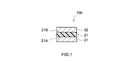
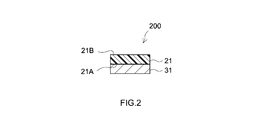
- the support layer may be at least one of a layer arranged in the sealant sheet; and a layer laminated on the sealant sheet. Therefore, the laminate containing the sealant sheet may be made of a sealant sheet having a laminated structure by itself, or may be a laminate having the sealant sheet and another layer different from the sealant sheet. Good.
- the support layer may be composed of two or more layers laminated or separately arranged, in which case the thickness t of the support layer is the total thickness of the two or more layers.
- the minimum width w of the support layer refers to the length (minimum length) of the minimum portion of the length of the support layer in the direction orthogonal to the direction in which the sealant sheet is pulled at the time of bonding. It is not to be interpreted in a limited way.
- the support layer may or may not have a longitudinal direction such as a band shape.
- the support layer has the formula (1): E ' ⁇ t ⁇ 1 ⁇ 10 4 [N / m]; satisfying.
- E' is the elastic modulus [MPa] of the support layer
- t is the thickness [ ⁇ m] of the support layer.
- the support layer has a thickness t of 0.025 to 0.10 mm.
- the thickness of the support layer is at least a predetermined value, it is easy to obtain a sealant sheet in which elongation at the time of sticking is suppressed. Further, since the thickness of the support layer is limited to a predetermined value or less, the sealant sheet has good flexibility and tends to improve the followability to the surface shape of the seal target portion.
- the elastic modulus E'of the support layer is 2500 MPa or more.
- the sealant sheet has a storage elastic modulus of 0.8 MPa or less at 25 ° C.
- the sealant sheet having the storage elastic modulus can exhibit good adhesion to an object, but tends to stretch easily with respect to tension. With respect to the sealant sheet having such a storage elastic modulus, the action effect of arranging the support layer disclosed herein (suppression of elongation at the time of attaching the sealant sheet) is effectively exhibited.
- the storage elastic modulus of the sealant sheet at 25 ° C. is the storage elastic modulus of the seal layer (sealant sheet surface layer) supported by the support base material. ..
- the sealant sheet is a photocurable sealant sheet.
- the photocurable sealant sheet can be well cured by light irradiation. Further, the photocurable sealant sheet is preferably used in a sealing construction in which the use of heat is not desirable because of the material to be sealed or the like.
- the sealant sheet (which is also a laminate containing the sealant sheet) comprises a support base material as the support layer and a seal layer disposed on at least one surface of the support base material. Be prepared.
- the supporting base material is preferably a resin film base material.
- the resin film substrate as the supporting substrate comprises a fluororesin film.
- the sealant sheet with a base material has a structure in which a seal layer is arranged on one side of a support base material.
- the back surface of such a base-based sealant sheet may be composed of a supporting base material. According to such a sealant sheet with a base material, the tact time can be shortened in addition to the improvement of productivity and the improvement of sealing quality as compared with the liquid sealant.
- the sealant sheet having the supporting base material (preferably a resin film base material, more preferably a fluororesin film base material) as described above, the sealant sheet has a thinner structure than the conventional one and is subjected to a sealing portion (for example, a cutting process). It is possible to prevent exposure and insufficient sealing (which can be the tip portion), and it is possible to obtain the required breaking voltage.
- a sealing portion for example, a cutting process
- a sealant sheet (sealant sheet with a base material) including a support base material and a seal layer arranged on at least one surface (preferably only one side) of the support base material.
- the sealant sheet preferably includes a resin film base material (more preferably a base material made of a fluororesin film) as the support base material.
- the support base material is a non-peelable support base material that is not intended to be separated from the seal layer during the period of use of the sealant sheet.
- the sealant sheet with a base material in which the seal layer is arranged on one side of the support base material may be one in which the back surface (opposite surface on the seal layer side) is composed of the support base material.
- a sealant sheet including a support base material and a seal layer arranged on at least one surface of the support base material
- the supporting base material is of the formula (1): E' ⁇ t ⁇ 1 ⁇ 10 4 [N / m]; and the formula (2): E' ⁇ t ⁇ w ⁇ 250 [N] ;. Satisfy at least one.
- E' is the elastic modulus [MPa] of the supporting base material
- t is the thickness of the supporting base material
- w is the minimum width [mm] of the supporting base material.
- the sealant sheet may be in the form of a sealant sheet with a release liner further comprising a release liner.
- the laminate comprises a release liner as the support layer.
- the release liner is arranged on one surface of the sealant sheet.
- the sealant sheet is attached to the object to be sealed in a state of being laminated on the release liner, and at that time, the elongation of the sealant sheet is suppressed.
- the sealant sheet with a release liner having the above configuration can be handled in the form of a sheet laminated on the release liner, and can be handled during transportation, processing, and storage as compared with other forms of curable sealants such as liquid sealants. It has excellent properties and quality retention, and can be easily and accurately placed at a desired location.
- a release liner containing a polyester resin film, a polyolefin resin film, a fluororesin film or paper is preferably used.
- a sealant sheet with a release liner includes a sealant sheet and a release liner arranged on one surface of the sealant sheet.
- the release liner is at least of the formula (1): E' ⁇ t ⁇ 1 ⁇ 10 4 [N / m]; and the formula (2): E' ⁇ t ⁇ w ⁇ 250 [N] ;. Satisfy one.
- E' is the elastic modulus [MPa] of the release liner
- t is the thickness of the release liner
- w is the minimum width [mm] of the release liner.
- the unit of the thickness of the release liner [mm] or [ ⁇ m] may be used depending on the unit of the formula.
- the sealant sheet with a release liner is a sealant sheet surface on which the first release liner is arranged in addition to the release liner (first release liner) as a support layer satisfying the above formulas (1) and / or (2).
- a second release liner, which is removed at the time of sticking, may be optionally provided on the opposite surface of the above.
- the sealant sheet is disclosed here by removing the second release liner to expose the surface of the sealant sheet, and attaching the sealant sheet to the object to be sealed in a state where the release liner (first release liner) satisfying the above formula is laminated.
- the effect of the technology to be used can be exhibited. This does not preclude that the two release liners both satisfy the above equation in the configuration including the two release liners.
- the sealant sheet preferably has a storage elastic modulus at 25 ° C. of 0.005 MPa or more and 0.8 MPa or less.
- a sealant sheet having a storage elastic modulus in this range can easily balance the adhesion to an object and the maintainability of the sheet shape.
- the sealant sheet is preferably made of a polysulfide sealant. By having the polysulfide structure, the sealant sheet can exhibit excellent oil resistance.
- the sealant sheet preferably contains a photobase generator. Since the sealant sheet containing the photobase generator is configured to promote the curing reaction by generating a base from the photobase generator by light irradiation, it suppresses the generation of bases from the photobase generator. Good storage stability can be exhibited by storing in the environment.
- a photobase generator for example, a compound containing a biguanide-type cation (a biguanide-based ionic photobase generator) can be preferably adopted. According to such a photobase generator, a sealant sheet having a good balance between good storage stability before use and good curability (photoanion curability) during use can be preferably realized.
- the sealant sheet comprises an epoxy group-containing polysulfide polymer (AB) having two or more epoxy groups in one molecule; and a thiol compound (C) having two or more thiol groups in one molecule; including.
- the sealant sheet may further contain the photobase generator (D).
- the sealant sheet of this embodiment may be referred to as a type (I) sealant sheet.
- the sealant sheets disclosed herein are, in some other embodiments, a thiol group-containing polysulfide polymer (AC) having two or more thiol groups in one molecule and an epoxy having two or more epoxy groups in one molecule. It may contain the compound (B).
- the sealant sheet may further contain the photobase generator (D).
- the sealant sheet of this embodiment may be referred to as a type (II) sealant sheet.
- All of the above-mentioned type (I) and (II) sealant sheets are cured in a state of being arranged at a desired position by an anion addition reaction of an epoxy group and a thiol group to improve the strength (for example, breaking strength). Can be made to.
- the cured sealant thus formed can exhibit excellent oil resistance due to the contribution of the polysulfide structure. Further, since the thickness of the cured product can be controlled by the thickness of the sealant sheet used, it is not necessary to adjust the coating thickness at the time of construction as in the case of applying the liquid sealant. Therefore, according to the above-mentioned sealant sheet, the polysulfide-based sealant can be easily and accurately applied.
- a step of preparing a laminate containing a sealant sheet for example, a sealant sheet with a supporting base material or a sealant sheet with a release liner; and attaching the laminate containing the sealant sheet to an object to be sealed.
- a sealing method including the steps and; is provided.
- the laminate is attached to the sealing object with a support layer satisfying at least one of the above formulas (1) and (2).
- the support layer By providing the support layer, the laminate containing the sealant sheet is prevented from stretching when the sealant sheet is attached to the object to be sealed. As a result, insufficient sealing and peeling due to tensile stress at the time of sticking are prevented.
- the above method includes, in an embodiment in which the sealant sheet is photocurable, a step of irradiating the sealant sheet with light before or at the time of attaching the laminate containing the sealant sheet to the object to be sealed. obtain.
- the sealant sheet may be irradiated with light through the release liner, or light irradiation may be performed after removing the release liner from the sealant sheet.
- the release liner can be removed from the sealant sheet before and after light irradiation.
- the curing speed of the sealant sheet after the curing treatment can be appropriately set, and light irradiation can be performed at an appropriate timing according to the appropriate setting to proceed with the curing of the sealant sheet.
- the timing of the light irradiation may be after the sealant sheet is attached to the sealing object, or before the sealant sheet is attached to the sealing object, and further, the sealing object may be irradiated.
- the light irradiation before and after the sticking includes a mode in which the light irradiation is performed while sticking the sealant sheet.
- the laminate containing the sealant sheet disclosed herein includes a support layer.
- the first aspect of the sealant sheet laminate disclosed herein is characterized by the support layer satisfying a property calculated from the product of elastic modulus and thickness.
- the support layer is based on the formula (1) :. E' ⁇ t ⁇ 1 ⁇ 10 4 [N / m] (1); To be satisfied.
- E' is the elastic modulus [MPa] of the support layer
- t is the thickness [ ⁇ m] of the support layer.
- the E'xt [N / m] in the formula (1) is preferably 3 ⁇ 10 4 N / m or more, more preferably 8 ⁇ 10 4 N / m or more, and further preferably 1 ⁇ 10 5 N / m. With the above, it may be 3 ⁇ 10 5 N / m or more, or 5 ⁇ 10 5 N / m or more.
- the upper limit of E'xt [N / m] can be set according to the application and the like, and is not limited to a specific range.
- E'xt [N / m] can be about 1 x 10⁶ N / m or less, and from the viewpoint of handleability based on good flexibility and followability to the surface shape of the seal target portion, It may be 8 ⁇ 10 5 N / m or less, 4 ⁇ 10 5 N / m or less, 2 ⁇ 10 5 N / m or less, or 1.5 ⁇ 10 5 N / m or less.
- the second aspect of the sealant sheet laminate disclosed herein is characterized by the support layer satisfying a property calculated from the product of elastic modulus, thickness and minimum width.
- the support layer is based on the formula (2) :. E' ⁇ t ⁇ w ⁇ 250 [N] (2) Satisfy.
- E' is the elastic modulus [MPa] of the support layer
- t is the thickness [mm] of the support layer
- w is the minimum width [mm] of the support layer.
- E' ⁇ t ⁇ w [N] in the formula (2) is preferably 800 N or more, more preferably 1000 N or more, further preferably 1200 N or more, particularly preferably 2000 N or more, and may be 3000 N or more. It may be 5000 N or more. Since the upper limit of E' ⁇ t ⁇ w [N] can be set according to the application and the like, it is not limited to a specific range. E' ⁇ t ⁇ w [N] can be about 1 ⁇ 10 5 N or less, and 5 ⁇ from the viewpoint of handleability based on good flexibility and followability to the surface shape of the seal target portion. 10 4 N may be less, may be a 3 ⁇ 10 4 N or less, may be 1.5 ⁇ 10 4 N or less, may be less 1 ⁇ 10 4 N may be below 8000 N, may be below 6000 N.
- the elastic modulus E'of the support layer is appropriately selected within a range that satisfies either one of the formulas (1) and (2), and is not limited to a specific range.
- the elastic modulus E'of the support layer is about 50 MPa or more, can be about 100 MPa or more, and from the viewpoint of suppressing the elongation of the sealant sheet, about 200 MPa or more is suitable, preferably about 100 MPa. It is 300 MPa or more, more preferably about 800 MPa or more.
- the elastic modulus E'of the support layer is about 1000 MPa or more, and from the viewpoint of suppressing the elongation of the sealant sheet, it can be about 1500 MPa or more, and about 2000 MPa or more is suitable and preferable.
- the upper limit of the elastic modulus E'of the support layer is, for example, 10000 MPa or less, and from the viewpoint of handleability based on good flexibility and followability to the surface shape of the sealing target portion, about 5000 MPa or less is appropriate. It is preferably about 4000 MPa or less, may be about 3600 MPa or less, may be about 3200 MPa or less, may be about 2700 MPa or less, may be about 2200 MPa or less, may be about 1600 MPa or less, and may be about 800 MPa or less.
- the elastic modulus E'of the support layer can be set and adjusted by selecting the material of the support layer or the like.
- the elastic modulus E'of the support layer is measured using a film viscoelasticity measuring device. Specifically, a support layer to be measured is prepared, cut into a width of 10 mm and a length of 50 mm, the distance between chucks is set to 20 mm, and the temperature is 1 Hz and the strain is 0.05%, and the temperature is -50 ° C to 10 ° C / min. The elastic modulus is measured at 23 ° C., and the elastic modulus is defined as E'[MPa].
- a product name "RSA3" manufactured by TA Instruments
- the stretching direction is preferably MD (Machine Direction). The examples described later are also measured by the same method.
- the thickness t of the support layer is appropriately selected within a range that satisfies either one of the formulas (1) and (2), and is not limited to a specific range.
- the thickness t of the support layer may be 1 ⁇ m or more, 2 ⁇ m or more, 5 ⁇ m or more, or 10 ⁇ m or more. From the viewpoint of suppressing the elongation of the sealant sheet, the thickness t of the support layer is preferably 20 ⁇ m or more (for example, 25 ⁇ m or more), more preferably 30 ⁇ m or more, 50 ⁇ m or more, or 70 ⁇ m or more.
- the upper limit of the thickness t of the support layer is approximately 1000 ⁇ m or less, may be 500 ⁇ m or less, or may be 300 ⁇ m or less.
- the thickness t of the support layer is preferably 200 ⁇ m or less, more preferably 150 ⁇ m or less, still more preferably 100 ⁇ m or less, and particularly preferably 80 ⁇ m or less. It may be 50 ⁇ m or less, or 30 ⁇ m or less. Needless to say, the thickness t [ ⁇ m] of the support layer can be displayed in units of mm by multiplying it by 1/1000.
- the thickness t of the support layer is the total thickness of those layers.
- the total thickness of the release liner and the support base material is the thickness t of the support layer.
- the minimum width w of the support layer is not particularly limited because an appropriate size can be adopted depending on the place of use, application, etc., and can be appropriately selected within a range that satisfies the formula (2), for example.
- the minimum width w of the support layer may be 1 mm or more, 2 mm or more, or 5 mm or more.
- the minimum width w of the support layer is preferably 7 mm or more, more preferably 10 mm or more, further preferably 15 mm or more, particularly preferably 20 mm or more, and may be 30 mm or more. It may be 40 mm or more, or 50 mm or more.
- the minimum width w of the support layer may be 500 mm or less, 300 mm or less, or 100 mm or less. From the viewpoint of handleability and the like, the minimum width w of the support layer may be 70 mm or less, 45 mm or less, 35 mm or less, 25 mm or less, 22 mm or less, 18 mm or less, 12 mm or less. However, it may be 7 mm or less.
- the minimum width w of the support layer may be the width of the support layer.
- the width of the sealant sheet can be the same as that of the support layer, the width of the sealant sheet (including the minimum width) can be the same as the width of the support layer (including the minimum width).
- the material of the support layer is not limited to a specific material.
- a resin film, a foam sheet, paper, cloth, a metal foil, a composite thereof, or the like can be used.
- Preferable examples include a material exemplified as a supporting base material described later and a material exemplified as a release liner.
- the sealant sheet laminate has a configuration comprising a support substrate and a seal layer disposed on at least one surface of the support substrate.
- the support base material corresponds to the support layer.
- the sealant sheet is provided with a support base material as a support layer, the items described below regarding the sealant sheet are applied to all the items including the composition (thickness, etc.), characteristics, and composition of the seal layer. Therefore, in this specification, the description of the matters overlapping with the sealant sheet with respect to the seal layer is omitted.
- the sealant sheet laminate is a sealant sheet with a release liner.
- the sealant sheet with a release liner includes a sealant sheet and a release liner arranged on one surface of the sealant sheet.
- the release liner corresponds to the support layer.
- FIGS. 1 to 3 Configuration examples of the sealant sheet laminate disclosed herein are shown in FIGS. 1 to 3.
- the sealant sheet laminate 100 shown in FIG. 1 is a sealant sheet with a release liner including the sealant sheet 21 and the release lines 31 and 32 arranged on both sides of the sealant sheet 21. More specifically, in the sealant sheet 21, each of the one surface (first surface) 21A and the other surface (second surface) 21B has a release liner 31, in which at least the sealant sheet 21 side is a release surface. Each is protected by 32.
- the release liner 31 satisfies the characteristics of the above formulas (1) and / or (2).
- the two release liners 31 and 32 are in contact with each surface of the sealant sheet 21 in a state where they can be peeled off from the sealant sheet 21, and can be peeled off with a light peeling force at an appropriate timing such as attachment to a seal object. Can be done.
- the sealant sheet laminate 200 shown in FIG. 2 is a sealant sheet with a release liner including a sealant sheet 21 and a release liner 31 arranged on one surface 21A of the sealant sheet 21. More specifically, the sealant sheet 21 has a structure in which one surface 21A is protected by a release liner 31 whose both sides are release surfaces, and when this is wound, the other surface of the sealant sheet 21 is protected. By contacting the surface 21B with the back surface of the release liner 31, the surface 21B can also be configured to be protected by the release liner 31.
- the release liner 31 of this embodiment satisfies the characteristics of the above formulas (1) and / or (2).
- the peeling liner 31 is in contact with the surface 21A of the sealant sheet 21 in a state where it can be peeled off from the sealant sheet 21, and can be peeled off with a light peeling force at an appropriate timing.
- the sealant sheet laminate 300 shown in FIG. 3 includes a sealant sheet 21, and the sealant sheet 21 includes a support base material 25 and seal layers 21a and 21b arranged on each surface of the support base material 25. It is a sealant sheet with a base material.
- the support base material 25 and the seal layers 21a and 21b are non-peelable laminates that are not intended to be separated from the seal layers 21a and 21b during the period of use of the sealant sheet.
- Such a support base material is also referred to as a non-peelable support base material.
- the supporting base material 25 of this embodiment satisfies the characteristics of the above formulas (1) and / or (2).
- the sealant sheet laminate 300 of this embodiment is in the form of a sealant sheet with a release liner, and one surface 21A (the surface of the seal layer 21a) of the sealant sheet 21 is peeled on both sides. It has a structure protected by a liner 31, and when it is wound, the other surface 21B of the sealant sheet 21 comes into contact with the back surface of the release liner 31, so that the surface 21B is also protected by the release liner 31. You can do it.
- the sealant sheet 21 of the configuration example shown in FIG. 3 had sealing layers 21a and 21b on both sides of the supporting base material 25, but is not limited to this, and only one surface of the supporting base material is sealed. It may have a layer. Further, although the sealant sheet laminate shown in FIG. 3 was provided with a release liner, the release liner may not be provided.
- the sealant sheet disclosed herein is preliminarily molded into a sheet shape, and can be arranged at a sealing target portion in the form of such a sheet shape.
- the sealant sheet is prepared by mixing a liquid sealant (for example, a liquid A containing a liquid polysulfide polymer and a liquid B containing a curing agent for the polysulfide polymer) to be applied to a portion to be sealed in a liquid form immediately before construction. It is clearly distinguished from the liquid sealant prepared together.
- a liquid sealant for example, a liquid A containing a liquid polysulfide polymer and a liquid B containing a curing agent for the polysulfide polymer
- the sealant sheet disclosed here can be cured by an appropriate curing means such as light irradiation or heating. That is, the sealant sheet disclosed herein may be a photocurable sealant sheet that is cured by light irradiation, or a thermosetting sealant sheet that is cured by heating.
- photocurable means that it can be cured by light irradiation.
- thermosetting means that it can be cured by heating.
- the heating may be heating at 30 ° C. or higher (for example, heating at 40 ° C. or higher, approximately 40 to 80 ° C.). Therefore, the photocurable sealant sheet and the thermosetting sealant sheet are terms that refer to the state before being completely cured.
- the sealant sheet is preferably photocurable. In that it has such curability, the sealant sheet disclosed herein is clearly distinguished from the cured sealant (sealant cured product).
- the sealant sheet disclosed herein can be grasped as a semi-cured sealant sheet that can be further cured after being placed at the sealing target portion.
- the sealant sheet disclosed here preferably has a shape retention property that can stably maintain the sheet shape at room temperature (for example, about 25 ° C.).
- the shape retention can also be grasped as resistance to plastic deformation such as flow.
- the storage elastic modulus of the sealant sheet at 25 ° C. (hereinafter, also simply referred to as “storage elastic modulus”) may be, for example, more than 0.005 MPa, preferably more than 0.01 MPa.
- the handleability and workability for example, cutability, blocking prevention property, reworkability, etc.) of the sealant sheet tend to be improved.
- the storage elastic modulus of the sealant sheet is preferably 0.02 MPa or more, for example, 0.05 MPa or more, 0.1 MPa or more, or 0.2 MPa or more.
- the upper limit of the storage elastic modulus is not particularly limited.
- the storage elastic modulus of the sealant sheet may be, for example, 2 MPa or less, 1 MPa or less, 0.8 MPa or less, 0.6 MPa or less, 0.5 MPa or less, and 0. It may be 4 MPa or less, 0.3 MPa or less, or 0.2 MPa or less.
- the storage elastic modulus is measured using a viscoelasticity tester under the conditions of a frequency of 1 Hz and a strain of 0.5%.
- a viscoelasticity tester a model name "ARES G2" manufactured by TA Instruments Japan Co., Ltd. or an equivalent product thereof can be used.
- the storage elastic modulus is more specifically measured by the method described in Examples described below.
- the storage elastic modulus of the sealant sheet means the storage elastic modulus of the sealant sheet before curing, and is distinguished from the storage elastic modulus of the sealant sheet (cured sealant) after curing, unless otherwise specified. Will be done.
- the storage elastic modulus of the sealant sheet typically means the storage elastic modulus before the sealant sheet is used, that is, before it is placed at the seal target portion by sticking or the like.
- the transmittance of the sealant sheet disclosed here may be, for example, more than 5%, more than 10%, more than 15%, or more than 20%.
- the upper limit of the transmittance is not particularly limited.
- the sealant sheet having a transmittance of a predetermined value or higher tends to realize uniform and efficient photocuring as a whole.
- the transmittance of the sealant sheet disclosed herein may be 100% or less, and may be 80% or less, 60% or less or 40% or less from a practical point of view.
- the sealant sheets disclosed herein can also be implemented in embodiments where the transmittance is 30% or less, 20% or less, or 15% or less. The transmittance is measured by the following method.
- the thickness of the sealant sheet is not particularly limited and can be selected according to the thickness of the desired cured sealant. From the viewpoint of seal reliability and the like, in some embodiments, the thickness of the sealant sheet may be, for example, 0.01 mm or more, 0.03 mm or more, 0.05 mm or more, 0.1 mm or more. However, it may be 0.15 mm or more.
- the sealant sheet disclosed herein can also be suitably implemented in an embodiment having a thickness of, for example, greater than 0.3 mm, greater than 0.5 mm, greater than 1 mm, or greater than 1.5 mm.
- the thickness of the sealant sheet may be, for example, 10 mm or less, 5 mm or less, 3 mm or less, 2 mm or less, 1 mm or less, 0.5 mm or less. It may be 0.3 mm or less. As the thickness of the sealant sheet decreases, the curability tends to improve. Reducing the thickness of the sealant sheet can be advantageous from the viewpoint of followability to the surface shape of the seal target portion and weight reduction.
- the material of the sealant sheet disclosed here is not particularly limited, and various materials can be used.
- sealant materials such as silicone-based, modified silicone-based, silylated acrylate-based, acrylic-based, acrylic urethane-based, polyurethane-based, polysulfide-based, polyisobutylene-based, and butyl rubber-based can be used.
- a polysulfide-based sealant material having excellent oil resistance is preferable.
- a polysulfide-based sealant material as a preferred example will be described, but the sealant disclosed herein is not limited to the polysulfide-based sealant.
- the sealant sheet comprises a polysulfide polymer (A).
- the polysulfide polymer (A) is a polymer having a repeating unit containing a dissulfide structure represented by —S—S—, and contributes to improving the oil resistance of the cured product formed from the sealant sheet.
- the type (I) sealant sheet disclosed herein contains the epoxy group-containing polysulfide polymer (AB) as the polysulfide polymer (A).
- the type (II) sealant sheet disclosed herein contains the thiol group-containing polysulfide polymer (AC) as the polysulfide polymer (A).
- the number of disulfide structures contained in one molecule of the polysulfide polymer (A) may be one or two or more. From the viewpoint of oil resistance of the cured product, a polysulfide polymer (A) containing an average of 3 or more disulfide structures per molecule can be preferably adopted.
- the average value of the number of dimethyl sulfide structures per molecule of the polysulfide polymer (A) (hereinafter, also referred to as the average number of dimethyl sulfide groups) may be, for example, 5 or more, 10 or more, 15 or more, 20 or more. The above may be sufficient.
- the upper limit of the average number of dimethyl sulfide groups is not particularly limited, but from the viewpoint of ease of manufacturing a sealant sheet (for example, ease of molding into a sheet shape), for example, it may be 100 or less, 70 or less, or 50 or less. Good.
- the dissulfide structure is preferably contained in the main chain of the polysulfide polymer (A). By including a disulfide structure in the main chain, a cured product having good elongation tends to be formed.
- the polysulfide polymer (A) preferably comprises a repeating unit represented by the following general formula (1). -R 1- OR 2- OR 3 -SS- (1)
- R 1 , R 2 , and R 3 are independently alkylene groups having 1 to 4 carbon atoms, preferably alkylene groups having 1 to 3 carbon atoms. More preferably, it is an alkylene group having 1 to 2 carbon atoms.
- the repeating unit (1) has a structure in which an ether structure and a disulfide structure are connected. According to the polysulfide polymer (A) having such a repeating unit (1), a cured product having excellent oil resistance and flexibility tends to be formed.
- the average value of the number of the repeating units (1) contained in one molecule of the polysulfide polymer (A) may be, for example, 5 or more, 10 or more, 15 or more, or 20 or more. Further, the average value may be, for example, 100 or less, 70 or less, or 50 or less.
- the polysulfide polymer (A) may have only one region in which the repeating unit (1) is continuous in one molecule, or may have two or more regions.
- the polysulfide polymer (A) may comprise at least one of the structures represented by the following general formula (2a) and the structure represented by the general formula (2b).
- R'in the general formulas (2a) and (2b) is an organic group having at least one (for example, about 1 to 5) epoxy groups.
- Structure of the general formula (2a) and (2b) formed, for example, a thiol having the structure represented by -CH 2 -SH, and an epoxy compound having a substituent R 'on the epoxy ring by the addition reaction of Can be done.
- Number of structures represented by the general formula (2a) or (2b) (If both the structure represented by the general formula (2a) and the structure represented by the general formula (2b) are included, the total number thereof. ) May be, for example, 1.1 or more, 1.3 or more, 1.5 or more, or 1.8 or more as the average value per molecule of the polysulfide polymer (A). It may be 0 or more, or more than 2.0. Further, the average value may be, for example, 15 or less, 10 or less, 7.0 or less, or 5.0 or less.
- the structures represented by the above general formulas (2a) and (2b) can be formed by an addition reaction of a thiol group and an epoxy group.
- the polysulfide polymer (A) containing the structures represented by the general formulas (2a) and (2b) is, for example, a thiol group-containing polysulfide having a disulfide structure and a thiol group in one molecule, and 2 in one molecule. It can be a reaction product of the above epoxy compound having an epoxy group or a modified product thereof.
- the weight average molecular weight (Mw) of the thiol group-containing polysulfide as a precursor of the polysulfide polymer (A) is not particularly limited, and may be, for example, 500 or more, 800 or more, 1000 or more, or 1000 or more. Well, it may be over 2000. According to the thiol group-containing polysulfide having a higher Mw, a sealant sheet that gives a cured product with better elongation tends to be formed. In some embodiments, the Mw of the thiol group-containing polysulfide may be, for example, greater than 2500, greater than 3000, or greater than 3500.
- the Mw of the thiol group-containing polysulfide may be, for example, 30,000 or less, and may be 10,000 or less. From the viewpoint of handleability and reactivity with the epoxy compound, in some embodiments, the Mw of the thiol group-containing polysulfide may be, for example, less than 9000, less than 8000, less than 7500, less than 7000. It may be less than 6500.
- Mw of a polymer such as a thiol group-containing polysulfide, an epoxy group-containing polysulfide, or a polysulfide polymer (A) described later is subjected to gel permeation chromatography (GPC) using tetrahydrofuran (THF) as a mobile phase.
- GPC gel permeation chromatography
- THF tetrahydrofuran
- the nominal value described in a catalog, literature, or the like may be used.
- the thiol group-containing polysulfide preferably contains the disulfide structure in the main chain.
- the sealant sheet containing a reaction product of a thiol group-containing polysulfide having a disulfide structure in the main chain and an epoxy compound having two or more epoxy groups in one molecule or a modified product thereof, the polysulfide polymer (A). Good cured products tend to be formed.
- the number of disulfide structures contained in one molecule of thiol group-containing polysulfide may be, for example, 3 or more, 5 or more, or 10 or more as the average value (average number of disulfide groups) of the entire thiol group-containing polysulfide used.
- the upper limit of the average number of dimethyl sulfide groups is not particularly limited, but from the viewpoint of ease of manufacturing a sealant sheet (for example, ease of molding into a sheet shape), for example, it may be 100 or less, 70 or less, or 50 or less. Good.
- the number of thiol groups contained in the thiol group-containing polysulfide as a precursor of the polysulfide polymer (A) may be one or two or more per molecule of the thiol group-containing polysulfide. .. From the viewpoint of facilitating the realization of a sealant sheet suitable for improving the strength of the cured product and shortening the curing time, a thiol group-containing polysulfide having an average number of thiol groups contained in one molecule of more than 1 is preferable.
- the average value of the number of thiol groups per molecule of thiol group-containing polysulfide used may be, for example, 1.1 or more, 1.3 or more, or 1.5 or more. It may be 8 or more, 2 or more, or 2 or more.
- the upper limit of the average number of thiol groups is not particularly limited, but from the viewpoint of flexibility of the cured product, for example, it may be 15 or less, 10 or less, 7 or less, or 5 or less.
- Polysulfide having an average number of thiol groups of 2 or more can also be grasped as a thiol compound (C) having 2 or more thiol groups in one molecule.
- the thiol group is preferably arranged at the end of the thiol group-containing polysulfide.
- an epoxy group-containing polysulfide polymer having an epoxy group at the terminal can be suitably formed.
- the thiol group-containing polysulfide used may have a thiol group at one end of the main chain, may have a thiol group at both ends of the main chain, and may have a thiol group at both ends of the main chain. It may further have a thiol group, or it may be a mixture of any combination thereof.
- a thiol group-containing polysulfide having a thiol group at both ends of the main chain that is, a thiol polysulfide having both ends.
- a sealant sheet containing the polysulfide polymer (A) synthesized by using both terminal thiol polysulfides a cured product having a good balance between strength and elongation tends to be formed.
- the proportion of bi-terminal thiol polysulfide in the total thiol group-containing polysulfide used may be, for example, greater than 50%, greater than 70%, greater than 90%, by weight. It may be more than 95%, more than 98%, or substantially 100%.
- Both terminal thiol polysulfides are preferably represented by the following general formula (3).
- R 1 , R 2 , and R 3 are independently alkylene groups having 1 to 4 carbon atoms, preferably alkylene groups having 1 to 3 carbon atoms, and more preferably. It is an alkylene group having 1 to 2 carbon atoms.
- N in the general formula (3) means that the formula amount of the compound of the general formula (3) is, for example, 500 or more and 10000 or less, or 800 or more and less than 9000, or 1000 or more and less than 8000, or more than 1000 and less than 8000, or 2000. Can be an integer chosen to be in the range greater than and less than 7500.
- the compound represented by the general formula (3) is, for example, a thiol group in which R 1 is C 2 H 4 , R 2 is CH 2 , and R 3 is C 2 H 4.
- the contained polysulfide can be preferably adopted.
- n in the general formula (3) may be, for example, 3 to 70, 5 to 60, 7 to 50, or 10 to 50.
- the sealant sheet of the type (I) contains, as the polysulfide polymer (A), an epoxy group-containing polysulfide polymer (AB) having two or more epoxy groups in one molecule. Further, it may contain a thiol compound (C) having two or more thiol groups in one molecule. In some preferred embodiments, the sealant sheet may further comprise a photobase generator (D). The sealant sheet of such an embodiment may or may not further contain a polysulfide polymer (A) that does not correspond to the epoxy group-containing polysulfide polymer (AB). Further, the sealant sheet of the above aspect may or may not further contain an epoxy compound (B) that does not correspond to the epoxy group-containing polysulfide polymer (AB).
- the average value of the number of epoxy groups per molecule of the epoxy group-containing polysulfide polymer (AB) (hereinafter, also referred to as the average number of epoxy groups) can be, for example, about 2 or more and 20 or less. From the viewpoint of the flexibility of the cured product, the average number of epoxy groups may be, for example, 15 or less, 10 or less, 7 or less, or 5 or less. In some embodiments, the average number of epoxy groups may be 4 or less and 3 or less. The average number of epoxy groups is typically 2 or more, and may be more than 2 or 2.5 or more from the viewpoint of curability and strength of the cured product. In some embodiments, the average number of epoxy groups may be, for example, 3 or more, and may be 4 or more.
- the epoxy group contained in the epoxy group-containing polysulfide polymer (AB) is preferably arranged at the end of the epoxy group-containing polysulfide polymer (AB). According to such an epoxy group-containing polysulfide polymer (AB), a cured product having good elongation tends to be formed.
- the sealant sheet disclosed herein may contain an epoxy group-containing polysulfide polymer (AB) having two or more epoxy groups at one end of the main chain, and one or more epoxys at both ends of the main chain, respectively. It may contain an epoxy group-containing polysulfide polymer (AB) having a group, or both of them.
- the epoxy group-containing polysulfide polymer (AB) having an epoxy group at one end of the main chain may have a functional group other than the epoxy group at a terminal different from the end having the epoxy group.
- the functional group other than the epoxy group may be, for example, a thiol group, an amino group, a hydroxyl group or the like.
- the sealant sheet disclosed herein preferably contains at least an epoxy group-containing polysulfide polymer (AB) having epoxy groups at both ends of the main chain.
- the epoxy group-containing polysulfide polymer (AB) reacts, for example, the thiol group-containing polysulfide as described above with an epoxy compound having two or more epoxy groups in one molecule so that the amount of epoxy groups becomes excessive.
- the epoxy compound may be a bifunctional epoxy compound having two epoxy groups in one molecule, or a polyfunctional epoxy compound having three or more epoxy groups in one molecule.
- Epoxy compounds may be used alone or in combination of two or more. From the viewpoint of operability when reacting with a thiol group-containing polysulfide, an epoxy compound liquid at room temperature can be preferably used in some embodiments.
- the bifunctional epoxy compound has a structure in which a bisphenol A type epoxy resin, a bisphenol F type epoxy resin, and a hydrogenated bisphenol A type epoxy resin (that is, the aromatic ring of the bisphenol A type epoxy resin is converted into a cycloalkyl ring by hydrogenation).
- polyfunctional epoxy compound examples include novolak type epoxy resin, glycidylamine type epoxy resin, biphenyl type epoxy resin, triphenylmethane type epoxy resin, dicyclopentadiene type epoxy resin, glycerin type epoxy resin, trimethylolpropane type epoxy resin, and N. , N, N', N'-tetraglycidyl-m-xylene diamine, 1,3-bis (N, N-diglycidylaminomethyl) cyclohexane, polyglycerol polyglycidyl ether, etc., but is not limited thereto. ..
- the number of epoxy groups contained in one molecule of the polyfunctional epoxy compound is at least 3 or more, and may be 4 or more or 5 or more.
- the number of epoxy groups contained in one molecule of the polyfunctional epoxy compound is usually 10 or less, and may be 8 or less, or 6 or less.
- a bifunctional epoxy compound can be preferably used as the epoxy compound.
- the use of a bifunctional epoxy compound can be advantageous to obtain a sealant sheet that gives a cured product that exhibits suitable elongation.
- the bifunctional epoxy compound may be used alone or in combination of two or more.
- an epoxy compound containing a carbon ring structure having a 5-membered ring or more in the molecule can be preferably adopted. According to the sealant sheet using the bifunctional epoxy compound having such a structure, a cured product having high strength and good elongation tends to be formed.
- the carbon ring structure having five or more members may be, for example, a benzene ring, a naphthalene ring, a cyclohexyl ring, or the like.
- Examples of the epoxy compound containing such a carbocyclic structure include bisphenol A type epoxy resin, bisphenol F type epoxy resin, hydrogenated bisphenol A type epoxy resin, hydrogenated bisphenol F type epoxy resin, biphenyl type epoxy resin and the like.
- a bisphenol F type epoxy resin can be used as the bifunctional epoxy compound.
- one or more polyfunctional epoxy compounds can be used in combination with the bifunctional epoxy compound or in place of the bifunctional epoxy resin.
- the strength of the cured product can be improved by using a polyfunctional epoxy compound.
- a polyfunctional epoxy compound having a repeating unit containing an epoxy group (that is, a polymer type) can be used, and for example, a novolak type epoxy resin can be preferably adopted.
- the novolac type epoxy resin include a phenol novolac type epoxy resin and an o-cresol novolac type epoxy resin.
- the use of a novolak type epoxy resin can be advantageous for obtaining a sealant sheet that gives a cured product having high strength and good elongation. By using a novolak type epoxy resin having a lower molecular weight, the elongation of the cured product tends to be improved.
- a phenol novolac type epoxy resin that is liquid at room temperature can be preferably adopted.
- any suitable catalyst is adopted as long as the effect obtained by the technique disclosed herein is not significantly impaired. You may.
- known basic catalysts such as 2,4,6-triaminomethylphenol, triethylamine, and 1,8-diazabicyclo [5.4.0] undec-7-ene can be appropriately selected and used.
- the amount used when using a basic catalyst is not particularly limited, and can be set so that the catalyst function is appropriately exhibited.
- the amount of the basic catalyst used is, for example, 1 part by weight or less based on 100 parts by weight of the total amount of the thiol group-containing polysulfide and the epoxy compound having two or more epoxy groups in one molecule.
- it is suitable to be 0.5 parts by weight or less, 0.2 parts by weight or less, 0.1 parts by weight or less, or 0.08 parts by weight or less. From the viewpoint of improving the storage stability of the sealant sheet, it is advantageous that the amount of the basic catalyst used is not too large.
- the amount of the basic catalyst used with respect to 100 parts by weight of the total amount can be, for example, 0.07 parts by weight or less, 0.05 parts by weight or less, or 0.03 parts by weight or less. It may be 0.02 parts by weight or less.
- the lower limit of the amount of the basic catalyst used with respect to 100 parts by weight of the total amount is not particularly limited, and may be, for example, 0.001 part by weight or more, and may be 0.005 part by weight or more.
- the above reaction can be carried out by mixing a thiol group-containing polysulfide, an epoxy compound having two or more epoxy groups in one molecule, and a catalyst used as needed in an appropriate reaction vessel. ..
- the thiol group-containing polysulfide, the bifunctional epoxy compound, the polyfunctional epoxy compound, and the catalyst are mixed in a suitable reaction vessel.
- the method of supplying each material to the reaction vessel and the mixing order are not particularly limited, and an appropriate reactant can be selected so as to be formed.
- the above reaction conditions can be appropriately set as long as the effects obtained by the techniques disclosed herein are not significantly impaired.
- the reaction can proceed at a reaction temperature of, for example, 0 ° C.
- the reaction temperature may be, for example, 20 ° C to 100 ° C, 30 ° C to 100 ° C, or 40 ° C to 100 ° C, in consideration of reaction controllability and reaction efficiency. It may be 60 ° C. to 100 ° C.
- the reaction time is not particularly limited, and can be selected from the range of, for example, 10 minutes to 720 hours (preferably 1 hour to 240 hours).
- the reaction involves a first heating step performed at, for example, a temperature of 60 ° C. to 120 ° C. (preferably 70 ° C. to 110 ° C.) and 40 ° C. to 80 ° C. (preferably 50 ° C. to 70 ° C.).
- the second heating step which is carried out at the same temperature as above, can be carried out in this order.
- the second heating step is preferably performed at a temperature lower than that of the first heating step.
- the heating time in the first heating step can be, for example, 10 minutes or more, usually 30 minutes or more, and may be 1 hour or more. In some preferred embodiments, the heating time in the first heating step can be selected, for example, from the range of 10 minutes to 24 hours (preferably 30 minutes to 12 hours, more preferably 1 hour to 6 hours).
- the heating time in the second heating step can be, for example, 3 hours or more, usually 6 hours or more, and may be 24 hours or more. In some preferred embodiments, the heating time in the second heating step can be selected from, for example, in the range of 3 hours to 720 hours (preferably 48 hours to 500 hours, more preferably 72 hours to 300 hours).
- the heating time in the second heating step is preferably longer than the heating time in the first heating step.
- the heating step may be divided into three or more steps and performed step by step.
- the ratio of the thiol group-containing polysulfide used and the epoxy compound used in the synthesis of the epoxy group-containing polysulfide polymer (AB) by the above reaction is included in the epoxy compound with respect to the total number of thiol groups contained in the thiol group-containing polysulfide.
- the ratio of the total number of epoxy groups that is, the equivalent ratio of epoxy groups / thiol groups (hereinafter, also referred to as epoxy / thiol ratio) can be set to be a value larger than 1.
- the epoxy / thiol ratio can be, for example, 1.05 or higher, and may be 1.1 or higher.
- the epoxy / thiol ratio may be, for example, more than 1.2, more than 1.4, more than 1.5, more than 1.7. But it may be.
- the epoxy / thiol ratio can be, for example, less than 7.0, less than 5.0, less than 4.5, or less than 4.0.
- the epoxy / thiol ratio may be, for example, less than 3.5, less than 3.2, less than 3.0, less than 2.5, from the standpoint of improving elongation of the cured product. It may be less than 2.0, less than 1.8, or less than 1.8.
- the amount of the epoxy compound having two or more epoxy groups in one molecule is not particularly limited.
- the amount of the epoxy compound used can be set, for example, so that any of the epoxy / thiol ratios described above can be achieved.
- the amount of the epoxy compound used can be, for example, 1 part by weight or more, and usually 3 parts by weight or more, based on 100 parts by weight of the thiol group-containing polysulfide. It may be 5 parts by weight or more, or 7 parts by weight or more.
- the amount of the epoxy compound used with respect to 100 parts by weight of the thiol group-containing polysulfide can be, for example, 50 parts by weight or less, usually 30 parts by weight or less, and 20 parts by weight or less. It may be 15 parts by weight or less.
- the sealant sheet of type (II) contains, as the polysulfide polymer (A), a thiol group-containing polysulfide polymer (AC) having two or more thiol groups in one molecule. Further, it may contain an epoxy compound (B) having two or more thiol groups in one molecule. In some preferred embodiments, the sealant sheet may further comprise a photobase generator (D).
- the sealant sheet of such an embodiment may or may not further contain a polysulfide polymer (A) that does not correspond to a thiol group-containing polysulfide polymer (AC). Further, the sealant sheet of the above aspect may or may not further contain a thiol compound (C) that does not correspond to the thiol group-containing polysulfide polymer (AC).
- the average number of thiol groups in a thiol group-containing polysulfide polymer (AC) is typically 2 or more, and may be more than 2.
- the upper limit of the average number of thiol groups is not particularly limited, but from the viewpoint of the flexibility of the cured product, 10 or less is usually suitable, and may be 7 or less, 5 or less, 4 or less, 3 or less, or 2 It may be 8.8 or less or 2.4 or less.
- the thiol group contained in the thiol group-containing polysulfide polymer (AC) is preferably arranged at the end of the thiol group-containing polysulfide polymer (AC).
- a cured product having good elongation tends to be formed.
- a thiol group-containing polysulfide polymer (AC) having one or more thiol groups at both ends of the main chain is preferable, and a thiol group-containing polysulfide polymer (AC) having one thiol group at both ends of the main chain is more preferable. preferable.
- the thiol group-containing polysulfide polymer (AC) for example, the above-mentioned epoxy group-containing polysulfide polymer (AB) and a thiol compound having two or more thiol groups in one molecule have an excessive amount of thiol groups. Those obtained by reacting in this way can be used.
- the thiol compound may be a bifunctional thiol compound having two thiol groups in one molecule, or a polyfunctional thiol compound having three or more thiol groups in one molecule.
- the thiol compound may be used alone or in combination of two or more.
- a bifunctional thiol compound can be preferably used from the viewpoint of obtaining a sealant sheet that gives a cured product showing suitable elongation.
- the thiol compounds to be reacted with the epoxy group of the epoxy group-containing polysulfide polymer (AB) 50% by weight or more, 70% by weight or more, or 90% by weight or more can be a bifunctional thiol compound. Only the bifunctional thiol compound may be used as the thiol compound.
- the thiol compound to be reacted with the epoxy group-containing polysulfide polymer (AB) for example, one or more selected from the materials that can be used as the thiol compound (C) described later can be used.
- the reaction between the epoxy group-containing polysulfide polymer (AB) and the thiol compound can proceed in the same manner as the reaction between the thiol group-containing polysulfide and the epoxy compound described above.
- the ratio of the epoxy group-containing polysulfide used to the thiol compound used in the synthesis of the thiol group-containing polysulfide polymer (AC) by the above reaction is included in the thiol compound with respect to the total number of epoxy groups contained in the epoxy group-containing polysulfide.
- the ratio of the total number of thiol groups can be set to be less than 1. From the viewpoint of improving the strength of the cured product and the like, in some embodiments, the epoxy / thiol ratio can be, for example, 0.95 or less, 0.9 or less, or 0.85 or less.
- the epoxy / thiol ratio may be, for example, 0.1 or more, and usually 0.2 or more is appropriate. In some embodiments, the epoxy / thiol ratio may be, for example, 0.3 or higher, 0.5 or higher, 0.6 or higher, or 0.7 or higher, from the viewpoint of improving the elongation of the cured product. ..
- the amount of the thiol compound having two or more thiol groups in one molecule is not particularly limited.
- the amount of the thiol compound used can be set, for example, so that any of the epoxy / thiol ratios described above can be achieved.
- the amount of the thiol compound used can be, for example, 1 part by weight or more, and usually 3 parts by weight or more, based on 100 parts by weight of the epoxy group-containing polysulfide. It may be 5 parts by weight or more, or 7 parts by weight or more.
- the amount of the thiol compound used with respect to 100 parts by weight of the epoxy group-containing polysulfide can be, for example, 50 parts by weight or less, usually 30 parts by weight or less, and 20 parts by weight or less. It may be 15 parts by weight or less.
- thiol group-containing polysulfide polymer (AC) in a type (II) sealant sheet for example, as a material that can be used as a precursor of a polysulfide polymer (A), the above-mentioned thiol group-containing polysulfide (preferably both terminal thiol polysulfide). ) May be used.
- the sealant sheet comprises an epoxy compound (B).
- the epoxy compound (B) contained in the sealant sheet a compound having two or more epoxy groups in one molecule can be used without particular limitation.
- one or more selected from the group consisting of various bifunctional epoxy compounds and polyfunctional epoxy compounds exemplified as materials that can be used for preparing an epoxy group-containing polysulfide polymer (AB) can be used.
- the epoxy compound (B) having an epoxy equivalent in the range of 50 g / eq or more and 600 g / eq or less can be preferably adopted.
- the epoxy equivalent may be, for example, 100 g / eq or more, 120 g / eq or more, 150 g / eq or more, or 400 g / eq or less, 300 g / eq or less, or 200 g / eq. It may be less than or equal to eq.
- the epoxy equivalent increases, the storage stability before use tends to improve, while the curability during use tends to decrease.
- the epoxy equivalent means the number of grams of a compound containing 1 equivalent of an epoxy group, and can be measured in accordance with JIS K7236: 2001. Alternatively, the nominal value described in a catalog, literature, or the like may be used.
- the average number of epoxy groups of the epoxy compound (B) can be, for example, about 2 or more and 10 or less. From the viewpoint of the flexibility of the cured product, the average number of epoxy groups may be, for example, 7 or less, 5 or less, 4 or less, or less than 4. In some embodiments, the average number of epoxy groups may be 3 or less, 2.5 or less, or 2.2 or less.
- the epoxy compound (B) only one kind or two or more kinds of bifunctional epoxy compounds may be used. According to such a configuration, it is easy to obtain a sealant sheet that gives a cured product showing suitable elongation.
- the sealant sheet comprises a thiol compound (C).
- a thiol compound (C) contained in the sealant sheet a compound having two or more thiol groups in one molecule can be used without particular limitation.
- trimetylolpropanthithiopropionate also known as trimetylolpropanetris (3-mercaptopropionate)
- pentaeristol tetrakisthiopropionate ethylene glycol bisthioglycolate
- 1,4-butanediol bis 1,4-butanediol bis.
- Thioglycolate trimethylolpropane tristhioglycolate, pentaeristol tetrakisthioglycolate, di (2-mercaptoethyl) ether, 1,4-butanedithiol, 1,5-dimercapto-3-thiapentane, 1,8- Dimercapto-3,6-dioxaoctane, 1,3,5-trimercaptomethylbenzene, 4,4'-thiodibenzenethiol, 1,3,5-trimercaptomethyl-2,4,6-trimethylbenzene, 2,4,6-Trimercapto-s-triazine, 2-dibutylamino-4,6-dimercapto-s-triazine, pentaerythritol tetrakis (3-mercaptopropionate), dipentaerythritol hexa-3-mercaptopropio Nate and the like can be mentioned, but the present invention is not limited
- thiol compound (C) Commercially available products of the thiol compound (C) include, for example, JERmate QX11, QX12, JER Cure QX30, QX40, QX60, QX900, Capcure CP3-800 manufactured by Mitsubishi Chemical Co., Ltd .; OTG, EGTG manufactured by Yodo Chemical Co., Ltd. TMTG, PETG, 3-MPA, TMTP, PETP; TEMPIC, TMMP, PEMP, PEMP-II-20P, DPMP manufactured by Sakai Chemical Co., Ltd .; Karenz MT PE1, Karenz MT BD1, Karenz MT NR1 manufactured by Showa Denko KK. TPMB, TEMB; and the like, but are not limited thereto. Each of these compounds may be used alone, or two or more thereof may be mixed and used.
- the average number of thiol groups in the thiol compound (C) can be, for example, about 2 or more and 10 or less. From the viewpoint of the flexibility of the cured product, the average number of thiol groups may be, for example, 7 or less, 5 or less, 4 or less, or less than 4. In some embodiments, the average number of thiol groups may be 3 or less, 2.5 or less, or 2.2 or less.
- the thiol compound (C) only one kind or two or more kinds of bifunctional thiol compounds may be used. According to such a configuration, it is easy to obtain a sealant sheet that gives a cured product showing suitable elongation.
- the thiol compound (C) includes a compound having a primary thiol group (hereinafter, also referred to as a primary thiol compound), a compound having a secondary thiol group (secondary thiol compound), and a compound having a tertiary thiol group (3). Any of the secondary thiol compounds) can be used. From the viewpoint of curability when using the sealant sheet, a primary thiol compound can be preferably adopted. Further, from the viewpoint of controlling the curing rate of the sealant sheet before use and preservability, a secondary or higher thiol compound (that is, a secondary thiol compound and / or a tertiary thiol compound) can be preferably adopted.
- a thiol compound having two primary thiol groups in one molecule may be referred to as a primary bifunctional thiol compound, and a thiol compound having two secondary thiol groups in one molecule may be referred to as a secondary bifunctional thiol compound.
- a thiol compound having two primary thiol groups in one molecule may be referred to as a primary bifunctional thiol compound, and a thiol compound having two secondary thiol groups in one molecule may be referred to as a secondary bifunctional thiol compound.
- a primary thiol compound and a secondary or higher thiol compound can be used in combination.
- the storage stability of the sealant sheet before use and the curability at the time of use can be suitably compatible with each other.
- the weight ratio of the primary thiol compound to the total weight of the primary thiol compound and the secondary or higher thiol compound is not particularly limited, and may be, for example, 5% by weight or more, preferably 15% by weight or more. It is preferably 25% by weight or more, may be 35% by weight or more, and may be, for example, 95% by weight or less, preferably 75% by weight or less, and may be 60% by weight or less. , 45% by weight or less.
- thiol compound (C) those having a thiol equivalent in the range of 45 g / eq or more and 450 g / eq or less are preferably adopted in consideration of the balance between the storage stability of the sealant sheet before use and the curability at the time of use. obtain.
- the thiol equivalent may be, for example, 60 g / eq or more, 70 g / eq or more, 80 g / eq or more, or 350 g / eq or less, 250 g / eq or less, 200 g / eq. It may be eq or less, or 150 g / eq or less.
- the storage stability before use tends to improve, while the curability during use tends to decrease.
- the sum of the products of the thiol equivalents and the weight fractions of each thiol compound (C) is in the above range.
- the thiol equivalent means the number of grams of a compound containing 1 equivalent of a thiol group, and can be measured by an iodine titration method. Alternatively, the nominal value described in a catalog, literature, or the like may be used.
- the ratio of the epoxy group equivalent to the thiol group equivalent that can be contained in the sealant sheet that is, the epoxy / thiol ratio of the sealant sheet is.
- the epoxy / thiol ratio of the sealant sheet may be, for example, approximately 0.1 or more and 10 or less, 0.2 or more and 5 or less, 0.3 or more and 3 or less, or 0.5 or more and 2 or less. Good.
- the epoxy / thiol ratio When the epoxy / thiol ratio is at least one of the above-mentioned lower limit values and less than or equal to the upper limit value, a cured product having both strength and elongation in a well-balanced manner tends to be formed.
- the epoxy / thiol ratio may be, for example, 0.6 or greater, 0.7 or greater, or 0.8 or greater, and 1.7 or less, 1.5 or less, or 1.2 or less. You can.
- the amount of the thiol compound (C) that can be contained in the sealant sheet is not particularly limited.
- the amount of the thiol compound (C) contained in the sealant sheet can be set so as to realize, for example, any of the above-mentioned epoxy / thiol ratios.
- the amount of the thiol compound (C) relative to 100 parts by weight of the epoxy group-containing polysulfide polymer (AB) can be, for example, 0.05 parts by weight or more, and may be 0.1 parts by weight or more. It may be 0.3 parts by weight or more, 0.5 parts by weight or more, for example, 10 parts by weight or less, 5 parts by weight or less, 3 parts by weight or less, or 1 part by weight or less. May be.
- the amount of the epoxy compound (B) that can be contained in the sealant sheet is not particularly limited.
- the amount of the epoxy compound (B) contained in the sealant sheet can be set so as to realize, for example, any of the above-mentioned epoxy / thiol ratios.
- the amount of the epoxy compound (B) relative to 100 parts by weight of the thiol group-containing polysulfide polymer (AC) can be, for example, 0.05 parts by weight or more, and may be 0.1 parts by weight or more. It may be 0.3 parts by weight or more, 0.5 parts by weight or more, 1 part by weight or more, for example, 15 parts by weight or less, 10 parts by weight or less, 5 parts by weight. It may be less than a part by weight.
- the sealant sheet disclosed herein preferably contains one or more of various photoreaction catalysts capable of initiating and promoting a curing reaction by light irradiation.
- a photoreaction catalyst may be referred to as a photoreaction initiator or photopolymerization initiator.
- a preferred example of the photoreaction catalyst is a photobase generator (D).
- the sealant sheet comprises a photobase generator (D).
- the photobase generator (D) an agent that generates a base by light irradiation is used.
- photobase generators include ⁇ -aminoacetophenone compounds; oxime ester compounds; acyloxyimino groups, N-formylated aromatic amino groups, N-acylated aromatic amino groups, nitrobenzyl carbamate groups, alcooxybenzyl carbamate. Examples thereof include a compound having a substituent such as a group; a compound having a biguanide type cation; and the like.
- the ⁇ -aminoacetophenone compound those having two or more nitrogen atoms are particularly preferable.
- the photobase generator may be used alone or in combination of two or more.
- a commercially available product may be used as the photobase generator.
- Examples of commercially available photobase generators include WPBG-018 (9-anthramethyl N, N'-diethyl carbamate) and WPBG-027 ((E) -1- [3] manufactured by Wako Pure Chemical Industries, Ltd.
- WPBG-082 guanidium 2- (3-benzoylphenyl) propionate
- WPBG-140 (1- (anthraquinone-2-yl) ethylimidazole carboxylate)
- WPBG-266 (1,2-diisopropyl-3- [bis (dimethylamino) methylene] guanidium 2- (3-benzoylphenyl) propionate
- WPBG-300 (1,2-dicyclohexyl-4,4,5,5-) Tetramethylbiguanidium n-butyltriphenylborate
- WPBG-345 (1,2-dicyclohexyl-4,4,5,5-tetramethylbiguanidiumtetrakis (3-fluorophenyl) boronate) and the like. ..
- an ionic photobase generator having a biguanide-type cation is preferable because the base generated by light irradiation can effectively promote the anion addition reaction between the epoxy group and the thiol group.
- biguanide-type cations include alkyl biguanide, cycloalkyl bigadinium, cycloalkyl-alkylbiguadinium and the like.
- the anion paired with the biguanide cation in the photobase generator can be, for example, a borate anion.
- Examples of commercially available products of this type of photobase generator include the above-mentioned WPBG-300 and WPBG-345.
- an anion paired with a biguanide-type cation in a photobase generator is a carboxylate anion.
- the above-mentioned WPBG-266 can be preferably adopted.
- the amount of the photobase generator used can be set so that the desired effect of use can be obtained.
- the amount of the photobase generator used is the total amount of the epoxy group-containing polysulfide polymer (AB) and the thiol compound (C) (in the case of a type (I) sealant sheet) or the thiol group-containing polysulfide polymer.
- the total amount of (AC) and the epoxy compound (B) (in the case of the type (II) sealant sheet) can be, for example, 0.01 part by weight or more with respect to 100 parts by weight, and the curability of the sealant sheet can be improved.
- the amount of the photobase generator used is usually preferably 3 parts by weight or less, more preferably 2 parts by weight or less, based on 100 parts by weight of the total amount, from the viewpoint of raw material cost and the like. It may be 1 part by weight or less, 0.7 parts by weight or less, 0.5 parts by weight or less, or 0.3 parts by weight or less.
- the sealant sheet disclosed herein may contain a sensitizer.
- a sensitizer By using the sensitizer, it is possible to increase the utilization efficiency of the irradiated light and improve the sensitivity of the photoreaction catalyst (for example, the photobase generator (D)).
- the photosensitizer can be appropriately selected from known materials and used. Non-limiting examples of photosensitizers include benzophenone, 4-methylbenzophenone, 3-benzoylbiphenyl, 4- (4-methylphenylthio) benzophenone, methyl 2-benzoylbenzoate, 4-phenylbenzophenone, 4,4.
- the amount used can be set so as to obtain a desired sensitizing effect.
- the amount of the photosensitizer used may be, for example, 0.001 part by weight or more, for example 0.001 part by weight or more, based on 100 parts by weight of the total amount of the epoxy compound (B) and the thiol compound (C). It may be .005 parts by weight or more, 0.01 parts by weight or more, or 0.05 parts by weight or more.
- the upper limit of the amount of the photosensitizer used is not particularly limited, but from the viewpoint of controlling the curing speed of the sealant sheet and preservability, usually 10 parts by weight or less is suitable, and 5 parts by weight or less may be used, and 1 weight by weight. It may be 5 parts or less, 0.5 parts by weight or less, or 0.3 parts by weight or less.
- the sealant sheet disclosed herein may further contain any compound that may help suppress the curing reaction, as long as other properties are not significantly impaired. By using such a compound, the storage stability of the sealant sheet before use can be improved.
- the storage stabilizer may be, for example, an organic acid, an inorganic acid, which is liquid or solid at room temperature, and an oligomer, a polymer, a borate ester, or a phosphoric acid ester containing an acidic group in the molecule, and is a functional other than the acidic group. It may have a group.
- Examples thereof include, but are not limited to, sulfuric acid, acetic acid, adipic acid, tartaric acid, fumaric acid, barbituric acid, boric acid, pyrogallol, phenol formaldehyde, carboxylic acid anhydride and the like.
- the storage stabilizer one type may be used alone or two or more types may be used in combination as appropriate.
- the amount of the storage stabilizer used is not particularly limited and can be set so as to obtain a desired effect.
- Preferable examples of storage stabilizers include boric acid esters and phosphoric acid esters.
- Boric acid esters are boric acid esters that are liquid or solid at room temperature.
- Examples of phosphoric acid esters include ethyl phosphate, butyl phosphate, propyl phosphate, -2-ethylhexyl phosphate, dibutyl phosphate, di-di (2-ethylhexyl) phosphate, oleyl phosphate, ethyldiethyl phosphate and the like. However, it is not limited to these.
- the sealant sheet disclosed herein may contain a filler, if necessary. This can improve one or both of the breaking strength of the cured product and the elongation at break.
- the filler can also help regulate the storage modulus of the sealant sheet. In addition, proper use of the filler can improve the shape retention and workability of the sealant sheet.
- the filler used is not particularly limited, and any suitable filler may be used as long as the effects obtained by the techniques disclosed herein are not significantly impaired.
- the filler may be used alone or in combination of two or more.
- Examples of materials that make up the filler include talc, silica, glass, carbon black, alumina, clay, mica, aluminum hydroxide, magnesium hydroxide, calcium carbonate, magnesium carbonate, barium sulfate, titanium dioxide, barium titanate, and titanium. Includes, but is not limited to, strontium acid acid, calcium titanate, magnesium titanate, bismuth titanate, boron nitride, aluminum borate, barium zirconate, calcium zirconate and the like. Among them, preferred examples include talc, silica, glass and calcium carbonate.
- the content of the filler is not particularly limited and can be selected so as to obtain suitable characteristics.
- the content of the filler may be, for example, 1% by weight or more of the entire sealant sheet, 5% by weight or more, 10% by weight or more, or 15% by weight or more from the viewpoint of obtaining a higher effect of use. It may be 20% by weight or more, or 25% by weight or more.
- the content of the filler can be, for example, less than 50% by weight of the entire sealant sheet, and is usually less than 40% by weight from the viewpoint of improving the moldability into the sheet shape and the elongation of the cured product. It is suitable and may be less than 35% by weight. In some embodiments, the content of the filler may be less than 30% by weight or less than 25% by weight.
- the average particle size of the filler is not particularly limited.
- the average particle size is usually preferably 100 ⁇ m or less, and preferably 50 ⁇ m or less. As the average particle size becomes smaller, the effect of improving one or both of the breaking strength and the elongation at break of the cured product tends to improve.
- the average particle size of the filler may be, for example, 30 ⁇ m or less, 20 ⁇ m or less, 15 ⁇ m or less, 10 ⁇ m or less, or 5 ⁇ m or less.
- the average particle size of the filler may be, for example, 0.1 ⁇ m or more, 0.2 ⁇ m or more, 0.5 ⁇ m or more, or 1 ⁇ m or more. It is possible that the average particle size is not too small, which is advantageous from the viewpoint of handleability and dispersibility of the filler.
- the average particle size of the filler is the particle size at which the cumulative particle size based on the volume is 50% in the particle size distribution obtained by the measurement based on the laser diffraction / scattering method, that is, the 50% volume average particle size. (50% median diameter).
- a filler made of a material having a refractive index in the range of 1.56 or more and less than 1.62 can be preferably used.
- a glass filler having a refractive index in the above range can be used.
- the range of the refractive index is equal to or close to the refractive index (typically about 1.60) of the polysulfide polymer (A). Therefore, according to the filler having the refractive index in the above range, the decrease in the transmittance of the sealant sheet due to the blending of the filler tends to be suppressed as compared with the filler having the refractive index outside the above range.
- the sealant sheet has a certain degree of transmittance, it becomes easy to observe the seal target portion through the sealant sheet. This can be advantageous from the viewpoint of positioning property when the sealant sheet is arranged at a predetermined position.
- the sealant sheet disclosed herein is a combination of a filler having a refractive index in the range of 1.56 or more and less than 1.62 (for example, a glass filler) and a filler having a refractive index outside the above range (for example, talc). May be used.
- the proportion of the filler having a refractive index in the above range in the total amount of the filler contained in the sealant sheet can be, for example, 10% by weight or more, 25% by weight or more, preferably 45% by weight or more. It may be 60% by weight or more, 85% by weight or more, or 100% by weight.
- a filler made of a material having a refractive index in the range of 1.56 or more and 1.61 or less, or 1.57 or more and 1.60 or less may be more preferably adopted.
- the refractive index can be measured using generally known methods such as the minimum declination method, the critical angle method, and the V-block method. The measurement can be performed using, for example, a multi-wavelength Abbe refractometer DR-M4 (manufactured by ATAGO) or the like. Alternatively, the nominal value described in a catalog, literature, or the like may be used.
- the sealant sheet disclosed herein may contain a curing agent for the sealant sheet.
- a curing agent for the sealant sheet.
- a material having a functional group that reacts with an epoxy group can be used.
- imidazole-based curing agents for example, 2-methylimidazole, 1-isobutyl-2 methylimidazole, 2-ethyl-4-methylimidazole, 1-cyanoethyl-2-undecylimidazolium trimerite, etc.
- amine-based curing agents for example, 2-methylimidazole, 1-isobutyl-2 methylimidazole, 2-ethyl-4-methylimidazole, 1-cyanoethyl-2-undecylimidazolium trimerite, etc.
- One or more selected from agents for example, aliphatic amine-based curing agents, aromatic amine-based curing agents), acid anhydride-based curing agents, dicyanamide-based curing agents, polyamide-based curing agents and the like can be used. ..
- agents for example, aliphatic amine-based curing agents, aromatic amine-based curing agents), acid anhydride-based curing agents, dicyanamide-based curing agents, polyamide-based curing agents and the like can be used. ..
- examples of preferable curing agents from the viewpoint of reactivity at room temperature and mild heating conditions include imidazole-based curing agents and amine-based curing agents.
- An imidazole-based curing agent is particularly preferable.
- the sealant sheet disclosed herein may contain other optional components as long as the effects obtained by the techniques disclosed herein are not significantly impaired.
- optional components include colorants such as dyes and pigments, dispersants, plasticizers, softeners, flame retardants, antioxidants, UV absorbers, antioxidants, light stabilizers and the like. , Not limited to these.
- the sealant sheet disclosed here may further contain a polymer or oligomer (hereinafter, also referred to as an arbitrary polymer) other than the above for the purpose of improving the adhesion to the sealing target portion, for example.
- a polymer or oligomer hereinafter, also referred to as an arbitrary polymer
- the content of the optional polymer is preferably 10 parts by weight or less, more preferably 5 parts by weight or less, based on 100 parts by weight of the polysulfide polymer (A). It is more preferably 1 part by weight or less.
- It may be a sealant sheet that does not substantially contain such an optional polymer.
- substantially not containing a certain component means that the component is not contained at least intentionally unless otherwise specified.
- the content of the organic solvent may be, for example, 5% or less, 2% or less, 1% or less, or 0.5% or less of the sealant sheet on a weight basis. Well, it does not have to contain substantially an organic solvent.
- the content of the organic solvent may be 0%.
- the organic solvent is intended to react with other components in the sealant sheet, such as toluene, cyclohexanone, trichloroethane, etc. (particularly, epoxy group-containing polysulfide and a curing agent that can be used if necessary). Ingredients that have not been added.
- the type (I) sealant sheet may contain a thiol compound (C) having an Mw of 1000 or less, preferably 600 or less, more preferably 400 or less (hereinafter, also referred to as a low molecular weight thiol compound).
- the content of the low molecular weight thiol compound may be, for example, 0.1% by weight or more of the total amount of the entire thiol compound (C) and the epoxy group-containing polysulfide polymer (AB) on a weight basis, and is 0.3. It may be 0.5% by weight or more, or 0.5% by weight or more.
- the low molecular weight thiol compound may exhibit a function of enhancing the tack of the sealant sheet disclosed herein.
- the temporary fixing property of the sealant sheet arranged at the seal target portion to the seal target portion can be improved.
- the temporary fixing property means a property of suppressing floating or misalignment of the sealant sheet from the sealing target portion until the sealant sheet arranged at the sealing target portion is cured.
- the low molecular weight thiol compound reacts with light irradiation and is incorporated into the cured product.
- the content of the low molecular weight thiol compound may be less than 0.1% by weight of the total amount of the total thiol compound (C) and the epoxy group-containing polysulfide polymer (AB) on a weight basis. , 0.05% by weight, and may not be substantially contained.
- the sealant sheet disclosed herein may have a tack on the surface and may be temporarily fixed to the seal target portion even in such an embodiment.
- the type (II) sealant sheet may contain an epoxy compound (B) having an Mw of 1000 or less, preferably 600 or less, more preferably 400 or less (hereinafter, also referred to as a low molecular weight epoxy compound).
- the content of the low molecular weight epoxy compound may be, for example, 0.1% by weight or more of the total amount of the entire epoxy compound (B) and the thiol group-containing polysulfide polymer (AC) on a weight basis, and is 0.3. It may be 0.5% by weight or more, or 0.5% by weight or more.
- the low molecular weight epoxy compound like the low molecular weight thiol compound, may exhibit a function of enhancing the tack of the sealant sheet disclosed herein.
- the content of the low molecular weight epoxy compound may be less than 0.1% by weight of the total amount of the total epoxy compound (B) and the thiol group containing polysulfide polymer (AC) on a weight basis. , 0.05% by weight, and may not be substantially contained.
- the sealant sheet disclosed herein may have a tack on the surface and may be temporarily fixed to the seal target portion even in such an embodiment.
- the sealant sheet disclosed herein may include a supporting substrate.
- a sealant sheet may include a supporting substrate and a sealing layer disposed on at least one surface (eg, both sides) of the supporting substrate.
- Such a sealant sheet with a supporting base material tends to be excellent in stickability and workability to the object to be sealed, and also excellent in handleability.
- the tact time can be shortened in addition to the improvement of productivity and the sealing quality as compared with the liquid sealant.
- the conventional liquid sealant needs to be cured (typically dried) until there is no tack on the surface of the sealant after applying the liquid sealant to the part to be sealed, which shortens the process work time. Had a limit.
- the sealant sheet in which the support base material is arranged on one side the back surface thereof is composed of the support base material and does not flow like a liquid. After the application, the curing (typically drying) step can be omitted, and the tact time can be shortened.
- the sealant sheet having the support base material (for example, a base material containing a resin film) is thinner than the conventional liquid sealant sheet (for example, the thickness of the sealant sheet is less than 5.0 mm and further less than 3.0 mm). Therefore, the required performance including the sealing function (various performances required for the sealing portion, for example, the durability of the sealing) can be suitably satisfied and further improved.
- the sealant sheet having the support base material it is possible to prevent the sealing portion (for example, the tip portion which has been cut and processed) from being exposed or insufficient sealing by the structure thinner than the conventional one. Further, the required breaking voltage can be obtained, or the breaking voltage can be improved.
- edge glow is a structure made of CFRP at the time of a lightning strike, for example, when a carbon reinforced fiber plastic (CFRP) material cut into a desired shape or size is used for an aircraft or the like.
- CFRP carbon reinforced fiber plastic
- the CFRP end is sealed with a sufficient thickness (for example, a thickness of about 10 mm), but according to the technology disclosed here. , Sufficient edge glow prevention can be obtained without impairing other performance.
- a resin film, a foam sheet, paper, cloth, a metal foil, a composite thereof, or the like can be used.
- the material of the supporting base material include a polyolefin film made of polyethylene (PE), polypropylene (PP), etc., a polyester film made of polyethylene terephthalate (PET), fluorine made of polytetrafluoroethylene (PTFE), etc.
- Various resin films such as resin films and polyvinyl chloride films; various fibrous substances (natural fibers such as hemp and cotton, synthetic fibers such as polyester and vinylon, semi-synthetic fibers such as acetate, etc.) alone. Alternatively, woven fabrics and non-woven fabrics made by blending or the like; etc.
- a base film containing a (self-supporting or independent) resin film that can independently maintain its shape can be preferably used as the supporting base material.
- a polyester film such as a PET film is preferable.
- the "resin film” means a resin film (of voidless) having a non-porous structure and typically containing substantially no bubbles. Therefore, the resin film is a concept that is distinguished from foam films and non-woven fabrics.
- the resin film may have a single-layer structure or a multi-layer structure having two or more layers.
- the resin film may be unstretched or stretched (for example, uniaxially stretched or biaxially stretched).
- a substrate containing a resin film is preferably used as the supporting substrate.
- the sealant sheet provided with the supporting base material containing the resin film it is easy to shorten the tact time, and the thin structure makes it easy to prevent the sealing part from being exposed or insufficient sealing, and a sufficient voltage at break is obtained.
- Cheap As the resin film, one or more of the resin films exemplified above can be used.
- the resin film material it is preferable to use a material having appropriate flexibility and high insulating properties.
- the resin film include a fluororesin film such as PTFE and a polyimide resin film.
- the supporting base material for example, resin film
- additives such as light stabilizers, antioxidants, antistatic agents, colorants (dye, pigment, etc.), fillers, slip agents, antiblocking agents, etc. Can be blended according to the above.
- the blending amount of the additive is not particularly limited, and can be appropriately set according to the intended use and the like.
- the transmittance of the support base material may be, for example, more than 5%, more than 10%, more than 15%, or more than 20%.
- 50% or more is suitable, preferably 70% or more, and 90% or more may be used from the viewpoint of curability by light irradiation.
- the upper limit of the transmittance of the supporting base material is not particularly limited, and may be 100%, or may be 80% or less, 60% or less, or 40% or less from a practical point of view.
- the supporting substrate disclosed herein can also be implemented in embodiments where the transmittance is 30% or less, 20% or less, or 15% or less. The transmittance is measured by the same method as the method for measuring the transmittance of the sealant sheet.
- the thickness of the supporting base material is not particularly limited and can be selected according to the purpose of use, the mode of use, and the like.
- the thickness of the supporting base material may be, for example, about 1000 ⁇ m or less, about 300 ⁇ m or less, about 100 ⁇ m or less, preferably about 80 ⁇ m or less, about 50 ⁇ m or less, and about 30 ⁇ m. It may be less than or equal to, and may be 15 ⁇ m or less.
- the thickness of the supporting base material becomes smaller, the flexibility of the sealant sheet and the ability to follow the surface shape of the seal target portion tend to improve.
- the thickness of the supporting base material is limited from the viewpoint of curability by light irradiation.
- the thickness of the supporting base material may be 1 ⁇ m or more, 2 ⁇ m or more, 5 ⁇ m or more, or 10 ⁇ m or more.
- the thickness of the supporting substrate is preferably 20 ⁇ m or greater (eg 25 ⁇ m or greater), more preferably 30 ⁇ m or greater, 50 ⁇ m or greater, or 70 ⁇ m or greater.
- the thickness of the supporting base material can also be specified in relation to the thickness of the seal layer.
- the ratio of the thickness T2 of the support base material to the thickness of the seal layer (when the seal layers are provided on both sides of the support base material, the total thickness of the seal layers) T1 (T2 / T1) is, for example, approximately 0.001.
- the above is appropriate, and from the viewpoint of suppressing elongation when the sealant sheet is attached, it is preferably about 0.01 or more, may be about 0.03 or more, may be 0.07 or more, and may be 0.10 or more. But it may be.
- the above ratio (T2 / T1) is, for example, about 1 or less, preferably about 0.5 or less, from the viewpoint of followability to the surface shape of the seal target portion, handleability, seal reliability, and the like. , It may be about 0.3 or less, about 0.2 or less, or 0.15 or less. In the embodiment in which the sealing layer is provided on each surface of the supporting base material, the thicknesses of the two sealing layers may be the same or different.
- the type (I) sealant sheet contains a combination of an epoxy group-containing polysulfide polymer (AB) and a thiol compound (C) (for example, the low molecular weight thiol compound described above).
- a thiol compound (C) for example, the low molecular weight thiol compound described above.
- an epoxy group-containing polysulfide polymer (AB) is prepared; a thiol compound (C), a photobase generator (D) and a filler are added to the epoxy group-containing polysulfide polymer (AB).
- the epoxy group-containing polysulfide polymer (AB) is a reaction product of a thiol group-containing polysulfide, a bifunctional epoxy compound, and a polyfunctional epoxy compound
- preparing the above mixture can be carried out by preparing the thiol group-containing polysulfide and the bifunctional compound.
- a reaction product of an epoxy compound and a polyfunctional epoxy compound and to add a thiol compound (C), a photobase generator (D) and a filler to the reaction product and mix them; in this order. obtain.
- the fillers may be mixed together during the preparation of the above reactants.
- the type (II) sealant sheet contains a thiol group-containing polysulfide polymer (AC) in combination with an epoxy compound (B) (for example, the low molecular weight epoxy compound described above).
- an epoxy compound (B) for example, the low molecular weight epoxy compound described above.
- a thiol group-containing polysulfide polymer (AC) is prepared; an epoxy compound (B), a photobase generator (D) and a filler are added to the thiol group-containing polysulfide polymer (AC).
- thiol group-containing polysulfide polymer (AC) is a thiol-modified product of an epoxy group-containing polysulfide polymer
- preparing the above mixture means that the thiol group of a compound having two or more thiol groups in one molecule is converted into the epoxy group.
- a thiol group-containing polysulfide polymer (AC) by reacting with the epoxy group of the contained polysulfide polymer (AB); the thiol group-containing polysulfide polymer (AC), the epoxy compound (B), and the photobase generator (D)
- fillers may be included in this order. Alternatively, the fillers may be mixed together during the preparation of the above reactants.
- Examples of the device that can be used for mixing the reaction product and the additive component include a closed kneading device such as a Banbury mixer, a kneader, a two-roll mill, a three-roll mill, or a batch kneading device; a single-screw extruder, two. Examples include, but are not limited to, continuous kneading devices such as shaft extruders.
- the press molding may be a normal pressure press or a vacuum press. From the viewpoint of preventing air bubbles from getting caught in the sheet and suppressing heat denaturation of the mixture, vacuum press molding or calendar molding can be preferably applied in some embodiments.
- the obtained sealant sheet is configured as a sealant sheet with a release liner as shown in FIG. 1 or 2 by laminating it on the release liner.
- a sheet may be formed by applying the above mixture onto a release liner or a supporting base material using a conventional coater such as a gravure roll coater.
- the sealant sheet with a support base material is configured as a sealant sheet with a release liner by laminating a release liner on the surface thereof.
- the sealant sheet laminate disclosed herein can be a sealant sheet with a release liner comprising a release liner. According to the structure in which the surface of the sealant sheet is protected by the release liner in this way, contamination such as deformation due to external force and adhesion of dust can be prevented. Further, the sealant sheet can be handled in a state of being laminated on the release liner, and can be attached to the object to be sealed in a state of being laminated on the release liner. Such a sealant sheet with a release liner is excellent in handleability and quality retention, and can be easily and accurately placed at a desired location.
- the release liner is not particularly limited, and for example, a release liner having a release treatment layer on the surface of the release liner base material; and a low level such as a fluoropolymer (PTFE, etc.) and a polyolefin resin (PE, PP, etc.).
- a release liner made of an adhesive resin film is included.
- a release liner having a release treatment layer on the release liner base material can be preferably adopted.
- the peeling treatment layer may be formed by surface-treating the peeling liner base material with a peeling treatment agent.
- the stripping agent may be a known stripping agent such as a silicone-based stripping agent, a long-chain alkyl-based stripping agent, a fluorine-based stripping agent, or molybdenum sulfide (IV).
- a release liner having a release treatment layer with a silicone-based release treatment agent can be preferably adopted.
- the thickness and forming method of the peeling treatment layer are not particularly limited, and can be set so that appropriate peeling property is exhibited on the peeling surface of the peeling liner.
- a plastic film is typically a non-porous sheet, a concept that distinguishes it from, for example, non-woven fabrics (ie, does not include non-woven fabrics).
- polyester resins such as PET and polyolefin resins such as PE and PP.
- a release liner base material formed from any one or a mixture of two or more of these resins can be used.
- a preferable release liner base material includes a polyester-based resin film (for example, PET film) formed from a polyester-based resin.
- the plastic film used as the above-mentioned release liner base material may be any of a non-stretched film, a uniaxially stretched film, and a biaxially stretched film. Further, the plastic film may have a single-layer structure or a multi-layer structure including two or more sub-layers.
- the plastic film is a release liner containing antioxidants, antioxidants, heat stabilizers, light stabilizers, UV absorbers, colorants such as pigments and dyes, lubricants, fillers, antistatic agents, nucleating agents, etc.
- a known additive that can be used for the base material may be blended. In the multi-layered plastic film, each additive may be blended in all sublayers or only in some sublayers.
- the release liner may have a light transmittance of 20% or more in the wavelength range of 350 to 450 nm.
- the light transmittance of the release liner is preferably 25% or more, more preferably 30% or more, still more preferably 35% or more, and 50% or more, from the viewpoint of curability by light irradiation through the release liner. It may be 70% or more, 90% or more.
- at least the release liner arranged on the light irradiation side may have the above-mentioned light transmittance.
- the two release liners may have the above-mentioned light transmittance, or only one (light irradiation side) may have the above-mentioned light transmittance. Good.
- the upper limit of the light transmittance of the release liner is not particularly limited, but is preferably 80% or less from the viewpoint of visibility.
- the presence or absence of such a release liner can be easily confirmed on the sealant sheet, and it is possible to prevent forgetting to remove the release liner, for example, after the sealant sheet is attached to the object to be sealed.
- the light transmittance is preferably 75% or less, more preferably 70% or less, still more preferably 65% or less.
- the light transmittance of the release liner in the wavelength range of 350 to 450 nm is measured by the following method. That is, the light transmittance (wavelength 365 nm) of the release liner is determined by measuring the spectrum of the release liner using a UV-vis spectrum measuring device (manufactured by Shimadzu Corporation, product name "UV-2550") and having a wavelength of 350 to 450 nm. The light transmittance in the region can be obtained. In the present specification, for convenience, a value at a wavelength of 365 nm may be used as the light transmittance (wavelength 365 nm) of the release liner.
- a value at a wavelength of 365 nm may be used as the light transmittance (wavelength 365 nm) of the release liner.
- the light transmittance of the release liner should be adjusted by selecting the material (resin material) of the release liner base material, the type and amount of additives (for example, colorants such as pigments), and the selection of the release treatment agent. Can be done.
- the release liner when the release liner has the above-mentioned light transmittance of a predetermined value or more, the main region of the whole region to be laminated with the sealant sheet (more than 50% of the whole, for example, 70% or more) has the above-mentioned light transmittance. It means to have.
- the sealant sheet is photocurable
- the release liner has the above-mentioned light transmittance over substantially the entire surface of the release liner from the viewpoint of homogeneous and efficient photocuring of the sealant sheet laminated on the release liner. It is preferable to have 20% or more, preferably 20 to 80%).
- substantially the entire surface of the release liner surface means that the surface of the release liner does not have the above-mentioned light transmittance when the area of the entire area to be laminated with the sealant sheet is 100%, for example, due to an arrangement such as printing. It means that the area ratio of the area is less than 5% of the whole.
- the area ratio of the region having no light transmittance may be less than 3% or less than 1%.
- the ratio of the region having no light transmittance to the total area of the region laminated with the sealant sheet on the surface of the release liner is not particularly limited, for example, about 30% or less, and further 10. It can be set as appropriate within the range of% or less.
- the release liner is within the range of the light transmittance over almost the entire surface of the release liner due to the uniform curing of the sealant sheet laminated on the release liner. It is preferable to have a uniform light transmittance.
- the light transmittance of the entire region to be laminated with the sealant sheet is preferably in the range of ⁇ 10% (for example, ⁇ 5%).
- the release liner having the above-mentioned light transmittance can be preferably produced by using an appropriate colorant.
- Conventionally known pigments and dyes can be used as the colorant.
- Pigments include, for example, zinc carbonate, zinc oxide, zinc sulfide, talc, kaolin, calcium carbonate, titanium oxide, silica, lithium fluoride, calcium fluoride, barium sulfate, alumina, zirconia, iron oxide, and iron hydroxide.
- Chromium oxide type Chromium hydroxide type, Spinel type firing type, Chromic acid type, Chrome vermilion type, Navy blue type, Cobalt blue type, Aluminum powder type, Bronze powder type, Silver powder type, Calcium phosphate and other inorganic pigments Phthalocyanine-based, azo-based, condensed azo-based, azolake-based, anthraquinone-based, perylene-perinone-based, flavon, indigo-based, thioindigo-based, isoindolinone-based, azomethine-based, dioxazine-based, quinacridone-based, aniline black-based, triphenylmethane Among organic pigments such as those based on carbon black and those based on carbon black, those that can easily achieve a predetermined transmittance are preferably used.
- the dye for example, among azo dyes, anthraquinone, quinophthalone, styryl, diphenylmethane, triphenylmethane, oxazine, triazine, xanthan, methane, azomethin, acrydin, and diazine, those that can easily achieve a predetermined transmittance are preferable. Used. As the colorant, one type may be used alone or two or more types may be used in combination as appropriate.
- the light transmittance is realized by including an appropriate colorant in any of the layers constituting the release liner (the release liner base material, the release treatment layer, or any layer different from them).
- the release liner substrate comprises the colorant.
- the release liner having a light transmittance in a predetermined range disclosed herein has, for example, black, gray, white, red, blue, yellow, while having a transmission rate equal to or higher than a predetermined range. It may exhibit one or more colors such as green, yellow-green, orange, purple, gold, silver, and pearl. From the viewpoint of visibility, it is preferably gray, red, blue, yellow, green, yellow-green, orange, and purple, and from the viewpoint of achieving both transparency and visibility, it is blue and green. Is more preferable, and blue is particularly preferable.
- blue means a color having a visible spectrum wavelength range of 360 nm or more and less than 480 nm
- green means a color having a visible spectrum wavelength range of 480 nm or more and less than 560 nm.
- the first release liner and the second release liner may have the same material and composition, and may have different materials and configurations. It may have.
- the sealant sheet with a release liner disclosed here is a peelable laminate of a release liner and a sealant sheet. Therefore, the peeling force of the release liner with respect to the sealant sheet is preferably limited to a predetermined value or less.
- the peeling force of the release liner is approximately 3N / 50mm or less, more preferably 1N / 50mm or less, 0.70N / 50mm or less, and 0.50N / 50mm. It may be as follows.
- the lower limit of the peeling force of the peeling liner is preferably 0.01 N / 50 mm or more, and may be 0.05 N / 50 mm or more from the viewpoint of protection by the peeling liner and prevention of floating.
- the peeling force of the peeling liner can be adjusted by a peeling treatment or the like on the surface of the peeling liner.
- the release force of each release liner is preferably different from the viewpoint of release workability, or may be designed to the same extent.
- the peeling force of the peeling liner is measured under the conditions of a sealant with a peeling liner cut to a length of 150 mm and a width of 50 mm, a tensile speed of 300 mm / min, and a peeling angle of 180 ° in an atmosphere of 23 ° C. and 50% RH. To.
- the thickness of the release liner is not particularly limited, and may be, for example, about 10 ⁇ m to 500 ⁇ m. From the viewpoint of the strength and handleability of the release liner, the thickness of the release liner is preferably 20 ⁇ m or more (for example, 25 ⁇ m or more), preferably 30 ⁇ m or more, 35 ⁇ m or more, 40 ⁇ m or more, or 45 ⁇ m or more. It may be 50 ⁇ m or more, and may be 70 ⁇ m or more.
- the large thickness of the release liner is also advantageous from the viewpoint of preventing deformation of the sealant sheet attached to the object to be sealed.
- the thickness of the release liner is preferably 300 ⁇ m or less, preferably 200 ⁇ m or less, more preferably 150 ⁇ m or less, and further preferably 100 ⁇ m or less. Particularly preferably, it is 80 ⁇ m or less, 50 ⁇ m or less, or 30 ⁇ m or less.
- the thicknesses of the first release liner and the second release liner are preferably different from the viewpoint of release workability, or even if they are the same. Good.
- the thickness of the release liner can also be specified in relation to the thickness of the sealant sheet.
- the ratio of the thickness T R of the release liner to the thickness T S of the sealant sheet (T R / T S) is and conformability to the surface shapes of the sealing target portion, handleability, from the viewpoint of sealing reliability, e.g. Approximately 1 or less is appropriate, preferably approximately 0.5 or less, may be approximately 0.3 or less, may be approximately 0.2 or less, and may be 0.15 or less.
- the sealant sheet is photocurable, it is also advantageous in terms of efficient light curing sealant sheet that satisfies the above ratio (T R / T S).
- the material of the portion to be sealed using the sealant sheet disclosed herein is not particularly limited.
- the material may be, for example, a metal, a resin, a composite material thereof, or the like, and more specifically, iron, an iron alloy (carbon steel, stainless steel, chrome steel, nickel steel, etc.), aluminum, an aluminum alloy, nickel, or the like.
- Tungsten copper, copper alloy, titanium, titanium alloy, silicon and other metal or semi-metal materials
- polyolefin resin polycarbonate resin, acrylic resin, acrylonitrile resin (PAN) and other resin materials
- alumina silica, sapphire, silicon nitride, Ceramic materials such as tantalum nitride, titanium carbide, silicon carbide, gallium nitride, gypsum; glass materials such as aluminosilicate glass, soda lime glass, soda aluminosilicate glass, quartz glass; laminates and composites thereof; etc. .
- the metal or metalloid material include a light metal such as aluminum and titanium, or an alloy containing the light metal as a main component.
- Examples of aluminum alloys include duralumin (eg, duralumin A2024, duralumin A2017, etc.).
- Examples of the composite include carbon fiber reinforced plastic (CFRP) and glass fiber reinforced plastic (FRP). The techniques disclosed herein are preferably utilized for articles or parts having seals made of such materials.
- the sealant sheet disclosed here exhibits the form of a non-liquid (that is, solid) sheet in a temperature range of about 25 ° C., unlike the liquid sealant, the operator is thick when arranging the sealant at the sealing target portion. There is no need to control the temperature.
- the sealant sheet can be cut into a desired outer shape in advance and then placed at the sealing target portion (typically, the sealant sheet can be attached by using the tack of the sealant sheet). Is. Alternatively, the roll-shaped sealant sheet may be unwound and attached to the target location, and the excess sealant sheet may be separated.
- the sealant sheet disclosed here By using the sealant sheet disclosed here, problems such as dripping, uneven coating, and protrusion during application of the liquid sealant can be fundamentally solved, and the working time can be significantly shortened.
- the sealant sheet is used in a space where light rays that affect photocuring are blocked or restricted, such as in a dark room, until it is used, that is, before the light irradiation step. It is preferable to store it in a dark place).
- the sealant sheet at the time of storage may be in the form of a sheet body of a sealant sheet with a release liner (which may have a shape according to an application or the like) or a roll body of a sealant sheet with a release liner.
- the techniques disclosed herein include a step of preparing a laminate containing a sealant sheet (eg, a sealant sheet with a supporting substrate or a sealant sheet with a release liner); and a step of attaching the laminate containing the sealant sheet to an object to be sealed.
- a sealant sheet eg, a sealant sheet with a supporting substrate or a sealant sheet with a release liner
- attaching the laminate containing the sealant sheet to an object to be sealed Includes sealing methods including and; In this method, since the laminate is attached to the seal target portion with a support layer satisfying the above formulas (1) and / or (2), elongation is suppressed when the sealant sheet is attached. ..
- the method may include a step of light-irradiating the sealant sheet before, after, or at the same time as attaching the laminate containing the sealant sheet to the object to be sealed.
- the sealant sheet may be irradiated with light through the release liner, or light irradiation may be performed after removing the release liner from the sealant sheet.
- the release liner can be removed from the sealant sheet before and after light irradiation.
- the sealant sheet is cured by light irradiation.
- the sealant sheet can be cured by irradiating light through the release liner in a form laminated on the release liner.
- the epoxy group and thiol contained in the sealant sheet are generated by generating a base from the photobase generator (D) by irradiating with light. The anion addition reaction with the group is promoted, and the curing of the sheet proceeds.
- the techniques disclosed herein include the process of preparing a sealant sheet with a release liner comprising a photocurable sealant sheet and a release liner disposed on at least one surface of the sealant sheet; a sealant over the release liner. It includes a method including a step of performing light irradiation on a sheet. According to such a method, the curing of the sealant sheet can be promoted efficiently with good handleability.
- the above method may be a part of the sealing method using a sealant sheet.
- Light irradiation can be performed using a known appropriate light source such as a chemical lamp, a black light (for example, a black light manufactured by Toshiba Lighting & Technology Corporation), a metal halide lamp, or the like.
- a light source having a spectral distribution in the wavelength region of 250 nm to 450 nm may be preferably used.
- a sensitizer in the sealant sheet, it is possible to improve the utilization efficiency of the light emitted from the light source. For example, when a light source having a spectral distribution in the wavelength region of 350 nm to 450 nm is used, the use of a sensitizer is particularly effective.
- the other surface of the sealant sheet is attached to the sealing object while the release liner is arranged on one surface of the sealant sheet. It may include a step of attaching.
- the sealant sheet in the embodiment in which the sealant sheet is photocurable, the sealant sheet can be cured by light irradiation through the release liner. Therefore, before the curing treatment by light irradiation, the release liner is applied to the object to be sealed. It is possible to paste. By such a method, the sealant sheet can be easily and accurately attached to the object to be sealed.
- the sealant sheet may be irradiated with light while being arranged at the portion to be sealed, or may be irradiated with light, for example, through the release liner before being attached to the object to be sealed.
- the step of attaching the sealant sheet to the object to be sealed may be performed after the release liner has been removed from the sealant sheet.
- the technique disclosed here includes a high degree of freedom in setting the curing rate of the sealant sheet after the curing process, and for example, it is possible to intentionally delay the curing rate. Therefore, the curing speed of the sealant sheet after the curing treatment can be appropriately set, and light irradiation can be performed through the release liner at an appropriate timing in accordance with the curing rate to promote the curing of the sealant sheet. This means that the light irradiation is not limited to a specific timing. For example, since the anion addition reaction between the epoxy group and the thiol group can proceed more slowly than general radical polymerization, the curing of the sealant sheet disclosed herein can be gradually advanced.
- Light irradiation of the sealant sheet through the release liner is performed, for example, after the sealant sheet is attached to the sealant object in a state where the sealant sheet is laminated on the release liner, or before the sealant sheet is attached to the sealant object.
- the sealant sheet disclosed herein can also be preferably used in an embodiment in which light irradiation is performed in advance and then the sealant sheet is arranged at the sealing target portion without delay. According to this aspect, it is a sealant sheet used in a usage mode in which it is difficult to uniformly irradiate sufficient light after arrangement at a sealing target portion (for example, a sealant sheet used for sealing between opaque members). Can be cured well.
- the light irradiation before and after sticking to the object to be sealed includes a mode in which light irradiation is performed while sticking the sealant sheet.
- a sealant sheet may be attached to an object to be sealed with its back surface protected by a release liner, and light irradiation may be performed through the release liner so as to follow the attaching operation. Since a release liner exists on the back surface of the sealant sheet, the sealant sheet can be well adhered to the object to be sealed via the release liner by using a crimping means such as a roller.
- a relatively soft sealant sheet which is said to be in a semi-cured state, can be directly crimped with a roller or the like, and good crimping of the sealant sheet to the object to be sealed can be preferably realized.
- the sealing method of the above embodiment includes a step of sticking the other surface of the sealant sheet to the object to be sealed (pasting step) with the release liner placed on one surface of the sealant sheet; and a sealant sheet through the release liner.
- the pasting step and the light irradiation step can be carried out in this order, preferably continuously.
- the pasting step may be carried out after the light irradiation step is carried out first.
- a sealant sheet crimping means for example, a roller
- a light irradiation device including a light source for light irradiation
- the sealant sheet is pressure-bonded to the object to be sealed and the curing process is performed in one step.
- the number of processes and the process time can be reduced, which is advantageous in terms of improving productivity.
- the sealant sheet is preliminarily blended with a curing agent so that the sealant sheet can be cured by using the curing agent contained in the sealant sheet without using a new curing agent at the time of construction. Can be advanced.
- the curing conditions may be appropriately selected according to the curing agent contained in the sealant sheet. For example, a sealant sheet containing an imidazole-based or amine-based curing agent can be cured at room temperature. Further, the curing reaction may be promoted by means such as heating.
- examples of the curing acceleration condition include a condition of maintaining the temperature at about 40 ° C. to 80 ° C. for about 6 hours to 14 days.
- a curing agent is applied to a portion to be sealed to form an undercoat layer, and a sealant sheet is placed on the sealant sheet.
- a curing agent may be supplied to the back surface of the sealant sheet by coating or the like;
- a curing agent that is liquid at room temperature (for example, about 25 ° C.) can be preferably used.
- the workability can be improved as compared with the conventional liquid sealant.
- the release liner is then removed from the sealant sheet.
- the release liner is preferably transparent from the viewpoint of light irradiation efficiency to the sealant sheet, but such a transparent release liner has a release liner present on the sealant sheet. It may be difficult to determine whether or not to do so, in which case the removal workability of the release liner may decrease or the release liner may be forgotten to be removed.
- the presence or absence of a release liner on the sealant sheet can be determined when removing the release liner. It can be easily confirmed, the peeling liner can be easily removed, and the peeling liner can be prevented from being forgotten to be peeled off. By removing the release liner from the sealant sheet placed on the object to be sealed, the sealing of the object to be sealed is completed.
- the cured product formed from the sealant sheet disclosed herein or the cured sealant product has a tensile breaking strength of 0.7 MPa or more, preferably 0.9 MPa or more, as measured by the following method. It is more preferably more than 1.0 MPa, and may be 1.1 MPa or more or 1.15 MPa or more. In some embodiments, the tensile breaking strength may be 1.2 MPa or more, or 1.3 MPa or more.
- the upper limit of the tensile breaking strength is not particularly limited, but may be, for example, 3 MPa or less from the viewpoint of facilitating compatibility with other physical properties.
- the cured product formed from the sealant sheet disclosed herein or the cured sealant product has an appropriate elongation at break measured by the following method of 100% or more, preferably 120% or more. , 150% or more, 200% or more, 250% or more.
- the upper limit of elongation at break is not particularly limited, but from the viewpoint of facilitating compatibility with other physical properties, for example, it may be 600% or less, or 400% or less.
- One side of the sealant sheet is irradiated with light of 2000 mJ / cm 2 using a black light manufactured by Toshiba Lighting & Technology Corporation. After the irradiated sealant sheet is held in an environment of 25 ° C. for 14 days, the obtained cured product (sealant cured product) is cut into a rectangular shape having a width of 10 mm and a length of 50 mm to prepare a sample piece. The sample piece produced in this way was sandwiched between the chucks of a tensile tester so that the distance between the chucks was 20 mm, pulled at a speed of 50 mm / min according to JIS K6767, and observed until the sample piece broke.
- Matters disclosed by this specification include: [1] A laminate containing a sealant sheet, which is a laminate.
- the laminated body has the formula (1): E' ⁇ t ⁇ 1 ⁇ 10 4 [N / m] (1) (In the above formula (1), E'is the elastic modulus [MPa] of the support layer, and t is the thickness [ ⁇ m] of the support layer.); [2] A laminate containing a sealant sheet, which is a laminate.
- the laminated body has the formula (2): E' ⁇ t ⁇ w ⁇ 250 [N] (2) (In the above equation (2), E'is the elastic modulus [MPa] of the support layer, t is the thickness [mm] of the support layer, and w is the minimum width [mm] of the support layer.); A laminate with a support layer that satisfies the above. [3]
- the support layer has the formula (1): E' ⁇ t ⁇ 1 ⁇ 10 4 [N / m] (1) (In the above formula (1), E'is the elastic modulus [MPa] of the support layer, and t is the thickness [ ⁇ m] of the support layer.);
- the sealant sheet comprises any of the above [1] to [7], comprising a support base material as the support layer and a seal layer arranged on at least one surface of the support base material.
- the laminate includes a release liner as the support layer.
- the release liner includes a polyester resin film, a polyolefin resin film, a fluororesin film, or paper.
- the sealant sheet is The following ingredients: Epoxy group-containing polysulfide polymer (AB) having two or more epoxy groups in one molecule; A thiol compound (C) having two or more thiol groups in one molecule; and a photobase generator (D); The laminate according to any one of the above [1] to [11], which comprises. [13] The laminate according to [12] above, wherein the epoxy group-containing polysulfide polymer (AB) is a double-ended epoxy polysulfide polymer. [14] The laminate according to the above [12] or [13], wherein the thiol compound (C) has a thiol equivalent of 45 g / eq or more and 450 g / eq or less.
- the epoxy group-containing polysulfide polymer (AB) is a reaction product of a thiol polysulfide having both ends of Mw500 to 10000 having a disulfide structure in the main chain and an epoxy compound having two or more epoxy groups in one molecule.
- [16] The laminate according to the above [15], wherein the epoxy compound contains a bifunctional epoxy compound.
- the bifunctional epoxy compound contains an epoxy compound having a carbon ring structure of 5 or more members in the molecule.
- the sealant sheet is The following ingredients: A thiol group-containing polysulfide polymer (AC) having two or more thiol groups in one molecule. Epoxy compound (B) and photobase generator (D) having two or more epoxy groups in one molecule; The laminate according to any one of the above [1] to [11], which comprises. [21] The laminate according to [20] above, wherein the thiol group-containing polysulfide polymer (AC) is a thiol polysulfide polymer at both ends. [22] The laminate according to the above [20] or [21], wherein the epoxy compound (B) has an epoxy equivalent of 50 g / eq or more and 600 g / eq or less.
- the sealant sheet includes a support base material as the support layer and a seal layer arranged on one surface of the support base material.
- the laminate according to any one of [1] to [28] above, wherein the supporting base material is made of a fluororesin film.
- a sealant sheet comprising a support base material and a seal layer arranged on at least one surface (for example, only one side) of the support base material.
- the sealant sheet according to the above [30] which comprises a resin film base material as the support base material.
- the sealant sheet according to the above [31] wherein the resin film base material is made of a fluororesin film.
- Example 1 Using a reaction vessel equipped with a stirrer, 90 parts of a liquid polysulfide polymer (both-terminal thiol polysulfide polymer), 6.7 parts of a bifunctional epoxy compound, 2 parts of a polyfunctional epoxy compound, and 0.01 part of a basic catalyst are stirred. While heating at 90 ° C. for 3 hours. Then, the contents of the reaction vessel were transferred to another vessel and kept in an environment of 50 ° C. for 168 hours. In this way, both terminal epoxy polysulfide polymers were synthesized.
- a liquid polysulfide polymer both-terminal thiol polysulfide polymer
- 6.7 parts of a bifunctional epoxy compound 2 parts of a polyfunctional epoxy compound
- 0.01 part of a basic catalyst 0.01 part
- a secondary bifunctional thiol compound After taking out the contents of the separate container and allowing it to cool to room temperature, 1 part of a secondary bifunctional thiol compound, 1 part of a photobase generator, 0.5 part of a storage stabilizer, and 30 parts of talc as a filler are added. , Kneaded uniformly using a two-roll mill. The obtained mixture was formed into a sheet using a vacuum press to obtain a sealant sheet according to this example. At that time, two types of sheets, a sheet having a thickness of 0.2 mm and a sheet having a thickness of 1 mm, were produced.
- the product name "thiocol LP-55" (manufactured by Toray Fine Chemical Co., Ltd., thiol polysulfide at both ends, weight average molecular weight 4000) is used as the liquid polysulfide polymer
- the product name "jER806” (manufactured by Mitsubishi Chemical Co., Ltd.) is used as the bifunctional epoxy compound.
- product name "jER152” (manufactured by Mitsubishi Chemical Co., Ltd., phenol novolac type epoxy resin, epoxy equivalent 176 to 178 g / eq) is used as a basic catalyst.
- a sealant sheet with a release liner was prepared in which a release liner was arranged on one side of a sealant sheet having a thickness of 0.2 mm.
- a release liner manufactured by Teijin DuPont
- the elastic modulus of the release liner according to this example is as shown in Table 1.
- the storage elastic modulus G'of the sealant sheet was in the range of 0.005 MPa to 0.8 MPa.
- Measurement of storage elastic modulus A 1 mm thick sealant sheet is punched into a disk shape with a diameter of 8 mm, sandwiched between parallel plates, and measured temperature using a viscoelasticity tester (manufactured by TA Instruments Japan, model name "ARES G2"). The storage elastic modulus G' was measured under the conditions of 25 ° C., a frequency of 1 Hz, and a strain of 0.5%.
- Example 2 to 7 As the release liner, a release liner (manufactured by Mitsubishi Chemical Corporation) in which one side of the PET film is a release surface made of a silicone-based release treatment agent was used. A sealant sheet with a release liner according to each example was produced in the same manner as in Example 1. The thickness and elastic modulus of the release liner according to each example are as shown in Table 1.
- Example 8> As the release liner, a release paper (manufactured by Oji F-Tex Co., Ltd.) having a thickness of about 92 ⁇ m in which polyethylene was laminated on one side of high-quality paper was used. A sealant sheet with a release liner according to this example was produced in the same manner as in Example 1 except for the above.
- the elastic modulus of the release liner according to this example is as shown in Table 1.
- Example 9 A sealant sheet with a release liner according to this example was produced in the same manner as in Example 1 except that a PTFE release liner (manufactured by Nitto Denko KK) having a thickness of 131 ⁇ m was used as the release liner.
- the elastic modulus of the release liner according to this example is as shown in Table 1.
- Example 10 A sealant sheet with a release liner according to this example was produced in the same manner as in Example 1 except that a 60 ⁇ m-thick unstretched PE release liner (manufactured by Okura Industrial Co., Ltd.) was used as the release liner.
- the elastic modulus of the release liner according to this example is as shown in Table 1.
- Example 11 A sealant sheet with a release liner according to this example was produced in the same manner as in Example 1 except that a stretched PP release liner (manufactured by Toray Industries, Inc.) having a thickness of 30 ⁇ m was used as the release liner.
- the elastic modulus of the release liner according to this example is as shown in Table 1.
- Example 12 to 13 In the same manner as in Example 1, a mixture containing a double-ended epoxy polysulfide polymer, a secondary bifunctional thiol compound, a photobase generator, a storage stabilizer and a filler was obtained and molded into a sheet to have a thickness of 0.1 mm. Obtained a sealant sheet. Two sealant sheets were prepared. A PET film (manufactured by Toray Industries, Inc.) was prepared, and the sealant sheet was laminated on each side of the PET film to prepare a sealant sheet with a base material having sealing layers on both sides of the PET film base material. Table 2 shows the thickness and elastic modulus of the PET film base material according to each example.
- the sealant sheet laminate provided with the support layer having an E'xt of 1 x 10 4 N / m or more has an elongation amount of less than 5% with respect to tension under predetermined conditions, and the elongation amount is less than 5%. It was sufficiently suppressed. Further, those provided with a support layer having an E'xt of 1 x 10 5 N / m or more have an elongation amount of 1% or less even if the width is as narrow as about 10 mm, and the elongation suppressing effect is particularly excellent. It was.
- Example 14 In the same manner as in Example 1, a mixture containing a double-ended epoxy polysulfide polymer, a secondary bifunctional thiol compound, a photobase generator, a storage stabilizer and a filler was obtained and molded into a sheet to have a thickness of 2.0 mm. Obtained a sealant sheet.
- a polyimide (PI) film with a thickness of 0.125 mm (manufactured by Toray DuPont, product name "Kapton (registered trademark)" is prepared as a supporting base material, and the above sealant sheet is laminated on one side of the PI film to perform PI.
- a sealant sheet with a base material having a sealing layer on one side of the film base material was prepared.
- Example 15 As the supporting base material, a PTFE film base (manufactured by Nitto Denko KK, product name "No. 900UL", the surface on the seal layer side is treated with sodium) is used, and the same as in Example 14 is used. A sealant sheet with a base material having a sealing layer (thickness 2.0 mm) on one side of the material (thickness 0.125 mm) was prepared.
- Example 16 In the same manner as in Example 1, a mixture containing a double-ended epoxy polysulfide polymer, a secondary bifunctional thiol compound, a photobase generator, a storage stabilizer and a filler was obtained and molded into a sheet to have a thickness of 5.0 mm. Obtained a sealant sheet. This was used as the sealant sheet according to this example.
- Example 17 A commercially available liquid sealant (product name "PR 1782C", manufactured by PPG Aerospace Co., Ltd.) was used to obtain a cured sealant having a thickness of 5.0 mm. This was used as the sealant according to this example.
- the base-based sealant sheets according to Examples 14 and 15 have a thinner structure than the base-less sealant sheet (Example 16) and the liquid sealant cured product (Example 17).
- the equivalent breakdown voltage was shown. From the above results, it can be seen that according to the sealant sheet having the supporting base material, it is possible to prevent the sealing portion from being exposed and the sealing shortage to be achieved, and to realize the voltage at break of the same level or higher with a thinner configuration than the conventional one. ..
Landscapes
- Chemical & Material Sciences (AREA)
- Organic Chemistry (AREA)
- Engineering & Computer Science (AREA)
- Chemical Kinetics & Catalysis (AREA)
- Materials Engineering (AREA)
- Mechanical Engineering (AREA)
- Sealing Material Composition (AREA)
- Laminated Bodies (AREA)
Abstract
シール対象物への貼り付け時に伸びが抑制されたシーラントシートを提供する。シーラントシートを含む積層体が提供される。前記積層体は、式(1):E'×t≧1×10⁴[N/m];を満足する支持層を備える。ここで上式(1)中、E'は支持層の弾性率[MPa]であり、tは支持層の厚さ[μm]である。
Description
本発明は、シーラントシートを含む積層体に関する。
本出願は、2019年12月25日に出願された日本国特許出願2019-235156号に基づく優先権を主張しており、その出願の全内容は本明細書中に参照として組み入れられている。
本出願は、2019年12月25日に出願された日本国特許出願2019-235156号に基づく優先権を主張しており、その出願の全内容は本明細書中に参照として組み入れられている。
シーラント(封止剤、シーリング剤ともいう。)は、各種用途で広く用いられている。例えば、特許文献1、2には、航空機用や航空宇宙用シーラントとして用いられる液状の硬化性組成物が開示されている。上記のような航空機用途のシーラントの原料としては、液状ポリサルファイドポリマーが知られている。液状ポリサルファイドポリマーは、分子内に-S-S-結合を含むことから、これを硬化させることにより、ジェット燃料や作動油などの油に対する耐性(耐油性)に優れたゴム状の硬化物を形成し得る。
しかし、上記先行技術文献に開示されるような液状シーラントは、液状であるがゆえに、対象物の所望の範囲に所望の厚さで精度よく塗布することが難しい。このため、熟練作業者といえども液状シーラントの塗布作業に要する時間の短縮には限界がある。また、作業者の育成や確保の困難性に起因する製造コストの上昇、生産性の低下、シーリング品質の低下なども懸念される。
そこで、本発明者は、上記のような液状シーラントではなく、硬化処理前の状態において、あらかじめシート状に成形されたシーラントシートを創出した。このようなシーラントシートは、撓みや皺が生じないようテンションがかけられた状態でシール対象物に貼り付けられ得る。このとき、シーラントシートは、完全に硬化する前の、いわゆる半硬化の状態であるので、上記テンションの引張応力によって伸びてしまうことがある。このようなシーラントシートは、シール対象物への貼り付け後、上記テンションから解放されると、元の状態に戻ろうと収縮変形しようとし、このような変形は、不十分なシーリングや剥がれの原因となり得る。
本発明は、上記の事情に鑑みて創出されたものであり、シール対象物への貼り付け時に伸びが抑制されたシーラントシートを積層体の形態で提供することを目的とする。
この明細書によると、シーラントシートを含む積層体が提供される。前記積層体は、式(1):E’×t≧1×10⁴[N/m];を満足する支持層を備える。ここで式(1)中、E’は支持層の弾性率[MPa]であり、tは支持層の厚さ[μm]である。
上記構成によると、シーラントシートを含む積層体は、式(1)を満足する支持層を備えるので、シーラントシートのシール対象物への貼り付け時にテンションがかけられても、伸びが抑制される。その結果、貼り付け時の引張応力を原因とする不十分なシーリングや剥がれが防止される。
上記構成によると、シーラントシートを含む積層体は、式(1)を満足する支持層を備えるので、シーラントシートのシール対象物への貼り付け時にテンションがかけられても、伸びが抑制される。その結果、貼り付け時の引張応力を原因とする不十分なシーリングや剥がれが防止される。
また、この明細書によると、シーラントシートを含む積層体が提供される。前記積層体は、式(2):E’×t×w≧250[N];を満足する支持層を備える。ここで式(2)中、E’は支持層の弾性率[MPa]であり、tは支持層の厚さ[mm]であり、wは支持層の最小幅[mm]である。
上記構成によると、シーラントシートを含む積層体は、式(2)を満足する支持層を備えるので、シーラントシートのシール対象物への貼り付け時にテンションがかけられても、伸びが抑制される。その結果、貼り付け時の引張応力を原因とする不十分なシーリングや剥がれが防止される。
上記構成によると、シーラントシートを含む積層体は、式(2)を満足する支持層を備えるので、シーラントシートのシール対象物への貼り付け時にテンションがかけられても、伸びが抑制される。その結果、貼り付け時の引張応力を原因とする不十分なシーリングや剥がれが防止される。
なお、支持層は、シーラントシート内に配置された層;およびシーラントシートに積層された層;のうち少なくとも一方であり得る。したがって、シーラントシートを含む積層体は、それ自体が積層構造を有するシーラントシートからなるものであってもよく、シーラントシートと、当該シーラントシートとは異なる別の層とを備える積層体であってもよい。支持層は、積層した、あるいは分離配置された2以上の層から構成されてもよく、その場合、支持層の厚さtは、当該2以上の層の合計厚さとする。
また、支持層の最小幅wは、貼り合わせ時にシーラントシートを引っ張る方向に直交する方向における支持層の長さのうち最小となる部分の長さ(最小長さ)をいい、そのこと以外は何ら限定的に解釈されるものではない。支持層は、例えば帯形状のような長手方向を有するものであってもよく、あるいは長手方向を有するものでなくてもよい。
いくつかの好ましい態様では、前記支持層は、式(1):E’×t≧1×10⁴[N/m];を満足する。ここで式(1)中、E’は支持層の弾性率[MPa]であり、tは支持層の厚さ[μm]である。このような構成によると、ここに開示される技術による効果が好ましく実現され得る。
いくつかの好ましい態様では、前記支持層の厚さtは0.025~0.10mmである。支持層の厚さが所定値以上であることによって、貼り付け時の伸びが抑制されたシーラントシートが得られやすい。また、支持層の厚さが所定値以下に制限されていることにより、シーラントシートは良好な柔軟性を有し、シール対象箇所の表面形状への追従性が向上する傾向にある。
いくつかの好ましい態様では、前記支持層の弾性率E’は2500MPa以上である。このような構成によると、ここに開示される技術による効果が好ましく実現され得る。
いくつかの態様において、前記シーラントシートの25℃における貯蔵弾性率は0.8MPa以下である。上記貯蔵弾性率を有するシーラントシートは、対象物に対して良好な密着性を発揮し得る一方、引張りに対して伸びやすい傾向がある。このような貯蔵弾性率を有するシーラントシートに対して、ここに開示される支持層を配置する作用効果(シーラントシート貼り付け時の伸び抑制)が効果的に発揮される。なお、シーラントシートが支持層として支持基材を備える態様においては、上記シーラントシートの25℃における貯蔵弾性率は、支持基材に支持されるシール層(シーラントシート表面層)の貯蔵弾性率となる。
いくつかの態様において、前記シーラントシートは光硬化性シーラントシートである。光硬化性シーラントシートは、光照射により良好に硬化し得る。また、光硬化性シーラントシートは、シール対象材料等の理由から熱の使用が望ましくないシーリング施工で好ましく用いられる。
いくつかの態様において、前記シーラントシート(シーラントシートを含む積層体でもある。)は、前記支持層としての支持基材と、該支持基材の少なくとも一方の面に配置されたシール層と、を備える。このような支持基材を有する基材付きシーラントシートの形態で、ここに開示される技術による効果は好ましく発揮され得る。前記支持基材は樹脂フィルム基材であることが好ましい。いくつかの好ましい態様において、上記支持基材としての樹脂フィルム基材は、フッ素樹脂フィルムからなる。また、いくつかの好ましい態様において、上記基材付きシーラントシートは、支持基材の片面にシール層が配置された構成である。そのような基材付きシーラントシートの背面(シール層側の反対面)は、支持基材によって構成されたものであり得る。このような基材付きシーラントシートによると、液状シーラントと比べて、生産性向上、シーリング品質向上に加えて、タクトタイムを短縮することができる。
また、上記のように支持基材(好ましくは樹脂フィルム基材、より好ましくはフッ素樹脂フィルム基材)を有するシーラントシートによると、従来よりも薄厚の構成で、シーリング箇所(例えば、切断加工処理された先端部であり得る。)の露出やシーリング不足を防止することができ、また、求められる破壊時電圧を得ることが可能である。
上記より、この明細書によると、支持基材と、該支持基材の少なくとも一方の面(好適には片面のみ)に配置されたシール層と、を備えるシーラントシート(基材付きシーラントシート)が提供され得る。このシーラントシートは、上記支持基材として、樹脂フィルム基材(より好ましくはフッ素樹脂フィルムからなる基材)を備えることが好ましい。なお、上記支持基材は、シーラントシートの使用期間中においてシール層と分離することが意図されていない非剥離性支持基材である。また、好適例としての、支持基材の片面にシール層が配置された基材付きシーラントシートは、その背面(シール層側の反対面)が支持基材によって構成されたものであり得る。
また、上記より、この明細書によると、支持基材と、該支持基材の少なくとも一方の面に配置されたシール層と、を備えるシーラントシートが提供され得る。このシーラントシートにおいて、前記支持基材は、式(1):E’×t≧1×10⁴[N/m];および式(2):E’×t×w≧250[N];の少なくとも一方を満足する。ここで上記式中、E’は支持基材の弾性率[MPa]であり、tは支持基材の厚さであり、wは支持基材の最小幅[mm]である。支持基材の厚さの単位としては、上記式の単位に応じて[mm]または[μm]が用いられ得る。上記構成によると、シーラントシートのシール対象物への貼り付け時にシーラントシートの伸びが抑制される。上記シーラントシートは、さらに剥離ライナーを備える剥離ライナー付きシーラントシートの形態であり得る。
他のいくつかの態様において、前記積層体は、前記支持層として剥離ライナーを備える。前記剥離ライナーは、前記シーラントシートの一方の面に配置されている。上記構成によると、シーラントシートは、剥離ライナーに積層した状態でシール対象物に貼り付けられ、そのとき、シーラントシートの伸びは抑制される。また、上記構成の剥離ライナー付きシーラントシートは、剥離ライナーに積層したシート状の形態で取り扱うことができ、液状シーリング剤など他形態の硬化性シーラントに比べて、運搬、加工、保管の際における取扱い性や品質保持性に優れ、所望の箇所に容易にかつ精度よく配置することができる。上記剥離ライナーとしては、ポリエステル系樹脂フィルム、ポリオレフィン系樹脂フィルム、フッ素樹脂フィルムまたは紙を含む剥離ライナーが好ましく用いられる。
上記より、この明細書によると、剥離ライナー付きシーラントシートが提供される。この剥離ライナー付きシーラントシートは、シーラントシートと、該シーラントシートの一方の面に配置された剥離ライナーと、を備える。このシーラントシートにおいて、前記剥離ライナーは、式(1):E’×t≧1×10⁴[N/m];および式(2):E’×t×w≧250[N];の少なくとも一方を満足する。ここで上記式中、E’は剥離ライナーの弾性率[MPa]であり、tは剥離ライナーの厚さであり、wは剥離ライナーの最小幅[mm]である。剥離ライナーの厚さの単位としては、式の単位に応じて[mm]または[μm]が用いられ得る。
上記剥離ライナー付きシーラントシートは、上記式(1)および/または(2)を満足する支持層としての剥離ライナー(第1剥離ライナー)に加えて、上記第1剥離ライナーが配置されるシーラントシート表面の反対面に、貼り付け時に除去される第2剥離ライナーを任意に備えるものであり得る。上記剥離ライナー付きシーラントシートが、シーラントシートの各面に配置される第1および第2の剥離ライナーを備える場合、当該2つの剥離ライナーのうち一方(第1剥離ライナー)のみが上記式を満足すればよい。第2剥離ライナーを除去してシーラントシート表面を露出させ、上記式を満足する剥離ライナー(第1剥離ライナー)が積層された状態で、シーラントシートをシール対象物に貼り付けることにより、ここに開示される技術による効果は発揮され得る。このことは、2つの剥離ライナーを備える構成において、2つの剥離ライナーがともに上記式を満足することを排除するものではない。
前記シーラントシートは、25℃における貯蔵弾性率が0.005MPa以上0.8MPa以下であることが好ましい。貯蔵弾性率がこの範囲にあるシーラントシートは、対象物に対する密着性とシート形状の維持性とを好適にバランスさせやすい。
前記シーラントシートはポリサルファイド系シーラントからなることが好ましい。ポリサルファイド構造を有することにより、上記シーラントシートは、優れた耐油性を発揮するものとなり得る。
前記シーラントシートは光塩基発生剤を含むことが好ましい。光塩基発生剤を含むシーラントシートは、光照射により光塩基発生剤から塩基を発生させることにより硬化反応を促進し得るように構成されているので、上記光塩基発生剤からの塩基発生を抑制する環境で保存することにより良好な保存性を発揮することができる。上記光塩基発生剤としては、例えば、ビグアニド型のカチオンを含む化合物(ビグアニド系イオン性光塩基発生剤)を好ましく採用し得る。かかる光塩基発生剤によると、使用前における良好な保存性と使用時の良好な硬化性(光アニオン硬化性)とをバランスよく両立するシーラントシートが好適に実現され得る。
いくつかの好ましい態様において、前記シーラントシートは、一分子中に2以上のエポキシ基を有するエポキシ基含有ポリサルファイドポリマー(AB);および一分子中に2以上のチオール基を有するチオール化合物(C);を含む。上記シーラントシートは、さらに光塩基発生剤(D)を含むものであり得る。以下、この態様のシーラントシートを、タイプ(I)のシーラントシートということがある。
ここに開示されるシーラントシートは、他のいくつかの態様において、一分子中に2以上のチオール基を有するチオール基含有ポリサルファイドポリマー(AC)と、一分子中に2以上のエポキシ基を有するエポキシ化合物(B)と、を含むものであり得る。上記シーラントシートは、さらに光塩基発生剤(D)を含むものであり得る。以下、この態様のシーラントシートを、タイプ(II)のシーラントシートということがある。
ここに開示されるシーラントシートは、他のいくつかの態様において、一分子中に2以上のチオール基を有するチオール基含有ポリサルファイドポリマー(AC)と、一分子中に2以上のエポキシ基を有するエポキシ化合物(B)と、を含むものであり得る。上記シーラントシートは、さらに光塩基発生剤(D)を含むものであり得る。以下、この態様のシーラントシートを、タイプ(II)のシーラントシートということがある。
上記タイプ(I),(II)のシーラントシートは、いずれも、エポキシ基とチオール基とのアニオン付加反応により、所望の箇所に配置された状態で硬化させてその強度(例えば破断強度)を向上させることができる。こうして形成されたシーラント硬化物は、ポリサルファイド構造の寄与による優れた耐油性を発揮するものとなり得る。また、使用するシーラントシートの厚さによって硬化物の厚さを制御することができるので、液状シーラントの塗布時のように施工時に塗布厚を調節する必要はない。したがって、上記シーラントシートによると、ポリサルファイド系シーラントを簡単に精度よく施工することができる。
また、この明細書によると、シーラントシートを含む積層体(例えば、支持基材付きシーラントシートまたは剥離ライナー付きシーラントシート)を用意する工程と;前記シーラントシートを含む積層体をシール対象物に貼り付ける工程と;を含むシーリング方法が提供される。この方法において、上記積層体は、上記式(1)および式(2)の少なくとも一方を満足する支持層を備えた状態で前記シール対象物に貼り付けられる。上記支持層を備えることで、シーラントシートを含む積層体は、シーラントシートのシール対象物への貼り付け時に伸びが抑制される。その結果、貼り付け時の引張応力を原因とする不十分なシーリングや剥がれが防止される。
また、上記方法は、シーラントシートが光硬化性である態様においては、シーラントシートを含む積層体をシール対象物に貼り付ける前後あるいは同時に、当該シーラントシートに対して光照射を実施する工程;を含み得る。上記支持層が剥離ライナーである態様では、剥離ライナー越しにシーラントシートに光照射を実施してもよく、剥離ライナーをシーラントシートから除去した後に、光照射を実施してもよい。剥離ライナーは、光照射の前後でシーラントシートから除去され得る。
なお、ここに開示される技術は、その一側面として、硬化処理後のシーラントシートの硬化速度の設定の自由度の高さを包含し、例えば硬化速度を意図的に遅らせることが可能である(遅延硬化性)。したがって、シーラントシートの硬化処理後の硬化速度を適切に設定して、それにあわせた適当なタイミングで光照射を行い、シーラントシートの硬化を進行させることができる。上記光照射のタイミングは、シール対象物にシーラントシートを貼り付けた後であってもよく、あるいはシール対象物にシーラントシートを貼り付ける前であってもよく、さらには、上記シール対象物への貼り付け前後の光照射には、シーラントシートを貼り付けながら光照射を行う態様が含まれる。
なお、上述した各要素を適宜組み合わせたものも、本件特許出願によって特許による保護を求める発明の範囲に含まれ得る。
以下、本発明の好適な実施形態を説明する。なお、本明細書において特に言及している事項以外の事柄であって本発明の実施に必要な事柄は、本明細書に記載された発明の実施についての教示と出願時の技術常識とに基づいて当業者に理解され得る。本発明は、本明細書に開示されている内容と当該分野における技術常識とに基づいて実施することができる。また、以下の図面において、同じ作用を奏する部材・部位には同じ符号を付して説明することがあり、重複する説明は省略または簡略化することがある。また、図面に記載の実施形態は、本発明を明瞭に説明するために模式化されており、実際に提供される製品のサイズや縮尺を必ずしも正確に表したものではない。
<シーラントシート積層体>
ここに開示されるシーラントシートを含む積層体(以下「シーラントシート積層体」ともいう。)は、支持層を備える。ここに開示されるシーラントシート積層体の第一態様は、上記支持層が、弾性率と厚さとの積から算出される特性を満足することによって特徴づけられる。具体的には、上記支持層は、式(1):
E’×t≧1×10⁴[N/m] (1);
を満足する。ここで式(1)中、E’は支持層の弾性率[MPa]であり、tは支持層の厚さ[μm]である。これにより、シーラントシートのシール対象物への貼り付け時に当該シーラントシートの伸びが抑制される。
ここに開示されるシーラントシートを含む積層体(以下「シーラントシート積層体」ともいう。)は、支持層を備える。ここに開示されるシーラントシート積層体の第一態様は、上記支持層が、弾性率と厚さとの積から算出される特性を満足することによって特徴づけられる。具体的には、上記支持層は、式(1):
E’×t≧1×10⁴[N/m] (1);
を満足する。ここで式(1)中、E’は支持層の弾性率[MPa]であり、tは支持層の厚さ[μm]である。これにより、シーラントシートのシール対象物への貼り付け時に当該シーラントシートの伸びが抑制される。
式(1)中のE’×t[N/m]は、好ましくは3×104N/m以上、より好ましくは8×104N/m以上、さらに好ましくは1×105N/m以上であり、3×105N/m以上であってもよく、5×105N/m以上でもよい。E’×t[N/m]の上限は、用途等に応じて設定され得るので、特定の範囲に限定されない。E’×t[N/m]は、1×106N/m以下程度とすることができ、良好な柔軟性に基づく取扱い性や、シール対象箇所の表面形状への追従性の観点から、8×105N/m以下であってもよく、4×105N/m以下でもよく、2×105N/m以下でもよく、1.5×105N/m以下でもよい。
ここに開示されるシーラントシート積層体の第二態様は、上記支持層が、弾性率と厚さと最小幅との積から算出される特性を満足することによって特徴づけられる。具体的には、上記支持層は、式(2):
E’×t×w≧250[N] (2)
;を満足する。ここで式(2)中、E’は支持層の弾性率[MPa]であり、tは支持層の厚さ[mm]であり、wは支持層の最小幅[mm]である。これにより、シーラントシートのシール対象物への貼り付け時に当該シーラントシートの伸びが抑制される。支持層は、上記式(1)および(2)を満足することが好ましい。
E’×t×w≧250[N] (2)
;を満足する。ここで式(2)中、E’は支持層の弾性率[MPa]であり、tは支持層の厚さ[mm]であり、wは支持層の最小幅[mm]である。これにより、シーラントシートのシール対象物への貼り付け時に当該シーラントシートの伸びが抑制される。支持層は、上記式(1)および(2)を満足することが好ましい。
式(2)中のE’×t×w[N]は、好ましくは800N以上、より好ましくは1000N以上、さらに好ましくは1200N以上、特に好ましくは2000N以上であり、3000N以上であってもよく、5000N以上でもよい。E’×t×w[N]の上限は、用途等に応じて設定され得るので、特定の範囲に限定されない。E’×t×w[N]は、1×10⁵N以下程度とすることができ、良好な柔軟性に基づく取扱い性や、シール対象箇所の表面形状への追従性の観点から、5×10⁴N以下であってもよく、3×10⁴N以下でもよく、1.5×10⁴N以下でもよく、1×10⁴N以下でもよく、8000N以下でもよく、6000N以下でもよい。
支持層の弾性率E’は、式(1)および(2)のいずれか一方を満足する範囲で適宜選択され、特定の範囲に限定されない。いくつかの態様では、支持層の弾性率E’は、凡そ50MPa以上であり、凡そ100MPa以上とすることができ、シーラントシートの伸び抑制の観点から、凡そ200MPa以上が適当であり、好ましくは凡そ300MPa以上、より好ましくは凡そ800MPa以上である。他のいくつかの態様では、支持層の弾性率E’は、凡そ1000MPa以上であり、シーラントシートの伸び抑制の観点から、凡そ1500MPa以上とすることができ、凡そ2000MPa以上が適当であり、好ましくは凡そ2500MPa以上、より好ましくは凡そ3000MPa以上であり、3500MPa以上であってもよい。上記支持層の弾性率E’の上限は、例えば10000MPa以下であり、良好な柔軟性に基づく取扱い性や、シール対象箇所の表面形状への追従性の観点から、凡そ5000MPa以下が適当であり、好ましくは凡そ4000MPa以下であり、凡そ3600MPa以下であってもよく、凡そ3200MPa以下でもよく、凡そ2700MPa以下でもよく、凡そ2200MPa以下でもよく、凡そ1600MPa以下でもよく、凡そ800MPa以下でもよい。上記支持層の弾性率E’は支持層の材料の選択等によって設定調節することができる。
支持層の弾性率E’は、フィルム粘弾性測定装置を用いて測定される。具体的には、測定対象の支持層を用意し、幅10mm×長さ50mmに切断し、チャック間距離20mmに設定し、1Hz、歪み0.05%の条件で-50℃から10℃/minの速度で100℃まで上昇させ、23℃における弾性率を測定し、これを弾性率E’[MPa]とする。上記粘弾性測定装置としては、例えば製品名「RSA3」、TAインスツルメンツ社製)を用いることができる。延伸方向はMD(Machine Direction)とするのが好ましい。後述の実施例についても同様の方法で測定される。
支持層の厚さtは、式(1)および(2)のいずれか一方を満足する範囲で適宜選択され、特定の範囲に限定されない。支持層の厚さtは、1μm以上であってよく、2μm以上でもよく、5μm以上でもよく、10μm以上でもよい。シーラントシートの伸び抑制の観点から、支持層の厚さtは、好ましくは20μm以上(例えば25μm以上)、より好ましくは30μm以上であり、50μm以上であってもよく、70μm以上でもよい。支持層の厚さtの上限は、凡そ1000μm以下であり、500μm以下であってもよく、300μm以下でもよい。シール対象箇所の表面形状への追従性や取扱い性、軽量化の観点から、支持層の厚さtは、好ましくは200μm以下、より好ましくは150μm以下、さらに好ましくは100μm以下、特に好ましくは80μm以下であり、50μm以下であってもよく、30μm以下でもよい。なお、上記支持層の厚さt[μm]は、1/1000倍することにより、mmの単位で表示できることはいうまでもない。
なお、支持層が2以上の層(2層以上の積層構造や、分離配置された2以上の層)を有する場合、支持層の厚さtは、それらの層の合計厚さとなる。例えば、支持基材を備えるシーラントシートと、当該シーラントシートの一方の面に剥離ライナーが配置されている構成においては、上記剥離ライナーと支持基材の合計厚さが、支持層の厚さtとなり得る。
支持層の最小幅wは、使用箇所や用途等に応じて適当なサイズが採用され得るので、特に限定されず、例えば、式(2)を満足する範囲で適宜選択され得る。支持層の最小幅wは、1mm以上であってもよく、2mm以上でもよく、5mm以上でもよい。シーラントシートの伸び抑制の観点から、支持層の最小幅wは、好ましくは7mm以上、より好ましくは10mm以上、さらに好ましくは15mm以上、特に好ましくは20mm以上であり、30mm以上であってもよく、40mm以上でもよく、50mm以上でもよい。支持層の最小幅wは、500mm以下であってもよく、300mm以下でもよく、100mm以下でもよい。取扱い性等の観点から、支持層の最小幅wは、70mm以下であってもよく、45mm以下でもよく、35mm以下でもよく、25mm以下でもよく、22mm以下でもよく、18mm以下でもよく、12mm以下でもよく、7mm以下でもよい。なお、支持層が、ほぼ一定の幅を有する帯形状を有する場合、支持層の最小幅wは支持層の幅であり得る。また、シーラントシートの形状は、支持層と同形状であり得るので、シーラントシートの幅(最小幅を含む。)は、支持層の幅(最小幅を含む。)と同じであり得る。
支持層は、上記式(1)または(2)を満足する範囲で、種々の材料から形成され得るので、支持層の材料は特定のものに限定されない。支持層としては、樹脂フィルム、発泡体シート、紙、布、金属箔、これらの複合体等を用いることができる。好適例としては、後述する支持基材として例示した材料や、剥離ライナーとして例示した材料が挙げられる。
いくつかの態様において、シーラントシート積層体は、支持基材と、支持基材の少なくとも一方の面に配置されたシール層と、を備える構成を有する。このシーラントシート積層体では、支持基材が上記支持層に該当する。なお、シーラントシートが支持層として支持基材を備える態様において、上記シール層について、その構成(厚さ等)、特性、組成を含むすべての事項には、後述するシーラントシートに関する記載事項が適用されるので、この明細書では、シール層に関して、シーラントシートと重複する事項についての説明は省略する。
他のいくつかの態様において、シーラントシート積層体は、剥離ライナー付きシーラントシートである。この剥離ライナー付きシーラントシートは、シーラントシートと、該シーラントシートの一方の面に配置された剥離ライナーと、を備える。このシーラントシートにおいて、上記剥離ライナーが上記支持層に該当する。
<シーラントシート積層体の構成例>
ここに開示されるシーラントシート積層体の構成例を図1~3に示す。図1に示すシーラントシート積層体100は、シーラントシート21と、シーラントシート21の両面に配置された剥離ライナー31,32と、を備える剥離ライナー付きシーラントシートである。より具体的には、シーラントシート21は、その一方の表面(第一面)21Aおよび他方の表面(第二面)21Bの各々が、少なくともシーラントシート21側が剥離面となっている剥離ライナー31,32によってそれぞれ保護されている。この実施形態では、剥離ライナー31が上記式(1)および/または(2)の特性を満足する。2つの剥離ライナー31,32は、シーラントシート21から剥離可能な状態でシーラントシート21の各面に当接しており、シール対象物への貼り付けなどの適当なタイミングで、軽い剥離力で剥離除去され得る。
ここに開示されるシーラントシート積層体の構成例を図1~3に示す。図1に示すシーラントシート積層体100は、シーラントシート21と、シーラントシート21の両面に配置された剥離ライナー31,32と、を備える剥離ライナー付きシーラントシートである。より具体的には、シーラントシート21は、その一方の表面(第一面)21Aおよび他方の表面(第二面)21Bの各々が、少なくともシーラントシート21側が剥離面となっている剥離ライナー31,32によってそれぞれ保護されている。この実施形態では、剥離ライナー31が上記式(1)および/または(2)の特性を満足する。2つの剥離ライナー31,32は、シーラントシート21から剥離可能な状態でシーラントシート21の各面に当接しており、シール対象物への貼り付けなどの適当なタイミングで、軽い剥離力で剥離除去され得る。
図2に示すシーラントシート積層体200は、シーラントシート21と、シーラントシート21の一方の表面21Aに配置された剥離ライナー31と、を備える剥離ライナー付きシーラントシートである。より具体的には、シーラントシート21は、その一方の表面21Aが、両面が剥離面となっている剥離ライナー31によって保護された構成を有し、これを巻回すると、シーラントシート21の他方の表面21Bが剥離ライナー31の背面に当接することにより、表面21Bもまた剥離ライナー31で保護された構成とできるようになっている。この実施形態の剥離ライナー31は、上記式(1)および/または(2)の特性を満足する。剥離ライナー31は、シーラントシート21から剥離可能な状態でシーラントシート21の表面21Aに当接しており、適当なタイミングで軽い剥離力で剥離除去され得る。
図3に示すシーラントシート積層体300は、シーラントシート21を備えており、シーラントシート21は、支持基材25と、支持基材25の各面に配置されたシール層21a、21bと、を備える基材付きシーラントシートである。支持基材25と各シール層21a、21bとは、シーラントシートの使用期間中においてシール層21a、21bと分離することが意図されていない非剥離性の積層となっている。そのような支持基材は非剥離性支持基材ともいう。この実施形態の支持基材25は、上記式(1)および/または(2)の特性を満足する。また、この実施形態のシーラントシート積層体300は、剥離ライナー付きシーラントシートの形態であり、そのシーラントシート21の一方の表面21A(シール層21aの表面)が、両面が剥離面となっている剥離ライナー31によって保護された構成を有し、これを巻回すると、シーラントシート21の他方の表面21Bが剥離ライナー31の背面に当接することにより、表面21Bもまた剥離ライナー31で保護された構成とできるようになっている。
なお、図3に示す構成例のシーラントシート21は、支持基材25の両面にシール層21a,21bを有するものであったが、これに限定されず、支持基材の一方の面にのみシール層を有するものであってもよい。また、図3に示すシーラントシート積層体は剥離ライナーを備えるものであったが、剥離ライナーはなくてもよい。
<シーラントシート>
ここに開示されるシーラントシートは、あらかじめシート形状に成形されており、かかるシート形状の形態でシール対象箇所に配置することができる。この点で、上記シーラントシートは、液状の形態でシール対象箇所に塗布される液状シーラント(例えば、液状ポリサルファイドポリマーと含むA液と該ポリサルファイドポリマーの硬化剤を含むB液とを施工の直前に混ぜ合わせて調製される液状のシーラント)とは明確に区別される。
ここに開示されるシーラントシートは、あらかじめシート形状に成形されており、かかるシート形状の形態でシール対象箇所に配置することができる。この点で、上記シーラントシートは、液状の形態でシール対象箇所に塗布される液状シーラント(例えば、液状ポリサルファイドポリマーと含むA液と該ポリサルファイドポリマーの硬化剤を含むB液とを施工の直前に混ぜ合わせて調製される液状のシーラント)とは明確に区別される。
また、ここに開示されるシーラントシートは、光照射や加熱等の適当な硬化手段により硬化させることができる。すなわち、ここに開示されるシーラントシートは、光照射により硬化が進行する光硬化性シーラントシートであるか、あるいは加熱により硬化が進行する熱硬化性シーラントシートであり得る。ここで「光硬化性」とは、光照射により硬化可能な、を意味する。また、「熱硬化性」とは、加熱により硬化可能な、を意味する。特に限定するものではないが、上記加熱は、30℃以上の加熱(例えば40℃以上、凡そ40~80℃の加熱)であり得る。したがって、光硬化性シーラントシートや熱硬化性シーラントシートは、完全に硬化する前の状態を指す語である。シーラントシートは、光硬化性であることが好ましい。かかる硬化性を有する点において、ここに開示されるシーラントシートは、硬化後のシーラント(シーラント硬化物)とは明確に区別される。ここに開示されるシーラントシートは、シール対象箇所への配置後にさらに硬化させることが可能な、半硬化状態のシーラントシートとして把握され得る。
ここに開示されるシーラントシートは、室温(例えば25℃程度)でシート形状を安定して維持し得る程度の保形性を有することが好ましい。上記保形性は、流動などの塑性変形に対する抵抗性としても把握され得る。上記シーラントシートの25℃における貯蔵弾性率(以下、単に「貯蔵弾性率」ともいう。)は、例えば0.005MPa超であってよく、0.01MPa超であることが好ましい。シーラントシートの貯蔵弾性率が高くなると、該シーラントシートの取扱い性や加工性(例えば、切断性、ブロッキング防止性、リワーク性など)が向上する傾向にある。いくつかの態様において、シーラントシートの貯蔵弾性率は、0.02MPa以上が適当であり、例えば0.05MPa以上であってよく、0.1MPa以上でもよく、0.2MPa以上でもよい。貯蔵弾性率の上限は特に制限されない。いくつかの態様において、シーラントシートの貯蔵弾性率は、例えば2MPa以下であってよく、1MPa以下でもよく、0.8MPa以下でもよく、0.6MPa以下でもよく、0.5MPa以下でもよく、0.4MPa以下でもよく、0.3MPa以下でもよく、0.2MPa以下でもよい。シーラントシートの貯蔵弾性率が低くなると、シール対象箇所の表面形状への追従性が向上する傾向にある。
なお、上記貯蔵弾性率は、周波数1Hz、歪み0.5%の条件で、粘弾性試験機を用いて測定される。粘弾性試験機としては、ティー・エイ・インスツルメント・ジャパン社製の機種名「ARES G2」またはその同等品を用いることができる。貯蔵弾性率は、より詳しくは、後述する実施例に記載の方法で測定される。
また、この明細書において、シーラントシートの貯蔵弾性率とは、特記しない場合、硬化前のシーラントシートの貯蔵弾性率を意味し、硬化後のシーラントシート(シーラント硬化物)の貯蔵弾性率とは区別される。本明細書において、シーラントシートの貯蔵弾性率とは、典型的には、該シーラントシートの使用前、すなわち貼付け等によってシール対象箇所に配置される前における貯蔵弾性率を意味する。
また、この明細書において、シーラントシートの貯蔵弾性率とは、特記しない場合、硬化前のシーラントシートの貯蔵弾性率を意味し、硬化後のシーラントシート(シーラント硬化物)の貯蔵弾性率とは区別される。本明細書において、シーラントシートの貯蔵弾性率とは、典型的には、該シーラントシートの使用前、すなわち貼付け等によってシール対象箇所に配置される前における貯蔵弾性率を意味する。
ここに開示されるシーラントシートの透過率は、例えば5%超であってよく、10%超でもよく、15%超でもよく、20%超でもよい。透過率の上限は特に限定されない。光硬化性シーラントシートを用いる態様において、所定以上の透過率を有するシーラントシートは、全体的に均質で、かつ効率的な光硬化を実現しやすい。ここに開示されるシーラントシートの透過率は、100%であってもよく、実用上の観点から80%以下、60%以下または40%以下であってもよい。ここに開示されるシーラントシートは、透過率が30%以下、20%以下または15%以下である態様でも実施され得る。透過率は、下記の方法で測定される。
(透過率測定)
UV-visスペクトル測定装置(島津製作所社製、UV-2550)を用いて厚さ0.2mmのシーラントシートのスペクトルを測定し、365nmの波長における値を当該シーラントシートの透過率とする。
UV-visスペクトル測定装置(島津製作所社製、UV-2550)を用いて厚さ0.2mmのシーラントシートのスペクトルを測定し、365nmの波長における値を当該シーラントシートの透過率とする。
シーラントシートの厚さは特に限定されず、目的とするシーラント硬化物の厚さに応じて選択され得る。シールの信頼性等の観点から、いくつかの態様において、シーラントシートの厚さは、例えば0.01mm以上であってよく、0.03mm以上でもよく、0.05mm以上でもよく、0.1mm以上でもよく、0.15mm以上でもよい。ここに開示されるシーラントシートは、厚さが例えば0.3mm超、0.5mm超、1mm超または1.5mm超である態様でも好適に実施され得る。また、いくつかの態様において、シーラントシートの厚さは、例えば10mm以下であってよく、5mm以下でもよく、3mm以下でもよく、2mm以下でもよく、1mm以下でもよく、0.5mm以下でもよく、0.3mm以下でもよい。シーラントシートの厚さが小さくなると、硬化性は向上する傾向にある。シーラントシートの厚さを小さくすることは、シール対象箇所の表面形状への追従性や軽量化などの観点から有利となり得る。
ここに開示されるシーラントシートの材料は、特に限定されず、各種の材料を用いることができる。例えば、シリコーン系、変性シリコーン系、シリル化アクリレート系、アクリル系、アクリルウレタン系、ポリウレタン系、ポリサルファイド系、ポリイソブチレン系、ブチルゴム系等のシーラント材料を用いることができる。なかでも、耐油性に優れるポリサルファイド系のシーラント材料が好ましい。以下、好適例としてのポリサルファイド系シーラント材料について説明するが、ここに開示されるシーラントを、ポリサルファイド系に限定するものではない。
<ポリサルファイドポリマー(A)>
いくつかの好ましい態様では、シーラントシートは、ポリサルファイドポリマー(A)を含む。ポリサルファイドポリマー(A)は、-S-S-で表されるジサルファイド構造を含む繰返し単位を有するポリマーであって、該シーラントシートから形成される硬化物の耐油性向上に寄与する。ここに開示されるタイプ(I)のシーラントシートは、上記ポリサルファイドポリマー(A)として、上記エポキシ基含有ポリサルファイドポリマー(AB)を含む。ここに開示されるタイプ(II)のシーラントシートは、上記ポリサルファイドポリマー(A)として、上記チオール基含有ポリサルファイドポリマー(AC)を含む。
いくつかの好ましい態様では、シーラントシートは、ポリサルファイドポリマー(A)を含む。ポリサルファイドポリマー(A)は、-S-S-で表されるジサルファイド構造を含む繰返し単位を有するポリマーであって、該シーラントシートから形成される硬化物の耐油性向上に寄与する。ここに開示されるタイプ(I)のシーラントシートは、上記ポリサルファイドポリマー(A)として、上記エポキシ基含有ポリサルファイドポリマー(AB)を含む。ここに開示されるタイプ(II)のシーラントシートは、上記ポリサルファイドポリマー(A)として、上記チオール基含有ポリサルファイドポリマー(AC)を含む。
一分子のポリサルファイドポリマー(A)に含まれるジサルファイド構造の数は、1個でもよく、2個以上でもよい。硬化物の耐油性の観点から、一分子当たり平均3個以上のジサルファイド構造を含むポリサルファイドポリマー(A)を好ましく採用し得る。ポリサルファイドポリマー(A)の一分子当たりのジサルファイド構造の数の平均値(以下、平均ジサルファイド基数ともいう。)は、例えば5以上であってよく、10以上でもよく、15以上でもよく、20以上でもよい。平均ジサルファイド基数の上限は特に制限されないが、シーラントシートの製造容易性(例えば、シート形状への成形容易性)等の観点から、例えば100以下であってよく、70以下でもよく、50以下でもよい。
ジサルファイド構造は、ポリサルファイドポリマー(A)の主鎖中に含まれていることが好ましい。主鎖中にジサルファイド構造を含むことにより、伸びのよい硬化物が形成される傾向にある。
いくつかの態様において、ポリサルファイドポリマー(A)は、以下の一般式(1)で表される繰返し単位を含むことが好ましい。
-R1-O-R2-O-R3-S-S- (1)
ここで、一般式(1)中、R1、R2、R3は、それぞれ独立に、炭素原子数1~4のアルキレン基であり、好ましくは炭素原子数1~3のアルキレン基であり、より好ましくは炭素原子数1~2のアルキレン基である。上記繰返し単位(1)は、エーテル構造とジスルフィド構造とが連なった構成を有する。このような繰返し単位(1)を有するポリサルファイドポリマー(A)によると、耐油性および柔軟性に優れた硬化物が形成される傾向にある。一分子のポリサルファイドポリマー(A)に含まれる上記繰返し単位(1)の数の平均値は、例えば5以上であってよく、10以上でもよく、15以上でもよく、20以上でもよい。また、上記平均値は、例えば100以下であってよく、70以下でもよく、50以下でもよい。上記ポリサルファイドポリマー(A)は、一分子中に、上記繰返し単位(1)が連続する領域を、1つのみ有していてもよく、2つ以上有していてもよい。
いくつかの態様において、ポリサルファイドポリマー(A)は、以下の一般式(2a)で表される構造および一般式(2b)で表される構造の少なくとも一方を含み得る。
-CH2-S-CH2CHOH-R’ (2a)
-CH2-S-CH(CH2OH)-R’ (2b)
ここで、一般式(2a),(2b)中のR’は、少なくとも1個(例えば1個~5個程度)のエポキシ基を有する有機基である。一般式(2a)および(2b)の構造は、例えば、-CH2-SHで表される構造部分を有するチオールと、エポキシ環上に置換基R’を有するエポキシ化合物と、の付加反応により形成され得る。一般式(2a)または(2b)で表される構造の数(一般式(2a)で表される構造と一般式(2b)で表される構造との両方を含む場合は、それらの合計数)は、ポリサルファイドポリマー(A)の一分子当たりの平均値として、例えば1.1以上であってよく、1.3以上でもよく、1.5以上でもよく、1.8以上でもよく、2.0以上でもよく、2.0超でもよい。また、上記平均値は、例えば15以下であってよく、10以下でもよく、7.0以下でもよく、5.0以下でもよい。
上記一般式(2a),(2b)で表される構造は、チオール基とエポキシ基との付加反応により形成され得る。上記一般式(2a),(2b)で表される構造を含むポリサルファイドポリマー(A)は、例えば、ジサルファイド構造とチオール基とを一分子中に有するチオール基含有ポリサルファイドと、一分子中に2以上のエポキシ基を有するエポキシ化合物と、の反応物またはその変性物であり得る。
ポリサルファイドポリマー(A)の前駆体としての上記チオール基含有ポリサルファイドの重量平均分子量(Mw)は、特に限定されず、例えば500以上であってよく、800以上でもよく、1000以上でもよく、1000超でもよく、2000超でもよい。よりMwの高いチオール基含有ポリサルファイドによると、より伸びのよい硬化物を与えるシーラントシートが形成される傾向にある。いくつかの態様において、チオール基含有ポリサルファイドのMwは、例えば2500超であってよく、3000超でもよく、3500超でもよい。また、上記チオール基含有ポリサルファイドのMwは、例えば30000以下であってよく、10000以下でもよい。ハンドリング性や上記エポキシ化合物との反応性の観点から、いくつかの態様において、上記チオール基含有ポリサルファイドのMwは、例えば9000未満であってよく、8000未満でもよく、7500未満でもよく、7000未満でもよく、6500未満でもよい。
なお、本明細書において、チオール基含有ポリサルファイドや、後述するエポキシ基含有ポリサルファイド、ポリサルファイドポリマー(A)等のポリマーのMwは、テトラヒドロフラン(THF)を移動相とするゲルパーミエーションクロマトグラフィー(GPC)により、ポリエチレングリコール換算して求めることができる。あるいは、カタログや文献等に記載された公称値を用いてもよい。
上記チオール基含有ポリサルファイドは、上記ジサルファイド構造を、主鎖中に含むことが好ましい。主鎖中にジサルファイド構造を含むチオール基含有ポリサルファイドと一分子中に2以上のエポキシ基を有するエポキシ化合物との反応物またはその変性物であるポリサルファイドポリマー(A)を含むシーラントシートによると、伸びのよい硬化物が形成される傾向にある。一分子のチオール基含有ポリサルファイドに含まれるジサルファイド構造の数は、使用するチオール基含有ポリサルファイド全体の平均値(平均ジサルファイド基数)として、例えば3以上であってよく、5以上でもよく、10以上でもよく、15以上でもよく、20以上でもよい。平均ジサルファイド基数の上限は特に制限されないが、シーラントシートの製造容易性(例えば、シート形状への成形容易性)等の観点から、例えば100以下であってよく、70以下でもよく、50以下でもよい。
ポリサルファイドポリマー(A)の前駆体としての上記チオール基含有ポリサルファイドに含まれるチオール基の数は、該チオール基含有ポリサルファイドの一分子当たり、1個であってもよく、2個以上であってもよい。硬化物の強度向上や硬化時間短縮に適したシーラントシートを実現しやすくする観点から、一分子中に含まれるチオール基の数の平均値が1より多いチオール基含有ポリサルファイドが好ましい。使用するチオール基含有ポリサルファイド一分子当たりのチオール基の数の平均値(平均チオール基数)は、例えば1.1以上であってよく、1.3以上でもよく、1.5以上でもよく、1.8以上でもよく、2以上でもよく、2超でもよい。平均チオール基数の上限は特に制限されないが、硬化物の柔軟性の観点から、例えば15以下であってよく、10以下でもよく、7以下でもよく、5以下でもよい。なお、平均チオール基数が2以上であるポリサルファイドは、一分子中に2以上のチオール基を有するチオール化合物(C)としても把握され得る。
上記チオール基は、該チオール基含有ポリサルファイドの末端に配置されていることが好ましい。このようなチオール基含有ポリサルファイドを、一分子中に2以上のエポキシ基を有するエポキシ化合物と反応させることにより、末端にエポキシ基を有するエポキシ基含有ポリサルファイドポリマーを好適に形成することができる。使用されるチオール基含有ポリサルファイドは、主鎖の片末端にチオール基を有するものであってもよく、主鎖の両末端にチオール基を有するものであってもよく、主鎖の末端以外の箇所にさらにチオール基を有するものであってもよく、これらの任意の組合せの混合物であってもよい。主鎖の両末端にチオール基を有するチオール基含有ポリサルファイド、すなわち両末端チオールポリサルファイドの使用が特に好ましい。両末端チオールポリサルファイドを用いて合成されたポリサルファイドポリマー(A)を含むシーラントシートによると、強度と伸びとをバランスよく両立する硬化物が形成される傾向にある。いくつかの態様において、使用されるチオール基含有ポリサルファイド全体のうち、両末端チオールポリサルファイドの割合は、重量基準で、例えば50%超であってよく、70%超でもよく、90%超でもよく、95%超でもよく、98%超でもよく、実質的に100%でもよい。
両末端チオールポリサルファイドは、好ましくは、以下の一般式(3)で表される。
HS-(R1-O-R2-O-R3-S-S)n-R1-O-R2-O-R3-SH (3)
HS-(R1-O-R2-O-R3-S-S)n-R1-O-R2-O-R3-SH (3)
一般式(3)中、R1、R2、R3は、それぞれ独立に、炭素原子数1~4のアルキレン基であり、好ましくは炭素原子数1~3のアルキレン基であり、より好ましくは炭素原子数1~2のアルキレン基である。一般式(3)中のnは、一般式(3)の化合物の式量が、例えば500以上10000以下、または800以上9000未満、または1000以上8000未満、または1000を超えて8000未満、または2000を超えて7500未満の範囲となるように選択された整数であり得る。
いくつかの態様において、一般式(3)で表される化合物としては、例えば、R1がC2H4であり、R2がCH2であり、R3がC2H4であるチオール基含有ポリサルファイドを好ましく採用し得る。この態様において、一般式(3)中のnは、例えば3~70であってよく、5~60でもよく、7~50でもよく、10~50でもよい。
(エポキシ基含有ポリサルファイドポリマー(AB))
ここに開示されるシーラントシートのうち、上記タイプ(I)のシーラントシートは、上記ポリサルファイドポリマー(A)として、一分子中に2以上のエポキシ基を有するエポキシ基含有ポリサルファイドポリマー(AB)を含み、さらに、一分子中に2以上のチオール基を有するチオール化合物(C)を含むものであり得る。いくつかの好ましい態様において、上記シーラントシートは、さらに光塩基発生剤(D)を含むものであり得る。かかる態様のシーラントシートは、エポキシ基含有ポリサルファイドポリマー(AB)に該当しないポリサルファイドポリマー(A)をさらに含んでいてもよく、含んでいなくてもよい。また、上記態様のシーラントシートは、エポキシ基含有ポリサルファイドポリマー(AB)に該当しないエポキシ化合物(B)をさらに含んでいてもよく、含んでいなくてもよい。
ここに開示されるシーラントシートのうち、上記タイプ(I)のシーラントシートは、上記ポリサルファイドポリマー(A)として、一分子中に2以上のエポキシ基を有するエポキシ基含有ポリサルファイドポリマー(AB)を含み、さらに、一分子中に2以上のチオール基を有するチオール化合物(C)を含むものであり得る。いくつかの好ましい態様において、上記シーラントシートは、さらに光塩基発生剤(D)を含むものであり得る。かかる態様のシーラントシートは、エポキシ基含有ポリサルファイドポリマー(AB)に該当しないポリサルファイドポリマー(A)をさらに含んでいてもよく、含んでいなくてもよい。また、上記態様のシーラントシートは、エポキシ基含有ポリサルファイドポリマー(AB)に該当しないエポキシ化合物(B)をさらに含んでいてもよく、含んでいなくてもよい。
エポキシ基含有ポリサルファイドポリマー(AB)の一分子当たりのエポキシ基の数の平均値(以下、平均エポキシ基数ともいう。)は、例えば2以上20以下程度であり得る。硬化物の柔軟性の観点から、上記平均エポキシ基数は、例えば15以下であってよく、10以下でもよく、7以下でもよく、5以下でもよい。いくつかの態様において、上記平均エポキシ基数は、4以下でもよく、3以下でもよい。また、上記平均エポキシ基数は、典型的には2以上であり、硬化性や硬化物の強度の観点から2超でもよく、2.5以上でもよい。いくつかの態様において、上記平均エポキシ基数は、例えば3以上であってよく、4以上でもよい。
エポキシ基含有ポリサルファイドポリマー(AB)に含まれるエポキシ基は、該エポキシ基含有ポリサルファイドポリマー(AB)の末端に配置されていることが好ましい。このようなエポキシ基含有ポリサルファイドポリマー(AB)によると、伸びのよい硬化物が形成される傾向にある。ここに開示されるシーラントシートは、主鎖の片末端に2以上のエポキシ基を有するエポキシ基含有ポリサルファイドポリマー(AB)を含んでいてもよく、主鎖の両末端にそれぞれ1または2以上のエポキシ基を有するエポキシ基含有ポリサルファイドポリマー(AB)を含んでいてもよく、これらの両方を含んでいてもよい。主鎖の片末端にエポキシ基を有するエポキシ基含有ポリサルファイドポリマー(AB)は、エポキシ基を有する末端とは異なる末端に、エポキシ基以外の官能基を有していてもよい。上記エポキシ基以外の官能基は、例えば、チオール基、アミノ基、水酸基等であり得る。ここに開示されるシーラントシートは、少なくとも、主鎖の両末端にエポキシ基を有するエポキシ基含有ポリサルファイドポリマー(AB)を含むことが好ましい。かかる構造のエポキシ基含有ポリサルファイドポリマー(AB)を含むことにより、強度と伸びとをバランスよく両立する硬化物が形成される傾向にある。例えば、主鎖の両末端にそれぞれ1つのエポキシ基を有するエポキシ基含有ポリサルファイドポリマー(AB)を好ましく採用し得る。
エポキシ基含有ポリサルファイドポリマー(AB)は、例えば、上述のようなチオール基含有ポリサルファイドと、一分子中に2以上のエポキシ基を有するエポキシ化合物とを、エポキシ基の量が過剰となるように反応させることによって得ることができる。上記エポキシ化合物は、一分子中に2個のエポキシ基を有する2官能エポキシ化合物であってもよく、一分子中に3個以上のエポキシ基を有する多官能エポキシ化合物であってもよい。エポキシ化合物は、一種を単独でまたは二種以上を組み合わせて用いることができる。チオール基含有ポリサルファイドと反応させる際の操作性等の観点から、いくつかの態様において、常温で液状のエポキシ化合物を好ましく使用し得る。
2官能エポキシ化合物としては、ビスフェノールA型エポキシ樹脂、ビスフェノールF型エポキシ樹脂、水添ビスフェノールA型エポキシ樹脂(すなわち、ビスフェノールA型エポキシ樹脂の芳香環が水素添加によりシクロアルキル環に変換された構造に相当するエポキシ化合物)、水添ビスフェノールF型エポキシ樹脂、ビフェニル型エポキシ樹脂、脂肪族型エポキシ樹脂(例えば、ポリプロピレングリコール型エポキシ樹脂等)、1,6-ヘキサンジオールジグリシジルエーテル、ポリエチレングリコールジグリシジルエーテル、等が挙げられるが、これらに限定されない。
多官能エポキシ化合物としては、ノボラック型エポキシ樹脂、グリシジルアミン型エポキシ樹脂、ビフェニル型エポキシ樹脂、トリフェニルメタン型エポキシ樹脂、ジシクロペンタジエン型エポキシ樹脂、グリセリン型エポキシ樹脂、トリメチロールプロパン型エポキシ樹脂、N,N,N’,N’-テトラグリシジル-m-キシレンジアミン、1,3-ビス(N,N-ジグリシジルアミノメチル)シクロヘキサン、ポリグリセロールポリグリシジルエーテル、等が挙げられるが、これらに限定されない。一分子の多官能エポキシ化合物に含まれるエポキシ基の数は、少なくとも3以上であり、4以上でもよく、5以上でもよい。また、一分子の多官能エポキシ化合物に含まれるエポキシ基の数は、通常、10以下が適当であり、8以下でもよく、6以下でもよい。
いくつかの態様において、上記エポキシ化合物として2官能エポキシ化合物を好ましく用いることができる。2官能エポキシ化合物の使用は、好適な伸びを示す硬化物を与えるシーラントシートを得るために有利となり得る。2官能エポキシ化合物は、一種を単独でまたは二種以上を組み合わせて用いることができる。
いくつかの態様において、上記2官能エポキシ化合物としては、分子内に5員環以上の炭素環構造を含むエポキシ化合物を好ましく採用し得る。かかる構造の2官能エポキシ化合物を用いてなるシーラントシートによると、強度が高くかつ伸びの良い硬化物が形成される傾向にある。上記5員環以上の炭素環構造は、例えば、ベンゼン環、ナフタレン環、シクロヘキシル環等であり得る。かかる炭素環構造を含むエポキシ化合物の例には、ビスフェノールA型エポキシ樹脂、ビスフェノールF型エポキシ樹脂、水添ビスフェノールA型エポキシ樹脂、水添ビスフェノールF型エポキシ樹脂、ビフェニル型エポキシ樹脂等が含まれる。いくつかの好ましい態様において、上記2官能エポキシ化合物としてビスフェノールF型エポキシ樹脂を用いることができる。
上記エポキシ化合物としては、2官能エポキシ化合物と組み合わせて、または2官能エポキシ樹脂に代えて、一種または二種以上の多官能エポキシ化合物を用いることができる。多官能エポキシ化合物の使用により、硬化物の強度を向上させ得る。2官能エポキシ化合物と多官能エポキシ化合物とを組み合わせて用いることにより、強度と伸びをより高レベルで両立する硬化物を与えるシーラントシートが実現され得る。
いくつかの態様において、上記多官能エポキシ化合物としては、エポキシ基を含む繰返し単位を有する(すなわち、ポリマー型の)多官能エポキシ化合物を用いることができ、例えばノボラック型エポキシ樹脂を好ましく採用し得る。上記ノボラック型エポキシ樹脂の例には、フェノールノボラック型エポキシ樹脂と、o-クレゾールノボラック型エポキシ樹脂とが含まれる。ノボラック型エポキシ樹脂を用いることは、強度が高くかつ伸びの良い硬化物を与えるシーラントシートを得るために有利となり得る。より低分子量のノボラック型エポキシ樹脂を用いることにより、硬化物の伸びが向上する傾向にある。例えば、常温で液状のフェノールノボラック型エポキシ樹脂を好ましく採用し得る。
チオール基含有ポリサルファイドと、一分子中に2以上のエポキシ基を有するエポキシ化合物との反応にあたっては、ここに開示される技術により得られる効果を大きく損なわない範囲で、任意の適切な触媒を採用してもよい。例えば、2,4,6-トリアミノメチルフェノール、トリエチルアミン、1,8-ジアザビシクロ[5.4.0]ウンデカ-7-エン等の公知の塩基性触媒を適宜選択して用いることができる。
塩基性触媒を用いる場合における使用量は特に限定されず、触媒機能が適切に発揮されるように設定することができる。いくつかの態様において、塩基性触媒の使用量は、チオール基含有ポリサルファイドと一分子中に2以上のエポキシ基を有するエポキシ化合物との合計量100重量部に対して、例えば1重量部以下とすることができ、通常は0.5重量部以下とすることが適当であり、0.2重量部以下としてもよく、0.1重量部以下としてもよく、0.08重量部以下としてもよい。シーラントシートの保存性向上の観点からは、塩基性触媒の使用量は多すぎないほうが有利である。かかる観点から、上記合計量100重量部に対する塩基性触媒の使用量は、例えば0.07重量部以下とすることができ、0.05重量部以下でもよく、0.03重量部以下でもよく、0.02重量部以下でもよい。上記合計量100重量部に対する塩基性触媒の使用量の下限は特に限定されず、例えば0.001重量部以上とすることができ、0.005重量部以上としてもよい。
上記反応は、チオール基含有ポリサルファイドと、一分子中に2以上のエポキシ基を有するエポキシ化合物と、必要に応じて用いられる触媒とを、適当な反応容器内で混合することにより進行させることができる。いくつかの好ましい態様では、チオール基含有ポリサルファイドと、2官能エポキシ化合物と、多官能エポキシ化合物と、触媒(例えば、塩基性触媒)とを、適当な反応容器内で混合する。各材料の反応容器への供給方法や混合順は特に限定されず、適切な反応物が形成されるように選択することができる。上記反応の条件は、ここに開示される技術により得られる効果を大きく損なわない範囲で、適切に設定することができる。いくつかの態様において、上記反応は、例えば0℃~120℃、好ましくは5℃~120℃、より好ましくは10℃~120℃の反応温度で進行させることができる。反応の制御性および反応効率を考慮して、いくつかの態様において、上記反応温度は、例えば20℃~100℃であってよく、30℃~100℃でもよく、40℃~100℃でもよく、60℃~100℃でもよい。反応時間は特に限定されず、例えば10分~720時間(好ましくは1時間~240時間)の範囲から選択し得る。
いくつかの態様において、上記反応は、例えば60℃~120℃(好ましくは70℃~110℃)の温度で行われる第一加熱工程と、40℃~80℃(好ましくは50℃~70℃)の温度で行われる第二加熱工程と、をこの順に実施することにより進行させることができる。このように加熱工程を段階的に行うことにより、ポリサルファイド反応物の弾性率が高くなりすぎることを抑制でき、上記反応物とフィラー等の添加成分との混合(例えば混練り)工程を効率よく行うことができる。第二加熱工程は、第一加熱工程より低い温度で行うことが好ましい。第一加熱工程における加熱時間は、例えば10分以上とすることができ、通常は30分以上とすることが適当であり、1時間以上としてもよい。いくつかの好ましい態様において、第一加熱工程における加熱時間は、例えば10分~24時間(好ましくは30分~12時間、より好ましくは1時間~6時間)の範囲から選択し得る。第二加熱工程における加熱時間は、例えば3時間以上とすることができ、通常は6時間以上とすることが適当であり、24時間以上としてもよい。いくつかの好ましい態様において、第二加熱工程における加熱時間は、例えば3時間~720時間(好ましくは48時間~500時間、より好ましくは72時間~300時間)の範囲から選択し得る。第二加熱工程における加熱時間は、第一加熱工程における加熱時間より長くすることが好ましい。なお、加熱工程は三段階以上に分けて段階的に行ってもよい。
上記反応によるエポキシ基含有ポリサルファイドポリマー(AB)の合成において、使用するチオール基含有ポリサルファイドと上記エポキシ化合物との使用割合は、上記チオール基含有ポリサルファイドに含まれるチオール基の総数に対する上記エポキシ化合物に含まれるエポキシ基の総数の比、すなわちエポキシ基/チオール基の当量比(以下、エポキシ/チオール比ともいう。)が1より大きい値となるように設定することができる。いくつかの態様において、エポキシ/チオール比は、例えば1.05以上とすることができ、1.1以上でもよい。硬化物の強度向上等の観点から、いくつかの態様において、エポキシ/チオール比は、例えば1.2超であってよく、1.4超でもよく、1.5超でもよく、1.7超でもよい。また、エポキシ/チオール比は、例えば7.0未満とすることができ、5.0未満でもよく、4.5未満でもよく、4.0未満でもよい。いくつかの態様において、硬化物の伸び向上等の観点から、エポキシ/チオール比は、例えば3.5未満であってよく、3.2未満でもよく、3.0未満でもよく、2.5未満でもよく、2.0未満でもよく、1.8未満でもよい。
上記反応によるエポキシ基含有ポリサルファイドポリマー(AB)の合成において、一分子中に2以上のエポキシ基を有するエポキシ化合物の使用量は、特に限定されない。上記エポキシ化合物の使用量は、例えば、上述したいずれかのエポキシ/チオール比が実現されるように設定することができる。いくつかの態様において、上記エポキシ化合物の使用量は、チオール基含有ポリサルファイド100重量部に対して、例えば1重量部以上とすることができ、通常は3重量部以上とすることが適当であり、5重量部以上でもよく、7重量部以上でもよい。また、チオール基含有ポリサルファイド100重量部に対する上記エポキシ化合物の使用量は、例えば50重量部以下とすることができ、通常は30重量部以下とすることが適当であり、20重量部以下でもよく、15重量部以下でもよい。
(チオール基含有ポリサルファイドポリマー(AC))
ここに開示されるシーラントシートのうち、上記タイプ(II)のシーラントシートは、上記ポリサルファイドポリマー(A)として、一分子中に2以上のチオール基を有するチオール基含有ポリサルファイドポリマー(AC)を含み、さらに、一分子中に2以上のチオール基を有するエポキシ化合物(B)を含むものであり得る。いくつかの好ましい態様において、シーラントシートは、さらに光塩基発生剤(D)を含むものであり得る。かかる態様のシーラントシートは、チオール基含有ポリサルファイドポリマー(AC)に該当しないポリサルファイドポリマー(A)をさらに含んでいてもよく、含んでいなくてもよい。また、上記態様のシーラントシートは、チオール基含有ポリサルファイドポリマー(AC)に該当しないチオール化合物(C)をさらに含んでいてもよく、含んでいなくてもよい。
ここに開示されるシーラントシートのうち、上記タイプ(II)のシーラントシートは、上記ポリサルファイドポリマー(A)として、一分子中に2以上のチオール基を有するチオール基含有ポリサルファイドポリマー(AC)を含み、さらに、一分子中に2以上のチオール基を有するエポキシ化合物(B)を含むものであり得る。いくつかの好ましい態様において、シーラントシートは、さらに光塩基発生剤(D)を含むものであり得る。かかる態様のシーラントシートは、チオール基含有ポリサルファイドポリマー(AC)に該当しないポリサルファイドポリマー(A)をさらに含んでいてもよく、含んでいなくてもよい。また、上記態様のシーラントシートは、チオール基含有ポリサルファイドポリマー(AC)に該当しないチオール化合物(C)をさらに含んでいてもよく、含んでいなくてもよい。
チオール基含有ポリサルファイドポリマー(AC)の平均チオール基数は、典型的には2以上であり、2超でもよい。平均チオール基数の上限は特に制限されないが、硬化物の柔軟性の観点から、通常は10以下が適当であり、7以下でもよく、5以下でもよく、4以下でもよく、3以下でもよく、2.8以下または2.4以下でもよい。
チオール基含有ポリサルファイドポリマー(AC)に含まれるチオール基は、該チオール基含有ポリサルファイドポリマー(AC)の末端に配置されていることが好ましい。このようなチオール基含有ポリサルファイドポリマー(AC)によると、伸びのよい硬化物が形成される傾向にある。主鎖の両末端にそれぞれ1または2以上のチオール基を有するチオール基含有ポリサルファイドポリマー(AC)が好ましく、主鎖の両末端にそれぞれ1つのチオール基を有するチオール基含有ポリサルファイドポリマー(AC)がより好ましい。かかる構造のチオール基含有ポリサルファイドポリマー(AC)を含むことにより、強度と伸びとをバランスよく両立する硬化物が形成される傾向にある。
チオール基含有ポリサルファイドポリマー(AC)に含まれるチオール基は、該チオール基含有ポリサルファイドポリマー(AC)の末端に配置されていることが好ましい。このようなチオール基含有ポリサルファイドポリマー(AC)によると、伸びのよい硬化物が形成される傾向にある。主鎖の両末端にそれぞれ1または2以上のチオール基を有するチオール基含有ポリサルファイドポリマー(AC)が好ましく、主鎖の両末端にそれぞれ1つのチオール基を有するチオール基含有ポリサルファイドポリマー(AC)がより好ましい。かかる構造のチオール基含有ポリサルファイドポリマー(AC)を含むことにより、強度と伸びとをバランスよく両立する硬化物が形成される傾向にある。
上記チオール基含有ポリサルファイドポリマー(AC)としては、例えば、上述したエポキシ基含有ポリサルファイドポリマー(AB)と、一分子中に2以上のチオール基を有するチオール化合物とを、チオール基の量が過剰となるように反応させることによって得られるものを用いることができる。上記チオール化合物は、一分子中に2個のチオール基を有する2官能チオール化合物であってもよく、一分子中に3個以上のチオール基を有する多官能チオール化合物であってもよい。チオール化合物は、一種を単独でまたは二種以上を組み合わせて用いることができる。好適な伸びを示す硬化物を与えるシーラントシートを得る観点から、2官能チオール化合物を好ましく用いることができる。例えば、エポキシ基含有ポリサルファイドポリマー(AB)のエポキシ基と反応させるチオール化合物のうち、50重量%以上、70重量%以上または90重量%以上を2官能チオール化合物とすることができる。上記チオール化合物として2官能チオール化合物のみを使用してもよい。
エポキシ基含有ポリサルファイドポリマー(AB)と反応させるチオール化合物としては、例えば、後述するチオール化合物(C)として使用し得る材料から選択される一種または二種以上を用いることができる。エポキシ基含有ポリサルファイドポリマー(AB)と上記チオール化合物との反応は、上述したチオール基含有ポリサルファイドとエポキシ化合物との反応と同様にして進行させることができる。
上記反応によるチオール基含有ポリサルファイドポリマー(AC)の合成において、使用するエポキシ基含有ポリサルファイドと上記チオール化合物との使用割合は、上記エポキシ基含有ポリサルファイドに含まれるエポキシ基の総数に対する上記チオール化合物に含まれるチオール基の総数の比、すなわちエポキシ/チオール比が1未満となるように設定することができる。硬化物の強度向上等の観点から、いくつかの態様において、エポキシ/チオール比は、例えば0.95以下とすることができ、0.9以下でもよく、0.85以下でもよい。また、エポキシ/チオール比は、例えば0.1以上であってよく、通常は0.2以上とすることが適当である。いくつかの態様において、硬化物の伸び向上等の観点から、エポキシ/チオール比は、例えば0.3以上であってよく、0.5以上でもよく、0.6以上または0.7以上でもよい。
上記反応によるチオール基含有ポリサルファイドポリマー(AC)の合成において、一分子中に2以上のチオール基を有するチオール化合物の使用量は、特に限定されない。上記チオール化合物の使用量は、例えば、上述したいずれかのエポキシ/チオール比が実現されるように設定することができる。いくつかの態様において、上記チオール化合物の使用量は、エポキシ基含有ポリサルファイド100重量部に対して、例えば1重量部以上とすることができ、通常は3重量部以上とすることが適当であり、5重量部以上でもよく、7重量部以上でもよい。また、エポキシ基含有ポリサルファイド100重量部に対する上記チオール化合物の使用量は、例えば50重量部以下とすることができ、通常は30重量部以下とすることが適当であり、20重量部以下でもよく、15重量部以下でもよい。
また、タイプ(II)のシーラントシートにおけるチオール基含有ポリサルファイドポリマー(AC)として、例えば、ポリサルファイドポリマー(A)の前駆体として使用し得る材料として上述したチオール基含有ポリサルファイド(好ましくは、両末端チオールポリサルファイド)を用いてもよい。
<エポキシ化合物(B)>
いくつかの態様において、シーラントシートはエポキシ化合物(B)を含む。シーラントシートに含まれるエポキシ化合物(B)としては、一分子中に2以上のエポキシ基を有する化合物を特に限定なく用いることができる。例えば、エポキシ基含有ポリサルファイドポリマー(AB)の調製に使用し得る材料として例示した各種の2官能エポキシ化合物および多官能エポキシ化合物からなる群から選択される一種または二種以上を用いることができる。
いくつかの態様において、シーラントシートはエポキシ化合物(B)を含む。シーラントシートに含まれるエポキシ化合物(B)としては、一分子中に2以上のエポキシ基を有する化合物を特に限定なく用いることができる。例えば、エポキシ基含有ポリサルファイドポリマー(AB)の調製に使用し得る材料として例示した各種の2官能エポキシ化合物および多官能エポキシ化合物からなる群から選択される一種または二種以上を用いることができる。
使用前のシーラントシートの保存性と使用時における硬化性とのバランスを考慮して、エポキシ当量が50g/eq以上600g/eq以下の範囲にあるエポキシ化合物(B)を好ましく採用し得る。上記エポキシ当量は、例えば100g/eq以上であってよく、120g/eq以上でもよく、150g/eq以上でもよく、また、例えば400g/eq以下であってよく、300g/eq以下でもよく、200g/eq以下でもよい。エポキシ当量が大きくなるにつれて、使用前における保存性は向上する一方、使用時の硬化性は低下する傾向にある。エポキシ化合物(B)を二種以上使用する場合には、各エポキシ化合物(B)のエポキシ当量と重量分率との積の総和が上記範囲にあることが好ましい。なお、エポキシ当量とは、1当量のエポキシ基を含む化合物のグラム数を意味し、JIS K7236:2001に準拠して測定することができる。あるいは、カタログや文献等に記載された公称値を用いてもよい。
エポキシ化合物(B)の平均エポキシ基数は、例えば2以上10以下程度であり得る。硬化物の柔軟性の観点から、上記平均エポキシ基数は、例えば7以下であってよく、5以下でもよく、4以下でもよく、4未満でもよい。いくつかの態様において、上記平均エポキシ基数は、3以下でもよく、2.5以下でもよく、2.2以下でもよい。エポキシ化合物(B)として、一種または二種以上の2官能のエポキシ化合物のみを使用してもよい。かかる構成によると、好適な伸びを示す硬化物を与えるシーラントシートが得られやすい。
<チオール化合物(C)>
いくつかの態様において、シーラントシートはチオール化合物(C)を含む。シーラントシートに含まれるチオール化合物(C)としては、一分子中に2以上のチオール基を有する化合物を特に限定なく用いることができる。例えば、トリメチロールプロパントリスチオプロピオネート(別名:トリメチロールプロパントリス(3-メルカプトプロピオネート))、ペンタエリストールテトラキスチオプロピオネート、エチレングリコールビスチオグリコレート、1,4-ブタンジオールビスチオグリコレート、トリメチロールプロパントリスチオグリコレート、ペンタエリストールテトラキスチオグリコレート、ジ(2-メルカプトエチル)エーテル、1,4-ブタンジチオール、1,5-ジメルカプト-3-チアペンタン、1,8-ジメルカプト-3,6-ジオキサオクタン、1,3,5-トリメルカプトメチルベンゼン、4,4’-チオジベンゼンチオール、1,3,5-トリメルカプトメチル-2,4,6-トリメチルベンゼン、2,4,6-トリメルカプト-s-トリアジン、2-ジブチルアミノ-4,6-ジメルカプト-s-トリアジン、ペンタエリスリトールテトラキス(3-メルカプトプロピオナート)、ジペンタエリスリトールヘキサ-3-メルカプトプロピオネート等が挙げられるが、これらに限定されない。
いくつかの態様において、シーラントシートはチオール化合物(C)を含む。シーラントシートに含まれるチオール化合物(C)としては、一分子中に2以上のチオール基を有する化合物を特に限定なく用いることができる。例えば、トリメチロールプロパントリスチオプロピオネート(別名:トリメチロールプロパントリス(3-メルカプトプロピオネート))、ペンタエリストールテトラキスチオプロピオネート、エチレングリコールビスチオグリコレート、1,4-ブタンジオールビスチオグリコレート、トリメチロールプロパントリスチオグリコレート、ペンタエリストールテトラキスチオグリコレート、ジ(2-メルカプトエチル)エーテル、1,4-ブタンジチオール、1,5-ジメルカプト-3-チアペンタン、1,8-ジメルカプト-3,6-ジオキサオクタン、1,3,5-トリメルカプトメチルベンゼン、4,4’-チオジベンゼンチオール、1,3,5-トリメルカプトメチル-2,4,6-トリメチルベンゼン、2,4,6-トリメルカプト-s-トリアジン、2-ジブチルアミノ-4,6-ジメルカプト-s-トリアジン、ペンタエリスリトールテトラキス(3-メルカプトプロピオナート)、ジペンタエリスリトールヘキサ-3-メルカプトプロピオネート等が挙げられるが、これらに限定されない。
チオール化合物(C)の市販品としては、例えば、三菱ケミカル株式会社製のJERメートQX11、QX12、JERキュアQX30、QX40、QX60、QX900、カプキュアCP3-800;淀化学株式会社製のOTG、EGTG、TMTG、PETG、3-MPA、TMTP、PETP;堺化学株式会社製のTEMPIC、TMMP、PEMP、PEMP-II-20P、DPMP;昭和電工株式会社製のカレンズMT PE1、カレンズMT BD1、カレンズMT NR1、TPMB、TEMB;等が挙げられるが、これらに限定されない。これらの化合物は、それぞれ単独で用いてもよく、二種以上を混合して用いてもよい。
チオール化合物(C)の平均チオール基数は、例えば2以上10以下程度であり得る。硬化物の柔軟性の観点から、上記平均チオール基数は、例えば7以下であってよく、5以下でもよく、4以下でもよく、4未満でもよい。いくつかの態様において、上記平均チオール基数は、3以下でもよく、2.5以下でもよく、2.2以下でもよい。チオール化合物(C)として、一種または二種以上の2官能のチオール化合物のみを使用してもよい。かかる構成によると、好適な伸びを示す硬化物を与えるシーラントシートが得られやすい。
チオール化合物(C)としては、1級チオール基を有する化合物(以下、1級チオール化合物ともいう。)、2級チオール基を有する化合物(2級チオール化合物)、3級チオール基を有する化合物(3級チオール化合物)の、いずれも使用可能である。シーラントシートの使用時における硬化性の観点から、1級チオール化合物を好ましく採用し得る。また、使用前のシーラントシートの硬化速度の制御、保存性の観点から、2級以上のチオール化合物(すなわち、2級チオール化合物および/または3級チオール化合物)を好ましく採用し得る。なお、以下において、一分子内に1級チオール基を2つ有するチオール化合物を1級2官能チオール化合物ということがあり、一分子内に2級チオール基を2つ有するチオール化合物を2級2官能チオール化合物ということがある。
いくつかの態様において、チオール化合物(C)として、1級チオール化合物と2級以上のチオール化合物(例えば、2級チオール化合物)とを組み合わせて用いることができる。かかる態様によると、使用前のシーラントシートの保存性と使用時における硬化性とを好適に両立し得る。1級チオール化合物と2級以上のチオール化合物との合計重量に占める1級チオール化合物の重量割合は、特に限定されず、例えば5重量%以上とすることができ、好ましくは15重量%以上、より好ましくは25重量%以上であり、35重量%以上であってもよく、また、例えば95重量%以下とすることができ、好ましくは75重量%以下であり、60重量%以下であってもよく、45重量%以下であってもよい。
チオール化合物(C)としては、使用前のシーラントシートの保存性と使用時における硬化性とのバランスを考慮して、チオール当量が45g/eq以上450g/eq以下の範囲にあるものを好ましく採用し得る。上記チオール当量は、例えば60g/eq以上であってよく、70g/eq以上でもよく、80g/eq以上でもよく、また、例えば350g/eq以下であってよく、250g/eq以下でもよく、200g/eq以下でもよく、150g/eq以下でもよい。チオール当量が大きくなるにつれて、使用前における保存性は向上する一方、使用時の硬化性は低下する傾向にある。チオール化合物(C)を二種以上使用する場合には、各チオール化合物(C)のチオール当量と重量分率との積の総和が上記範囲にあることが好ましい。なお、チオール当量とは、1当量のチオール基を含む化合物のグラム数を意昧し、ヨウ素滴定法にて測定することができる。あるいは、カタログや文献等に記載された公称値を用いてもよい。
ここに開示されるタイプ(I)、タイプ(II)のシーラントシートの各々において、該シーラントシートに含まれ得るチオール基の当量に対するエポキシ基の当量の比、すなわちシーラントシートのエポキシ/チオール比は、特に限定されない。シーラントシートのエポキシ/チオール比は、例えば凡そ0.1以上10以下であってよく、0.2以上5以下でもよく、0.3以上3以下でもよく、0.5以上2以下であってもよい。エポキシ/チオール比が上述したいずれかの下限値以上かつ上限値以下であることにより、強度と伸びとをバランスよく両立する硬化物が形成される傾向にある。いくつかの態様において、エポキシ/チオール比は、例えば0.6以上、0.7以上または0.8以上であってよく、また、1.7以下、1.5以下または1.2以下であってよい。
タイプ(I)のシーラントシートにおいて、該シーラントシートに含まれ得るチオール化合物(C)の量は、特に限定されない。上記シーラントシートに含まれるチオール化合物(C)の量は、例えば上述したいずれかのエポキシ/チオール比が実現されるように設定することができる。いくつかの態様において、エポキシ基含有ポリサルファイドポリマー(AB)100重量部に対するチオール化合物(C)の量は、例えば0.05重量部以上とすることができ、0.1重量部以上としてもよく、0.3重量部以上としてもよく、0.5重量部以上としてもよく、また、例えば10重量部以下とすることができ、5重量部以下としてもよく、3重量部以下または1重量部以下としてもよい。
タイプ(II)のシーラントシートにおいて、該シーラントシートに含まれ得るエポキシ化合物(B)の量は、特に限定されない。上記シーラントシートに含まれるエポキシ化合物(B)の量は、例えば上述したいずれかのエポキシ/チオール比が実現されるように設定することができる。いくつかの態様において、チオール基含有ポリサルファイドポリマー(AC)100重量部に対するエポキシ化合物(B)の量は、例えば0.05重量部以上とすることができ、0.1重量部以上としてもよく、0.3重量部以上としてもよく、0.5重量部以上としてもよく、1重量部以上としてもよく、また、例えば15重量部以下とすることができ、10重量部以下としてもよく、5重量部以下としてもよい。
<光反応触媒>
ここに開示されるシーラントシートが光硬化性である態様において、シーラントシートは、光照射による硬化反応を開始、促進し得る各種の光反応触媒の一種または二種以上を含むことが好ましい。そのような光反応触媒は、光反応開始剤あるいは光重合開始剤と称されるものであり得る。光反応触媒の好適例としては、光塩基発生剤(D)が挙げられる。
ここに開示されるシーラントシートが光硬化性である態様において、シーラントシートは、光照射による硬化反応を開始、促進し得る各種の光反応触媒の一種または二種以上を含むことが好ましい。そのような光反応触媒は、光反応開始剤あるいは光重合開始剤と称されるものであり得る。光反応触媒の好適例としては、光塩基発生剤(D)が挙げられる。
<光塩基発生剤(D)>
いくつかの好ましい態様において、シーラントシートは光塩基発生剤(D)を含む。光塩基発生剤(D)としては、光照射により塩基を発生するものが用いられる。光塩基発生剤の例としては、α-アミノアセトフェノン化合物;オキシムエステル化合物;アシルオキシイミノ基、N-ホルミル化芳香族アミノ基、N-アシル化芳香族アミノ基、ニトロベンジルカーバメート基、アルコオキシベンジルカーバメート基等の置換基を有する化合物;ビグアニド型のカチオンを有する化合物;等が挙げられる。α-アミノアセトフェノン化合物としては、特に、2つ以上の窒素原子を有するものが好ましい。光塩基発生剤は、一種を単独でまたは二種以上を組み合わせて用いることができる。
いくつかの好ましい態様において、シーラントシートは光塩基発生剤(D)を含む。光塩基発生剤(D)としては、光照射により塩基を発生するものが用いられる。光塩基発生剤の例としては、α-アミノアセトフェノン化合物;オキシムエステル化合物;アシルオキシイミノ基、N-ホルミル化芳香族アミノ基、N-アシル化芳香族アミノ基、ニトロベンジルカーバメート基、アルコオキシベンジルカーバメート基等の置換基を有する化合物;ビグアニド型のカチオンを有する化合物;等が挙げられる。α-アミノアセトフェノン化合物としては、特に、2つ以上の窒素原子を有するものが好ましい。光塩基発生剤は、一種を単独でまたは二種以上を組み合わせて用いることができる。
光塩基発生剤として市販品を使用してもよい。市販されている光塩基発生剤としては、和光純薬工業株式会社製の商品名WPBG-018(9-アントラメチルN,N’-ジエチルカーバメート)、WPBG-027((E)-1-[3-(2-ヒドロキシフェニル)-2-プロペノイル]ピペリジン)、WPBG-082(グアニジウム2-(3-ベンゾイルフェニル)プロピオネート)、WPBG-140(1-(アントラキノン-2-イル)エチルイミダゾールカルボキシレート)、WPBG-266(1,2-ジイソプロピル-3-[ビス(ジメチルアミノ)メチレン]グアニジウム2-(3-ベンゾイルフェニル)プロピオナート)、WPBG-300(1,2-ジシクロヘキシル-4,4,5,5-テトラメチルビグアニジウムn-ブチルトリフェニルボラート)、WPBG-345(1,2-ジシクロヘキシル-4,4,5,5-テトラメチルビグアニジウムテトラキス(3-フルオロフェニル)ボラート)等が挙げられる。
これらのなかでも、光照射により発生する塩基によってエポキシ基とチオール基とのアニオン付加反応を効果的に促進し得ることから、ビグアニド型のカチオンを有するイオン性光塩基発生剤が好ましい。ビグアニド型カチオンの例には、アルキルビグアニジウム、シクロアルキルビグアジニウム、シクロアルキル-アルキルビグアジニウム等が挙げられる。光塩基発生剤においてビグアニド型カチオンと対になるアニオンは、例えばボレート系アニオンであり得る。この種の光塩基発生剤の市販品として、上述したWPBG-300、WPBG-345等が挙げられる。光塩基発生剤においてビグアニド型カチオンと対になるアニオンの他の例として、カルボキシラート系アニオンが挙げられる。この種の光塩基発生剤の市販品として、例えば上述したWPBG-266を好ましく採用し得る。
光塩基発生剤の使用量は、所望の使用効果が得られるように設定することができる。いくつかの態様において、光塩基発生剤の使用量は、エポキシ基含有ポリサルファイドポリマー(AB)とチオール化合物(C)との合計量(タイプ(I)のシーラントシートの場合)またはチオール基含有ポリサルファイドポリマー(AC)とエポキシ化合物(B)との合計量(タイプ(II)のシーラントシートの場合)100重量部に対して、例えば0.01重量部以上とすることができ、シーラントシートの硬化性を高める観点から0.03重量部以上とすることが好ましく、0.07重量部以上でもよく、0.1重量部以上でもよい。また、光塩基発生剤の使用量は、原料コスト等の観点から、通常、上記合計量100重量部に対して3重量部以下とすることが好ましく、2重量部以下とすることがより好ましく、1重量部以下でもよく、0.7重量部以下でもよく、0.5重量部以下でもよく、0.3重量部以下でもよい。
<光増感剤>
ここに開示されるシーラントシートは、増感剤を含有してもよい。増感剤の使用により、照射される光の利用効率を高め、光反応触媒(例えば光塩基発生剤(D))の感度を向上させることができる。光増感剤は、公知の材料から適宜選択して使用することができる。光増感剤の非限定的な例には、ベンゾフェノン、4-メチルベンゾフェノン、3-ベンゾイルビフェニル、4-(4-メチルフェニルチオ)ベンゾフェノン、メチル2-ベンゾイルベンゾエート、4-フェニルベンゾフェノン、4,4’-ビス(ジメトキシ)ベンゾフェノン、4,4’-ビス(ジメチルアミノ)ベンゾフェノン、4,4’-ビス(ジエチルアミノ)ベンゾフェノン、2-ベンゾイル安息香酸メチルエステル、2-メチルベンゾフェノン、3-メチルベンゾフェノン、3,3’-ジメチル-4-メトキシベンゾフェノン、2,4,6-トリメチルベンゾフェノン等のベンゾフェノン誘導体;チオキサントン、キサントン、2-クロロチオキサントン、4-クロロチオキサントン、2-イソプロピルチオキサントン、4-イソプロピルチオキサントン、2,4-ジメチルチオキサントン、2,4-ジエチルチオキサントン、1-クロロ-4-プロポキシチオキサントン、2,4-ジエチルチオキサンテン-9-オン等のチオキサントン誘導体;2-ヒドロキシ-9-フルオレノン等のフルオレン系化合物;アントロン、ジベンゾスベロン、2-アミノ-9-フルオレノン等のアントロン誘導体;アントラキノン、2-エチルアントラキノン、2-ヒドロキシアントラキノン、2-アミノアントラキノン等のアントラキノン誘導体;1-メチルナフタレン、2-メチルナフタレン、1-フルオロナフタレン、1-クロロナフタレン、2-クロロナフタレン、1-ブロモナフタレン、2-ブロモナフタレン、1-ヨードナフタレン、2-ヨードナフタレン、1-ナフトール、2-ナフトール、1-メトキシナフタレン、2-メトキシナフタレン、1,4-ジシアノナフタレン、メチル3-ヒドロキシ-2-ナフトエート等のナフタレン誘導体;アントラセン、1,2-ベンズアントラセン、9,10-ジクロロアントラセン、9,10-ジブロモアントラセン、9,10-ジフェニルアントラセン、9-シアノアントラセン、9,10-ジシアノアントラセン、2,6,9,10-テトラシアノアントラセン等のアントラセン誘導体;ニトロ安息香酸やニトロアニリン等のニトロ化合物;各種の色素;等が含まれるが、これらに限定されない。
ここに開示されるシーラントシートは、増感剤を含有してもよい。増感剤の使用により、照射される光の利用効率を高め、光反応触媒(例えば光塩基発生剤(D))の感度を向上させることができる。光増感剤は、公知の材料から適宜選択して使用することができる。光増感剤の非限定的な例には、ベンゾフェノン、4-メチルベンゾフェノン、3-ベンゾイルビフェニル、4-(4-メチルフェニルチオ)ベンゾフェノン、メチル2-ベンゾイルベンゾエート、4-フェニルベンゾフェノン、4,4’-ビス(ジメトキシ)ベンゾフェノン、4,4’-ビス(ジメチルアミノ)ベンゾフェノン、4,4’-ビス(ジエチルアミノ)ベンゾフェノン、2-ベンゾイル安息香酸メチルエステル、2-メチルベンゾフェノン、3-メチルベンゾフェノン、3,3’-ジメチル-4-メトキシベンゾフェノン、2,4,6-トリメチルベンゾフェノン等のベンゾフェノン誘導体;チオキサントン、キサントン、2-クロロチオキサントン、4-クロロチオキサントン、2-イソプロピルチオキサントン、4-イソプロピルチオキサントン、2,4-ジメチルチオキサントン、2,4-ジエチルチオキサントン、1-クロロ-4-プロポキシチオキサントン、2,4-ジエチルチオキサンテン-9-オン等のチオキサントン誘導体;2-ヒドロキシ-9-フルオレノン等のフルオレン系化合物;アントロン、ジベンゾスベロン、2-アミノ-9-フルオレノン等のアントロン誘導体;アントラキノン、2-エチルアントラキノン、2-ヒドロキシアントラキノン、2-アミノアントラキノン等のアントラキノン誘導体;1-メチルナフタレン、2-メチルナフタレン、1-フルオロナフタレン、1-クロロナフタレン、2-クロロナフタレン、1-ブロモナフタレン、2-ブロモナフタレン、1-ヨードナフタレン、2-ヨードナフタレン、1-ナフトール、2-ナフトール、1-メトキシナフタレン、2-メトキシナフタレン、1,4-ジシアノナフタレン、メチル3-ヒドロキシ-2-ナフトエート等のナフタレン誘導体;アントラセン、1,2-ベンズアントラセン、9,10-ジクロロアントラセン、9,10-ジブロモアントラセン、9,10-ジフェニルアントラセン、9-シアノアントラセン、9,10-ジシアノアントラセン、2,6,9,10-テトラシアノアントラセン等のアントラセン誘導体;ニトロ安息香酸やニトロアニリン等のニトロ化合物;各種の色素;等が含まれるが、これらに限定されない。
光増感剤を使用する場合における使用量は、所望の増感効果が得られるように設定することができる。いくつかの態様において、光増感剤の使用量は、エポキシ化合物(B)とチオール化合物(C)との合計量100重量部に対して、例えば0.001重量部以上であってよく、0.005重量部以上でもよく、0.01重量部以上でもよく、0.05重量部以上でもよい。光増感剤の使用量の上限は、特に制限されないが、シーラントシートの硬化速度の制御、保存性の観点から、通常は10重量部以下が適当であり、5重量部以下でもよく、1重量部以下でもよく、0.5重量部以下でもよく、0.3重量部以下でもよい。
<貯蔵安定剤>
ここに開示されるシーラントシートは、他の特性が大きく損なわれない限度で、硬化反応の抑制に役立ち得る任意の化合物をさらに含有してもよい。かかる化合物の使用により、使用前のシーラントシートの保存性を高めることができる。貯蔵安定剤は、例えば、室温で液状または固体の有機酸、無機酸、および分子中に酸性基を含むオリゴマー、ポリマー、ホウ酸エステル類、リン酸エステル類であってよく、酸性基以外の官能基を有していてもよい。例えば、硫酸、酢酸、アジピン酸、酒石酸、フマル酸、バルビツール酸、ホウ酸、ピロガロール、フェノール樹脂、カルボン酸無水物等が挙げられるが、これらに限定されない。貯蔵安定剤は、一種を単独でまたは二種以上を適宜組み合わせて用いることができる。貯蔵安定剤の使用量は特に限定されず、所望の効果が得られるように設定することができる。
ここに開示されるシーラントシートは、他の特性が大きく損なわれない限度で、硬化反応の抑制に役立ち得る任意の化合物をさらに含有してもよい。かかる化合物の使用により、使用前のシーラントシートの保存性を高めることができる。貯蔵安定剤は、例えば、室温で液状または固体の有機酸、無機酸、および分子中に酸性基を含むオリゴマー、ポリマー、ホウ酸エステル類、リン酸エステル類であってよく、酸性基以外の官能基を有していてもよい。例えば、硫酸、酢酸、アジピン酸、酒石酸、フマル酸、バルビツール酸、ホウ酸、ピロガロール、フェノール樹脂、カルボン酸無水物等が挙げられるが、これらに限定されない。貯蔵安定剤は、一種を単独でまたは二種以上を適宜組み合わせて用いることができる。貯蔵安定剤の使用量は特に限定されず、所望の効果が得られるように設定することができる。
貯蔵安定剤の好適例として、ホウ酸エステル類およびリン酸エステル類が挙げられる。
ホウ酸エステル類は、室温で液状または固体のホウ酸エステルである。例えばトリメチルボレート、トリエチルボレート、トリ-n-プロピルボレート、トリイソプロピルボレート、トリ-n-ブチルボレート、トリペンチルボレート、トリアリルボレート、トリヘキシルボレート、トリシクロヘキシルボレート、トリオクチルボレート、トリノニルボレート、トリデシルボレート、トリドデシルボレート、トリヘキサデシルボレート、トリオクタデシルボレート、トリス(2-エチルヘキシロキシ)ボラン、ビス(1,4,7,10-テトラオキサウンデシル)(1,4,7,10,13-ペンタオキサテトラデシル)(1,4,7-トリオキサウンデシル)ボラン、トリベンジルボレート、トリフェニルボレート、トリ-o-トリルボレート、トリ-m-トリルボレート、トリエタノールアミンボレート等が挙げられるが、これらに限定されない。
リン酸エステル類としては、リン酸エチル、リン酸ブチル、リン酸プロピル、リン酸-2-エチルヘキシル、リン酸ジブチル、リン酸-ジ(2-エチルヘキシル)、リン酸オレイル、リン酸エチルジエチル等が挙げられるが、これらに限定されない。
<フィラー>
ここに開示されるシーラントシートには、必要に応じてフィラーを配合することができる。これにより、硬化物の破断強度および破断時伸びの一方または両方が改善され得る。フィラーは、シーラントシートの貯蔵弾性率の調節にも役立ち得る。また、フィラーの適切な使用により、シーラントシートの保形性や加工性を高めることができる。使用するフィラーは特に制限されず、ここに開示される技術により得られる効果を大きく損なわない範囲で、任意の適切なフィラーを使用し得る。フィラーは、一種を単独でまたは二種以上を組み合わせて用いることができる。
ここに開示されるシーラントシートには、必要に応じてフィラーを配合することができる。これにより、硬化物の破断強度および破断時伸びの一方または両方が改善され得る。フィラーは、シーラントシートの貯蔵弾性率の調節にも役立ち得る。また、フィラーの適切な使用により、シーラントシートの保形性や加工性を高めることができる。使用するフィラーは特に制限されず、ここに開示される技術により得られる効果を大きく損なわない範囲で、任意の適切なフィラーを使用し得る。フィラーは、一種を単独でまたは二種以上を組み合わせて用いることができる。
フィラーを構成する材質の例には、タルク、シリカ、ガラス、カーボンブラック、アルミナ、クレー、マイカ、水酸化アルミニウム、水酸化マグネシウム、炭酸カルシウム、炭酸マグネシウム、硫酸バリウム、二酸化チタン、チタン酸バリウム、チタン酸ストロンチウム、チタン酸カルシウム、チタン酸マグネシウム、チタン酸ビスマス、窒化ホウ素、ホウ酸アルミニウム、ジルコン酸バリウム、ジルコン酸カルシウム等が含まれるが、これらに限定されない。なかでも好ましい例として、タルク、シリカ、ガラスおよび炭酸カルシウムが挙げられる。
フィラーの含有量は特に限定されず、好適な特性が得られるように選択し得る。フィラーの含有量は、例えば、シーラントシート全体の1重量%以上であってよく、5重量%以上でもよく、より高い使用効果を得る観点から10重量%以上でもよく、15重量%以上でもよく、20重量%以上でもよく、25重量%以上でもよい。また、フィラーの含有量は、例えば、シーラントシート全体の50重量%未満とすることができ、シート形状への成形性や硬化物の伸び向上の観点から、通常は40重量%未満とすることが適当であり、35重量%未満でもよい。いくつかの態様において、上記フィラーの含有量は、30重量%未満でもよく、25重量%未満でもよい。
フィラーの平均粒子径は、特に限定されない。上記平均粒子径は、通常、100μm以下であることが適当であり、50μm以下であることが好ましい。平均粒子径が小さくなると、硬化物の破断強度および破断時伸びの一方または両方を改善する効果が向上する傾向にある。いくつかの態様において、フィラーの平均粒子径は、例えば30μm以下であってよく、20μm以下でもよく、15μm以下でもよく、10μm以下でもよく、5μm以下でもよい。また、フィラーの平均粒子径は、例えば0.1μm以上であってよく、0.2μm以上でもよく、0.5μm以上でもよく、1μm以上でもよい。平均粒子径が小さすぎないことは、フィラーの取扱い性や分散性の観点から有利となり得る。
なお、本明細書において、フィラーの平均粒子径とは、レーザ回折・散乱法に基づく測定により得られた粒度分布において体積基準の累積粒度が50%となる粒径、すなわち50%体積平均粒子径(50%メジアン径)をいう。
いくつかの態様において、屈折率が1.56以上1.62未満の範囲にある材質からなるフィラーを好ましく用いることができる。例えば、屈折率が上記範囲にあるガラスフィラーを用いることができる。上記屈折率の範囲は、ポリサルファイドポリマー(A)の屈折率(典型的には約1.60)に等しいか、または近似する範囲である。このため、屈折率が上記範囲にあるフィラーによると、屈折率が上記範囲の外にあるフィラーに比べて、該フィラーを配合することによるシーラントシートの透過率の低下が抑制される傾向にある。シーラントシートがある程度の透過率を有することにより、該シーラントシート越しにシール対象箇所を観察しやすくなる。このことは、シーラントシートを所定の箇所に配置する際における位置決め性等の観点から有利となり得る。
ここに開示されるシーラントシートは、屈折率が1.56以上1.62未満の範囲にあるフィラー(例えばガラスフィラー)と、屈折率が上記範囲の外にあるフィラー(例えばタルク)とを、組み合わせて使用してもよい。この場合、シーラントシートに含まれるフィラー全量のうち屈折率が上記範囲にあるフィラーの占める割合は、例えば10重量%以上とすることができ、25重量%以上でもよく、45重量%以上が好ましく、60重量%以上でもよく、85重量%以上でもよく、100重量%でもよい。いくつかの態様において、屈折率が1.56以上1.61以下の範囲、または1.57以上1.60以下の範囲にある材質からなるフィラーをより好ましく採用し得る。屈折率は、一般的に知られている最小偏角法、臨界角法、Vブロック法などの手法を用いて測定することができる。測定は、例えば多波長アッベ屈折計DR-M4(ATAGO社製)等を用いて行うことができる。あるいは、カタログや文献等に記載された公称値を用いてもよい。
<硬化剤>
ここに開示されるシーラントシートには、該シーラントシートの硬化剤を含有させることができる。硬化剤としては、エポキシ基と反応する官能基を有する材料を用いることができる。例えば、イミダゾール系硬化剤(例えば、2-メチルイミダゾール、1-イソブチル-2メチルイミダゾール、2-エチル-4-メチルイミダゾール、1-シアノエチル-2-ウンデシルイミダゾリウムトリメリテート等)、アミン系硬化剤(例えば、脂肪族アミン系硬化剤、芳香族アミン系硬化剤)、酸無水物系硬化剤、ジシアンアミド系硬化剤、ポリアミド系硬化剤等から選択される一種または二種以上を用いることができる。室温やマイルドな加熱条件での反応性の観点から好ましい硬化剤として、イミダゾール系硬化剤およびアミン系硬化剤が挙げられる。イミダゾール系硬化剤が特に好ましい。
ここに開示されるシーラントシートには、該シーラントシートの硬化剤を含有させることができる。硬化剤としては、エポキシ基と反応する官能基を有する材料を用いることができる。例えば、イミダゾール系硬化剤(例えば、2-メチルイミダゾール、1-イソブチル-2メチルイミダゾール、2-エチル-4-メチルイミダゾール、1-シアノエチル-2-ウンデシルイミダゾリウムトリメリテート等)、アミン系硬化剤(例えば、脂肪族アミン系硬化剤、芳香族アミン系硬化剤)、酸無水物系硬化剤、ジシアンアミド系硬化剤、ポリアミド系硬化剤等から選択される一種または二種以上を用いることができる。室温やマイルドな加熱条件での反応性の観点から好ましい硬化剤として、イミダゾール系硬化剤およびアミン系硬化剤が挙げられる。イミダゾール系硬化剤が特に好ましい。
ここに開示されるシーラントシートは、ここに開示される技術により得られる効果を大きく損なわない範囲で、他の任意成分を含んでいてもよい。そのような任意成分の例には、染料や顔料等の着色剤、分散剤、可塑剤、軟化剤、難燃剤、老化防止剤、紫外線吸収剤、酸化防止剤、光安定剤等が含まれるが、これらに限定されない。
ここに開示されるシーラントシートは、例えばシール対象箇所に対する密着性の向上等の目的で、上記以外のポリマーまたはオリゴマー(以下、任意ポリマーともいう。)を、さらに含んでいてもよい。硬化物の耐油性の観点から、上記任意ポリマーの含有量は、ポリサルファイドポリマー(A)100重量部に対して、10重量部以下であることが好ましく、5重量部以下であることがより好ましく、1重量部以下であることがさらに好ましい。かかる任意ポリマーを実質的に含有しないシーラントシートであってもよい。なお、本明細書において、ある成分を実質的に含有しないとは、特記しない場合、少なくとも意図的には当該成分を含有させないことをいう。
ここに開示されるシーラントシートは、有機溶剤の含有量が、重量基準で、シーラントシートの例えば5%以下であってよく、2%以下でもよく、1%以下でもよく、0.5%以下でもよく、有機溶剤を実質的に含有しなくてもよい。有機溶剤の含有量が0%であってもよい。ここで有機溶剤とは、例えばトルエン、シクロヘキサノン、トリクロロエタン等のように、シーラントシート中の他の成分(特に、エポキシ基含有ポリサルファイドや、必要に応じて用いられ得る硬化剤)と反応することが意図されていない成分をいう。
タイプ(I)のシーラントシートは、Mwが1000以下、好ましくは600以下、より好ましくは400以下のチオール化合物(C)(以下、低分子量チオール化合物ともいう。)を含み得る。上記低分子量チオール化合物の含有量は、重量基準で、例えば、チオール化合物(C)全体とエポキシ基含有ポリサルファイドポリマー(AB)との合計量の0.1重量%以上であってよく、0.3重量%以上でもよく、0.5重量%以上でもよい。上記低分子量チオール化合物は、ここに開示されるシーラントシートのタックを高める働きを示し得る。シーラントシートのタックを高めることにより、例えば、シール対象箇所に配置されたシーラントシートのシール対象箇所への仮固定性が向上し得る。上記仮固定性とは、シール対象箇所に配置されたシーラントシートが硬化するまでの間、該シーラントシートのシール対象箇所からの浮きや位置ズレを抑制する性質をいう。低分子量チオール化合物は、光照射により反応して硬化物に組み込まれる。いくつかの態様において、低分子量チオール化合物の含有量は、重量基準で、チオール化合物(C)全体とエポキシ基含有ポリサルファイドポリマー(AB)との合計量の0.1重量%未満であってもよく、0.05重量%未満であってもよく、実質的に含有しなくてもよい。ここに開示されるシーラントシートは、このような態様においても、表面にタックを有し、シール対象箇所に仮固定し得るものであり得る。
タイプ(II)のシーラントシートは、Mwが1000以下、好ましくは600以下、より好ましくは400以下のエポキシ化合物(B)(以下、低分子量エポキシ化合物ともいう。)を含み得る。上記低分子量エポキシ化合物の含有量は、重量基準で、例えば、エポキシ化合物(B)全体とチオール基含有ポリサルファイドポリマー(AC)との合計量の0.1重量%以上であってよく、0.3重量%以上でもよく、0.5重量%以上でもよい。上記低分子量エポキシ化合物は、上記低分子量チオール化合物と同様、ここに開示されるシーラントシートのタックを高める働きを示し得る。いくつかの態様において、低分子量エポキシ化合物の含有量は、重量基準で、エポキシ化合物(B)全体とチオール基含有ポリサルファイドポリマー(AC)との合計量の0.1重量%未満であってもよく、0.05重量%未満であってもよく、実質的に含有しなくてもよい。ここに開示されるシーラントシートは、このような態様においても、表面にタックを有し、シール対象箇所に仮固定し得るものであり得る。
<支持基材>
ここに開示されるシーラントシートは、支持基材を備えるものであり得る。そのようなシーラントシートは、支持基材と、当該支持基材の少なくとも一方の面(例えば両面)に配置されたシール層と、を備えるものであり得る。このような支持基材付きシーラントシートは、シール対象物への貼り付け性や加工性に優れ、取扱い性にも優れる傾向がある。
ここに開示されるシーラントシートは、支持基材を備えるものであり得る。そのようなシーラントシートは、支持基材と、当該支持基材の少なくとも一方の面(例えば両面)に配置されたシール層と、を備えるものであり得る。このような支持基材付きシーラントシートは、シール対象物への貼り付け性や加工性に優れ、取扱い性にも優れる傾向がある。
上記のように、支持基材(例えば樹脂フィルムを含む基材)を有するシーラントシートによると、液状シーラントと比べて、生産性向上、シーリング品質向上に加えて、タクトタイムを短縮することができる。具体的には、従来の液状シーラントは、シール対象箇所に液状シーラントを塗布した後に、シーラント表面にタックがなくなるまで硬化(典型的には乾燥)させる必要があり、そのために工程作業時間の短縮には限界があった。これに対し、例えば、支持基材が片面に配置されたシーラントシートによると、その背面が支持基材で構成されており、さらに液状のように流動するということがないため、シール対象箇所への貼付け後、上記硬化(典型的には乾燥)工程を省略することができ、タクトタイムを短縮することができる。
また、上記支持基材(例えば樹脂フィルムを含む基材)を有するシーラントシートは、従来の液状シーラントシートよりも薄厚(例えばシーラントシートの厚みが5.0mm未満、さらには3.0mm未満)の構成で、シーリング機能を含む要求性能(シーリング箇所に求められる各種の性能であり、例えばシーリングの耐久性であり得る。)を好適に満足し、さらには改善することが可能である。例えば、上記支持基材を有するシーラントシートによると、従来よりも薄厚の構成で、シーリング箇所(例えば、切断加工処理された先端部であり得る。)の露出やシーリング不足を防止することができ、また、求められる破壊時電圧を得ることができ、あるいは破壊時電圧を向上することができる。上記シーリング箇所の露出防止性に優れることや、所定値以上の破壊時電圧を有することは、例えば、落雷時にエッジグローが発生し得るような先端部のシーリングにおいて特に有利である。ここで「エッジグロー」(edge glow)とは、例えば、所望の形状やサイズに切断された炭素強化繊維プラスチック(CFRP)材料を航空機等に使用する場合などに、落雷時に、当該CFRP製の構造や部材の切断部(先端部となり得る。)において、放電(エッジグロー)が発生する事象をいう。航空機や航空宇宙用途で用いられるシーラントには、エッジグローを防止する性能を有することが重要である。従来の液状シーラントでは、エッジグロー防止のため、上記CFRP製の端部に十分な厚さ(一例として、約10mmにもなる厚さ)のシーリングを施していたが、ここに開示され技術によると、他の性能を損なうことなく、十分なエッジグロー防止性を得ることができる。
支持基材としては、樹脂フィルム、発泡体シート、紙、布、金属箔、これらの複合体等を用いることができる。支持基材の材質の非限定的な例としては、ポリエチレン(PE)やポリプロピレン(PP)等からなるポリオレフィンフィルム、ポリエチレンテレフタレート(PET)からなるポリエステルフィルム、ポリテトラフルオロエチレン(PTFE)等からなるフッ素樹脂フィルム、ポリ塩化ビニルフィルム等の各種樹脂フィルム;各種の繊維状物質(麻、綿等の天然繊維、ポリエステル、ビニロン等の合成繊維、アセテート等の半合成繊維、等であり得る。)の単独または混紡等による織布および不織布;等が挙げられる。これらを複合した構成の層状体であってもよい。支持基材としては、独立して形状維持可能な(自立型の、あるいは非依存性の)樹脂フィルムをベースフィルムとして含むものを好ましく用いることができる。なかでも、PETフィルム等のポリエステルフィルムが好ましい。なお「樹脂フィルム」とは、非多孔質の構造であって、典型的には実質的に気泡を含まない(ボイドレスの)樹脂フィルムを意味する。したがって、上記樹脂フィルムは、発泡体フィルムや不織布とは区別される概念である。上記樹脂フィルムは、単層構造であってもよく、二層以上の多層構造であってもよい。上記樹脂フィルムは、無延伸であってもよく、延伸(例えば一軸延伸または二軸延伸)されたものであってもよい。
いくつかの好ましい態様において、支持基材として、樹脂フィルムを含む基材が好ましく用いられる。樹脂フィルムを含む支持基材を備えるシーラントシートによると、タクトタイム短縮を実現しやすく、また、薄厚の構成で、シーリング箇所の露出やシーリング不足を防止しやすく、また、十分な破壊時電圧を得やすい。上記樹脂フィルムとしては、上で例示した樹脂フィルムの1種または2種以上を用いることができる。樹脂フィルム材料としては、適度な柔軟性を有し、絶縁性の高い材料の使用が好ましい。樹脂フィルムの好適例としては、PTFE等のフッ素樹脂フィルムやポリイミド系樹脂フィルムが挙げられる。
支持基材(例えば樹脂フィルム)には、光安定剤、酸化防止剤、帯電防止剤、着色剤(染料、顔料等)、充填材、スリップ剤、アンチブロッキング剤等の公知の添加剤を、必要に応じて配合することができる。添加剤の配合量は特に限定されず、用途等に応じて適宜設定することができる。
支持基材を備える構成において、支持基材の透過率は、例えば5%超であってよく、10%超でもよく、15%超でもよく、20%超でもよい。シーラントシートが光硬化性である態様においては、光照射による硬化性の観点から、50%以上が適当であり、好ましくは70%以上であり、90%以上であってもよい。支持基材の透過率の上限は特に限定されず、100%であってもよく、実用上の観点から80%以下、60%以下または40%以下であってもよい。ここに開示される支持基材は、透過率が30%以下、20%以下または15%以下である態様でも実施され得る。上記透過率は、シーラントシートの透過率測定方法と同様の方法で測定される。
支持基材の厚さは、特に限定されず、使用目的や使用態様等に応じて選択され得る。支持基材の厚さは、例えば凡そ1000μm以下であってよく、凡そ300μm以下でもよく、凡そ100μm以下が適当であり、好ましくは凡そ80μm以下であり、凡そ50μm以下であってもよく、凡そ30μm以下でもよく、15μm以下でもよい。支持基材の厚さが小さくなると、シーラントシートの柔軟性やシール対象箇所の表面形状への追従性が向上する傾向にある。シーラントシートが光硬化性である態様においては、光照射による硬化性の観点から、支持基材の厚さが制限されていることが好ましい。また、取扱い性や加工性等の観点から、支持基材の厚さは、1μm以上であってよく、2μm以上でもよく、5μm以上でもよく、10μm以上でもよい。いくつかの態様では、支持基材の厚さは、好ましくは20μm以上(例えば25μm以上)、より好ましくは30μm以上であり、50μm以上であってもよく、70μm以上でもよい。
支持基材の厚さは、シール層の厚さとの関係でも特定され得る。シール層の厚さ(支持基材の両面にシール層を有する場合は、それらシール層の合計厚さ)T1に対する支持基材の厚さT2の比(T2/T1)は、例えば凡そ0.001以上が適当であり、シーラントシート貼り付け時の伸び抑制の観点から、好ましくは凡そ0.01以上であり、凡そ0.03以上であってもよく、0.07以上でもよく、0.10以上でもよい。上記比(T2/T1)は、シール対象箇所の表面形状への追従性や、取扱い性、シール信頼性等の観点から、例えば凡そ1以下が適当であり、好ましくは凡そ0.5以下であり、凡そ0.3以下であってもよく、凡そ0.2以下でもよく、0.15以下でもよい。なお、支持基材の各面にシール層を有する態様において、当該2つのシール層の厚さは、同じであってもよく、異なっていてもよい。
<シーラントシートの製造方法>
以下、ここに開示されるシーラントシートの製造方法のいくつかの態様について説明する。ただし、以下の説明は、例示を目的とするものであって、ここに開示されるシーラントシートの製造方法を限定するものではない。例えば、説明の便宜上、以下では主に光塩基発生剤およびフィラーを用いる態様について述べるが、ここに開示されるシーラントシートが、これらの成分を含む態様に限定されることを意味するものではない。
以下、ここに開示されるシーラントシートの製造方法のいくつかの態様について説明する。ただし、以下の説明は、例示を目的とするものであって、ここに開示されるシーラントシートの製造方法を限定するものではない。例えば、説明の便宜上、以下では主に光塩基発生剤およびフィラーを用いる態様について述べるが、ここに開示されるシーラントシートが、これらの成分を含む態様に限定されることを意味するものではない。
タイプ(I)のシーラントシートは、エポキシ基含有ポリサルファイドポリマー(AB)と、チオール化合物(C)(例えば、上述した低分子量チオール化合物)とを組み合わせて含む。かかる組成のシーラントシートは、例えば、エポキシ基含有ポリサルファイドポリマー(AB)を用意すること;上記エポキシ基含有ポリサルファイドポリマー(AB)に、チオール化合物(C)、光塩基発生剤(D)およびフィラーを添加して混合すること;および、得られた混合物をシート形状に成形すること;を含む方法によって製造することができる。上記エポキシ基含有ポリサルファイドポリマー(AB)が、チオール基含有ポリサルファイドと、2官能エポキシ化合物と、多官能エポキシ化合物との反応物である場合、上記混合物を用意することは、チオール基含有ポリサルファイドと2官能エポキシ化合物と多官能エポキシ化合物との反応物を調製すること;および、該反応物にチオール化合物(C)、光塩基発生剤(D)およびフィラーを添加して混合すること;を、この順に含み得る。あるいは、上記反応物の調製時にフィラーを一緒に混合してもよい。
タイプ(II)のシーラントシートは、チオール基含有ポリサルファイドポリマー(AC)と、エポキシ化合物(B)(例えば、上述した低分子量エポキシ化合物)とを組み合わせて含む。かかる組成のシーラントシートは、例えば、チオール基含有ポリサルファイドポリマー(AC)を用意すること;上記チオール基含有ポリサルファイドポリマー(AC)に、エポキシ化合物(B)、光塩基発生剤(D)およびフィラーを添加して混合すること;および、得られた混合物をシート形状に成形すること;を含む方法によって製造することができる。上記チオール基含有ポリサルファイドポリマー(AC)がエポキシ基含有ポリサルファイドポリマーのチオール変性物である場合、上記混合物を用意することは、一分子中に2以上のチオール基を有する化合物のチオール基を上記エポキシ基含有ポリサルファイドポリマー(AB)のエポキシ基と反応させてチオール基含有ポリサルファイドポリマー(AC)を調製すること;上記チオール基含有ポリサルファイドポリマー(AC)に、エポキシ化合物(B)、光塩基発生剤(D)およびフィラーを添加して混合すること;を、この順に含み得る。あるいは、上記反応物の調製時にフィラーを一緒に混合してもよい。
上記反応物の調製については、既述の説明を適用し得るため、重複する説明は省略する。上記反応物と添加成分との混合に用いることのできる装置としては、例えば、バンバリーミキサー、ニーダー、2本ロールミル、3本ロールミル等の密閉式混練装置またはバッチ式混練装置;単軸押出機、二軸押出機等の連続式混練装置が挙げられるが、これらに限定されない。
上記混合物をシート状に成形する方法としては、プレス成形、カレンダー成形、溶融押出し成形等の公知のシート成形方法を、単独でまたは適宜組み合わせて用いることができる。上記プレス成形は、常圧プレスでもよく、真空プレスでもよい。シートへの気泡の噛み込みの防止や、上記混合物の熱変性を抑制する観点から、いくつかの態様において、真空プレス成形またはカレンダー成形を好ましく適用し得る。得られたシーラントシートは、剥離ライナーに積層することによって、図1または図2に示すような剥離ライナー付きシーラントシートとして構成される。あるいは、上記混合物を、剥離ライナーや支持基材上に、グラビアロールコーター等の慣用のコーターを用いて塗布することによりシートを形成してもよい。支持基材付きシーラントシートは、その表面に剥離ライナーを積層することにより、剥離ライナー付きシーラントシートとして構成される。その後、上記形態で、保存、加工(例えば、所定幅へのスリット加工、ロール状から枚葉状への加工、所定形状への打抜き加工等)、運搬等を行うことができる。
<剥離ライナー>
ここに開示されるシーラントシート積層体は、剥離ライナーを備える剥離ライナー付きシーラントシートであり得る。このようにシーラントシートの表面が剥離ライナーに保護された構成によると、外力による変形やゴミ付着等の汚染が防止される。また、シーラントシートは、剥離ライナーに積層した状態で取り扱うことができ、剥離ライナーに積層した状態でシール対象物に貼り付けることができる。このような剥離ライナー付きシーラントシートは、取扱い性や品質保持性に優れ、所望の箇所に容易にかつ精度よく配置することができる。
ここに開示されるシーラントシート積層体は、剥離ライナーを備える剥離ライナー付きシーラントシートであり得る。このようにシーラントシートの表面が剥離ライナーに保護された構成によると、外力による変形やゴミ付着等の汚染が防止される。また、シーラントシートは、剥離ライナーに積層した状態で取り扱うことができ、剥離ライナーに積層した状態でシール対象物に貼り付けることができる。このような剥離ライナー付きシーラントシートは、取扱い性や品質保持性に優れ、所望の箇所に容易にかつ精度よく配置することができる。
剥離ライナーとしては、特に限定されず、例えば、剥離ライナー基材の表面に剥離処理層を有する剥離ライナー;および、フッ素系ポリマー(PTFE等)や、ポリオレフィン系樹脂(PE、PP等)等の低接着性樹脂フィルム(ポリオレフィン系樹脂フィルムやフッ素樹脂フィルム)からなる剥離ライナー;が含まれる。
ここに開示される剥離ライナーとしては、剥離ライナー基材上に剥離処理層を有するものを好ましく採用し得る。上記剥離処理層は、剥離ライナー基材を剥離処理剤により表面処理して形成されたものであり得る。剥離処理剤は、シリコーン系剥離処理剤、長鎖アルキル系剥離処理剤、フッ素系剥離処理剤、硫化モリブデン(IV)等の公知の剥離処理剤であり得る。いくつかの態様において、シリコーン系剥離処理剤による剥離処理層を有する剥離ライナーを好ましく採用し得る。剥離処理層の厚さや形成方法は特に限定されず、剥離ライナーの剥離面において適切な剥離性が発揮されるように設定することができる。
剥離ライナー基材としては、上質紙等の紙や、各種のプラスチックフィルムを好ましく用いることができる。この明細書においてプラスチックフィルムとは、典型的には非多孔質のシートであって、例えば不織布とは区別される(すなわち、不織布を含まない)概念である。
上記プラスチックフィルムの材料としては、例えば、PET等のポリエステル系樹脂、PE、PP等のポリオレフィン系樹脂等が挙げられる。これらの樹脂のいずれか一種または二種以上の混合物から形成された剥離ライナー基材を用いることができる。なかでも好ましい剥離ライナー基材として、ポリエステル系樹脂から形成されたポリエステル系樹脂フィルム(例えばPETフィルム)が挙げられる。
上述した剥離ライナー基材として用いられるプラスチックフィルムは、無延伸フィルム、一軸延伸フィルム、二軸延伸フィルムのいずれであってもよい。また、上記プラスチックフィルムは、単層構造であってもよく、2層以上のサブ層を含む多層構造であってもよい。上記プラスチックフィルムには、酸化防止剤、老化防止剤、耐熱安定剤、光安定剤、紫外線吸収剤、顔料や染料等の着色剤、滑剤、充填剤、帯電防止剤、核剤等の、剥離ライナー基材に用いられ得る公知の添加剤が配合されていてもよい。多層構造のプラスチックフィルムにおいて、各添加剤は、すべてのサブ層に配合されていてもよく、一部のサブ層にのみ配合されていてもよい。
特に限定されるものではないが、いくつかの態様に係る剥離ライナーは、350~450nmの波長域における光線透過率が20%以上であり得る。これにより、シーラントシートが光硬化性である態様において、剥離ライナー越しの光照射でシーラントシートの硬化を進行させることができる。上記剥離ライナーの上記光線透過率は、剥離ライナー越しの光照射による硬化性の観点から、好ましくは25%以上、より好ましくは30%以上、さらに好ましくは35%以上であり、50%以上であってもよく、70%以上でもよく、90%以上でもよい。ここに開示される技術においては、少なくとも光照射側に配置される剥離ライナーは、上記の光線透過率を有するものであり得る。2つの剥離ライナーをシーラントシートの各面に備える構成においては、2つの剥離ライナーが上記光線透過率を有してもよく、一方(光照射側)のみ上記光線透過率を有するものであってもよい。
また、上記剥離ライナーの上記光線透過率の上限は特に限定されないが、視認性の観点から80%以下であることが好ましい。このような剥離ライナーは、シーラントシート上で、その有無を容易に確認することができ、例えばシーラントシートをシール対象物に貼り付けた後などに、剥離ライナーの剥がし忘れを防止することができる。そのような観点から、上記光線透過率は、好ましくは75%以下、より好ましくは70%以下、さらに好ましくは65%以下である。
なお、剥離ライナーの350~450nmの波長域における光線透過率は、以下の方法で測定される。すなわち、剥離ライナーの光線透過率(波長365nm)は、UV-visスペクトル測定装置(島津製作所社製、製品名「UV-2550」)を用いて剥離ライナーのスペクトルを測定し、350~450nmの波長域における光線透過率を求めることができる。本明細書では、便宜的に、365nmの波長における値を当該剥離ライナーの光線透過率(波長365nm)としてもよい。
また、剥離ライナーの上記光線透過率は、剥離ライナー基材の材料(樹脂材料)の選択や、添加剤(例えば顔料等の着色剤)の種類や量、剥離処理剤の選択等によって調節することができる。
また、本明細書において、剥離ライナーが所定以上の上記光線透過率を有するとは、シーラントシートと積層する領域全体の主要な領域(全体の50%超、例えば70%以上)が上記光線透過率を有することをいう。シーラントシートが光硬化性である態様において、剥離ライナーは、当該剥離ライナーに積層されるシーラントシートの均質かつ効率的な光硬化の観点から、剥離ライナー表面の実質的に全域で上記光線透過率(20%以上、好ましくは20~80%)を有することが好ましい。ここで「剥離ライナー表面の実質的に全域」とは、剥離ライナーの表面において、シーラントシートと積層する領域全体の面積を100%としたとき、例えば印刷等の配置により上記光線透過率を有しない領域の面積割合が上記全体の5%未満であることをいう。そのような上記光線透過率を有しない領域の面積割合は3%未満であってもよく、1%未満であってもよい。他のいくつかの態様では、剥離ライナーの表面において、シーラントシートと積層する領域全体の面積に対する上記光線透過率を有しない領域の割合は、特に限定されず、例えば30%以下程度、さらには10%以下程度の範囲で、適宜設定することができる。
また、シーラントシートが光硬化性である態様において、剥離ライナーは、当該剥離ライナーに積層されるシーラントシートの均質な硬化のため、当該剥離ライナーの表面のほぼ全域で上記光線透過率の範囲内かつ均一な光線透過率を有することが好ましい。例えば、剥離ライナーの表面において、シーラントシートと積層する領域全体の上記光線透過率は±10%(例えば±5%)の範囲内であることが好ましい。これにより、剥離ライナー越しの光照射によって、硬化ムラのないシーラント硬化物が好ましく得られる。
上記光線透過率(特に80%以下の透過率)を有する剥離ライナーは、適当な着色剤を用いることによって好ましく作製することができる。着色剤としては、従来公知の顔料や染料を用いることができる。顔料としては、例えば、炭酸亜鉛、酸化亜鉛、硫化亜鉛、タルク、カオリン、炭酸カルシウム、酸化チタン、シリカ、フッ化リチウム、フッ化カルシウム、硫酸バリウム、アルミナ、ジルコニア、酸化鉄系、水酸化鉄系、酸化クロム系、水酸化クロム系、スピネル型焼成系、クロム酸系、クロムバーミリオン系、紺青系、コバルトブルー系、アルミニウム粉末系、ブロンズ粉末系、銀粉末系、リン酸カルシウム等の無機顔料や、フタロシアニン系、アゾ系、縮合アゾ系、アゾレーキ系、アントラキノン系、ペリレン・ペリノン系、フラボン、インジゴ系、チオインジゴ系、イソインドリノン系、アゾメチン系、ジオキサジン系、キナクリドン系、アニリンブラック系、トリフェニルメタン系、カーボンブラック系等の有機顔料のなかから、所定の透過率を実現しやすいものが好ましく用いられる。染料としては、例えば、アゾ系染料、アントラキノン、キノフタロン、スチリル、ジフェニルメタン、トリフェニルメタン、オキサジン、トリアジン、キサンタン、メタン、アゾメチン、アクリジン、ジアジンのなかから、所定の透過率を実現しやすいものが好ましく用いられる。着色剤は、一種を単独でまたは二種以上を適宜組み合わせて用いることができる。
上記光線透過率は、剥離ライナーを構成するいずれかの層(剥離ライナー基材や剥離処理層、あるいはそれらとは異なる任意の層)に、適当な着色剤を含ませることによって実現される。いくつかの好ましい態様では、剥離ライナー基材が上記着色剤を含む。
特に限定されるものではないが、ここに開示される所定範囲の光線透過率を有する剥離ライナーは、所定以上の透過率を有しつつ、例えば、黒色、灰色、白色、赤色、青色、黄色、緑色、黄緑色、橙色、紫色、金色、銀色、パール色等の一種または二種以上の色を呈したものであり得る。視認性の観点から、灰色、赤色、青色、黄色、緑色、黄緑色、橙色、紫色を呈していることが好ましく、透過性と視認性との両立の観点から、青色、緑色を呈していることがより好ましく、青色が特に好ましい。
なお、ここに開示される技術において、青色とは可視スペクトルの波長域が360nm以上480nm未満である色をいい、緑色とは可視スペクトルの波長域が480nm以上560nm未満である色をいう。
なお、ここに開示される技術において、青色とは可視スペクトルの波長域が360nm以上480nm未満である色をいい、緑色とは可視スペクトルの波長域が480nm以上560nm未満である色をいう。
シーラントシートの各面に第1および第2の剥離ライナーを備える態様において、第1剥離ライナーと第2剥離ライナーとは、同種の材料および構成を有するものであってもよく、異なる材料、構成を有するものであってもよい。
ここに開示される剥離ライナー付きシーラントシートは、剥離ライナーとシーラントシートとが剥離可能に積層されたものである。したがって、シーラントシートに対する剥離ライナーの剥離力は、好ましくは所定値以下に制限されている。いくつかの好ましい態様では、上記剥離ライナーの剥離力は、凡そ3N/50mm以下であり、より好ましくは1N/50mm以下であり、0.70N/50mm以下であってもよく、0.50N/50mm以下でもよい。上記剥離ライナーの剥離力の下限値は、0.01N/50mm以上が適当であり、剥離ライナーによる保護性や浮き防止の観点から、0.05N/50mm以上であり得る。剥離ライナーの剥離力は、剥離ライナー表面に対する剥離処理等によって調節することができる。シーラントシートの各面に第1および第2の剥離ライナーを備える態様においては、各剥離ライナーの剥離力は、剥離作業性の観点から異なることが好ましく、あるいは同程度に設計されていてもよい。
剥離ライナーの剥離力は、長さ150mm、幅50mmにカットした剥離ライナー付きシーラントを用意して、23℃、50%RHの雰囲気下、引張速度300mm/分、剥離角度180°の条件で測定される。
剥離ライナーの厚さは特に限定されず、例えば10μm~500μm程度であり得る。剥離ライナーの強度や取扱い性の観点から、剥離ライナーの厚さは、20μm以上(例えば25μm以上)が適当であり、好ましくは30μm以上であり、35μm以上でもよく、40μm以上でもよく、45μm以上でもよく、50μm以上でもよく、70μm以上でもよい。剥離ライナーの厚さが大きいことは、シール対象物に貼り付けたシーラントシートの変形を防止する観点からも有利である。また、剥離ライナーの取扱い性(例えば、巻回しやすさ)等の観点から、剥離ライナーの厚さは、300μm以下が適当であり、好ましくは200μm以下、より好ましくは150μm以下、さらに好ましくは100μm以下、特に好ましくは80μm以下であり、50μm以下であってもよく、30μm以下でもよい。薄厚の剥離ライナーによると、剥離ライナーに積層した状態でシーラントシートをシール対象物に貼り付ける際に、シール対象箇所の表面形状への追従性に優れる傾向がある。シーラントシートの各面に第1および第2の剥離ライナーを備える態様において、第1剥離ライナーおよび第2剥離ライナーの厚さは、剥離作業性の観点から異なることが好ましく、あるいは同じであってもよい。
剥離ライナーの厚さは、シーラントシートの厚さとの関係でも特定され得る。シーラントシートの厚さTSに対する剥離ライナーの厚さTRの比(TR/TS)は、シール対象箇所の表面形状への追従性や、取扱い性、シール信頼性等の観点から、例えば凡そ1以下が適当であり、好ましくは凡そ0.5以下であり、凡そ0.3以下であってもよく、凡そ0.2以下でもよく、0.15以下でもよい。シーラントシートが光硬化性である態様においては、上記比(TR/TS)を満足することは、シーラントシートの効率的な光硬化の点でも有利である。また、上記比(TR/TS)の下限は、例えば凡そ0.001以上とすることができ、0.01以上が適当であり、シーラントシート貼り付け時の伸び抑制の観点から、好ましくは凡そ0.05以上であり、凡そ0.1以上であってもよく、0.15以上でもよい。
<用途(使用方法)>
ここに開示されるシーラントシートを用いてシールされる箇所の材質は、特に限定されない。上記材質は、例えば金属、樹脂、これらの複合材料等であってよく、より具体的には、鉄、鉄合金(炭素鋼、ステンレス鋼、クロム鋼、ニッケル鋼等)、アルミニウム、アルミニウム合金、ニッケル、タングステン、銅、銅合金、チタン、チタン合金、シリコン等の金属または半金属材料;ポリオレフィン樹脂、ポリカーボネート樹脂、アクリル樹脂、アクリロニトリル樹脂(PAN)等の樹脂材料;アルミナ、シリカ、サファイア、窒化ケイ素、窒化タンタル、炭化チタン、炭化ケイ素、窒化ガリウム、石膏等のセラミック材料;アルミノシリケートガラス、ソーダライムガラス、ソーダアルミノケイ酸ガラス、石英ガラス等のガラス材料;これらの積層物や複合物;等であり得る。上記金属または半金属材料の好適例として、アルミニウムやチタン等の軽金属または該軽金属を主成分とする合金が挙げられる。アルミニウム合金の例として、ジュラルミン(例えば、ジュラルミンA2024、ジュラルミンA2017等)が挙げられる。また、上記複合物の例としては、炭素繊維強化プラスチック(CFRP)、ガラス繊維強化プラスチック(FRP)等が挙げられる。上記のような材料から構成されたシール箇所を有する物品または部品に対して、ここに開示される技術は、好ましく利用される。
ここに開示されるシーラントシートを用いてシールされる箇所の材質は、特に限定されない。上記材質は、例えば金属、樹脂、これらの複合材料等であってよく、より具体的には、鉄、鉄合金(炭素鋼、ステンレス鋼、クロム鋼、ニッケル鋼等)、アルミニウム、アルミニウム合金、ニッケル、タングステン、銅、銅合金、チタン、チタン合金、シリコン等の金属または半金属材料;ポリオレフィン樹脂、ポリカーボネート樹脂、アクリル樹脂、アクリロニトリル樹脂(PAN)等の樹脂材料;アルミナ、シリカ、サファイア、窒化ケイ素、窒化タンタル、炭化チタン、炭化ケイ素、窒化ガリウム、石膏等のセラミック材料;アルミノシリケートガラス、ソーダライムガラス、ソーダアルミノケイ酸ガラス、石英ガラス等のガラス材料;これらの積層物や複合物;等であり得る。上記金属または半金属材料の好適例として、アルミニウムやチタン等の軽金属または該軽金属を主成分とする合金が挙げられる。アルミニウム合金の例として、ジュラルミン(例えば、ジュラルミンA2024、ジュラルミンA2017等)が挙げられる。また、上記複合物の例としては、炭素繊維強化プラスチック(CFRP)、ガラス繊維強化プラスチック(FRP)等が挙げられる。上記のような材料から構成されたシール箇所を有する物品または部品に対して、ここに開示される技術は、好ましく利用される。
ここに開示されるシーラントシートは、25℃程度の温度域において非液状(すなわち、固体状)のシートの形態を呈するので、液状のシーラントとは異なり、シール対象箇所への配置時に作業者が厚さ制御を行う必要がない。また、上記シーラントシートは、液状のシーラントとは異なり、あらかじめ所望の外形にカットしたうえでシール対象箇所に配置する(典型的には、該シーラントシートのタックを利用して貼り付ける)ことが可能である。あるいは、ロール形態のシーラントシートを巻き出しながら対象箇所に貼り付け、余ったシーリングシートを切り離すようにしてもよい。ここに開示されるシーラントシートを用いることにより、液状シーラントの塗布時における垂れ、塗りムラ、はみ出し等の問題を根本的に解決することができ、作業時間の大幅な短縮を図ることができる。なお、シーラントシートが光硬化性である態様では、シーラントシートは、使用に供されるまで、すなわち光照射工程の前においては、暗室等、光硬化に影響する光線が遮断あるいは制限された空間(暗所)で保管されることが好ましい。保管時のシーラントシートは、剥離ライナー付きシーラントシートのシート体(用途等に応じた形状を有するものであり得る。)や、剥離ライナー付きシーラントシートのロール体の形態であり得る。
ここに開示される技術は、シーラントシートを含む積層体(例えば、支持基材付きシーラントシートまたは剥離ライナー付きシーラントシート)を用意する工程と;シーラントシートを含む積層体をシール対象物に貼り付ける工程と;を含むシーリング方法を包含する。この方法において、上記積層体は、上記式(1)および/または(2)を満足する支持層を備えた状態でシール対象箇所に貼り付けられるので、シーラントシートの貼り付け時に伸びが抑制される。シーラントシートが光硬化性である態様においては、上記方法は、シーラントシートを含む積層体をシール対象物に貼り付ける前後あるいは同時に、当該シーラントシートに対して光照射を実施する工程;を含み得る。上記支持層が剥離ライナーである態様では、剥離ライナー越しにシーラントシートに光照射を実施してもよく、剥離ライナーをシーラントシートから除去した後に、光照射を実施してもよい。剥離ライナーは、光照射の前後でシーラントシートから除去され得る。
いくつかの好ましい態様では、シーラントシートは、光照射によってシートの硬化が進行する。この態様では、シーラントシートは、剥離ライナーに積層した形態で剥離ライナー越しに光照射を行い硬化を進行させ得る。特に限定されるものではないが、いくつかの好ましい態様を例に挙げると、光照射を行って光塩基発生剤(D)から塩基を発生させることにより、該シーラントシートに含まれるエポキシ基とチオール基とのアニオン付加反応が促進され、シートの硬化が進行する。すなわち、ここに開示される技術は、光硬化性シーラントシートと、シーラントシートの少なくとも一方の面に配置された剥離ライナーと、を備える剥離ライナー付きシーラントシートを用意する工程と;剥離ライナー越しにシーラントシートに光照射を実施する工程とを含む方法を包含する。このような方法によると、取扱い性よく、効率的にシーラントシートの硬化を進行させ得る。なお、上記の方法は、シーラントシートを用いたシーリング方法の一部であり得る。
光照射は、例えばケミカルランプ、ブラックライト(例えば、東芝ライテック社製のブラックライト)、メタルハライドランプ等の、公知の適切な光源を用いて行うことができる。いくつかの態様において、波長250nm~450nmの領域にスペクトル分布をもつ光源が好ましく用いられ得る。シーラントシートに増感剤を含有させることにより、上記光源から照射させる光の利用効率を高めることができる。例えば波長350nm~450nmの領域にスペクトル分布をもつ光源を使用する場合は、増感剤の使用が特に効果的である。
また、ここに開示される技術に含まれる方法(典型的にはシーリング方法)は、剥離ライナーがシーラントシートの一方の面に配置された状態で、シーラントシートの他方の面をシール対象物に貼り付ける工程を含み得る。上記のように、シーラントシートが光硬化性である態様においては、シーラントシートは剥離ライナー越しの光照射により硬化が進行し得るので、光照射による硬化処理の前に、剥離ライナーごとシール対象物に貼り付けることが可能である。このような方法により、容易に、かつ精度よくシーラントシートをシール対象物に貼り付けることができる。この態様では、シーラントシートは、シール対象箇所に配置された状態で光照射が実施されてもよく、シール対象物に貼り付ける前に、例えば上記剥離ライナー越しに光照射が実施されてもよい。他のいくつかの態様では、シーラントシートのシール対象物への貼り付け工程は、上記剥離ライナーが上記シーラントシートから除去された後に実施されてもよい。
ここに開示される技術は、硬化処理後のシーラントシートの硬化速度の設定の自由度の高さを包含し、例えば硬化速度を意図的に遅らせることが可能である。したがって、シーラントシートの硬化処理後の硬化速度を適切に設定して、それにあわせた適当なタイミングで剥離ライナー越しに光照射を実施し、シーラントシートの硬化を進行させることができる。このことは、上記光照射が特定のタイミングに限定されないことを意味する。例えば、エポキシ基とチオール基とのアニオン付加反応は一般的なラジカル重合に比べて進行が遅くし得るため、ここに開示されるシーラントシートの硬化を徐々に進行させ得る。シーラントシートに対する剥離ライナー越しの光照射は、例えば、シーラントシートが剥離ライナーに積層された状態で、シール対象物にシーラントシートを貼り付けた後や、あるいはシール対象物にシーラントシートを貼り付ける前に実施することができる。ここに開示されるシーラントシートは、あらかじめ光照射を行った後、遅滞なくシール対象箇所に配置する態様でも好ましく用いられ得る。この態様によると、シール対象箇所への配置後に十分な光を均一に照射することが困難な使用態様で用いられるシーラントシートに(例えば不透明な部材間のシールに用いられるシーラントシート等)であっても良好に硬化させることができる。
また、シール対象物への貼り付けの前後の光照射には、シーラントシートを貼り付けながら光照射を行う態様が含まれる。例えば、シーラントシートを、その背面が剥離ライナーで保護された状態でシール対象物に貼り付け、その貼り付け操作の後を追うように剥離ライナー越しに光照射を行う態様が挙げられる。シーラントシートの背面には、剥離ライナーが存在するので、例えばローラ等の圧着手段を用いて、剥離ライナーを介してシーラントシートをシール対象物によく密着させることができる。剥離ライナーが背面に存在することにより、半硬化状態というべき比較的軟質のシーラントシートを直接ローラ等で圧着することができ、シール対象物へのシーラントシートの良好な圧着が好ましく実現され得る。
上記態様のシーリング方法は、剥離ライナーがシーラントシートの一方の面に配置された状態で、該シーラントシートの他方の面をシール対象物に貼り付ける工程(貼付け工程)と;剥離ライナー越しにシーラントシートに光照射を実施する工程(光照射工程)と;を含み得る。上記貼付け工程と光照射工程とは、この順で、好ましくは連続して実施され得る。上記光照射工程を先に実施した後、上記貼付け工程を実施してもよい。その具体例としては、シーラントシートの圧着手段(例えばローラ)と、光照射装置(光照射のための光源を含む)とが、一体化した装置を用いる態様が挙げられる。例えば、帯状の剥離ライナー付きシーラントシートに対して上記装置を相対的に移動(例えばシーラントシートの長手方向に相対移動)させることによって、シーラントシートのシール対象物への圧着と硬化処理とを一工程で実施することができる。これにより、工程数や工程時間を減らすことができるので、生産性向上の点で有利である。
他のいくつかの態様では、シーラントシートにあらかじめ硬化剤を配合しておくことにより、施工時に新たに硬化剤を用いることなく、該シーラントシート中に含まれる硬化剤を利用してシーラントシートの硬化を進行させることができる。硬化条件は、シーラントシート中に含まれる硬化剤に応じて適切に選択すればよい。例えば、イミダゾール系やアミン系等の硬化剤が配合されたシーラントシートは、室温で硬化を進行させることができる。また、加熱等の手段により硬化反応を促進させてもよい。特に限定するものではないが、例示的な硬化促進条件として、40℃~80℃程度の温度に6時間~14日間程度保持する条件が挙げられる。
硬化剤を含まないか硬化剤の含有量が少ない形態のシーラントシートでは、例えば、シール対象箇所に硬化剤を塗布して下塗り層を形成し、その上からシーラントシートを配置する;シール対象箇所にシーラントシートを配置した後、その背面に塗布等により硬化剤を供給する;等の手法を採用してもよい。施工時に供給する硬化剤としては、室温(例えば25℃程度)で液状のものを好ましく使用し得る。このように施工時に硬化剤を用いる使用態様においても、従来の液状シーラントに比べて施工性を改善することができる。
上記のようにしてシール対象物に貼り付けられた剥離ライナー付きシーラントシートは、その後、剥離ライナーがシーラントシートから除去される。シーラントシートが光硬化性である態様においては、剥離ライナーは、シーラントシートへの光照射効率の点から透明であることが好ましいが、そのような透明剥離ライナーは、シーラントシート上に剥離ライナーが存在するか否かの判別がし難いことがあり、その場合、剥離ライナーの除去作業性が低下したり、剥離ライナーの剥がし忘れが生じ得る。350~450nmの波長域における光線透過率が所定値以下(典型的には80%以下)に制限された剥離ライナーを用いることで、剥離ライナー除去の際に、シーラントシート上の剥離ライナーの有無を容易に確認することができ、剥離ライナーの除去作業がしやすく、また剥離ライナーの剥がし忘れを防止することができる。シール対象物上に配置されたシーラントシートから剥離ライナーが除去されることにより、シール対象物に対するシーリングは完了する。
ここに開示されるシーラントシートから形成される硬化物または上記シーラント硬化物は、下記の方法で測定される引張破断強度が、0.7MPa以上であることが適当であり、好ましくは0.9MPa以上であり、より好ましくは1.0MPa超であり、1.1MPa以上または1.15MPa以上でもよい。いくつかの態様において、上記引張破断強度は、1.2MPa以上でもよく、1.3MPa以上でもよい。引張破断強度の上限は特に制限されないが、他の物性との両立を容易とする観点から、例えば3MPa以下であってよい。
また、ここに開示されるシーラントシートから形成される硬化物または上記シーラント硬化物は、下記の方法で測定される破断時伸びが、100%以上であることが適当であり、120%以上が好ましく、150%以上でもよく、200%以上でもよく、250%以上でもよい。破断時伸びの上限は特に制限されないが、他の物性との両立を容易とする観点から、例えば600%以下であってよく、400%以下でもよい。
(破断強度および破断時伸びの測定)
シーラントシートの片面に、東芝ライテック社製のブラックライトを用いて2000mJ/cm2の光照射を行う。照射後のシーラントシートを25℃の環境下に14日間保持した後、得られた硬化物(シーラント硬化物)を幅10mm、長さ50mmの長方形状にカットしてサンプル片を作製する。このようにして作製したサンプル片を、チャック間距離が20mmとなるようにして引張試験機のチャックに挟み、JIS K6767に準じて50mm/分の速度で引っ張り、サンプル片が破断するまでに観測された最大強度を破断強度とする。また、サンプルが破断したときのチャック間距離L1および引張り開始時のチャック間距離L0から、以下の式:
破断時伸び(%)=((L1-L0)/L0)×100;
により破断時伸びを算出する。
この明細書により開示される事項には以下のものが含まれる。
〔1〕 シーラントシートを含む積層体であって、
前記積層体は、式(1):
E’×t≧1×10⁴[N/m] (1)
(上式(1)中、E’は支持層の弾性率[MPa]であり、tは支持層の厚さ[μm]である。);を満足する支持層を備える、積層体。
〔2〕 シーラントシートを含む積層体であって、
前記積層体は、式(2):
E’×t×w≧250[N] (2)
(上式(2)中、E’は支持層の弾性率[MPa]であり、tは支持層の厚さ[mm]であり、wは支持層の最小幅[mm]である。);を満足する支持層を備える、積層体。
〔3〕 前記支持層は、式(1):
E’×t≧1×10⁴[N/m] (1)
(上式(1)中、E’は支持層の弾性率[MPa]であり、tは支持層の厚さ[μm]である。);を満足する、上記〔2〕に記載の積層体。
〔4〕 前記支持層の厚さtは0.025~0.10mmである、上記〔1〕~〔3〕のいずれかに記載の積層体。
〔5〕 前記支持層の弾性率E’は2500MPa以上である、上記〔1〕~〔4〕のいずれかに記載の積層体。
〔6〕 前記シーラントシートの25℃における貯蔵弾性率は0.8MPa以下である、上記〔1〕~〔5〕のいずれかに記載の積層体。
〔7〕 前記シーラントシートは光硬化性シーラントシートである、上記〔1〕~〔6〕のいずれかに記載の積層体。
〔8〕 前記シーラントシートは、前記支持層としての支持基材と、該支持基材の少なくとも一方の面に配置されたシール層と、を備える、上記〔1〕~〔7〕のいずれかに記載の積層体。
〔9〕 前記支持基材は樹脂フィルム基材(好ましくはフッ素樹脂フィルムからなる樹脂フィルム基材)である、上記〔8〕に記載の積層体。
〔10〕 前記積層体は、前記支持層として剥離ライナーを備えており、
前記剥離ライナーは、前記シーラントシートの一方の面に配置されている、上記〔1〕~〔9〕のいずれかに記載の積層体。
〔11〕 前記剥離ライナーは、ポリエステル系樹脂フィルム、ポリオレフィン系樹脂フィルム、フッ素樹脂フィルムまたは紙を含む、上記〔10〕に記載の積層体。
〔12〕 前記シーラントシートは、
以下の成分:
一分子中に2以上のエポキシ基を有するエポキシ基含有ポリサルファイドポリマー(AB);
一分子中に2以上のチオール基を有するチオール化合物(C);および
光塩基発生剤(D);
を含む、上記〔1〕~〔11〕のいずれかに記載の積層体。
〔13〕 上記エポキシ基含有ポリサルファイドポリマー(AB)は、両末端エポキシポリサルファイドポリマーである、上記〔12〕に記載の積層体。
〔14〕 上記チオール化合物(C)は、チオール当量が45g/eq以上450g/eq以下である、上記〔12〕または〔13〕に記載の積層体。
〔15〕 上記エポキシ基含有ポリサルファイドポリマー(AB)は、ジサルファイド構造を主鎖中に有するMw500~10000の両末端チオールポリサルファイドと、一分子中に2以上のエポキシ基を有するエポキシ化合物との反応物である、上記〔12〕~〔14〕のいずれかに記載の積層体。
〔16〕 上記エポキシ化合物は、2官能エポキシ化合物を含む、上記〔15〕に記載の積層体。
〔17〕 上記2官能エポキシ化合物として、分子内に5員環以上の炭素環構造を含むエポキシ化合物を含む、上記〔16〕に記載の積層体。
〔18〕 上記エポキシ化合物は、3官能以上の多官能エポキシ化合物を含む、上記〔15〕~〔17〕のいずれかに記載の積層体。
〔19〕 上記多官能エポキシ化合物として、ノボラック型エポキシ樹脂を含む、上記〔18〕に記載の積層体。
〔20〕 前記シーラントシートは、
以下の成分:
一分子中に2以上のチオール基を有するチオール基含有ポリサルファイドポリマー(AC)
一分子中に2以上のエポキシ基を有するエポキシ化合物(B)および
光塩基発生剤(D);
を含む、上記〔1〕~〔11〕のいずれかに記載の積層体。
〔21〕 上記チオール基含有ポリサルファイドポリマー(AC)は、両末端チオールポリサルファイドポリマーである、上記〔20〕に記載の積層体。
〔22〕 上記エポキシ化合物(B)は、エポキシ当量が50g/eq以上600g/eq以下である、上記〔20〕または〔21〕に記載の積層体。
以下の成分:
一分子中に2以上のエポキシ基を有するエポキシ基含有ポリサルファイドポリマー(AB);
一分子中に2以上のチオール基を有するチオール化合物(C);および
光塩基発生剤(D);
を含む、上記〔1〕~〔11〕のいずれかに記載の積層体。
〔13〕 上記エポキシ基含有ポリサルファイドポリマー(AB)は、両末端エポキシポリサルファイドポリマーである、上記〔12〕に記載の積層体。
〔14〕 上記チオール化合物(C)は、チオール当量が45g/eq以上450g/eq以下である、上記〔12〕または〔13〕に記載の積層体。
〔15〕 上記エポキシ基含有ポリサルファイドポリマー(AB)は、ジサルファイド構造を主鎖中に有するMw500~10000の両末端チオールポリサルファイドと、一分子中に2以上のエポキシ基を有するエポキシ化合物との反応物である、上記〔12〕~〔14〕のいずれかに記載の積層体。
〔16〕 上記エポキシ化合物は、2官能エポキシ化合物を含む、上記〔15〕に記載の積層体。
〔17〕 上記2官能エポキシ化合物として、分子内に5員環以上の炭素環構造を含むエポキシ化合物を含む、上記〔16〕に記載の積層体。
〔18〕 上記エポキシ化合物は、3官能以上の多官能エポキシ化合物を含む、上記〔15〕~〔17〕のいずれかに記載の積層体。
〔19〕 上記多官能エポキシ化合物として、ノボラック型エポキシ樹脂を含む、上記〔18〕に記載の積層体。
〔20〕 前記シーラントシートは、
以下の成分:
一分子中に2以上のチオール基を有するチオール基含有ポリサルファイドポリマー(AC)
一分子中に2以上のエポキシ基を有するエポキシ化合物(B)および
光塩基発生剤(D);
を含む、上記〔1〕~〔11〕のいずれかに記載の積層体。
〔21〕 上記チオール基含有ポリサルファイドポリマー(AC)は、両末端チオールポリサルファイドポリマーである、上記〔20〕に記載の積層体。
〔22〕 上記エポキシ化合物(B)は、エポキシ当量が50g/eq以上600g/eq以下である、上記〔20〕または〔21〕に記載の積層体。
〔23〕 上記光塩基発生剤(D)は、ビグアニド型のカチオンを有するイオン性光塩基発生剤である、上記〔12〕~〔22〕のいずれかに記載の積層体。
〔24〕 前記シーラントシートは、さらに増感剤を含む、上記〔1〕~〔23〕のいずれかに記載の積層体。
〔25〕 前記シーラントシートは、さらにフィラーを含む、上記〔1〕~〔24〕のいずれかに記載の積層体。
〔26〕 上記フィラーの含有量は、シーラントシート全体の1重量%以上40重量%未満である、上記〔25〕に記載の積層体。
〔27〕 上記フィラーの平均粒子径は0.1μm以上30μm以下である、上記〔25〕または〔26〕に記載の積層体。
〔28〕 前記シーラントシートは、厚さが0.01mm以上10mm以下である、上記〔1〕~〔27〕のいずれかに記載の積層体。
〔24〕 前記シーラントシートは、さらに増感剤を含む、上記〔1〕~〔23〕のいずれかに記載の積層体。
〔25〕 前記シーラントシートは、さらにフィラーを含む、上記〔1〕~〔24〕のいずれかに記載の積層体。
〔26〕 上記フィラーの含有量は、シーラントシート全体の1重量%以上40重量%未満である、上記〔25〕に記載の積層体。
〔27〕 上記フィラーの平均粒子径は0.1μm以上30μm以下である、上記〔25〕または〔26〕に記載の積層体。
〔28〕 前記シーラントシートは、厚さが0.01mm以上10mm以下である、上記〔1〕~〔27〕のいずれかに記載の積層体。
〔29〕 前記シーラントシートは、前記支持層としての支持基材と、該支持基材の一方の面に配置されたシール層と、を備え、
前記支持基材はフッ素樹脂フィルムからなる、上記〔1〕~〔28〕のいずれかに記載の積層体。
〔30〕 支持基材と、該支持基材の少なくとも一方の面(例えば片面のみ)に配置されたシール層と、を備えるシーラントシート。
〔31〕 前記支持基材として樹脂フィルム基材を備える、上記〔30〕に記載のシーラントシート。
〔32〕 前記樹脂フィルム基材はフッ素樹脂フィルムからなる、上記〔31〕に記載のシーラントシート。
前記支持基材はフッ素樹脂フィルムからなる、上記〔1〕~〔28〕のいずれかに記載の積層体。
〔30〕 支持基材と、該支持基材の少なくとも一方の面(例えば片面のみ)に配置されたシール層と、を備えるシーラントシート。
〔31〕 前記支持基材として樹脂フィルム基材を備える、上記〔30〕に記載のシーラントシート。
〔32〕 前記樹脂フィルム基材はフッ素樹脂フィルムからなる、上記〔31〕に記載のシーラントシート。
以下、本発明に関するいくつかの実施例を説明するが、本発明をかかる実施例に示すものに限定することを意図したものではない。なお、以下の説明における「部」は、特に断りがない限り重量基準である。
<例1>
攪拌機を備えた反応容器を用いて、液状ポリサルファイドポリマー(両末端チオールポリサルファイドポリマー)90部、2官能エポキシ化合物6.7部、多官能エポキシ化合物2部、および塩基性触媒0.01部を、攪拌しながら90℃で3時間加熱した。次いで、上記反応容器の内容物を別容器に移して50℃の環境下に168時間保持した。このようにして両末端エポキシポリサルファイドポリマーを合成した。
上記別容器の内容物を取り出して室温まで放冷させた後、2級2官能チオール化合物1部、光塩基発生剤1部、貯蔵安定剤0.5部、およびフィラーとしてのタルク30部を加え、2本ロールミルを用いて均一に練り合わせた。得られた混合物を、真空プレス機を用いてシート状に成形することにより、本例に係るシーラントシートを得た。その際、厚さ0.2mmのシートと厚さ1mmのシートとの2種類を作製した。
なお、液状ポリサルファイドポリマーとしては製品名「チオコールLP-55」(東レファインケミカル社製、両末端チオールポリサルファイド、重量平均分子量4000)を、2官能エポキシ化合物としては製品名「jER806」(三菱ケミカル社製、ビスフェノールF型エポキシ樹脂、エポキシ当量177g/eq)を、多官能エポキシ化合物としては製品名「jER152」(三菱ケミカル社製、フェノールノボラック型エポキシ樹脂、エポキシ当量176~178g/eq)を、塩基性触媒としては2,4,6-トリアミノメチルフェノール(東京化成社製)を、2級2官能チオール化合物としては製品名「カレンズMT BD1」(昭和電工社製、1,4-ビス(3-メルカプトブチリルオキシ)ブタン、チオール当量147.2g/eq)を、光塩基発生剤としては製品名「WPBG-266」(富士フィルム和光純薬社製、ビグアニド系光塩基発生剤)を、貯蔵安定化剤としては製品名「キュアダクトL-07N」(四国化成社製、ホウ酸エステル化合物)を、フィラー(タルク)としては製品名「ミクロエースSG-95」(日本タルク社製、タルク粉末、平均粒子径2.5μm)を使用した。
厚さ0.2mmのシーラントシートの片面に剥離ライナーが配置された剥離ライナー付きシーラントシートを作製した。具体的には、剥離ライナーとしては、PETフィルムの表面が剥離面となっている厚さ2μmの剥離ライナー(帝人デュポン社製)を使用した。本例に係る剥離ライナーの弾性率は表1に示すとおりである。
なお、得られたシーラントシートについて、下記の方法で貯蔵弾性率測定した結果、上記シーラントシートの貯蔵弾性率G’は0.005MPa~0.8MPaの範囲にあった。
(貯蔵弾性率の測定)
厚さ1mmのシーラントシートを直径8mmの円盤状に打ち抜き、パラレルプレートで挟み込み、粘弾性試験機(ティー・エイ・インスツルメント・ジャパン社製、機種名「ARES G2」)を用いて、測定温度25℃、周波数1Hz、歪み0.5%の条件において貯蔵弾性率G’を測定した。
(貯蔵弾性率の測定)
厚さ1mmのシーラントシートを直径8mmの円盤状に打ち抜き、パラレルプレートで挟み込み、粘弾性試験機(ティー・エイ・インスツルメント・ジャパン社製、機種名「ARES G2」)を用いて、測定温度25℃、周波数1Hz、歪み0.5%の条件において貯蔵弾性率G’を測定した。
<例2~7>
剥離ライナーとして、PETフィルムの片面がシリコーン系剥離処理剤による剥離面となっている剥離ライナー(三菱ケミカル社製)を使用した。その他は例1と同様にして、各例に係る剥離ライナー付きシーラントシートを作製した。各例に係る剥離ライナーの厚さおよび弾性率は表1に示すとおりである。
剥離ライナーとして、PETフィルムの片面がシリコーン系剥離処理剤による剥離面となっている剥離ライナー(三菱ケミカル社製)を使用した。その他は例1と同様にして、各例に係る剥離ライナー付きシーラントシートを作製した。各例に係る剥離ライナーの厚さおよび弾性率は表1に示すとおりである。
<例8>
剥離ライナーとして、上質紙の片面にポリエチレンがラミネートされた厚さ約92μmの剥離紙(王子エフテックス社製)を使用した。その他は例1と同様にして、本例に係る剥離ライナー付きシーラントシートを作製した。本例に係る剥離ライナーの弾性率は表1に示すとおりである。
剥離ライナーとして、上質紙の片面にポリエチレンがラミネートされた厚さ約92μmの剥離紙(王子エフテックス社製)を使用した。その他は例1と同様にして、本例に係る剥離ライナー付きシーラントシートを作製した。本例に係る剥離ライナーの弾性率は表1に示すとおりである。
<例9>
剥離ライナーとして、厚さ131μmのPTFE製剥離ライナー(日東電工社製)を使用した他は例1と同様にして、本例に係る剥離ライナー付きシーラントシートを作製した。本例に係る剥離ライナーの弾性率は表1に示すとおりである。
剥離ライナーとして、厚さ131μmのPTFE製剥離ライナー(日東電工社製)を使用した他は例1と同様にして、本例に係る剥離ライナー付きシーラントシートを作製した。本例に係る剥離ライナーの弾性率は表1に示すとおりである。
<例10>
剥離ライナーとして、厚さ60μmの無延伸PE製剥離ライナー(大倉工業社製)を使用した他は例1と同様にして、本例に係る剥離ライナー付きシーラントシートを作製した。本例に係る剥離ライナーの弾性率は表1に示すとおりである。
剥離ライナーとして、厚さ60μmの無延伸PE製剥離ライナー(大倉工業社製)を使用した他は例1と同様にして、本例に係る剥離ライナー付きシーラントシートを作製した。本例に係る剥離ライナーの弾性率は表1に示すとおりである。
<例11>
剥離ライナーとして、厚さ30μmの延伸済みPP製剥離ライナー(東レ社製)を使用した他は例1と同様にして、本例に係る剥離ライナー付きシーラントシートを作製した。本例に係る剥離ライナーの弾性率は表1に示すとおりである。
剥離ライナーとして、厚さ30μmの延伸済みPP製剥離ライナー(東レ社製)を使用した他は例1と同様にして、本例に係る剥離ライナー付きシーラントシートを作製した。本例に係る剥離ライナーの弾性率は表1に示すとおりである。
<例12~13>
例1と同様にして、両末端エポキシポリサルファイドポリマー、2級2官能チオール化合物、光塩基発生剤、貯蔵安定剤およびフィラーを含む混合物を得て、シート状に成形することにより、厚さ0.1mmのシーラントシートを得た。シーラントシートは2枚用意した。PETフィルム(東レ社製)を用意し、PETフィルムの各面に上記シーラントシートを積層することにより、PETフィルム基材の両面にシール層を有する基材付きシーラントシートを作製した。各例に係るPETフィルム基材の厚さおよび弾性率は表2に示すとおりである。
例1と同様にして、両末端エポキシポリサルファイドポリマー、2級2官能チオール化合物、光塩基発生剤、貯蔵安定剤およびフィラーを含む混合物を得て、シート状に成形することにより、厚さ0.1mmのシーラントシートを得た。シーラントシートは2枚用意した。PETフィルム(東レ社製)を用意し、PETフィルムの各面に上記シーラントシートを積層することにより、PETフィルム基材の両面にシール層を有する基材付きシーラントシートを作製した。各例に係るPETフィルム基材の厚さおよび弾性率は表2に示すとおりである。
[伸び評価]
剥離ライナー付きシーラントシート(例1~11)および基材付きシーラントシート(例12~13)の各々を、長さが50mmで、幅が10mm、22.4mm、50mmとなるようカットして、各例につき、異なる幅を有する複数の試験片を作製した。上記試験片を、チャック間20mmとなるようにして引張試験機のチャックに挟み、50Nの力で10秒間引っ張り、試験片の伸び量を測定し、以下の基準で評価した。
G(good):伸びが5%未満であった。
P(poor):伸びが5%以上であったか、あるいは破断した。
結果を表1,2に示す。
剥離ライナー付きシーラントシート(例1~11)および基材付きシーラントシート(例12~13)の各々を、長さが50mmで、幅が10mm、22.4mm、50mmとなるようカットして、各例につき、異なる幅を有する複数の試験片を作製した。上記試験片を、チャック間20mmとなるようにして引張試験機のチャックに挟み、50Nの力で10秒間引っ張り、試験片の伸び量を測定し、以下の基準で評価した。
G(good):伸びが5%未満であった。
P(poor):伸びが5%以上であったか、あるいは破断した。
結果を表1,2に示す。


表1,2の結果から、E’×tが1×10⁴N/m以上である支持層を備えるシーラントシート積層体は、所定条件の引っ張りに対する伸び量が5%未満であり、伸び量が十分に抑制された。また、E’×tが1×105N/m以上である支持層を備えるものは、幅10mm程度の細幅であっても伸び量が1%以下であり、伸び抑制効果が特に優れていた。
また、表1,2の結果から、E’×t×wが250N以上である支持層を備えるものは、伸び量が5%未満であり、伸び量が十分に抑制された。また、E’×t×wが1200N以上である支持層を備えるものは伸び量が1%以下であり、伸び抑制効果が特に優れていた。
<例14>
例1と同様にして、両末端エポキシポリサルファイドポリマー、2級2官能チオール化合物、光塩基発生剤、貯蔵安定剤およびフィラーを含む混合物を得て、シート状に成形することにより、厚さ2.0mmのシーラントシートを得た。支持基材として厚さ0.125mmのポリイミド(PI)フィルム(東レデュポン社製、製品名「カプトン(登録商標)」)を用意し、PIフィルムの片面に上記シーラントシートを積層することにより、PIフィルム基材の片面にシール層を有する基材付きシーラントシートを作製した。
例1と同様にして、両末端エポキシポリサルファイドポリマー、2級2官能チオール化合物、光塩基発生剤、貯蔵安定剤およびフィラーを含む混合物を得て、シート状に成形することにより、厚さ2.0mmのシーラントシートを得た。支持基材として厚さ0.125mmのポリイミド(PI)フィルム(東レデュポン社製、製品名「カプトン(登録商標)」)を用意し、PIフィルムの片面に上記シーラントシートを積層することにより、PIフィルム基材の片面にシール層を有する基材付きシーラントシートを作製した。
<例15>
支持基材として、PTFEフィルム(日東電工社製、製品名「No.900UL」、シール層側の面にナトリウム処理を行っている。)を用いた他は例14と同様にして、PTFEフィルム基材(厚さ0.125mm)の片面にシール層(厚さ2.0mm)を有する基材付きシーラントシートを作製した。
支持基材として、PTFEフィルム(日東電工社製、製品名「No.900UL」、シール層側の面にナトリウム処理を行っている。)を用いた他は例14と同様にして、PTFEフィルム基材(厚さ0.125mm)の片面にシール層(厚さ2.0mm)を有する基材付きシーラントシートを作製した。
<例16>
例1と同様にして、両末端エポキシポリサルファイドポリマー、2級2官能チオール化合物、光塩基発生剤、貯蔵安定剤およびフィラーを含む混合物を得て、シート状に成形することにより、厚さ5.0mmのシーラントシートを得た。これを本例に係るシーラントシートとして用いた。
例1と同様にして、両末端エポキシポリサルファイドポリマー、2級2官能チオール化合物、光塩基発生剤、貯蔵安定剤およびフィラーを含む混合物を得て、シート状に成形することにより、厚さ5.0mmのシーラントシートを得た。これを本例に係るシーラントシートとして用いた。
<例17>
市販の液状シーラント(製品名「PR 1782C」、PPG Aerospace社製)を用いて、厚さ5.0mmのシーラント硬化物を得た。これを本例に係るシーラントとして用いた。
市販の液状シーラント(製品名「PR 1782C」、PPG Aerospace社製)を用いて、厚さ5.0mmのシーラント硬化物を得た。これを本例に係るシーラントとして用いた。
[破壊時電圧評価]
例14~16に係るシーラントシートを、ブラックライトで2000mJ/cm2のUV照射を行い、次いで50℃の環境下に96時間保持することにより硬化させた後、ASTM D3755に準拠して、昇圧スピード500V/sで破壊時電圧(評価サンプルが破壊する電圧)[kV]を測定し、測定回数2回の平均値を記録した。また、例17に係る液状シーラントの硬化物についても、上記と同様にして破壊時電圧[kV]を測定した。液状シーラントの硬化物は、2液混合後に25℃で96時間保持することにより得たものである。結果を表3に示す。
なお、例14,例15で使用した支持基材単体について、上記と同様にして破壊時電圧を測定したところ、PIフィルム単体の破壊時電圧は18.4kVであり、PTFEフィルム単体の破壊時電圧は16.8kVであった。

表3に示されるように、例14および例15に係る基材付きシーラントシートは、基材レスのシーラントシート(例16)、液状シーラント硬化物(例17)と比べて、薄厚の構成で、同等の破壊時電圧を示した。上記の結果から、支持基材を有するシーラントシートによると、従来よりも薄厚の構成で、シーリング箇所の露出やシーリング不足を防止することができ、かつ、同等以上の破壊時電圧を実現できることがわかる。
以上、本発明の具体例を詳細に説明したが、これらは例示にすぎず、請求の範囲を限定するものではない。請求の範囲に記載の技術には、以上に例示した具体例を様々に変形、変更したものが含まれる。
21 シーラントシート
21A 一方の表面
21B 他方の表面
21a、21b シール層
25 支持基材
31,32 剥離ライナー
100,200,300 シーラントシート積層体(剥離ライナー付きシーラントシート、基材付きシーラントシート)
21A 一方の表面
21B 他方の表面
21a、21b シール層
25 支持基材
31,32 剥離ライナー
100,200,300 シーラントシート積層体(剥離ライナー付きシーラントシート、基材付きシーラントシート)
Claims (13)
- シーラントシートを含む積層体であって、
前記積層体は、式(1):
E’×t≧1×10⁴[N/m] (1)
(上式(1)中、E’は支持層の弾性率[MPa]であり、tは支持層の厚さ[μm]である。);を満足する支持層を備える、積層体。 - シーラントシートを含む積層体であって、
前記積層体は、式(2):
E’×t×w≧250[N] (2)
(上式(2)中、E’は支持層の弾性率[MPa]であり、tは支持層の厚さ[mm]であり、wは支持層の最小幅[mm]である。);を満足する支持層を備える、積層体。 - 前記支持層は、式(1):
E’×t≧1×10⁴[N/m] (1)
(上式(1)中、E’は支持層の弾性率[MPa]であり、tは支持層の厚さ[μm]である。);を満足する、請求項2に記載の積層体。 - 前記支持層の厚さtは0.025~0.10mmである、請求項1~3のいずれか一項に記載の積層体。
- 前記支持層の弾性率E’は2500MPa以上である、請求項1~4のいずれか一項に記載の積層体。
- 前記シーラントシートの25℃における貯蔵弾性率は0.8MPa以下である、請求項1~5のいずれか一項に記載の積層体。
- 前記シーラントシートは光硬化性シーラントシートである、請求項1~6のいずれか一項に記載の積層体。
- 前記シーラントシートは、前記支持層としての支持基材と、該支持基材の少なくとも一方の面に配置されたシール層と、を備える、請求項1~7のいずれか一項に記載の積層体。
- 前記支持基材は樹脂フィルム基材である、請求項8に記載の積層体。
- 前記樹脂フィルム基材はフッ素樹脂フィルムからなる、請求項9に記載の積層体。
- 前記シーラントシートは、前記支持層としての支持基材と、該支持基材の一方の面に配置されたシール層と、を備え、
前記支持基材はフッ素樹脂フィルムからなる、請求項1~7のいずれか一項に記載の積層体。 - 前記積層体は、前記支持層として剥離ライナーを備えており、
前記剥離ライナーは、前記シーラントシートの一方の面に配置されている、請求項1~11のいずれか一項に記載の積層体。 - 前記剥離ライナーは、ポリエステル系樹脂フィルム、ポリオレフィン系樹脂フィルム、フッ素樹脂フィルムまたは紙を含む、請求項12に記載の積層体。
Priority Applications (4)
| Application Number | Priority Date | Filing Date | Title |
|---|---|---|---|
| JP2021567627A JPWO2021132486A1 (ja) | 2019-12-25 | 2020-12-24 | |
| EP20907651.2A EP4082779A4 (en) | 2019-12-25 | 2020-12-24 | LAYER BODY |
| US17/789,068 US20230054230A1 (en) | 2019-12-25 | 2020-12-24 | Laminate |
| CN202080090234.3A CN114867601A (zh) | 2019-12-25 | 2020-12-24 | 层叠体 |
Applications Claiming Priority (2)
| Application Number | Priority Date | Filing Date | Title |
|---|---|---|---|
| JP2019235156 | 2019-12-25 | ||
| JP2019-235156 | 2019-12-25 |
Publications (1)
| Publication Number | Publication Date |
|---|---|
| WO2021132486A1 true WO2021132486A1 (ja) | 2021-07-01 |
Family
ID=76575975
Family Applications (1)
| Application Number | Title | Priority Date | Filing Date |
|---|---|---|---|
| PCT/JP2020/048505 WO2021132486A1 (ja) | 2019-12-25 | 2020-12-24 | 積層体 |
Country Status (5)
| Country | Link |
|---|---|
| US (1) | US20230054230A1 (ja) |
| EP (1) | EP4082779A4 (ja) |
| JP (1) | JPWO2021132486A1 (ja) |
| CN (1) | CN114867601A (ja) |
| WO (1) | WO2021132486A1 (ja) |
Citations (8)
| Publication number | Priority date | Publication date | Assignee | Title |
|---|---|---|---|---|
| JPH11291434A (ja) * | 1998-04-10 | 1999-10-26 | Nhk Spring Co Ltd | 粘着剤付きウレタンフォームとその製造方法 |
| JP2001089742A (ja) * | 1999-09-20 | 2001-04-03 | Sekisui Chem Co Ltd | シーリングテープ |
| JP2006526693A (ja) | 2003-06-05 | 2006-11-24 | ピーアールシー−ディーイー ソト インターナショナル, インコーポレイテッド | 低温液体のポリチオエーテルポリマー |
| JP2008179668A (ja) * | 2007-01-23 | 2008-08-07 | Konishi Co Ltd | シールテープ |
| JP2008530270A (ja) | 2005-02-08 | 2008-08-07 | ピーアールシー−デソト インターナショナル,インコーポレイティド | 燃料耐性を示す組成物およびその組成物を製造する方法 |
| WO2017038917A1 (ja) * | 2015-09-01 | 2017-03-09 | リンテック株式会社 | 粘着シート |
| WO2019107486A1 (ja) * | 2017-11-29 | 2019-06-06 | 日東電工株式会社 | シーラントシート |
| JP2020029515A (ja) * | 2018-08-23 | 2020-02-27 | ニチバン株式会社 | 構造物補修用の被覆シーリング用粘着テープ又はシートのキット、及び構造物の補修方法 |
Family Cites Families (4)
| Publication number | Priority date | Publication date | Assignee | Title |
|---|---|---|---|---|
| JP6139525B2 (ja) * | 2011-08-04 | 2017-05-31 | スリーエム イノベイティブ プロパティズ カンパニー | 縁部保護バリアアセンブリ |
| JP7240806B2 (ja) * | 2017-10-06 | 2023-03-16 | 日東電工株式会社 | 剥離フィルム付き粘着シート |
| JP7050498B2 (ja) * | 2018-01-24 | 2022-04-08 | 日東電工株式会社 | 積層シートおよびロール体 |
| CN112368353B (zh) * | 2018-06-15 | 2023-11-28 | 琳得科株式会社 | 设备密封用粘接片和制造设备密封体的方法 |
-
2020
- 2020-12-24 CN CN202080090234.3A patent/CN114867601A/zh active Pending
- 2020-12-24 JP JP2021567627A patent/JPWO2021132486A1/ja active Pending
- 2020-12-24 EP EP20907651.2A patent/EP4082779A4/en active Pending
- 2020-12-24 US US17/789,068 patent/US20230054230A1/en active Pending
- 2020-12-24 WO PCT/JP2020/048505 patent/WO2021132486A1/ja unknown
Patent Citations (8)
| Publication number | Priority date | Publication date | Assignee | Title |
|---|---|---|---|---|
| JPH11291434A (ja) * | 1998-04-10 | 1999-10-26 | Nhk Spring Co Ltd | 粘着剤付きウレタンフォームとその製造方法 |
| JP2001089742A (ja) * | 1999-09-20 | 2001-04-03 | Sekisui Chem Co Ltd | シーリングテープ |
| JP2006526693A (ja) | 2003-06-05 | 2006-11-24 | ピーアールシー−ディーイー ソト インターナショナル, インコーポレイテッド | 低温液体のポリチオエーテルポリマー |
| JP2008530270A (ja) | 2005-02-08 | 2008-08-07 | ピーアールシー−デソト インターナショナル,インコーポレイティド | 燃料耐性を示す組成物およびその組成物を製造する方法 |
| JP2008179668A (ja) * | 2007-01-23 | 2008-08-07 | Konishi Co Ltd | シールテープ |
| WO2017038917A1 (ja) * | 2015-09-01 | 2017-03-09 | リンテック株式会社 | 粘着シート |
| WO2019107486A1 (ja) * | 2017-11-29 | 2019-06-06 | 日東電工株式会社 | シーラントシート |
| JP2020029515A (ja) * | 2018-08-23 | 2020-02-27 | ニチバン株式会社 | 構造物補修用の被覆シーリング用粘着テープ又はシートのキット、及び構造物の補修方法 |
Non-Patent Citations (1)
| Title |
|---|
| See also references of EP4082779A4 |
Also Published As
| Publication number | Publication date |
|---|---|
| EP4082779A4 (en) | 2024-01-03 |
| JPWO2021132486A1 (ja) | 2021-07-01 |
| CN114867601A (zh) | 2022-08-05 |
| EP4082779A1 (en) | 2022-11-02 |
| US20230054230A1 (en) | 2023-02-23 |
Similar Documents
| Publication | Publication Date | Title |
|---|---|---|
| WO2020004487A1 (ja) | シーラントシート | |
| JP6422598B2 (ja) | チオール−エポキシマトリックスを有する量子ドット物品 | |
| JP6469887B2 (ja) | チオール−アルケン−エポキシマトリックスを有する量子ドット物品 | |
| JP7273724B2 (ja) | シーラントシート | |
| JP5733418B2 (ja) | プリプレグ及びその製造方法 | |
| JP2008273148A (ja) | 積層フィルムの製造方法 | |
| WO2021132486A1 (ja) | 積層体 | |
| WO2021132487A1 (ja) | 剥離ライナー付きシーラントシート | |
| WO2021132485A1 (ja) | シーリング方法 | |
| JP5998762B2 (ja) | 粘着剤組成物及び粘着テープ | |
| WO2022210045A1 (ja) | シーラントシート | |
| JP2017177703A (ja) | 樹脂シート、基板、ディスプレイ及び有機エレクトロルミネッセンス装置 | |
| JP2019006080A (ja) | 発光体保護フィルム、波長変換シート、及びバックライトユニット並びにエレクトロルミネッセンス発光ユニット |
Legal Events
| Date | Code | Title | Description |
|---|---|---|---|
| 121 | Ep: the epo has been informed by wipo that ep was designated in this application |
Ref document number: 20907651 Country of ref document: EP Kind code of ref document: A1 |
|
| ENP | Entry into the national phase |
Ref document number: 2021567627 Country of ref document: JP Kind code of ref document: A |
|
| NENP | Non-entry into the national phase |
Ref country code: DE |
|
| ENP | Entry into the national phase |
Ref document number: 2020907651 Country of ref document: EP Effective date: 20220725 |